EP3936932A1 - Module structure of liquid crystal display and manufacturing process of module structure - Google Patents
Module structure of liquid crystal display and manufacturing process of module structure Download PDFInfo
- Publication number
- EP3936932A1 EP3936932A1 EP21305947.0A EP21305947A EP3936932A1 EP 3936932 A1 EP3936932 A1 EP 3936932A1 EP 21305947 A EP21305947 A EP 21305947A EP 3936932 A1 EP3936932 A1 EP 3936932A1
- Authority
- EP
- European Patent Office
- Prior art keywords
- glass sheet
- terminal part
- protective adhesive
- panel
- adhesive
- Prior art date
- Legal status (The legal status is an assumption and is not a legal conclusion. Google has not performed a legal analysis and makes no representation as to the accuracy of the status listed.)
- Granted
Links
Images



Classifications
-
- G—PHYSICS
- G02—OPTICS
- G02F—OPTICAL DEVICES OR ARRANGEMENTS FOR THE CONTROL OF LIGHT BY MODIFICATION OF THE OPTICAL PROPERTIES OF THE MEDIA OF THE ELEMENTS INVOLVED THEREIN; NON-LINEAR OPTICS; FREQUENCY-CHANGING OF LIGHT; OPTICAL LOGIC ELEMENTS; OPTICAL ANALOGUE/DIGITAL CONVERTERS
- G02F1/00—Devices or arrangements for the control of the intensity, colour, phase, polarisation or direction of light arriving from an independent light source, e.g. switching, gating or modulating; Non-linear optics
- G02F1/01—Devices or arrangements for the control of the intensity, colour, phase, polarisation or direction of light arriving from an independent light source, e.g. switching, gating or modulating; Non-linear optics for the control of the intensity, phase, polarisation or colour
- G02F1/13—Devices or arrangements for the control of the intensity, colour, phase, polarisation or direction of light arriving from an independent light source, e.g. switching, gating or modulating; Non-linear optics for the control of the intensity, phase, polarisation or colour based on liquid crystals, e.g. single liquid crystal display cells
- G02F1/133—Constructional arrangements; Operation of liquid crystal cells; Circuit arrangements
- G02F1/1333—Constructional arrangements; Manufacturing methods
- G02F1/1339—Gaskets; Spacers; Sealing of cells
-
- G—PHYSICS
- G02—OPTICS
- G02F—OPTICAL DEVICES OR ARRANGEMENTS FOR THE CONTROL OF LIGHT BY MODIFICATION OF THE OPTICAL PROPERTIES OF THE MEDIA OF THE ELEMENTS INVOLVED THEREIN; NON-LINEAR OPTICS; FREQUENCY-CHANGING OF LIGHT; OPTICAL LOGIC ELEMENTS; OPTICAL ANALOGUE/DIGITAL CONVERTERS
- G02F1/00—Devices or arrangements for the control of the intensity, colour, phase, polarisation or direction of light arriving from an independent light source, e.g. switching, gating or modulating; Non-linear optics
- G02F1/01—Devices or arrangements for the control of the intensity, colour, phase, polarisation or direction of light arriving from an independent light source, e.g. switching, gating or modulating; Non-linear optics for the control of the intensity, phase, polarisation or colour
- G02F1/13—Devices or arrangements for the control of the intensity, colour, phase, polarisation or direction of light arriving from an independent light source, e.g. switching, gating or modulating; Non-linear optics for the control of the intensity, phase, polarisation or colour based on liquid crystals, e.g. single liquid crystal display cells
- G02F1/133—Constructional arrangements; Operation of liquid crystal cells; Circuit arrangements
- G02F1/1333—Constructional arrangements; Manufacturing methods
- G02F1/133308—Support structures for LCD panels, e.g. frames or bezels
- G02F1/133311—Environmental protection, e.g. against dust or humidity
-
- B—PERFORMING OPERATIONS; TRANSPORTING
- B32—LAYERED PRODUCTS
- B32B—LAYERED PRODUCTS, i.e. PRODUCTS BUILT-UP OF STRATA OF FLAT OR NON-FLAT, e.g. CELLULAR OR HONEYCOMB, FORM
- B32B37/00—Methods or apparatus for laminating, e.g. by curing or by ultrasonic bonding
- B32B37/12—Methods or apparatus for laminating, e.g. by curing or by ultrasonic bonding characterised by using adhesives
-
- G—PHYSICS
- G02—OPTICS
- G02F—OPTICAL DEVICES OR ARRANGEMENTS FOR THE CONTROL OF LIGHT BY MODIFICATION OF THE OPTICAL PROPERTIES OF THE MEDIA OF THE ELEMENTS INVOLVED THEREIN; NON-LINEAR OPTICS; FREQUENCY-CHANGING OF LIGHT; OPTICAL LOGIC ELEMENTS; OPTICAL ANALOGUE/DIGITAL CONVERTERS
- G02F1/00—Devices or arrangements for the control of the intensity, colour, phase, polarisation or direction of light arriving from an independent light source, e.g. switching, gating or modulating; Non-linear optics
- G02F1/01—Devices or arrangements for the control of the intensity, colour, phase, polarisation or direction of light arriving from an independent light source, e.g. switching, gating or modulating; Non-linear optics for the control of the intensity, phase, polarisation or colour
- G02F1/13—Devices or arrangements for the control of the intensity, colour, phase, polarisation or direction of light arriving from an independent light source, e.g. switching, gating or modulating; Non-linear optics for the control of the intensity, phase, polarisation or colour based on liquid crystals, e.g. single liquid crystal display cells
- G02F1/133—Constructional arrangements; Operation of liquid crystal cells; Circuit arrangements
- G02F1/1333—Constructional arrangements; Manufacturing methods
-
- G—PHYSICS
- G02—OPTICS
- G02F—OPTICAL DEVICES OR ARRANGEMENTS FOR THE CONTROL OF LIGHT BY MODIFICATION OF THE OPTICAL PROPERTIES OF THE MEDIA OF THE ELEMENTS INVOLVED THEREIN; NON-LINEAR OPTICS; FREQUENCY-CHANGING OF LIGHT; OPTICAL LOGIC ELEMENTS; OPTICAL ANALOGUE/DIGITAL CONVERTERS
- G02F1/00—Devices or arrangements for the control of the intensity, colour, phase, polarisation or direction of light arriving from an independent light source, e.g. switching, gating or modulating; Non-linear optics
- G02F1/01—Devices or arrangements for the control of the intensity, colour, phase, polarisation or direction of light arriving from an independent light source, e.g. switching, gating or modulating; Non-linear optics for the control of the intensity, phase, polarisation or colour
- G02F1/13—Devices or arrangements for the control of the intensity, colour, phase, polarisation or direction of light arriving from an independent light source, e.g. switching, gating or modulating; Non-linear optics for the control of the intensity, phase, polarisation or colour based on liquid crystals, e.g. single liquid crystal display cells
- G02F1/133—Constructional arrangements; Operation of liquid crystal cells; Circuit arrangements
- G02F1/1333—Constructional arrangements; Manufacturing methods
- G02F1/133308—Support structures for LCD panels, e.g. frames or bezels
-
- G—PHYSICS
- G02—OPTICS
- G02F—OPTICAL DEVICES OR ARRANGEMENTS FOR THE CONTROL OF LIGHT BY MODIFICATION OF THE OPTICAL PROPERTIES OF THE MEDIA OF THE ELEMENTS INVOLVED THEREIN; NON-LINEAR OPTICS; FREQUENCY-CHANGING OF LIGHT; OPTICAL LOGIC ELEMENTS; OPTICAL ANALOGUE/DIGITAL CONVERTERS
- G02F1/00—Devices or arrangements for the control of the intensity, colour, phase, polarisation or direction of light arriving from an independent light source, e.g. switching, gating or modulating; Non-linear optics
- G02F1/01—Devices or arrangements for the control of the intensity, colour, phase, polarisation or direction of light arriving from an independent light source, e.g. switching, gating or modulating; Non-linear optics for the control of the intensity, phase, polarisation or colour
- G02F1/13—Devices or arrangements for the control of the intensity, colour, phase, polarisation or direction of light arriving from an independent light source, e.g. switching, gating or modulating; Non-linear optics for the control of the intensity, phase, polarisation or colour based on liquid crystals, e.g. single liquid crystal display cells
- G02F1/133—Constructional arrangements; Operation of liquid crystal cells; Circuit arrangements
- G02F1/1333—Constructional arrangements; Manufacturing methods
- G02F1/133308—Support structures for LCD panels, e.g. frames or bezels
- G02F1/133331—Cover glasses
-
- B—PERFORMING OPERATIONS; TRANSPORTING
- B32—LAYERED PRODUCTS
- B32B—LAYERED PRODUCTS, i.e. PRODUCTS BUILT-UP OF STRATA OF FLAT OR NON-FLAT, e.g. CELLULAR OR HONEYCOMB, FORM
- B32B37/00—Methods or apparatus for laminating, e.g. by curing or by ultrasonic bonding
- B32B37/12—Methods or apparatus for laminating, e.g. by curing or by ultrasonic bonding characterised by using adhesives
- B32B2037/1253—Methods or apparatus for laminating, e.g. by curing or by ultrasonic bonding characterised by using adhesives curable adhesive
-
- B—PERFORMING OPERATIONS; TRANSPORTING
- B32—LAYERED PRODUCTS
- B32B—LAYERED PRODUCTS, i.e. PRODUCTS BUILT-UP OF STRATA OF FLAT OR NON-FLAT, e.g. CELLULAR OR HONEYCOMB, FORM
- B32B2307/00—Properties of the layers or laminate
- B32B2307/70—Other properties
- B32B2307/726—Permeability to liquids, absorption
- B32B2307/7265—Non-permeable
-
- B—PERFORMING OPERATIONS; TRANSPORTING
- B32—LAYERED PRODUCTS
- B32B—LAYERED PRODUCTS, i.e. PRODUCTS BUILT-UP OF STRATA OF FLAT OR NON-FLAT, e.g. CELLULAR OR HONEYCOMB, FORM
- B32B2457/00—Electrical equipment
- B32B2457/20—Displays, e.g. liquid crystal displays, plasma displays
- B32B2457/202—LCD, i.e. liquid crystal displays
-
- G—PHYSICS
- G02—OPTICS
- G02F—OPTICAL DEVICES OR ARRANGEMENTS FOR THE CONTROL OF LIGHT BY MODIFICATION OF THE OPTICAL PROPERTIES OF THE MEDIA OF THE ELEMENTS INVOLVED THEREIN; NON-LINEAR OPTICS; FREQUENCY-CHANGING OF LIGHT; OPTICAL LOGIC ELEMENTS; OPTICAL ANALOGUE/DIGITAL CONVERTERS
- G02F1/00—Devices or arrangements for the control of the intensity, colour, phase, polarisation or direction of light arriving from an independent light source, e.g. switching, gating or modulating; Non-linear optics
- G02F1/01—Devices or arrangements for the control of the intensity, colour, phase, polarisation or direction of light arriving from an independent light source, e.g. switching, gating or modulating; Non-linear optics for the control of the intensity, phase, polarisation or colour
- G02F1/13—Devices or arrangements for the control of the intensity, colour, phase, polarisation or direction of light arriving from an independent light source, e.g. switching, gating or modulating; Non-linear optics for the control of the intensity, phase, polarisation or colour based on liquid crystals, e.g. single liquid crystal display cells
- G02F1/133—Constructional arrangements; Operation of liquid crystal cells; Circuit arrangements
- G02F1/1333—Constructional arrangements; Manufacturing methods
- G02F1/133308—Support structures for LCD panels, e.g. frames or bezels
- G02F1/133314—Back frames
-
- G—PHYSICS
- G02—OPTICS
- G02F—OPTICAL DEVICES OR ARRANGEMENTS FOR THE CONTROL OF LIGHT BY MODIFICATION OF THE OPTICAL PROPERTIES OF THE MEDIA OF THE ELEMENTS INVOLVED THEREIN; NON-LINEAR OPTICS; FREQUENCY-CHANGING OF LIGHT; OPTICAL LOGIC ELEMENTS; OPTICAL ANALOGUE/DIGITAL CONVERTERS
- G02F1/00—Devices or arrangements for the control of the intensity, colour, phase, polarisation or direction of light arriving from an independent light source, e.g. switching, gating or modulating; Non-linear optics
- G02F1/01—Devices or arrangements for the control of the intensity, colour, phase, polarisation or direction of light arriving from an independent light source, e.g. switching, gating or modulating; Non-linear optics for the control of the intensity, phase, polarisation or colour
- G02F1/13—Devices or arrangements for the control of the intensity, colour, phase, polarisation or direction of light arriving from an independent light source, e.g. switching, gating or modulating; Non-linear optics for the control of the intensity, phase, polarisation or colour based on liquid crystals, e.g. single liquid crystal display cells
- G02F1/133—Constructional arrangements; Operation of liquid crystal cells; Circuit arrangements
- G02F1/1333—Constructional arrangements; Manufacturing methods
- G02F1/1345—Conductors connecting electrodes to cell terminals
- G02F1/13452—Conductors connecting driver circuitry and terminals of panels
-
- G—PHYSICS
- G02—OPTICS
- G02F—OPTICAL DEVICES OR ARRANGEMENTS FOR THE CONTROL OF LIGHT BY MODIFICATION OF THE OPTICAL PROPERTIES OF THE MEDIA OF THE ELEMENTS INVOLVED THEREIN; NON-LINEAR OPTICS; FREQUENCY-CHANGING OF LIGHT; OPTICAL LOGIC ELEMENTS; OPTICAL ANALOGUE/DIGITAL CONVERTERS
- G02F2201/00—Constructional arrangements not provided for in groups G02F1/00 - G02F7/00
- G02F2201/50—Protective arrangements
-
- G—PHYSICS
- G02—OPTICS
- G02F—OPTICAL DEVICES OR ARRANGEMENTS FOR THE CONTROL OF LIGHT BY MODIFICATION OF THE OPTICAL PROPERTIES OF THE MEDIA OF THE ELEMENTS INVOLVED THEREIN; NON-LINEAR OPTICS; FREQUENCY-CHANGING OF LIGHT; OPTICAL LOGIC ELEMENTS; OPTICAL ANALOGUE/DIGITAL CONVERTERS
- G02F2202/00—Materials and properties
- G02F2202/28—Adhesive materials or arrangements
Definitions
- the present disclosure relates to a module structure of a liquid crystal display.
- the present disclosure also relates to a manufacturing process of the module structure.
- LCDs Liquid crystal displays
- For power distribution products they are usually installed in natural environments with high temperature and humidity as well as wide temperature range, and people have extremely high requirements on the continuity of power supply. Therefore, stricter requirements are raised from users on the reliability of displays used in power distribution products.
- Common failure modes of a LCD include disconnection, black spot, no display and the like.
- the failure mechanism of disconnection and no display is that, a wiring on a LCD panel is broken due to electrochemical corrosion, while the failure mechanism of black spot is that, a sealing performance of a sealant around the LCD panel is invalid, which results in a leakage of liquid crystal inside the display panel or causes ambient water vapor to penetrate into the display panel.
- Fig. 1 is a structural diagram of an existing module structure of LCD, which is characterized in that a terminal part attached to a LCD controller is coated with a terminal part protective adhesive.
- a module housing retaining wall is provided around the LCD panel, and the LCD panel is closely attached onto the module housing retaining wall to prevent foreign matters from entering the gap of the panel.
- a display module is generally composed of a LCD panel, a liquid crystal controller, a flexible printed circuit board (FPC) and a housing assembly.
- a grooved gap is designed between a panel edge and a retaining wall of housing (or backlight source), and a protective adhesive with excellent waterproof and airtightness performance such as UV adhesive (RTV adhesive, epoxy resin adhesive) is filled in the grooved gap.
- the commonly used terminal part protective adhesive of the display is subjected to a stricter treatment for strengthening the waterproof and sealing performance, for example, increasing a coating thickness of the terminal part protective adhesive so that the terminal part protective adhesive flows over an upper surface of a front glass sheet of the panel and completely covers an edge of the front glass sheet, or coating another adhesive with waterproof function on the terminal part protective adhesive so as to completely cover the edge of the front glass sheet of the panel.
- a module structure of a liquid crystal display which includes a panel glass assembly, a backlight assembly and a display housing retaining wall.
- An accommodating space formed by the display housing retaining wall accommodates the panel glass assembly and the backlight assembly.
- the panel glass assembly includes a front glass sheet, a rear glass sheet and a sealant for sealing a liquid crystal accommodating space between the front glass sheet and the rear glass sheet.
- a filling gap is provided between outer peripheral surfaces of the front glass sheet and the rear glass sheet of the panel glass assembly and an inner peripheral surface of the display housing retaining wall facing the outer peripheral surfaces.
- a panel edge protective adhesive is filled in the filling gap.
- a liquid crystal display controller is provided on the terminal part of the rear glass sheet.
- a terminal part protective adhesive is coated on the terminal part, so that the terminal part protective adhesive completely covers the liquid crystal display controller and a height of the terminal part protective adhesive is equal to or greater than that of an upper surface of the front glass sheet.
- the terminal part protective adhesive is further coated on the terminal part, so that the terminal part protective adhesive flows over the upper surface of the front glass sheet and so that the terminal part protective adhesive completely covers the edge of the front glass sheet.
- a waterproof adhesive is coated on the terminal part protective adhesive so that the waterproof adhesive covers the edge of the front glass sheet.
- an elastic buffering sheet is provided between the backlight assembly and the rear glass sheet and is attached along a periphery of the rear glass sheet.
- the elastic buffering sheet is configured to prevent a panel edge protection adhesive from penetrating into a display area during a subsequent injection process of the panel edge protection adhesive.
- a size of the filling gap is equal to or greater than 0.5 mm.
- the panel edge protection adhesive is an ultraviolet curable adhesive.
- the panel edge protective adhesive is configured to strengthen a sealing performance of the sealant, which not only prevents a leakage of liquid crystal, but also prevents an infiltration of ambient water vapor into the sealant, thereby prolonging a service life of the liquid crystal display.
- the terminal part protective adhesive is a room temperature vulcanized silicone rubber or an ultraviolet curable adhesive.
- the module structure includes a panel glass assembly, a backlight assembly and a display housing retaining wall.
- An accommodating space formed by the display housing retaining wall accommodates the panel glass assembly and the backlight assembly.
- the panel glass assembly includes a front glass sheet, a rear glass sheet and a sealant for sealing a liquid crystal accommodating space between the front glass sheet and the rear glass sheet.
- the manufacturing process includes a module designing stage.
- a filling gap is designed in advance between outer peripheral surfaces of the front sheet glass and the rear sheet glass of the panel glass assembly and an inner peripheral surface of the display housing retaining wall facing the outer peripheral surfaces.
- the manufacturing process further includes an attaching stage.
- the manufacturing process further comprises a module assembling stage.
- An elastic buffering sheet is provided between the backlight assembly and the rear glass sheet and is attached along a periphery of the rear glass sheet.
- the elastic buffering sheet is configured to prevent a panel edge protection adhesive from penetrating into a display area during a subsequent injection process of the panel edge protection adhesive.
- the panel glass assembly is attached in the display housing retaining wall.
- a panel edge protective adhesive is filled in the filling gap.
- the filled panel edge protective adhesive is cured with ultraviolet irradiation.
- the panel edge protective adhesive is configured to strengthen a sealing performance of the sealant, which not only prevents a leakage of liquid crystal, but also prevents an infiltration of ambient water vapor into the sealant, thereby prolonging a service life of the liquid crystal display.
- the terminal part protective adhesive is further coated on the terminal part, so that the terminal part protective adhesive flows over the upper surface of the front glass sheet and so that the terminal part protective adhesive completely covers the edge of the front glass sheet.
- a waterproof adhesive is coated on the terminal part protective adhesive so that the waterproof adhesive covers the edge of the front glass sheet.
- the filling gap is designed to have a size equal to or greater than 0.5 mm.
- an ultraviolet curable adhesive is selected as the panel edge protective adhesive.
- a room temperature vulcanized silicone rubber or an ultraviolet curable adhesive is selected as the terminal part protective adhesive.
- a design suitable for a high-reliability industrial display module is provided, so that the display can be used in harsh environments, such as power distribution products used in high-temperature and high-humidity environments.
- Fig. 1 is a schematic diagram of a module structure of a liquid crystal display in the prior art, which is characterized in that, a terminal part of a controller bonded to the liquid crystal display is coated with a terminal part protective adhesive 7.
- a display housing retaining wall 3 is provided around a panel glass assembly 2 (including a front glass sheet and a rear glass sheet) of the liquid crystal display, and the panel glass assembly 2 is closely attached onto the display housing retaining wall 3 to prevent foreign matters from entering a panel gap.
- a module structure 1 of a liquid crystal display includes a panel glass assembly 2, a backlight assembly 4 and a display housing retaining wall 3.
- An accommodating space formed by the display housing retaining wall 3 accommodates the panel glass assembly 2 and the backlight assembly 4.
- the panel glass assembly 2 includes a front glass sheet 2-1, a rear glass sheet 2-2, and a sealant 2-3 for sealing a liquid crystal accommodating space 2-4 between the front glass sheet 2-1 and the rear glass sheet 2-2.
- a filling gap 5 is provided between outer peripheral surfaces of the front glass sheet 2-1 and the rear glass sheet 2-2 of the panel glass assembly 2 and an inner peripheral surface of the display housing retaining wall 3 facing the outer peripheral surfaces.
- the filling gap 5 is filled with a panel edge protective adhesive 5-1.
- a liquid crystal display controller 6 is provided on a terminal part 2-2-1 of the rear glass sheet 2-2.
- a terminal part protective adhesive 7 is coated on the terminal part 2-2-1, so that the terminal part protective adhesive 7 completely covers the liquid crystal display controller 6 and so that a height of the terminal part protective adhesive 7 is equal to or higher than that of an upper surface 2-1-1 of the front glass sheet 2-1.
- the terminal part protective adhesive 7 is further coated on the terminal part 2-2-1, so that the terminal part protective adhesive 7 flows over the upper surface 2-1-1 of the front glass sheet 2-1, so that the terminal part protective adhesive 7 completely covers an edge 2-1-2 of the front glass sheet 2-1.
- a waterproof adhesive 8 is coated on the terminal part protective adhesive 7 so that the waterproof adhesive 8 covers the edge 2-1-2 of the front glass sheet 2-1.
- an elastic buffering sheet 9 is provided between the backlight assembly 4 and the rear glass sheet 2-2 and attached along a periphery of the rear glass sheet 2-2.
- the elastic buffering sheet 9 serves to prevent a panel edge protective adhesive 5-1 from penetrating into a display area during a subsequent injection process of the panel edge protective adhesive 5-1.
- a size of the filling gap 5 is equal to or greater than 0.5 mm.
- the panel edge protection adhesive 5-1 is an ultraviolet curable adhesive.
- the panel edge protective adhesive 5-1 plays a role in strengthening a sealing performance of the sealant 2-3, which not only prevents from a leakage of liquid crystal but also prevents ambient water vapor from penetrating into the sealant 2-3, thereby prolonging a service life of the liquid crystal display.
- the terminal part protective adhesive 7 is a room temperature vulcanized silicone rubber or an ultraviolet curable adhesive.
- a manufacturing process of a module structure of a liquid crystal display is provided. It should be noted that the manufacturing process in Fig. 4 is not unique, and an engineering designer can adjust, trim, merge and supplement the manufacturing process according to specific characteristics of a LCD panel and specific conditions of production lines.
- the module structure 1 includes a panel glass assembly 2, a backlight assembly 4 and a display housing retaining wall 3.
- An accommodating space formed by the display housing retaining wall 3 accommodates the panel glass assembly 2 and the backlight assembly 4.
- the panel glass assembly 2 includes a front glass sheet 2-1, a rear glass sheet 2-2, and a sealant 2-3 for sealing a liquid crystal accommodating space between the front glass sheet 2-1 and the rear glass sheet 2-2.
- the manufacturing process includes a module designing stage S1.
- the module designing stage S1 designing a filling gap 5, in advance, between outer peripheral surfaces of the front glass sheet 2-1 and the rear glass sheet 2-2 of the panel glass assembly 2 and an inner peripheral surface of the display housing retaining wall 3 facing the outer peripheral surfaces.
- the manufacturing process further includes an attaching stage S2.
- a flexible circuit board 10 is attached onto the rear glass sheet 2-2 firstly (S2-1).
- a terminal part protective adhesive 7 is coated on the terminal part 2-2-1 of the rear glass sheet 2-2, so that a height of the terminal part protective adhesive 7 is equal to or greater than that of an upper surface 2-1-1 of the front glass sheet 2-1 (S2-2).
- the manufacturing process further includes a module assembling stage S3.
- an elastic buffering sheet 9 is provided between the backlight assembly 4 and the rear glass sheet 2-2 and the elastic buffering sheet 9 is attached along a periphery of the rear glass sheet 2-2.
- the elastic buffering sheet 9 serves to prevent a panel edge protective adhesive 5-1 from penetrating into a display area in a subsequent injection process of the panel edge protective adhesive 5-1 (S3-1).
- the panel glass assembly 2 is attached in the display housing retaining wall 3 (S3-2).
- a panel edge protective adhesive 5-1 is filled in the filling gap 5 (S3-3).
- the filled panel edge protective adhesive 5-1 is cured with ultraviolet irradiation (S3-4).
- the panel edge protective adhesive 5-1 plays a role in strengthening a sealing performance of the sealant 2-3, which not only prevents from a leakage of liquid crystal but also prevents ambient water vapor from penetrating into the sealant 2-3, thereby prolonging a service life of the liquid crystal display.
- a terminal part protective adhesive 7 is further coated on the terminal part 2-2-1, so that the terminal part protective adhesive 7 flows over an upper surface 2-1-1 of the front glass sheet 2-1 and so that the terminal part protective adhesive 7 completely covers an edge 2-1-2 of the front glass sheet 2-1 (S3-5).
- a waterproof adhesive 8 is coated on the terminal part protective adhesive 7 so that the waterproof adhesive 8 covers the edge 2-1-2 of the front glass sheet 2-1 (S3-6).
- the filling gap 5 is designed to have a size equal to or greater than 0.5 mm.
- an ultraviolet curable adhesive is selected as the panel edge protective adhesive 5-1.
- a room temperature vulcanized silicone rubber or an ultraviolet curable adhesive is selected as the terminal part protective adhesive 7.
Landscapes
- Physics & Mathematics (AREA)
- Nonlinear Science (AREA)
- Mathematical Physics (AREA)
- Chemical & Material Sciences (AREA)
- Crystallography & Structural Chemistry (AREA)
- General Physics & Mathematics (AREA)
- Optics & Photonics (AREA)
- Life Sciences & Earth Sciences (AREA)
- Health & Medical Sciences (AREA)
- Engineering & Computer Science (AREA)
- Biodiversity & Conservation Biology (AREA)
- Ecology (AREA)
- Environmental & Geological Engineering (AREA)
- Environmental Sciences (AREA)
- Toxicology (AREA)
- Devices For Indicating Variable Information By Combining Individual Elements (AREA)
- Liquid Crystal (AREA)
Abstract
Description
- The present disclosure relates to a module structure of a liquid crystal display. The present disclosure also relates to a manufacturing process of the module structure.
- Liquid crystal displays (LCDs) have been widely used in industrial control manmachine interface products. Due to the harsh usage environment of industrial control products, the service life for continuous operation of an equipment and the quality assurance for high-reliability operation of the equipment, users' requirements of reliability on industrial displays have been considerably increased as compared to consumer products. Especially, for power distribution products, they are usually installed in natural environments with high temperature and humidity as well as wide temperature range, and people have extremely high requirements on the continuity of power supply. Therefore, stricter requirements are raised from users on the reliability of displays used in power distribution products. In order to meet the high reliability requirements on the displays of products for special industrial application, it is necessary to propose a designing method and a manufacturing process of LCD modules with high reliability requirements.
- Common failure modes of a LCD include disconnection, black spot, no display and the like. The failure mechanism of disconnection and no display is that, a wiring on a LCD panel is broken due to electrochemical corrosion, while the failure mechanism of black spot is that, a sealing performance of a sealant around the LCD panel is invalid, which results in a leakage of liquid crystal inside the display panel or causes ambient water vapor to penetrate into the display panel. In order to avoid an occurrence of these failure mechanisms, the existing technical solution usually is to coat a terminal part protective adhesive on a lead terminal of the LCD, and at the same time, a module housing (or backlight) retaining wall is designed around the display panel to avoid a contact with a human hand or prevent foreign matters from entering a gap between an upper glass sheet and a lower glass sheet of the panel. Moreover, in the design of the display panel, a high-reliability panel sealant and measures for increasing a width of the panel sealant can be adopted depending on the customer's reliability requirements.
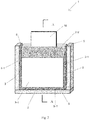
Fig. 1 is a structural diagram of an existing module structure of LCD, which is characterized in that a terminal part attached to a LCD controller is coated with a terminal part protective adhesive. At the same time, a module housing retaining wall is provided around the LCD panel, and the LCD panel is closely attached onto the module housing retaining wall to prevent foreign matters from entering the gap of the panel. - However, these solutions can only meet the reliability requirements of general industrial displays. When designing display panels, the selection of panel sealant is determined according to the preset reliability requirements. Once the design is finalized, users can no longer request panel manufacturers to change the design. Therefore, if it attempts to further improve the reliability of the display and meet the requirements of high reliability and longterm operation in harsh industrial environments, improved protective measures have to be adopted in module design.
- A display module is generally composed of a LCD panel, a liquid crystal controller, a flexible printed circuit board (FPC) and a housing assembly. According to the general concept of the present disclosure, in order to prevent ambient water vapor from penetrating into a liquid crystal box of the display panel, a grooved gap is designed between a panel edge and a retaining wall of housing (or backlight source), and a protective adhesive with excellent waterproof and airtightness performance such as UV adhesive (RTV adhesive, epoxy resin adhesive) is filled in the grooved gap. Moreover, the commonly used terminal part protective adhesive of the display is subjected to a stricter treatment for strengthening the waterproof and sealing performance, for example, increasing a coating thickness of the terminal part protective adhesive so that the terminal part protective adhesive flows over an upper surface of a front glass sheet of the panel and completely covers an edge of the front glass sheet, or coating another adhesive with waterproof function on the terminal part protective adhesive so as to completely cover the edge of the front glass sheet of the panel.
- Specifically, according to one aspect of the present disclosure, a module structure of a liquid crystal display is provided, which includes a panel glass assembly, a backlight assembly and a display housing retaining wall.
- An accommodating space formed by the display housing retaining wall accommodates the panel glass assembly and the backlight assembly.
- The panel glass assembly includes a front glass sheet, a rear glass sheet and a sealant for sealing a liquid crystal accommodating space between the front glass sheet and the rear glass sheet.
- A filling gap is provided between outer peripheral surfaces of the front glass sheet and the rear glass sheet of the panel glass assembly and an inner peripheral surface of the display housing retaining wall facing the outer peripheral surfaces.
- A panel edge protective adhesive is filled in the filling gap.
- According to the above aspect of the present disclosure, a liquid crystal display controller is provided on the terminal part of the rear glass sheet.
- A terminal part protective adhesive is coated on the terminal part, so that the terminal part protective adhesive completely covers the liquid crystal display controller and a height of the terminal part protective adhesive is equal to or greater than that of an upper surface of the front glass sheet.
- According to the above aspects of the disclosure, the terminal part protective adhesive is further coated on the terminal part, so that the terminal part protective adhesive flows over the upper surface of the front glass sheet and so that the terminal part protective adhesive completely covers the edge of the front glass sheet.
- According to the above aspects of the present disclosure, a waterproof adhesive is coated on the terminal part protective adhesive so that the waterproof adhesive covers the edge of the front glass sheet.
- According to the above aspects of the present disclosure, an elastic buffering sheet is provided between the backlight assembly and the rear glass sheet and is attached along a periphery of the rear glass sheet. The elastic buffering sheet is configured to prevent a panel edge protection adhesive from penetrating into a display area during a subsequent injection process of the panel edge protection adhesive.
- According to the above aspects of the present disclosure, a size of the filling gap is equal to or greater than 0.5 mm.
- According to the above aspects of the present disclosure, the panel edge protection adhesive is an ultraviolet curable adhesive. The panel edge protective adhesive is configured to strengthen a sealing performance of the sealant, which not only prevents a leakage of liquid crystal, but also prevents an infiltration of ambient water vapor into the sealant, thereby prolonging a service life of the liquid crystal display.
- According to the above aspects of the present disclosure, the terminal part protective adhesive is a room temperature vulcanized silicone rubber or an ultraviolet curable adhesive.
- According to another aspect of the present disclosure, a manufacturing process of a module structure of a liquid crystal display is proposed, the module structure includes a panel glass assembly, a backlight assembly and a display housing retaining wall.
- An accommodating space formed by the display housing retaining wall accommodates the panel glass assembly and the backlight assembly.
- The panel glass assembly includes a front glass sheet, a rear glass sheet and a sealant for sealing a liquid crystal accommodating space between the front glass sheet and the rear glass sheet.
- The manufacturing process includes a module designing stage.
- In the module designing stage, a filling gap is designed in advance between outer peripheral surfaces of the front sheet glass and the rear sheet glass of the panel glass assembly and an inner peripheral surface of the display housing retaining wall facing the outer peripheral surfaces.
- According to the above another aspect of the present disclosure, the manufacturing process further includes an attaching stage.
- In the attaching stage, attaching a flexible circuit board onto the rear glass sheet firstly.
- Then coating a terminal part protective adhesive on a terminal part of the rear glass sheet, so that a height of the terminal part protective adhesive is equal to or greater than that of an upper surface of the front glass sheet.
- According to the above another aspect of the present disclosure, the manufacturing process further comprises a module assembling stage.
- An elastic buffering sheet is provided between the backlight assembly and the rear glass sheet and is attached along a periphery of the rear glass sheet. The elastic buffering sheet is configured to prevent a panel edge protection adhesive from penetrating into a display area during a subsequent injection process of the panel edge protection adhesive.
- The panel glass assembly is attached in the display housing retaining wall.
- A panel edge protective adhesive is filled in the filling gap.
- The filled panel edge protective adhesive is cured with ultraviolet irradiation.
- The panel edge protective adhesive is configured to strengthen a sealing performance of the sealant, which not only prevents a leakage of liquid crystal, but also prevents an infiltration of ambient water vapor into the sealant, thereby prolonging a service life of the liquid crystal display.
- According to another aspect of the present disclosure, the terminal part protective adhesive is further coated on the terminal part, so that the terminal part protective adhesive flows over the upper surface of the front glass sheet and so that the terminal part protective adhesive completely covers the edge of the front glass sheet.
- According to another aspect of the present disclosure, a waterproof adhesive is coated on the terminal part protective adhesive so that the waterproof adhesive covers the edge of the front glass sheet.
- According to the above another aspect of the present disclosure, the filling gap is designed to have a size equal to or greater than 0.5 mm.
- According to the above another aspect of the present disclosure, an ultraviolet curable adhesive is selected as the panel edge protective adhesive.
- According to the above another aspect of the disclosure, a room temperature vulcanized silicone rubber or an ultraviolet curable adhesive is selected as the terminal part protective adhesive.
- According to the present disclosure, a design suitable for a high-reliability industrial display module is provided, so that the display can be used in harsh environments, such as power distribution products used in high-temperature and high-humidity environments.
- So far, in order that the detailed description of this disclosure can be better understood and the contribution of the present disclosure to the prior art can be better recognized, the present disclosure has summarized the contents of the present disclosure quite broadly. Of course, embodiments of the present disclosure will be described below and will form the subject matters of the appended claims.
- Likewise, those skilled in the art will recognize that the concepts on which the present disclosure is based can be easily used as a basis for designing other structures, methods and systems for carrying out several purposes of the present disclosure. Therefore, it is important that the appended claims should be considered to include such equivalent structures as long as they do not go beyond the spirit and scope of the present disclosure.
- From the following drawings, those skilled in the art will have a better understanding of the present disclosure, and the advantages of the present disclosure can be more clearly reflected. The drawings described herein are only for illustrative purposes of selected embodiments but not all possible implementations, and are not intended to limit the scope of the present disclosure.
-
Fig. 1 shows a schematic diagram of a module structure of a liquid crystal display in the prior art; -
Fig. 2 shows a schematic diagram of a module structure of a liquid crystal display according to the present disclosure; -
Fig. 3 shows a sectional view of a module structure of a liquid crystal display according to the present disclosure along A-A inFig. 2 ; and -
Fig. 4 shows a manufacturing process of a module structure of a liquid crystal display according to the present disclosure. -
Fig. 1 is a schematic diagram of a module structure of a liquid crystal display in the prior art, which is characterized in that, a terminal part of a controller bonded to the liquid crystal display is coated with a terminal partprotective adhesive 7. At the same time, a displayhousing retaining wall 3 is provided around a panel glass assembly 2 (including a front glass sheet and a rear glass sheet) of the liquid crystal display, and thepanel glass assembly 2 is closely attached onto the displayhousing retaining wall 3 to prevent foreign matters from entering a panel gap. - With reference to
Figs. 2 to 4 , specific embodiments according to the present disclosure will be described in detail below. - According to an embodiment of the present disclosure, a
module structure 1 of a liquid crystal display is provided. Themodule structure 1 includes apanel glass assembly 2, abacklight assembly 4 and a displayhousing retaining wall 3. - An accommodating space formed by the display
housing retaining wall 3 accommodates thepanel glass assembly 2 and thebacklight assembly 4. - As shown in
Fig. 2 , thepanel glass assembly 2 includes a front glass sheet 2-1, a rear glass sheet 2-2, and a sealant 2-3 for sealing a liquid crystal accommodating space 2-4 between the front glass sheet 2-1 and the rear glass sheet 2-2. - A filling
gap 5 is provided between outer peripheral surfaces of the front glass sheet 2-1 and the rear glass sheet 2-2 of thepanel glass assembly 2 and an inner peripheral surface of the displayhousing retaining wall 3 facing the outer peripheral surfaces. - The filling
gap 5 is filled with a panel edge protective adhesive 5-1. - According to the above embodiment of the present disclosure, a liquid crystal display controller 6 is provided on a terminal part 2-2-1 of the rear glass sheet 2-2.
- A terminal part
protective adhesive 7 is coated on the terminal part 2-2-1, so that the terminal partprotective adhesive 7 completely covers the liquid crystal display controller 6 and so that a height of the terminal partprotective adhesive 7 is equal to or higher than that of an upper surface 2-1-1 of the front glass sheet 2-1. - According to the above embodiments of the present disclosure, the terminal part
protective adhesive 7 is further coated on the terminal part 2-2-1, so that the terminal partprotective adhesive 7 flows over the upper surface 2-1-1 of the front glass sheet 2-1, so that the terminal partprotective adhesive 7 completely covers an edge 2-1-2 of the front glass sheet 2-1. - According to the above embodiments of the present disclosure, as shown in
Fig. 3 , awaterproof adhesive 8 is coated on the terminal partprotective adhesive 7 so that thewaterproof adhesive 8 covers the edge 2-1-2 of the front glass sheet 2-1. - According to the above embodiments of the present disclosure, an
elastic buffering sheet 9 is provided between thebacklight assembly 4 and the rear glass sheet 2-2 and attached along a periphery of the rear glass sheet 2-2. Theelastic buffering sheet 9 serves to prevent a panel edge protective adhesive 5-1 from penetrating into a display area during a subsequent injection process of the panel edge protective adhesive 5-1. - According to the above embodiments of the present disclosure, a size of the filling
gap 5 is equal to or greater than 0.5 mm. - According to the above embodiments of the present disclosure, the panel edge protection adhesive 5-1 is an ultraviolet curable adhesive. The panel edge protective adhesive 5-1 plays a role in strengthening a sealing performance of the sealant 2-3, which not only prevents from a leakage of liquid crystal but also prevents ambient water vapor from penetrating into the sealant 2-3, thereby prolonging a service life of the liquid crystal display.
- According to the above embodiments of the present disclosure, the terminal part
protective adhesive 7 is a room temperature vulcanized silicone rubber or an ultraviolet curable adhesive. - According to another embodiment of the present disclosure, as shown in
Fig. 4 , a manufacturing process of a module structure of a liquid crystal display is provided. It should be noted that the manufacturing process inFig. 4 is not unique, and an engineering designer can adjust, trim, merge and supplement the manufacturing process according to specific characteristics of a LCD panel and specific conditions of production lines. - As shown in
Figs. 2 and3 , themodule structure 1 includes apanel glass assembly 2, abacklight assembly 4 and a displayhousing retaining wall 3. - An accommodating space formed by the display
housing retaining wall 3 accommodates thepanel glass assembly 2 and thebacklight assembly 4. - The
panel glass assembly 2 includes a front glass sheet 2-1, a rear glass sheet 2-2, and a sealant 2-3 for sealing a liquid crystal accommodating space between the front glass sheet 2-1 and the rear glass sheet 2-2. - The manufacturing process includes a module designing stage S1.
- In the module designing stage S1, designing a
filling gap 5, in advance, between outer peripheral surfaces of the front glass sheet 2-1 and the rear glass sheet 2-2 of thepanel glass assembly 2 and an inner peripheral surface of the displayhousing retaining wall 3 facing the outer peripheral surfaces. - According to another embodiment of the present disclosure, the manufacturing process further includes an attaching stage S2.
- In the attaching stage S2, a
flexible circuit board 10 is attached onto the rear glass sheet 2-2 firstly (S2-1). - Then, a terminal part
protective adhesive 7 is coated on the terminal part 2-2-1 of the rear glass sheet 2-2, so that a height of the terminal partprotective adhesive 7 is equal to or greater than that of an upper surface 2-1-1 of the front glass sheet 2-1 (S2-2). - According to another embodiment of the present disclosure, the manufacturing process further includes a module assembling stage S3.
- In the module assembling stage S3, an
elastic buffering sheet 9 is provided between thebacklight assembly 4 and the rear glass sheet 2-2 and theelastic buffering sheet 9 is attached along a periphery of the rear glass sheet 2-2. Theelastic buffering sheet 9 serves to prevent a panel edge protective adhesive 5-1 from penetrating into a display area in a subsequent injection process of the panel edge protective adhesive 5-1 (S3-1). - The
panel glass assembly 2 is attached in the display housing retaining wall 3 (S3-2). - A panel edge protective adhesive 5-1 is filled in the filling gap 5 (S3-3).
- The filled panel edge protective adhesive 5-1 is cured with ultraviolet irradiation (S3-4).
- The panel edge protective adhesive 5-1 plays a role in strengthening a sealing performance of the sealant 2-3, which not only prevents from a leakage of liquid crystal but also prevents ambient water vapor from penetrating into the sealant 2-3, thereby prolonging a service life of the liquid crystal display.
- According to another embodiment of the present disclosure, a terminal part
protective adhesive 7 is further coated on the terminal part 2-2-1, so that the terminal partprotective adhesive 7 flows over an upper surface 2-1-1 of the front glass sheet 2-1 and so that the terminal partprotective adhesive 7 completely covers an edge 2-1-2 of the front glass sheet 2-1 (S3-5). - According to another embodiment of the present disclosure, a
waterproof adhesive 8 is coated on the terminal partprotective adhesive 7 so that thewaterproof adhesive 8 covers the edge 2-1-2 of the front glass sheet 2-1 (S3-6). - According to the above another embodiment of the present disclosure, the filling
gap 5 is designed to have a size equal to or greater than 0.5 mm. - According to the above another embodiment of the present disclosure, an ultraviolet curable adhesive is selected as the panel edge protective adhesive 5-1.
- According to the above another embodiment of the present disclosure, a room temperature vulcanized silicone rubber or an ultraviolet curable adhesive is selected as the terminal part
protective adhesive 7. - Although the present disclosure has been described in the specification and drawings with reference to specific embodiments, it should be understood that various changes can be made by those skilled in the art without departing from the scope of the present disclosure as defined in the claims, and various equivalents can be substituted for various elements therein. Furthermore, the combination and collocation of technical features, elements and/or functions among specific embodiments in the present disclosure are definite and clear, from which those skilled in the art can appreciate that the technical features, elements and/or functions of an embodiment can be combined into another specific embodiment as appropriate, unless otherwise described above. In addition, according to the teaching of the present disclosure, many changes can be made to adapt to special situations or materials without departing from the scope of the essence of the present disclosure. Therefore, the present disclosure is not limited to the specific embodiments illustrated in the drawings or the specific embodiments described in the specification as the best mode presently contemplated for carrying out the present disclosure, but the present disclosure is intended to include all embodiments falling within the scope of the above description and the appended claims.
Claims (15)
- A module structure of a liquid crystal display, the module structure comprising a panel glass assembly, a backlight assembly and a display housing retaining wall;
an accommodating space formed by the display housing retaining wall accommodating the panel glass assembly and the backlight assembly;
the panel glass assembly comprising a front glass sheet, a rear glass sheet and a sealant for sealing a liquid crystal accommodating space between the front glass sheet and the rear glass sheet;
characterized by that,
a filling gap is provided between outer peripheral surfaces of the front glass sheet and the rear glass sheet of the panel glass assembly and an inner peripheral surface of the display housing retaining wall facing the outer peripheral surfaces; and
a panel edge protective adhesive is filled in the filling gap. - The module structure according to claim 1, characterized by that,
a liquid crystal display controller is provided on a terminal part of the rear glass sheet; and
a terminal part protective adhesive is coated on the terminal part, so that the terminal part protective adhesive completely covers the liquid crystal display controller and a height of the terminal part protective adhesive is equal to or greater than that of an upper surface of the front glass sheet. - The module structure according to claim 2, characterized by that,
the terminal part protective adhesive is further coated on the terminal part, so that the terminal part protective adhesive flows over the upper surface of the front glass sheet and so that the terminal part protective adhesive completely covers an edge of the front glass sheet. - The module structure according to claim 2 or 3, characterized by that,
a waterproof adhesive is coated on the terminal part protective adhesive so that the waterproof adhesive covers an edge of the front glass sheet. - The module structure according to claim 1, characterized by that,
an elastic buffering sheet is provided between the backlight assembly and the rear glass sheet, and is attached along an periphery of the rear glass sheet. - The module structure according to claim 1, characterized by that,
a size of the filling gap is equal to or greater than 0.5 mm. - The module structure according to claim 1, characterized by that,
the panel edge protective adhesive is an ultraviolet curable adhesive. - The module structure according to claim 2 or 3, characterized by that,
the terminal part protective adhesive is a room temperature vulcanized silicone rubber or an ultraviolet curable adhesive. - A manufacturing process of a module structure of a liquid crystal display, the module structure comprising a panel glass assembly, a backlight assembly and a display housing retaining wall;
an accommodating space formed by the display housing retaining wall accommodating the panel glass assembly and the backlight assembly;
the panel glass assembly comprising a front glass sheet, a rear glass sheet and a sealant for sealing a liquid crystal accommodating space between the front glass sheet and the rear glass sheet;
characterized by that,
the manufacturing process comprises a module designing stage;
in the module designing stage, a filling gap is designed in advance between outer peripheral surfaces of the front glass sheet and the rear glass sheet of the panel glass assembly and an inner peripheral surface of the display housing retaining wall facing the outer peripheral surfaces. - The manufacturing process according to claim 9, characterized by that,
the manufacturing process further comprises a attaching stage;
in the attaching stage, a flexible circuit board is attached onto the rear glass sheet firstly;
a terminal part protective adhesive is then coated on a terminal part of the rear glass sheet, so that a height of the terminal part protective adhesive is equal to or greater than that of an upper surface of the front glass sheet. - The manufacturing process according to claim 10, characterized by that,
the manufacturing process further comprises a module assembling stage;
an elastic buffering sheet is provided between the backlight assembly and the rear glass sheet and is attached along a periphery of the rear glass sheet;
the panel glass assembly is attached in the display housing retaining wall;
a panel edge protective adhesive is filled in the filling gap; and
the filled, panel edge protective adhesive is cured with ultraviolet radiation. - The manufacturing process according to claim 11, characterized by that,
the terminal part protective adhesive is further coated on the terminal part, so that the terminal part protective adhesive flows over the upper surface of the front glass sheet and so that the terminal part protective adhesive completely covers an edge of the front glass sheet. - The manufacturing process according to claim 12, characterized by that,
a waterproof adhesive is coated on the terminal part protective adhesive so that the waterproof adhesive covers the edge of the front glass sheet. - The manufacturing process according to claim 9, characterized by that,
the filling gap is designed to have a size equal to or greater than 0.5 mm. - The manufacturing process according to claim 11, characterized by that,
an ultraviolet curable adhesive is selected as the panel edge protective adhesive, and
a room temperature vulcanized silicone rubber or an ultraviolet curable adhesive is selected as the terminal part protective adhesive.
Applications Claiming Priority (1)
| Application Number | Priority Date | Filing Date | Title |
|---|---|---|---|
| CN202010661089.1A CN113917739A (en) | 2020-07-10 | 2020-07-10 | Module structure of liquid crystal display and process for manufacturing module structure |
Publications (2)
| Publication Number | Publication Date |
|---|---|
| EP3936932A1 true EP3936932A1 (en) | 2022-01-12 |
| EP3936932B1 EP3936932B1 (en) | 2024-04-24 |
Family
ID=77042868
Family Applications (1)
| Application Number | Title | Priority Date | Filing Date |
|---|---|---|---|
| EP21305947.0A Active EP3936932B1 (en) | 2020-07-10 | 2021-07-08 | Module structure of liquid crystal display and manufacturing process of module structure |
Country Status (4)
| Country | Link |
|---|---|
| US (1) | US11573442B2 (en) |
| EP (1) | EP3936932B1 (en) |
| CN (1) | CN113917739A (en) |
| AU (1) | AU2021204823B2 (en) |
Citations (4)
| Publication number | Priority date | Publication date | Assignee | Title |
|---|---|---|---|---|
| US20110187956A1 (en) * | 2010-02-02 | 2011-08-04 | Samsung Mobile Display Co., Ltd. | Liquid crystal display device |
| KR20130033585A (en) * | 2011-09-27 | 2013-04-04 | 엘지디스플레이 주식회사 | Image display device |
| US20170184912A1 (en) * | 2015-12-28 | 2017-06-29 | Japan Display Inc. | Display device and method of manufacturing the same |
| US20170336694A1 (en) * | 2012-02-07 | 2017-11-23 | E Ink Holdings Inc. | Display device with water-proof glue |
Family Cites Families (6)
| Publication number | Priority date | Publication date | Assignee | Title |
|---|---|---|---|---|
| CN100535717C (en) * | 2005-02-17 | 2009-09-02 | 奇景光电股份有限公司 | Liquid crystal display module and packaging structure thereof |
| TWI457875B (en) * | 2009-02-19 | 2014-10-21 | Prime View Int Co Ltd | Display device and method of manufacturing same |
| KR101347566B1 (en) * | 2012-05-01 | 2014-01-06 | 엘지디스플레이 주식회사 | Display apparatus and method for manufacturing the same |
| CN103915065B (en) * | 2012-12-31 | 2016-06-08 | 施耐德电器工业公司 | Liquid crystal display module |
| CN108089365A (en) * | 2016-11-22 | 2018-05-29 | 群创光电股份有限公司 | Display device |
| CN212623490U (en) * | 2020-07-10 | 2021-02-26 | 施耐德电器工业公司 | Module structure of liquid crystal display |
-
2020
- 2020-07-10 CN CN202010661089.1A patent/CN113917739A/en active Pending
-
2021
- 2021-07-08 EP EP21305947.0A patent/EP3936932B1/en active Active
- 2021-07-09 US US17/371,365 patent/US11573442B2/en active Active
- 2021-07-09 AU AU2021204823A patent/AU2021204823B2/en active Active
Patent Citations (4)
| Publication number | Priority date | Publication date | Assignee | Title |
|---|---|---|---|---|
| US20110187956A1 (en) * | 2010-02-02 | 2011-08-04 | Samsung Mobile Display Co., Ltd. | Liquid crystal display device |
| KR20130033585A (en) * | 2011-09-27 | 2013-04-04 | 엘지디스플레이 주식회사 | Image display device |
| US20170336694A1 (en) * | 2012-02-07 | 2017-11-23 | E Ink Holdings Inc. | Display device with water-proof glue |
| US20170184912A1 (en) * | 2015-12-28 | 2017-06-29 | Japan Display Inc. | Display device and method of manufacturing the same |
Also Published As
| Publication number | Publication date |
|---|---|
| AU2021204823B2 (en) | 2022-10-20 |
| EP3936932B1 (en) | 2024-04-24 |
| CN113917739A (en) | 2022-01-11 |
| US11573442B2 (en) | 2023-02-07 |
| AU2021204823A1 (en) | 2022-01-27 |
| US20220011622A1 (en) | 2022-01-13 |
Similar Documents
| Publication | Publication Date | Title |
|---|---|---|
| US6556189B1 (en) | Touch panel device | |
| US8730424B2 (en) | Display apparatus | |
| CN212623490U (en) | Module structure of liquid crystal display | |
| JP2009122655A (en) | Display device | |
| US20070252922A1 (en) | Liquid crystal display device | |
| JP4727383B2 (en) | Liquid crystal display | |
| CN115421327A (en) | Cover plate, display module and manufacturing method thereof, and display device | |
| AU2021204823B2 (en) | Module structure of liquid crystal display and manufacturing process of module structure | |
| WO2020113644A1 (en) | Display panel and display device | |
| CN216119324U (en) | Display device | |
| CN210200207U (en) | Display devices and display equipment | |
| JP2008210199A (en) | Touch panel, manufacturing method for it, and electronic apparatus | |
| JP5389712B2 (en) | Liquid crystal display device and electronic apparatus including the same | |
| CN220627839U (en) | Waterproof LED display module assembly and display screen | |
| CN213400396U (en) | A dust-proof industrial control display module | |
| KR102292809B1 (en) | Display panel and manufacturing method thereof, display device, and terminal | |
| CN216901259U (en) | Display panel and display device | |
| CN219642042U (en) | Liquid crystal display screen capable of enhancing high-temperature high-humidity corrosion resistance | |
| US7411643B2 (en) | Liquid crystal display device and inspection method thereof | |
| CN110346973B (en) | Liquid crystal display backlight module | |
| CN220629806U (en) | Waterproof structure of electric quantity display device, battery equipment and unmanned ship | |
| CN223966791U (en) | Liquid crystal module backlight structure capable of preventing invasion of foreign matters | |
| CN111025805A (en) | Array substrate, liquid crystal display panel and device | |
| CN219938593U (en) | Light leakage prevention lamp display switch circuit structure | |
| CN209118245U (en) | touch display device |
Legal Events
| Date | Code | Title | Description |
|---|---|---|---|
| PUAI | Public reference made under article 153(3) epc to a published international application that has entered the european phase |
Free format text: ORIGINAL CODE: 0009012 |
|
| STAA | Information on the status of an ep patent application or granted ep patent |
Free format text: STATUS: THE APPLICATION HAS BEEN PUBLISHED |
|
| AK | Designated contracting states |
Kind code of ref document: A1 Designated state(s): AL AT BE BG CH CY CZ DE DK EE ES FI FR GB GR HR HU IE IS IT LI LT LU LV MC MK MT NL NO PL PT RO RS SE SI SK SM TR |
|
| B565 | Issuance of search results under rule 164(2) epc |
Effective date: 20211123 |
|
| STAA | Information on the status of an ep patent application or granted ep patent |
Free format text: STATUS: REQUEST FOR EXAMINATION WAS MADE |
|
| 17P | Request for examination filed |
Effective date: 20220711 |
|
| RBV | Designated contracting states (corrected) |
Designated state(s): AL AT BE BG CH CY CZ DE DK EE ES FI FR GB GR HR HU IE IS IT LI LT LU LV MC MK MT NL NO PL PT RO RS SE SI SK SM TR |
|
| STAA | Information on the status of an ep patent application or granted ep patent |
Free format text: STATUS: EXAMINATION IS IN PROGRESS |
|
| 17Q | First examination report despatched |
Effective date: 20230322 |
|
| GRAP | Despatch of communication of intention to grant a patent |
Free format text: ORIGINAL CODE: EPIDOSNIGR1 |
|
| STAA | Information on the status of an ep patent application or granted ep patent |
Free format text: STATUS: GRANT OF PATENT IS INTENDED |
|
| INTG | Intention to grant announced |
Effective date: 20240209 |
|
| GRAS | Grant fee paid |
Free format text: ORIGINAL CODE: EPIDOSNIGR3 |
|
| GRAA | (expected) grant |
Free format text: ORIGINAL CODE: 0009210 |
|
| STAA | Information on the status of an ep patent application or granted ep patent |
Free format text: STATUS: THE PATENT HAS BEEN GRANTED |
|
| AK | Designated contracting states |
Kind code of ref document: B1 Designated state(s): AL AT BE BG CH CY CZ DE DK EE ES FI FR GB GR HR HU IE IS IT LI LT LU LV MC MK MT NL NO PL PT RO RS SE SI SK SM TR |
|
| REG | Reference to a national code |
Ref country code: GB Ref legal event code: FG4D |
|
| REG | Reference to a national code |
Ref country code: CH Ref legal event code: EP |
|
| REG | Reference to a national code |
Ref country code: DE Ref legal event code: R096 Ref document number: 602021012231 Country of ref document: DE |
|
| REG | Reference to a national code |
Ref country code: IE Ref legal event code: FG4D |
|
| REG | Reference to a national code |
Ref country code: LT Ref legal event code: MG9D |
|
| REG | Reference to a national code |
Ref country code: NL Ref legal event code: MP Effective date: 20240424 |
|
| REG | Reference to a national code |
Ref country code: AT Ref legal event code: MK05 Ref document number: 1680235 Country of ref document: AT Kind code of ref document: T Effective date: 20240424 |
|
| PG25 | Lapsed in a contracting state [announced via postgrant information from national office to epo] |
Ref country code: NL Free format text: LAPSE BECAUSE OF FAILURE TO SUBMIT A TRANSLATION OF THE DESCRIPTION OR TO PAY THE FEE WITHIN THE PRESCRIBED TIME-LIMIT Effective date: 20240424 |
|
| PG25 | Lapsed in a contracting state [announced via postgrant information from national office to epo] |
Ref country code: NL Free format text: LAPSE BECAUSE OF FAILURE TO SUBMIT A TRANSLATION OF THE DESCRIPTION OR TO PAY THE FEE WITHIN THE PRESCRIBED TIME-LIMIT Effective date: 20240424 |
|
| PG25 | Lapsed in a contracting state [announced via postgrant information from national office to epo] |
Ref country code: IS Free format text: LAPSE BECAUSE OF FAILURE TO SUBMIT A TRANSLATION OF THE DESCRIPTION OR TO PAY THE FEE WITHIN THE PRESCRIBED TIME-LIMIT Effective date: 20240824 |
|
| PG25 | Lapsed in a contracting state [announced via postgrant information from national office to epo] |
Ref country code: BG Free format text: LAPSE BECAUSE OF FAILURE TO SUBMIT A TRANSLATION OF THE DESCRIPTION OR TO PAY THE FEE WITHIN THE PRESCRIBED TIME-LIMIT Effective date: 20240424 |
|
| PG25 | Lapsed in a contracting state [announced via postgrant information from national office to epo] |
Ref country code: HR Free format text: LAPSE BECAUSE OF FAILURE TO SUBMIT A TRANSLATION OF THE DESCRIPTION OR TO PAY THE FEE WITHIN THE PRESCRIBED TIME-LIMIT Effective date: 20240424 Ref country code: FI Free format text: LAPSE BECAUSE OF FAILURE TO SUBMIT A TRANSLATION OF THE DESCRIPTION OR TO PAY THE FEE WITHIN THE PRESCRIBED TIME-LIMIT Effective date: 20240424 |
|
| PG25 | Lapsed in a contracting state [announced via postgrant information from national office to epo] |
Ref country code: GR Free format text: LAPSE BECAUSE OF FAILURE TO SUBMIT A TRANSLATION OF THE DESCRIPTION OR TO PAY THE FEE WITHIN THE PRESCRIBED TIME-LIMIT Effective date: 20240725 |
|
| PG25 | Lapsed in a contracting state [announced via postgrant information from national office to epo] |
Ref country code: PT Free format text: LAPSE BECAUSE OF FAILURE TO SUBMIT A TRANSLATION OF THE DESCRIPTION OR TO PAY THE FEE WITHIN THE PRESCRIBED TIME-LIMIT Effective date: 20240826 |
|
| PG25 | Lapsed in a contracting state [announced via postgrant information from national office to epo] |
Ref country code: ES Free format text: LAPSE BECAUSE OF FAILURE TO SUBMIT A TRANSLATION OF THE DESCRIPTION OR TO PAY THE FEE WITHIN THE PRESCRIBED TIME-LIMIT Effective date: 20240424 |
|
| PG25 | Lapsed in a contracting state [announced via postgrant information from national office to epo] |
Ref country code: AT Free format text: LAPSE BECAUSE OF FAILURE TO SUBMIT A TRANSLATION OF THE DESCRIPTION OR TO PAY THE FEE WITHIN THE PRESCRIBED TIME-LIMIT Effective date: 20240424 |
|
| PG25 | Lapsed in a contracting state [announced via postgrant information from national office to epo] |
Ref country code: PL Free format text: LAPSE BECAUSE OF FAILURE TO SUBMIT A TRANSLATION OF THE DESCRIPTION OR TO PAY THE FEE WITHIN THE PRESCRIBED TIME-LIMIT Effective date: 20240424 |
|
| PG25 | Lapsed in a contracting state [announced via postgrant information from national office to epo] |
Ref country code: LV Free format text: LAPSE BECAUSE OF FAILURE TO SUBMIT A TRANSLATION OF THE DESCRIPTION OR TO PAY THE FEE WITHIN THE PRESCRIBED TIME-LIMIT Effective date: 20240424 |
|
| PG25 | Lapsed in a contracting state [announced via postgrant information from national office to epo] |
Ref country code: PT Free format text: LAPSE BECAUSE OF FAILURE TO SUBMIT A TRANSLATION OF THE DESCRIPTION OR TO PAY THE FEE WITHIN THE PRESCRIBED TIME-LIMIT Effective date: 20240826 Ref country code: PL Free format text: LAPSE BECAUSE OF FAILURE TO SUBMIT A TRANSLATION OF THE DESCRIPTION OR TO PAY THE FEE WITHIN THE PRESCRIBED TIME-LIMIT Effective date: 20240424 Ref country code: NO Free format text: LAPSE BECAUSE OF FAILURE TO SUBMIT A TRANSLATION OF THE DESCRIPTION OR TO PAY THE FEE WITHIN THE PRESCRIBED TIME-LIMIT Effective date: 20240724 Ref country code: LV Free format text: LAPSE BECAUSE OF FAILURE TO SUBMIT A TRANSLATION OF THE DESCRIPTION OR TO PAY THE FEE WITHIN THE PRESCRIBED TIME-LIMIT Effective date: 20240424 Ref country code: IS Free format text: LAPSE BECAUSE OF FAILURE TO SUBMIT A TRANSLATION OF THE DESCRIPTION OR TO PAY THE FEE WITHIN THE PRESCRIBED TIME-LIMIT Effective date: 20240824 Ref country code: HR Free format text: LAPSE BECAUSE OF FAILURE TO SUBMIT A TRANSLATION OF THE DESCRIPTION OR TO PAY THE FEE WITHIN THE PRESCRIBED TIME-LIMIT Effective date: 20240424 Ref country code: GR Free format text: LAPSE BECAUSE OF FAILURE TO SUBMIT A TRANSLATION OF THE DESCRIPTION OR TO PAY THE FEE WITHIN THE PRESCRIBED TIME-LIMIT Effective date: 20240725 Ref country code: FI Free format text: LAPSE BECAUSE OF FAILURE TO SUBMIT A TRANSLATION OF THE DESCRIPTION OR TO PAY THE FEE WITHIN THE PRESCRIBED TIME-LIMIT Effective date: 20240424 Ref country code: ES Free format text: LAPSE BECAUSE OF FAILURE TO SUBMIT A TRANSLATION OF THE DESCRIPTION OR TO PAY THE FEE WITHIN THE PRESCRIBED TIME-LIMIT Effective date: 20240424 Ref country code: BG Free format text: LAPSE BECAUSE OF FAILURE TO SUBMIT A TRANSLATION OF THE DESCRIPTION OR TO PAY THE FEE WITHIN THE PRESCRIBED TIME-LIMIT Effective date: 20240424 Ref country code: AT Free format text: LAPSE BECAUSE OF FAILURE TO SUBMIT A TRANSLATION OF THE DESCRIPTION OR TO PAY THE FEE WITHIN THE PRESCRIBED TIME-LIMIT Effective date: 20240424 Ref country code: RS Free format text: LAPSE BECAUSE OF FAILURE TO SUBMIT A TRANSLATION OF THE DESCRIPTION OR TO PAY THE FEE WITHIN THE PRESCRIBED TIME-LIMIT Effective date: 20240724 |
|
| PG25 | Lapsed in a contracting state [announced via postgrant information from national office to epo] |
Ref country code: DK Free format text: LAPSE BECAUSE OF FAILURE TO SUBMIT A TRANSLATION OF THE DESCRIPTION OR TO PAY THE FEE WITHIN THE PRESCRIBED TIME-LIMIT Effective date: 20240424 |
|
| PG25 | Lapsed in a contracting state [announced via postgrant information from national office to epo] |
Ref country code: EE Free format text: LAPSE BECAUSE OF FAILURE TO SUBMIT A TRANSLATION OF THE DESCRIPTION OR TO PAY THE FEE WITHIN THE PRESCRIBED TIME-LIMIT Effective date: 20240424 |
|
| PG25 | Lapsed in a contracting state [announced via postgrant information from national office to epo] |
Ref country code: CZ Free format text: LAPSE BECAUSE OF FAILURE TO SUBMIT A TRANSLATION OF THE DESCRIPTION OR TO PAY THE FEE WITHIN THE PRESCRIBED TIME-LIMIT Effective date: 20240424 |
|
| PG25 | Lapsed in a contracting state [announced via postgrant information from national office to epo] |
Ref country code: SK Free format text: LAPSE BECAUSE OF FAILURE TO SUBMIT A TRANSLATION OF THE DESCRIPTION OR TO PAY THE FEE WITHIN THE PRESCRIBED TIME-LIMIT Effective date: 20240424 Ref country code: RO Free format text: LAPSE BECAUSE OF FAILURE TO SUBMIT A TRANSLATION OF THE DESCRIPTION OR TO PAY THE FEE WITHIN THE PRESCRIBED TIME-LIMIT Effective date: 20240424 |
|
| REG | Reference to a national code |
Ref country code: DE Ref legal event code: R097 Ref document number: 602021012231 Country of ref document: DE |
|
| PG25 | Lapsed in a contracting state [announced via postgrant information from national office to epo] |
Ref country code: SM Free format text: LAPSE BECAUSE OF FAILURE TO SUBMIT A TRANSLATION OF THE DESCRIPTION OR TO PAY THE FEE WITHIN THE PRESCRIBED TIME-LIMIT Effective date: 20240424 |
|
| PG25 | Lapsed in a contracting state [announced via postgrant information from national office to epo] |
Ref country code: SM Free format text: LAPSE BECAUSE OF FAILURE TO SUBMIT A TRANSLATION OF THE DESCRIPTION OR TO PAY THE FEE WITHIN THE PRESCRIBED TIME-LIMIT Effective date: 20240424 Ref country code: SK Free format text: LAPSE BECAUSE OF FAILURE TO SUBMIT A TRANSLATION OF THE DESCRIPTION OR TO PAY THE FEE WITHIN THE PRESCRIBED TIME-LIMIT Effective date: 20240424 Ref country code: RO Free format text: LAPSE BECAUSE OF FAILURE TO SUBMIT A TRANSLATION OF THE DESCRIPTION OR TO PAY THE FEE WITHIN THE PRESCRIBED TIME-LIMIT Effective date: 20240424 Ref country code: EE Free format text: LAPSE BECAUSE OF FAILURE TO SUBMIT A TRANSLATION OF THE DESCRIPTION OR TO PAY THE FEE WITHIN THE PRESCRIBED TIME-LIMIT Effective date: 20240424 Ref country code: DK Free format text: LAPSE BECAUSE OF FAILURE TO SUBMIT A TRANSLATION OF THE DESCRIPTION OR TO PAY THE FEE WITHIN THE PRESCRIBED TIME-LIMIT Effective date: 20240424 Ref country code: CZ Free format text: LAPSE BECAUSE OF FAILURE TO SUBMIT A TRANSLATION OF THE DESCRIPTION OR TO PAY THE FEE WITHIN THE PRESCRIBED TIME-LIMIT Effective date: 20240424 |
|
| PG25 | Lapsed in a contracting state [announced via postgrant information from national office to epo] |
Ref country code: MC Free format text: LAPSE BECAUSE OF FAILURE TO SUBMIT A TRANSLATION OF THE DESCRIPTION OR TO PAY THE FEE WITHIN THE PRESCRIBED TIME-LIMIT Effective date: 20240424 |
|
| PLBE | No opposition filed within time limit |
Free format text: ORIGINAL CODE: 0009261 |
|
| REG | Reference to a national code |
Ref country code: CH Ref legal event code: PL |
|
| STAA | Information on the status of an ep patent application or granted ep patent |
Free format text: STATUS: NO OPPOSITION FILED WITHIN TIME LIMIT |
|
| PG25 | Lapsed in a contracting state [announced via postgrant information from national office to epo] |
Ref country code: LU Free format text: LAPSE BECAUSE OF NON-PAYMENT OF DUE FEES Effective date: 20240708 |
|
| PG25 | Lapsed in a contracting state [announced via postgrant information from national office to epo] |
Ref country code: LU Free format text: LAPSE BECAUSE OF NON-PAYMENT OF DUE FEES Effective date: 20240708 |
|
| 26N | No opposition filed |
Effective date: 20250127 |
|
| PG25 | Lapsed in a contracting state [announced via postgrant information from national office to epo] |
Ref country code: SI Free format text: LAPSE BECAUSE OF FAILURE TO SUBMIT A TRANSLATION OF THE DESCRIPTION OR TO PAY THE FEE WITHIN THE PRESCRIBED TIME-LIMIT Effective date: 20240424 Ref country code: CH Free format text: LAPSE BECAUSE OF NON-PAYMENT OF DUE FEES Effective date: 20240731 Ref country code: BE Free format text: LAPSE BECAUSE OF NON-PAYMENT OF DUE FEES Effective date: 20240731 |
|
| REG | Reference to a national code |
Ref country code: BE Ref legal event code: MM Effective date: 20240731 |
|
| PG25 | Lapsed in a contracting state [announced via postgrant information from national office to epo] |
Ref country code: IE Free format text: LAPSE BECAUSE OF NON-PAYMENT OF DUE FEES Effective date: 20240708 |
|
| PG25 | Lapsed in a contracting state [announced via postgrant information from national office to epo] |
Ref country code: SE Free format text: LAPSE BECAUSE OF FAILURE TO SUBMIT A TRANSLATION OF THE DESCRIPTION OR TO PAY THE FEE WITHIN THE PRESCRIBED TIME-LIMIT Effective date: 20240424 |
|
| PGFP | Annual fee paid to national office [announced via postgrant information from national office to epo] |
Ref country code: DE Payment date: 20250728 Year of fee payment: 5 |
|
| PGFP | Annual fee paid to national office [announced via postgrant information from national office to epo] |
Ref country code: FR Payment date: 20250725 Year of fee payment: 5 |
|
| PG25 | Lapsed in a contracting state [announced via postgrant information from national office to epo] |
Ref country code: CY Free format text: LAPSE BECAUSE OF FAILURE TO SUBMIT A TRANSLATION OF THE DESCRIPTION OR TO PAY THE FEE WITHIN THE PRESCRIBED TIME-LIMIT; INVALID AB INITIO Effective date: 20210708 |
|
| PG25 | Lapsed in a contracting state [announced via postgrant information from national office to epo] |
Ref country code: IT Free format text: LAPSE BECAUSE OF FAILURE TO SUBMIT A TRANSLATION OF THE DESCRIPTION OR TO PAY THE FEE WITHIN THE PRESCRIBED TIME-LIMIT Effective date: 20240424 |
|
| PG25 | Lapsed in a contracting state [announced via postgrant information from national office to epo] |
Ref country code: HU Free format text: LAPSE BECAUSE OF FAILURE TO SUBMIT A TRANSLATION OF THE DESCRIPTION OR TO PAY THE FEE WITHIN THE PRESCRIBED TIME-LIMIT; INVALID AB INITIO Effective date: 20210708 |
|
| GBPC | Gb: european patent ceased through non-payment of renewal fee |
Effective date: 20250708 |
|
| PG25 | Lapsed in a contracting state [announced via postgrant information from national office to epo] |
Ref country code: GB Free format text: LAPSE BECAUSE OF NON-PAYMENT OF DUE FEES Effective date: 20250708 |