EP3936849A1 - Rolling bearing status monitoring system and status monitoring method - Google Patents
Rolling bearing status monitoring system and status monitoring method Download PDFInfo
- Publication number
- EP3936849A1 EP3936849A1 EP19919171.9A EP19919171A EP3936849A1 EP 3936849 A1 EP3936849 A1 EP 3936849A1 EP 19919171 A EP19919171 A EP 19919171A EP 3936849 A1 EP3936849 A1 EP 3936849A1
- Authority
- EP
- European Patent Office
- Prior art keywords
- pulse wave
- roller bearing
- condition monitoring
- monitoring system
- vibration
- Prior art date
- Legal status (The legal status is an assumption and is not a legal conclusion. Google has not performed a legal analysis and makes no representation as to the accuracy of the status listed.)
- Granted
Links
Images





Classifications
-
- G—PHYSICS
- G01—MEASURING; TESTING
- G01H—MEASUREMENT OF MECHANICAL VIBRATIONS OR ULTRASONIC, SONIC OR INFRASONIC WAVES
- G01H1/00—Measuring characteristics of vibrations in solids by using direct conduction to the detector
- G01H1/003—Measuring characteristics of vibrations in solids by using direct conduction to the detector of rotating machines
-
- G—PHYSICS
- G01—MEASURING; TESTING
- G01M—TESTING STATIC OR DYNAMIC BALANCE OF MACHINES OR STRUCTURES; TESTING OF STRUCTURES OR APPARATUS, NOT OTHERWISE PROVIDED FOR
- G01M13/00—Testing of machine parts
- G01M13/04—Bearings
- G01M13/045—Acoustic or vibration analysis
Definitions
- the present invention relates to a condition monitoring system and a condition monitoring method of a roller bearing.
- a vibration acceleration sensor For monitoring the condition of a roller bearing, a vibration acceleration sensor is often used as disclosed in PTL 1, PTL 2, and NPTL 1.
- the standard condition monitoring method of a bearing based on vibration acceleration measurement is now explained with reference to Fig. 9 .
- a pulse wave is generated each time a rolling element passes by that fault. Moreover, if there is any fault on the rolling element, a pulse wave is generated each time that such fault collides with the inner ring track surface or the outer ring track surface based on the rotation of the rolling element.
- a periodic shock pulse wave is generated at timing t1 and timing t2 when the rolling element passes by the fault on the outer ring track surface as shown in the right diagram.
- These periodic shock pulse waves have a waveform as shown in Fig. 9(b) , and excite the circular vibration of the outer ring of the bearing.
- This vibration frequency is a high frequency, and in certain cases it may be 10 kHz or higher.
- a vibration acceleration sensor is placed around the roller bearing, and the circular vibration is measured at a sampling rate capable of capturing such circular vibration.
- an envelope is detected as shown in Fig. 9(c) in relation to the obtained vibration waveform, and a pulse wave caused by the fault on the inside of the bearing is extracted.
- Fig. 9(d) the frequency that the rolling element passes by the fault and the amplitude value that is double the rotation frequency of the rolling element are evaluated based on FFT operation processing.
- An abnormality of the bearing is determined by monitoring the time change of the amplitude value as shown in Fig. 9(e) .
- An object of the present invention is to provide, at a low cost, a condition monitoring system for monitoring a roller bearing in order to resolve the foregoing problems.
- the present invention provides a condition monitoring system of a roller bearing which supports a rotating shaft, comprising: a vibration measurement unit which measures a vibration of the roller bearing; an envelope detection unit which detects an envelope of an amplitude of a vibration waveform based on the vibration of the roller bearing measured with the vibration measurement unit; a pulse wave search unit which searches for a pulse wave of a cycle that matches a predetermined cycle based on a theoretical frequency of a vibration waveform, which is generated when the roller bearing is damaged, from the envelope detected with the envelope detection unit; and a pulse wave extraction unit which extracts a pulse wave of a maximum amplitude value from a pulse wave of a cycle that matches the predetermined cycle obtained from the search conducted by the pulse wave search unit, wherein condition monitoring of the roller bearing is performed based on the maximum amplitude value of the pulse wave extracted with the pulse wave extraction unit.
- the present invention additionally provides a condition monitoring method of a roller bearing executed by a condition monitoring system of a roller bearing which supports a rotating shaft, comprising: a vibration measurement step of measuring a vibration of the roller bearing; an envelope detection step of detecting an envelope of an amplitude of a vibration waveform based on the vibration of the roller bearing measured with the vibration measurement unit; a pulse wave search step of searching for a pulse wave of a cycle that matches a predetermined cycle based on a theoretical frequency of a vibration waveform, which is generated when the roller bearing is damaged, from the envelope detected with the envelope detection unit; a pulse wave extraction step of extracting a pulse wave of a maximum amplitude value from a pulse wave of a cycle that matches the predetermined cycle obtained from the search conducted by the pulse wave search unit; and a condition monitoring step of performing condition monitoring of the roller bearing based on the maximum amplitude value of the pulse wave extracted in the pulse wave extraction step.
- the present invention it is possible to detect an abnormality of a bearing with the same precision as high-speed sampling by performing sampling at a low speed and a short data length, and reduce the cost of introducing a condition monitoring system.
- roller bearing includes a rolling ball bearing comprising a cylindrical inner ring disposed so as to cover an outer peripheral surface of a rotating shaft, a cylindrical outer ring disposed concentrically so as to cover an outer peripheral surface of a cylindrical inner ring and be separated at a predetermined spacing radially outward from the outer peripheral surface of the inner ring, and a bearing housing disposed so as to cover an outer peripheral surface of an outer ring, wherein a plurality of spherical balls, as rolling elements, are disposed in a circumferential direction between the outer peripheral surface of the inner ring and the inner peripheral surface of the outer ring, and a rolling roller bearing in which a plurality of columnar rollers, as rolling elements, are disposed in a circumferential direction between the outer peripheral surface of the inner ring and the inner peripheral surface of the outer ring.
- roller bearing also include a deep groove bearing in which a plurality of arc-like deep grooves are formed in a circumferential direction and at a predetermined spacing on an outer peripheral surface of a cylindrical inner ring, wherein arc-like deep grooves are formed on an inner peripheral surface of a cylindrical outer ring at positions facing the deep grooves formed on the outer peripheral surface of the inner ring.
- the following embodiments can be applied to wind generator systems, construction machines, railways, elevators and other technical fields.
- Fig. 1 is an overall schematic configuration diagram of the roller bearing condition monitoring system according to the first embodiment.
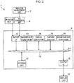
- Fig. 2 is a functional block diagram of the roller bearing condition monitoring system according to the first embodiment.
- the roller bearing condition monitoring system 1 includes at least a display unit 10, a vibration measurement unit 7 such as a sensor for measuring a vibration of a roller bearing 2, an AID conversion unit 8 which converts a measured analog vibration waveform into a digital vibration waveform, and a control unit 9 which performs operation processing to the measured signals and graphically shows the results and monitors the condition of the roller bearing.
- a vibration measurement unit 7 such as a sensor for measuring a vibration of a roller bearing 2
- an AID conversion unit 8 which converts a measured analog vibration waveform into a digital vibration waveform
- control unit 9 which performs operation processing to the measured signals and graphically shows the results and monitors the condition of the roller bearing.
- the roller bearing 2 includes, as shown in Fig. 1 , a cylindrical inner ring 4 disposed so as to cover an outer peripheral surface of a rotating shaft 3 and which engages with the rotating shaft 3, a cylindrical outer ring 5 disposed concentrically so as to cover an outer peripheral surface of the cylindrical inner ring 4 and be separated at a predetermined spacing radially outward from the outer peripheral surface of the inner ring 4, and a plurality of rolling elements 6 disposed in a circumferential direction between the outer peripheral surface of the inner ring 4 and the inner peripheral surface of the outer ring 5 so as to be mutually separated at a predetermined spacing.
- Fig. 1 a cylindrical inner ring 4 disposed so as to cover an outer peripheral surface of a rotating shaft 3 and which engages with the rotating shaft 3, a cylindrical outer ring 5 disposed concentrically so as to cover an outer peripheral surface of the cylindrical inner ring 4 and be separated at a predetermined spacing radially outward from the outer peripheral surface of the inner ring 4, and a plurality of rolling elements 6 disposed
- FIG. 1 shows a vertical cross section of the inner ring 4, the outer ring 5, and the rolling elements 6 of the roller bearing 2, and shows the part of the rotating shaft 3 that engages with the roller bearing 2. Moreover, in Fig. 1 , the bearing housing that covers the outer peripheral surface of the outer ring 5 has been omitted.
- roller bearing condition monitoring system 1 may also include multiple sets of the roller bearing 2 and the vibration measurement unit 7. In the foregoing case, the roller bearing condition monitoring system 1 is able to identify the respective roller bearings 2.
- the roller bearing condition monitoring system 1 of this embodiment includes a vibration measurement unit 7, an A/D conversion unit 8, a control unit 9, and a display unit 10 such as an LCD (Liquid Crystal Display), an LED (Light Emitting Diode) display or an organic EL (Electro Luminescence) display.
- a vibration measurement unit 7 an A/D conversion unit 8
- a control unit 9 a control unit 9
- a display unit 10 such as an LCD (Liquid Crystal Display), an LED (Light Emitting Diode) display or an organic EL (Electro Luminescence) display.
- the control unit 9 includes an input I/F 12, a measured value acquisition unit 13, an envelope detection unit 14, a pulse wave search unit 15, a maximum pulse wave extraction unit 16, a storage unit 17, and an output I/F 18. These components are mutually connected via an internal bus 19.
- the input I/F 12 accepts the input of measured values of the vibration waveform measured with the vibration measurement unit 7 and thereafter digitized with the A/D conversion unit 8, and of input values of operation data (for example, rotation frequency ⁇ of the roller bearing 2).
- the measured value acquisition unit 13 acquires, via the input I/F 12, the measured values including the vibration waveform measured with the vibration measurement unit 7 and thereafter digitized with the A/D conversion unit 8. This acquired value is transferred to the envelope detection unit 14 via the internal bus 19, and stored in a predetermined storage area of the storage unit 17. Moreover, the measured value acquisition unit 13 converts the measured rotation speed of the roller bearing 2 into rotation speed data by using, for example, an encoder (not shown) or the like, transfers the converted rotation speed data to the pulse wave search unit 15 via the internal bus 19, and stores such converted rotation speed data in a predetermined storage area of the storage unit 17.
- the envelope detection unit 14 performs absolute value rectification to the digital vibration waveform acquired with the measured value acquisition unit 13.
- the pulse wave search unit 15 searches for a pulse wave which is generated in a theoretically obtained generation cycle T of the pulse wave stored in the storage unit 17 from the digital vibration waveform that underwent the absolute value rectification performed by the envelope detection unit 14.
- the generation cycle T of the pulse wave will be explained later.
- the maximum pulse wave extraction unit 16 extracts a pulse wave in which the amplitude becomes maximum from the pulse wave searched with the pulse wave search unit 15.
- the maximum pulse wave extraction unit 16 obtains the amplitude value of each of the extracted pulse waves and transfers the results to the maximum pulse wave extraction unit 16 via the internal bus 19.
- the maximum pulse wave extraction unit 16 obtains a maximum value of the amplitude among the pulse waves transferred from the pulse wave search unit 15 via the internal bus 19, and stores the obtained maximum value in a predetermined storage area of the storage unit 17 via the internal bus 19.
- the maximum value of the amplitude obtained with the maximum pulse wave extraction unit 16 is displayed on a screen of the display unit 10 via the output I/F 18.
- the storage unit 17 stores the generation cycle T of the pulse wave of the vibration, which occurs when a fault occurs in the roller bearing 2, theoretically obtained from the specification of the roller bearing 2.
- the storage unit 17 stores the generation cycle T of the pulse wave for each roller bearing 2 having the same specification.
- the generation cycle T of the pulse wave of the vibration stored in the storage unit 17 there are a generation cycle T1 of the pulse wave when a fault occurs in the inner ring 4, a generation cycle T2 of the pulse wave when a fault occurs in the outer ring 5, and a generation cycle T3 of the pulse wave when a fault occurs in the rolling element 6.
- the generation cycle T1 of the pulse wave is, when a fault occurs in the inner ring 4, a reciprocal of a frequency f1 of the pulse wave which is generated when the rolling element 6 passes by that fault calculated based on Formula (1) below.
- the frequency f1 of the pulse wave is also referred to as an inner ring rolling element passing frequency.
- the generation cycle T2 of the pulse wave is, when a fault occurs in the outer ring 5, a reciprocal of a frequency f2 of the pulse wave which is generated when the rolling element 6 passes by that fault calculated based on Formula (2) below.
- the frequency f1 of the pulse wave is also referred to as an outer ring rolling element passing frequency.
- the generation cycle T3 of the pulse wave is a reciprocal of a frequency f3 of the pulse wave which is generated when a fault occurs in the rolling element 6 and the fault collides at two locations; specifically, with the inner ring 4 and with the outer ring 5, calculated based on Formula (3) below.
- the frequency f3 of the pulse wave is a frequency that is double the rotation frequency of the rolling element 6.
- the envelope detection unit 14, the pulse wave search unit 15, and the maximum pulse wave extraction unit 16 are realized, for example, by a storage device such as a ROM which stores various programs or a RAM which temporarily stores data in the course of performing operations or in the course of executing programs, or by a processor such as a CPU which executes various programs stored in a ROM.
- Fig. 3 is an overall processing flowchart of the roller bearing condition monitoring system according to the first embodiment.
- the overall processing of the roller bearing condition monitoring system according to the first embodiment is executed based on a predetermined execution trigger.
- the execution trigger of the overall processing of the roller bearing condition monitoring system considered may be the following.
- the monitoring target of the roller bearing condition is a railway
- the execution trigger may be that the train has passed a predetermined route, or that the train has reached a predetermined running speed (steady speed, etc.).
- the monitoring target of the roller bearing condition is a windmill
- the execution trigger may be that the windmill has reached a steady operation (steady output or steady rotation speed, etc.).
- the overall processing of the roller bearing condition monitoring system may be executed in predetermined time intervals after reaching such steady operation.
- the roller bearing condition monitoring condition can be made constant and the monitoring accuracy can be ensured by executing the overall processing of the roller bearing condition monitoring system based on a predetermined execution trigger.
- the vibration measurement result according to this embodiment is shown with a solid line
- the vibration measurement result of the comparative example is shown with a broken line.
- the vibration is sampled at a sampling rate that is lower than a predetermined rate
- the vibration is sampled at a sampling rate that is higher than a predetermined rate.
- step S1 the vibration measurement unit 7 in the roller bearing condition monitoring system 1 measures the vibration in the vicinity of the roller bearing 2 using a vibration acceleration sensor at a sampling rate that is lower than a predetermined rate.
- the AID conversion unit 8 digitizes the measured analog vibration waveform data.
- step S2 the envelope detection unit 14 in the roller bearing condition monitoring system 1 performs absolute value rectification to the vibration waveform data acquired with the measured value acquisition unit 13 and digitized with the AID conversion unit 8.
- absolute value rectification means the generation of a waveform of the amplitude of the vibration waveform.
- the time-series digital vibration waveform is divided in the generation cycle T1 of the pulse wave, the maximum value of the amplitude value in each section and the generation time interval thereof are obtained, and, when the obtained generation time interval D and the generation cycle T1 match, it can be determined that a fault has occurred in the inner ring of the roller bearing 2.
- the generation cycle T2 of the pulse wave it can be determined that a fault has occurred in the outer ring of the roller bearing 2 and, in the case of the generation cycle T3 of the pulse wave, it can be determined that a fault has occurred in the rolling element of the roller bearing 2.
- step S4 in order to evaluate the level of damage of the fault site identified with the pulse wave search unit 15, the maximum pulse wave extraction unit 16 extracts the pulse wave in which the amplitude becomes maximum among the searched pulse waves, and obtains the amplitude value thereof.
- the control unit 9 stores the fault site obtained based on the foregoing processing of step S1 to step S4, the maximum value of the amplitude of the pulse wave, and the rotation speed data, for example, in a predetermined storage area of the storage unit 17 upon linking such information for each time t that such information was acquired.
- the control unit 9 shows, as numerical values or a graph, the maximum value of the amplitude of the pulse wave for each time t obtained based on the overall processing flow of the roller bearing condition monitoring system 1 described above, and outputs such information on a display screen 50a of the display unit 10 via the output I/F 18.
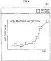
- Fig. 4 is a diagram showing an example of the screen display of the display unit of the roller bearing condition monitoring system according to the first embodiment.
- the horizontal axis represents the time t
- the vertical axis represents the maximum value of the amplitude of the pulse wave (amplitude value)
- the legend shows the identifying information of the roller bearing 2 in which a fault has occurred and the fault site.
- Fig. 4 shows the time change of the amplitude value of the pulse wave in the roller bearing 2.
- control unit 9 may also determine that a fault has occurred in the corresponding roller bearing 2 based on the amplitude value of the pulse wave in the roller bearing 2, and emit an alarm or output a report.
- the control unit 9 performs diagnosis of automatically determining that a fault has occurred at the corresponding site of the corresponding roller bearing 2, for example, when the amplitude value of the pulse wave exceeds a predetermined threshold, and displays the diagnostic result, for example, on the display screen of the display unit 10.
- Fig. 5 is a diagram showing an example of the diagnostic result of the roller bearing condition monitoring system according to the first embodiment.
- the control unit 9 records the diagnostic result of the roller bearing condition monitoring system 1 in a diagnostic result table TA1, which includes information in the respective columns of date/time, damaged bearing, damaged site, and damage level, and stores such information in the storage unit 17.
- the "damage level” shows the progress of the damage in multiple stages, for instance, such as "high”, “medium”, and “low” by determining the amplitude value based on a plurality of thresholds. Note that the format of saving the diagnostic result is not limited to a table.
- the record of the first line in Fig. 5 shows that the control unit 9 performed a diagnosis to the effect that a fault having an amplitude value of "a1” and a damage level of "low” occurred in the "outer ring" of the "A bearing” on "2018/12/1 13:00".
- control unit 9 performed a diagnosis to the effect that a fault having an amplitude value of "a4" and a damage level of "low” occurred in the "outer ring” of the "A bearing” and a fault having an amplitude value of "b4" and a damage level of "medium” occurred in the "inner ring” of the “B bearing” on "2018/12/1 13:30".
- the control unit 9 may also display, on the display screen of the display unit 10, the damage level recorded in the diagnostic result table TA1 in chronological order for each damaged site of the roller bearing 2 (inner ring 4, outer ring 5, and rolling element 6).
- a fault that occurred in the roller bearing 2 can be recognized from its initial stage, in which such fault will not immediately lead to an accident, and as such fault gradually becomes more serious.
- a device or the like including the roller bearing 2 to be monitored when the fault that occurred in the roller bearing 2 reaches a level that may soon lead to an accident, such device or the like can be immediately stopped. It is thereby possible to prevent the occurrence of an accident caused by the roller bearing 2 in operation.
- a vibration in the vicinity of the roller bearing 2 is measured at a low sampling rate and with a data length including the pulse wave caused by a fault, the pulse wave caused by the fault is searched from the measured vibration waveform based on theoretical generation cycles T1, T2, T3, and a maximum amplitude in the searched pulse wave is evaluated. It is thereby possible to obtain an amplitude value of a circular vibration at a high probability even at a low sampling rate, as well as capture a circular vibration of an outer ring of the bearing of a high frequent/high amplitude. In other words, a fault that occurred within the roller bearing 2 can be detected, even at a low sampling rate, at the same accuracy when measured based on high-speed sampling.
- the user can easily recognize which roller bearing 2 includes a fault and the degree of such fault based on changes in the amplitude value shown graphically on the display unit 10 or based on automatically emitted alarms or output reports.
- the degree of fault that occurred in the roller bearing 2 can be recognized according to how many times higher the amplitude value shown graphically on the display unit 10 has become in comparison to the initial stage when such fault first occurred, or according to how much time has elapsed from the initial stage when such fault first occurred.
- Fig. 6 is a functional block diagram of the roller bearing condition monitoring system according to the second embodiment.
- Fig. 7 is an overall processing flowchart of the roller bearing condition monitoring system according to the second embodiment.
- the roller bearing condition monitoring system 1B according to the second embodiment additionally comprises a frequency analyzing unit 11 in comparison to the roller bearing condition monitoring system 1 of the first embodiment.
- step S2a of performing frequency analysis is added between step S2 and step S3 in the flow of the first embodiment shown in Fig. 3 .
- step S1 and step S2 of Fig. 6 are the same as the processing of the first embodiment shown in Fig. 3 .
- the frequency analyzing unit 11 obtains a cycle T' as a reciprocal 1/f' of the detected peak frequency f'.
- step S3 which follows step S2a, the pulse wave search unit 15 in the roller bearing condition monitoring system 1B uses the cycle T' obtained by the frequency analyzing unit 11 and performs a pulse wave search in the same manner as the first embodiment. After the processing of step S3 is ended, the roller bearing condition monitoring system 1B performs the same processing as the first embodiment.
- a pulse wave is searched using the generation cycle T of the pulse wave that was theoretically obtained in advance. Nevertheless, actually, there are cases where the generation cycle of the pulse wave caused by the fault and the generation cycle T of the pulse wave stored in the storage unit 17 are different due to a measuring error of the rotation speed, or a slight slip of the rolling element.
- a cycle T' based on the peak frequency (1/T ⁇ f) detected within a predetermined vicinity of the frequency 1/T of the pulse wave, which is a reciprocal of the generation cycle T, is used in substitute for the generation cycle T of the pulse wave stored in the storage unit 17. It is thereby possible to maintain the accuracy of the pulse wave search even when there is a variation in the generation cycle of the pulse wave due to a measuring error of the rotation speed, or a slight slip of the rolling element.
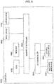
- Fig. 8 is a diagram showing the hardware configuration of the computer which realizes the roller bearing condition monitoring system.
- a CPU Central Processing Unit
- a memory 5400 such as a RAM (Random Access Memory)
- an input device 5600 for instance, keyboard, mouse, touch panel, etc.
- an output device 5700 for instance, video graphic card connected to an external display monitor
- the roller bearing condition monitoring system 1, 1B is realized by predetermined programs being read from an external storage device 5800 such as an SSD (Solid State Drive) or an HDD (Hard Disk Drive) via an I/O (Input/Output) controller 5200, and executed based on the coordination of the CPU 5300 and the memory 5400. Otherwise, the predetermined programs may also be acquired from an external computer through communication via a network interface 5100.
- an external storage device 5800 such as an SSD (Solid State Drive) or an HDD (Hard Disk Drive) via an I/O (Input/Output) controller 5200
- the predetermined programs may also be acquired from an external computer through communication via a network interface 5100.
- the present invention is not limited to the foregoing embodiments, and includes various modified examples.
- the foregoing embodiments were explained in detail in order to explain the present invention in an easy-to-understand manner, and the present invention is not necessarily limited to a type comprising all of the explained configurations.
- a part of the configuration of a certain embodiment may be replaced with the configuration of another embodiment, and the configuration of a certain embodiment may be added to the configuration of another embodiment.
- a part of the configuration of each embodiment can be added to, deleted from, replaced with, integrated with, or distributed to another configuration.
- the various types of processing shown in the embodiments may be distributed or integrated as appropriate pursuant to the processing efficiency or the mounting efficiency.
- 1, 1B roller bearing condition monitoring system
- 2 roller bearing
- 3 rotating shaft
- 4 inner ring
- 5 outer ring
- 6 rolling element
- 7 vibration measurement unit
- 8 A/D conversion unit
- 9 control unit
- 10 display unit
- 11 frequency analyzing unit
- 12 input I/F
- 13 measured value acquisition unit
- 14 envelope detection unit
- 15 pulse wave search unit
- 16 maximum pulse wave extraction unit
- 17 storage unit
- 18 output I/F
- 19 internal bus
- 50a display screen
- 5000: computer 5100: network interface
- 5400 memory
- 5600 input device
- 5700 output device
- 5800 external storage device
Landscapes
- Physics & Mathematics (AREA)
- General Physics & Mathematics (AREA)
- Acoustics & Sound (AREA)
- Testing Of Devices, Machine Parts, Or Other Structures Thereof (AREA)
- Measurement Of Mechanical Vibrations Or Ultrasonic Waves (AREA)
- Rolling Contact Bearings (AREA)
Abstract
Description
- The present invention relates to a condition monitoring system and a condition monitoring method of a roller bearing.
- For monitoring the condition of a roller bearing, a vibration acceleration sensor is often used as disclosed in
PTL 1,PTL 2, and NPTL 1. The standard condition monitoring method of a bearing based on vibration acceleration measurement is now explained with reference toFig. 9 . - If there is any fault on the inner ring track surface or the outer ring track surface of a roller bearing, a pulse wave is generated each time a rolling element passes by that fault. Moreover, if there is any fault on the rolling element, a pulse wave is generated each time that such fault collides with the inner ring track surface or the outer ring track surface based on the rotation of the rolling element.
- For example, in
Fig. 9(a) , if there is a fault on the outer ring track surface as shown in the cross section of the roller bearing in the left diagram, a periodic shock pulse wave is generated at timing t1 and timing t2 when the rolling element passes by the fault on the outer ring track surface as shown in the right diagram. These periodic shock pulse waves have a waveform as shown inFig. 9(b) , and excite the circular vibration of the outer ring of the bearing. This vibration frequency is a high frequency, and in certain cases it may be 10 kHz or higher. - Thus, foremost, a vibration acceleration sensor is placed around the roller bearing, and the circular vibration is measured at a sampling rate capable of capturing such circular vibration. Subsequently, an envelope is detected as shown in
Fig. 9(c) in relation to the obtained vibration waveform, and a pulse wave caused by the fault on the inside of the bearing is extracted. Subsequently, as shown inFig. 9(d) , the frequency that the rolling element passes by the fault and the amplitude value that is double the rotation frequency of the rolling element are evaluated based on FFT operation processing. An abnormality of the bearing is determined by monitoring the time change of the amplitude value as shown inFig. 9(e) . -
- [PTL 1]
Japanese Unexamined Patent Application Publication No. 2006-125976 - [PTL 2]
Japanese Unexamined Patent Application Publication No. 2012-42338 - [NPTL 1] Osami Matsushita et al. "[Part 2] Vibration from Rotating Machinery - Vibration Problem and Vibration Diagnosis of Real Machines", Coronasha, November 1, 2012
- Meanwhile, railways, construction machines, and wind generator systems use numerous roller bearings. Even if one of these numerous bearings is damaged in such machines and systems, the rotating shaft may become locked and this may lead to an accident. In order to introduce a monitoring system capable of covering the damage of numerous bearings, it is necessary to install numerous vibration sensors. Moreover, in order to detect a fault that occurred in a bearing, it is necessary to obtain a vibration waveform of a sufficient data length based on high-speed sampling in order to capture the circular vibration of the outer ring of the bearing. Furthermore, it is necessary to prepare numerous expensive AID converters for quickly digitizing large-capacity analog vibration waveforms. It is also necessary to increase the data storage capacity. Consequently, the cost of introducing a monitoring system will increase.
- An object of the present invention is to provide, at a low cost, a condition monitoring system for monitoring a roller bearing in order to resolve the foregoing problems.
- In order to achieve the foregoing object, the present invention provides a condition monitoring system of a roller bearing which supports a rotating shaft, comprising: a vibration measurement unit which measures a vibration of the roller bearing; an envelope detection unit which detects an envelope of an amplitude of a vibration waveform based on the vibration of the roller bearing measured with the vibration measurement unit; a pulse wave search unit which searches for a pulse wave of a cycle that matches a predetermined cycle based on a theoretical frequency of a vibration waveform, which is generated when the roller bearing is damaged, from the envelope detected with the envelope detection unit; and a pulse wave extraction unit which extracts a pulse wave of a maximum amplitude value from a pulse wave of a cycle that matches the predetermined cycle obtained from the search conducted by the pulse wave search unit, wherein condition monitoring of the roller bearing is performed based on the maximum amplitude value of the pulse wave extracted with the pulse wave extraction unit.
- Moreover, the present invention additionally provides a condition monitoring method of a roller bearing executed by a condition monitoring system of a roller bearing which supports a rotating shaft, comprising: a vibration measurement step of measuring a vibration of the roller bearing; an envelope detection step of detecting an envelope of an amplitude of a vibration waveform based on the vibration of the roller bearing measured with the vibration measurement unit; a pulse wave search step of searching for a pulse wave of a cycle that matches a predetermined cycle based on a theoretical frequency of a vibration waveform, which is generated when the roller bearing is damaged, from the envelope detected with the envelope detection unit; a pulse wave extraction step of extracting a pulse wave of a maximum amplitude value from a pulse wave of a cycle that matches the predetermined cycle obtained from the search conducted by the pulse wave search unit; and a condition monitoring step of performing condition monitoring of the roller bearing based on the maximum amplitude value of the pulse wave extracted in the pulse wave extraction step.
- According to the present invention, it is possible to detect an abnormality of a bearing with the same precision as high-speed sampling by performing sampling at a low speed and a short data length, and reduce the cost of introducing a condition monitoring system.
-
- [
Fig. 1 ]
Fig. 1 is an overall schematic configuration diagram of the roller bearing condition monitoring system according to the first embodiment. - [
Fig. 2 ]
Fig. 2 is a functional block diagram of the roller bearing condition monitoring system according to the first embodiment. - [
Fig. 3 ]
Fig. 3 is an overall processing flowchart of the roller bearing condition monitoring system according to the first embodiment. - [
Fig. 4 ]
Fig. 4 is a diagram showing an example of the screen display of the display unit of the roller bearing condition monitoring system according to the first embodiment. - [
Fig. 5 ]
Fig. 5 is a diagram showing an example of the diagnostic result of the roller bearing condition monitoring system according to the first embodiment. - [
Fig. 6 ]
Fig. 6 is a functional block diagram of the roller bearing condition monitoring system according to the second embodiment. - [
Fig. 7 ]
Fig. 7 is an overall processing flowchart of the roller bearing condition monitoring system according to the second embodiment. - [
Fig. 8 ]
Fig. 8 is a diagram showing the hardware configuration of the computer which realizes the roller bearing condition monitoring system. - [
Fig. 9 ]
Fig. 9 is a diagram explaining the diagnosis method of a general roller bearing condition monitoring system. - Embodiments of the present invention are now explained in detail with reference to the appended drawings. In the following explanation, the same reference numeral will be used to indicate the same or similar configurations or configurations having the same or similar function, and any subsequent explanation will be omitted. Moreover, the respective embodiments and respective modified examples may be partially or wholly combined within the technical scope of the present invention and within any scope that is consistent with such technical scope.
- In the present specification, the term "roller bearing" includes a rolling ball bearing comprising a cylindrical inner ring disposed so as to cover an outer peripheral surface of a rotating shaft, a cylindrical outer ring disposed concentrically so as to cover an outer peripheral surface of a cylindrical inner ring and be separated at a predetermined spacing radially outward from the outer peripheral surface of the inner ring, and a bearing housing disposed so as to cover an outer peripheral surface of an outer ring, wherein a plurality of spherical balls, as rolling elements, are disposed in a circumferential direction between the outer peripheral surface of the inner ring and the inner peripheral surface of the outer ring, and a rolling roller bearing in which a plurality of columnar rollers, as rolling elements, are disposed in a circumferential direction between the outer peripheral surface of the inner ring and the inner peripheral surface of the outer ring. The term "roller bearing" also include a deep groove bearing in which a plurality of arc-like deep grooves are formed in a circumferential direction and at a predetermined spacing on an outer peripheral surface of a cylindrical inner ring, wherein arc-like deep grooves are formed on an inner peripheral surface of a cylindrical outer ring at positions facing the deep grooves formed on the outer peripheral surface of the inner ring.
- The following embodiments can be applied to wind generator systems, construction machines, railways, elevators and other technical fields.
- The configuration of the roller bearing condition monitoring system according to the first embodiment is foremost explained with reference to
Fig. 1 andFig. 2 .Fig. 1 is an overall schematic configuration diagram of the roller bearing condition monitoring system according to the first embodiment.Fig. 2 is a functional block diagram of the roller bearing condition monitoring system according to the first embodiment. - As shown in
Fig. 1 , the roller bearingcondition monitoring system 1 includes at least adisplay unit 10, avibration measurement unit 7 such as a sensor for measuring a vibration of a roller bearing 2, anAID conversion unit 8 which converts a measured analog vibration waveform into a digital vibration waveform, and acontrol unit 9 which performs operation processing to the measured signals and graphically shows the results and monitors the condition of the roller bearing. - The roller bearing 2 includes, as shown in
Fig. 1 , a cylindricalinner ring 4 disposed so as to cover an outer peripheral surface of a rotatingshaft 3 and which engages with the rotatingshaft 3, a cylindricalouter ring 5 disposed concentrically so as to cover an outer peripheral surface of the cylindricalinner ring 4 and be separated at a predetermined spacing radially outward from the outer peripheral surface of theinner ring 4, and a plurality ofrolling elements 6 disposed in a circumferential direction between the outer peripheral surface of theinner ring 4 and the inner peripheral surface of theouter ring 5 so as to be mutually separated at a predetermined spacing. Note thatFig. 1 shows a vertical cross section of theinner ring 4, theouter ring 5, and the rollingelements 6 of theroller bearing 2, and shows the part of therotating shaft 3 that engages with theroller bearing 2. Moreover, inFig. 1 , the bearing housing that covers the outer peripheral surface of theouter ring 5 has been omitted. - In
Fig. 1 , while one set of theroller bearing 2 and thevibration measurement unit 7 is illustrated for the sake of convenience in explaining the present invention, the roller bearingcondition monitoring system 1 may also include multiple sets of theroller bearing 2 and thevibration measurement unit 7. In the foregoing case, the roller bearingcondition monitoring system 1 is able to identify therespective roller bearings 2. - As shown in
Fig. 2 , the roller bearingcondition monitoring system 1 of this embodiment includes avibration measurement unit 7, an A/D conversion unit 8, acontrol unit 9, and adisplay unit 10 such as an LCD (Liquid Crystal Display), an LED (Light Emitting Diode) display or an organic EL (Electro Luminescence) display. - The
control unit 9 includes an input I/F 12, a measuredvalue acquisition unit 13, anenvelope detection unit 14, a pulsewave search unit 15, a maximum pulsewave extraction unit 16, astorage unit 17, and an output I/F 18. These components are mutually connected via aninternal bus 19. - The input I/
F 12 accepts the input of measured values of the vibration waveform measured with thevibration measurement unit 7 and thereafter digitized with the A/D conversion unit 8, and of input values of operation data (for example, rotation frequency Ω of the roller bearing 2). - The measured
value acquisition unit 13 acquires, via the input I/F 12, the measured values including the vibration waveform measured with thevibration measurement unit 7 and thereafter digitized with the A/D conversion unit 8. This acquired value is transferred to theenvelope detection unit 14 via theinternal bus 19, and stored in a predetermined storage area of thestorage unit 17. Moreover, the measuredvalue acquisition unit 13 converts the measured rotation speed of theroller bearing 2 into rotation speed data by using, for example, an encoder (not shown) or the like, transfers the converted rotation speed data to the pulsewave search unit 15 via theinternal bus 19, and stores such converted rotation speed data in a predetermined storage area of thestorage unit 17. - The
envelope detection unit 14 performs absolute value rectification to the digital vibration waveform acquired with the measuredvalue acquisition unit 13. - The pulse
wave search unit 15 searches for a pulse wave which is generated in a theoretically obtained generation cycle T of the pulse wave stored in thestorage unit 17 from the digital vibration waveform that underwent the absolute value rectification performed by theenvelope detection unit 14. The generation cycle T of the pulse wave will be explained later. - The maximum pulse
wave extraction unit 16 extracts a pulse wave in which the amplitude becomes maximum from the pulse wave searched with the pulsewave search unit 15. The maximum pulsewave extraction unit 16 obtains the amplitude value of each of the extracted pulse waves and transfers the results to the maximum pulsewave extraction unit 16 via theinternal bus 19. - The maximum pulse
wave extraction unit 16 obtains a maximum value of the amplitude among the pulse waves transferred from the pulsewave search unit 15 via theinternal bus 19, and stores the obtained maximum value in a predetermined storage area of thestorage unit 17 via theinternal bus 19. The maximum value of the amplitude obtained with the maximum pulsewave extraction unit 16 is displayed on a screen of thedisplay unit 10 via the output I/F 18. - The
storage unit 17 stores the generation cycle T of the pulse wave of the vibration, which occurs when a fault occurs in theroller bearing 2, theoretically obtained from the specification of theroller bearing 2. Thestorage unit 17 stores the generation cycle T of the pulse wave for eachroller bearing 2 having the same specification. - Here, as the types of the generation cycle T of the pulse wave of the vibration stored in the
storage unit 17, there are a generation cycle T1 of the pulse wave when a fault occurs in theinner ring 4, a generation cycle T2 of the pulse wave when a fault occurs in theouter ring 5, and a generation cycle T3 of the pulse wave when a fault occurs in the rollingelement 6. - The generation cycle T1 of the pulse wave is, when a fault occurs in the
inner ring 4, a reciprocal of a frequency f1 of the pulse wave which is generated when the rollingelement 6 passes by that fault calculated based on Formula (1) below. The frequency f1 of the pulse wave is also referred to as an inner ring rolling element passing frequency. - The generation cycle T2 of the pulse wave is, when a fault occurs in the
outer ring 5, a reciprocal of a frequency f2 of the pulse wave which is generated when the rollingelement 6 passes by that fault calculated based on Formula (2) below. The frequency f1 of the pulse wave is also referred to as an outer ring rolling element passing frequency. - The generation cycle T3 of the pulse wave is a reciprocal of a frequency f3 of the pulse wave which is generated when a fault occurs in the rolling
element 6 and the fault collides at two locations; specifically, with theinner ring 4 and with theouter ring 5, calculated based on Formula (3) below. The frequency f3 of the pulse wave is a frequency that is double the rotation frequency of the rollingelement 6.


- Here, the respective parameters in Formula (1) to Formula (3) above are as follows; specifically, P: pitch diameter [m] of the bearing, B: diameter [m] of the rolling element, a: contact angle [deg] (for a roller bearing, α = 0), N: number of rolling elements, and Ω: rotation frequency [Hz] of the
roller bearing 2. - Note that the
envelope detection unit 14, the pulsewave search unit 15, and the maximum pulsewave extraction unit 16 are realized, for example, by a storage device such as a ROM which stores various programs or a RAM which temporarily stores data in the course of performing operations or in the course of executing programs, or by a processor such as a CPU which executes various programs stored in a ROM. - The processing performed in the roller bearing condition monitoring system according to the first embodiment is now explained with reference to
Fig. 3. Fig. 3 is an overall processing flowchart of the roller bearing condition monitoring system according to the first embodiment. The overall processing of the roller bearing condition monitoring system according to the first embodiment is executed based on a predetermined execution trigger. - As examples of the execution trigger of the overall processing of the roller bearing condition monitoring system, considered may be the following. For example, if the monitoring target of the roller bearing condition is a railway, the execution trigger may be that the train has passed a predetermined route, or that the train has reached a predetermined running speed (steady speed, etc.). Moreover, if the monitoring target of the roller bearing condition is a windmill, the execution trigger may be that the windmill has reached a steady operation (steady output or steady rotation speed, etc.). Otherwise, the overall processing of the roller bearing condition monitoring system may be executed in predetermined time intervals after reaching such steady operation. The roller bearing condition monitoring condition can be made constant and the monitoring accuracy can be ensured by executing the overall processing of the roller bearing condition monitoring system based on a predetermined execution trigger.
- In
Fig. 3 , the vibration measurement result according to this embodiment is shown with a solid line, and the vibration measurement result of the comparative example is shown with a broken line. In this embodiment, the vibration is sampled at a sampling rate that is lower than a predetermined rate, and, in the comparative example, the vibration is sampled at a sampling rate that is higher than a predetermined rate. - Foremost, in step S1, the
vibration measurement unit 7 in the roller bearingcondition monitoring system 1 measures the vibration in the vicinity of theroller bearing 2 using a vibration acceleration sensor at a sampling rate that is lower than a predetermined rate. TheAID conversion unit 8 digitizes the measured analog vibration waveform data. - Next, in step S2, the
envelope detection unit 14 in the roller bearingcondition monitoring system 1 performs absolute value rectification to the vibration waveform data acquired with the measuredvalue acquisition unit 13 and digitized with theAID conversion unit 8. The term "absolute value rectification" means the generation of a waveform of the amplitude of the vibration waveform. - Next, in step S3, the pulse
wave search unit 15 searches for a pulse wave which is generated in the theoretically obtained generation cycle T of the pulse wave stored in thestorage unit 17 from the waveform that underwent the absolute value rectification in step S2. Specifically, the pulsewave search unit 15 divides the time-series digital vibration waveform in the generation cycle Tj (j = 1, 2, 3) of the pulse wave, and obtains the maximum value of the amplitude value in each section and the generation time interval thereof. The pulsewave search unit 15 compares the obtained generation time interval of the pulse wave and the generation cycle Tj (j = 1, 2, 3) of the pulse wave stored in thestorage unit 17, and, if they match, it is determined that a fault has occurred at the corresponding site. - For example, the time-series digital vibration waveform is divided in the generation cycle T1 of the pulse wave, the maximum value of the amplitude value in each section and the generation time interval thereof are obtained, and, when the obtained generation time interval D and the generation cycle T1 match, it can be determined that a fault has occurred in the inner ring of the
roller bearing 2. Similarly, in the case of the generation cycle T2 of the pulse wave, it can be determined that a fault has occurred in the outer ring of theroller bearing 2 and, in the case of the generation cycle T3 of the pulse wave, it can be determined that a fault has occurred in the rolling element of theroller bearing 2. - Next, in step S4, in order to evaluate the level of damage of the fault site identified with the pulse
wave search unit 15, the maximum pulsewave extraction unit 16 extracts the pulse wave in which the amplitude becomes maximum among the searched pulse waves, and obtains the amplitude value thereof. Once the execution of step S4 is completed, processing of the roller bearingcondition monitoring system 1 is ended. - The
control unit 9 stores the fault site obtained based on the foregoing processing of step S1 to step S4, the maximum value of the amplitude of the pulse wave, and the rotation speed data, for example, in a predetermined storage area of thestorage unit 17 upon linking such information for each time t that such information was acquired. - The
control unit 9 shows, as numerical values or a graph, the maximum value of the amplitude of the pulse wave for each time t obtained based on the overall processing flow of the roller bearingcondition monitoring system 1 described above, and outputs such information on adisplay screen 50a of thedisplay unit 10 via the output I/F 18.Fig. 4 is a diagram showing an example of the screen display of the display unit of the roller bearing condition monitoring system according to the first embodiment. - As shown in
Fig. 4 , on thedisplay screen 50a, which is a GUI or the like, the horizontal axis represents the time t, the vertical axis represents the maximum value of the amplitude of the pulse wave (amplitude value), and the legend shows the identifying information of theroller bearing 2 in which a fault has occurred and the fault site.Fig. 4 shows the time change of the amplitude value of the pulse wave in theroller bearing 2. On thedisplay screen 50a, it is also possible to display a display attribute that is different from the plot display of the amplitude value at each time according to the size of the amplitude value, and show the progress of the damage at multiple stages. - Moreover, the
control unit 9 may also determine that a fault has occurred in thecorresponding roller bearing 2 based on the amplitude value of the pulse wave in theroller bearing 2, and emit an alarm or output a report. Thecontrol unit 9 performs diagnosis of automatically determining that a fault has occurred at the corresponding site of thecorresponding roller bearing 2, for example, when the amplitude value of the pulse wave exceeds a predetermined threshold, and displays the diagnostic result, for example, on the display screen of thedisplay unit 10. - Moreover,
Fig. 5 is a diagram showing an example of the diagnostic result of the roller bearing condition monitoring system according to the first embodiment. As illustrated inFig. 5 , thecontrol unit 9 records the diagnostic result of the roller bearingcondition monitoring system 1 in a diagnostic result table TA1, which includes information in the respective columns of date/time, damaged bearing, damaged site, and damage level, and stores such information in thestorage unit 17. The "damage level" shows the progress of the damage in multiple stages, for instance, such as "high", "medium", and "low" by determining the amplitude value based on a plurality of thresholds. Note that the format of saving the diagnostic result is not limited to a table. - For example, the record of the first line in
Fig. 5 shows that thecontrol unit 9 performed a diagnosis to the effect that a fault having an amplitude value of "a1" and a damage level of "low" occurred in the "outer ring" of the "A bearing" on "2018/12/1 13:00". Moreover, for example, the record of the fourth line and the fifth line inFig. 5 shows that thecontrol unit 9 performed a diagnosis to the effect that a fault having an amplitude value of "a4" and a damage level of "low" occurred in the "outer ring" of the "A bearing" and a fault having an amplitude value of "b4" and a damage level of "medium" occurred in the "inner ring" of the "B bearing" on "2018/12/1 13:30". Thecontrol unit 9 may also display, on the display screen of thedisplay unit 10, the damage level recorded in the diagnostic result table TA1 in chronological order for each damaged site of the roller bearing 2 (inner ring 4,outer ring 5, and rolling element 6). - As described above, in a device or the like including the
roller bearing 2 to be monitored, a fault that occurred in theroller bearing 2 can be recognized from its initial stage, in which such fault will not immediately lead to an accident, and as such fault gradually becomes more serious. Thus, in a device or the like including theroller bearing 2 to be monitored, it is possible to perform maintenance at a stage when the fault that occurred in theroller bearing 2 reaches a predetermined level, which is less than the level that will immediately lead to an accident. Moreover, in a device or the like including theroller bearing 2 to be monitored, when the fault that occurred in theroller bearing 2 reaches a level that may soon lead to an accident, such device or the like can be immediately stopped. It is thereby possible to prevent the occurrence of an accident caused by theroller bearing 2 in operation. - In this embodiment, a vibration in the vicinity of the
roller bearing 2 is measured at a low sampling rate and with a data length including the pulse wave caused by a fault, the pulse wave caused by the fault is searched from the measured vibration waveform based on theoretical generation cycles T1, T2, T3, and a maximum amplitude in the searched pulse wave is evaluated. It is thereby possible to obtain an amplitude value of a circular vibration at a high probability even at a low sampling rate, as well as capture a circular vibration of an outer ring of the bearing of a high frequent/high amplitude. In other words, a fault that occurred within theroller bearing 2 can be detected, even at a low sampling rate, at the same accuracy when measured based on high-speed sampling. - Consequently, an expensive A/D converter compatible with high-speed sampling is not required, the data length including the pulse wave caused by the fault can be suppressed in comparison to a case based on high-speed sampling, the capacity of the
storage unit 17 can be reduced even when monitoring the condition of a plurality ofroller bearings 2 and, therefore, the introduction cost of the roller bearingcondition monitoring system 1 can be reduced. - Moreover, the user can easily recognize which
roller bearing 2 includes a fault and the degree of such fault based on changes in the amplitude value shown graphically on thedisplay unit 10 or based on automatically emitted alarms or output reports. For example, the degree of fault that occurred in theroller bearing 2 can be recognized according to how many times higher the amplitude value shown graphically on thedisplay unit 10 has become in comparison to the initial stage when such fault first occurred, or according to how much time has elapsed from the initial stage when such fault first occurred. - Thus, when it is predicted that a serious accident may occur soon based on the degree of the fault, it is possible to immediately stop the device or the like including the
roller bearing 2 to be monitored and thereby prevent such accident from happening. Moreover, unnecessary maintenance work can be reduced by performing maintenance according to the condition of theroller bearing 2. -
Fig. 6 is a functional block diagram of the roller bearing condition monitoring system according to the second embodiment.Fig. 7 is an overall processing flowchart of the roller bearing condition monitoring system according to the second embodiment. The roller bearingcondition monitoring system 1B according to the second embodiment additionally comprises afrequency analyzing unit 11 in comparison to the roller bearingcondition monitoring system 1 of the first embodiment. Moreover, in the overall processing of the roller bearing condition monitoring system according to the second embodiment, step S2a of performing frequency analysis is added between step S2 and step S3 in the flow of the first embodiment shown inFig. 3 . - The processing of step S1 and step S2 of
Fig. 6 is the same as the processing of the first embodiment shown inFig. 3 . - In step S2a which follows step S2 of
Fig. 6 , thefrequency analyzing unit 11 in the roller bearingcondition monitoring system 1B performs frequency analysis such as FFT to the digital vibration waveform on the time axis that underwent absolute value rectification performed by theenvelope detection unit 14. Subsequently, thefrequency analyzing unit 11 detects a peak frequency which is one frequency within a predetermined vicinity among the frequencies fj (j = 1, 2, 3) (= 1/T) theoretically obtained in Formulas (1) to (3) above and in which the amplitude has peaked. The peak frequency f' within the predetermined vicinity satisfies, for example, f = fj±Δf = 1/T±Δf. However, Δf is a predetermined value. Furthermore, thefrequency analyzing unit 11 obtains a cycle T' as a reciprocal 1/f' of the detected peak frequency f'. - In step S3 which follows step S2a, the pulse
wave search unit 15 in the roller bearingcondition monitoring system 1B uses the cycle T' obtained by thefrequency analyzing unit 11 and performs a pulse wave search in the same manner as the first embodiment. After the processing of step S3 is ended, the roller bearingcondition monitoring system 1B performs the same processing as the first embodiment. - In the first embodiment, a pulse wave is searched using the generation cycle T of the pulse wave that was theoretically obtained in advance. Nevertheless, actually, there are cases where the generation cycle of the pulse wave caused by the fault and the generation cycle T of the pulse wave stored in the
storage unit 17 are different due to a measuring error of the rotation speed, or a slight slip of the rolling element. Thus, in the second embodiment, upon performing a pulse wave search, a cycle T' based on the peak frequency (1/T±Δf) detected within a predetermined vicinity of thefrequency 1/T of the pulse wave, which is a reciprocal of the generation cycle T, is used in substitute for the generation cycle T of the pulse wave stored in thestorage unit 17. It is thereby possible to maintain the accuracy of the pulse wave search even when there is a variation in the generation cycle of the pulse wave due to a measuring error of the rotation speed, or a slight slip of the rolling element. -
Fig. 8 is a diagram showing the hardware configuration of the computer which realizes the roller bearing condition monitoring system. In acomputer 5000 which realizes the roller bearingcondition monitoring system memory 5400 such as a RAM (Random Access Memory), an input device 5600 (for instance, keyboard, mouse, touch panel, etc.), and an output device 5700 (for instance, video graphic card connected to an external display monitor) are mutually connected via amemory controller 5500. - In the
computer 5000, the roller bearingcondition monitoring system external storage device 5800 such as an SSD (Solid State Drive) or an HDD (Hard Disk Drive) via an I/O (Input/Output)controller 5200, and executed based on the coordination of theCPU 5300 and thememory 5400. Otherwise, the predetermined programs may also be acquired from an external computer through communication via anetwork interface 5100. - The present invention is not limited to the foregoing embodiments, and includes various modified examples. For example, the foregoing embodiments were explained in detail in order to explain the present invention in an easy-to-understand manner, and the present invention is not necessarily limited to a type comprising all of the explained configurations. Moreover, a part of the configuration of a certain embodiment may be replaced with the configuration of another embodiment, and the configuration of a certain embodiment may be added to the configuration of another embodiment. Furthermore, a part of the configuration of each embodiment can be added to, deleted from, replaced with, integrated with, or distributed to another configuration. In addition, the various types of processing shown in the embodiments may be distributed or integrated as appropriate pursuant to the processing efficiency or the mounting efficiency.
- 1, 1B: roller bearing condition monitoring system, 2: roller bearing, 3: rotating shaft, 4: inner ring, 5: outer ring, 6: rolling element, 7: vibration measurement unit, 8: A/D conversion unit, 9: control unit, 10: display unit, 11: frequency analyzing unit, 12: input I/F, 13: measured value acquisition unit, 14: envelope detection unit, 15: pulse wave search unit, 16: maximum pulse wave extraction unit, 17: storage unit, 18: output I/F, 19: internal bus, 50a: display screen, 5000: computer, 5100: network interface, 5200: controller, 5400: memory, 5500: memory controller, 5600: input device, 5700: output device, 5800: external storage device
Claims (12)
- A condition monitoring system of a roller bearing which supports a rotating shaft, comprising:a vibration measurement unit which measures a vibration of the roller bearing;an envelope detection unit which detects an envelope of an amplitude of a vibration waveform based on the vibration of the roller bearing measured with the vibration measurement unit;a pulse wave search unit which searches for a pulse wave of a cycle that matches a predetermined cycle based on a theoretical frequency of a vibration waveform, which is generated when the roller bearing is damaged, from the envelope detected with the envelope detection unit; anda pulse wave extraction unit which extracts a pulse wave of a maximum amplitude value from a pulse wave of a cycle that matches the predetermined cycle obtained from the search conducted by the pulse wave search unit,wherein condition monitoring of the roller bearing is performed based on the maximum amplitude value of the pulse wave extracted with the pulse wave extraction unit.
- The condition monitoring system according to claim 1,
wherein the predetermined cycle is a reciprocal of the theoretical frequency. - The condition monitoring system according to claim 1, further comprising:a frequency analyzing unit which performs frequency analysis of the envelope detected with the envelope detection unit,wherein the predetermined cycle is a reciprocal of a peak frequency within a predetermined vicinity of the theoretical frequency in the envelope that underwent the frequency analysis performed by the frequency analyzing unit.
- The condition monitoring system according to any one of claims 1 to 3,
wherein the vibration measurement unit measures the vibration of the roller bearing based on low-speed sampling in which a sampling rate is lower than a predetermined rate. - The condition monitoring system according to any one of claims 1 to 4,
wherein the theoretical frequency is a first frequency of a pulse wave which is generated when the rolling element passes by a fault that occurred to an inner ring in the roller bearing, a second frequency of a pulse wave which is generated when the rolling element passes by a fault that occurred to an outer ring in the roller bearing, and a third frequency which is double a rotation frequency of the rolling element of the roller bearing. - The condition monitoring system according to claim 5,
wherein whether the inner ring, the outer ring or the rolling element in the roller bearing has been damaged is determined based on whether a cycle of a pulse wave obtained from the search conducted by the pulse wave search unit matches a first cycle based on the first frequency, a second cycle based on the second frequency or a third cycle based on the third frequency. - The condition monitoring system according to any one of claims 1 to 6,
wherein a time change of the maximum amplitude value of the pulse wave extracted with the pulse wave extraction unit is displayed on a display unit. - The condition monitoring system according to any one of claims 1 to 7,
wherein it is determined that the roller bearing has been damaged when the maximum amplitude value of the pulse wave extracted with the pulse wave extraction unit exceeds a predetermined threshold. - The condition monitoring system according to claim 8,
wherein information indicating that the roller bearing has been damaged is output. - The condition monitoring system according to any one of claims 1 to 9,
wherein a damage level of the roller bearing is diagnosed based on the maximum amplitude value of the pulse wave extracted with the pulse wave extraction unit. - The condition monitoring system according to any one of claims 1 to 9,
wherein the vibration measurement unit measures the vibration of the roller bearing at a timing that a device comprising the roller bearing enters a predetermined operating state, or in predetermined time intervals after the device enters the predetermined operating state. - A condition monitoring method of a roller bearing executed by a condition monitoring system of a roller bearing which supports a rotating shaft, comprising:a vibration measurement step of measuring a vibration of the roller bearing;an envelope detection step of detecting an envelope of an amplitude of a vibration waveform based on the vibration of the roller bearing measured with the vibration measurement unit;a pulse wave search step of searching for a pulse wave of a cycle that matches a predetermined cycle based on a theoretical frequency of a vibration waveform, which is generated when the roller bearing is damaged, from the envelope detected with the envelope detection unit;a pulse wave extraction step of extracting a pulse wave of a maximum amplitude value from a pulse wave of a cycle that matches the predetermined cycle obtained from the search conducted by the pulse wave search unit; anda condition monitoring step of performing condition monitoring of the roller bearing based on the maximum amplitude value of the pulse wave extracted in the pulse wave extraction step.
Applications Claiming Priority (2)
| Application Number | Priority Date | Filing Date | Title |
|---|---|---|---|
| JP2019042712A JP7155049B2 (en) | 2019-03-08 | 2019-03-08 | Rolling Bearing Condition Monitoring System and Condition Monitoring Method |
| PCT/JP2019/045156 WO2020183797A1 (en) | 2019-03-08 | 2019-11-18 | Rolling bearing status monitoring system and status monitoring method |
Publications (3)
| Publication Number | Publication Date |
|---|---|
| EP3936849A1 true EP3936849A1 (en) | 2022-01-12 |
| EP3936849A4 EP3936849A4 (en) | 2022-11-30 |
| EP3936849B1 EP3936849B1 (en) | 2025-09-17 |
Family
ID=72354009
Family Applications (1)
| Application Number | Title | Priority Date | Filing Date |
|---|---|---|---|
| EP19919171.9A Active EP3936849B1 (en) | 2019-03-08 | 2019-11-18 | Rolling bearing status monitoring system and status monitoring method |
Country Status (3)
| Country | Link |
|---|---|
| EP (1) | EP3936849B1 (en) |
| JP (1) | JP7155049B2 (en) |
| WO (1) | WO2020183797A1 (en) |
Families Citing this family (3)
| Publication number | Priority date | Publication date | Assignee | Title |
|---|---|---|---|---|
| JP7503527B2 (en) * | 2021-07-14 | 2024-06-20 | 株式会社神戸製鋼所 | Rolling bearing abnormality detection device and rolling bearing abnormality detection method |
| JP7398420B2 (en) * | 2021-11-12 | 2023-12-14 | Thk株式会社 | Monitoring system |
| CN114091211A (en) * | 2021-12-06 | 2022-02-25 | 东北大学 | Cold rolling mill vibration prediction and early warning method based on data driving |
Family Cites Families (17)
| Publication number | Priority date | Publication date | Assignee | Title |
|---|---|---|---|---|
| JPS52123679A (en) * | 1976-04-09 | 1977-10-18 | Koyo Seiko Co | Apparatus for checking for defectiveness of bearing |
| JPS605893B2 (en) * | 1976-04-09 | 1985-02-14 | 光洋精工株式会社 | Bearing abnormality monitoring device |
| JP3373718B2 (en) * | 1996-03-21 | 2003-02-04 | 松下電工株式会社 | Bearing damage detection method |
| US5852793A (en) * | 1997-02-18 | 1998-12-22 | Dme Corporation | Method and apparatus for predictive diagnosis of moving machine parts |
| JP2000171351A (en) * | 1998-12-07 | 2000-06-23 | Ntn Corp | Acoustic inspecting device for rolling bearing |
| DE19938721A1 (en) * | 1999-08-16 | 2001-02-22 | Busch Dieter & Co Prueftech | Method and device for determining damage to cyclically moving machine elements |
| EP1211500B1 (en) * | 2000-12-01 | 2009-09-02 | Nsk Ltd | Rolling bearing apparatus with sensor |
| JP2006125976A (en) | 2004-10-28 | 2006-05-18 | Nsk Ltd | Abnormality diagnosis system for mechanical equipment |
| KR101429952B1 (en) * | 2008-01-30 | 2014-08-13 | 제이에프이 어드밴테크 가부시키가이샤 | Diagnostic system for bearing |
| US20100332186A1 (en) * | 2009-06-30 | 2010-12-30 | Wilson Kevin W | Probabilistic Estimation of a Time Interval Between Periodic Events Disturbing a Signal |
| JP5428994B2 (en) * | 2010-03-26 | 2014-02-26 | 新日鐵住金株式会社 | Anomaly diagnosis method, apparatus and program for machine equipment |
| CN102269655B (en) * | 2010-06-04 | 2014-12-17 | 北京化工大学 | Method for diagnosing bearing fault |
| JP2012042338A (en) | 2010-08-19 | 2012-03-01 | Ntn Corp | Roller bearing abnormality diagnosis apparatus and gear abnormality diagnosis apparatus |
| DE102011055523A1 (en) * | 2011-09-09 | 2013-03-14 | Christoph Höweler | Method for vibration analysis of e.g. bearing element, involves interpreting measurement values, which exceed predetermined threshold value, as oscillation pulse, and processing measurement values by algorithm |
| CN102866010B (en) * | 2012-09-28 | 2015-02-04 | 苏州大学 | Method for filtering spectral kurtosis of signal and relevant device |
| EP3029449A4 (en) * | 2013-08-01 | 2017-03-15 | NTN Corporation | Bearing-device vibration analysis method, bearing-device vibration analysis device, and rolling-bearing status-monitoring device |
| CN103884506B (en) * | 2014-03-25 | 2019-07-23 | 福建省工业设备安装有限公司 | Production equipment on-line monitoring and fault diagnosis system and method based on wireless network |
-
2019
- 2019-03-08 JP JP2019042712A patent/JP7155049B2/en active Active
- 2019-11-18 EP EP19919171.9A patent/EP3936849B1/en active Active
- 2019-11-18 WO PCT/JP2019/045156 patent/WO2020183797A1/en not_active Ceased
Also Published As
| Publication number | Publication date |
|---|---|
| WO2020183797A1 (en) | 2020-09-17 |
| EP3936849B1 (en) | 2025-09-17 |
| JP2020144072A (en) | 2020-09-10 |
| EP3936849A4 (en) | 2022-11-30 |
| JP7155049B2 (en) | 2022-10-18 |
Similar Documents
| Publication | Publication Date | Title |
|---|---|---|
| EP3936849B1 (en) | Rolling bearing status monitoring system and status monitoring method | |
| Saruhan et al. | Vibration analysis of rolling element bearings defects | |
| CN109883703B (en) | A fan bearing health monitoring and diagnosis method based on coherent cepstrum analysis of vibration signals | |
| JP6038347B2 (en) | Abnormal sound diagnosis device | |
| EP2940449A1 (en) | Bearing device vibration analysis method, bearing device vibration analysis device, and rolling bearing status monitoring device | |
| CA2874991A1 (en) | Methods and apparatuses for defect diagnosis in a mechanical system | |
| EP3029449A1 (en) | Bearing-device vibration analysis method, bearing-device vibration analysis device, and rolling-bearing status-monitoring device | |
| US20130107036A1 (en) | Inspection system and method for correlating data from sensors and visual displays | |
| JP5948418B2 (en) | Abnormal sound detection system | |
| CN114813124B (en) | Method and device for monitoring bearing faults | |
| US20140058615A1 (en) | Fleet anomaly detection system and method | |
| CN105738136B (en) | A kind of unit exception detection method and device | |
| US20140214363A1 (en) | Fault frequency set detection system and method | |
| EP3674827A1 (en) | Monitoring target selecting device, monitoring target selecting method and program | |
| CN116304848B (en) | A rolling bearing fault diagnosis system and method | |
| CN119509975A (en) | Main bearing fault warning method and electronic equipment | |
| KR20260034631A (en) | A System and Method for Diagnosing Motor Faults by Analyzing the Time-Varying Changes of Fourier Transformed Values Using Artificial Intelligence | |
| KR102666166B1 (en) | Diagnostic method for bearing faults | |
| US10908014B2 (en) | Detecting rotor anomalies during transient speed operations | |
| CN114137063A (en) | Rolling bearing fault diagnosis method based on weak magnetic detection | |
| KR101482511B1 (en) | Diagnosis System and Method of Bearing Defect by Phase Lag and Data Dispersion Shape Factor | |
| WO2021256956A1 (en) | System and method of field inspection for defects in bearings of rotary equipment | |
| RU2670771C9 (en) | Method for determining contact character of blade of rotating wheel with body of turbomachine | |
| JP2017060333A (en) | Abnormality diagnosis method for semiconductor power conversion device, abnormality diagnosis device, abnormality diagnosis program and semiconductor power conversion device having abnormality diagnosis function | |
| JP2021011371A (en) | Diagnostic device, diagnostic system, and diagnostic method |
Legal Events
| Date | Code | Title | Description |
|---|---|---|---|
| STAA | Information on the status of an ep patent application or granted ep patent |
Free format text: STATUS: THE INTERNATIONAL PUBLICATION HAS BEEN MADE |
|
| PUAI | Public reference made under article 153(3) epc to a published international application that has entered the european phase |
Free format text: ORIGINAL CODE: 0009012 |
|
| STAA | Information on the status of an ep patent application or granted ep patent |
Free format text: STATUS: REQUEST FOR EXAMINATION WAS MADE |
|
| 17P | Request for examination filed |
Effective date: 20211008 |
|
| AK | Designated contracting states |
Kind code of ref document: A1 Designated state(s): AL AT BE BG CH CY CZ DE DK EE ES FI FR GB GR HR HU IE IS IT LI LT LU LV MC MK MT NL NO PL PT RO RS SE SI SK SM TR |
|
| DAV | Request for validation of the european patent (deleted) | ||
| DAX | Request for extension of the european patent (deleted) | ||
| A4 | Supplementary search report drawn up and despatched |
Effective date: 20221027 |
|
| RIC1 | Information provided on ipc code assigned before grant |
Ipc: G01H 1/00 20060101ALI20221021BHEP Ipc: G01M 13/045 20190101AFI20221021BHEP |
|
| STAA | Information on the status of an ep patent application or granted ep patent |
Free format text: STATUS: EXAMINATION IS IN PROGRESS |
|
| 17Q | First examination report despatched |
Effective date: 20231109 |
|
| GRAP | Despatch of communication of intention to grant a patent |
Free format text: ORIGINAL CODE: EPIDOSNIGR1 |
|
| STAA | Information on the status of an ep patent application or granted ep patent |
Free format text: STATUS: GRANT OF PATENT IS INTENDED |
|
| INTG | Intention to grant announced |
Effective date: 20250605 |
|
| GRAS | Grant fee paid |
Free format text: ORIGINAL CODE: EPIDOSNIGR3 |
|
| GRAA | (expected) grant |
Free format text: ORIGINAL CODE: 0009210 |
|
| STAA | Information on the status of an ep patent application or granted ep patent |
Free format text: STATUS: THE PATENT HAS BEEN GRANTED |
|
| AK | Designated contracting states |
Kind code of ref document: B1 Designated state(s): AL AT BE BG CH CY CZ DE DK EE ES FI FR GB GR HR HU IE IS IT LI LT LU LV MC MK MT NL NO PL PT RO RS SE SI SK SM TR |
|
| REG | Reference to a national code |
Ref country code: GB Ref legal event code: FG4D |
|
| REG | Reference to a national code |
Ref country code: CH Ref legal event code: EP |
|
| REG | Reference to a national code |
Ref country code: DE Ref legal event code: R096 Ref document number: 602019075978 Country of ref document: DE |
|
| REG | Reference to a national code |
Ref country code: IE Ref legal event code: FG4D |
|
| PGFP | Annual fee paid to national office [announced via postgrant information from national office to epo] |
Ref country code: DE Payment date: 20251130 Year of fee payment: 7 |
|
| PG25 | Lapsed in a contracting state [announced via postgrant information from national office to epo] |
Ref country code: NO Free format text: LAPSE BECAUSE OF FAILURE TO SUBMIT A TRANSLATION OF THE DESCRIPTION OR TO PAY THE FEE WITHIN THE PRESCRIBED TIME-LIMIT Effective date: 20251217 |
|
| REG | Reference to a national code |
Ref country code: LT Ref legal event code: MG9D |
|
| PG25 | Lapsed in a contracting state [announced via postgrant information from national office to epo] |
Ref country code: FI Free format text: LAPSE BECAUSE OF FAILURE TO SUBMIT A TRANSLATION OF THE DESCRIPTION OR TO PAY THE FEE WITHIN THE PRESCRIBED TIME-LIMIT Effective date: 20250917 |
|
| PG25 | Lapsed in a contracting state [announced via postgrant information from national office to epo] |
Ref country code: HR Free format text: LAPSE BECAUSE OF FAILURE TO SUBMIT A TRANSLATION OF THE DESCRIPTION OR TO PAY THE FEE WITHIN THE PRESCRIBED TIME-LIMIT Effective date: 20250917 |
|
| PG25 | Lapsed in a contracting state [announced via postgrant information from national office to epo] |
Ref country code: GR Free format text: LAPSE BECAUSE OF FAILURE TO SUBMIT A TRANSLATION OF THE DESCRIPTION OR TO PAY THE FEE WITHIN THE PRESCRIBED TIME-LIMIT Effective date: 20251218 |
|
| PG25 | Lapsed in a contracting state [announced via postgrant information from national office to epo] |
Ref country code: SE Free format text: LAPSE BECAUSE OF FAILURE TO SUBMIT A TRANSLATION OF THE DESCRIPTION OR TO PAY THE FEE WITHIN THE PRESCRIBED TIME-LIMIT Effective date: 20250917 |
|
| REG | Reference to a national code |
Ref country code: NL Ref legal event code: MP Effective date: 20250917 |
|
| PG25 | Lapsed in a contracting state [announced via postgrant information from national office to epo] |
Ref country code: LV Free format text: LAPSE BECAUSE OF FAILURE TO SUBMIT A TRANSLATION OF THE DESCRIPTION OR TO PAY THE FEE WITHIN THE PRESCRIBED TIME-LIMIT Effective date: 20250917 |
|
| PG25 | Lapsed in a contracting state [announced via postgrant information from national office to epo] |
Ref country code: BG Free format text: LAPSE BECAUSE OF FAILURE TO SUBMIT A TRANSLATION OF THE DESCRIPTION OR TO PAY THE FEE WITHIN THE PRESCRIBED TIME-LIMIT Effective date: 20250917 |
|
| PG25 | Lapsed in a contracting state [announced via postgrant information from national office to epo] |
Ref country code: RS Free format text: LAPSE BECAUSE OF FAILURE TO SUBMIT A TRANSLATION OF THE DESCRIPTION OR TO PAY THE FEE WITHIN THE PRESCRIBED TIME-LIMIT Effective date: 20251217 |
|
| PG25 | Lapsed in a contracting state [announced via postgrant information from national office to epo] |
Ref country code: NL Free format text: LAPSE BECAUSE OF FAILURE TO SUBMIT A TRANSLATION OF THE DESCRIPTION OR TO PAY THE FEE WITHIN THE PRESCRIBED TIME-LIMIT Effective date: 20250917 |
|
| REG | Reference to a national code |
Ref country code: AT Ref legal event code: MK05 Ref document number: 1838648 Country of ref document: AT Kind code of ref document: T Effective date: 20250917 |
|
| PG25 | Lapsed in a contracting state [announced via postgrant information from national office to epo] |
Ref country code: SM Free format text: LAPSE BECAUSE OF FAILURE TO SUBMIT A TRANSLATION OF THE DESCRIPTION OR TO PAY THE FEE WITHIN THE PRESCRIBED TIME-LIMIT Effective date: 20250917 |
|
| PG25 | Lapsed in a contracting state [announced via postgrant information from national office to epo] |
Ref country code: ES Free format text: LAPSE BECAUSE OF FAILURE TO SUBMIT A TRANSLATION OF THE DESCRIPTION OR TO PAY THE FEE WITHIN THE PRESCRIBED TIME-LIMIT Effective date: 20250917 |
|
| PG25 | Lapsed in a contracting state [announced via postgrant information from national office to epo] |
Ref country code: AT Free format text: LAPSE BECAUSE OF FAILURE TO SUBMIT A TRANSLATION OF THE DESCRIPTION OR TO PAY THE FEE WITHIN THE PRESCRIBED TIME-LIMIT Effective date: 20250917 |
|
| PG25 | Lapsed in a contracting state [announced via postgrant information from national office to epo] |
Ref country code: IT Free format text: LAPSE BECAUSE OF FAILURE TO SUBMIT A TRANSLATION OF THE DESCRIPTION OR TO PAY THE FEE WITHIN THE PRESCRIBED TIME-LIMIT Effective date: 20250917 Ref country code: RO Free format text: LAPSE BECAUSE OF FAILURE TO SUBMIT A TRANSLATION OF THE DESCRIPTION OR TO PAY THE FEE WITHIN THE PRESCRIBED TIME-LIMIT Effective date: 20250917 |
|
| PG25 | Lapsed in a contracting state [announced via postgrant information from national office to epo] |
Ref country code: IS Free format text: LAPSE BECAUSE OF FAILURE TO SUBMIT A TRANSLATION OF THE DESCRIPTION OR TO PAY THE FEE WITHIN THE PRESCRIBED TIME-LIMIT Effective date: 20260117 |
|
| PG25 | Lapsed in a contracting state [announced via postgrant information from national office to epo] |
Ref country code: CZ Free format text: LAPSE BECAUSE OF FAILURE TO SUBMIT A TRANSLATION OF THE DESCRIPTION OR TO PAY THE FEE WITHIN THE PRESCRIBED TIME-LIMIT Effective date: 20250917 Ref country code: PT Free format text: LAPSE BECAUSE OF FAILURE TO SUBMIT A TRANSLATION OF THE DESCRIPTION OR TO PAY THE FEE WITHIN THE PRESCRIBED TIME-LIMIT Effective date: 20260119 |
|
| PG25 | Lapsed in a contracting state [announced via postgrant information from national office to epo] |
Ref country code: PL Free format text: LAPSE BECAUSE OF FAILURE TO SUBMIT A TRANSLATION OF THE DESCRIPTION OR TO PAY THE FEE WITHIN THE PRESCRIBED TIME-LIMIT Effective date: 20250917 |
|
| PG25 | Lapsed in a contracting state [announced via postgrant information from national office to epo] |
Ref country code: SK Free format text: LAPSE BECAUSE OF FAILURE TO SUBMIT A TRANSLATION OF THE DESCRIPTION OR TO PAY THE FEE WITHIN THE PRESCRIBED TIME-LIMIT Effective date: 20250917 Ref country code: EE Free format text: LAPSE BECAUSE OF FAILURE TO SUBMIT A TRANSLATION OF THE DESCRIPTION OR TO PAY THE FEE WITHIN THE PRESCRIBED TIME-LIMIT Effective date: 20250917 |