EP3936833A1 - Measurement control apparatus and measurement control method - Google Patents
Measurement control apparatus and measurement control method Download PDFInfo
- Publication number
- EP3936833A1 EP3936833A1 EP20767124.9A EP20767124A EP3936833A1 EP 3936833 A1 EP3936833 A1 EP 3936833A1 EP 20767124 A EP20767124 A EP 20767124A EP 3936833 A1 EP3936833 A1 EP 3936833A1
- Authority
- EP
- European Patent Office
- Prior art keywords
- acquisition unit
- feature quantity
- measurement control
- control apparatus
- sensor data
- Prior art date
- Legal status (The legal status is an assumption and is not a legal conclusion. Google has not performed a legal analysis and makes no representation as to the accuracy of the status listed.)
- Granted
Links
Images



Classifications
-
- A—HUMAN NECESSITIES
- A61—MEDICAL OR VETERINARY SCIENCE; HYGIENE
- A61B—DIAGNOSIS; SURGERY; IDENTIFICATION
- A61B5/00—Measuring for diagnostic purposes; Identification of persons
- A61B5/02—Detecting, measuring or recording for evaluating the cardiovascular system, e.g. pulse, heart rate, blood pressure or blood flow
- A61B5/024—Measuring pulse rate or heart rate
- A61B5/0245—Measuring pulse rate or heart rate by using sensing means generating electric signals, i.e. ECG signals
-
- A—HUMAN NECESSITIES
- A61—MEDICAL OR VETERINARY SCIENCE; HYGIENE
- A61B—DIAGNOSIS; SURGERY; IDENTIFICATION
- A61B5/00—Measuring for diagnostic purposes; Identification of persons
- A61B5/24—Detecting, measuring or recording bioelectric or biomagnetic signals of the body or parts thereof
- A61B5/316—Modalities, i.e. specific diagnostic methods
- A61B5/318—Heart-related electrical modalities, e.g. electrocardiography [ECG]
- A61B5/346—Analysis of electrocardiograms
- A61B5/349—Detecting specific parameters of the electrocardiograph cycle
- A61B5/352—Detecting R peaks, e.g. for synchronising diagnostic apparatus; Estimating R-R interval
-
- A—HUMAN NECESSITIES
- A61—MEDICAL OR VETERINARY SCIENCE; HYGIENE
- A61B—DIAGNOSIS; SURGERY; IDENTIFICATION
- A61B5/00—Measuring for diagnostic purposes; Identification of persons
- A61B5/72—Signal processing specially adapted for physiological signals or for diagnostic purposes
- A61B5/7225—Details of analogue processing, e.g. isolation amplifier, gain or sensitivity adjustment, filtering, baseline or drift compensation
-
- A—HUMAN NECESSITIES
- A61—MEDICAL OR VETERINARY SCIENCE; HYGIENE
- A61B—DIAGNOSIS; SURGERY; IDENTIFICATION
- A61B2560/00—Constructional details of operational features of apparatus; Accessories for medical measuring apparatus
- A61B2560/02—Operational features
- A61B2560/0204—Operational features of power management
- A61B2560/0209—Operational features of power management adapted for power saving
-
- A—HUMAN NECESSITIES
- A61—MEDICAL OR VETERINARY SCIENCE; HYGIENE
- A61B—DIAGNOSIS; SURGERY; IDENTIFICATION
- A61B2560/00—Constructional details of operational features of apparatus; Accessories for medical measuring apparatus
- A61B2560/02—Operational features
- A61B2560/0204—Operational features of power management
- A61B2560/0214—Operational features of power management of power generation or supply
-
- A—HUMAN NECESSITIES
- A61—MEDICAL OR VETERINARY SCIENCE; HYGIENE
- A61B—DIAGNOSIS; SURGERY; IDENTIFICATION
- A61B5/00—Measuring for diagnostic purposes; Identification of persons
- A61B5/24—Detecting, measuring or recording bioelectric or biomagnetic signals of the body or parts thereof
- A61B5/316—Modalities, i.e. specific diagnostic methods
- A61B5/318—Heart-related electrical modalities, e.g. electrocardiography [ECG]
- A61B5/346—Analysis of electrocardiograms
- A61B5/349—Detecting specific parameters of the electrocardiograph cycle
- A61B5/364—Detecting abnormal ECG interval, e.g. extrasystoles, ectopic heartbeats
Definitions
- the present invention relates to a measurement control apparatus and a measurement control method, and particularly, to a technology for controlling a measurement operation of biological information.
- wearable devices have been attracting attention as representative communication terminals in an IoT era.
- An example of the wearable devices includes a consumer device such as smart watch, or a healthcare terminal that is attached to clothing to monitor biological information such as the number of steps, an activity amount, or a heart rate of a user.
- wearable devices for business use that monitor work or an environment of employees have also been developed, and some wearable devices have already been put into practical use (see NPL 1).
- wearable devices for healthcare use growing health consciousness according to global aging or a demand for point of care has also been attracting attention.
- the wearable devices for healthcare are able to review or improve lifestyle habits and prevent diseases such as lifestyle-related diseases by utilizing monitoring information through measurement or monitoring of biological information in daily life. Therefore, the wearable devices for healthcare are expected to maintain and improve people's living standards.
- PTL 1 discloses an application in which a user wears clothing to which a sensor terminal is attached so that a biological state such as a stress state of a user estimated from an electrocardiographic waveform of the user, a heart rate of the user, and an R wave interval is acquired.
- a battery occupies a large proportion of a mass and a volume of the entire device. It is necessary to reduce a battery capacity in order to reduce a weight and size of the device. Therefore, power saving of the entire device is required. Further, in the case of a device in which monitoring for a long time in daily life such as heart rate measurement is assumed, reduction of power consumption at the time of an operation of the device can be said to be an important technical issue.
- a heart rate measurement apparatus described in PTL 1 intermittently executes transmission of data to an external device while temporarily accumulating measurement data so that power saving is achieved.
- measurement of the electrocardiographic signal itself is always executed, and it can be said that there is still room for decreasing power consumption of an intermittent operation of heart rate measurement itself, or the like.
- the present invention has been made to solve the above-described problems, and an object of the present invention is to provide a measurement control technology capable of performing measurement of biological information with more power saving.
- a measurement control apparatus includes a sensor data acquisition unit configured to acquire biological information of a user measured by a sensor; an extraction unit configured to extract a feature quantity with periodicity from the biological information acquired by the sensor data acquisition unit; an interval acquisition unit configured to acquire a period of the extracted feature quantity; a determination unit configured to determine whether or not the feature quantity will have appeared by a set end time on the basis of the acquired period of the feature quantity; and a termination processing unit configured to terminate an operation of the sensor data acquisition unit when the determination unit determines that the feature quantity will not have appeared by the set end time.
- the termination processing unit may stop the acquisition of the biological information by the sensor data acquisition unit.
- the termination processing unit may stop supply of power to the sensor data acquisition unit.
- the sensor data acquisition unit may amplify an analog signal indicating the biological information, and discretize the amplified analog signal in a preset sampling period to convert the analog signal into a digital signal.
- the sensor data acquisition unit may acquire an electrocardiographic signal of the user from the sensor including an electrocardiograph.
- the extraction unit may extract an R wave included in the electrocardiographic signal as the feature quantity
- the interval acquisition unit may acquire an R-R interval indicating an interval of the R wave as the period
- the determination unit may determine whether or not the R wave will have appeared at the set end time on the basis of the R-R interval.
- the determination unit may determine whether or not the R wave will have appeared by the set end time through comparison with the set end time on the basis of any time at which the sensor data acquisition unit acquires the electrocardiographic signal and a predicted time at which the next R wave will appear, the predicted time being estimated on the basis of an instantaneous heart rate or an average heart rate calculated from a latest R-R interval acquired by the interval acquisition unit.
- a measurement control method includes a first step of acquiring biological information of a user measured by a sensor; a second step of extracting a feature quantity with periodicity from the biological information acquired in the first step; a third step of acquiring the period of the extracted feature quantity; a fourth step of determining whether or not the feature quantity will have appeared by a set end time on the basis of the acquired period of the feature quantity; and a fifth step of terminating the acquisition of the biological information in the first step when it is determined in the fourth step that the feature quantity will not have appeared by the set end time.
- the present invention since it is determined whether or not the feature quantity will have appeared by the set end time on the basis of the acquired period of the feature quantity of the biological information of the user, and the acquisition of the biological information is ended when the feature quantity will not have appeared, it is possible to perform the measurement of the biological information with more power saving.
- an electrocardiographic signal of a user is used as biological information that is measured by a measurement control apparatus 1
- an R wave is extracted as a feature quantity of the electrocardiographic signal
- a heart rate of the user is measured on the basis of the number of R waves of an electrocardiographic waveform per minute
- the measurement control apparatus 1 repeats a normal operation and a standby operation in a preset period of time to perform control of an intermittent operation in which the heart rate of the user is measured.
- the normal operation the heart rate of the user is measured, and in standby operation, the heart rate of the user is not measured.
- a sensor 2 includes, for example, an electrocardiograph, and is attached to the user to measure the electrocardiographic signal of the user.
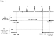
- Fig. 1 is a diagram illustrating an example of control of time-series data and measurement time of R wave extracted from electrocardiographic waveform of a user.
- Fig. 1(a) illustrates R wave detection control in a measurement control apparatus according to an example of the related art.
- the measurement control apparatus according to the example of the related art intermittently measures a heart rate of a user on the basis of a predefined time in which an electrocardiographic waveform is acquired and a heart rate is detected (normal operation: ON) and a time in which the measurement control apparatus is put in a standby state (standby operation: OFF).
- the measurement is continued until a set end time of the normal operation.
- the measurement control apparatus 1 acquires the R-R interval at a timing at which the R wave is detected as illustrated in Fig. 1(b) , and determines whether or not the R wave will have appeared by the set end time on the basis of the acquired R-R interval, in addition to the intermittent operation.
- the measurement control apparatus 1 continues the measurement when the measurement control apparatus 1 determines that the R wave will have appeared by the set end time, but terminates the normal operation of measuring the heart rate at a time point at which the R wave that appears last has been measured, when the measurement control apparatus 1 determines that the R wave will not have appeared by the set end time.
- the measurement control apparatus 1 terminates the measurement before the end time is reached as illustrated in Fig. 1(b) , it is possible to reduce a useless operation time in a period of time in which no R wave is detected, and it is possible to achieve power saving of a measurement system.
- the heart rate is calculated using the R-R interval.
- the measurement control apparatus 1 includes a sensor data acquisition unit 10, an extraction unit 11, an interval acquisition unit 12, a determination unit 13, a termination processing unit 14, a storage unit 15, and a transmission and reception unit 16.
- the sensor data acquisition unit 10 acquires biological information of the user from the sensor 2. More specifically, the sensor data acquisition unit 10, for example, acquires the electrocardiographic signal of the user from the sensor 2 configured of the electrocardiograph in a preset period of time from a start time to a end time of the normal operation. The sensor data acquisition unit 10 amplifies the electrocardiographic signal of the user acquired from the sensor 2, and converts the amplified electrocardiographic signal that is an analog signal into a digital signal at a predetermined sampling frequency. Further, the sensor data acquisition unit 10 removes noise from the acquired electrocardiographic waveform as necessary. The electrocardiographic waveform of the user acquired by the sensor data acquisition unit 10 is stored in the storage unit 15.
- the extraction unit 11 extracts a feature quantity having periodicity from time-series data of biological information of the user acquired by the sensor data acquisition unit 10. Specifically, the extraction unit 11 extracts an R wave, which is one of main components, from the electrocardiographic waveform acquired by the sensor data acquisition unit 10.
- the interval acquisition unit 12 acquires a period of the feature quantity of the biological information extracted by the extraction unit 11. Specifically, the interval acquisition unit 12 acquires the R-R interval, which is a period of the R wave extracted from the electrocardiographic waveform by the extraction unit 11. The interval acquisition unit 12 may perform calculation using the latest instantaneous heart rate or average heart rate (see PTL 2) when acquiring the R-R interval.
- the acquired R-R interval is stored in the storage unit 15. In the present embodiment, the R-R interval acquired by the interval acquisition unit 12 is used as the heart rate of the user.
- the determination unit 13 determines whether or not the feature quantity will have appeared by the set end time of the normal operation on the basis of the period of the feature quantity acquired by the interval acquisition unit 12. When the determination unit 13 determines that the feature quantity of the biological information will not have appeared by the set end time, the determination unit 13 outputs a termination signal indicating that the normal operation will be terminated before the end time of the normal operation. Specifically, the determination unit 13 determines whether or not the R wave will have appeared in the time-series data of the R wave by the set end time on the basis of the R-R interval, and outputs a termination signal when the R wave will not have appeared.
- the termination processing unit 14 terminates an operation of the sensor data acquisition unit 10 when the determination unit 13 determines that the feature quantity will not have appeared by the set end time. More specifically, the termination processing unit 14 stops the acquisition of the biological information by the sensor data acquisition unit 10 when there is an input of a termination signal from the determination unit 13. More specifically, the termination processing unit 14 can stop power supply from a power supply apparatus 110 to be described below to the sensor data acquisition unit 10.
- the termination processing unit 14 stops the acquisition of the biological information by the sensor data acquisition unit 10, a transition from the normal operation for measuring the heart rate of the user to the standby operation or a sleep operation occurs.
- the termination processing unit 14 can perform termination processing such as a standby state in which power is supplied to a memory or a pause state in which memory content or a computer state is evacuated to a hard disk and power is completely turned off according to a hardware configuration of the measurement control apparatus 1, required power consumption, or the like.
- the storage unit 15 stores the time-series data of the biological information of the user acquired by the sensor data acquisition unit 10. Further, the storage unit 15 stores the R wave extracted by the extraction unit 11. Further, the storage unit 15 stores the R-R interval acquired by the interval acquisition unit 12. Further, the storage unit 15 stores the preset end time of the normal operation.
- the transmission and reception unit 16 transmits the heart rate of the user calculated on the basis of the R-R interval acquired by the interval acquisition unit 12 to an external server, terminal apparatus, or the like.
- the transmission and reception unit 16 can transmit, for example, an instantaneous heart rate or an average heart rate to the outside. Further, sensor data can be acquired from the sensor 2 via the transmission and reception unit 16.
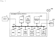
- the measurement control apparatus 1 can be realized by, for example, a computer including a micro control unit (MCU) 102, a main storage apparatus 103, a communication interface 104, an analog front end (AFE) 105, an analog to digital converter (ADC) 106, an auxiliary storage apparatus 107, an input and output apparatus 108, a clock 109, and the power supply apparatus 110 connected via a bus 101, and a program for controlling these hardware resources.
- the sensor 2 provided outside and a display apparatus 111 provided inside the measurement control apparatus 1 are connected via the bus 101.
- a program for enabling the MCU 102 to perform various controls or calculations is stored in the main storage apparatus 103 in advance.
- Each function of the measurement control apparatus 1 including the extraction unit 11, the interval acquisition unit 12, the determination unit 13, and the termination processing unit 14 illustrated in Fig. 2 is realized by the MCU 102 and the main storage apparatus 103.
- the communication interface 104 is an interface circuit for communicating with various external electronic devices via a communication network NW.
- a calculation interface and an antenna corresponding to a wireless data communication standard such as LTE, 3G, wireless LAN, or Bluetooth (registered trademark) Low Energy (BLE) can be used as the communication interface 104.
- the communication interface 104 can be realized by a communication interface circuit corresponding to a wired communication standard such as Ethernet (registered trademark).
- the transmission and reception unit 16 described with reference to Fig. 2 is realized by the communication interface 104.
- the AFE 105 includes an amplification circuit that amplifies and outputs a weak electrocardiographic signal of the user acquired from the sensor 2.
- the ADC 106 includes an analog-to-digital conversion circuit that converts an analog signal amplified by the AFE 105 into a digital signal at a predetermined sampling frequency.
- the ADC 106 outputs time-series data of the electrocardiographic signal converted into the digital signal.
- the sensor data acquisition unit 10 described with reference to Fig. 2 is realized by the AFE 105 and the ADC 106.
- the auxiliary storage apparatus 107 is configured of a readable and writable storage medium, and a drive apparatus for reading or writing various pieces of information such as programs or data to the storage medium.
- a non-volatile memory such as a flash memory can be used as the storage medium.
- the auxiliary storage apparatus 107 may be realized by, for example, a volatile memory such as a DRAM.
- the auxiliary storage apparatus 107 has a storage area in which the biological information measured by the sensor 2 is stored, and a program storage area in which a program enabling the measurement control apparatus 1 to perform control of the measurement of the biological information is stored.
- the storage unit 15 described with reference to Fig. 2 is realized by the auxiliary storage apparatus 107. Further, for example, the auxiliary storage apparatus 107 may have a backup area for backing up, for example, the data or program described above.
- the input and output apparatus 108 is configured of an I/O terminal for inputting a signal from an external device such as the sensor 2 or the display apparatus 111 and outputting a signal to the external device.
- the clock 109 is configured of, for example, a built-in clock built in the computer and measures a time.
- the time information obtained by the clock 109 is referred to when the sensor data is sampled or when the MCU 102 (the extraction unit 11, the interval acquisition unit 12, the determination unit 13, and the termination processing unit 14) uses the time information.
- the power supply apparatus 110 is realized by a power supply circuit that supplies power to the entire measurement control apparatus 1 including the MCU 102, the main storage apparatus 103, the communication interface 104, the AFE 105, the ADC 106, the auxiliary storage apparatus 107, the input and output apparatus 108, and the clock 109.
- the sensor 2 is attached to the user in advance, the electrocardiographic signal of the user is measured, and the following processing is executed.
- the sensor 2 is configured of the electrocardiograph.
- a period of time of the normal operation in which measurement of the heart rate is executed through the intermittent operation, that is, the set end time of the normal operation is stored in the storage unit 15 in advance. Further, information on a time in which the set standby operation is executed is stored in the storage unit 15.
- the MCU 102 is activated (ON) (step S1).
- the AFE 105 is then activated (ON) (step S2).
- the analog signal acquired by the AFE 105 is stabilized and then power is supplied to the ADC 106 so that the ADC 106 is activated (ON) (step S3).
- the sensor data acquisition unit 10 acquires the electrocardiographic signal of the user from the sensor 2 (step S4).
- the sensor data acquisition unit 10 amplifies the acquired electrocardiographic signal of the user (step S5).
- the AFE 105 amplifies and outputs the signal.
- the sensor data acquisition unit 10 converts the amplified analog electrocardiographic signal into a digital signal at a set sampling frequency (step S6).
- the ADC 106 converts the electrocardiographic signal as an analog signal into a digital signal and outputs the digital signal. Thereafter, output time-series data of an electrocardiographic potential of the user is stored in the storage unit 15 (step S7).
- the extraction unit 11 then extracts the R wave from the time-series data of the electrocardiographic potential of the user stored in the storage unit 15 (step S8).
- the extraction unit 11 extracts the R wave appearing at regular intervals included in the time-series data of the electrocardiographic potential in step S8 and stores the R wave in the storage unit 15. More specifically, the extraction unit 11 can use a value considering a clearance before and after a peak derived from the R wave from a time difference value of the electrocardiographic potential as an index value for R wave extraction (see PTL 3).
- the extraction unit 11 can set a threshold value for time-series data of this index value according to an amplitude of the R wave, and can detect the R wave using the fact that a data value exceeds this threshold value (see PTL 4).
- the interval acquisition unit 12 acquires the R-R interval indicating a period in which the R wave appears, from the plurality of R waves included in the electrocardiographic waveform of the user extracted in step S8 (step S9: YES). Specifically, when at least two R waves are extracted in step S8, the interval acquisition unit 12 can calculate the instantaneous heart rate from the period of the R waves appearing at time intervals adjacent to each other (see PTL 4).
- the average heart rate can be calculated using a median, arithmetic mean, or moving average of the heart rate measured in the normal operation.
- HR ave i r ⁇ HR i + 1 ⁇ r ⁇ HR ave i ⁇ 1
- the determination unit 13 determines whether or not the R wave will have appeared by the set end time on the basis of the R-R interval acquired in step S9, and outputs a signal indicating that the measurement is to be terminated when the R wave will not have appeared (step S10: YES), and the process proceeds to step S12.
- the determination unit 13 uses Formula (2) below in determining whether or not to terminate the measurement.
- t indicates a measurement time in the normal operation
- X indicates the instantaneous heart rate or the average heart rate calculated from the latest R-R interval.
- 60/Y(X) indicates a predicted time [sec] by which the next R wave appears, which is estimated from X.
- the determination unit 13 When a left side of Formula (2) above exceeds the set end time t measure , the determination unit 13 outputs the termination signal because no more R wave appears in the normal operation of the present intermittent operation.
- the determination unit 13 can obtain Y(X) included in Formula (2) above by using any of Formulas (3) to (8) below.
- Y(X) is calculated using Formula (3) below in consideration of the m missing R waves (m is an integer equal to or greater than 0).
- Y X m + 1 X
- Y(X) can be calculated using Formula (4) below in consideration of a heart rate variation amount ⁇ X.
- the heart rate variation amount ⁇ X is experimentally obtained in advance and stored in the storage unit 15.
- Y X m + 1 X + ⁇ X
- Y(X) can be calculated using Formula (5) in additional consideration of an upper limit X max of the heart rate that may be generated.
- Y(X) can be calculated using Formula (6) below in additional consideration of the upper limit X max of the heart rate that may be generated.
- the determination unit 13 can calculate Y(X) using Formula (7) in additional consideration of the upper limit X max of the heart rate that may be generated in the example using Formula (3) above.
- r is a constant that takes 0 ⁇ r ⁇ 1.
- Y X ⁇ n + 1 X X ⁇ X max n + 1 n + r X X max n + r ⁇ X ⁇ X max n + r n ⁇ 1 + r X X max n + r ⁇ X ⁇ X max n ⁇ 1 + r ⁇ 1 + r X X max 2 + r ⁇ X ⁇ X max 1 + r X max X max 1 + r ⁇ X
- the determination unit 13 can calculate Y(X) using Formula (8) below in consideration of the heart rate variation amount ⁇ X used in Formula (4) in the example of Formula (7) above.
- Y X ⁇ n + 1 X + ⁇ X X + ⁇ X ⁇ X max n + 1 n + r X + ⁇ X X max n + r ⁇ X + ⁇ X ⁇ X max n + r n ⁇ 1 + r X + ⁇ X X max n + r ⁇ X + ⁇ X ⁇ X max n ⁇ 1 + r ⁇ 1 + r X + ⁇ X X max 2 + r ⁇ X + ⁇ X ⁇ X max 1 + r X max X max 1 + r ⁇ X + ⁇ X
- step S9 NO
- step S11 YES
- the termination processing unit 14 stops supply of power from the power supply apparatus 110 to the ADC 106 (step S12). Thereafter, the termination processing unit 14 stops supply of power from the power supply apparatus 110 to the AFE 105 (step S13) .
- the MCU 102 reads the heart rate of the user stored in the storage unit 15 to generate a packet, and transmits data from the transmission and reception unit 16 to an external terminal via the communication network NW (step S14). Thereafter, the termination processing unit 14 puts the MCU 102 in the standby state (OFF) (step S15).
- the measurement control apparatus 1 can execute the normal operation again by repeating steps S1 to S15 again after a set standby period of time.
- a horizontal axis represents time [hour: minute: second]
- a vertical axis represents electrocardiographic potential [ ⁇ V].
- the operation timing (ON/ OFF) of the measurement control apparatus 1 overlaps the electrocardiographic waveform.
- Formula (2) above is used when the determination unit 13 determines the termination.
- X is the median value of the instantaneous heart rate in the normal operation.
- the determination unit 13 when the determination unit 13 outputs the termination signal and the measurement is terminated, the measurement ends at a time a' before the set end time a. Therefore, it is possible to eliminate a useless measurement time in which no R wave is detected. Specifically, when the determination unit 13 determines the termination, an operation time is saved by about 26% as compared with the example of the related art (a broken line in Fig. 5 ), and power saving can be achieved.
- the determination unit 13 determines whether or not the R wave will have appeared by the set end time on the basis of the R-R interval of the R wave of the user, it is possible to perform measurement of the biological information such as the heart rate of the user with more power saving.
- the electrocardiographic waveform of the user is acquired by the sensor 2 including the electrocardiograph, the R-R interval is acquired from the electrocardiographic waveform, and the measurement of the heart rate and the determination as to the termination are performed has been described.
- the sensor 2 is not limited to the described specific example as long as information indicates, for example, a state of the user measured on the basis of the feature quantity of the biological information with periodicity, for example, when the number of beats of the user such as a pulse is measured by a pulse rate monitor.
- measurement targets that are controlled by the measurement control apparatus 1 are not limited to the measurement of the R-R interval of the electrocardiographic waveform and the heart rate, and other feature quantities included in the electrocardiographic waveform may be extracted.
- the biological information of the user may be measured by observing P wave, Q wave, S wave, T wave, and the like.
Landscapes
- Health & Medical Sciences (AREA)
- Life Sciences & Earth Sciences (AREA)
- Cardiology (AREA)
- Engineering & Computer Science (AREA)
- Molecular Biology (AREA)
- General Health & Medical Sciences (AREA)
- Veterinary Medicine (AREA)
- Biophysics (AREA)
- Pathology (AREA)
- Biomedical Technology (AREA)
- Heart & Thoracic Surgery (AREA)
- Medical Informatics (AREA)
- Public Health (AREA)
- Surgery (AREA)
- Animal Behavior & Ethology (AREA)
- Physics & Mathematics (AREA)
- Signal Processing (AREA)
- Physiology (AREA)
- Power Engineering (AREA)
- Artificial Intelligence (AREA)
- Computer Vision & Pattern Recognition (AREA)
- Psychiatry (AREA)
- Measurement And Recording Of Electrical Phenomena And Electrical Characteristics Of The Living Body (AREA)
- Measuring Pulse, Heart Rate, Blood Pressure Or Blood Flow (AREA)
- Analysing Materials By The Use Of Radiation (AREA)
Abstract
Description
- The present invention relates to a measurement control apparatus and a measurement control method, and particularly, to a technology for controlling a measurement operation of biological information.
- In recent years, wearable devices have been attracting attention as representative communication terminals in an IoT era. An example of the wearable devices includes a consumer device such as smart watch, or a healthcare terminal that is attached to clothing to monitor biological information such as the number of steps, an activity amount, or a heart rate of a user. Further, wearable devices for business use that monitor work or an environment of employees have also been developed, and some wearable devices have already been put into practical use (see NPL 1).
- In particular, for wearable devices for healthcare use, growing health consciousness according to global aging or a demand for point of care has also been attracting attention. The wearable devices for healthcare are able to review or improve lifestyle habits and prevent diseases such as lifestyle-related diseases by utilizing monitoring information through measurement or monitoring of biological information in daily life. Therefore, the wearable devices for healthcare are expected to maintain and improve people's living standards.
- As an example,
PTL 1 discloses an application in which a user wears clothing to which a sensor terminal is attached so that a biological state such as a stress state of a user estimated from an electrocardiographic waveform of the user, a heart rate of the user, and an R wave interval is acquired. - Generally, in such a wearable device of the related art, a battery occupies a large proportion of a mass and a volume of the entire device. It is necessary to reduce a battery capacity in order to reduce a weight and size of the device. Therefore, power saving of the entire device is required. Further, in the case of a device in which monitoring for a long time in daily life such as heart rate measurement is assumed, reduction of power consumption at the time of an operation of the device can be said to be an important technical issue.
- In response to such a problem, a heart rate measurement apparatus described in
PTL 1 intermittently executes transmission of data to an external device while temporarily accumulating measurement data so that power saving is achieved. However, measurement of the electrocardiographic signal itself is always executed, and it can be said that there is still room for decreasing power consumption of an intermittent operation of heart rate measurement itself, or the like. -
- [PTL 1]
WO 2016/024495 - [PTL 2]
Japanese Patent Application Publication No. 2018-011819 - [PTL 3] Republished International Patent Publication No.
WO 2017/150156 - [PTL 4]
Japanese Patent Application Publication No. 2015-156936 - [NPL 1] "2018 White Paper on Information and Communications" Ministry of Internal Affairs and Communications: pp. 14-15
- The present invention has been made to solve the above-described problems, and an object of the present invention is to provide a measurement control technology capable of performing measurement of biological information with more power saving.
- In order to solve the above-described problem, a measurement control apparatus according to the present invention includes a sensor data acquisition unit configured to acquire biological information of a user measured by a sensor; an extraction unit configured to extract a feature quantity with periodicity from the biological information acquired by the sensor data acquisition unit; an interval acquisition unit configured to acquire a period of the extracted feature quantity; a determination unit configured to determine whether or not the feature quantity will have appeared by a set end time on the basis of the acquired period of the feature quantity; and a termination processing unit configured to terminate an operation of the sensor data acquisition unit when the determination unit determines that the feature quantity will not have appeared by the set end time.
- Further, in the measurement control apparatus according to the present invention, the termination processing unit may stop the acquisition of the biological information by the sensor data acquisition unit.
- Further, in the measurement control apparatus according to the present invention, the termination processing unit may stop supply of power to the sensor data acquisition unit.
- Further, in the measurement control apparatus according to the present invention, the sensor data acquisition unit may amplify an analog signal indicating the biological information, and discretize the amplified analog signal in a preset sampling period to convert the analog signal into a digital signal.
- Further, in the measurement control apparatus according to the present invention, the sensor data acquisition unit may acquire an electrocardiographic signal of the user from the sensor including an electrocardiograph.
- Further, in the measurement control apparatus according to the present invention, the extraction unit may extract an R wave included in the electrocardiographic signal as the feature quantity, the interval acquisition unit may acquire an R-R interval indicating an interval of the R wave as the period, and the determination unit may determine whether or not the R wave will have appeared at the set end time on the basis of the R-R interval.
- Further, in the measurement control apparatus according to the present invention, the determination unit may determine whether or not the R wave will have appeared by the set end time through comparison with the set end time on the basis of any time at which the sensor data acquisition unit acquires the electrocardiographic signal and a predicted time at which the next R wave will appear, the predicted time being estimated on the basis of an instantaneous heart rate or an average heart rate calculated from a latest R-R interval acquired by the interval acquisition unit.
- Further, in order to solve the above-described problem, a measurement control method according to the present invention includes a first step of acquiring biological information of a user measured by a sensor; a second step of extracting a feature quantity with periodicity from the biological information acquired in the first step; a third step of acquiring the period of the extracted feature quantity; a fourth step of determining whether or not the feature quantity will have appeared by a set end time on the basis of the acquired period of the feature quantity; and a fifth step of terminating the acquisition of the biological information in the first step when it is determined in the fourth step that the feature quantity will not have appeared by the set end time.
- According to the present invention, since it is determined whether or not the feature quantity will have appeared by the set end time on the basis of the acquired period of the feature quantity of the biological information of the user, and the acquisition of the biological information is ended when the feature quantity will not have appeared, it is possible to perform the measurement of the biological information with more power saving.
-
- [
Fig. 1 ]
Fig. 1 is a diagram illustrating an overview of a measurement control apparatus according to an embodiment of the present invention. - [
Fig. 2 ]
Fig. 2 is a block diagram illustrating a functional configuration of the measurement control apparatus according to the embodiment of the present invention. - [
Fig. 3 ]
Fig. 3 is a block diagram illustrating a hardware configuration of the measurement control apparatus according to the embodiment of the present invention. - [
Fig. 4 ]
Fig. 4 is a flowchart illustrating an operation of the measurement control apparatus according to the embodiment of the present invention. - [
Fig. 5 ]
Fig. 5 is a diagram illustrating effects of the measurement control apparatus according to the embodiment of the present invention. - Hereinafter, a preferred embodiment of the present invention will be described in detail with reference to
Figs. 1 to 5 . Further, an example in which an electrocardiographic signal of a user is used as biological information that is measured by ameasurement control apparatus 1, an R wave is extracted as a feature quantity of the electrocardiographic signal, and a heart rate of the user is measured on the basis of the number of R waves of an electrocardiographic waveform per minute will be described in the present embodiment. - The
measurement control apparatus 1 according to the present embodiment repeats a normal operation and a standby operation in a preset period of time to perform control of an intermittent operation in which the heart rate of the user is measured. In the normal operation, the heart rate of the user is measured, and in standby operation, the heart rate of the user is not measured.
Asensor 2 includes, for example, an electrocardiograph, and is attached to the user to measure the electrocardiographic signal of the user. -
Fig. 1 is a diagram illustrating an example of control of time-series data and measurement time of R wave extracted from electrocardiographic waveform of a user.Fig. 1(a) illustrates R wave detection control in a measurement control apparatus according to an example of the related art. The measurement control apparatus according to the example of the related art intermittently measures a heart rate of a user on the basis of a predefined time in which an electrocardiographic waveform is acquired and a heart rate is detected (normal operation: ON) and a time in which the measurement control apparatus is put in a standby state (standby operation: OFF). Thus, in the measurement control apparatus according to the example of the related art, the measurement is continued until a set end time of the normal operation. - On the other hand, the
measurement control apparatus 1 according to the present embodiment acquires the R-R interval at a timing at which the R wave is detected as illustrated inFig. 1(b) , and determines whether or not the R wave will have appeared by the set end time on the basis of the acquired R-R interval, in addition to the intermittent operation. Themeasurement control apparatus 1 continues the measurement when themeasurement control apparatus 1 determines that the R wave will have appeared by the set end time, but terminates the normal operation of measuring the heart rate at a time point at which the R wave that appears last has been measured, when themeasurement control apparatus 1 determines that the R wave will not have appeared by the set end time. When themeasurement control apparatus 1 terminates the measurement before the end time is reached as illustrated inFig. 1(b) , it is possible to reduce a useless operation time in a period of time in which no R wave is detected, and it is possible to achieve power saving of a measurement system. The heart rate is calculated using the R-R interval. - Next, a functional configuration of the
measurement control apparatus 1 according to the present embodiment will be described with reference toFig. 2 . As illustrated inFig. 2 , themeasurement control apparatus 1 includes a sensordata acquisition unit 10, anextraction unit 11, aninterval acquisition unit 12, adetermination unit 13, atermination processing unit 14, astorage unit 15, and a transmission andreception unit 16. - The sensor
data acquisition unit 10 acquires biological information of the user from thesensor 2. More specifically, the sensordata acquisition unit 10, for example, acquires the electrocardiographic signal of the user from thesensor 2 configured of the electrocardiograph in a preset period of time from a start time to a end time of the normal operation. The sensordata acquisition unit 10 amplifies the electrocardiographic signal of the user acquired from thesensor 2, and converts the amplified electrocardiographic signal that is an analog signal into a digital signal at a predetermined sampling frequency. Further, the sensordata acquisition unit 10 removes noise from the acquired electrocardiographic waveform as necessary. The electrocardiographic waveform of the user acquired by the sensordata acquisition unit 10 is stored in thestorage unit 15. - The
extraction unit 11 extracts a feature quantity having periodicity from time-series data of biological information of the user acquired by the sensordata acquisition unit 10. Specifically, theextraction unit 11 extracts an R wave, which is one of main components, from the electrocardiographic waveform acquired by the sensordata acquisition unit 10. - The
interval acquisition unit 12 acquires a period of the feature quantity of the biological information extracted by theextraction unit 11. Specifically, theinterval acquisition unit 12 acquires the R-R interval, which is a period of the R wave extracted from the electrocardiographic waveform by theextraction unit 11. Theinterval acquisition unit 12 may perform calculation using the latest instantaneous heart rate or average heart rate (see PTL 2) when acquiring the R-R interval. The acquired R-R interval is stored in thestorage unit 15. In the present embodiment, the R-R interval acquired by theinterval acquisition unit 12 is used as the heart rate of the user. - The
determination unit 13 determines whether or not the feature quantity will have appeared by the set end time of the normal operation on the basis of the period of the feature quantity acquired by theinterval acquisition unit 12. When thedetermination unit 13 determines that the feature quantity of the biological information will not have appeared by the set end time, thedetermination unit 13 outputs a termination signal indicating that the normal operation will be terminated before the end time of the normal operation. Specifically, thedetermination unit 13 determines whether or not the R wave will have appeared in the time-series data of the R wave by the set end time on the basis of the R-R interval, and outputs a termination signal when the R wave will not have appeared. - The
termination processing unit 14 terminates an operation of the sensordata acquisition unit 10 when thedetermination unit 13 determines that the feature quantity will not have appeared by the set end time. More specifically, thetermination processing unit 14 stops the acquisition of the biological information by the sensordata acquisition unit 10 when there is an input of a termination signal from thedetermination unit 13. More specifically, thetermination processing unit 14 can stop power supply from apower supply apparatus 110 to be described below to the sensordata acquisition unit 10. - When the
termination processing unit 14 stops the acquisition of the biological information by the sensordata acquisition unit 10, a transition from the normal operation for measuring the heart rate of the user to the standby operation or a sleep operation occurs. Thetermination processing unit 14 can perform termination processing such as a standby state in which power is supplied to a memory or a pause state in which memory content or a computer state is evacuated to a hard disk and power is completely turned off according to a hardware configuration of themeasurement control apparatus 1, required power consumption, or the like. - The
storage unit 15 stores the time-series data of the biological information of the user acquired by the sensordata acquisition unit 10. Further, thestorage unit 15 stores the R wave extracted by theextraction unit 11. Further, thestorage unit 15 stores the R-R interval acquired by theinterval acquisition unit 12. Further, thestorage unit 15 stores the preset end time of the normal operation. - The transmission and
reception unit 16 transmits the heart rate of the user calculated on the basis of the R-R interval acquired by theinterval acquisition unit 12 to an external server, terminal apparatus, or the like. The transmission andreception unit 16 can transmit, for example, an instantaneous heart rate or an average heart rate to the outside. Further, sensor data can be acquired from thesensor 2 via the transmission andreception unit 16. - Next, a hardware configuration of the
measurement control apparatus 1 having the above-described functional configuration will be described with reference to a block diagram ofFig. 3 . - As illustrated in
Fig. 3 , themeasurement control apparatus 1 can be realized by, for example, a computer including a micro control unit (MCU) 102, amain storage apparatus 103, acommunication interface 104, an analog front end (AFE) 105, an analog to digital converter (ADC) 106, anauxiliary storage apparatus 107, an input andoutput apparatus 108, aclock 109, and thepower supply apparatus 110 connected via abus 101, and a program for controlling these hardware resources. In themeasurement control apparatus 1, thesensor 2 provided outside and adisplay apparatus 111 provided inside themeasurement control apparatus 1 are connected via thebus 101. - A program for enabling the
MCU 102 to perform various controls or calculations is stored in themain storage apparatus 103 in advance. Each function of themeasurement control apparatus 1 including theextraction unit 11, theinterval acquisition unit 12, thedetermination unit 13, and thetermination processing unit 14 illustrated inFig. 2 is realized by theMCU 102 and themain storage apparatus 103. - The
communication interface 104 is an interface circuit for communicating with various external electronic devices via a communication network NW. - For example, a calculation interface and an antenna corresponding to a wireless data communication standard such as LTE, 3G, wireless LAN, or Bluetooth (registered trademark) Low Energy (BLE) can be used as the
communication interface 104. Further, thecommunication interface 104 can be realized by a communication interface circuit corresponding to a wired communication standard such as Ethernet (registered trademark). The transmission andreception unit 16 described with reference toFig. 2 is realized by thecommunication interface 104. - The
AFE 105 includes an amplification circuit that amplifies and outputs a weak electrocardiographic signal of the user acquired from thesensor 2.
TheADC 106 includes an analog-to-digital conversion circuit that converts an analog signal amplified by theAFE 105 into a digital signal at a predetermined sampling frequency. TheADC 106 outputs time-series data of the electrocardiographic signal converted into the digital signal. The sensordata acquisition unit 10 described with reference toFig. 2 is realized by theAFE 105 and theADC 106. - The
auxiliary storage apparatus 107 is configured of a readable and writable storage medium, and a drive apparatus for reading or writing various pieces of information such as programs or data to the storage medium. In theauxiliary storage apparatus 107, a non-volatile memory such as a flash memory can be used as the storage medium. Theauxiliary storage apparatus 107 may be realized by, for example, a volatile memory such as a DRAM. - The
auxiliary storage apparatus 107 has a storage area in which the biological information measured by thesensor 2 is stored, and a program storage area in which a program enabling themeasurement control apparatus 1 to perform control of the measurement of the biological information is stored. Thestorage unit 15 described with reference toFig. 2 is realized by theauxiliary storage apparatus 107. Further, for example, theauxiliary storage apparatus 107 may have a backup area for backing up, for example, the data or program described above. - The input and
output apparatus 108 is configured of an I/O terminal for inputting a signal from an external device such as thesensor 2 or thedisplay apparatus 111 and outputting a signal to the external device. - The
clock 109 is configured of, for example, a built-in clock built in the computer and measures a time. The time information obtained by theclock 109 is referred to when the sensor data is sampled or when the MCU 102 (theextraction unit 11, theinterval acquisition unit 12, thedetermination unit 13, and the termination processing unit 14) uses the time information. - The
power supply apparatus 110 is realized by a power supply circuit that supplies power to the entiremeasurement control apparatus 1 including theMCU 102, themain storage apparatus 103, thecommunication interface 104, theAFE 105, theADC 106, theauxiliary storage apparatus 107, the input andoutput apparatus 108, and theclock 109. - Next, an operation of the
measurement control apparatus 1 having the above-described configuration will be described with reference to a flowchart ofFig. 4 . Thesensor 2 is attached to the user in advance, the electrocardiographic signal of the user is measured, and the following processing is executed. For example, thesensor 2 is configured of the electrocardiograph. Further, a period of time of the normal operation in which measurement of the heart rate is executed through the intermittent operation, that is, the set end time of the normal operation is stored in thestorage unit 15 in advance. Further, information on a time in which the set standby operation is executed is stored in thestorage unit 15. - First, the
MCU 102 is activated (ON) (step S1). TheAFE 105 is then activated (ON) (step S2). Thereafter, the analog signal acquired by theAFE 105 is stabilized and then power is supplied to theADC 106 so that theADC 106 is activated (ON) (step S3). Thereafter, the sensordata acquisition unit 10 acquires the electrocardiographic signal of the user from the sensor 2 (step S4). Then, the sensordata acquisition unit 10 amplifies the acquired electrocardiographic signal of the user (step S5). Specifically, theAFE 105 amplifies and outputs the signal. - Next, the sensor
data acquisition unit 10 converts the amplified analog electrocardiographic signal into a digital signal at a set sampling frequency (step S6). Specifically, theADC 106 converts the electrocardiographic signal as an analog signal into a digital signal and outputs the digital signal. Thereafter, output time-series data of an electrocardiographic potential of the user is stored in the storage unit 15 (step S7). - The
extraction unit 11 then extracts the R wave from the time-series data of the electrocardiographic potential of the user stored in the storage unit 15 (step S8). Theextraction unit 11 extracts the R wave appearing at regular intervals included in the time-series data of the electrocardiographic potential in step S8 and stores the R wave in thestorage unit 15. More specifically, theextraction unit 11 can use a value considering a clearance before and after a peak derived from the R wave from a time difference value of the electrocardiographic potential as an index value for R wave extraction (see PTL 3). Theextraction unit 11 can set a threshold value for time-series data of this index value according to an amplitude of the R wave, and can detect the R wave using the fact that a data value exceeds this threshold value (see PTL 4). - Thereafter, the
interval acquisition unit 12 acquires the R-R interval indicating a period in which the R wave appears, from the plurality of R waves included in the electrocardiographic waveform of the user extracted in step S8 (step S9: YES). Specifically, when at least two R waves are extracted in step S8, theinterval acquisition unit 12 can calculate the instantaneous heart rate from the period of the R waves appearing at time intervals adjacent to each other (see PTL 4). - The average heart rate can be calculated using a median, arithmetic mean, or moving average of the heart rate measured in the normal operation. Alternatively, an average value HRave(i) may be calculated by Formula (1) below using an instantaneous heart rate HR(i) obtained from data of an i-th R-R interval, an averaged value HRave(i-1) of instantaneous heart rates up to an (i-1) th instantaneous heart rate, and a predetermined averaging coefficient r (for example, r = 0,1) as described in
PTL 2.
- The
determination unit 13 then determines whether or not the R wave will have appeared by the set end time on the basis of the R-R interval acquired in step S9, and outputs a signal indicating that the measurement is to be terminated when the R wave will not have appeared (step S10: YES), and the process proceeds to step S12. - More specifically, the
determination unit 13 uses Formula (2) below in determining whether or not to terminate the measurement. -

- In Formula (2) above, t indicates a measurement time in the normal operation, and X indicates the instantaneous heart rate or the average heart rate calculated from the latest R-R interval. Further, 60/Y(X) indicates a predicted time [sec] by which the next R wave appears, which is estimated from X.
- When a left side of Formula (2) above exceeds the set end time tmeasure, the
determination unit 13 outputs the termination signal because no more R wave appears in the normal operation of the present intermittent operation. - The
determination unit 13 can obtain Y(X) included in Formula (2) above by using any of Formulas (3) to (8) below. - For example, a case in which a plurality of R waves are missing due to, for example, a small amplitude of the R wave, and X has a value smaller than an actual value is considered. For example, Y(X) is calculated using Formula (3) below in consideration of the m missing R waves (m is an integer equal to or greater than 0).

- In addition to the consideration in Formula (3) above, it is considered that the heart rate varies sequentially. In this case, for example, Y(X) can be calculated using Formula (4) below in consideration of a heart rate variation amount ΔX. The heart rate variation amount ΔX is experimentally obtained in advance and stored in the
storage unit 15.
- Alternatively, when m = 0 in the example of Formula (3) above, that is, when missing of the R wave is not considered, Y(X) can be calculated using Formula (5) in additional consideration of an upper limit Xmax of the heart rate that may be generated.
-

- Further, as another example, in Formula (4) above in which the heart rate variation amount ΔX is considered, when m = 0, that is, when the missing of the R wave is not considered, Y(X) can be calculated using Formula (6) below in additional consideration of the upper limit Xmax of the heart rate that may be generated.
-

- Alternatively, when missing of n or more (n is a natural number) R wave is considered, the
determination unit 13 can calculate Y(X) using Formula (7) in additional consideration of the upper limit Xmax of the heart rate that may be generated in the example using Formula (3) above. r is a constant that takes 0 ≤ r < 1. -

- Alternatively, the
determination unit 13 can calculate Y(X) using Formula (8) below in consideration of the heart rate variation amount ΔX used in Formula (4) in the example of Formula (7) above. -

- Referring back to
Fig. 4 , when theinterval acquisition unit 12 has not acquired the R-R interval in step S9 (step S9: NO) and the set end time is reached (step S11: YES), thetermination processing unit 14 proceeds to a process of terminating the measurement (step S12). - When the termination signal is output (step S10: YES) or the set end time is reached (step S11: YES), the
termination processing unit 14 stops supply of power from thepower supply apparatus 110 to the ADC 106 (step S12). Thereafter, thetermination processing unit 14 stops supply of power from thepower supply apparatus 110 to the AFE 105 (step S13) . - Thereafter, the
MCU 102 reads the heart rate of the user stored in thestorage unit 15 to generate a packet, and transmits data from the transmission andreception unit 16 to an external terminal via the communication network NW (step S14). Thereafter, thetermination processing unit 14 puts theMCU 102 in the standby state (OFF) (step S15). Through the above processing, the normal operation when themeasurement control apparatus 1 performs the intermittent operation and measures the heart rate of the user ends, and the operation proceeds to the standby operation. Themeasurement control apparatus 1 can execute the normal operation again by repeating steps S1 to S15 again after a set standby period of time. - Next, an ON/OFF operation timing when the
measurement control apparatus 1 according to the present embodiment performs an intermittent operation and determines a termination of the measurement of the electrocardiographic waveform of the user will be described with reference toFig. 5 . InFig. 5 , a horizontal axis represents time [hour: minute: second], and a vertical axis represents electrocardiographic potential [µV]. Further, as illustrated inFig. 5 , the operation timing (ON/ OFF) of themeasurement control apparatus 1 overlaps the electrocardiographic waveform. - Further, in
Fig. 5 , Formula (2) above is used when thedetermination unit 13 determines the termination. Further, Formula (3) above is used with m = 0 in the calculation of Y(X) included in Formula (2). Further, in Formula (3), r = 1/3, ΔX = 15 [bpm] , and tmeasure = 5 [sec] . Further, X is the median value of the instantaneous heart rate in the normal operation. When thedetermination unit 13 does not perform the determination as to the termination in the heart rate measurement, it can be seen that the measurement is continued at a set end time a even though no R wave appears (a broken line inFig. 5 ). - However, in the present embodiment, when the
determination unit 13 outputs the termination signal and the measurement is terminated, the measurement ends at a time a' before the set end time a. Therefore, it is possible to eliminate a useless measurement time in which no R wave is detected. Specifically, when thedetermination unit 13 determines the termination, an operation time is saved by about 26% as compared with the example of the related art (a broken line inFig. 5 ), and power saving can be achieved. - As described above, according to the present embodiment, since the
determination unit 13 determines whether or not the R wave will have appeared by the set end time on the basis of the R-R interval of the R wave of the user, it is possible to perform measurement of the biological information such as the heart rate of the user with more power saving. - In the described embodiment, a case in which the electrocardiographic waveform of the user is acquired by the
sensor 2 including the electrocardiograph, the R-R interval is acquired from the electrocardiographic waveform, and the measurement of the heart rate and the determination as to the termination are performed has been described. However, thesensor 2 is not limited to the described specific example as long as information indicates, for example, a state of the user measured on the basis of the feature quantity of the biological information with periodicity, for example, when the number of beats of the user such as a pulse is measured by a pulse rate monitor. - Further, measurement targets that are controlled by the
measurement control apparatus 1 are not limited to the measurement of the R-R interval of the electrocardiographic waveform and the heart rate, and other feature quantities included in the electrocardiographic waveform may be extracted. For example, the biological information of the user may be measured by observing P wave, Q wave, S wave, T wave, and the like. - Although the embodiments of the measurement control apparatus and the measurement control method of the present invention have been described above, the present invention is not limited to the described embodiments and it is possible to make various modifications that can be assumed by those skilled in the art within the scope of the invention defined in the claims.
-
- 1
- Measurement control apparatus
- 2
- Sensor
- 10
- Sensor data acquisition unit
- 11
- Extraction unit
- 12
- Interval acquisition unit
- 14
- Termination processing unit
- 15
- Storage unit
- 16
- Transmission and reception unit
- 101
- Bus
- 102
- MCU
- 103
- Main storage apparatus
- 104
- Communication interface
- 105
- AFE
- 106
- ADC
- 107
- Auxiliary storage apparatus
- 108
- Input and output apparatus
- 109
- Clock
- 110
- Power supply apparatus
- 111
- Display apparatus
Claims (8)
- A measurement control apparatus comprising:a sensor data acquisition unit configured to acquire biological information of a user measured by a sensor;an extraction unit configured to extract a feature quantity with periodicity from the biological information acquired by the sensor data acquisition unit;an interval acquisition unit configured to acquire a period of the extracted feature quantity;a determination unit configured to determine whether or not the feature quantity will have appeared by a set end time on the basis of the acquired period of the feature quantity; anda termination processing unit configured to terminate an operation of the sensor data acquisition unit when the determination unit determines that the feature quantity will not have appeared by the set end time.
- The measurement control apparatus according to claim 1, wherein the termination processing unit stops the acquisition of the biological information by the sensor data acquisition unit.
- The measurement control apparatus according to claim 1 or 2, wherein the termination processing unit stops supply of power to the sensor data acquisition unit.
- The measurement control apparatus according to any one of claims 1 to 3, wherein the sensor data acquisition unit amplifies an analog signal indicating the biological information, and discretizes the amplified analog signal in a preset sampling period to convert the analog signal into a digital signal.
- The measurement control apparatus according to any one of claims 1 to 4, wherein the sensor data acquisition unit acquires an electrocardiographic signal of the user from the sensor including an electrocardiograph.
- The measurement control apparatus according to claim 5, wherein the extraction unit extracts an R wave included in the electrocardiographic signal as the feature quantity, the interval acquisition unit acquires an R-R interval indicating an interval of the R wave as the period, and the determination unit determines whether or not the R wave will have appeared at the set end time on the basis of the R-R interval.
- The measurement control apparatus according to claim 6, wherein the determination unit determines whether or not the R wave will have appeared by the set end time through comparison with the set end time on the basis of any time at which the sensor data acquisition unit acquires the electrocardiographic signal and a predicted time by which the next R wave appears, the predicted time being estimated on the basis of an instantaneous heart rate or an average heart rate calculated from a latest R-R interval acquired by the interval acquisition unit.
- A measurement control method comprising:a first step of acquiring biological information of a user measured by a sensor;a second step of extracting a feature quantity with periodicity from the biological information acquired in the first step;a third step of acquiring the period of the extracted feature quantity;a fourth step of determining whether or not the feature quantity will have appeared by a set end time on the basis of the acquired period of the feature quantity; anda fifth step of terminating the acquisition of the biological information in the first step when it is determined in the fourth step that the feature quantity will not have appeared by the set end time.
Applications Claiming Priority (2)
| Application Number | Priority Date | Filing Date | Title |
|---|---|---|---|
| JP2019041198A JP7143787B2 (en) | 2019-03-07 | 2019-03-07 | Measurement control device and measurement control method |
| PCT/JP2020/007059 WO2020179499A1 (en) | 2019-03-07 | 2020-02-21 | Measurement control apparatus and measurement control method |
Publications (3)
| Publication Number | Publication Date |
|---|---|
| EP3936833A1 true EP3936833A1 (en) | 2022-01-12 |
| EP3936833A4 EP3936833A4 (en) | 2022-12-07 |
| EP3936833B1 EP3936833B1 (en) | 2024-04-10 |
Family
ID=72337932
Family Applications (1)
| Application Number | Title | Priority Date | Filing Date |
|---|---|---|---|
| EP20767124.9A Active EP3936833B1 (en) | 2019-03-07 | 2020-02-21 | Measurement control apparatus and measurement control method |
Country Status (7)
| Country | Link |
|---|---|
| US (1) | US11672462B2 (en) |
| EP (1) | EP3936833B1 (en) |
| JP (1) | JP7143787B2 (en) |
| AU (1) | AU2020231570B2 (en) |
| CA (1) | CA3131857C (en) |
| ES (1) | ES2976771T3 (en) |
| WO (1) | WO2020179499A1 (en) |
Families Citing this family (1)
| Publication number | Priority date | Publication date | Assignee | Title |
|---|---|---|---|---|
| KR102538647B1 (en) * | 2023-02-22 | 2023-05-31 | 젠다카디언 인코포레이티드 | Apparatus for Determining Rarity of Biometric data and Method thereof |
Family Cites Families (14)
| Publication number | Priority date | Publication date | Assignee | Title |
|---|---|---|---|---|
| US5935069A (en) * | 1997-10-10 | 1999-08-10 | Acuson Corporation | Ultrasound system and method for variable transmission of ultrasonic signals |
| US7460902B2 (en) | 2005-02-02 | 2008-12-02 | The General Electric Company | Monitoring of atrial activation |
| US7437192B2 (en) * | 2005-04-05 | 2008-10-14 | Pacesetter, Inc. | System and method for detecting heart failure and pulmonary edema based on ventricular end-diastolic pressure using an implantable medical device |
| WO2014006891A1 (en) * | 2012-07-06 | 2014-01-09 | パナソニック株式会社 | Biological signal measurement device, and biological signal measurement method |
| JP2014135987A (en) * | 2013-01-16 | 2014-07-28 | Nec Corp | Sensor terminal for acquiring signal including quasi-periodic delimiter pulse, and signal acquisition method |
| JPWO2014141682A1 (en) * | 2013-03-13 | 2017-02-16 | 日本電気株式会社 | Sensor terminal and signal acquisition method |
| JP6281738B2 (en) | 2013-09-17 | 2018-02-21 | カシオ計算機株式会社 | Heart rate measuring device, heart rate measuring method, heart rate measuring program |
| JP6243254B2 (en) | 2014-02-24 | 2017-12-06 | 日本電信電話株式会社 | Heart rate detection method and heart rate detection device |
| US9888857B2 (en) * | 2014-07-16 | 2018-02-13 | Qualcomm Incorporated | Methods and systems for reducing energy consumption of a heart rate monitor |
| US10881315B2 (en) | 2014-08-11 | 2021-01-05 | Nippon Telegraph And Telephone Corporation | Biological signal measurement system, biological information measurement apparatus, and biological information extraction algorithm changing method |
| JP2016047092A (en) | 2014-08-27 | 2016-04-07 | セイコーエプソン株式会社 | Biological information detection device |
| WO2017150156A1 (en) | 2016-02-29 | 2017-09-08 | 日本電信電話株式会社 | Heartbeat detecting method and heartbeat detecting device |
| JP6645926B2 (en) | 2016-07-22 | 2020-02-14 | 日本電信電話株式会社 | Biological signal processing method and apparatus |
| WO2018084157A1 (en) | 2016-11-07 | 2018-05-11 | シャープ株式会社 | Biometric information measuring device, method for controlling biometric information measuring device, control device, and control program |
-
2019
- 2019-03-07 JP JP2019041198A patent/JP7143787B2/en active Active
-
2020
- 2020-02-21 EP EP20767124.9A patent/EP3936833B1/en active Active
- 2020-02-21 AU AU2020231570A patent/AU2020231570B2/en active Active
- 2020-02-21 WO PCT/JP2020/007059 patent/WO2020179499A1/en not_active Ceased
- 2020-02-21 US US17/434,128 patent/US11672462B2/en active Active
- 2020-02-21 CA CA3131857A patent/CA3131857C/en active Active
- 2020-02-21 ES ES20767124T patent/ES2976771T3/en active Active
Also Published As
| Publication number | Publication date |
|---|---|
| CA3131857C (en) | 2024-01-16 |
| AU2020231570A1 (en) | 2021-10-07 |
| EP3936833A4 (en) | 2022-12-07 |
| AU2020231570B2 (en) | 2023-08-10 |
| WO2020179499A1 (en) | 2020-09-10 |
| US11672462B2 (en) | 2023-06-13 |
| JP2020141885A (en) | 2020-09-10 |
| US20220142550A1 (en) | 2022-05-12 |
| ES2976771T3 (en) | 2024-08-08 |
| EP3936833B1 (en) | 2024-04-10 |
| CA3131857A1 (en) | 2020-09-10 |
| JP7143787B2 (en) | 2022-09-29 |
Similar Documents
| Publication | Publication Date | Title |
|---|---|---|
| US10779802B2 (en) | System and method for determining the fertility phase of a female | |
| CN104363824B (en) | Measurement of real-time QRS duration in ECG | |
| US20150119726A1 (en) | Electronic apparatus and communication control method | |
| US10178974B2 (en) | Method and system for monitoring continuous biomedical signal | |
| JP2017515534A (en) | Inconspicuous ovulation tracking system and method using heartbeat of subject | |
| CN104615851A (en) | Sleep monitoring method and terminal | |
| Chuquimarca et al. | Mobile IoT device for BPM monitoring people with heart problems | |
| EP2752154B1 (en) | Method and system for obtaining physiological signal period | |
| EP3936833B1 (en) | Measurement control apparatus and measurement control method | |
| EP3531923B1 (en) | System and a method for non-invasive monitoring of estrogen | |
| CN203619544U (en) | SMD sensor electrode and physiological parameter detecting system | |
| US20190200898A1 (en) | Computer, method for acquiring respiration rate, and information processing system | |
| US11627916B2 (en) | Method, storage medium and electrical device for obtaining cycle of physiological signal | |
| Volmer et al. | Wireless body sensor network for low-power motion-tolerant syncronized vital sign measurment | |
| JP7180259B2 (en) | Biological information analysis device, biological information analysis method, and biological information analysis system | |
| EP3432256A1 (en) | Terminal device and information processing system | |
| JP7619372B2 (en) | RRI measurement device, RRI measurement method, and RRI measurement program | |
| EP3777669B1 (en) | Anaerobic threshold estimation method and device | |
| US12629081B2 (en) | RRI measurement device, RRI measurement method and RRI measurement program | |
| CN114287885A (en) | Human body sign monitoring method, device and system and storage medium | |
| KR102139121B1 (en) | Apparatus and method of measuring electrocardiogram signal using wireless communication and computer readable medium | |
| CN104382577A (en) | Method for monitoring physical conditions and handheld device | |
| CN119212056B (en) | Temperature detection method, device, equipment and storage medium | |
| JP2013123547A (en) | Apparatus and method for acquiring measurement information | |
| EP2727523A2 (en) | Electronic device, method of extracting data and program |
Legal Events
| Date | Code | Title | Description |
|---|---|---|---|
| STAA | Information on the status of an ep patent application or granted ep patent |
Free format text: STATUS: THE INTERNATIONAL PUBLICATION HAS BEEN MADE |
|
| PUAI | Public reference made under article 153(3) epc to a published international application that has entered the european phase |
Free format text: ORIGINAL CODE: 0009012 |
|
| STAA | Information on the status of an ep patent application or granted ep patent |
Free format text: STATUS: REQUEST FOR EXAMINATION WAS MADE |
|
| 17P | Request for examination filed |
Effective date: 20210826 |
|
| AK | Designated contracting states |
Kind code of ref document: A1 Designated state(s): AL AT BE BG CH CY CZ DE DK EE ES FI FR GB GR HR HU IE IS IT LI LT LU LV MC MK MT NL NO PL PT RO RS SE SI SK SM TR |
|
| DAV | Request for validation of the european patent (deleted) | ||
| DAX | Request for extension of the european patent (deleted) | ||
| A4 | Supplementary search report drawn up and despatched |
Effective date: 20221104 |
|
| RIC1 | Information provided on ipc code assigned before grant |
Ipc: A61N 1/36 20060101ALN20221028BHEP Ipc: A61B 5/352 20210101ALI20221028BHEP Ipc: A61B 5/0245 20060101ALI20221028BHEP Ipc: G01D 21/00 20060101AFI20221028BHEP |
|
| STAA | Information on the status of an ep patent application or granted ep patent |
Free format text: STATUS: EXAMINATION IS IN PROGRESS |
|
| 17Q | First examination report despatched |
Effective date: 20230803 |
|
| GRAP | Despatch of communication of intention to grant a patent |
Free format text: ORIGINAL CODE: EPIDOSNIGR1 |
|
| STAA | Information on the status of an ep patent application or granted ep patent |
Free format text: STATUS: GRANT OF PATENT IS INTENDED |
|
| RIC1 | Information provided on ipc code assigned before grant |
Ipc: A61N 1/36 20060101ALN20231017BHEP Ipc: A61B 5/352 20210101ALI20231017BHEP Ipc: A61B 5/0245 20060101ALI20231017BHEP Ipc: G01D 21/00 20060101AFI20231017BHEP |
|
| INTG | Intention to grant announced |
Effective date: 20231107 |
|
| GRAS | Grant fee paid |
Free format text: ORIGINAL CODE: EPIDOSNIGR3 |
|
| GRAA | (expected) grant |
Free format text: ORIGINAL CODE: 0009210 |
|
| STAA | Information on the status of an ep patent application or granted ep patent |
Free format text: STATUS: THE PATENT HAS BEEN GRANTED |
|
| AK | Designated contracting states |
Kind code of ref document: B1 Designated state(s): AL AT BE BG CH CY CZ DE DK EE ES FI FR GB GR HR HU IE IS IT LI LT LU LV MC MK MT NL NO PL PT RO RS SE SI SK SM TR |
|
| REG | Reference to a national code |
Ref country code: GB Ref legal event code: FG4D |
|
| REG | Reference to a national code |
Ref country code: CH Ref legal event code: EP |
|
| REG | Reference to a national code |
Ref country code: DE Ref legal event code: R096 Ref document number: 602020028830 Country of ref document: DE |
|
| REG | Reference to a national code |
Ref country code: IE Ref legal event code: FG4D |
|
| REG | Reference to a national code |
Ref country code: NL Ref legal event code: FP |
|
| REG | Reference to a national code |
Ref country code: ES Ref legal event code: FG2A Ref document number: 2976771 Country of ref document: ES Kind code of ref document: T3 Effective date: 20240808 |
|
| REG | Reference to a national code |
Ref country code: LT Ref legal event code: MG9D |
|
| REG | Reference to a national code |
Ref country code: AT Ref legal event code: MK05 Ref document number: 1675332 Country of ref document: AT Kind code of ref document: T Effective date: 20240410 |
|
| PG25 | Lapsed in a contracting state [announced via postgrant information from national office to epo] |
Ref country code: IS Free format text: LAPSE BECAUSE OF FAILURE TO SUBMIT A TRANSLATION OF THE DESCRIPTION OR TO PAY THE FEE WITHIN THE PRESCRIBED TIME-LIMIT Effective date: 20240810 |
|
| PG25 | Lapsed in a contracting state [announced via postgrant information from national office to epo] |
Ref country code: BG Free format text: LAPSE BECAUSE OF FAILURE TO SUBMIT A TRANSLATION OF THE DESCRIPTION OR TO PAY THE FEE WITHIN THE PRESCRIBED TIME-LIMIT Effective date: 20240410 |
|
| PG25 | Lapsed in a contracting state [announced via postgrant information from national office to epo] |
Ref country code: FI Free format text: LAPSE BECAUSE OF FAILURE TO SUBMIT A TRANSLATION OF THE DESCRIPTION OR TO PAY THE FEE WITHIN THE PRESCRIBED TIME-LIMIT Effective date: 20240410 Ref country code: HR Free format text: LAPSE BECAUSE OF FAILURE TO SUBMIT A TRANSLATION OF THE DESCRIPTION OR TO PAY THE FEE WITHIN THE PRESCRIBED TIME-LIMIT Effective date: 20240410 |
|
| PG25 | Lapsed in a contracting state [announced via postgrant information from national office to epo] |
Ref country code: GR Free format text: LAPSE BECAUSE OF FAILURE TO SUBMIT A TRANSLATION OF THE DESCRIPTION OR TO PAY THE FEE WITHIN THE PRESCRIBED TIME-LIMIT Effective date: 20240711 |
|
| PG25 | Lapsed in a contracting state [announced via postgrant information from national office to epo] |
Ref country code: PT Free format text: LAPSE BECAUSE OF FAILURE TO SUBMIT A TRANSLATION OF THE DESCRIPTION OR TO PAY THE FEE WITHIN THE PRESCRIBED TIME-LIMIT Effective date: 20240812 |
|
| PG25 | Lapsed in a contracting state [announced via postgrant information from national office to epo] |
Ref country code: AT Free format text: LAPSE BECAUSE OF FAILURE TO SUBMIT A TRANSLATION OF THE DESCRIPTION OR TO PAY THE FEE WITHIN THE PRESCRIBED TIME-LIMIT Effective date: 20240410 |
|
| PG25 | Lapsed in a contracting state [announced via postgrant information from national office to epo] |
Ref country code: PL Free format text: LAPSE BECAUSE OF FAILURE TO SUBMIT A TRANSLATION OF THE DESCRIPTION OR TO PAY THE FEE WITHIN THE PRESCRIBED TIME-LIMIT Effective date: 20240410 |
|
| PG25 | Lapsed in a contracting state [announced via postgrant information from national office to epo] |
Ref country code: LV Free format text: LAPSE BECAUSE OF FAILURE TO SUBMIT A TRANSLATION OF THE DESCRIPTION OR TO PAY THE FEE WITHIN THE PRESCRIBED TIME-LIMIT Effective date: 20240410 |
|
| PG25 | Lapsed in a contracting state [announced via postgrant information from national office to epo] |
Ref country code: PT Free format text: LAPSE BECAUSE OF FAILURE TO SUBMIT A TRANSLATION OF THE DESCRIPTION OR TO PAY THE FEE WITHIN THE PRESCRIBED TIME-LIMIT Effective date: 20240812 Ref country code: PL Free format text: LAPSE BECAUSE OF FAILURE TO SUBMIT A TRANSLATION OF THE DESCRIPTION OR TO PAY THE FEE WITHIN THE PRESCRIBED TIME-LIMIT Effective date: 20240410 Ref country code: NO Free format text: LAPSE BECAUSE OF FAILURE TO SUBMIT A TRANSLATION OF THE DESCRIPTION OR TO PAY THE FEE WITHIN THE PRESCRIBED TIME-LIMIT Effective date: 20240710 Ref country code: LV Free format text: LAPSE BECAUSE OF FAILURE TO SUBMIT A TRANSLATION OF THE DESCRIPTION OR TO PAY THE FEE WITHIN THE PRESCRIBED TIME-LIMIT Effective date: 20240410 Ref country code: IS Free format text: LAPSE BECAUSE OF FAILURE TO SUBMIT A TRANSLATION OF THE DESCRIPTION OR TO PAY THE FEE WITHIN THE PRESCRIBED TIME-LIMIT Effective date: 20240810 Ref country code: HR Free format text: LAPSE BECAUSE OF FAILURE TO SUBMIT A TRANSLATION OF THE DESCRIPTION OR TO PAY THE FEE WITHIN THE PRESCRIBED TIME-LIMIT Effective date: 20240410 Ref country code: GR Free format text: LAPSE BECAUSE OF FAILURE TO SUBMIT A TRANSLATION OF THE DESCRIPTION OR TO PAY THE FEE WITHIN THE PRESCRIBED TIME-LIMIT Effective date: 20240711 Ref country code: FI Free format text: LAPSE BECAUSE OF FAILURE TO SUBMIT A TRANSLATION OF THE DESCRIPTION OR TO PAY THE FEE WITHIN THE PRESCRIBED TIME-LIMIT Effective date: 20240410 Ref country code: BG Free format text: LAPSE BECAUSE OF FAILURE TO SUBMIT A TRANSLATION OF THE DESCRIPTION OR TO PAY THE FEE WITHIN THE PRESCRIBED TIME-LIMIT Effective date: 20240410 Ref country code: AT Free format text: LAPSE BECAUSE OF FAILURE TO SUBMIT A TRANSLATION OF THE DESCRIPTION OR TO PAY THE FEE WITHIN THE PRESCRIBED TIME-LIMIT Effective date: 20240410 Ref country code: RS Free format text: LAPSE BECAUSE OF FAILURE TO SUBMIT A TRANSLATION OF THE DESCRIPTION OR TO PAY THE FEE WITHIN THE PRESCRIBED TIME-LIMIT Effective date: 20240710 |
|
| REG | Reference to a national code |
Ref country code: DE Ref legal event code: R097 Ref document number: 602020028830 Country of ref document: DE |
|
| PG25 | Lapsed in a contracting state [announced via postgrant information from national office to epo] |
Ref country code: DK Free format text: LAPSE BECAUSE OF FAILURE TO SUBMIT A TRANSLATION OF THE DESCRIPTION OR TO PAY THE FEE WITHIN THE PRESCRIBED TIME-LIMIT Effective date: 20240410 |
|
| PG25 | Lapsed in a contracting state [announced via postgrant information from national office to epo] |
Ref country code: EE Free format text: LAPSE BECAUSE OF FAILURE TO SUBMIT A TRANSLATION OF THE DESCRIPTION OR TO PAY THE FEE WITHIN THE PRESCRIBED TIME-LIMIT Effective date: 20240410 |
|
| PG25 | Lapsed in a contracting state [announced via postgrant information from national office to epo] |
Ref country code: CZ Free format text: LAPSE BECAUSE OF FAILURE TO SUBMIT A TRANSLATION OF THE DESCRIPTION OR TO PAY THE FEE WITHIN THE PRESCRIBED TIME-LIMIT Effective date: 20240410 |
|
| PG25 | Lapsed in a contracting state [announced via postgrant information from national office to epo] |
Ref country code: SK Free format text: LAPSE BECAUSE OF FAILURE TO SUBMIT A TRANSLATION OF THE DESCRIPTION OR TO PAY THE FEE WITHIN THE PRESCRIBED TIME-LIMIT Effective date: 20240410 Ref country code: RO Free format text: LAPSE BECAUSE OF FAILURE TO SUBMIT A TRANSLATION OF THE DESCRIPTION OR TO PAY THE FEE WITHIN THE PRESCRIBED TIME-LIMIT Effective date: 20240410 |
|
| PG25 | Lapsed in a contracting state [announced via postgrant information from national office to epo] |
Ref country code: SM Free format text: LAPSE BECAUSE OF FAILURE TO SUBMIT A TRANSLATION OF THE DESCRIPTION OR TO PAY THE FEE WITHIN THE PRESCRIBED TIME-LIMIT Effective date: 20240410 |
|
| PG25 | Lapsed in a contracting state [announced via postgrant information from national office to epo] |
Ref country code: SM Free format text: LAPSE BECAUSE OF FAILURE TO SUBMIT A TRANSLATION OF THE DESCRIPTION OR TO PAY THE FEE WITHIN THE PRESCRIBED TIME-LIMIT Effective date: 20240410 Ref country code: SK Free format text: LAPSE BECAUSE OF FAILURE TO SUBMIT A TRANSLATION OF THE DESCRIPTION OR TO PAY THE FEE WITHIN THE PRESCRIBED TIME-LIMIT Effective date: 20240410 Ref country code: RO Free format text: LAPSE BECAUSE OF FAILURE TO SUBMIT A TRANSLATION OF THE DESCRIPTION OR TO PAY THE FEE WITHIN THE PRESCRIBED TIME-LIMIT Effective date: 20240410 Ref country code: EE Free format text: LAPSE BECAUSE OF FAILURE TO SUBMIT A TRANSLATION OF THE DESCRIPTION OR TO PAY THE FEE WITHIN THE PRESCRIBED TIME-LIMIT Effective date: 20240410 Ref country code: DK Free format text: LAPSE BECAUSE OF FAILURE TO SUBMIT A TRANSLATION OF THE DESCRIPTION OR TO PAY THE FEE WITHIN THE PRESCRIBED TIME-LIMIT Effective date: 20240410 Ref country code: CZ Free format text: LAPSE BECAUSE OF FAILURE TO SUBMIT A TRANSLATION OF THE DESCRIPTION OR TO PAY THE FEE WITHIN THE PRESCRIBED TIME-LIMIT Effective date: 20240410 |
|
| PLBE | No opposition filed within time limit |
Free format text: ORIGINAL CODE: 0009261 |
|
| STAA | Information on the status of an ep patent application or granted ep patent |
Free format text: STATUS: NO OPPOSITION FILED WITHIN TIME LIMIT |
|
| 26N | No opposition filed |
Effective date: 20250113 |
|
| PG25 | Lapsed in a contracting state [announced via postgrant information from national office to epo] |
Ref country code: SI Free format text: LAPSE BECAUSE OF FAILURE TO SUBMIT A TRANSLATION OF THE DESCRIPTION OR TO PAY THE FEE WITHIN THE PRESCRIBED TIME-LIMIT Effective date: 20240410 |
|
| PGFP | Annual fee paid to national office [announced via postgrant information from national office to epo] |
Ref country code: ES Payment date: 20250331 Year of fee payment: 6 |
|
| REG | Reference to a national code |
Ref country code: DE Ref legal event code: R119 Ref document number: 602020028830 Country of ref document: DE |
|
| PG25 | Lapsed in a contracting state [announced via postgrant information from national office to epo] |
Ref country code: SE Free format text: LAPSE BECAUSE OF FAILURE TO SUBMIT A TRANSLATION OF THE DESCRIPTION OR TO PAY THE FEE WITHIN THE PRESCRIBED TIME-LIMIT Effective date: 20240410 |
|
| PG25 | Lapsed in a contracting state [announced via postgrant information from national office to epo] |
Ref country code: MC Free format text: LAPSE BECAUSE OF FAILURE TO SUBMIT A TRANSLATION OF THE DESCRIPTION OR TO PAY THE FEE WITHIN THE PRESCRIBED TIME-LIMIT Effective date: 20240410 |
|
| REG | Reference to a national code |
Ref country code: CH Ref legal event code: PL |
|
| PG25 | Lapsed in a contracting state [announced via postgrant information from national office to epo] |
Ref country code: LU Free format text: LAPSE BECAUSE OF NON-PAYMENT OF DUE FEES Effective date: 20250221 |
|
| PG25 | Lapsed in a contracting state [announced via postgrant information from national office to epo] |
Ref country code: CH Free format text: LAPSE BECAUSE OF NON-PAYMENT OF DUE FEES Effective date: 20250228 |
|
| GBPC | Gb: european patent ceased through non-payment of renewal fee |
Effective date: 20250221 |
|
| REG | Reference to a national code |
Ref country code: BE Ref legal event code: MM Effective date: 20250228 |
|
| PG25 | Lapsed in a contracting state [announced via postgrant information from national office to epo] |
Ref country code: DE Free format text: LAPSE BECAUSE OF NON-PAYMENT OF DUE FEES Effective date: 20250902 |
|
| PG25 | Lapsed in a contracting state [announced via postgrant information from national office to epo] |
Ref country code: GB Free format text: LAPSE BECAUSE OF NON-PAYMENT OF DUE FEES Effective date: 20250221 |
|
| PG25 | Lapsed in a contracting state [announced via postgrant information from national office to epo] |
Ref country code: FR Free format text: LAPSE BECAUSE OF NON-PAYMENT OF DUE FEES Effective date: 20250228 |
|
| PG25 | Lapsed in a contracting state [announced via postgrant information from national office to epo] |
Ref country code: BE Free format text: LAPSE BECAUSE OF NON-PAYMENT OF DUE FEES Effective date: 20250228 |
|
| PG25 | Lapsed in a contracting state [announced via postgrant information from national office to epo] |
Ref country code: IE Free format text: LAPSE BECAUSE OF NON-PAYMENT OF DUE FEES Effective date: 20250221 |
|
| REG | Reference to a national code |
Ref country code: NL Ref legal event code: HC Owner name: NTT, INC.; JP Free format text: DETAILS ASSIGNMENT: CHANGE OF OWNER(S), CHANGE OF OWNER(S) NAME; FORMER OWNER NAME: NIPPON TELEGRAPH AND TELEPHONE CORPORATION Effective date: 20260129 |
|
| PGFP | Annual fee paid to national office [announced via postgrant information from national office to epo] |
Ref country code: NL Payment date: 20260218 Year of fee payment: 7 |
|
| PGFP | Annual fee paid to national office [announced via postgrant information from national office to epo] |
Ref country code: IT Payment date: 20260224 Year of fee payment: 7 |