EP3936832A1 - Calibration support - Google Patents
Calibration support Download PDFInfo
- Publication number
- EP3936832A1 EP3936832A1 EP20772934.4A EP20772934A EP3936832A1 EP 3936832 A1 EP3936832 A1 EP 3936832A1 EP 20772934 A EP20772934 A EP 20772934A EP 3936832 A1 EP3936832 A1 EP 3936832A1
- Authority
- EP
- European Patent Office
- Prior art keywords
- vertical rod
- transverse force
- force application
- base
- pull handle
- Prior art date
- Legal status (The legal status is an assumption and is not a legal conclusion. Google has not performed a legal analysis and makes no representation as to the accuracy of the status listed.)
- Pending
Links
Images






Classifications
-
- F—MECHANICAL ENGINEERING; LIGHTING; HEATING; WEAPONS; BLASTING
- F16—ENGINEERING ELEMENTS AND UNITS; GENERAL MEASURES FOR PRODUCING AND MAINTAINING EFFECTIVE FUNCTIONING OF MACHINES OR INSTALLATIONS; THERMAL INSULATION IN GENERAL
- F16M—FRAMES, CASINGS OR BEDS OF ENGINES, MACHINES OR APPARATUS, NOT SPECIFIC TO ENGINES, MACHINES OR APPARATUS PROVIDED FOR ELSEWHERE; STANDS; SUPPORTS
- F16M11/00—Stands or trestles as supports for apparatus or articles placed thereon ; Stands for scientific apparatus such as gravitational force meters
- F16M11/02—Heads
- F16M11/04—Means for attachment of apparatus; Means allowing adjustment of the apparatus relatively to the stand
- F16M11/041—Allowing quick release of the apparatus
-
- F—MECHANICAL ENGINEERING; LIGHTING; HEATING; WEAPONS; BLASTING
- F16—ENGINEERING ELEMENTS AND UNITS; GENERAL MEASURES FOR PRODUCING AND MAINTAINING EFFECTIVE FUNCTIONING OF MACHINES OR INSTALLATIONS; THERMAL INSULATION IN GENERAL
- F16M—FRAMES, CASINGS OR BEDS OF ENGINES, MACHINES OR APPARATUS, NOT SPECIFIC TO ENGINES, MACHINES OR APPARATUS PROVIDED FOR ELSEWHERE; STANDS; SUPPORTS
- F16M11/00—Stands or trestles as supports for apparatus or articles placed thereon ; Stands for scientific apparatus such as gravitational force meters
- F16M11/02—Heads
- F16M11/18—Heads with mechanism for moving the apparatus relatively to the stand
-
- F—MECHANICAL ENGINEERING; LIGHTING; HEATING; WEAPONS; BLASTING
- F16—ENGINEERING ELEMENTS AND UNITS; GENERAL MEASURES FOR PRODUCING AND MAINTAINING EFFECTIVE FUNCTIONING OF MACHINES OR INSTALLATIONS; THERMAL INSULATION IN GENERAL
- F16M—FRAMES, CASINGS OR BEDS OF ENGINES, MACHINES OR APPARATUS, NOT SPECIFIC TO ENGINES, MACHINES OR APPARATUS PROVIDED FOR ELSEWHERE; STANDS; SUPPORTS
- F16M11/00—Stands or trestles as supports for apparatus or articles placed thereon ; Stands for scientific apparatus such as gravitational force meters
- F16M11/20—Undercarriages with or without wheels
- F16M11/24—Undercarriages with or without wheels changeable in height or length of legs, also for transport only, e.g. by means of tubes screwed into each other
-
- F—MECHANICAL ENGINEERING; LIGHTING; HEATING; WEAPONS; BLASTING
- F16—ENGINEERING ELEMENTS AND UNITS; GENERAL MEASURES FOR PRODUCING AND MAINTAINING EFFECTIVE FUNCTIONING OF MACHINES OR INSTALLATIONS; THERMAL INSULATION IN GENERAL
- F16M—FRAMES, CASINGS OR BEDS OF ENGINES, MACHINES OR APPARATUS, NOT SPECIFIC TO ENGINES, MACHINES OR APPARATUS PROVIDED FOR ELSEWHERE; STANDS; SUPPORTS
- F16M11/00—Stands or trestles as supports for apparatus or articles placed thereon ; Stands for scientific apparatus such as gravitational force meters
- F16M11/20—Undercarriages with or without wheels
- F16M11/24—Undercarriages with or without wheels changeable in height or length of legs, also for transport only, e.g. by means of tubes screwed into each other
- F16M11/26—Undercarriages with or without wheels changeable in height or length of legs, also for transport only, e.g. by means of tubes screwed into each other by telescoping, with or without folding
- F16M11/28—Undercarriages for supports with one single telescoping pillar
-
- F—MECHANICAL ENGINEERING; LIGHTING; HEATING; WEAPONS; BLASTING
- F16—ENGINEERING ELEMENTS AND UNITS; GENERAL MEASURES FOR PRODUCING AND MAINTAINING EFFECTIVE FUNCTIONING OF MACHINES OR INSTALLATIONS; THERMAL INSULATION IN GENERAL
- F16M—FRAMES, CASINGS OR BEDS OF ENGINES, MACHINES OR APPARATUS, NOT SPECIFIC TO ENGINES, MACHINES OR APPARATUS PROVIDED FOR ELSEWHERE; STANDS; SUPPORTS
- F16M11/00—Stands or trestles as supports for apparatus or articles placed thereon ; Stands for scientific apparatus such as gravitational force meters
- F16M11/42—Stands or trestles as supports for apparatus or articles placed thereon ; Stands for scientific apparatus such as gravitational force meters with arrangement for propelling the support stands on wheels
-
- G—PHYSICS
- G01—MEASURING; TESTING
- G01B—MEASURING LENGTH, THICKNESS OR SIMILAR LINEAR DIMENSIONS; MEASURING ANGLES; MEASURING AREAS; MEASURING IRREGULARITIES OF SURFACES OR CONTOURS
- G01B5/00—Measuring arrangements characterised by the use of mechanical techniques
- G01B5/0002—Arrangements for supporting, fixing or guiding the measuring instrument or the object to be measured
-
- G—PHYSICS
- G01—MEASURING; TESTING
- G01D—MEASURING NOT SPECIALLY ADAPTED FOR A SPECIFIC VARIABLE; ARRANGEMENTS FOR MEASURING TWO OR MORE VARIABLES NOT COVERED IN A SINGLE OTHER SUBCLASS; TARIFF METERING APPARATUS; MEASURING OR TESTING NOT OTHERWISE PROVIDED FOR
- G01D11/00—Component parts of measuring arrangements not specially adapted for a specific variable
- G01D11/24—Housings ; Casings for instruments
- G01D11/245—Housings for sensors
-
- G—PHYSICS
- G01—MEASURING; TESTING
- G01D—MEASURING NOT SPECIALLY ADAPTED FOR A SPECIFIC VARIABLE; ARRANGEMENTS FOR MEASURING TWO OR MORE VARIABLES NOT COVERED IN A SINGLE OTHER SUBCLASS; TARIFF METERING APPARATUS; MEASURING OR TESTING NOT OTHERWISE PROVIDED FOR
- G01D11/00—Component parts of measuring arrangements not specially adapted for a specific variable
- G01D11/30—Supports specially adapted for an instrument; Supports specially adapted for a set of instruments
-
- G—PHYSICS
- G01—MEASURING; TESTING
- G01D—MEASURING NOT SPECIALLY ADAPTED FOR A SPECIFIC VARIABLE; ARRANGEMENTS FOR MEASURING TWO OR MORE VARIABLES NOT COVERED IN A SINGLE OTHER SUBCLASS; TARIFF METERING APPARATUS; MEASURING OR TESTING NOT OTHERWISE PROVIDED FOR
- G01D18/00—Testing or calibrating apparatus or arrangements provided for in groups G01D1/00 - G01D15/00
-
- G—PHYSICS
- G01—MEASURING; TESTING
- G01N—INVESTIGATING OR ANALYSING MATERIALS BY DETERMINING THEIR CHEMICAL OR PHYSICAL PROPERTIES
- G01N29/00—Investigating or analysing materials by the use of ultrasonic, sonic or infrasonic waves; Visualisation of the interior of objects by transmitting ultrasonic or sonic waves through the object
- G01N29/22—Details, e.g. general constructional or apparatus details
- G01N29/26—Arrangements for orientation or scanning by relative movement of the head and the sensor
- G01N29/265—Arrangements for orientation or scanning by relative movement of the head and the sensor by moving the sensor relative to a stationary material
-
- G—PHYSICS
- G21—NUCLEAR PHYSICS; NUCLEAR ENGINEERING
- G21C—NUCLEAR REACTORS
- G21C17/00—Monitoring; Testing ; Maintaining
- G21C17/017—Inspection or maintenance of pipe-lines or tubes in nuclear installations
-
- F—MECHANICAL ENGINEERING; LIGHTING; HEATING; WEAPONS; BLASTING
- F16—ENGINEERING ELEMENTS AND UNITS; GENERAL MEASURES FOR PRODUCING AND MAINTAINING EFFECTIVE FUNCTIONING OF MACHINES OR INSTALLATIONS; THERMAL INSULATION IN GENERAL
- F16M—FRAMES, CASINGS OR BEDS OF ENGINES, MACHINES OR APPARATUS, NOT SPECIFIC TO ENGINES, MACHINES OR APPARATUS PROVIDED FOR ELSEWHERE; STANDS; SUPPORTS
- F16M2200/00—Details of stands or supports
- F16M2200/02—Locking means
- F16M2200/025—Locking means for translational movement
- F16M2200/028—Locking means for translational movement by positive interaction, e.g. male-female connections
-
- F—MECHANICAL ENGINEERING; LIGHTING; HEATING; WEAPONS; BLASTING
- F16—ENGINEERING ELEMENTS AND UNITS; GENERAL MEASURES FOR PRODUCING AND MAINTAINING EFFECTIVE FUNCTIONING OF MACHINES OR INSTALLATIONS; THERMAL INSULATION IN GENERAL
- F16M—FRAMES, CASINGS OR BEDS OF ENGINES, MACHINES OR APPARATUS, NOT SPECIFIC TO ENGINES, MACHINES OR APPARATUS PROVIDED FOR ELSEWHERE; STANDS; SUPPORTS
- F16M2200/00—Details of stands or supports
- F16M2200/08—Foot or support base
Definitions
- the present application relates to the field of automobile correction, and in particular, to a calibration bracket.
- a more common method on the market is a method of locking screws. Under normal conditions, the device is not frequently moved after being assembled, but some customers need frequent transportation. If the device is not disassembled for carrying, the device is heavy and takes up a lot of space, which is not convenient for transportation. If frequently removed and locked, the screws are easy to fail, and the process of mounting and removal is more troublesome. Therefore, a calibration bracket that can be easily removed and ensure the stability of the device is required.
- embodiments of the disclosure provide a calibration bracket, which can implement functions of rapid disassembly and mounting.
- a calibration bracket including:
- a limiting protrusion is provided on one of the base and the vertical rod.
- a limiting opening is provided on the other of the base and the vertical rod. The limiting opening allows the limiting protrusion to pass through the limiting opening and snugly abuts against the limiting protrusion when the transverse force application member applies the transverse force to the vertical rod.
- the limiting opening is a through hole composed of a larger hole and a smaller hole that are in communication with each other, and the limiting protrusion is snapped to the smaller hole after passing through the larger hole.
- the limiting opening is a U-shaped slot.
- the limiting protrusion has a cap-shaped end configured to prevent separation of the vertical rod from the base in a direction perpendicular to the base when the limiting protrusion snugly abuts against the limiting opening.
- the cap-shaped end includes a first abutting face
- the limiting opening includes a second abutting face
- the first abutting face being mated with the second abutting face, and when the transverse force application member applies the transverse force to the vertical rod, the first abutting face snugly abutting against the second abutting face, so that the vertical rod is snugly pressed against the base.
- the transverse force application member includes a pull handle and a clasp member
- the pull handle has an adjustment hole.
- the clasp member passes through the adjustment hole, is movable along the adjustment hole and is fixed to a preset position.
- the transverse force application mating member includes a barb portion fixedly connected to the vertical rod.
- the clasp member is snugly clasped to the barb portion.
- the base is fixedly connected to the vertical rod.
- the transverse force application member includes a pull handle, a link and a push shaft
- the transverse force application mating member includes a flange.
- the push shaft abuts against the flange.
- the base is fixedly connected to the vertical rod.
- the vertical rod includes a pedestal.
- the transverse force application mating member is a perforated structure disposed on the pedestal or the base.
- the perforated structure includes an inclined face.
- the transverse force application member is snugly snapped to the inclined face of the transverse force application mating member.
- the base is fixedly connected to the vertical rod.
- a calibration bracket including:
- a limiting protrusion is provided on one of the base and the vertical rod.
- a limiting opening is provided on the other of the base and the vertical rod. The limiting opening allows the limiting protrusion to pass through the limiting opening and snugly abuts against the limiting protrusion when the transverse force application member applies the transverse force to the vertical rod.
- a calibration bracket including:
- All transverse forces applied to the vertical rod are combined into a pair of balance forces on a plane parallel to the base.
- the pedestal extends at least in opposite directions perpendicular to the pair of balance forces.
- a calibration bracket including:
- All acting forces applied to the vertical rod are combined into a first pair of balance forces and a second pair of balance forces.
- the first pair of balance forces are perpendicular to the second pair of balance forces.
- the calibration bracket provided in the embodiments of the disclosure includes a transverse force application member and a transverse force application mating member.
- the transverse force application member is disposed on one of the base and the vertical rod.
- the transverse force application mating member is disposed on the other of the base and the vertical rod and is configured to be connected to the transverse force application member.
- the transverse force application mating member applies, to the vertical rod, a force parallel to the base.
- a limiting protrusion is provided on one of the base and the vertical rod.
- a limiting opening is provided on the other of the base and the vertical rod.
- the limiting opening can allow the limiting protrusion to pass through the limiting opening and snugly abut against the limiting protrusion when the transverse force application member applies a transverse force to the vertical rod.
- the vertical rod is fixed to the base.
- the transverse force application member can also be detached from the transverse force application mating member. This causes the vertical rod to be detached from the base.
- the connection between the vertical rod and the base by using the transverse force application member and the transverse force application mating member and the mating of the limiting protrusion and the limiting opening cause the vertical rod to be quickly mounted to or be detached the base. Therefore, the calibration bracket is easy to assemble and transport.
- a calibration bracket 100 provided in an embodiment of the disclosure includes a base 10, a vertical rod 20, a transverse force application member 30 and a transverse force application mating member 22.
- the vertical rod 20 is detachably mounted to the base 10 through a limiting component.
- the limiting component includes a transverse force application member 30 and a transverse force application mating member 22.
- the transverse force application member 30 is disposed on one of the base 10 and the vertical rod 20.
- the transverse force application mating member 22 is disposed on the other of the base 10 and the vertical rod 20.
- the transverse force application mating member 22 is configured to be connected to the transverse force application member 30 to apply, to the vertical rod 20, a force parallel to the base.
- the transverse force application member 30 When the transverse force application member 30 applies a constraint force to the vertical rod 20, the transverse force application member 30 can resolve at least a transverse pull force on a plane parallel to the base 10. At least two of the transverse force application members 30 respectively mate with a corresponding one of the transverse force application mating members 22.
- the vertical rod 20 can be fastened to the base 10 under the constraints of different transverse pull forces.
- a transverse force means that at least one transverse component force can be generated between the vertical rod and the base through the mating of the corresponding transverse force application member and the transverse force application mating member.
- an acting force actually applied by the transverse force application member to the vertical rod may be set at an oblique angle to the base, as long as the acting force can resolve the transverse force on a plane parallel to the base.
- the transverse force may be a pull force or a push force.
- FIG. 12 described later although an application direction of the transverse force application member 30d itself is vertically downward, since the transverse force application mating member 22c includes an inclined face, a "transverse force” may also be generated between the vertical rod and the base.
- a mechanism that can generate the above "transverse force” is referred to as a "transverse force application member".
- the calibration bracket 100 may be configured to hang a calibration element, for example, a multi-line laser emitter, a calibration target, a radar reflection or absorption device, and the like, to calibrate various vehicle-mounted sensors such as a front vehicle camera, an anti-collision radar, or the like.
- a calibration element for example, a multi-line laser emitter, a calibration target, a radar reflection or absorption device, and the like, to calibrate various vehicle-mounted sensors such as a front vehicle camera, an anti-collision radar, or the like.
- the base 10 includes a base body 11, a roller 12 and a height adjustment member 13.
- the base body 11 is triangular claw-shaped and includes three claws extending in three different directions.
- the vertical rod 20 is detachably connected to the base body 11.
- the roller 12 is mounted to the bottom surface of the base body 11. There are three rollers 12. Each of the rollers 12 is mounted to a tail end of a corresponding one of the claws to facilitate movement of the base body 11. In this embodiment, the roller 12 is a universal moving roller, so that the base body 11 can move in any direction.
- the height adjustment member 13 is mounted to the base body 11 for adjusting the height of the base body 10.
- the height adjustment member 13 is an adjustment knob.
- the screw rod is in screw-thread fit with a through hole at the base body 11 to implement height adjustment of the base body 10 by rotating the knob.
- Each of the height adjustment members 13 is mounted to a corresponding one of the claws and is close to a corresponding one of the rollers 12.
- the three height adjustment members 13 are distributed in a regular triangle.
- the shape of the base body 11 may be changed according to actual needs, and is not limited to being triangular claw-shaped.
- the base body 11 when the calibration bracket 100 is used to calibrate the radar, the base body 11 preferably uses a rectangular or rectangular-like structure. Two sides of the base body 11 respectively extend in their length directions to balance the force acting on the base 10 when a heavier radar calibration member is hung on the calibration bracket 100, to prevent the base 10 from causing the calibration bracket 100 to fall due to the uneven force.
- a size of the base 10 may be changed according to actual needs.
- the base 10 may be a structure with a larger size to adapt to the calibration element with a larger size.
- Quantities of the rollers 12 and the height adjustment members 13 may be increased or decreased according to actual needs.
- the triangular-claw-shaped base body 11 may be provided with two height adjustment members 13 and mated with a foot with a fixed height to adjust an angle of the base body 11.
- the vertical rod 20 is used to connect the calibration element to implement the function of the calibration bracket 100 calibrating the vehicle-mounted sensor.
- the vertical rod 20 is a square tube.
- an overall weight of the calibration bracket 100 can be reduced.
- the vertical rod 20 may include a fixed vertical rod and a movable vertical rod.
- the fixed vertical rod is detachably mounted to the base 10.
- the movable vertical rod is movably mounted to the fixed vertical rod.
- the movable vertical rod is movable relative to the fixed vertical rod in a length direction of the fixed vertical rod and is fixed at a certain position.
- the vertical rod 20 can adjust its own length as required to meet different calibration requirements.
- the movable vertical rod serves as an inner rod and may be disposed in the fixed vertical rod.
- the movable vertical rod serves as an outer rod and is sleeved on the fixed vertical rod.
- the movable vertical rod is sleeved on and connected to the fixed vertical rod. In this way, the height of the vertical rod 20 can be reduced to nearly half of the original height to facilitate transportation.
- a beam assembly with functions of unfolding and folding may be provided on the vertical rod 20.
- the calibration element When the beam assembly is unfolded on the vertical rod 20, the calibration element may be hung on the beam assembly.
- the volume of the calibration bracket 100 When the beam assembly is folded on the vertical rod 20, the volume of the calibration bracket 100 can be reduced to facilitate transportation.
- the vertical rod 20 is not limited to a square tube.
- the vertical rod 20 may also be a tube of other shapes, for example, a round tube, an elliptical or special-shaped tube, and the like.
- the transverse force application member 30 may be connected to the transverse force application mating member 22 to apply, to the vertical rod 20, a transverse pull force parallel to the base to prevent the movement of the vertical rod 20 relative to the base 10. That is to say, the vertical rod 20 is fixed to the base 10.
- the transverse force application member 30 and the transverse force application mating member 22 may also adopt the structure shown in FIG. 12 .
- One transverse force application member 30 is correspondingly connected to one transverse force application mating member 22, as long as all transverse forces applied by all transverse force application members 30 to the vertical rod 20 can cause the vertical rod 20 to be subjected to a balance force and to be fastened to the base body 11. In other words, all of the transverse forces act together to prevent the movement of the vertical rod 20 relative to the base body 11.
- the vertical rod 20 is fixedly mounted to the base 10.
- the vertical rod 20 can still be fastened to the base 10 through connection to the limiting component.
- the center of gravity of the calibration element and the geometric contour center of a support face of the vertical rod 20 standing on the base 10 do not overlap. Therefore, the vertical rod 20 may be caused to have a tendency to fall towards a certain direction relative to the base 10.
- the corresponding transverse force application member 30 is fixed with relative positions of the base 10 and the vertical rod 20. The transverse force application member 30 can increase its acting force to the vertical rod 20 in an opposite direction.
- the acting force is applied to balance the force applied to the vertical rod 20, so that the vertical rod 20 stands firmly on the base 10. It may be understood that the vertical rod 20 can move relative to the base 10 only when the external force exceeds the load of the limiting component to such an extent that the structure of the limiting component is destroyed and the connection between the vertical rod 20 and the base 10 is cut off.
- Each of the transverse forces applied to the vertical rod 20 may be removed. That is to say, the transverse force application member 30 is detached from the transverse force application mating member 22. That is to say, the connection to the limiting component between the vertical rod 20 and the base 10 is cut off to detach the vertical rod 20 from the base 10.
- the limiting component is a latch structure.
- the limiting component connects the vertical rod 20 to the base 10 by using a buckle.
- the limiting component includes a transverse force application member 30 and a transverse force application mating member 22.
- the quantity of limiting components is three.
- the three limiting components are regularly distributed with the vertical rod 20 as the center. Since the vertical rod 20 is a square tube, preferably, the two limiting components are respectively disposed at two adjacent corners of the bottom of the vertical rod 20, and are respectively located on extension lines of two diagonals of the bottom of the vertical rod 20.
- the other limiting component is disposed on the opposite side of the two adjacent corners, and is perpendicular to the side line and located at a midpoint position of the side line.
- the three limiting components are distributed in an isosceles triangle.
- transverse force application members 30 are respectively disposed on the base 10.
- the three transverse force application mating member 22 are respectively disposed on a bottom of the vertical rod 20.
- One of the transverse force application mating members 22 corresponds to one of the transverse force application members 30.
- Each of the transverse force application members 30 is fixedly mounted to the base body 11. Each of the transverse force application members 30 is snugly clasped to a corresponding one of the transverse force application mating members 22. Each of the limiting components is fixed with relative positions of the vertical rod 20 and the base 10. Each of the transverse force application members 30 applies a transverse force to the vertical rod 20.
- the three pull forces cause the vertical rod 20 to be subjected to a balance force and to be fastened to the base body 11.
- the three transverse forces are all arranged in parallel with the base body 11.
- the vertical rod 20 is subjected to a balance force in a direction parallel to the base body 11.
- the corresponding one or two of the transverse force application members 30 will increase the transverse force opposite to the direction, to balance the external force applied to the vertical rod 20.
- the vertical rod 20 remains stationary relative to the base body 11.
- the acting force applied by the transverse force application member 30 to the vertical rod 20 may actually be arranged at an oblique angle to the base body 11.
- the transverse force application member 30 applies an oblique downward acting force to the vertical rod 20.
- the acting force is parallel to the transverse force of the base body 11 for preventing movement of the vertical rod 20 in a direction parallel to the base body 11.
- the vertical rod 20 is stationary relative to the base body 11.
- the acting force is perpendicular to the component force of the base body 11 for causing the bottom of the vertical rod 20 to press against the base body 11.
- the transverse force application mating member 22 includes a barb portion.
- the barb portion is hook-shaped.
- the transverse force application mating member 22 is fixedly connected to the bottom of the vertical rod 20.
- the transverse force application member 30 is snugly clasped to the transverse force application mating member 22 to apply a transverse force to the vertical rod 20.
- the base 10 is fixedly connected to the vertical rod 20.
- a bent part of the transverse force application mating member 22 is disposed upward away from the base body 11, to facilitate clasping of the transverse force application member 30 to the barb portion of the transverse force application mating member 22.
- a bottom of the transverse force application mating member 22 abuts against the base body 11.
- the vertical rod 20 is not easy to tilt relative to the base body 11.
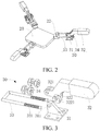
- the transverse force application member 30 includes a pivot seat 31, a pull handle 32, a clasp member 33 and a fixing member 34.
- the pivot seat 31 is fixedly mounted to the base body 11 and is disposed opposite to a corresponding one of the transverse force application mating members 22.
- a pivot shaft 311 is provided on the pivot seat 31.
- a pivot hole 321 is formed on the pull handle 32.
- the pivot hole 321 of the pull handle 32 is pivotally connected to the pivot shaft 311.
- the pull handle 32 is rotatable relative to the pivot seat 31 around the pivot shaft 311.
- An adjustment block 322 is provided on each of two sides of the pull handle 32.
- the adjustment blocks 322 are fixedly connected to the pull handle 32.
- An adjustment hole 3221 is formed on the adjustment block 322. The adjustment hole 3221 can change its position relative to the pivot hole 321 as the pull handle 32 rotates.
- pivot seat 31 may be omitted according to the actual situation.
- the pull handle 32 may be directly pivotally connected to the base body 11.
- the clasp member 33 is a structure in the shape of a Chinese character " ".
- An open loop end of the clasp member is mounted to the pull handle 32 and is rotatable with the pull handle 32.
- a closed loop end of the clasp member is used to snugly clasp the barb portion of the transverse force application mating member 22.
- the transverse force application member 30 tightly connects the vertical rod 20 to the base 10.
- Threaded portions 331 are respectively provided on two sides of the open loop end of the clasp member 33.
- the two threaded portions 331 respectively pass through the adjustment holes 3221 on two sides of the pull handle 32 and can move relative to the adjustment block 322 along the adjustment hole 3221 to adjust a length of the clasp member 33 protruding from the transverse force application mating member 22.
- Two fixing members 34 are respectively provided for each of the threaded portions 331.
- the two fixing members 34 are respectively located on two sides of one of the adjustment holes 3221 and threadedly mate with the threaded portion 331.
- Each of the fixing members 34 is rotatable and abuts against one side of the adjustment hole 3221.
- the clasp member 33 is fastened to the adjustment block 322.
- a corresponding one of the fixing members 34 is loosened to adjust the length of the clasp member 33 protruding from the transverse force application mating member 22, so as to change a tension force of the clasp member 33 when being snapped into the transverse force application mating member 22.
- the clasp member 33 is not limited to the structure in the shape of a Chinese character " ".
- the clasp member 33 may also be other structures that is tightly connected to the transverse force application mating member 22, for example, an L-shaped structure, a T-shaped structure, a U-shaped structure or the like.
- the fixing member 34 may also be omitted.
- the clasp member 33 is a structure for a frame body to be fixedly connected to a screw rod.
- the frame body is used to be snapped into the transverse force application mating member 22.
- the screw rod is directly threadedly connected to the adjustment block 322, so that the length of the clasp member 33 protruding from the transverse force application mating member 22 is adjusted.
- the clasp member 33 is rotatable relative to the pivot seat 31 with the pull handle 32 to change the position of the clasp member 33 relative to the transverse force application mating member 22.
- Rotating the pull handle 32 causes the closed loop end of the clasp member 33 to be snugly clasped to or detached from the transverse force application mating member 22.
- one of the clasp members 33 corresponds to one of the transverse force application mating members 22.
- Each of the pull handles 32 is rotated in a direction away from the vertical rod 20 around a corresponding one of the pivot shafts 311.
- Each of the clasp members 33 is snugly clasped to a corresponding one of the transverse force application mating members 22.
- the three clasp members 33 respectively apply transverse forces in different directions to the three transverse force application mating members 22 to prevent the movement of the vertical rod 20 relative to the base 10.
- the transverse forces are parallel to the base body 11.
- the vertical rod 20 is subjected to its own gravity. A bottom face of the vertical rod naturally abuts against the base body 11.
- the vertical rod 20 is fixed to the base body 11.
- a bottom of the pull handle 32 abuts against the pivot seat 31.
- the pivot seat 31 cannot continue to rotate about the pivot hole 321 in a direction away from the vertical rod 20.
- a vertical distance between the adjustment hole 3221 and the base body 11 is less than a vertical distance between the pivot hole 321 and the base body 11.
- the clasp member 33 and the transverse force application mating member 22 are locked.
- the pull handle 32 can be rotated about the pivot shaft 311 in the direction of the vertical rod 20.
- the clasp member 33 rotates with the pull handle 32 to change a position of the clasp member relative to the transverse force application mating member 22. That is to say, the clasp member 33 is detached from the transverse force application mating member 22.
- the vertical rod 20 can be detached from the base 10.
- the clasp members 33 of the three transverse force application members 30 need to be respectively snugly clasped to the three transverse force application mating members 22 to fixedly mount the vertical rod 20 to the base 10.
- the clasp members 33 of the three transverse force application members 30 may be respectively detached from the three transverse force application mating members 22 to detach the vertical rod 20 from the base 10.
- the quantity of the limiting components is two.
- the two limiting components are symmetrically disposed on two sides of the vertical rod 20.
- the two limiting components are located on the same straight line.
- Two transverse force application members 30 are respectively disposed on the base 10.
- the two transverse force application mating member 22 are respectively disposed on a bottom of the vertical rod.
- One of the transverse force application mating members 22 corresponds to one of the transverse force application members 30.
- Each of the transverse force application members 30 is fixedly mounted to the base body.
- Each of the transverse force application mating members 22 is fixedly connected to the vertical rod.
- Each of the transverse force application members 30 is snugly clasped to the transverse force application mating member 22.
- Each of the limiting components is fixed with relative positions of the vertical rod 20 and the base 10.
- Each of the transverse force application members 30 applies a symmetrical transverse force to the vertical rod 20.
- the vertical rod 20 is subjected to a balance force and fastened to the base 10.
- the two transverse forces are a pair of balance force.
- the transverse force application mating member 22 includes a barb portion.
- the barb portion is hook-shaped.
- the transverse force application mating member 22 is fixedly connected to the bottom of the vertical rod 20.
- the transverse force application member 30 is snugly clasped to the transverse force application mating member 22 to apply a pull force to the vertical rod 20.
- the base 10 is fixedly connected to the vertical rod 20.
- the vertical rod 20 includes a pedestal 21.
- the pedestal 21 is located at the bottom of the vertical rod 20.
- the vertical rod 20 is integrally formed.
- the pedestal 21 may be substantially a rectangular flat plate. Two ends of the pedestal 21 extend to two sides of the vertical rod 20 without transverse force. In other words, the pedestal 21 extends at least in opposite directions perpendicular to the balance force to increase a contact area between the vertical rod 20 and the base body 11.
- the vertical rod 20 can stand firmly on the base 10 and is not easy to fall to the two sides without subjected to forces relative to the base 10, so as to prevent the vertical rod 20 from being subjected to an unbalanced force on the two sides without the limiting component.
- the clasp members 33 of the two transverse force application members 30 need to be respectively snugly clasped to the two transverse force application mating members 22 to fixedly mount the vertical rod 20 to the base 10.
- the clasp members 33 of the two transverse force application members 30 may be respectively detached from the two transverse force application mating members 22 to detach the vertical rod 20 from the base 10.
- the transverse force application member 30 and the transverse force application mating member 22 may also adopt the structure shown in FIG. 12 .
- the transverse force application member 30 when the transverse force application member 30 is disposed on the vertical rod 20 and the transverse force application mating member 22 is disposed on the base 10, the transverse force application member 30 may be mounted to a specific position of the vertical rod 20 according to actual needs.
- the transverse force application member 30 is mounted to the pedestal 21, or the pedestal 21 is mounted to a side wall of the vertical rod 20.
- a limiting structure is provided between the vertical rod 20 and the base 10.
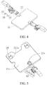
- the limiting structure includes a limiting protrusion 14 and a limiting opening 211a.
- the limiting protrusion 14 is provided on one of the base 10 and the vertical rod 20.
- the limiting opening 211a is provided on the other of the base 10 and the vertical rod 20.
- the limiting opening 211a can allow the limiting protrusion 14 to pass through the limiting opening 211a and snugly abut against the limiting protrusion 14 when the transverse force application member 30 applies the transverse force to the vertical rod 10.
- the vertical rod 20 is fixed to the base 10.
- the transverse force application member 30 may also be detached from the transverse force application mating member 22, so that the vertical rod 20 can be detached from the base 10.
- the quantity of the limiting components is one, and the limiting component is disposed on one side of the vertical rod 20.
- the limiting component includes a transverse force application member 30 and a transverse force application mating member 22a.
- the transverse force application member 30 is disposed on the base 10.
- the transverse force application mating member 22a is disposed on the vertical rod 20.
- the transverse force application member 30 is disposed opposite to the transverse force application mating member 22a.
- the transverse force application member 30 is fixedly mounted to the base body 11.
- the transverse force application mating member 22a is fixedly connected to the vertical rod 20.
- the transverse force application member 30 is snugly clasped to the transverse force application mating member 22a.
- the limiting component is fixed with relative positions of the vertical rod 20 and the base 10.
- the transverse force application member 30 applies a transverse force to the vertical rod 20.
- the vertical rod 20 includes a pedestal 21a.
- the pedestal 21a is located at the bottom of the vertical rod 20, and the vertical rod 20 is integrally formed.
- the pedestal 21a may be substantially a rectangular flat plate.
- the pedestal 21a extends around the vertical rod 20 to increase the contact area between the vertical rod 20 and the base body 11.
- the vertical rod 20 can stand firmly on the base body 11, thus preventing the vertical rod 20 from toppling when the calibration element is hung on the vertical rod.
- the transverse force application mating member 22a is fixedly connected to the pedestal 21a.
- the transverse force application mating member 22a is disposed opposite to the transverse force application member 30.
- the transverse force application mating member 22a is configured to be snugly clasped to the clasp member 33 of the transverse force application member 30.
- a bent portion of the transverse force application mating member 22a is disposed upward away from the pedestal 21a.
- a limiting protrusion 14 is provided on one of the base 10 and the vertical rod 20.
- a limiting opening 211a is provided on the other of the base 10 and the vertical rod 20.
- the limiting opening 211a allows the limiting protrusion 14 to pass through the limiting opening 211a and snugly abutting against the limiting protrusion 14 when the transverse force application member 30 applies the transverse force to the vertical rod 20.
- the limiting opening 211a may be approximately perforated.
- the limiting protrusion 14 may be approximately rod-shaped.
- the limiting opening 211a is formed on the pedestal 21a.
- the limiting protrusion 14 is fixedly connected to the base 10.
- two of the limiting openings 211a are provided on one side of the pedestal 21a.
- Two of the limiting protrusions 14 are respectively provided corresponding to the two limiting openings 211a on the base body 11.
- One of the transverse force application mating members 22a is disposed on the opposite side of the two limiting openings 211a and at the top of the pedestal 21a.
- the two limiting openings 211a and the transverse force application mating member 22a are distributed in an isosceles triangle.
- the limiting protrusion 14 can pass through the limiting opening 211a and then be snapped to the limiting opening 211a.
- the clasp member 33 of the transverse force application member 30 snugly clasps the transverse force application mating member 22a
- the transverse force applied by the transverse force application member 30 to the vertical rod 20 causes the limiting protrusion 14 to snugly abut against an inner side wall of the limiting opening 211a. That is, the mutual mating of the transverse force application member 30 and the limiting opening 211a as well as the limiting protrusion 14 can prevent the movement of the vertical rod 20 relative to the base 10.
- the vertical rod 20 is tightly fixed to the base 10.
- the limiting protrusion 14 has a cap-shaped end 141.
- the cap-shaped end 141 is fixedly connected to an end of the limiting protrusion 144.
- the cap-shaped end 141 is configured to abut against an edge of the limiting opening 211a. In other words, the cap-shaped end 141 abuts against an upper surface of the pedestal 21a and snugly presses the vertical rod 20 against the base 10 to prevent separation of the vertical rod 20 from the base 10 in a direction perpendicular to the base 10.
- the limiting protrusion 14 When the clasp member 33 of the transverse force application member 30 snugly clasps the transverse force application mating member 22a, the limiting protrusion 14 simultaneously snugly abuts against the inner side wall of the limiting opening 211a and the upper surface of the pedestal 21a.
- the vertical rod 20 is fixed to the base 10.
- a first abutting face 142 is provided for the cap-shaped end 141.
- a second abutting face 2113 is provided for the edge of the limiting opening 211a.
- the first abutting face 142 is mated with the second abutting face 2113.
- the first abutting face 142 snugly abuts against the second abutting face 2113 to generate a force that presses the vertical rod 20 against the base 10 in a direction perpendicular to the base 10.
- the limiting opening 211a can be closely connected to the limiting protrusion 14.
- the vertical rod 20 is snugly pressed against the base 10 to prevent a gap from being formed between the cap-shaped end 141 of the limiting protrusion 14 and the edge of the limiting opening 211a.
- first abutting face 142 and the second abutting face 2113 are both inverted conical faces.
- the cap-shaped end 141 can be close to the edge of the limiting opening 211a.
- the limiting protrusion 14 can apply a pressure to an inclined face of the vertical rod 20, thus balancing the force of the vertical rod 20 from the angle of the inclined face.
- the limiting opening 211a is a through hole composed of a larger hole 2111 and a smaller hole 2112 that are in radial communication with each other.
- the smaller hole 2112 is disposed farther from the transverse force application mating member 22a than the larger hole 2111.
- An aperture of the larger hole 2111 is greater than an aperture of the smaller hole 2112.
- the cap-shaped end 141 is a round cap-shaped end.
- a diameter of the cap-shaped end 141 is less than or equal to the aperture of the larger hole 2111 and greater than the aperture of the smaller hole 2112.
- a diameter of a rod of the limiting protrusion 14 is mated with the aperture of the smaller hole 2112.
- the limiting protrusion 14 can be snapped to the smaller hole 2112 after passing through the larger hole 2111.
- the first abutting face 142 of the cap-shaped end 141 abuts against the second abutting face 2113 of the smaller hole 2112.
- the two limiting protrusions 14 are caused to pass through the two larger holes 2111 respectively and then be snapped to the smaller holes 2112. Then the clasp member 33 of the transverse force application member 30 is snugly clasped to the transverse force application mating member 22a to fixedly mount the vertical rod 20 to the base 10. The clasp member 33 of the transverse force application member 30 may be detached from the clasp portion. Then the two limiting protrusions 14 are respectively detached from the two limiting openings 211a to detach the vertical rod 20 from the base 10.
- the transverse force application member 30 and the transverse force application mating member 22a may also adopt the structure shown in FIG. 12 .
- the pedestal 21a may be omitted.
- the limiting protrusion 14 or the limiting opening 211a may be directly provided on the vertical rod 20.
- the vertical rod is mated with one of the limiting components to fasten the vertical rod 20 to the base 10.
- the limiting protrusion 14 is disposed on the vertical rod 20.
- the limiting opening 211a is formed on the base 10.
- the limiting opening 211a can allow the limiting protrusion 14 to pass through the limiting opening 211a and snugly abut against the limiting protrusion 14 when the transverse force application member 30 applies the transverse force to the vertical rod 20.
- the vertical rod 20 is fastened to the base 10.
- the transverse force application member 30 is fixedly mounted to the vertical rod 20.
- the transverse force application mating member is fixedly connected to the base body 11.
- One of the transverse force application members 30 corresponds to one of the transverse force application mating members 22a.
- Each of the transverse force application members 30 may be respectively snugly clasped to a corresponding one of the transverse force application mating members.
- the vertical rod 20 is fixed to the base body 11.
- Each of the transverse force application members 30 may also be detached from the corresponding one of the transverse force application mating members.
- the vertical rod 20 can be detached from the base body 11.
- the quantity of limiting protrusions 14 and limiting openings may be selected according to actual needs.
- the quantity of the transverse force application mating member 30 may also be selected according to actual needs. As long as the transverse force application member 30 snugly clasps the transverse force application mating member, all of the limiting openings 211a can be mated with the corresponding limiting protrusions 14.
- the vertical rod 20 is fastened to the base 10.
- three limiting protrusions 14 and one transverse force application mating member are disposed at the bottom of the vertical rod 20.
- the limiting openings in a one-to-one correspondence with the three limiting protrusions 14 are disposed on the base 10.
- the three limiting openings and the transverse force application mating member are distributed in a prismatic shape.
- the limiting component is a push-pull structure.
- the limiting component connects the vertical rod 20 to the base 10 upon abutting.
- the limiting component includes a transverse force application member 30a and a transverse force application mating member 22b.
- the transverse force application mating member 22b includes a flange.
- the transverse force application member 30a may abut against one side face of the flange.
- the quantity of the limiting components is one.
- the limiting component is disposed on one side of the vertical rod 20.
- the transverse force application member 30a is disposed on the base 10.
- the transverse force application mating member 22b is disposed on the vertical rod 20.
- the transverse force application member 30 is disposed opposite to the transverse force application mating member 22a.
- the transverse force application member 30a is fixedly mounted to the base body 11.
- the transverse force application mating member 22b is fixedly connected to the vertical rod 20.
- the transverse force application member 30a snugly abuts against the transverse force application mating member 22b.
- the limiting component is fixed with relative positions of the vertical rod 20 and the base 10.
- the transverse force application member 30a applies a transverse pull force to the vertical rod 20.
- the vertical rod 20 includes a pedestal 21b.
- the pedestal 21b is located at the bottom of the vertical rod 20, and the vertical rod 20 is integrally formed.
- the transverse force application mating member 22b is fixedly connected to a top of the pedestal 21b and is disposed opposite to the transverse force application member 30a.
- Two limiting openings 211b are provided for the pedestal 21b. Two of the limiting protrusions 14 are correspondingly provided for the base body 11. One of the limiting openings 211b corresponds to one of the limiting protrusions 14. The two limiting openings 211b are located on opposite sides of the transverse force application mating member 22b. The two limiting openings 211b and the transverse force application mating member 22b are distributed in an isosceles triangle.
- the limiting opening 211b is a U-shaped through slot.
- the slot of the limiting opening 211b is disposed away from the transverse force application mating member 22b.
- a cap-shaped end 141 is provided on the limiting protrusion 14.
- a first abutting face 142 is provided for the cap-shaped end 141.
- a second abutting face 2113b is provided for the edge of the limiting opening 211b.
- the first abutting face 142 is mated with the second abutting face 2113b.
- the first abutting face 142 snugly abuts against the second abutting face 2113b.
- the limiting opening 211b can be closely connected to the limiting protrusion 14.
- the vertical rod 20 is snugly pressed against the base 10.
- the first abutting face 142 and the second abutting face 2113b are both inverted conical faces.
- the cap-shaped end 141 can be snugly attached to the edge of the limiting opening 211b.
- the limiting protrusion 14 can apply a pressure to an inclined face of the vertical rod 20, thus balancing the force of the vertical rod 20 from the angle of the inclined face.
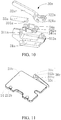
- the transverse force application member 30a includes a pivot seat 31a, a pull handle 32a, a push shaft 33a and a link 34a.
- the pivot seat 31a is fixedly mounted to the base body 11.
- a guide hole 311a is formed on a front end of the pivot seat 31a.
- the guide hole 311a is disposed opposite to the transverse force application mating member 22b.
- a pivot shaft 312a is provided on a rear end of the pivot seat 31a.
- a first pivot hole 321a and a second pivot hole 322a are formed on the pull handle 32a.
- the first pivot hole 321a and the second pivot hole 322a are disposed front and rear.
- the second pivot hole 322a of the pull handle 32a is pivotally connected to the pivot shaft 312a and is rotatable about the pivot shaft 312a relative to the pivot seat 31a.
- the push shaft 33a is slidably mounted to the guide hole 311a and can slide along the guide hole 311a relative to the pivot seat 31a.
- a third pivot hole 331a is formed at one end of the push shaft 33a.
- the third pivot hole 331a is disposed away from the transverse force application mating member 22b.
- the pivot seat 31a may be omitted.
- the pull handle 32a may be directly pivotally connected to the base body 11.
- the guide hole 311a may be directly provided on the base body 11.
- the push shaft 33a is slidably mounted to the guide hole 311a.
- a first rotating shaft 341a and a second rotating shaft 342a are respectively disposed at front and rear ends of the link 34a.
- the first rotating shaft 341a and the second rotating shaft 342a are respectively pivotally connected to the third pivot hole 331a of the push shaft 33a and the first pivot hole 321a of the pull handle 32a. Rotating the pull handle 32a causes the push shaft 33a to slide along the guide hole 311a within a certain stroke.
- the pull handle 32a is rotated about the pivot shaft 312a toward the vertical rod 20.
- the push shaft 33a slides toward the transverse force application mating member 22b along the guide hole 311a. Therefore, one end of the push shaft 33a is caused to abut against the transverse force application mating member 22b to fasten the vertical rod 20 to the base 10.
- a vertical distance between a pivot joint of the second rotating shaft 342a of the link 34a and the first pivot hole 321a of the pull handle 32a and the base body 11 is less than a vertical distance between a pivot joint of the first rotating shaft 341a of the link 34a and the third pivot hole 331a of the push shaft 33a and the base body 11.
- the pull handle 32a can be rotated about the pivot shaft 312a in a direction away from the vertical rod 20.
- the push shaft 33a is detached from the transverse force application mating member 22b along the guide hole 311a, thereby detaching the vertical rod 20 from the base 10.
- the transverse force application mating member 22b may be omitted.
- the transverse force application member 30a is configured to mate with the vertical rod 20.
- the transverse force application member 30 may directly abut against a side wall of the vertical rod 20.
- the pedestal 21b may be omitted.
- the limiting protrusion 14 or the limiting opening 211b may be directly disposed on the vertical rod 20.
- the vertical rod is mated with one limiting component to fasten the vertical rod 20 to the base 10.
- the quantity of the transverse force application members 30a may also be selected according to actual needs. For example, four transverse force application members 30a are regularly disposed around the vertical rod 20. In order to cause the push shaft 33a of the transverse force application member 30a to be tightly mated with the vertical rod 20, insertion holes disposed in a one-to-one correspondence with the four push shafts 33a may be disposed on the vertical rod 20. The insertion holes are blind holes.
- the transverse force application mating member 22b may be the insertion hole.
- the push shaft 33a abuts against the vertical rod 20
- the push shaft 33a is at least partially received in the insertion hole, and the vertical rod 20 is fastened to the base 10.
- the limiting opening 211b and the limiting protrusion 14 may also be omitted accordingly as required.
- the transverse force application member 30c is an eccentric wrench, to replace the transverse force application member 30a in the embodiment of the push-pull structure.
- the transverse force application member is configured to connect the vertical rod 20 to the base 10 in an abutting manner.
- the transverse force application mating member is at least a part of the vertical rod 20. That is to say, at least a part of a side face of the pedestal 21b.
- the other technical content is basically the same as the content of the embodiment of the push-pull structure.
- the transverse force application member 30c is disposed on the opposite side of the two limiting openings 211a.
- the transverse force application member 30c includes an abutting portion 31c and a pull handle 32c.
- the abutting portion 31c includes a curved abutting face 311c.
- An eccentric hole 312c is formed on the abutting portion 31c.
- the eccentric hole 312c deviates from a geometric contour center of the curved abutting face 311c.
- the pull handle 32c is fixedly connected to the abutting portion 31c.
- the eccentric hole 312c of the abutting portion 31c is pivotally connected to the base body 11.
- the curved abutting face 311c is disposed opposite to the side face of the pedestal 21b.
- the abutting portion 31c is rotatable about the eccentric hole 312c relative to the base body 11, to change relative positions of the curved abutting face 311c and the pedestal 21b.
- the pull handle 32c is rotated about the eccentric hole 312c in the direction toward the vertical rod 20.
- the curved abutting face 311c abuts against a side face of the pedestal 21b. Therefore, the vertical rod 20 is fastened to the base 10.
- the pull handle may be rotated about the eccentric hole 312c in a direction away from the vertical rod 20.
- the curved abutting face 311c is out of contact with the pedestal 21b, thereby detaching the vertical rod 20 from the base 10.
- the pedestal 21b may be omitted.
- the transverse force application member 30c is configured to mate with the vertical rod 20.
- the curved abutting face 311c of the abutting portion 31c may directly abut against a side wall of the vertical rod 20.
- the limiting component is a horizontal structure.
- the limiting component includes a transverse force application member 30d and a transverse force application mating member 22c.
- the transverse force application mating member 22c may be substantially perforated.
- the formed perforated structure includes a tapered inclined face.
- the vertical rod 20 includes a pedestal 21c.
- the pedestal 21c is located at the bottom of the vertical rod 20.
- the vertical rod 20 is integrally formed.
- the transverse force application mating member 22c is disposed on the pedestal 21c.
- the quantity of the transverse force application members 30d is three.
- the three transverse force application members 30d are regularly disposed around the vertical rod with the vertical rod 20 as the center.
- the three transverse force application members 30d are distributed in an isosceles triangle.
- Three transverse force application mating members 22c in a one-to-one correspondence with the three transverse force application members 30d are disposed on the pedestal 21c.
- the transverse force application mating members 22c are configured to be connected to the transverse force application members 30d.
- the transverse force application members 30d are fixedly connected to the vertical rod 20 and the pedestal 21c.
- the transverse force application mating member 22c includes a tapered inclined face, even though the force application direction of the transverse force application member 30d is vertically downward, a transverse force may still be applied to the pedestal 21c. It may be understood that, the transverse force application mating member 22c may further include inclined faces of other structures, as long as the transverse force can be applied to the pedestal 21c.
- the quantity of transverse force application members 30d is not limited to three.
- four transverse force application members 30d are respectively disposed on four sides of the vertical rod 20.
- the four transverse force application members 30d are distributed in a prismatic shape.
- the transverse force application member 30d includes a pivot seat 31d, a pull handle 32d, a side link 33d and a connector 34d.
- the pivot seat 31d is fixedly mounted to the base body 11.
- a first pivot shaft 311d is provided on a front end of the pivot seat 31d.
- a first pivot hole 312d is provided on a rear end of the pivot seat 31d.
- a first rotating shaft 331d and a second rotating shaft 332d are respectively provided on front and rear ends of the side link 33d.
- the second rotating shaft 332d is pivotally connected to the first pivot hole 312d.
- the side link 33d is rotatable about the first pivot hole 312d relative to the pivot seat 31d.
- a second pivot shaft 341d and a second pivot hole 342d are respectively provided above and below one end of the connector 34d.
- the second pivot hole 342d is pivotally connected to the first pivot shaft 311d of the pivot seat 31d.
- the connector 34d is rotatable about the first pivot shaft 311d relative to the pivot seat 31d.
- a fixing head 343d is provided on an other end of the connector 34d.
- the fixing head 343d is fixedly connected to the connector 34d.
- the fixing head 343d is used to be snugly clasped to the transverse force application mating member 22c, so that the vertical rod 20 is fastened to the base.
- the fixing head 343d includes a tapered inclined face.
- the tapered inclined face of the fixing head 343d is mated with the tapered inclined face of the transverse force application mating member 22c. Both the tapered inclined faces are disposed as an inverted tapered face.
- the tapered inclined face of the fixing head 343d presses the tapered inclined face of the transverse force application mating member 22c.
- the transverse force application member 30d presses the transverse force application mating member 22c against the base 10 while generating a transverse component force parallel to the base 10.
- One of the fixing heads 343d is disposed corresponding to one of the transverse force application mating members 22c.
- a third pivot hole 321d and a fourth pivot hole 322d are formed on the pull handle 32d.
- the third pivot hole 321d and the fourth pivot hole 322d are disposed front and rear.
- the third pivot hole 321d is pivotally connected to the second pivot shaft 341d of the fixing head 343d.
- the fourth pivot hole 322d is pivotally connected to the first rotating shaft 331d of the side link. Rotating the pull handle 32d causes the fixing head 343d to move up and down relative to the transverse force application mating member 22c.
- the pivot seat 31d, the side link 33d, the connector 34d and the pull handle 32d constitute a double-rocker mechanism.
- pivot seat 31d and the connector 34d may be omitted.
- One end of the side link 33d is pivotally connected to the base body 11.
- One end of the fixing head 343d is pivotally connected to the base body 11.
- the pull handle 32d is respectively pivotally connected to an other end of the side link 33d and an other end of the fixing head 343d.
- one of the fixing heads 343d corresponds to one of the transverse force application mating members 22c.
- Each of the pull handles 32d is pulled in a direction away from the vertical rod 20.
- Each of the connectors 34d rotates about the first pivot shaft 311d of a corresponding one of the pivot seats 31d.
- a corresponding one of the fixing heads 343d is snugly clasped to a corresponding one of the transverse force application mating members 22c from top to bottom.
- the three fixing heads 343d respectively apply constraint forces in different directions to the three transverse force application mating members 22c.
- the constraint forces can be resolved into a vertical pressure perpendicular to the base body 11 and a transverse pull force parallel to the base body 11, to prevent the movement of the vertical rod 20 relative to the base.
- the vertical rod 20 is subjected to its own gravity. The bottom face of the vertical rod naturally abuts against the base body 11. The vertical rod 20 is fastened to the base body 11.
- the third pivot hole 321d and the fourth pivot hole 322d of the pull handle 32d and the first pivot hole 312d of the pivot seat 31d are located on the same straight line.
- the mechanism is at the dead center position. No matter how much reacting force the pedestal 21c applies to the fixing head 343d, the fixing head 343d cannot be detached from the transverse force application mating member 22c.
- the pull handle 32d can be pulled toward the vertical rod 20, so that the fixing head 343d is detached from the transverse force application mating member 22c from bottom to top. In this way, the vertical rod 20 is detached from the base.
- the limiting opening 211a and the limiting protrusion 14 that are mated with each other may be respectively provided on the base 10 and the vertical rod 20. Then a transverse force application member 30d and a transverse force application mating member 22c are individually provided on the base 10 and the vertical rod 20. The transverse force application member 30d may be snapped to the transverse force application mating member 22c. The limiting protrusion 14 snugly abuts against the limiting opening 211a. The vertical rod 20 is fastened to the base 10.
- the limiting component is a clasp structure and includes a transverse force application member 30e.
- the transverse force application member 30e is mounted to a side face of the vertical rod 20.
- a fixing port 111 mated with the transverse force application member 30e is formed on the base body 11. The transverse force application member 30e snugly abuts against the fixing port 111 to apply a transverse force to the vertical rod 20.
- the transverse force application member 30e includes a pivot seat 31e, a pull handle 32e, an abutting portion 33e and a link 34e.
- the pivot seat 31e is fixedly mounted to the vertical rod 20.
- a first pivot shaft 311e and a second pivot shaft 312e are provided for the pivot seat 31e.
- the first pivot shaft 311e and the second pivot shaft 312e are disposed up and down.
- An inclined abutting face 313e is further provided for the pivot seat 31e.
- the inclined abutting face 313e is opposite to the first pivot shaft 311e and the second pivot shaft 312e.
- a first pivot hole 321e and a second pivot hole 322e are formed on the pull handle 32e.
- the first pivot hole 321e and the second pivot hole 322e are disposed up and down.
- the first pivot hole 321e of the pull handle 32e is pivotally connected to the first pivot shaft 311e.
- the pull handle 32e is rotatable about the first pivot shaft 311e relative to the pivot seat 31e.
- a third pivot hole 331e and a fourth pivot hole 332e are provided for the abutting portion 33e.
- the third pivot hole 331e is pivotally connected to the second pivot shaft 312e.
- the abutting portion 33e is rotatable about the second pivot shaft 312e relative to the pivot seat 31e.
- pivot seat 31e may be omitted according to the actual situation.
- the pull handle 32e and the abutting portion 33e may be directly pivotally connected to the vertical rod 20, respectively.
- the inclined abutting face 313e may be directly disposed on the vertical rod 20.
- a fifth pivot hole 341e and a sixth pivot hole 342e are disposed on two ends of the link 34e.
- the fifth pivot hole 341e may be pivotally connected to the second pivot hole 322e through a pin shaft.
- the sixth pivot hole 342e may be pivotally connected to the fourth pivot hole 332e through the pin shaft.
- the link 34e may rotate together with the pull handle 32e through the pin shaft.
- Rotating the pull handle 32e causes the sixth pivot hole 342e of the link 34e to drive, through the pin shaft, the abutting portion 33e to rotate about the second pivot shaft 312e relative to the pivot seat 31e while the link 34e is rotating about the first pivot shaft 311e.
- the abutting portion 33e snugly abuts against an inner side wall of the fixing port 111 or is detached from the inner side wall of the fixing port 111 during rotation.
- the abutting portion 33e simultaneously snugly abuts against the inclined abutting face 313e.
- the abutting portion 33e is locked.
- the abutting portion 33e snugly abuts against the inner side wall of the fixing port 111, the abutting portion 33e applies a transverse force to the vertical rod 20.
- the vertical rod 20 includes a pedestal 21d.
- the pedestal 21d is located at the bottom of the vertical rod 20.
- the vertical rod 20 is integrally formed.
- a limiting opening 221d is provided on the pedestal 21d.
- a limiting protrusion 14 mated with the limiting opening 221d is provided on the vertical rod 20.
- the limiting opening 221d can allow the limiting protrusion 14 to pass through and snugly abut against the limiting protrusion 14 when the transverse force application member 30e applies the transverse force to the vertical rod 20.
- the structure of the limiting opening 221d is basically the same as that of the limiting opening 211a of the embodiment shown in FIG. 5 to FIG. 6 . A difference is that the larger hole of the limiting opening 221d is disposed farther away from the transverse force application member 30e than the smaller hole.
- the larger hole and the smaller hole are disposed in a direction related to the direction of the transverse force applied by the transverse force application member 30e to the vertical rod 20.
- the structure of the limiting protrusion 14 is disposed in the same manner as that of the limiting protrusion 14 in the embodiments shown in FIG. 5 to FIG. 6 .
- limiting openings 221d are formed on the pedestal 21d.
- Four limiting protrusions 14 are correspondingly provided on the base body 11.
- One of the limiting openings 221d corresponds to one of the limiting protrusions 14.
- the quantity of the limiting openings 221d and the limiting protrusions 14 may be set according to actual needs. For example, the quantity may be two or three. Only one limiting opening 221d corresponds to one limiting protrusion 14. The limiting opening 221d may also be disposed on the base body 11. The limiting protrusion 14 is correspondingly disposed on the pedestal 21d.
- the pull handle 32e is rotated about the first pivot shaft 311e in the direction toward the vertical rod 20.
- One end of the abutting portion 33e rotates about the second pivot shaft 312e toward a side wall of the fixing port 111.
- One end of the abutting portion 33e abuts against the side wall of the fixing port 111.
- the transverse force application member 30e applies a transverse force to the vertical rod 20.
- the first abutting face of the limiting protrusion 14 snugly abuts against the second abutting face of the limiting opening 221d.
- the limiting opening 221d is tightly connected to the limiting protrusion 14, and the vertical rod 20 is snugly pressed against the base 10. In this way, the vertical rod 20 is fastened to the base 10.
- one end of the abutting portion 33e having the fourth pivot hole 332e abuts against the inclined abutting face 313e.
- the transverse force application member 30e and the fixing port 111 are in a locked state. Even if a side wall of the fixing port 111 applies a reverse push force to one end of the abutting portion 33e, the end of the abutting portion 33e cannot be detached from the side wall of the fixing port 111.
- the pull handle may be rotated about the first pivot shaft 311e in a direction away from the vertical rod 20.
- One end of the abutting portion 33e rotates about the second pivot shaft 312e to detach one end of the abutting portion 33e from one side wall of the fixing port 111. In this way, the vertical rod 20 is detached from the base 10.
- the transverse force application member 30e may be disposed on the base body 11.
- the fixing port 111 is disposed on the pedestal 21d.
- the transverse force application member 30e snugly abuts against the fixing port 111 to apply a transverse force to the vertical rod 20.
- the limiting component includes a transverse force application member 30f.
- the transverse force application member 30f is mounted to the base body 11 and is located on one side of the vertical rod 20.
- the transverse force application member 30f snugly abuts against the vertical rod 20 to apply the transverse force to the vertical rod 20.
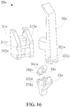
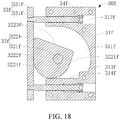
- the transverse force application member 30f includes a mounting box 31f, a cam mechanism 32f, an abutting mechanism 33f and an elastic member 34f.
- the mounting box 31f is fixedly mounted to the base body 11.
- a receiving cavity 311f for mounting the cam mechanism 32f and a counterbore 312f for mounting the elastic member 34f and the abutting mechanism 33f are provided in the mounting box 31f.
- the cam mechanism 32f is rotatably mounted to the mounting box 31f and is rotatable about a rotation axis of the mounting box relative to the mounting box 31f.
- the rotation axis is perpendicular to the base body 11.
- the cam mechanism 32f includes a pull handle 321f and a cam 322f.
- the cam 322f is an eccentric cam.
- the pull handle 321f can pass through the mounting box 31f through a rotating shaft to be connected to the cam 322f.
- the cam 322f is at least partially received in the receiving cavity 311f.
- the pull handle 321f is placed outside the receiving cavity 311f.
- the cam 322f can be synchronously driven by rotating the pull handle 321f to rotate in the receiving cavity 311f.
- the cam 322f includes a first plane 3221f, a second plane 3222f, a third plane 3223f and an arc face 3224f in arc transition with the first plane 3221f and the second plane 3222f.
- the first plane 3221f, the arc face 3224f, the second plane 3222f and the third plane 3223f are sequentially connected to form a peripheral side face of the cam 322f.
- the receiving cavity 311f is roughly a quarter-circle sector.
- a first step face 313f and a second step face 314f are provided in the receiving cavity 311f.
- the first step face 313f is connected to the sector-shaped arc face 3224f.
- the third plane 3223f may at least partially abut against the first step face 313f.
- the first step face 313f is used to limit a rotation angle of the cam 322f.
- a height difference between the first step face 313f and the second step face 314f is used to allow a connecting part of the first plane 3221f and the third plane 3223f to rotate.
- the abutting mechanism 33f is slidably mounted to the mounting box 31f and is slidable toward the vertical rod 20 or away from the vertical rod 20 relative to the mounting box 31f upon abutting of the cam mechanism 32f.
- the abutting mechanism 33f includes a pushing block 331f and an urging post 332f.
- One end of the urging post 332f is fixedly connected to the pushing block 331f.
- the urging post 332f is slidably mounted to the counterbore 312f.
- the urging post 332f is at least partially received in the counterbore 312f.
- the push block 331f is placed outside the counterbore 312f in an axial direction and is disposed opposite to one side face of the vertical rod 20.
- a limiting portion is provided on an other end of the urging post 332f. The limiting portion is received in a part of the counterbore 312f with a larger aperture, so that the abutting mechanism 33f cannot be removed from the mounting box 31f.
- the elastic member 34f elastically abuts between the abutting mechanism 33f and the mounting box 31f.
- the cam 322f is detached from the push block 331f
- the cam 322f is detached from the vertical rod 20 under the elastic force of the elastic member 34f and returns to an initial position.
- the elastic member 34f is sleeved on the urging post 332f and is accommodated in the part of the counterbore 312f with a larger aperture.
- One end of the elastic member 34f abuts against the limiting portion.
- An other end of the elastic member 34f is limited to an end face of the counterbore 312f.
- the elastic member 34f may be a compression spring, a leaf spring or the like.
- the two urging posts 332f are respectively fixedly connected to two ends of the push block 331f through threads.
- the cam mechanism 32f is located between the two urging posts 332f.
- the pull handle 321f When the pull handle 321f is rotated to cause the push block 331f to be pressed by the cam 322f to move away from the mounting box 31f, the limiting portion and the end face of the counterbore 312f squeeze the elastic member 34f to compress the elastic member 34f.
- the pull handle 321f When the pull handle 321f is rotated to cause the cam 322f to move away from the push block 331f, the elastic member 34f restores deformation. Under the elastic force of the elastic member 34f, the urging post 332f drives the push block 331f to return to the initial position.
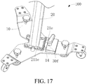
- the vertical rod 20 includes a pedestal 21e.
- the pedestal 21e is located at the bottom of the vertical rod 20.
- the vertical rod 20 is integrally formed.
- the mounting box 31f and the pedestal 21e are disposed at a predetermined distance to allow the push block 331f to abut against or be detached from the pedestal 21e.
- the push block 331f is disposed opposite to one side face of the pedestal 21e.
- a limiting opening 211e is provided on the pedestal 21e.
- a limiting protrusion 14 mated with the limiting opening 211e is provided on the base body 11.
- the limiting opening 211e can allow the limiting protrusion 14 to pass through and snugly abut against the limiting protrusion 14 when the transverse force application member 30f applies the transverse force to the vertical rod 20.
- the structure of the limiting opening 211e is basically the same as that of the limiting opening 211a of the embodiment shown in FIG. 5 to FIG. 6 . A difference is that the larger hole of the limiting opening 211e is disposed farther away from the transverse force application member 30f than the smaller hole.
- the larger hole and the smaller hole are disposed in a direction related to the direction of the transverse force applied by the transverse force application member 30f to the vertical rod 20.
- the structure of the limiting protrusion 14 is disposed in the same manner as that of the limiting protrusion 14 in the embodiments shown in FIG. 5 to FIG. 6 .
- limiting openings 211e are formed on the pedestal 21e.
- Four limiting protrusions 14 are correspondingly provided on the base body 11.
- One of the limiting openings 211e corresponds to one of the limiting protrusions 14.
- the pull handle 321f may be rotated counterclockwise.
- the cam 322f rotates about its rotation axis to the second plane 3222f to overlap with the push block 331f in parallel.
- the push block 331f is pushed against the pedestal 21e by the cam 322f to snugly abut against the side face of the pedestal 21e.
- the elastic member 34f is in a compressed state.
- the transverse force application member 30f applies a transverse force to the vertical rod 20.
- the first abutting face of the limiting protrusion 14 snugly abuts against the second abutting face of the limiting opening 211e.
- the limiting opening 211e is tightly connected to the limiting protrusion 14.
- the vertical rod 20 is snugly pressed against the base, thereby fastening the vertical rod 20 to the base. Since the cam 322f is an eccentric cam, when the second plane 3222f and the push block 331f overlap in parallel, the cam 322f is in a locked state. Even if the pedestal 21e applies a reverse push force to the push block 331f, the push block 331f cannot be detached from the pedestal 21e.
- the pull handle 321f may be rotated in a clockwise direction.
- the cam 322f rotates about its rotation axis to the third plane 3223f to abut against the second step face 314f.
- the cam 322f is detached from the push block 331f.
- the push block 331f is restored to the initial position under the elastic force of the elastic member 34f. That is to say, the push block 331f is detached from the pedestal 21e.
- the vertical rod 20 can be detached from the base.
- a positioning structure can be disposed between the vertical rod 20 and the base.
- a groove or a concave face or a positioning hole, etc. is provided on the vertical rod 20.
- a convex rail or a convex face or a positioning post, etc. is provided on the base 10.
- the vertical rod 20 can be quickly placed in an accurate position through the positioning structure.
- the positioning structure can also limit the vertical rod 20 to a certain extent.
Landscapes
- Engineering & Computer Science (AREA)
- General Engineering & Computer Science (AREA)
- Physics & Mathematics (AREA)
- General Physics & Mathematics (AREA)
- Mechanical Engineering (AREA)
- Analytical Chemistry (AREA)
- Life Sciences & Earth Sciences (AREA)
- Chemical & Material Sciences (AREA)
- Health & Medical Sciences (AREA)
- Biochemistry (AREA)
- General Health & Medical Sciences (AREA)
- Immunology (AREA)
- Pathology (AREA)
- Plasma & Fusion (AREA)
- High Energy & Nuclear Physics (AREA)
- Clamps And Clips (AREA)
- Mutual Connection Of Rods And Tubes (AREA)
Abstract
Description
- The present application claims priority to
Chinese Patent Application No. 201910214384.X, filed with China National Intellectual Property Administration on March 20, 2019 Chinese Patent Application No. 201910375451.6, filed with China National Intellectual Property Administration on May 7, 2019 - The present application relates to the field of automobile correction, and in particular, to a calibration bracket.
- After customers purchase a correction device, some assembling work usually needs to be done. A more common method on the market is a method of locking screws. Under normal conditions, the device is not frequently moved after being assembled, but some customers need frequent transportation. If the device is not disassembled for carrying, the device is heavy and takes up a lot of space, which is not convenient for transportation. If frequently removed and locked, the screws are easy to fail, and the process of mounting and removal is more troublesome. Therefore, a calibration bracket that can be easily removed and ensure the stability of the device is required.
- In order to overcome the shortcomings of the prior art, embodiments of the disclosure provide a calibration bracket, which can implement functions of rapid disassembly and mounting.
- The embodiments of the disclosure adopt the following technical solution to resolve the technical problem.
a calibration bracket, including: - a base;
- a vertical rod detachably mounted to the base;
- a transverse force application member disposed on one of the base and the vertical rod; and
- a transverse force application mating member disposed on the other of the base and the vertical rod, the transverse force application mating member being configured to be mated with the transverse force application member to apply, to the vertical rod, a transverse force parallel to the base.
- A limiting protrusion is provided on one of the base and the vertical rod. A limiting opening is provided on the other of the base and the vertical rod. The limiting opening allows the limiting protrusion to pass through the limiting opening and snugly abuts against the limiting protrusion when the transverse force application member applies the transverse force to the vertical rod.
- In some embodiments, the limiting opening is a through hole composed of a larger hole and a smaller hole that are in communication with each other, and the limiting protrusion is snapped to the smaller hole after passing through the larger hole.
- In some embodiments, the limiting opening is a U-shaped slot.
- In some embodiments, the limiting protrusion has a cap-shaped end configured to prevent separation of the vertical rod from the base in a direction perpendicular to the base when the limiting protrusion snugly abuts against the limiting opening.
- In some embodiments, the cap-shaped end includes a first abutting face, and the limiting opening includes a second abutting face, the first abutting face being mated with the second abutting face, and
when the transverse force application member applies the transverse force to the vertical rod, the first abutting face snugly abutting against the second abutting face, so that the vertical rod is snugly pressed against the base. - In some embodiments, the transverse force application member includes a pull handle and a clasp member,
- the pull handle being pivotally connected to the base and being rotatable about a pivot joint,
- one end of the clasp member being connected to the pull handle and being rotatable with the pull handle, and
- rotating the pull handle causing an other end of the clasp member to be snugly clasped to or be detached from the transverse force application mating member.
- In some embodiments, the pull handle has an adjustment hole. The clasp member passes through the adjustment hole, is movable along the adjustment hole and is fixed to a preset position.
- In some embodiments, the transverse force application mating member includes a barb portion fixedly connected to the vertical rod. The clasp member is snugly clasped to the barb portion. The base is fixedly connected to the vertical rod.
- In some embodiments, the transverse force application member includes a pull handle, a link and a push shaft,
- the pull handle being pivotally connected to the base and being rotatable about a pivot joint,
- the push shaft being slidably mounted in a guide hole provided on the base,
- two ends of the link being respectively pivotally connected to the pull handle and the push shaft, and
- rotating the pull handle causing the push shaft to slide along the guide hole, so as to abut against or be detached from the transverse force application mating member.
- In some embodiments, the transverse force application mating member includes a flange. The push shaft abuts against the flange. The base is fixedly connected to the vertical rod.
- In some embodiments, the vertical rod includes a pedestal. The transverse force application mating member is a perforated structure disposed on the pedestal or the base. The perforated structure includes an inclined face. The transverse force application member is snugly snapped to the inclined face of the transverse force application mating member. The base is fixedly connected to the vertical rod.
- According to another aspect, a calibration bracket is provided, including:
- a base;
- a vertical rod detachably mounted to the base; and
- a transverse force application member disposed on one of the base and the vertical rod, the transverse force application member being configured to be mated with the vertical rod to apply, to the vertical rod, a transverse force parallel to the base.
- A limiting protrusion is provided on one of the base and the vertical rod. A limiting opening is provided on the other of the base and the vertical rod. The limiting opening allows the limiting protrusion to pass through the limiting opening and snugly abuts against the limiting protrusion when the transverse force application member applies the transverse force to the vertical rod.
- According to another aspect, a calibration bracket is provided, including:
- a base;
- a vertical rod detachably mounted to the base, the vertical rod including a pedestal;
- at least two transverse force application members disposed on one of the base and the vertical rod; and
- at least two transverse force application mating members disposed on the other of the base and the vertical rod, each of the transverse force application mating members being configured to be connected to a corresponding one of the transverse force application members to apply, to the vertical rod, a transverse force parallel to the base.
- All transverse forces applied to the vertical rod are combined into a pair of balance forces on a plane parallel to the base. The pedestal extends at least in opposite directions perpendicular to the pair of balance forces.
- According to another aspect, a calibration bracket is provided, including:
- a base;
- a vertical rod detachably mounted to the base;
- at least three transverse force application members disposed on one of the base and the vertical rod; and
- at least three transverse force application mating members disposed on the other of the base and the vertical rod, each of the transverse force application mating members being configured to be connected to a corresponding one of the transverse force application members to apply, to the vertical rod, a transverse force parallel to the base, so that the vertical rod is fixed to the base.
- All acting forces applied to the vertical rod are combined into a first pair of balance forces and a second pair of balance forces. The first pair of balance forces are perpendicular to the second pair of balance forces.
- Compared with the prior art, the calibration bracket provided in the embodiments of the disclosure includes a transverse force application member and a transverse force application mating member. The transverse force application member is disposed on one of the base and the vertical rod. The transverse force application mating member is disposed on the other of the base and the vertical rod and is configured to be connected to the transverse force application member. The transverse force application mating member applies, to the vertical rod, a force parallel to the base. A limiting protrusion is provided on one of the base and the vertical rod. A limiting opening is provided on the other of the base and the vertical rod. The limiting opening can allow the limiting protrusion to pass through the limiting opening and snugly abut against the limiting protrusion when the transverse force application member applies a transverse force to the vertical rod. The vertical rod is fixed to the base. The transverse force application member can also be detached from the transverse force application mating member. This causes the vertical rod to be detached from the base. The connection between the vertical rod and the base by using the transverse force application member and the transverse force application mating member and the mating of the limiting protrusion and the limiting opening cause the vertical rod to be quickly mounted to or be detached the base. Therefore, the calibration bracket is easy to assemble and transport.
- One or more embodiments are exemplarily described with reference to the corresponding figures in the accompanying drawings. The descriptions are not to be construed as limiting the embodiments. Elements in the accompanying drawings that have same reference numerals are represented as similar elements. Unless otherwise particularly stated, the figures in the accompanying drawings are not drawn to scale.
-
FIG. 1 is a schematic structural diagram of a calibration bracket according to an embodiment of the disclosure. -
FIG. 2 is a schematic structural diagram ofFIG. 1 omitting an upper part of a base and a vertical rod. -
FIG. 3 is a structural exploded view of a transverse force application member ofFIG. 1 . -
FIG. 4 is a schematic structural diagram of another calibration bracket according to some embodiments of the disclosure, where the upper part of the base and the vertical rod is omitted. -
FIG. 5 is a schematic structural diagram of another calibration bracket according to some embodiments of the disclosure, where the upper part of the base and the vertical rod is omitted. -
FIG. 6 is a schematic structural diagram of a pedestal and a limiting protrusion ofFIG. 5 . -
FIG. 7 is a schematic diagram of mating of a limiting protrusion and a limiting opening of another calibration bracket according to some embodiments of the disclosure. -
FIG. 8 is a schematic structural diagram of another calibration bracket according to some embodiments of the disclosure, where the upper part of the base and the vertical rod is omitted. -
FIG. 9 is a schematic structural diagram of a pedestal and a limiting protrusion ofFIG. 8 . -
FIG. 10 is a structural exploded view of a transverse force application member ofFIG. 8 . -
FIG. 11 is a schematic structural diagram of another calibration bracket according to some embodiments of the disclosure, where the upper part of the base and the vertical rod is omitted. -
FIG. 12 is a schematic structural diagram of another calibration bracket according to some embodiments of the disclosure, where the upper part of the base and the vertical rod is omitted. -
FIG. 13 is an exploded view of a transverse force application member ofFIG. 12 . -
FIG. 14 is a schematic structural diagram of another calibration bracket according to some embodiments of the disclosure. -
FIG. 15 is a cross-sectional view of a partial structure ofFIG. 14 . -
FIG. 16 is a structural exploded view of a transverse force application member. -
FIG. 17 is a schematic structural diagram of another calibration bracket according to some embodiments of the disclosure. -
FIG. 18 is a cross-sectional view of a transverse force application member ofFIG. 17 . -
FIG. 19 is an exploded view of a transverse force application member ofFIG. 17 . - For ease of understanding the disclosure, the disclosure is described in more detail below with reference to the accompanying drawings and specific embodiments. It should be noted that, when a component is expressed as "being fixed to" another component, the component may be directly on the another component, or one or more intermediate components may exist between the component and the another component. When one component is expressed as "being connected to" another component, the component may be directly connected to the another component, or one or more intermediate components may exist between the component and the another component. The terms "vertical", "horizontal", "left", "right", "inner", "outside", and similar expressions used in this specification are merely used for an illustrative purpose.
- Unless otherwise defined, meanings of all of the technical and scientific terms used in this specification are the same as those usually understood by those skilled in the art of the disclosure. The terms used in the specification of the disclosure are merely intended to describe objectives of the specific embodiment, and are not intended to limit the disclosure. The term "and/or" used in this specification includes any or all combinations of one or more related listed items.
- To make the objectives, technical solutions, and advantages of the disclosure clearer and more comprehensible, the following further describes the disclosure in detail with reference to the accompanying drawings and embodiments. It should be understood that the specific embodiments described herein are merely used to explain the disclosure but are not intended to limit the disclosure.
- Referring to
FIG. 1 , acalibration bracket 100 provided in an embodiment of the disclosure includes abase 10, avertical rod 20, a transverseforce application member 30 and a transverse forceapplication mating member 22. Thevertical rod 20 is detachably mounted to the base 10 through a limiting component. The limiting component includes a transverseforce application member 30 and a transverse forceapplication mating member 22. The transverseforce application member 30 is disposed on one of thebase 10 and thevertical rod 20. The transverse forceapplication mating member 22 is disposed on the other of thebase 10 and thevertical rod 20. The transverse forceapplication mating member 22 is configured to be connected to the transverseforce application member 30 to apply, to thevertical rod 20, a force parallel to the base. When the transverseforce application member 30 applies a constraint force to thevertical rod 20, the transverseforce application member 30 can resolve at least a transverse pull force on a plane parallel to thebase 10. At least two of the transverseforce application members 30 respectively mate with a corresponding one of the transverse forceapplication mating members 22. Thevertical rod 20 can be fastened to thebase 10 under the constraints of different transverse pull forces. - The application of "a transverse force" as used in this specification means that at least one transverse component force can be generated between the vertical rod and the base through the mating of the corresponding transverse force application member and the transverse force application mating member. In other words, an acting force actually applied by the transverse force application member to the vertical rod may be set at an oblique angle to the base, as long as the acting force can resolve the transverse force on a plane parallel to the base. The transverse force may be a pull force or a push force. For example, in
FIG. 12 described later, although an application direction of the transverseforce application member 30d itself is vertically downward, since the transverse forceapplication mating member 22c includes an inclined face, a "transverse force" may also be generated between the vertical rod and the base. A mechanism that can generate the above "transverse force" is referred to as a "transverse force application member". - The
calibration bracket 100 may be configured to hang a calibration element, for example, a multi-line laser emitter, a calibration target, a radar reflection or absorption device, and the like, to calibrate various vehicle-mounted sensors such as a front vehicle camera, an anti-collision radar, or the like. - The
base 10 includes abase body 11, aroller 12 and aheight adjustment member 13. - The
base body 11 is triangular claw-shaped and includes three claws extending in three different directions. Thevertical rod 20 is detachably connected to thebase body 11. - The
roller 12 is mounted to the bottom surface of thebase body 11. There are threerollers 12. Each of therollers 12 is mounted to a tail end of a corresponding one of the claws to facilitate movement of thebase body 11. In this embodiment, theroller 12 is a universal moving roller, so that thebase body 11 can move in any direction. - The
height adjustment member 13 is mounted to thebase body 11 for adjusting the height of thebase body 10. In this embodiment, theheight adjustment member 13 is an adjustment knob. There are three height adjustment members. There is at least one screw rod under the knob. The screw rod is in screw-thread fit with a through hole at thebase body 11 to implement height adjustment of thebase body 10 by rotating the knob. Each of theheight adjustment members 13 is mounted to a corresponding one of the claws and is close to a corresponding one of therollers 12. The threeheight adjustment members 13 are distributed in a regular triangle. - It may be understood that, in some other embodiments, the shape of the
base body 11 may be changed according to actual needs, and is not limited to being triangular claw-shaped. For example, when thecalibration bracket 100 is used to calibrate the radar, thebase body 11 preferably uses a rectangular or rectangular-like structure. Two sides of thebase body 11 respectively extend in their length directions to balance the force acting on the base 10 when a heavier radar calibration member is hung on thecalibration bracket 100, to prevent the base 10 from causing thecalibration bracket 100 to fall due to the uneven force. A size of the base 10 may be changed according to actual needs. Since thevertical rod 20 is detachably mounted to thebase 10, and thevertical rod 20 and the base 10 may also be conveniently put into a vehicle after disassembly, thebase 10 may be a structure with a larger size to adapt to the calibration element with a larger size. Quantities of therollers 12 and theheight adjustment members 13 may be increased or decreased according to actual needs. For example, the triangular-claw-shapedbase body 11 may be provided with twoheight adjustment members 13 and mated with a foot with a fixed height to adjust an angle of thebase body 11. - The
vertical rod 20 is used to connect the calibration element to implement the function of thecalibration bracket 100 calibrating the vehicle-mounted sensor. Thevertical rod 20 is a square tube. On the one hand, an overall weight of thecalibration bracket 100 can be reduced. On the other hand, thevertical rod 20 may include a fixed vertical rod and a movable vertical rod. The fixed vertical rod is detachably mounted to thebase 10. The movable vertical rod is movably mounted to the fixed vertical rod. The movable vertical rod is movable relative to the fixed vertical rod in a length direction of the fixed vertical rod and is fixed at a certain position. Thevertical rod 20 can adjust its own length as required to meet different calibration requirements. The movable vertical rod serves as an inner rod and may be disposed in the fixed vertical rod. Alternatively, the movable vertical rod serves as an outer rod and is sleeved on the fixed vertical rod. The movable vertical rod is sleeved on and connected to the fixed vertical rod. In this way, the height of thevertical rod 20 can be reduced to nearly half of the original height to facilitate transportation. - It may be understood that, in some other embodiments, a beam assembly with functions of unfolding and folding may be provided on the
vertical rod 20. When the beam assembly is unfolded on thevertical rod 20, the calibration element may be hung on the beam assembly. When the beam assembly is folded on thevertical rod 20, the volume of thecalibration bracket 100 can be reduced to facilitate transportation. - It may be understood that the
vertical rod 20 is not limited to a square tube. Thevertical rod 20 may also be a tube of other shapes, for example, a round tube, an elliptical or special-shaped tube, and the like. - The transverse
force application member 30 may be connected to the transverse forceapplication mating member 22 to apply, to thevertical rod 20, a transverse pull force parallel to the base to prevent the movement of thevertical rod 20 relative to thebase 10. That is to say, thevertical rod 20 is fixed to thebase 10. - The transverse
force application member 30 and the transverse forceapplication mating member 22 may also adopt the structure shown inFIG. 12 . For details, reference may be made to the following embodiments. - It may be understood that the quantity of limiting components may be selected according to actual needs. One transverse
force application member 30 is correspondingly connected to one transverse forceapplication mating member 22, as long as all transverse forces applied by all transverseforce application members 30 to thevertical rod 20 can cause thevertical rod 20 to be subjected to a balance force and to be fastened to thebase body 11. In other words, all of the transverse forces act together to prevent the movement of thevertical rod 20 relative to thebase body 11. Thevertical rod 20 is fixedly mounted to thebase 10. - It may be understood that even when a certain amount of external force is applied to the
vertical rod 20, thevertical rod 20 can still be fastened to the base 10 through connection to the limiting component. For example, when the calibration element is hung on thevertical rod 20, the center of gravity of the calibration element and the geometric contour center of a support face of thevertical rod 20 standing on the base 10 do not overlap. Therefore, thevertical rod 20 may be caused to have a tendency to fall towards a certain direction relative to thebase 10. At this point, the corresponding transverseforce application member 30 is fixed with relative positions of thebase 10 and thevertical rod 20. The transverseforce application member 30 can increase its acting force to thevertical rod 20 in an opposite direction. The acting force is applied to balance the force applied to thevertical rod 20, so that thevertical rod 20 stands firmly on thebase 10. It may be understood that thevertical rod 20 can move relative to the base 10 only when the external force exceeds the load of the limiting component to such an extent that the structure of the limiting component is destroyed and the connection between thevertical rod 20 and thebase 10 is cut off. Each of the transverse forces applied to thevertical rod 20 may be removed. That is to say, the transverseforce application member 30 is detached from the transverse forceapplication mating member 22. That is to say, the connection to the limiting component between thevertical rod 20 and thebase 10 is cut off to detach thevertical rod 20 from thebase 10. - Referring to
FIG. 2 and FIG. 3 together, in this embodiment, the limiting component is a latch structure. The limiting component connects thevertical rod 20 to thebase 10 by using a buckle. The limiting component includes a transverseforce application member 30 and a transverse forceapplication mating member 22. - In this embodiment, the quantity of limiting components is three. The three limiting components are regularly distributed with the
vertical rod 20 as the center. Since thevertical rod 20 is a square tube, preferably, the two limiting components are respectively disposed at two adjacent corners of the bottom of thevertical rod 20, and are respectively located on extension lines of two diagonals of the bottom of thevertical rod 20. The other limiting component is disposed on the opposite side of the two adjacent corners, and is perpendicular to the side line and located at a midpoint position of the side line. The three limiting components are distributed in an isosceles triangle. - Three transverse
force application members 30 are respectively disposed on thebase 10. The three transverse forceapplication mating member 22 are respectively disposed on a bottom of thevertical rod 20. One of the transverse forceapplication mating members 22 corresponds to one of the transverseforce application members 30. - Each of the transverse
force application members 30 is fixedly mounted to thebase body 11. Each of the transverseforce application members 30 is snugly clasped to a corresponding one of the transverse forceapplication mating members 22. Each of the limiting components is fixed with relative positions of thevertical rod 20 and thebase 10. Each of the transverseforce application members 30 applies a transverse force to thevertical rod 20. The three pull forces cause thevertical rod 20 to be subjected to a balance force and to be fastened to thebase body 11. The three transverse forces are all arranged in parallel with thebase body 11. Thevertical rod 20 is subjected to a balance force in a direction parallel to thebase body 11. When thevertical rod 20 is subjected to an external force and has a tendency to move in a certain direction relative to thebase body 11, the corresponding one or two of the transverseforce application members 30 will increase the transverse force opposite to the direction, to balance the external force applied to thevertical rod 20. Thevertical rod 20 remains stationary relative to thebase body 11. - It may be understood that the acting force applied by the transverse
force application member 30 to thevertical rod 20 may actually be arranged at an oblique angle to thebase body 11. For example, the transverseforce application member 30 applies an oblique downward acting force to thevertical rod 20. The acting force is parallel to the transverse force of thebase body 11 for preventing movement of thevertical rod 20 in a direction parallel to thebase body 11. Thevertical rod 20 is stationary relative to thebase body 11. The acting force is perpendicular to the component force of thebase body 11 for causing the bottom of thevertical rod 20 to press against thebase body 11. - The transverse force
application mating member 22 includes a barb portion. The barb portion is hook-shaped. The transverse forceapplication mating member 22 is fixedly connected to the bottom of thevertical rod 20. The transverseforce application member 30 is snugly clasped to the transverse forceapplication mating member 22 to apply a transverse force to thevertical rod 20. Thebase 10 is fixedly connected to thevertical rod 20. Preferably, a bent part of the transverse forceapplication mating member 22 is disposed upward away from thebase body 11, to facilitate clasping of the transverseforce application member 30 to the barb portion of the transverse forceapplication mating member 22. A bottom of the transverse forceapplication mating member 22 abuts against thebase body 11. Thevertical rod 20 is not easy to tilt relative to thebase body 11. - The transverse
force application member 30 includes apivot seat 31, apull handle 32, aclasp member 33 and a fixingmember 34. - The
pivot seat 31 is fixedly mounted to thebase body 11 and is disposed opposite to a corresponding one of the transverse forceapplication mating members 22. Apivot shaft 311 is provided on thepivot seat 31. - A
pivot hole 321 is formed on thepull handle 32. Thepivot hole 321 of thepull handle 32 is pivotally connected to thepivot shaft 311. The pull handle 32 is rotatable relative to thepivot seat 31 around thepivot shaft 311. Anadjustment block 322 is provided on each of two sides of thepull handle 32. The adjustment blocks 322 are fixedly connected to thepull handle 32. Anadjustment hole 3221 is formed on theadjustment block 322. Theadjustment hole 3221 can change its position relative to thepivot hole 321 as thepull handle 32 rotates. - It may be understood that, the
pivot seat 31 may be omitted according to the actual situation. The pull handle 32 may be directly pivotally connected to thebase body 11. - The
clasp member 33 is a structure in the shape of a Chinese character "". An open loop end of the clasp member is mounted to the
pull handle 32 and is rotatable with thepull handle 32. A closed loop end of the clasp member is used to snugly clasp the barb portion of the transverse forceapplication mating member 22. The transverseforce application member 30 tightly connects thevertical rod 20 to thebase 10. Threadedportions 331 are respectively provided on two sides of the open loop end of theclasp member 33. The two threadedportions 331 respectively pass through the adjustment holes 3221 on two sides of thepull handle 32 and can move relative to theadjustment block 322 along theadjustment hole 3221 to adjust a length of theclasp member 33 protruding from the transverse forceapplication mating member 22. - Two fixing
members 34 are respectively provided for each of the threadedportions 331. The two fixingmembers 34 are respectively located on two sides of one of the adjustment holes 3221 and threadedly mate with the threadedportion 331. Each of the fixingmembers 34 is rotatable and abuts against one side of theadjustment hole 3221. Theclasp member 33 is fastened to theadjustment block 322. A corresponding one of the fixingmembers 34 is loosened to adjust the length of theclasp member 33 protruding from the transverse forceapplication mating member 22, so as to change a tension force of theclasp member 33 when being snapped into the transverse forceapplication mating member 22. - It may be understood that the
clasp member 33 is not limited to the structure in the shape of a Chinese character "". The
clasp member 33 may also be other structures that is tightly connected to the transverse forceapplication mating member 22, for example, an L-shaped structure, a T-shaped structure, a U-shaped structure or the like. The fixingmember 34 may also be omitted. Theclasp member 33 is a structure for a frame body to be fixedly connected to a screw rod. The frame body is used to be snapped into the transverse forceapplication mating member 22. The screw rod is directly threadedly connected to theadjustment block 322, so that the length of theclasp member 33 protruding from the transverse forceapplication mating member 22 is adjusted. - The
clasp member 33 is rotatable relative to thepivot seat 31 with thepull handle 32 to change the position of theclasp member 33 relative to the transverse forceapplication mating member 22. Rotating thepull handle 32 causes the closed loop end of theclasp member 33 to be snugly clasped to or detached from the transverse forceapplication mating member 22. Specifically, after thevertical rod 20 is placed at a predetermined position, one of theclasp members 33 corresponds to one of the transverse forceapplication mating members 22. Each of the pull handles 32 is rotated in a direction away from thevertical rod 20 around a corresponding one of thepivot shafts 311. Each of theclasp members 33 is snugly clasped to a corresponding one of the transverse forceapplication mating members 22. The threeclasp members 33 respectively apply transverse forces in different directions to the three transverse forceapplication mating members 22 to prevent the movement of thevertical rod 20 relative to thebase 10. The transverse forces are parallel to thebase body 11. Thevertical rod 20 is subjected to its own gravity. A bottom face of the vertical rod naturally abuts against thebase body 11. Thevertical rod 20 is fixed to thebase body 11. At this point, a bottom of thepull handle 32 abuts against thepivot seat 31. Thepivot seat 31 cannot continue to rotate about thepivot hole 321 in a direction away from thevertical rod 20. In addition, a vertical distance between theadjustment hole 3221 and thebase body 11 is less than a vertical distance between thepivot hole 321 and thebase body 11. Theclasp member 33 and the transverse forceapplication mating member 22 are locked. Even if the transverse forceapplication mating member 22 applies a reacting force to the closed loop end of theclasp member 33, the open loop end of theclasp member 33 cannot be rotated about thepivot shaft 311 to detach theclasp member 33 from the transverse forceapplication mating member 22. - The pull handle 32 can be rotated about the
pivot shaft 311 in the direction of thevertical rod 20. Theclasp member 33 rotates with thepull handle 32 to change a position of the clasp member relative to the transverse forceapplication mating member 22. That is to say, theclasp member 33 is detached from the transverse forceapplication mating member 22. Thevertical rod 20 can be detached from thebase 10. - In this embodiment, the
clasp members 33 of the three transverseforce application members 30 need to be respectively snugly clasped to the three transverse forceapplication mating members 22 to fixedly mount thevertical rod 20 to thebase 10. Theclasp members 33 of the three transverseforce application members 30 may be respectively detached from the three transverse forceapplication mating members 22 to detach thevertical rod 20 from thebase 10. - Referring to
FIG. 4 , in some other embodiments, the quantity of the limiting components is two. The two limiting components are symmetrically disposed on two sides of thevertical rod 20. The two limiting components are located on the same straight line. - Two transverse
force application members 30 are respectively disposed on thebase 10. The two transverse forceapplication mating member 22 are respectively disposed on a bottom of the vertical rod. One of the transverse forceapplication mating members 22 corresponds to one of the transverseforce application members 30. - Each of the transverse
force application members 30 is fixedly mounted to the base body. Each of the transverse forceapplication mating members 22 is fixedly connected to the vertical rod. Each of the transverseforce application members 30 is snugly clasped to the transverse forceapplication mating member 22. Each of the limiting components is fixed with relative positions of thevertical rod 20 and thebase 10. Each of the transverseforce application members 30 applies a symmetrical transverse force to thevertical rod 20. Thevertical rod 20 is subjected to a balance force and fastened to thebase 10. The two transverse forces are a pair of balance force. - The transverse force
application mating member 22 includes a barb portion. The barb portion is hook-shaped. The transverse forceapplication mating member 22 is fixedly connected to the bottom of thevertical rod 20. The transverseforce application member 30 is snugly clasped to the transverse forceapplication mating member 22 to apply a pull force to thevertical rod 20. Thebase 10 is fixedly connected to thevertical rod 20. - The
vertical rod 20 includes apedestal 21. Thepedestal 21 is located at the bottom of thevertical rod 20. Thevertical rod 20 is integrally formed. Thepedestal 21 may be substantially a rectangular flat plate. Two ends of thepedestal 21 extend to two sides of thevertical rod 20 without transverse force. In other words, thepedestal 21 extends at least in opposite directions perpendicular to the balance force to increase a contact area between thevertical rod 20 and thebase body 11. Thevertical rod 20 can stand firmly on thebase 10 and is not easy to fall to the two sides without subjected to forces relative to thebase 10, so as to prevent thevertical rod 20 from being subjected to an unbalanced force on the two sides without the limiting component. - In this embodiment, the
clasp members 33 of the two transverseforce application members 30 need to be respectively snugly clasped to the two transverse forceapplication mating members 22 to fixedly mount thevertical rod 20 to thebase 10. Theclasp members 33 of the two transverseforce application members 30 may be respectively detached from the two transverse forceapplication mating members 22 to detach thevertical rod 20 from thebase 10. - The transverse
force application member 30 and the transverse forceapplication mating member 22 may also adopt the structure shown inFIG. 12 . For details, reference may be made to the following embodiments. - It may be understood that when the transverse
force application member 30 is disposed on thevertical rod 20 and the transverse forceapplication mating member 22 is disposed on thebase 10, the transverseforce application member 30 may be mounted to a specific position of thevertical rod 20 according to actual needs. For example, the transverseforce application member 30 is mounted to thepedestal 21, or thepedestal 21 is mounted to a side wall of thevertical rod 20. - In some other embodiments, a limiting structure is provided between the
vertical rod 20 and thebase 10. The limiting structure includes a limitingprotrusion 14 and a limitingopening 211a. The limitingprotrusion 14 is provided on one of thebase 10 and thevertical rod 20. The limitingopening 211a is provided on the other of thebase 10 and thevertical rod 20. The limitingopening 211a can allow the limitingprotrusion 14 to pass through the limitingopening 211a and snugly abut against the limitingprotrusion 14 when the transverseforce application member 30 applies the transverse force to thevertical rod 10. Thevertical rod 20 is fixed to thebase 10. The transverseforce application member 30 may also be detached from the transverse forceapplication mating member 22, so that thevertical rod 20 can be detached from thebase 10. - Referring to
FIG. 5 andFIG. 6 , in some other embodiments, the quantity of the limiting components is one, and the limiting component is disposed on one side of thevertical rod 20. The limiting component includes a transverseforce application member 30 and a transverse forceapplication mating member 22a. The transverseforce application member 30 is disposed on thebase 10. The transverse forceapplication mating member 22a is disposed on thevertical rod 20. The transverseforce application member 30 is disposed opposite to the transverse forceapplication mating member 22a. - The transverse
force application member 30 is fixedly mounted to thebase body 11. The transverse forceapplication mating member 22a is fixedly connected to thevertical rod 20. The transverseforce application member 30 is snugly clasped to the transverse forceapplication mating member 22a. The limiting component is fixed with relative positions of thevertical rod 20 and thebase 10. The transverseforce application member 30 applies a transverse force to thevertical rod 20. - The
vertical rod 20 includes apedestal 21a. Thepedestal 21a is located at the bottom of thevertical rod 20, and thevertical rod 20 is integrally formed. Thepedestal 21a may be substantially a rectangular flat plate. Thepedestal 21a extends around thevertical rod 20 to increase the contact area between thevertical rod 20 and thebase body 11. Thevertical rod 20 can stand firmly on thebase body 11, thus preventing thevertical rod 20 from toppling when the calibration element is hung on the vertical rod. - The transverse force
application mating member 22a is fixedly connected to thepedestal 21a. The transverse forceapplication mating member 22a is disposed opposite to the transverseforce application member 30. The transverse forceapplication mating member 22a is configured to be snugly clasped to theclasp member 33 of the transverseforce application member 30. A bent portion of the transverse forceapplication mating member 22a is disposed upward away from thepedestal 21a. - A limiting
protrusion 14 is provided on one of thebase 10 and thevertical rod 20. A limitingopening 211a is provided on the other of thebase 10 and thevertical rod 20. The limitingopening 211a allows the limitingprotrusion 14 to pass through the limitingopening 211a and snugly abutting against the limitingprotrusion 14 when the transverseforce application member 30 applies the transverse force to thevertical rod 20. By disposing the limitingprotrusion 14 and the limitingopening 211a that mate with each other, the quantity of limiting components required to fix thevertical rod 20 can be reduced correspondingly. Therefore, positioning between thevertical rod 20 and the base 10 can be facilitated, and thevertical rod 20 can be mounted and disassembled more quickly. - Further, the limiting
opening 211a may be approximately perforated. The limitingprotrusion 14 may be approximately rod-shaped. The limitingopening 211a is formed on thepedestal 21a. The limitingprotrusion 14 is fixedly connected to thebase 10. - In this embodiment, two of the limiting
openings 211a are provided on one side of thepedestal 21a. Two of the limitingprotrusions 14 are respectively provided corresponding to the two limitingopenings 211a on thebase body 11. One of the transverse forceapplication mating members 22a is disposed on the opposite side of the two limitingopenings 211a and at the top of thepedestal 21a. The two limitingopenings 211a and the transverse forceapplication mating member 22a are distributed in an isosceles triangle. - The limiting
protrusion 14 can pass through the limitingopening 211a and then be snapped to the limitingopening 211a. When theclasp member 33 of the transverseforce application member 30 snugly clasps the transverse forceapplication mating member 22a, the transverse force applied by the transverseforce application member 30 to thevertical rod 20 causes the limitingprotrusion 14 to snugly abut against an inner side wall of the limitingopening 211a. That is, the mutual mating of the transverseforce application member 30 and the limitingopening 211a as well as the limitingprotrusion 14 can prevent the movement of thevertical rod 20 relative to thebase 10. Thevertical rod 20 is tightly fixed to thebase 10. - Further, the limiting
protrusion 14 has a cap-shapedend 141. The cap-shapedend 141 is fixedly connected to an end of the limiting protrusion 144. The cap-shapedend 141 is configured to abut against an edge of the limitingopening 211a. In other words, the cap-shapedend 141 abuts against an upper surface of thepedestal 21a and snugly presses thevertical rod 20 against the base 10 to prevent separation of thevertical rod 20 from the base 10 in a direction perpendicular to thebase 10. When theclasp member 33 of the transverseforce application member 30 snugly clasps the transverse forceapplication mating member 22a, the limitingprotrusion 14 simultaneously snugly abuts against the inner side wall of the limitingopening 211a and the upper surface of thepedestal 21a. Thevertical rod 20 is fixed to thebase 10. - Further, a first
abutting face 142 is provided for the cap-shapedend 141. A secondabutting face 2113 is provided for the edge of the limitingopening 211a. The firstabutting face 142 is mated with the secondabutting face 2113. The firstabutting face 142 snugly abuts against the secondabutting face 2113 to generate a force that presses thevertical rod 20 against the base 10 in a direction perpendicular to thebase 10. The limitingopening 211a can be closely connected to the limitingprotrusion 14. Thevertical rod 20 is snugly pressed against the base 10 to prevent a gap from being formed between the cap-shapedend 141 of the limitingprotrusion 14 and the edge of the limitingopening 211a. In this embodiment, the firstabutting face 142 and the secondabutting face 2113 are both inverted conical faces. The cap-shapedend 141 can be close to the edge of the limitingopening 211a. The limitingprotrusion 14 can apply a pressure to an inclined face of thevertical rod 20, thus balancing the force of thevertical rod 20 from the angle of the inclined face. - In this embodiment, the limiting
opening 211a is a through hole composed of alarger hole 2111 and asmaller hole 2112 that are in radial communication with each other. Thesmaller hole 2112 is disposed farther from the transverse forceapplication mating member 22a than thelarger hole 2111. An aperture of thelarger hole 2111 is greater than an aperture of thesmaller hole 2112. The cap-shapedend 141 is a round cap-shaped end. A diameter of the cap-shapedend 141 is less than or equal to the aperture of thelarger hole 2111 and greater than the aperture of thesmaller hole 2112. A diameter of a rod of the limitingprotrusion 14 is mated with the aperture of thesmaller hole 2112. The limitingprotrusion 14 can be snapped to thesmaller hole 2112 after passing through thelarger hole 2111. The firstabutting face 142 of the cap-shapedend 141 abuts against the secondabutting face 2113 of thesmaller hole 2112. - In this embodiment, the two limiting
protrusions 14 are caused to pass through the twolarger holes 2111 respectively and then be snapped to thesmaller holes 2112. Then theclasp member 33 of the transverseforce application member 30 is snugly clasped to the transverse forceapplication mating member 22a to fixedly mount thevertical rod 20 to thebase 10. Theclasp member 33 of the transverseforce application member 30 may be detached from the clasp portion. Then the two limitingprotrusions 14 are respectively detached from the two limitingopenings 211a to detach thevertical rod 20 from thebase 10. - The transverse
force application member 30 and the transverse forceapplication mating member 22a may also adopt the structure shown inFIG. 12 . For details, reference may be made to the following embodiments. - It may be understood that, in some other embodiments, the
pedestal 21a may be omitted. The limitingprotrusion 14 or the limitingopening 211a may be directly provided on thevertical rod 20. The vertical rod is mated with one of the limiting components to fasten thevertical rod 20 to thebase 10. - Referring to
FIG. 7 , in some other embodiments, the limitingprotrusion 14 is disposed on thevertical rod 20. The limitingopening 211a is formed on thebase 10. The limitingopening 211a can allow the limitingprotrusion 14 to pass through the limitingopening 211a and snugly abut against the limitingprotrusion 14 when the transverseforce application member 30 applies the transverse force to thevertical rod 20. Thevertical rod 20 is fastened to thebase 10. - It may be understood that, in some other embodiments, the transverse
force application member 30 is fixedly mounted to thevertical rod 20. The transverse force application mating member is fixedly connected to thebase body 11. One of the transverseforce application members 30 corresponds to one of the transverse forceapplication mating members 22a. Each of the transverseforce application members 30 may be respectively snugly clasped to a corresponding one of the transverse force application mating members. Thevertical rod 20 is fixed to thebase body 11. Each of the transverseforce application members 30 may also be detached from the corresponding one of the transverse force application mating members. Thevertical rod 20 can be detached from thebase body 11. - It may be understood that, the quantity of limiting
protrusions 14 and limiting openings may be selected according to actual needs. The quantity of the transverse forceapplication mating member 30 may also be selected according to actual needs. As long as the transverseforce application member 30 snugly clasps the transverse force application mating member, all of the limitingopenings 211a can be mated with the corresponding limitingprotrusions 14. Thevertical rod 20 is fastened to thebase 10. For example, three limitingprotrusions 14 and one transverse force application mating member are disposed at the bottom of thevertical rod 20. The limiting openings in a one-to-one correspondence with the three limitingprotrusions 14 are disposed on thebase 10. The three limiting openings and the transverse force application mating member are distributed in a prismatic shape. - Referring to
FIG. 8 , in some other embodiments, the limiting component is a push-pull structure. The limiting component connects thevertical rod 20 to the base 10 upon abutting. The limiting component includes a transverseforce application member 30a and a transverse forceapplication mating member 22b. The transverse forceapplication mating member 22b includes a flange. The transverseforce application member 30a may abut against one side face of the flange. - The quantity of the limiting components is one. The limiting component is disposed on one side of the
vertical rod 20. The transverseforce application member 30a is disposed on thebase 10. The transverse forceapplication mating member 22b is disposed on thevertical rod 20. The transverseforce application member 30 is disposed opposite to the transverse forceapplication mating member 22a. - The transverse
force application member 30a is fixedly mounted to thebase body 11. The transverse forceapplication mating member 22b is fixedly connected to thevertical rod 20. The transverseforce application member 30a snugly abuts against the transverse forceapplication mating member 22b. The limiting component is fixed with relative positions of thevertical rod 20 and thebase 10. The transverseforce application member 30a applies a transverse pull force to thevertical rod 20. - The
vertical rod 20 includes apedestal 21b. Thepedestal 21b is located at the bottom of thevertical rod 20, and thevertical rod 20 is integrally formed. - The transverse force
application mating member 22b is fixedly connected to a top of thepedestal 21b and is disposed opposite to the transverseforce application member 30a. - Two limiting
openings 211b are provided for thepedestal 21b. Two of the limitingprotrusions 14 are correspondingly provided for thebase body 11. One of the limitingopenings 211b corresponds to one of the limitingprotrusions 14. The two limitingopenings 211b are located on opposite sides of the transverse forceapplication mating member 22b. The two limitingopenings 211b and the transverse forceapplication mating member 22b are distributed in an isosceles triangle. - Referring to
FIG. 8 and FIG. 9 , in this embodiment, the limitingopening 211b is a U-shaped through slot. The slot of the limitingopening 211b is disposed away from the transverse forceapplication mating member 22b. A cap-shapedend 141 is provided on the limitingprotrusion 14. A firstabutting face 142 is provided for the cap-shapedend 141. A secondabutting face 2113b is provided for the edge of the limitingopening 211b. The firstabutting face 142 is mated with the secondabutting face 2113b. The firstabutting face 142 snugly abuts against the secondabutting face 2113b. The limitingopening 211b can be closely connected to the limitingprotrusion 14. Thevertical rod 20 is snugly pressed against thebase 10. The firstabutting face 142 and the secondabutting face 2113b are both inverted conical faces. The cap-shapedend 141 can be snugly attached to the edge of the limitingopening 211b. The limitingprotrusion 14 can apply a pressure to an inclined face of thevertical rod 20, thus balancing the force of thevertical rod 20 from the angle of the inclined face. - The transverse
force application member 30a includes apivot seat 31a, apull handle 32a, apush shaft 33a and alink 34a. - The
pivot seat 31a is fixedly mounted to thebase body 11. Aguide hole 311a is formed on a front end of thepivot seat 31a. Theguide hole 311a is disposed opposite to the transverse forceapplication mating member 22b. Apivot shaft 312a is provided on a rear end of thepivot seat 31a. - A
first pivot hole 321a and asecond pivot hole 322a are formed on thepull handle 32a. Thefirst pivot hole 321a and thesecond pivot hole 322a are disposed front and rear. Thesecond pivot hole 322a of thepull handle 32a is pivotally connected to thepivot shaft 312a and is rotatable about thepivot shaft 312a relative to thepivot seat 31a. - The
push shaft 33a is slidably mounted to theguide hole 311a and can slide along theguide hole 311a relative to thepivot seat 31a. Athird pivot hole 331a is formed at one end of thepush shaft 33a. Thethird pivot hole 331a is disposed away from the transverse forceapplication mating member 22b. - It may be understood that, according to actual needs, the
pivot seat 31a may be omitted. Thepull handle 32a may be directly pivotally connected to thebase body 11. Theguide hole 311a may be directly provided on thebase body 11. Thepush shaft 33a is slidably mounted to theguide hole 311a. - A first
rotating shaft 341a and a secondrotating shaft 342a are respectively disposed at front and rear ends of thelink 34a. The firstrotating shaft 341a and the secondrotating shaft 342a are respectively pivotally connected to thethird pivot hole 331a of thepush shaft 33a and thefirst pivot hole 321a of thepull handle 32a. Rotating thepull handle 32a causes thepush shaft 33a to slide along theguide hole 311a within a certain stroke. - In this embodiment, after the two limiting
protrusions 14 are snapped to the limitingopenings 211b, thepull handle 32a is rotated about thepivot shaft 312a toward thevertical rod 20. Thepush shaft 33a slides toward the transverse forceapplication mating member 22b along theguide hole 311a. Therefore, one end of thepush shaft 33a is caused to abut against the transverse forceapplication mating member 22b to fasten thevertical rod 20 to thebase 10. In addition, a vertical distance between a pivot joint of the secondrotating shaft 342a of thelink 34a and thefirst pivot hole 321a of thepull handle 32a and thebase body 11 is less than a vertical distance between a pivot joint of the firstrotating shaft 341a of thelink 34a and thethird pivot hole 331a of thepush shaft 33a and thebase body 11. Thepush shaft 33a and the transverse forceapplication mating member 22b are in a locked state. Even if the transverse forceapplication mating member 22b applies a reverse push force to thepush shaft 33a, thepush shaft 33a cannot be detached from the transverse forceapplication mating member 22b. - The
pull handle 32a can be rotated about thepivot shaft 312a in a direction away from thevertical rod 20. Thepush shaft 33a is detached from the transverse forceapplication mating member 22b along theguide hole 311a, thereby detaching thevertical rod 20 from thebase 10. - It may be understood that, in some other embodiments, the transverse force
application mating member 22b may be omitted. The transverseforce application member 30a is configured to mate with thevertical rod 20. The transverseforce application member 30 may directly abut against a side wall of thevertical rod 20. - It may be understood that, in some other embodiments, the
pedestal 21b may be omitted. The limitingprotrusion 14 or the limitingopening 211b may be directly disposed on thevertical rod 20. The vertical rod is mated with one limiting component to fasten thevertical rod 20 to thebase 10. The quantity of the transverseforce application members 30a may also be selected according to actual needs. For example, four transverseforce application members 30a are regularly disposed around thevertical rod 20. In order to cause thepush shaft 33a of the transverseforce application member 30a to be tightly mated with thevertical rod 20, insertion holes disposed in a one-to-one correspondence with the fourpush shafts 33a may be disposed on thevertical rod 20. The insertion holes are blind holes. In other words, the transverse forceapplication mating member 22b may be the insertion hole. When thepush shaft 33a abuts against thevertical rod 20, thepush shaft 33a is at least partially received in the insertion hole, and thevertical rod 20 is fastened to thebase 10. At this point, the limitingopening 211b and the limitingprotrusion 14 may also be omitted accordingly as required. - Referring to
FIG. 11 , in some other embodiments, the transverseforce application member 30c is an eccentric wrench, to replace the transverseforce application member 30a in the embodiment of the push-pull structure. The transverse force application member is configured to connect thevertical rod 20 to the base 10 in an abutting manner. The transverse force application mating member is at least a part of thevertical rod 20. That is to say, at least a part of a side face of thepedestal 21b. The other technical content is basically the same as the content of the embodiment of the push-pull structure. - The transverse
force application member 30c is disposed on the opposite side of the two limitingopenings 211a. The transverseforce application member 30c includes an abuttingportion 31c and apull handle 32c. The abuttingportion 31c includes a curvedabutting face 311c. Aneccentric hole 312c is formed on the abuttingportion 31c. Theeccentric hole 312c deviates from a geometric contour center of the curvedabutting face 311c. Thepull handle 32c is fixedly connected to the abuttingportion 31c. Theeccentric hole 312c of the abuttingportion 31c is pivotally connected to thebase body 11. The curvedabutting face 311c is disposed opposite to the side face of thepedestal 21b. The abuttingportion 31c is rotatable about theeccentric hole 312c relative to thebase body 11, to change relative positions of the curvedabutting face 311c and thepedestal 21b. - In this embodiment, after the two limiting
protrusions 14 are snapped to the limitingopening 211a, thepull handle 32c is rotated about theeccentric hole 312c in the direction toward thevertical rod 20. The curvedabutting face 311c abuts against a side face of thepedestal 21b. Therefore, thevertical rod 20 is fastened to thebase 10. - The pull handle may be rotated about the
eccentric hole 312c in a direction away from thevertical rod 20. The curvedabutting face 311c is out of contact with thepedestal 21b, thereby detaching thevertical rod 20 from thebase 10. - It may be understood that, in some other embodiments, the
pedestal 21b may be omitted. The transverseforce application member 30c is configured to mate with thevertical rod 20. The curvedabutting face 311c of the abuttingportion 31c may directly abut against a side wall of thevertical rod 20. - Referring to
FIG. 12 , in some other embodiments, the limiting component is a horizontal structure. The limiting component includes a transverseforce application member 30d and a transverse forceapplication mating member 22c. The transverse forceapplication mating member 22c may be substantially perforated. The formed perforated structure includes a tapered inclined face. Thevertical rod 20 includes apedestal 21c. Thepedestal 21c is located at the bottom of thevertical rod 20. Thevertical rod 20 is integrally formed. The transverse forceapplication mating member 22c is disposed on thepedestal 21c. - The quantity of the transverse
force application members 30d is three. The three transverseforce application members 30d are regularly disposed around the vertical rod with thevertical rod 20 as the center. The three transverseforce application members 30d are distributed in an isosceles triangle. Three transverse forceapplication mating members 22c in a one-to-one correspondence with the three transverseforce application members 30d are disposed on thepedestal 21c. The transverse forceapplication mating members 22c are configured to be connected to the transverseforce application members 30d. The transverseforce application members 30d are fixedly connected to thevertical rod 20 and thepedestal 21c. - Since the transverse force
application mating member 22c includes a tapered inclined face, even though the force application direction of the transverseforce application member 30d is vertically downward, a transverse force may still be applied to thepedestal 21c. It may be understood that, the transverse forceapplication mating member 22c may further include inclined faces of other structures, as long as the transverse force can be applied to thepedestal 21c. - It may be understood that, in some other embodiments, the quantity of transverse
force application members 30d is not limited to three. For example, four transverseforce application members 30d are respectively disposed on four sides of thevertical rod 20. The four transverseforce application members 30d are distributed in a prismatic shape. - Referring to
FIG. 13 , the transverseforce application member 30d includes apivot seat 31d, apull handle 32d, aside link 33d and aconnector 34d. - The
pivot seat 31d is fixedly mounted to thebase body 11. Afirst pivot shaft 311d is provided on a front end of thepivot seat 31d. Afirst pivot hole 312d is provided on a rear end of thepivot seat 31d. - A first
rotating shaft 331d and a secondrotating shaft 332d are respectively provided on front and rear ends of theside link 33d. The secondrotating shaft 332d is pivotally connected to thefirst pivot hole 312d. Theside link 33d is rotatable about thefirst pivot hole 312d relative to thepivot seat 31d. - A
second pivot shaft 341d and asecond pivot hole 342d are respectively provided above and below one end of theconnector 34d. Thesecond pivot hole 342d is pivotally connected to thefirst pivot shaft 311d of thepivot seat 31d. Theconnector 34d is rotatable about thefirst pivot shaft 311d relative to thepivot seat 31d. A fixinghead 343d is provided on an other end of theconnector 34d. The fixinghead 343d is fixedly connected to theconnector 34d. The fixinghead 343d is used to be snugly clasped to the transverse forceapplication mating member 22c, so that thevertical rod 20 is fastened to the base. The fixinghead 343d includes a tapered inclined face. The tapered inclined face of the fixinghead 343d is mated with the tapered inclined face of the transverse forceapplication mating member 22c. Both the tapered inclined faces are disposed as an inverted tapered face. When the fixinghead 343d is snugly clasped to the transverse forceapplication mating member 22c, the tapered inclined face of the fixinghead 343d presses the tapered inclined face of the transverse forceapplication mating member 22c. The transverseforce application member 30d presses the transverse forceapplication mating member 22c against the base 10 while generating a transverse component force parallel to thebase 10. One of the fixingheads 343d is disposed corresponding to one of the transverse forceapplication mating members 22c. - A
third pivot hole 321d and afourth pivot hole 322d are formed on thepull handle 32d. Thethird pivot hole 321d and thefourth pivot hole 322d are disposed front and rear. Thethird pivot hole 321d is pivotally connected to thesecond pivot shaft 341d of the fixinghead 343d. Thefourth pivot hole 322d is pivotally connected to the firstrotating shaft 331d of the side link. Rotating thepull handle 32d causes the fixinghead 343d to move up and down relative to the transverse forceapplication mating member 22c. - The
pivot seat 31d, theside link 33d, theconnector 34d and thepull handle 32d constitute a double-rocker mechanism. - It may be understood that, according to actual needs, the
pivot seat 31d and theconnector 34d may be omitted. One end of theside link 33d is pivotally connected to thebase body 11. One end of the fixinghead 343d is pivotally connected to thebase body 11. Thepull handle 32d is respectively pivotally connected to an other end of theside link 33d and an other end of the fixinghead 343d. - In this embodiment, after the
vertical rod 20 is placed at a predetermined position, one of the fixingheads 343d corresponds to one of the transverse forceapplication mating members 22c. Each of the pull handles 32d is pulled in a direction away from thevertical rod 20. Each of theconnectors 34d rotates about thefirst pivot shaft 311d of a corresponding one of thepivot seats 31d. A corresponding one of the fixingheads 343d is snugly clasped to a corresponding one of the transverse forceapplication mating members 22c from top to bottom. The three fixingheads 343d respectively apply constraint forces in different directions to the three transverse forceapplication mating members 22c. The constraint forces can be resolved into a vertical pressure perpendicular to thebase body 11 and a transverse pull force parallel to thebase body 11, to prevent the movement of thevertical rod 20 relative to the base. In addition, thevertical rod 20 is subjected to its own gravity. The bottom face of the vertical rod naturally abuts against thebase body 11. Thevertical rod 20 is fastened to thebase body 11. At this point, thethird pivot hole 321d and thefourth pivot hole 322d of thepull handle 32d and thefirst pivot hole 312d of thepivot seat 31d are located on the same straight line. The mechanism is at the dead center position. No matter how much reacting force thepedestal 21c applies to the fixinghead 343d, the fixinghead 343d cannot be detached from the transverse forceapplication mating member 22c. - The
pull handle 32d can be pulled toward thevertical rod 20, so that the fixinghead 343d is detached from the transverse forceapplication mating member 22c from bottom to top. In this way, thevertical rod 20 is detached from the base. - It may be understood that, in some other embodiments, the limiting
opening 211a and the limitingprotrusion 14 that are mated with each other may be respectively provided on thebase 10 and thevertical rod 20. Then a transverseforce application member 30d and a transverse forceapplication mating member 22c are individually provided on thebase 10 and thevertical rod 20. The transverseforce application member 30d may be snapped to the transverse forceapplication mating member 22c. The limitingprotrusion 14 snugly abuts against the limitingopening 211a. Thevertical rod 20 is fastened to thebase 10. - Referring to
FIG. 14 to FIG. 16 , in some other embodiments, the limiting component is a clasp structure and includes a transverseforce application member 30e. The transverseforce application member 30e is mounted to a side face of thevertical rod 20. A fixingport 111 mated with the transverseforce application member 30e is formed on thebase body 11. The transverseforce application member 30e snugly abuts against the fixingport 111 to apply a transverse force to thevertical rod 20. - The transverse
force application member 30e includes apivot seat 31e, apull handle 32e, an abuttingportion 33e and alink 34e. - The
pivot seat 31e is fixedly mounted to thevertical rod 20. Afirst pivot shaft 311e and asecond pivot shaft 312e are provided for thepivot seat 31e. Thefirst pivot shaft 311e and thesecond pivot shaft 312e are disposed up and down. An inclined abuttingface 313e is further provided for thepivot seat 31e. The inclined abuttingface 313e is opposite to thefirst pivot shaft 311e and thesecond pivot shaft 312e. - A
first pivot hole 321e and asecond pivot hole 322e are formed on thepull handle 32e. Thefirst pivot hole 321e and thesecond pivot hole 322e are disposed up and down. Thefirst pivot hole 321e of thepull handle 32e is pivotally connected to thefirst pivot shaft 311e. Thepull handle 32e is rotatable about thefirst pivot shaft 311e relative to thepivot seat 31e. - A
third pivot hole 331e and afourth pivot hole 332e are provided for the abuttingportion 33e. Thethird pivot hole 331e is pivotally connected to thesecond pivot shaft 312e. The abuttingportion 33e is rotatable about thesecond pivot shaft 312e relative to thepivot seat 31e. - It may be understood that, the
pivot seat 31e may be omitted according to the actual situation. Thepull handle 32e and the abuttingportion 33e may be directly pivotally connected to thevertical rod 20, respectively. The inclined abuttingface 313e may be directly disposed on thevertical rod 20. - A
fifth pivot hole 341e and asixth pivot hole 342e are disposed on two ends of thelink 34e. Thefifth pivot hole 341e may be pivotally connected to thesecond pivot hole 322e through a pin shaft. Thesixth pivot hole 342e may be pivotally connected to thefourth pivot hole 332e through the pin shaft. Thelink 34e may rotate together with thepull handle 32e through the pin shaft. - Rotating the
pull handle 32e causes thesixth pivot hole 342e of thelink 34e to drive, through the pin shaft, the abuttingportion 33e to rotate about thesecond pivot shaft 312e relative to thepivot seat 31e while thelink 34e is rotating about thefirst pivot shaft 311e. The abuttingportion 33e snugly abuts against an inner side wall of the fixingport 111 or is detached from the inner side wall of the fixingport 111 during rotation. When the abuttingportion 33e snugly abuts against the inner side wall of the fixingport 111, the abuttingportion 33e simultaneously snugly abuts against the inclined abuttingface 313e. The abuttingportion 33e is locked. When the abuttingportion 33e snugly abuts against the inner side wall of the fixingport 111, the abuttingportion 33e applies a transverse force to thevertical rod 20. - The
vertical rod 20 includes apedestal 21d. Thepedestal 21d is located at the bottom of thevertical rod 20. Thevertical rod 20 is integrally formed. - A limiting
opening 221d is provided on thepedestal 21d. A limitingprotrusion 14 mated with the limitingopening 221d is provided on thevertical rod 20. The limitingopening 221d can allow the limitingprotrusion 14 to pass through and snugly abut against the limitingprotrusion 14 when the transverseforce application member 30e applies the transverse force to thevertical rod 20. The structure of the limitingopening 221d is basically the same as that of the limitingopening 211a of the embodiment shown inFIG. 5 to FIG. 6 . A difference is that the larger hole of the limitingopening 221d is disposed farther away from the transverseforce application member 30e than the smaller hole. That is to say, the larger hole and the smaller hole are disposed in a direction related to the direction of the transverse force applied by the transverseforce application member 30e to thevertical rod 20. The structure of the limitingprotrusion 14 is disposed in the same manner as that of the limitingprotrusion 14 in the embodiments shown inFIG. 5 to FIG. 6 . - In this embodiment, four limiting
openings 221d are formed on thepedestal 21d. Four limitingprotrusions 14 are correspondingly provided on thebase body 11. One of the limitingopenings 221d corresponds to one of the limitingprotrusions 14. - It may be understood that the quantity of the limiting
openings 221d and the limitingprotrusions 14 may be set according to actual needs. For example, the quantity may be two or three. Only one limitingopening 221d corresponds to one limitingprotrusion 14. The limitingopening 221d may also be disposed on thebase body 11. The limitingprotrusion 14 is correspondingly disposed on thepedestal 21d. - In this embodiment, after the four limiting
protrusions 14 are respectively snapped to the limitingopening 221d, thepull handle 32e is rotated about thefirst pivot shaft 311e in the direction toward thevertical rod 20. One end of the abuttingportion 33e rotates about thesecond pivot shaft 312e toward a side wall of the fixingport 111. One end of the abuttingportion 33e abuts against the side wall of the fixingport 111. In addition, the transverseforce application member 30e applies a transverse force to thevertical rod 20. The first abutting face of the limitingprotrusion 14 snugly abuts against the second abutting face of the limitingopening 221d. The limitingopening 221d is tightly connected to the limitingprotrusion 14, and thevertical rod 20 is snugly pressed against thebase 10. In this way, thevertical rod 20 is fastened to thebase 10. In addition, one end of the abuttingportion 33e having thefourth pivot hole 332e abuts against the inclined abuttingface 313e. The transverseforce application member 30e and the fixingport 111 are in a locked state. Even if a side wall of the fixingport 111 applies a reverse push force to one end of the abuttingportion 33e, the end of the abuttingportion 33e cannot be detached from the side wall of the fixingport 111. - The pull handle may be rotated about the
first pivot shaft 311e in a direction away from thevertical rod 20. One end of the abuttingportion 33e rotates about thesecond pivot shaft 312e to detach one end of the abuttingportion 33e from one side wall of the fixingport 111. In this way, thevertical rod 20 is detached from thebase 10. - It may be understood that, in some other embodiments, the transverse
force application member 30e may be disposed on thebase body 11. The fixingport 111 is disposed on thepedestal 21d. The transverseforce application member 30e snugly abuts against the fixingport 111 to apply a transverse force to thevertical rod 20. - Referring to
FIG. 16 andFIG. 18 , in some other embodiments, the limiting component includes a transverseforce application member 30f. The transverseforce application member 30f is mounted to thebase body 11 and is located on one side of thevertical rod 20. The transverseforce application member 30f snugly abuts against thevertical rod 20 to apply the transverse force to thevertical rod 20. - The transverse
force application member 30f includes a mountingbox 31f, acam mechanism 32f, anabutting mechanism 33f and anelastic member 34f. - The mounting
box 31f is fixedly mounted to thebase body 11. A receivingcavity 311f for mounting thecam mechanism 32f and acounterbore 312f for mounting theelastic member 34f and theabutting mechanism 33f are provided in themounting box 31f. - The
cam mechanism 32f is rotatably mounted to the mountingbox 31f and is rotatable about a rotation axis of the mounting box relative to the mountingbox 31f. The rotation axis is perpendicular to thebase body 11. - The
cam mechanism 32f includes apull handle 321f and acam 322f. Thecam 322f is an eccentric cam. Thepull handle 321f can pass through the mountingbox 31f through a rotating shaft to be connected to thecam 322f. Thecam 322f is at least partially received in the receivingcavity 311f. Thepull handle 321f is placed outside the receivingcavity 311f. Thecam 322f can be synchronously driven by rotating thepull handle 321f to rotate in the receivingcavity 311f. - The
cam 322f includes afirst plane 3221f, asecond plane 3222f, athird plane 3223f and anarc face 3224f in arc transition with thefirst plane 3221f and thesecond plane 3222f. Thefirst plane 3221f, thearc face 3224f, thesecond plane 3222f and thethird plane 3223f are sequentially connected to form a peripheral side face of thecam 322f. The receivingcavity 311f is roughly a quarter-circle sector. Afirst step face 313f and asecond step face 314f are provided in the receivingcavity 311f. Thefirst step face 313f is connected to the sector-shapedarc face 3224f. When thecam 322f rotates, thethird plane 3223f may at least partially abut against thefirst step face 313f. Thefirst step face 313f is used to limit a rotation angle of thecam 322f. A height difference between thefirst step face 313f and thesecond step face 314f is used to allow a connecting part of thefirst plane 3221f and thethird plane 3223f to rotate. - The
abutting mechanism 33f is slidably mounted to the mountingbox 31f and is slidable toward thevertical rod 20 or away from thevertical rod 20 relative to the mountingbox 31f upon abutting of thecam mechanism 32f. - The
abutting mechanism 33f includes a pushingblock 331f and an urging post 332f. One end of the urging post 332f is fixedly connected to the pushingblock 331f. The urging post 332f is slidably mounted to thecounterbore 312f. The urging post 332f is at least partially received in thecounterbore 312f. Thepush block 331f is placed outside thecounterbore 312f in an axial direction and is disposed opposite to one side face of thevertical rod 20. A limiting portion is provided on an other end of the urging post 332f. The limiting portion is received in a part of thecounterbore 312f with a larger aperture, so that theabutting mechanism 33f cannot be removed from the mountingbox 31f. - The
elastic member 34f elastically abuts between theabutting mechanism 33f and the mountingbox 31f. When thecam 322f is detached from thepush block 331f, thecam 322f is detached from thevertical rod 20 under the elastic force of theelastic member 34f and returns to an initial position. Specifically, theelastic member 34f is sleeved on the urging post 332f and is accommodated in the part of thecounterbore 312f with a larger aperture. One end of theelastic member 34f abuts against the limiting portion. An other end of theelastic member 34f is limited to an end face of thecounterbore 312f. Theelastic member 34f may be a compression spring, a leaf spring or the like. Preferably, the two urging posts 332f are respectively fixedly connected to two ends of thepush block 331f through threads. Thecam mechanism 32f is located between the two urging posts 332f. - When the
pull handle 321f is rotated to cause thepush block 331f to be pressed by thecam 322f to move away from the mountingbox 31f, the limiting portion and the end face of thecounterbore 312f squeeze theelastic member 34f to compress theelastic member 34f. When thepull handle 321f is rotated to cause thecam 322f to move away from thepush block 331f, theelastic member 34f restores deformation. Under the elastic force of theelastic member 34f, the urging post 332f drives thepush block 331f to return to the initial position. - The
vertical rod 20 includes apedestal 21e. Thepedestal 21e is located at the bottom of thevertical rod 20. Thevertical rod 20 is integrally formed. The mountingbox 31f and thepedestal 21e are disposed at a predetermined distance to allow thepush block 331f to abut against or be detached from thepedestal 21e. Thepush block 331f is disposed opposite to one side face of thepedestal 21e. - A limiting
opening 211e is provided on thepedestal 21e. A limitingprotrusion 14 mated with the limitingopening 211e is provided on thebase body 11. The limitingopening 211e can allow the limitingprotrusion 14 to pass through and snugly abut against the limitingprotrusion 14 when the transverseforce application member 30f applies the transverse force to thevertical rod 20. The structure of the limitingopening 211e is basically the same as that of the limitingopening 211a of the embodiment shown inFIG. 5 to FIG. 6 . A difference is that the larger hole of the limitingopening 211e is disposed farther away from the transverseforce application member 30f than the smaller hole. That is to say, the larger hole and the smaller hole are disposed in a direction related to the direction of the transverse force applied by the transverseforce application member 30f to thevertical rod 20. The structure of the limitingprotrusion 14 is disposed in the same manner as that of the limitingprotrusion 14 in the embodiments shown inFIG. 5 to FIG. 6 . - In this embodiment, four limiting
openings 211e are formed on thepedestal 21e. Four limitingprotrusions 14 are correspondingly provided on thebase body 11. One of the limitingopenings 211e corresponds to one of the limitingprotrusions 14. - In this embodiment, after the four limiting
protrusions 14 are respectively snapped to the limitingopening 211e, thepull handle 321f may be rotated counterclockwise. Thecam 322f rotates about its rotation axis to thesecond plane 3222f to overlap with thepush block 331f in parallel. At this point, thepush block 331f is pushed against thepedestal 21e by thecam 322f to snugly abut against the side face of thepedestal 21e. Theelastic member 34f is in a compressed state. The transverseforce application member 30f applies a transverse force to thevertical rod 20. In addition, the first abutting face of the limitingprotrusion 14 snugly abuts against the second abutting face of the limitingopening 211e. The limitingopening 211e is tightly connected to the limitingprotrusion 14. Thevertical rod 20 is snugly pressed against the base, thereby fastening thevertical rod 20 to the base. Since thecam 322f is an eccentric cam, when thesecond plane 3222f and thepush block 331f overlap in parallel, thecam 322f is in a locked state. Even if thepedestal 21e applies a reverse push force to thepush block 331f, thepush block 331f cannot be detached from thepedestal 21e. - The
pull handle 321f may be rotated in a clockwise direction. Thecam 322f rotates about its rotation axis to thethird plane 3223f to abut against thesecond step face 314f. In addition, thecam 322f is detached from thepush block 331f. Thepush block 331f is restored to the initial position under the elastic force of theelastic member 34f. That is to say, thepush block 331f is detached from thepedestal 21e. Thevertical rod 20 can be detached from the base. - It may be understood that when no limiting structure is disposed between the
vertical rod 20 and thebase 10, a positioning structure can be disposed between thevertical rod 20 and the base. For example, a groove or a concave face or a positioning hole, etc. is provided on thevertical rod 20. A convex rail or a convex face or a positioning post, etc. is provided on thebase 10. Thevertical rod 20 can be quickly placed in an accurate position through the positioning structure. The positioning structure can also limit thevertical rod 20 to a certain extent. - It should be noted that, the specification of the disclosure and the accompanying drawings thereof illustrate preferred embodiments of the disclosure. However, the disclosure can be implemented in various different forms, and is not limited to the embodiments described in this specification. These embodiments are not intended to be an additional limitation on the content of the disclosure, and are described for the purpose of providing a more thorough and comprehensive understanding of the content disclosed in the disclosure. Moreover, the above technical features can further be combined to form various embodiments not listed above. All such embodiments shall be construed as falling within the scope of the disclosure. Further, those of ordinary skill in the art may make improvements and variations according to the above descriptions. Such improvements and variations shall all fall within the protection scope of the appended claims of the disclosure.
Claims (33)
- A calibration bracket, comprising:a base;a vertical rod detachably mounted to the base;a transverse force application member disposed on one of the base and the vertical rod; anda transverse force application mating member disposed on the other of the base and the vertical rod, the transverse force application mating member being configured to be mated with the transverse force application member to apply, to the vertical rod, a transverse force parallel to the base, whereina limiting protrusion is provided on one of the base and the vertical rod, and a limiting opening is provided on the other of the base and the vertical rod, the limiting opening allowing the limiting protrusion to pass through the limiting opening and snugly abutting against the limiting protrusion when the transverse force application member applies the transverse force to the vertical rod.
- The calibration bracket according to claim 1, wherein the limiting opening is a through hole composed of a larger hole and a smaller hole that are in communication with each other, and the limiting protrusion is snapped to the smaller hole after passing through the larger hole.
- The calibration bracket according to claim 1, wherein the limiting opening is a U-shaped slot.
- The calibration bracket according to claim 2 or 3, wherein the limiting protrusion has a cap-shaped end configured to prevent separation of the vertical rod from the base in a direction perpendicular to the base when the limiting protrusion snugly abuts against the limiting opening.
- The calibration bracket according to claim 4, wherein the cap-shaped end comprises a first abutting face, and the limiting opening comprises a second abutting face, the first abutting face being mated with the second abutting face, and
when the transverse force application member applies the transverse force to the vertical rod, the first abutting face snugly abutting against the second abutting face, so that the vertical rod is snugly pressed against the base. - The calibration bracket according to claim 1, wherein the transverse force application member comprises a pull handle and a clasp member,the pull handle being pivotally connected to the base and being rotatable about a pivot joint,one end of the clasp member being connected to the pull handle and being rotatable with the pull handle, androtating the pull handle causing an other end of the clasp member to be snugly clasped to or be detached from the transverse force application mating member.
- The calibration bracket according to claim 6, wherein the pull handle has an adjustment hole, the clasp member passes through the adjustment hole, and the clasp member is movable along the adjustment hole and is fixed to a preset position.
- The calibration bracket according to claim 6, wherein the transverse force application mating member comprises a barb portion fixedly connected to the vertical rod, and the clasp member is snugly clasped to the barb portion, so that the base is fixedly connected to the vertical rod.
- The calibration bracket according to claim 1, wherein the transverse force application member comprises a pull handle, a link and a push shaft,the pull handle being pivotally connected to the base and being rotatable about a pivot joint,the push shaft being slidably mounted in a guide hole provided on the base,two ends of the link being respectively pivotally connected to the pull handle and the push shaft, androtating the pull handle causing the push shaft to slide along the guide hole, so as to abut against or be detached from the transverse force application mating member.
- The calibration bracket according to claim 9, wherein the transverse force application mating member comprises a flange, the push shaft abutting against the flange, so that the base is fixedly connected to the vertical rod.
- The calibration bracket according to claim 1, wherein the vertical rod comprises a pedestal, and the transverse force application mating member is a perforated structure disposed on the pedestal or the base, the perforated structure comprising an inclined face, the transverse force application member being snugly snapped to the inclined face of the transverse force application mating member, so that the base is fixedly connected to the vertical rod.
- A calibration bracket, comprising:a base;a vertical rod detachably mounted to the base;a transverse force application member disposed on one of the base and the vertical rod, the transverse force application member being configured to be mated with the vertical rod to apply, to the vertical rod, a transverse force parallel to the base, whereina limiting protrusion is provided on one of the base and the vertical rod, and a limiting opening is provided on the other of the base and the vertical rod, the limiting opening allowing the limiting protrusion to pass through the limiting opening and snugly abutting against the limiting protrusion when the transverse force application member applies the transverse force to the vertical rod.
- The calibration bracket according to claim 12, wherein the limiting opening is a through hole composed of a larger hole and a smaller hole that are in communication with each other, and the limiting protrusion is snapped to the smaller hole after passing through the larger hole.
- The calibration bracket according to claim 12, wherein the limiting opening is a U-shaped slot.
- The calibration bracket according to claim 13 or 14, wherein the limiting protrusion has a cap-shaped end configured to prevent separation of the vertical rod from the base in a direction perpendicular to the base when the limiting protrusion snugly abuts against the limiting opening.
- The calibration bracket according to claim 15, wherein the cap-shaped end comprises a first abutting face, and the limiting opening comprises a second abutting face, the first abutting face being mated with the second abutting face, and
when the transverse force application member applies the transverse force to the vertical rod, the first abutting face snugly abutting against the second abutting face, so that the vertical rod is snugly pressed against the base. - The calibration bracket according to claim 12, wherein the transverse force application member comprises a pull handle, a link and a push shaft,the pull handle being pivotally connected to the base and being rotatable about a pivot joint,the push shaft being slidably mounted in a guide hole provided on the base,two ends of the link being respectively pivotally connected to the pull handle and the push shaft, androtating the pull handle causing the push shaft to slide along the guide hole, so as to abut against or be detached from a side wall of the vertical rod.
- The calibration bracket according to claim 12, wherein the transverse force application member comprises an abutting portion and a pull handle,the abutting portion being pivotally connected to the base and being rotatable relative to the base,the pull handle being fixedly connected to the abutting portion, androtating the pull handle causing at least a part of the abutting portion to be snugly pressed against or be detached from a side wall of the vertical rod.
- The calibration bracket according to claim 12, wherein the transverse force application member comprises a pull handle, a link and an abutting portion,the pull handle being pivotally connected to the vertical rod,the abutting portion being pivotally connected to the vertical rod,two ends of the link being respectively pivotally connected to the pull handle and the abutting portion, androtating the pull handle causing the abutting portion to snugly abut against or be detached from a side wall of a fixing port formed on the base that is mated with the transverse force application member.
- The calibration bracket according to claim 19, wherein the transverse force application member further comprises an inclined abutting face disposed on the vertical rod, and when the abutting portion snugly abuts against an inner side wall of the fixing port, the abutting portion simultaneously snugly abutting against the inclined abutting face, so that the abutting portion is locked.
- The calibration bracket according to claim 12, wherein the transverse force application member comprises a mounting box, a cam mechanism and an abutting mechanism,the mounting box being mounted to the base,the cam mechanism being rotatably mounted to the mounting box,the abutting mechanism being slidably mounted to the mounting box and snugly abutting against or being detached from the vertical rod upon abutting of the cam mechanism, androtating the cam mechanism causing the abutting mechanism to snugly abut against the vertical rod.
- The calibration bracket according to claim 21, wherein the transverse force application member further comprises an elastic member disposed between the abutting mechanism and the mounting box, and when the cam mechanism is detached from the abutting mechanism, the elastic member springs back, so that the abutting mechanism is detached from the vertical rod under the action of an elastic force of the elastic member.
- A calibration bracket, comprising:a base;a vertical rod detachably mounted to the base, the vertical rod comprising a pedestal;at least two transverse force application members disposed on one of the base and the vertical rod; andat least two transverse force application mating members disposed on the other of the base and the vertical rod, each of the transverse force application mating members being configured to be connected to a corresponding one of the transverse force application members to apply, to the vertical rod, a transverse force parallel to the base, whereinall transverse forces applied to the vertical rod are combined into a pair of balance forces on a plane parallel to the base, the pedestal extending at least in opposite directions perpendicular to the pair of balance forces.
- The calibration bracket according to claim 23, wherein the transverse force application member comprises a pull handle and a clasp member,the pull handle being pivotally connected to the base and being rotatable about a pivot joint,one end of the clasp member being connected to the pull handle and being rotatable with the pull handle, androtating the pull handle causing an other end of the clasp member to be snugly clasped to or be detached from the transverse force application mating member.
- The calibration bracket according to claim 24, wherein the pull handle has an adjustment hole, the clasp member passes through the adjustment hole, and the clasp member is movable along the adjustment hole and is fixed to a preset position.
- The calibration bracket according to claim 23, wherein the transverse force application mating member comprises a barb portion fixedly connected to the vertical rod, and each of the clasp members is snugly clasped to a corresponding one of the barb portions, so that the base is fixedly connected to the vertical rod.
- The calibration bracket according to claim 23, wherein the vertical rod comprises a pedestal, and the transverse force application mating member is a perforated structure disposed on the pedestal or the base, the perforated structure comprising an inclined face, each of the transverse force application members being snugly snapped to the inclined face of a corresponding one of the transverse force application mating members, so that the base is fixedly connected to the vertical rod.
- A calibration bracket, comprising:a base;a vertical rod detachably mounted to the base;at least three transverse force application members disposed on one of the base and the vertical rod; andat least three transverse force application mating members disposed on the other of the base and the vertical rod, each of the transverse force application mating members being configured to be connected to a corresponding one of the transverse force application members to apply, to the vertical rod, a transverse force parallel to the base, so that the vertical rod is fixed to the base, whereinall transverse forces applied to the vertical rod are combined into a first pair of balance forces and a second pair of balance forces, the first pair of balance forces being perpendicular to the second pair of balance forces.
- The calibration bracket according to claim 28, wherein the transverse force application member comprises a pull handle and a clasp member,the pull handle being pivotally connected to the base and being rotatable about a pivot joint,one end of the clasp member being connected to the pull handle and being rotatable with the pull handle, androtating the pull handle causing an other end of the clasp member to be snugly clasped to or be detached from the transverse force application mating member.
- The calibration bracket according to claim 29, wherein the pull handle has an adjustment hole, the clasp member passes through the adjustment hole, and the clasp member is movable along the adjustment hole and is fixed to a preset position.
- The calibration bracket according to claim 29, wherein the transverse force application mating member comprises a barb portion fixedly connected to the vertical rod, and each of the clasp members is snugly clasped to a corresponding one of the barb portions, so that the base is fixedly connected to the vertical rod.
- The calibration bracket according to claim 28, wherein the transverse force application member comprises a pull handle, a side link and a fixing head,one end of the side link being pivotally connected to the base,one end of the fixing head being pivotally connected to the base,the pull handle being pivotally connected to an other end of the side link and an other end of the fixing head, androtating the pull handle causing the fixing head to be snugly snapped to or be detached from the transverse force application mating member in a preset direction.
- The calibration bracket according to claim 32, wherein the vertical rod comprises a pedestal, and the transverse force application mating member is a perforated structure disposed on the pedestal or the base, the perforated structure comprising an inclined face, each of the fixing heads being snugly snapped to the inclined face of a corresponding one of the transverse force application mating members, so that the base is fixedly connected to the vertical rod.
Applications Claiming Priority (3)
| Application Number | Priority Date | Filing Date | Title |
|---|---|---|---|
| CN201910214384 | 2019-03-20 | ||
| CN201910375451.6A CN111721348A (en) | 2019-03-20 | 2019-05-07 | Calibration support |
| PCT/CN2020/080420 WO2020187320A1 (en) | 2019-03-20 | 2020-03-20 | Calibration support |
Publications (2)
| Publication Number | Publication Date |
|---|---|
| EP3936832A1 true EP3936832A1 (en) | 2022-01-12 |
| EP3936832A4 EP3936832A4 (en) | 2022-05-25 |
Family
ID=72519640
Family Applications (1)
| Application Number | Title | Priority Date | Filing Date |
|---|---|---|---|
| EP20772934.4A Pending EP3936832A4 (en) | 2019-03-20 | 2020-03-20 | CALIBRATION HOLDER |
Country Status (3)
| Country | Link |
|---|---|
| US (1) | US11835365B2 (en) |
| EP (1) | EP3936832A4 (en) |
| WO (1) | WO2020187320A1 (en) |
Families Citing this family (2)
| Publication number | Priority date | Publication date | Assignee | Title |
|---|---|---|---|---|
| CN108010090B (en) * | 2018-01-12 | 2024-03-29 | 深圳市道通科技股份有限公司 | Calibration equipment for vehicle-mounted night vision camera device |
| EP3936832A4 (en) * | 2019-03-20 | 2022-05-25 | Autel Intelligent Technology Corp., Ltd. | CALIBRATION HOLDER |
Family Cites Families (49)
| Publication number | Priority date | Publication date | Assignee | Title |
|---|---|---|---|---|
| US4158450A (en) * | 1976-07-30 | 1979-06-19 | Sony Corporation | Mounting of parts on a chassis or base plate |
| AUPP349698A0 (en) * | 1998-05-13 | 1998-06-04 | Altronic Distributors Pty Ltd | Mounting assembly |
| US6090016A (en) * | 1998-11-18 | 2000-07-18 | Kuo; Hai Pin | Collapsible treader with enhanced stability |
| DE20018361U1 (en) * | 2000-10-26 | 2001-04-05 | Hung, Ray, Wu-Chi, Taichung | Holding device for a liquid crystal screen |
| TW549080U (en) * | 2002-04-03 | 2003-08-21 | Aidc Aerospace Ind Dev Corp | Improved structure of submerging-type seat mat and back plate |
| US6604722B1 (en) * | 2002-06-10 | 2003-08-12 | Seng-Ling Tan | Display support |
| KR100596583B1 (en) * | 2005-02-22 | 2006-07-04 | 삼성전자주식회사 | Monitor device |
| TWM293622U (en) * | 2005-12-29 | 2006-07-01 | Lian Hong Art Co Ltd | Foldable hinge |
| TWM300950U (en) * | 2006-05-11 | 2006-11-11 | Jarllytec Co Ltd | Vertically adjustable rotary axle mechanism |
| US7810773B2 (en) * | 2008-07-22 | 2010-10-12 | Ching-Chih Chi | Support arm structure with elastic force adjustment arrangement |
| ES2351758B1 (en) | 2009-07-28 | 2011-12-01 | Abengoa Solar New Technologies | FRAMEWORK FOR HOLDING AND CALIBRATION OF A PEDESTAL PREFERRED TO A HELIOSTATE |
| CN102109748A (en) | 2009-12-23 | 2011-06-29 | 昆山奇朗数码科技有限公司 | Suspension type projector support convenient for rapid installation and disassembly |
| US9228693B2 (en) * | 2011-01-07 | 2016-01-05 | Jeff Ditges | Equipment mounting structure |
| CN202769205U (en) * | 2012-07-30 | 2013-03-06 | 武汉新绿原科技发展有限公司 | Stand rod support |
| CN103162068B (en) | 2013-03-14 | 2015-03-04 | 利亚德光电股份有限公司 | Fixing device |
| CN103438336B (en) * | 2013-08-22 | 2016-06-15 | 成都四威高科技产业园有限公司 | A kind of mobile test frame and using method thereof |
| CN203431377U (en) | 2013-08-30 | 2014-02-12 | 重庆福鹏机械制造有限公司 | Quick-mounting joint device for water pump |
| US9717974B2 (en) * | 2014-10-29 | 2017-08-01 | Indian Industries, Inc. | Pole and support base assembly |
| CN105650603B (en) * | 2016-03-18 | 2019-04-26 | 浙江朗特隆光电有限公司 | Floor Mount Pole Holder |
| CN106051408A (en) * | 2016-08-02 | 2016-10-26 | 四川鸿鑫空间测绘有限公司 | Mapper bracket |
| CN207355868U (en) | 2017-04-14 | 2018-05-15 | 柏赛塑胶科技(珠海保税区)有限公司 | A kind of foldable self-support shelf |
| US10738938B2 (en) | 2017-07-25 | 2020-08-11 | Metrologyworks, Inc | Portable metrology stands |
| CN207232385U (en) | 2017-10-17 | 2018-04-13 | 谭勤民 | A kind of sound source detection device |
| CN207631229U (en) * | 2017-10-20 | 2018-07-20 | 深圳市道通科技股份有限公司 | A kind of calibration facility of Lane Keeping System |
| CN207316417U (en) | 2017-10-20 | 2018-05-04 | 广州视源电子科技股份有限公司 | Liftable support and contain its dull and stereotyped subassembly of intelligence |
| CN107856649B (en) * | 2017-10-20 | 2020-11-10 | 深圳市道通科技股份有限公司 | A vehicle body centerline calibration device and method |
| CN107649817A (en) | 2017-11-08 | 2018-02-02 | 江苏英思达科技有限公司 | A kind of rays safety detection apparatus outer column welding tooling |
| CN108120966B (en) * | 2017-12-25 | 2024-02-02 | 深圳市道通科技股份有限公司 | Vehicle-mounted radar calibration equipment and method |
| CN207807485U (en) * | 2018-01-03 | 2018-09-04 | 浙江捷力五金机械科技有限公司 | A kind of rapid fine adjustment keeper formula fixture |
| CN108036174A (en) * | 2018-01-12 | 2018-05-15 | 深圳市道通科技股份有限公司 | A kind of holder device |
| CN108318870B (en) * | 2018-03-07 | 2024-01-30 | 深圳市道通科技股份有限公司 | Vehicle-mounted radar calibration equipment |
| CN108593705B (en) * | 2018-04-04 | 2024-04-02 | 镇江市建设工程质量检测中心有限公司 | Test frame and wall body thermal insulation performance detection device |
| CN208221974U (en) | 2018-05-23 | 2018-12-11 | 武汉华之洋科技有限公司 | A kind of portable falsework |
| CN208304833U (en) | 2018-05-24 | 2019-01-01 | 海麦斯科技有限公司 | The pressure regulation device of quick-speed jigs |
| CN208606802U (en) | 2018-08-01 | 2019-03-15 | 天津绿缘环保工程股份有限公司 | A kind of moisture-proof enviromental monitoring equipment of high stable |
| CN109481900A (en) * | 2018-11-26 | 2019-03-19 | 北京金史密斯科技有限公司 | Treadmill |
| CN109345971B (en) * | 2018-12-21 | 2021-04-20 | 苏州佳世达电通有限公司 | Display device and height adjusting mechanism thereof |
| CN111413111A (en) * | 2019-01-07 | 2020-07-14 | 深圳市道通科技股份有限公司 | Method for aligning calibration device to vehicle based on wheel aligner |
| CN210129117U (en) * | 2019-02-01 | 2020-03-06 | 深圳市道通科技股份有限公司 | Calibration system and calibration support thereof |
| DE212020000374U1 (en) * | 2019-02-01 | 2021-02-15 | Autel Intelligent Technology Corp., Ltd | Calibration system and associated calibration bracket |
| CN305366161S (en) * | 2019-03-08 | 2019-09-27 | ||
| CN209524943U (en) * | 2019-03-20 | 2019-10-22 | 深圳市道通科技股份有限公司 | A kind of calibration bracket |
| EP3936832A4 (en) * | 2019-03-20 | 2022-05-25 | Autel Intelligent Technology Corp., Ltd. | CALIBRATION HOLDER |
| CN210514607U (en) * | 2019-03-20 | 2020-05-12 | 深圳市道通科技股份有限公司 | Calibration system and calibration support thereof |
| CN111722192A (en) * | 2019-03-20 | 2020-09-29 | 深圳市道通科技股份有限公司 | A calibration system and its calibration bracket |
| CN112128524B (en) * | 2019-06-24 | 2023-05-09 | 深圳市道通科技股份有限公司 | Support device |
| CN111289031A (en) * | 2020-03-13 | 2020-06-16 | 深圳市道通科技股份有限公司 | A calibration bracket |
| CN111336364A (en) * | 2020-03-23 | 2020-06-26 | 深圳市道通科技股份有限公司 | Calibration system and calibration support thereof |
| CN111288261A (en) * | 2020-03-23 | 2020-06-16 | 深圳市道通科技股份有限公司 | A calibration system and its calibration bracket |
-
2020
- 2020-03-20 EP EP20772934.4A patent/EP3936832A4/en active Pending
- 2020-03-20 WO PCT/CN2020/080420 patent/WO2020187320A1/en not_active Ceased
-
2021
- 2021-09-20 US US17/479,536 patent/US11835365B2/en active Active
Also Published As
| Publication number | Publication date |
|---|---|
| WO2020187320A1 (en) | 2020-09-24 |
| US20220003578A1 (en) | 2022-01-06 |
| EP3936832A4 (en) | 2022-05-25 |
| US11835365B2 (en) | 2023-12-05 |
Similar Documents
| Publication | Publication Date | Title |
|---|---|---|
| US6090016A (en) | Collapsible treader with enhanced stability | |
| US11835365B2 (en) | Calibration bracket | |
| US11119189B2 (en) | Calibration system and calibration bracket thereof | |
| US7431254B2 (en) | Axle mechanism capable of adjusting an elevation | |
| US5492350A (en) | Foldable frame member for a foldable bicycle | |
| US20210132203A1 (en) | Calibration system and calibration bracket | |
| CN101725797B (en) | Supporting mechanism and display device using same | |
| US6031714A (en) | Portable flat display device | |
| US7673838B2 (en) | Quick release assembly for an electronic device | |
| US5203126A (en) | Slidable foot assembly for collapsible display | |
| US5826397A (en) | Collapsible framework for trade show display | |
| US20070169313A1 (en) | Foldable hinge | |
| US6332242B1 (en) | Rotational handgrip | |
| CN116420987A (en) | Electric table, electric table tripod and its lightweight beam structure | |
| CN209524943U (en) | A kind of calibration bracket | |
| US20030189306A1 (en) | Wheelchair having foldable backrest module and seat module | |
| CN111721348A (en) | Calibration support | |
| EP2270383A2 (en) | Base for a flat screen assembly | |
| US20210307980A1 (en) | Wheelchair back support adjustment system with central spherical joint | |
| CN201160651Y (en) | Folding TV cabinet | |
| CN215807658U (en) | Display terminal | |
| KR100522957B1 (en) | Stand device for lcd monitor | |
| CN216277418U (en) | A quick assembly disassembly structure for furniture hinge | |
| CN216896483U (en) | Photographic cloud platform fast-assembling plate mounting structure that makes a video recording that can quick assembly disassembly | |
| AU2718900A (en) | Adjustable linkage |
Legal Events
| Date | Code | Title | Description |
|---|---|---|---|
| STAA | Information on the status of an ep patent application or granted ep patent |
Free format text: STATUS: THE INTERNATIONAL PUBLICATION HAS BEEN MADE |
|
| PUAI | Public reference made under article 153(3) epc to a published international application that has entered the european phase |
Free format text: ORIGINAL CODE: 0009012 |
|
| STAA | Information on the status of an ep patent application or granted ep patent |
Free format text: STATUS: REQUEST FOR EXAMINATION WAS MADE |
|
| 17P | Request for examination filed |
Effective date: 20211004 |
|
| AK | Designated contracting states |
Kind code of ref document: A1 Designated state(s): AL AT BE BG CH CY CZ DE DK EE ES FI FR GB GR HR HU IE IS IT LI LT LU LV MC MK MT NL NO PL PT RO RS SE SI SK SM TR |
|
| A4 | Supplementary search report drawn up and despatched |
Effective date: 20220428 |
|
| RIC1 | Information provided on ipc code assigned before grant |
Ipc: F16M 11/42 20060101ALI20220421BHEP Ipc: F16M 11/28 20060101ALI20220421BHEP Ipc: F16M 11/04 20060101ALI20220421BHEP Ipc: G01D 11/30 20060101ALI20220421BHEP Ipc: G01D 18/00 20060101AFI20220421BHEP |
|
| DAV | Request for validation of the european patent (deleted) | ||
| DAX | Request for extension of the european patent (deleted) | ||
| STAA | Information on the status of an ep patent application or granted ep patent |
Free format text: STATUS: EXAMINATION IS IN PROGRESS |
|
| 17Q | First examination report despatched |
Effective date: 20241002 |
|
| GRAP | Despatch of communication of intention to grant a patent |
Free format text: ORIGINAL CODE: EPIDOSNIGR1 |
|
| STAA | Information on the status of an ep patent application or granted ep patent |
Free format text: STATUS: GRANT OF PATENT IS INTENDED |
|
| INTG | Intention to grant announced |
Effective date: 20260330 |