EP3936721A1 - Compressor and tool - Google Patents
Compressor and tool Download PDFInfo
- Publication number
- EP3936721A1 EP3936721A1 EP19928733.5A EP19928733A EP3936721A1 EP 3936721 A1 EP3936721 A1 EP 3936721A1 EP 19928733 A EP19928733 A EP 19928733A EP 3936721 A1 EP3936721 A1 EP 3936721A1
- Authority
- EP
- European Patent Office
- Prior art keywords
- housing
- rotary shaft
- compressor
- main body
- mounting
- Prior art date
- Legal status (The legal status is an assumption and is not a legal conclusion. Google has not performed a legal analysis and makes no representation as to the accuracy of the status listed.)
- Granted
Links
Images


Classifications
-
- F—MECHANICAL ENGINEERING; LIGHTING; HEATING; WEAPONS; BLASTING
- F01—MACHINES OR ENGINES IN GENERAL; ENGINE PLANTS IN GENERAL; STEAM ENGINES
- F01C—ROTARY-PISTON OR OSCILLATING-PISTON MACHINES OR ENGINES
- F01C21/00—Component parts, details or accessories not provided for in groups F01C1/00 - F01C20/00
- F01C21/10—Outer members for co-operation with rotary pistons; Casings
-
- F—MECHANICAL ENGINEERING; LIGHTING; HEATING; WEAPONS; BLASTING
- F01—MACHINES OR ENGINES IN GENERAL; ENGINE PLANTS IN GENERAL; STEAM ENGINES
- F01C—ROTARY-PISTON OR OSCILLATING-PISTON MACHINES OR ENGINES
- F01C21/00—Component parts, details or accessories not provided for in groups F01C1/00 - F01C20/00
- F01C21/007—General arrangements of parts; Frames and supporting elements
-
- F—MECHANICAL ENGINEERING; LIGHTING; HEATING; WEAPONS; BLASTING
- F04—POSITIVE - DISPLACEMENT MACHINES FOR LIQUIDS; PUMPS FOR LIQUIDS OR ELASTIC FLUIDS
- F04B—POSITIVE-DISPLACEMENT MACHINES FOR LIQUIDS; PUMPS
- F04B39/00—Component parts, details, or accessories, of pumps or pumping systems specially adapted for elastic fluids, not otherwise provided for in, or of interest apart from, groups F04B25/00 - F04B37/00
- F04B39/12—Casings; Cylinders; Cylinder heads; Fluid connections
-
- F—MECHANICAL ENGINEERING; LIGHTING; HEATING; WEAPONS; BLASTING
- F04—POSITIVE - DISPLACEMENT MACHINES FOR LIQUIDS; PUMPS FOR LIQUIDS OR ELASTIC FLUIDS
- F04B—POSITIVE-DISPLACEMENT MACHINES FOR LIQUIDS; PUMPS
- F04B39/00—Component parts, details, or accessories, of pumps or pumping systems specially adapted for elastic fluids, not otherwise provided for in, or of interest apart from, groups F04B25/00 - F04B37/00
- F04B39/14—Provisions for readily assembling or disassembling
-
- F—MECHANICAL ENGINEERING; LIGHTING; HEATING; WEAPONS; BLASTING
- F04—POSITIVE - DISPLACEMENT MACHINES FOR LIQUIDS; PUMPS FOR LIQUIDS OR ELASTIC FLUIDS
- F04B—POSITIVE-DISPLACEMENT MACHINES FOR LIQUIDS; PUMPS
- F04B41/00—Pumping installations or systems specially adapted for elastic fluids
-
- F—MECHANICAL ENGINEERING; LIGHTING; HEATING; WEAPONS; BLASTING
- F04—POSITIVE - DISPLACEMENT MACHINES FOR LIQUIDS; PUMPS FOR LIQUIDS OR ELASTIC FLUIDS
- F04C—ROTARY-PISTON, OR OSCILLATING-PISTON, POSITIVE-DISPLACEMENT MACHINES FOR LIQUIDS; ROTARY-PISTON, OR OSCILLATING-PISTON, POSITIVE-DISPLACEMENT PUMPS
- F04C23/00—Combinations of two or more pumps, each being of rotary-piston or oscillating-piston type, specially adapted for elastic fluids; Pumping installations specially adapted for elastic fluids; Multi-stage pumps specially adapted for elastic fluids
- F04C23/008—Hermetic pumps
-
- F—MECHANICAL ENGINEERING; LIGHTING; HEATING; WEAPONS; BLASTING
- F04—POSITIVE - DISPLACEMENT MACHINES FOR LIQUIDS; PUMPS FOR LIQUIDS OR ELASTIC FLUIDS
- F04C—ROTARY-PISTON, OR OSCILLATING-PISTON, POSITIVE-DISPLACEMENT MACHINES FOR LIQUIDS; ROTARY-PISTON, OR OSCILLATING-PISTON, POSITIVE-DISPLACEMENT PUMPS
- F04C29/00—Component parts, details or accessories of pumps or pumping installations, not provided for in groups F04C18/00 - F04C28/00
-
- F—MECHANICAL ENGINEERING; LIGHTING; HEATING; WEAPONS; BLASTING
- F04—POSITIVE - DISPLACEMENT MACHINES FOR LIQUIDS; PUMPS FOR LIQUIDS OR ELASTIC FLUIDS
- F04C—ROTARY-PISTON, OR OSCILLATING-PISTON, POSITIVE-DISPLACEMENT MACHINES FOR LIQUIDS; ROTARY-PISTON, OR OSCILLATING-PISTON, POSITIVE-DISPLACEMENT PUMPS
- F04C2240/00—Components
- F04C2240/80—Other components
- F04C2240/805—Fastening means, e.g. bolts
Definitions
- the present invention relates to a compressor and a tool.
- a compressor that is used for refrigeration and air conditioning
- a compressor as described in PTL 1 is known.
- This type of compressor includes a housing, a rotary shaft that extends in a vertical direction in the housing and is rotated by an electric motor, and a compression portion that compresses a refrigerant with the rotation of the rotary shaft.
- the present invention has been made in view of the problem described above and has an object to provide a compressor and a tool in which it is possible to easily change the posture of a housing.
- the present invention adopts the following aspects in order to solve the above problem and achieve the above object.
- the housing can be clamped by mounting the clamping portion of the tool of the above aspect to the mounting portion provided on the outer peripheral side surface of the housing. Then, the housing clamped by the clamping portion can be easily rotated or inverted around the central axis of the housing by rotating the handle portion of the tool. Therefore, it is possible to efficiently perform the work of assembling the compressor.
- a compressor 1 according to the present embodiment is a vertical semi-sealed compressor that is used in, for example, an air conditioner, a refrigeration device, or the like.
- the type of the compressor 1 is not limited to that in the present embodiment.
- the compressor 1 includes a housing 2, a rotary shaft 3, an upper bearing 4A, a lower bearing 4B, an electric motor 5, a rotary compression portion 6, a scroll compression portion 10, and a suction pipe 7.
- the rotary shaft 3 extends along an axis (a rotational axis O (described later)).
- the upper bearing 4A and the lower bearing 4B support the rotary shaft 3 such that the rotary shaft 3 is rotatable around the rotational axis O.
- the electric motor 5 rotates the rotary shaft 3.
- the rotary compression portion 6 compresses a refrigerant with the rotation of the rotary shaft 3.
- the suction pipe 7 allows the refrigerant to be introduced into compression chambers 63A and 63B of the rotary compression portion 6.
- the compressor 1 of the present embodiment is a two-stage compressor that includes both the rotary compression portion 6 and the scroll compression portion 10.
- the compressor 1 may be a single-stage compressor provided with only one of the rotary compression portion 6 and the scroll compression portion 10, and the compressor 1 is not limited to the type in the present embodiment.
- the central axis of the housing 2 and the rotary shaft 3 are disposed on a common axis extending in a vertical direction (an up-down direction), and the common axis will be hereinafter referred to as a rotational axis O.
- the rotary shaft 3 is disposed such that an extending direction thereof is the up-down direction, and is accommodated in the housing 2 so as to be rotatable around the rotational axis O.
- the housing 2 is formed by using casting or the like and extends in the up-down direction to accommodate the rotary shaft 3, the bearings 4A and 4B, the electric motor 5, the rotary compression portion 6, and the scroll compression portion 10.
- the housing 2 has a main body portion 21 having a cylindrical shape, and an upper lid portion 22 and a lower lid portion 23 that close the upper and lower openings of the main body portion 21.
- the inside of the housing 2 is hermetically sealed by the upper lid portion 22 and the lower lid portion 23.
- the housing 2 has an opening portion 24 formed above a cylinder 60 (60A, 60B) at a lower portion of a side wall.
- the suction pipe 7 is fixed to the opening portion 24 in a state where the suction pipe 7 is inserted into the opening portion 24 with a pipe axis direction directed in the horizontal direction.
- Oil is accumulated in a bottom portion of the housing 2, so that an oil reservoir is formed.
- the liquid level of the oil reservoir at the time of initial filling of oil is located above the rotary compression portion 6. In this way, the rotary compression portion 6 is driven in the oil reservoir.
- the upper lid portion 22 is provided with a discharge pipe 13 that penetrates a peripheral wall portion in a thickness direction and communicates with the inside of the housing 2.
- the discharge pipe 13 discharges the compressed refrigerant to the outside of the housing 2.
- a plurality of hanging bolts 27 are detachably provided on an upper surface 22a of the upper lid portion 22.
- the housing 2 can be lifted by a crane or the like by using the hanging bolts 27.
- the refrigerant flow path 28 is a space formed between a stator 52 of the electric motor 5 (described later) and the inner peripheral surface of the main body portion 21.
- a thick portion 21b is formed on an outer peripheral side surface 21a of the main body portion 21 corresponding to the position where the refrigerant flow path 28 is provided in the main body portion 21.
- the thick portion 21b is formed so as to bulge outward in the radial direction from the outer peripheral side surface 21a of the main body portion 21.
- the thick portion 21b has a rectangular parallelepiped shape extending with the direction of the rotational axis O as a longitudinal direction.
- the outer peripheral side surface 21a of the main body portion 21 is a side surface of the main body portion 21 extending in the circumferential direction orbiting around the rotational axis O.
- a pair of first hanging bolt holes 25 and 25 (mounting portions) are provided at an interval in the up-down direction (the direction of the rotational axis O) on the outer surface of the thick portion 21b.
- Female screws to which mounting bolts 86 (refer to Fig. 4B ) can be screwed are formed in the first hanging bolt holes 25 and 25.
- the thick portion 21b is recessed inward in the radial direction at the positions where the first hanging bolt holes 25 and 25 are formed, and is made such that a fixing portion 85 of a clamping portion 82 (described later) is just fitted thereto (refer to Figs. 4A and 4B ).
- a pair of protrusions 21c and 21c are formed at an interval in the up-down direction (the direction of the rotational axis O) at a second position shifted by 180° in the circumferential direction in the housing 2 from the first position where the thick portion 21b is provided, in the main body portion 21.
- the protrusion 21c protrudes outward in the radial direction from the outer peripheral side surface 21a.
- the protrusion 21c has a columnar shape in which the radial direction is a longitudinal direction thereof.
- a second hanging bolt hole 26 (a mounting portion) is provided in the protruding end face of each of the protrusions 21c.
- Female screws, to each of which the mounting bolt 86 (refer to Fig. 4B ) can be screwed, are formed in the second hanging bolt holes 26 and 26.
- Each of the first hanging bolt holes 25 and each of the second hanging bolt holes 26 are disposed at the same position in the direction of the rotational axis O so as to form a pair.
- the electric motor 5 is accommodated in a central portion in the up-down direction of the inside of the housing 2.
- the electric motor 5 includes a rotor 51 and the stator 52.
- the rotor 51 is fixed to the outer peripheral surface of the rotary shaft 3 and is disposed above the rotary compression portion 6.
- the stator 52 is disposed so as to surround the outer peripheral surface of the rotor 51 and is fixed to the inner surface of the main body portion 21 of the housing 2.
- a power supply (not shown) is connected to the electric motor 5 through a terminal 9.
- the electric motor 5 rotates the rotary shaft 3 by the electric power from the power supply.
- the upper bearing 4A and the lower bearing 4B are disposed so as to sandwich the rotary compression portion 6 from above and below.
- the upper bearing 4A and the lower bearing 4B are formed of, for example, a metal material, and are fixed to the cylinder 60 configuring the rotary compression portion 6 by, for example, bolting.
- the upper bearing 4A is fixed to the housing 2.
- the rotary shaft 3 is supported by the upper bearing 4A and the lower bearing 4B so as to be rotatable around the rotational axis O.
- the rotary compression portion 6 is disposed at the bottom portion in the housing 2 below the electric motor 5 and compresses the refrigerant sucked from the suction pipe 7.
- the rotary compression portion 6 includes a pair of disk-shaped cylinders 60 (60A, 60B), an eccentric shaft portion 61 provided integrally with the rotary shaft 3 at a position eccentric with respect to the rotary shaft 3, and a piston rotor 62 rotating together with the eccentric shaft portion 61.
- the piston rotor 62 performs eccentric rotating motion in the compression chambers 63A and 63B of the cylinders 60A and 60B, so that the refrigerant is compressed.
- a discharge hole (not shown) is provided in the cylinder 60 of the rotary compression portion 6.
- the refrigerant compressed in the rotary compression portion 6 is discharged from the discharge hole toward the internal space having intermediate pressure in the housing 2, that is, the refrigerant flow path 28.
- the scroll compression portion 10 further compresses the refrigerant from the refrigerant flow path 28.
- the scroll compression portion 10 includes a spiral orbiting scroll 11 that orbits with the rotation of the rotary shaft 3, and a fixed scroll 12 that meshes with the orbiting scroll 11 from above in the direction of the rotational axis O and is fixed to the housing 2.
- the refrigerant compressed in the scroll compression portion 10 is discharged to the outside of the housing 2 through the discharge pipe 13.
- the tool 8 is a tool for clamping the hanging bolt holes 25 and 26 of the housing 2 of the compressor 1 and rotatably supporting the housing 2.
- the tool 8 includes a pair of support arms 81, the clamping portion 82 detachably provided to each of the hanging bolt holes 25 and 26 provided in the main body portion 21 of the housing 2, and a handle portion 83 for rotating the clamping portion 82.
- Arms 81A and 81B are separated from each other with a distance, in which they can clamp the main body portion 21 from the radial direction, between them. Further, the arms 81A and 81B are connected to each other at the upper ends thereof by a connection frame 80.
- a plurality of support portions 80a, to which a hook H and a wire W can be mounted so as to protrude upward on the side opposite to the arms 81A and 81B, are integrally provided at the connection frame 80.
- the clamping portions 82 are provided so as to face each other at the pair of arms 81A and 81B.
- the clamping portion 82 has a rotating portion 84 and a fixing portion 85 fixed to the rotating portion 84.
- the fixing portion 85 is a long member, and the central portion thereof in the length direction is fixed to the rotating portion 84.
- a bolt hole 85a which penetrates in a direction in which the pair of clamping portions 82 and 82 face each other and is provided at a position coinciding with each of the hanging bolt holes 25 and 26 of the housing 2, is formed in the fixing portion 85.
- the housing 2 can be clamped by the tool 8 by inserting the mounting bolt 86 into the bolt hole 85a and screwing and fastening the mounting bolt 86 to each of the hanging bolt holes 25 and 26.
- the handle portion 83 has a power transmission portion 83a that is supported by the arm 81A on the outside of the arm 81A and rotates the rotating portion 84, and a handle main body 83b that gives a rotational force to the power transmission portion 83a.
- the handle main body 83b is rotated, whereby the housing 2 clamped by the clamping portions 82 is changed to a posture in which the housing 2 is rotated at a desired rotation angle.
- the tool 8 as described above is mounted to the first hanging bolt hole 25 and the second hanging bolt hole 26 provided in the main body portion 21 of the housing 2, and then the tool 8 can be lifted by, for example, a crane facility through the wire W and the hook H.
- the hanging bolt holes 25 and 26 are disposed on the outer peripheral side surface 21a of the main body portion 21, as shown in Figs. 4A and 4B , the main body portion 21 can be easily changed to a rotated or inverted posture with the axis extending in the direction orthogonal to the rotational axis O, that is, in the radial direction of the housing 2 as a rotation center C. Therefore, even if the compressor 1 is large, it is possible to efficiently perform the work of assembling the compressor 1.
- the housing 2 (the main body portion 21) can be clamped by using the first hanging bolt holes 25 and the second hanging bolt holes 26 provided in the thick portion 21b and the protrusion 21c shifted from each other by 180° in the circumferential direction in the main body portion 21 of the housing 2 (refer to Figs. 4A and 4B ). That is, since the main body portion 21 can be supported at positions on both sides with the central axis of the main body portion 21 interposed therebetween, the main body portion 21 can be more reliably and easily rotated or inverted with the clamping position as the center.
- the main body portion 21 since it is possible to clamp the main body portion 21 by using the two mounting portions (the first hanging bolt holes 25 or the second hanging bolt holes 26) disposed at an interval in the direction of the rotational axis O at the clamping positions in the circumferential direction in the main body portion 21, a clamping force can be increased, a sufficient clamping force can be secured, and the main body portion 21 can be rotated or inverted in a stable posture.
- the first hanging bolt hole 25 is provided in the thick portion 21b of the main body portion 21, it is possible to increase the strength of the portion of the housing 2, where the mounting portion (the first hanging bolt hole 25 as in the present embodiment) is provided. Therefore, it is possible to more reliably rotate or invert the housing 2.
- the main body portion 21 can be clamped by mounting the clamping portions 82 of the tool 8 to the first hanging bolt hole 25 and the second hanging bolt hole 26 provided on the outer peripheral side surface 21a of the main body portion 21 of the housing 2. Then, by rotating the handle portion 83 of the tool 8, it is possible to easily rotate or invert the clamped main body portion 21 around the rotation center C. Therefore, even if the compressor 1 is large, it is possible to efficiently perform the assembly work.
- the configuration is adopted in which the mounting portions (the first hanging bolt hole 25 and the second hanging bolt hole 26) are provided in the thick portion 21b and the protrusion 21c shifted from each other by 180° in the circumferential direction in the main body portion 21.
- these positions there is no limitation to these positions.
- a support state by cantilever is created.
- the housing 2 can be clamped at only one location and then rotated or inverted.
- the mounting portion is not provided in the thick portion 21b or the protrusion 21c and may be directly provided on the outer peripheral side surface 21a of the main body portion 21, for example.
- the configuration is adopted in which the first hanging bolt holes 25 and the second hanging bolt holes 26 are respectively provided at the two locations at an interval in the direction of the rotational axis O.
- the location may be one or three or more.
- the configuration is adopted in which the mounting portions (the first hanging bolt hole 25 and the second hanging bolt hole 26) are provided in the main body portion 21 of the housing 2.
- the outer peripheral side surface of the housing 2 it is not limited to the outer peripheral side surface 21a of the main body portion 21.
- the configuration in which the tool is provided with the support arm 81 or the rotatable handle portion 83 shown in Figs. 4A and 4B is shown as an example.
- the tool to be mounted to the mounting portion is not limited to the tool described above.
- a form may be adopted in which an eyebolt is mounted to the mounting portion and the eyebolt is hung with a wire and lifted by a crane.
- the configuration such as the shape or the size of each of the housing 2, the rotary shaft 3, the upper bearing 4A, the lower bearing 4B, the electric motor 5, the rotary compression portion 6 (the cylinder 60, the eccentric shaft portion 61, the piston rotor 62), the scroll compression portion 10 (the orbiting scroll 11, the fixed scroll 12), and the suction pipe 7 can be set to an appropriate configuration.
- the twin rotary type compressor having the pair of cylinders 60A and 60B has been described.
- a single rotary type compressor may be adopted.
Landscapes
- Engineering & Computer Science (AREA)
- Mechanical Engineering (AREA)
- General Engineering & Computer Science (AREA)
- Applications Or Details Of Rotary Compressors (AREA)
- Compressor (AREA)
- Compressors, Vaccum Pumps And Other Relevant Systems (AREA)
Abstract
Description
- The present invention relates to a compressor and a tool.
- In the related art, as a compressor that is used for refrigeration and air conditioning, for example, a compressor as described in
PTL 1 is known. This type of compressor includes a housing, a rotary shaft that extends in a vertical direction in the housing and is rotated by an electric motor, and a compression portion that compresses a refrigerant with the rotation of the rotary shaft. - Many of such compressors are small and are generally not very heavy.
- [PTL 1]
Japanese Unexamined Patent Application Publication No. 2018-66314 - However, in recent years, there has been a great demand for a larger capacity compressor, and the size of the compressor has been increased with an increase in capacity. Therefore, in a process of assembling such a large compressor, it is necessary to change the posture of a housing in order to facilitate the assembly.
- The present invention has been made in view of the problem described above and has an object to provide a compressor and a tool in which it is possible to easily change the posture of a housing.
- The present invention adopts the following aspects in order to solve the above problem and achieve the above object.
- (1) A compressor according to an aspect of the present invention includes a rotary shaft extending along an axis, a bearing that supports the rotary shaft such that the rotary shaft is rotatable around the axis, a motor rotating the rotary shaft, a compression portion compressing a refrigerant with rotation of the rotary shaft, and a housing accommodating the rotary shaft, the bearing, the motor, and the compression portion, in which a mounting portion for hanging the housing is provided on an outer peripheral side surface of the housing.
According to the compressor according to the above aspect, for example, a hanging tool can be mounted to the mounting portion provided in the housing and lifted by a crane facility. At this time, since the mounting portion is disposed on the outer peripheral side surface of the housing, it is possible to easily change the housing to a rotated or inverted posture with the direction orthogonal to the axis of the rotary shaft when assembling the compressor, that is, the central axis of the housing, as a rotation center. Therefore, it is possible to efficiently perform the assembly work at the time of assembling the compressor. - (2) In the compressor according to the above (1), the mounting portions may be provided at a first position and a second position shifted from the first position by 180° in a circumferential direction in the housing.
According to such a configuration, it is possible to clamp the housing by using the mounting portions provided at the first position and the second position shifted from each other by 180° in the circumferential direction. That is, since the housing can be supported at the positions on both sides with the central axis of the housing interposed therebetween, it is possible to more reliably and easily rotate or invert the housing with the clamping position as the center. - (3) In the compressor according to the above (1) or (2), a plurality of the mounting portions may be provided at intervals in an axis direction of the rotary shaft.
In this case, since it is possible to clamp the housing by using a plurality of mounting portions at the clamping positions in the circumferential direction in the housing, a clamping force can be increased, a sufficient clamping force can be secured, and the housing can be rotated or inverted in a stable posture. - (4) In the compressor according to any one of the above (1) to (3), the mounting portion may be provided at a thick portion that bulges outward in a radial direction on the outer peripheral side surface of the housing.
Since the mounting portion is provided in the thick portion of the housing, the strength of the portion of the housing, in which the mounting portion is provided, can be increased. Therefore, it is possible to more reliably rotate or invert the housing. - (5) A tool according to another aspect of the present invention is a tool that clamps the mounting portion of the housing in the compressor according to any one of the above (1) to (4) and rotatably supports the housing, the tool including: a clamping portion that is detachably provided to the mounting portion and clamps the mounting portion; and a handle portion that rotates the clamping portion around a rotational axis extending in a direction intersecting a central axis of the housing, in a state where the clamping portion clamps the mounting portion.
- The housing can be clamped by mounting the clamping portion of the tool of the above aspect to the mounting portion provided on the outer peripheral side surface of the housing. Then, the housing clamped by the clamping portion can be easily rotated or inverted around the central axis of the housing by rotating the handle portion of the tool. Therefore, it is possible to efficiently perform the work of assembling the compressor. Advantageous Effects of Invention
- According to the compressor and the tool according to the aspects of the present invention, it is possible to easily change the posture of the housing of the compressor. Brief Description of Drawings
-
-
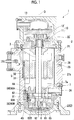
Fig. 1 is a vertical sectional view showing a configuration of a two-stage compressor according to a first embodiment of the present invention. -
Fig. 2 is a perspective view of the two-stage compressor shown inFig. 1 and is a diagram in which a first hanging bolt hole is viewed diagonally from the front. -
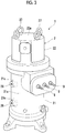
Fig. 3 is a perspective view of the two-stage compressor shown inFig. 1 and is a diagram in which a second hanging bolt hole is viewed diagonally from the front. -
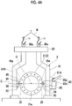
Fig. 4A is a front view showing a state where a housing main body is clamped by a tool and is a diagram showing the housing main body in a posture in which a rotational axis direction is directed in a horizontal direction. -
Fig. 4B is a front view showing a state where the housing main body is clamped by the tool and is a diagram showing the housing main body rotated to a posture in which the rotational axis direction is directed upward. Description of Embodiments - Hereinafter, a compressor and a tool according to an embodiment of the present invention will be described based on the drawings. Such an embodiment is for showing an aspect of the present invention, does not limit the present invention, and can be optionally changed within the scope of the technical idea of the present invention.
- As shown in
Fig. 1 , acompressor 1 according to the present embodiment is a vertical semi-sealed compressor that is used in, for example, an air conditioner, a refrigeration device, or the like. However, the type of thecompressor 1 is not limited to that in the present embodiment. - The
compressor 1 includes ahousing 2, arotary shaft 3, an upper bearing 4A, a lower bearing 4B, anelectric motor 5, arotary compression portion 6, ascroll compression portion 10, and asuction pipe 7. Therotary shaft 3 extends along an axis (a rotational axis O (described later)). The upper bearing 4A and the lower bearing 4B support therotary shaft 3 such that therotary shaft 3 is rotatable around the rotational axis O. Theelectric motor 5 rotates therotary shaft 3. Therotary compression portion 6 compresses a refrigerant with the rotation of therotary shaft 3. Thesuction pipe 7 allows the refrigerant to be introduced intocompression chambers rotary compression portion 6. - The
compressor 1 of the present embodiment is a two-stage compressor that includes both therotary compression portion 6 and thescroll compression portion 10. However, thecompressor 1 may be a single-stage compressor provided with only one of therotary compression portion 6 and thescroll compression portion 10, and thecompressor 1 is not limited to the type in the present embodiment. - Here, the central axis of the
housing 2 and therotary shaft 3 are disposed on a common axis extending in a vertical direction (an up-down direction), and the common axis will be hereinafter referred to as a rotational axis O. Therotary shaft 3 is disposed such that an extending direction thereof is the up-down direction, and is accommodated in thehousing 2 so as to be rotatable around the rotational axis O. - The
housing 2 is formed by using casting or the like and extends in the up-down direction to accommodate therotary shaft 3, thebearings electric motor 5, therotary compression portion 6, and thescroll compression portion 10. Thehousing 2 has amain body portion 21 having a cylindrical shape, and anupper lid portion 22 and alower lid portion 23 that close the upper and lower openings of themain body portion 21. The inside of thehousing 2 is hermetically sealed by theupper lid portion 22 and thelower lid portion 23. Thehousing 2 has anopening portion 24 formed above a cylinder 60 (60A, 60B) at a lower portion of a side wall. Thesuction pipe 7 is fixed to theopening portion 24 in a state where thesuction pipe 7 is inserted into theopening portion 24 with a pipe axis direction directed in the horizontal direction. - Oil is accumulated in a bottom portion of the
housing 2, so that an oil reservoir is formed. The liquid level of the oil reservoir at the time of initial filling of oil is located above therotary compression portion 6. In this way, therotary compression portion 6 is driven in the oil reservoir. - The
upper lid portion 22 is provided with adischarge pipe 13 that penetrates a peripheral wall portion in a thickness direction and communicates with the inside of thehousing 2. Thedischarge pipe 13 discharges the compressed refrigerant to the outside of thehousing 2. - As shown in
Figs. 2 and3 , a plurality of hangingbolts 27 are detachably provided on anupper surface 22a of theupper lid portion 22. Thehousing 2 can be lifted by a crane or the like by using the hangingbolts 27. - A
refrigerant flow path 28, through which the refrigerant compressed in therotary compression portion 6 flows toward thescroll compression portion 10, is provided to extend in the up-down direction inside themain body portion 21. Therefrigerant flow path 28 is a space formed between astator 52 of the electric motor 5 (described later) and the inner peripheral surface of themain body portion 21. As shown inFig. 2 , athick portion 21b is formed on an outerperipheral side surface 21a of themain body portion 21 corresponding to the position where therefrigerant flow path 28 is provided in themain body portion 21. Thethick portion 21b is formed so as to bulge outward in the radial direction from the outerperipheral side surface 21a of themain body portion 21. Thethick portion 21b has a rectangular parallelepiped shape extending with the direction of the rotational axis O as a longitudinal direction. Here, the outerperipheral side surface 21a of themain body portion 21 is a side surface of themain body portion 21 extending in the circumferential direction orbiting around the rotational axis O. A pair of first hanging bolt holes 25 and 25 (mounting portions) are provided at an interval in the up-down direction (the direction of the rotational axis O) on the outer surface of thethick portion 21b. Female screws to which mounting bolts 86 (refer toFig. 4B ) can be screwed are formed in the first hanging bolt holes 25 and 25. Thethick portion 21b is recessed inward in the radial direction at the positions where the first hanging bolt holes 25 and 25 are formed, and is made such that a fixingportion 85 of a clamping portion 82 (described later) is just fitted thereto (refer toFigs. 4A and4B ). - Further, as shown in
Fig. 3 , a pair ofprotrusions housing 2 from the first position where thethick portion 21b is provided, in themain body portion 21. Theprotrusion 21c protrudes outward in the radial direction from the outerperipheral side surface 21a. Theprotrusion 21c has a columnar shape in which the radial direction is a longitudinal direction thereof. A second hanging bolt hole 26 (a mounting portion) is provided in the protruding end face of each of theprotrusions 21c. Female screws, to each of which the mounting bolt 86 (refer toFig. 4B ) can be screwed, are formed in the second hanging bolt holes 26 and 26. - Each of the first hanging bolt holes 25 and each of the second hanging bolt holes 26 are disposed at the same position in the direction of the rotational axis O so as to form a pair.
- As shown in
Fig. 1 , theelectric motor 5 is accommodated in a central portion in the up-down direction of the inside of thehousing 2. Theelectric motor 5 includes arotor 51 and thestator 52. Therotor 51 is fixed to the outer peripheral surface of therotary shaft 3 and is disposed above therotary compression portion 6. Thestator 52 is disposed so as to surround the outer peripheral surface of therotor 51 and is fixed to the inner surface of themain body portion 21 of thehousing 2. - A power supply (not shown) is connected to the
electric motor 5 through aterminal 9. Theelectric motor 5 rotates therotary shaft 3 by the electric power from the power supply. - The
upper bearing 4A and thelower bearing 4B are disposed so as to sandwich therotary compression portion 6 from above and below. Theupper bearing 4A and thelower bearing 4B are formed of, for example, a metal material, and are fixed to thecylinder 60 configuring therotary compression portion 6 by, for example, bolting. - Further, the
upper bearing 4A is fixed to thehousing 2. Therotary shaft 3 is supported by theupper bearing 4A and thelower bearing 4B so as to be rotatable around the rotational axis O. - The
rotary compression portion 6 is disposed at the bottom portion in thehousing 2 below theelectric motor 5 and compresses the refrigerant sucked from thesuction pipe 7. Therotary compression portion 6 includes a pair of disk-shaped cylinders 60 (60A, 60B), aneccentric shaft portion 61 provided integrally with therotary shaft 3 at a position eccentric with respect to therotary shaft 3, and apiston rotor 62 rotating together with theeccentric shaft portion 61. Thepiston rotor 62 performs eccentric rotating motion in thecompression chambers cylinders - A discharge hole (not shown) is provided in the
cylinder 60 of therotary compression portion 6. The refrigerant compressed in therotary compression portion 6 is discharged from the discharge hole toward the internal space having intermediate pressure in thehousing 2, that is, therefrigerant flow path 28. - The
scroll compression portion 10 further compresses the refrigerant from therefrigerant flow path 28. Thescroll compression portion 10 includes aspiral orbiting scroll 11 that orbits with the rotation of therotary shaft 3, and a fixedscroll 12 that meshes with the orbitingscroll 11 from above in the direction of the rotational axis O and is fixed to thehousing 2. The refrigerant compressed in thescroll compression portion 10 is discharged to the outside of thehousing 2 through thedischarge pipe 13. - Next, a
tool 8 that is used when assembling thecompressor 1 described above will be described usingFigs. 4A and4B . - The
tool 8 is a tool for clamping the hanging bolt holes 25 and 26 of thehousing 2 of thecompressor 1 and rotatably supporting thehousing 2. - The
tool 8 includes a pair ofsupport arms 81, the clampingportion 82 detachably provided to each of the hanging bolt holes 25 and 26 provided in themain body portion 21 of thehousing 2, and ahandle portion 83 for rotating the clampingportion 82.Arms main body portion 21 from the radial direction, between them. Further, thearms connection frame 80. A plurality ofsupport portions 80a, to which a hook H and a wire W can be mounted so as to protrude upward on the side opposite to thearms connection frame 80. - The clamping
portions 82 are provided so as to face each other at the pair ofarms portion 82 has a rotatingportion 84 and a fixingportion 85 fixed to the rotatingportion 84. The fixingportion 85 is a long member, and the central portion thereof in the length direction is fixed to the rotatingportion 84. Abolt hole 85a, which penetrates in a direction in which the pair of clampingportions housing 2, is formed in the fixingportion 85. Thehousing 2 can be clamped by thetool 8 by inserting the mountingbolt 86 into thebolt hole 85a and screwing and fastening the mountingbolt 86 to each of the hanging bolt holes 25 and 26. - The
handle portion 83 has apower transmission portion 83a that is supported by thearm 81A on the outside of thearm 81A and rotates the rotatingportion 84, and a handlemain body 83b that gives a rotational force to thepower transmission portion 83a. The handlemain body 83b is rotated, whereby thehousing 2 clamped by the clampingportions 82 is changed to a posture in which thehousing 2 is rotated at a desired rotation angle. - Next, the operation and effects of the compressor and the tool described above will be specifically described based on the drawings.
- In the
compressor 1 according to the present embodiment, as shown inFigs. 2 and3 , for example, thetool 8 as described above is mounted to the firsthanging bolt hole 25 and the secondhanging bolt hole 26 provided in themain body portion 21 of thehousing 2, and then thetool 8 can be lifted by, for example, a crane facility through the wire W and the hook H. At this time, since the hanging bolt holes 25 and 26 are disposed on the outerperipheral side surface 21a of themain body portion 21, as shown inFigs. 4A and4B , themain body portion 21 can be easily changed to a rotated or inverted posture with the axis extending in the direction orthogonal to the rotational axis O, that is, in the radial direction of thehousing 2 as a rotation center C. Therefore, even if thecompressor 1 is large, it is possible to efficiently perform the work of assembling thecompressor 1. - Further, in the present embodiment, the housing 2 (the main body portion 21) can be clamped by using the first hanging bolt holes 25 and the second hanging bolt holes 26 provided in the
thick portion 21b and theprotrusion 21c shifted from each other by 180° in the circumferential direction in themain body portion 21 of the housing 2 (refer toFigs. 4A and4B ). That is, since themain body portion 21 can be supported at positions on both sides with the central axis of themain body portion 21 interposed therebetween, themain body portion 21 can be more reliably and easily rotated or inverted with the clamping position as the center. - Further, in the present embodiment, since it is possible to clamp the
main body portion 21 by using the two mounting portions (the first hanging bolt holes 25 or the second hanging bolt holes 26) disposed at an interval in the direction of the rotational axis O at the clamping positions in the circumferential direction in themain body portion 21, a clamping force can be increased, a sufficient clamping force can be secured, and themain body portion 21 can be rotated or inverted in a stable posture. - Further, in the present embodiment, since the first
hanging bolt hole 25 is provided in thethick portion 21b of themain body portion 21, it is possible to increase the strength of the portion of thehousing 2, where the mounting portion (the firsthanging bolt hole 25 as in the present embodiment) is provided. Therefore, it is possible to more reliably rotate or invert thehousing 2. - Further, in the
tool 8 according to the present embodiment, as shown inFigs. 4A and4B , themain body portion 21 can be clamped by mounting the clampingportions 82 of thetool 8 to the firsthanging bolt hole 25 and the secondhanging bolt hole 26 provided on the outerperipheral side surface 21a of themain body portion 21 of thehousing 2. Then, by rotating thehandle portion 83 of thetool 8, it is possible to easily rotate or invert the clampedmain body portion 21 around the rotation center C. Therefore, even if thecompressor 1 is large, it is possible to efficiently perform the assembly work. - The embodiment related to the
compressor 1 and thetool 8 according to the present invention has been described above. However, the present invention is not limited to the embodiment described above and can be appropriately changed within a scope which does not depart from the gist of the present invention. - For example, in the present embodiment, the configuration is adopted in which the mounting portions (the first
hanging bolt hole 25 and the second hanging bolt hole 26) are provided in thethick portion 21b and theprotrusion 21c shifted from each other by 180° in the circumferential direction in themain body portion 21. However, there is no limitation to these positions. For example, there is no limitation to two locations (the first position and the second position) shifted from each other by 180° in the circumferential direction, and only one position in the circumferential direction may be used. In a case where the mounting portion is provided at only one location in the circumferential direction, a support state by cantilever is created. However, if a reliable supporting force (clamping force) is obtained, thehousing 2 can be clamped at only one location and then rotated or inverted. - Further, the mounting portion is not provided in the
thick portion 21b or theprotrusion 21c and may be directly provided on the outerperipheral side surface 21a of themain body portion 21, for example. - Further, in the present embodiment, the configuration is adopted in which the first hanging bolt holes 25 and the second hanging bolt holes 26 are respectively provided at the two locations at an interval in the direction of the rotational axis O. However, the location may be one or three or more.
- Further, in the present embodiment, the configuration is adopted in which the mounting portions (the first
hanging bolt hole 25 and the second hanging bolt hole 26) are provided in themain body portion 21 of thehousing 2. However, as long as it is the outer peripheral side surface of thehousing 2, it is not limited to the outerperipheral side surface 21a of themain body portion 21. - Furthermore, in the embodiment described above, as the tool which is mounted to the mounting portion, the configuration in which the tool is provided with the
support arm 81 or therotatable handle portion 83 shown inFigs. 4A and4B is shown as an example. However, the tool to be mounted to the mounting portion is not limited to the tool described above. For example, a form may be adopted in which an eyebolt is mounted to the mounting portion and the eyebolt is hung with a wire and lifted by a crane. - Further, the configuration such as the shape or the size of each of the
housing 2, therotary shaft 3, theupper bearing 4A, thelower bearing 4B, theelectric motor 5, the rotary compression portion 6 (thecylinder 60, theeccentric shaft portion 61, the piston rotor 62), the scroll compression portion 10 (the orbitingscroll 11, the fixed scroll 12), and thesuction pipe 7 can be set to an appropriate configuration. For example, in the present embodiment, the twin rotary type compressor having the pair ofcylinders - In addition, it is possible to appropriately replace the components in the embodiment described above with well-known components within the scope which does not depart from the gist of the present invention, and the embodiments described above may be combined appropriately.
- According to the compressor and the tool of the present invention, it is possible to easily change the posture of the housing.
-
- 1:
- compressor
- 2:
- housing
- 3:
- rotary shaft
- 4A:
- upper bearing
- 4B:
- lower bearing
- 5:
- electric motor
- 6:
- rotary compression portion (compression portion)
- 8:
- tool
- 10:
- scroll compression portion (compression portion)
- 11:
- orbiting scroll
- 12:
- fixed scroll
- 21:
- main body portion
- 21a:
- outer peripheral side surface
- 21b:
- thick portion (first position)
- 21c:
- protrusion (second position)
- 25:
- first hanging bolt hole (mounting portion)
- 26:
- second hanging bolt hole (mounting portion)
- 28:
- refrigerant flow path
- 60 (60A, 60B):
- cylinder
- 63A, 63B:
- compression chamber
- 80:
- connection frame
- 80a:
- support portion
- 81 (81A, 81B):
- support arm
- 82:
- clamping portion
- 83:
- handle portion
- 83a:
- power transmission portion
- 83b:
- handle main body
- 84:
- rotating portion
- 85:
- fixing portion
- 86:
- mounting bolt
- W:
- wire
- H:
- hook
- O:
- rotational axis (axis)
- C:
- rotation center
Claims (5)
- A compressor comprising:a rotary shaft extending along an axis;a bearing that supports the rotary shaft such that the rotary shaft is rotatable around the axis;a motor rotating the rotary shaft;a compression portion compressing a refrigerant with rotation of the rotary shaft; anda housing accommodating the rotary shaft, the bearing, the motor, and the compression portion,wherein a mounting portion for hanging the housing is provided on an outer peripheral side surface of the housing.
- The compressor according to claim 1, wherein the mounting portions are provided at a first position and a second position shifted from the first position by 180° in a circumferential direction in the housing.
- The compressor according to claim 1 or 2, wherein a plurality of the mounting portions are provided at intervals in an axis direction of the rotary shaft.
- The compressor according to any one of claims 1 to 3, wherein the mounting portion is provided at a thick portion that bulges outward in a radial direction on the outer peripheral side surface of the housing.
- A tool that clamps the mounting portion of the housing in the compressor according to any one of claims 1 to 4 and rotatably supports the housing, comprising:a clamping portion that is detachably provided to the mounting portion and clamps the mounting portion; anda handle portion that rotates the clamping portion around a rotational axis extending in a direction intersecting a central axis of the housing, in a state where the clamping portion clamps the mounting portion.
Applications Claiming Priority (1)
| Application Number | Priority Date | Filing Date | Title |
|---|---|---|---|
| PCT/JP2019/018801 WO2020230207A1 (en) | 2019-05-10 | 2019-05-10 | Compressor and tool |
Publications (4)
| Publication Number | Publication Date |
|---|---|
| EP3936721A1 true EP3936721A1 (en) | 2022-01-12 |
| EP3936721A4 EP3936721A4 (en) | 2022-03-16 |
| EP3936721B1 EP3936721B1 (en) | 2026-01-28 |
| EP3936721C0 EP3936721C0 (en) | 2026-01-28 |
Family
ID=73289507
Family Applications (1)
| Application Number | Title | Priority Date | Filing Date |
|---|---|---|---|
| EP19928733.5A Active EP3936721B1 (en) | 2019-05-10 | 2019-05-10 | Compressor and tool |
Country Status (3)
| Country | Link |
|---|---|
| EP (1) | EP3936721B1 (en) |
| JP (1) | JP7372967B2 (en) |
| WO (1) | WO2020230207A1 (en) |
Family Cites Families (6)
| Publication number | Priority date | Publication date | Assignee | Title |
|---|---|---|---|---|
| JP2012077658A (en) * | 2010-09-30 | 2012-04-19 | Fujitsu General Ltd | Refrigerant compressor |
| JP6020148B2 (en) * | 2012-03-20 | 2016-11-02 | 株式会社豊田自動織機 | Electric compressor |
| JP5516651B2 (en) * | 2012-06-14 | 2014-06-11 | ダイキン工業株式会社 | Scroll compressor |
| JP2018016876A (en) * | 2016-07-29 | 2018-02-01 | ダイキン工業株式会社 | Compressor, and compressor manufacturing method |
| JP6270080B1 (en) | 2016-10-19 | 2018-01-31 | 三菱重工サーマルシステムズ株式会社 | Hermetic rotary compressor |
| JP6760148B2 (en) * | 2017-03-10 | 2020-09-23 | 株式会社豊田自動織機 | Electric compressor for vehicles |
-
2019
- 2019-05-10 JP JP2021519050A patent/JP7372967B2/en active Active
- 2019-05-10 EP EP19928733.5A patent/EP3936721B1/en active Active
- 2019-05-10 WO PCT/JP2019/018801 patent/WO2020230207A1/en not_active Ceased
Also Published As
| Publication number | Publication date |
|---|---|
| JP7372967B2 (en) | 2023-11-01 |
| JPWO2020230207A1 (en) | 2020-11-19 |
| EP3936721B1 (en) | 2026-01-28 |
| EP3936721A4 (en) | 2022-03-16 |
| EP3936721C0 (en) | 2026-01-28 |
| WO2020230207A1 (en) | 2020-11-19 |
Similar Documents
| Publication | Publication Date | Title |
|---|---|---|
| JP5109642B2 (en) | Electric compressor | |
| JP5018450B2 (en) | Electric compressor | |
| EP1471257B1 (en) | Multi-cylinder rotary compressor | |
| EP3951181B1 (en) | Rotary compressor | |
| JP4826212B2 (en) | Electric compressor | |
| US20160135320A1 (en) | Circuit assembly with vibration-proof circuit component fixing structure, and vehicular electric compressor | |
| CN103459849B (en) | Scroll compression device | |
| US6773244B2 (en) | Discharging part structure for compressor | |
| EP3754270A1 (en) | Accumulator, and compressor for air conditioning | |
| EP3936721B1 (en) | Compressor and tool | |
| CN101326368B (en) | Compressor | |
| JP6416645B2 (en) | Hermetic compressor | |
| JP2013177827A (en) | Electric compressor | |
| WO2018168345A1 (en) | Rotary compressor | |
| KR100339583B1 (en) | Structure for engaging gap gauge in compressor | |
| JP2005220762A (en) | Compressor | |
| KR20180111521A (en) | Electric compressor | |
| KR100447207B1 (en) | Scroll compressor with outer rotor type motor | |
| KR20250132383A (en) | Electric compressor | |
| JP2014202117A (en) | Compressor | |
| JPH08109885A (en) | Assembly method and assembly jig for scroll compressor | |
| KR100447205B1 (en) | Scroll compressor with outer rotor type motor | |
| EP3409944A1 (en) | Hermetic compressor and method of producing hermetic compressor | |
| KR20050062986A (en) | Apparatus for fixed the axis of rotation in a rotary compressor | |
| KR20030097337A (en) | Structure for assembling a cylinder of compressor |
Legal Events
| Date | Code | Title | Description |
|---|---|---|---|
| STAA | Information on the status of an ep patent application or granted ep patent |
Free format text: STATUS: THE INTERNATIONAL PUBLICATION HAS BEEN MADE |
|
| PUAI | Public reference made under article 153(3) epc to a published international application that has entered the european phase |
Free format text: ORIGINAL CODE: 0009012 |
|
| STAA | Information on the status of an ep patent application or granted ep patent |
Free format text: STATUS: REQUEST FOR EXAMINATION WAS MADE |
|
| 17P | Request for examination filed |
Effective date: 20211008 |
|
| AK | Designated contracting states |
Kind code of ref document: A1 Designated state(s): AL AT BE BG CH CY CZ DE DK EE ES FI FR GB GR HR HU IE IS IT LI LT LU LV MC MK MT NL NO PL PT RO RS SE SI SK SM TR |
|
| A4 | Supplementary search report drawn up and despatched |
Effective date: 20220216 |
|
| RIC1 | Information provided on ipc code assigned before grant |
Ipc: F04C 23/00 20060101ALI20220210BHEP Ipc: F01C 21/10 20060101ALI20220210BHEP Ipc: F04C 29/00 20060101ALI20220210BHEP Ipc: F04B 41/00 20060101ALI20220210BHEP Ipc: F04B 39/14 20060101ALI20220210BHEP Ipc: F04B 39/12 20060101AFI20220210BHEP |
|
| DAV | Request for validation of the european patent (deleted) | ||
| DAX | Request for extension of the european patent (deleted) | ||
| STAA | Information on the status of an ep patent application or granted ep patent |
Free format text: STATUS: EXAMINATION IS IN PROGRESS |
|
| 17Q | First examination report despatched |
Effective date: 20231212 |
|
| GRAP | Despatch of communication of intention to grant a patent |
Free format text: ORIGINAL CODE: EPIDOSNIGR1 |
|
| STAA | Information on the status of an ep patent application or granted ep patent |
Free format text: STATUS: GRANT OF PATENT IS INTENDED |
|
| INTG | Intention to grant announced |
Effective date: 20250902 |
|
| GRAS | Grant fee paid |
Free format text: ORIGINAL CODE: EPIDOSNIGR3 |
|
| GRAA | (expected) grant |
Free format text: ORIGINAL CODE: 0009210 |
|
| STAA | Information on the status of an ep patent application or granted ep patent |
Free format text: STATUS: THE PATENT HAS BEEN GRANTED |
|
| AK | Designated contracting states |
Kind code of ref document: B1 Designated state(s): AL AT BE BG CH CY CZ DE DK EE ES FI FR GB GR HR HU IE IS IT LI LT LU LV MC MK MT NL NO PL PT RO RS SE SI SK SM TR |
|
| REG | Reference to a national code |
Ref country code: CH Ref legal event code: F10 Free format text: ST27 STATUS EVENT CODE: U-0-0-F10-F00 (AS PROVIDED BY THE NATIONAL OFFICE) Effective date: 20260128 Ref country code: GB Ref legal event code: FG4D |
|
| REG | Reference to a national code |
Ref country code: DE Ref legal event code: R096 Ref document number: 602019081017 Country of ref document: DE |
|
| REG | Reference to a national code |
Ref country code: IE Ref legal event code: FG4D |
|
| U01 | Request for unitary effect filed |
Effective date: 20260225 |
|
| U07 | Unitary effect registered |
Designated state(s): AT BE BG DE DK EE FI FR IT LT LU LV MT NL PT RO SE SI Effective date: 20260302 |
|
| U20 | Renewal fee for the european patent with unitary effect paid |
Year of fee payment: 8 Effective date: 20260423 |
|
| PG25 | Lapsed in a contracting state [announced via postgrant information from national office to epo] |
Ref country code: RS Free format text: LAPSE BECAUSE OF FAILURE TO SUBMIT A TRANSLATION OF THE DESCRIPTION OR TO PAY THE FEE WITHIN THE PRESCRIBED TIME-LIMIT Effective date: 20260428 |
|
| PG25 | Lapsed in a contracting state [announced via postgrant information from national office to epo] |
Ref country code: ES Free format text: LAPSE BECAUSE OF FAILURE TO SUBMIT A TRANSLATION OF THE DESCRIPTION OR TO PAY THE FEE WITHIN THE PRESCRIBED TIME-LIMIT Effective date: 20260128 |
|
| PG25 | Lapsed in a contracting state [announced via postgrant information from national office to epo] |
Ref country code: PL Free format text: LAPSE BECAUSE OF FAILURE TO SUBMIT A TRANSLATION OF THE DESCRIPTION OR TO PAY THE FEE WITHIN THE PRESCRIBED TIME-LIMIT Effective date: 20260128 |
|
| PGFP | Annual fee paid to national office [announced via postgrant information from national office to epo] |
Ref country code: GB Payment date: 20260518 Year of fee payment: 8 |
|
| PG25 | Lapsed in a contracting state [announced via postgrant information from national office to epo] |
Ref country code: GR Free format text: LAPSE BECAUSE OF FAILURE TO SUBMIT A TRANSLATION OF THE DESCRIPTION OR TO PAY THE FEE WITHIN THE PRESCRIBED TIME-LIMIT Effective date: 20260429 |
|
| PG25 | Lapsed in a contracting state [announced via postgrant information from national office to epo] |
Ref country code: NO Free format text: LAPSE BECAUSE OF FAILURE TO SUBMIT A TRANSLATION OF THE DESCRIPTION OR TO PAY THE FEE WITHIN THE PRESCRIBED TIME-LIMIT Effective date: 20260428 |
|
| PG25 | Lapsed in a contracting state [announced via postgrant information from national office to epo] |
Ref country code: HR Free format text: LAPSE BECAUSE OF FAILURE TO SUBMIT A TRANSLATION OF THE DESCRIPTION OR TO PAY THE FEE WITHIN THE PRESCRIBED TIME-LIMIT Effective date: 20260128 |
|
| PG25 | Lapsed in a contracting state [announced via postgrant information from national office to epo] |
Ref country code: IS Free format text: LAPSE BECAUSE OF FAILURE TO SUBMIT A TRANSLATION OF THE DESCRIPTION OR TO PAY THE FEE WITHIN THE PRESCRIBED TIME-LIMIT Effective date: 20260528 |