EP3936708A1 - Befestigungsanordnung - Google Patents
Befestigungsanordnung Download PDFInfo
- Publication number
- EP3936708A1 EP3936708A1 EP21184152.3A EP21184152A EP3936708A1 EP 3936708 A1 EP3936708 A1 EP 3936708A1 EP 21184152 A EP21184152 A EP 21184152A EP 3936708 A1 EP3936708 A1 EP 3936708A1
- Authority
- EP
- European Patent Office
- Prior art keywords
- sleeve
- fastening arrangement
- arrangement according
- heat protection
- exhaust manifold
- Prior art date
- Legal status (The legal status is an assumption and is not a legal conclusion. Google has not performed a legal analysis and makes no representation as to the accuracy of the status listed.)
- Granted
Links
Images

Classifications
-
- F—MECHANICAL ENGINEERING; LIGHTING; HEATING; WEAPONS; BLASTING
- F01—MACHINES OR ENGINES IN GENERAL; ENGINE PLANTS IN GENERAL; STEAM ENGINES
- F01N—GAS-FLOW SILENCERS OR EXHAUST APPARATUS FOR MACHINES OR ENGINES IN GENERAL; GAS-FLOW SILENCERS OR EXHAUST APPARATUS FOR INTERNAL-COMBUSTION ENGINES
- F01N13/00—Exhaust or silencing apparatus characterised by constructional features
- F01N13/08—Other arrangements or adaptations of exhaust conduits
- F01N13/10—Other arrangements or adaptations of exhaust conduits of exhaust manifolds
-
- F—MECHANICAL ENGINEERING; LIGHTING; HEATING; WEAPONS; BLASTING
- F01—MACHINES OR ENGINES IN GENERAL; ENGINE PLANTS IN GENERAL; STEAM ENGINES
- F01N—GAS-FLOW SILENCERS OR EXHAUST APPARATUS FOR MACHINES OR ENGINES IN GENERAL; GAS-FLOW SILENCERS OR EXHAUST APPARATUS FOR INTERNAL-COMBUSTION ENGINES
- F01N13/00—Exhaust or silencing apparatus characterised by constructional features
- F01N13/08—Other arrangements or adaptations of exhaust conduits
- F01N13/10—Other arrangements or adaptations of exhaust conduits of exhaust manifolds
- F01N13/102—Other arrangements or adaptations of exhaust conduits of exhaust manifolds having thermal insulation
-
- F—MECHANICAL ENGINEERING; LIGHTING; HEATING; WEAPONS; BLASTING
- F01—MACHINES OR ENGINES IN GENERAL; ENGINE PLANTS IN GENERAL; STEAM ENGINES
- F01N—GAS-FLOW SILENCERS OR EXHAUST APPARATUS FOR MACHINES OR ENGINES IN GENERAL; GAS-FLOW SILENCERS OR EXHAUST APPARATUS FOR INTERNAL-COMBUSTION ENGINES
- F01N13/00—Exhaust or silencing apparatus characterised by constructional features
- F01N13/18—Construction facilitating manufacture, assembly, or disassembly
- F01N13/1838—Construction facilitating manufacture, assembly, or disassembly characterised by the type of connection between parts of exhaust or silencing apparatus, e.g. between housing and tubes, between tubes and baffles
- F01N13/1844—Mechanical joints
- F01N13/1855—Mechanical joints the connection being realised by using bolts, screws, rivets or the like
-
- F—MECHANICAL ENGINEERING; LIGHTING; HEATING; WEAPONS; BLASTING
- F02—COMBUSTION ENGINES; HOT-GAS OR COMBUSTION-PRODUCT ENGINE PLANTS
- F02M—SUPPLYING COMBUSTION ENGINES IN GENERAL WITH COMBUSTIBLE MIXTURES OR CONSTITUENTS THEREOF
- F02M26/00—Engine-pertinent apparatus for adding exhaust gases to combustion-air, main fuel or fuel-air mixture, e.g. by exhaust gas recirculation [EGR] systems
- F02M26/13—Arrangement or layout of EGR passages, e.g. in relation to specific engine parts or for incorporation of accessories
- F02M26/14—Arrangement or layout of EGR passages, e.g. in relation to specific engine parts or for incorporation of accessories in relation to the exhaust system
- F02M26/16—Arrangement or layout of EGR passages, e.g. in relation to specific engine parts or for incorporation of accessories in relation to the exhaust system with EGR valves located at or near the connection to the exhaust system
-
- F—MECHANICAL ENGINEERING; LIGHTING; HEATING; WEAPONS; BLASTING
- F02—COMBUSTION ENGINES; HOT-GAS OR COMBUSTION-PRODUCT ENGINE PLANTS
- F02M—SUPPLYING COMBUSTION ENGINES IN GENERAL WITH COMBUSTIBLE MIXTURES OR CONSTITUENTS THEREOF
- F02M26/00—Engine-pertinent apparatus for adding exhaust gases to combustion-air, main fuel or fuel-air mixture, e.g. by exhaust gas recirculation [EGR] systems
- F02M26/13—Arrangement or layout of EGR passages, e.g. in relation to specific engine parts or for incorporation of accessories
- F02M26/42—Arrangement or layout of EGR passages, e.g. in relation to specific engine parts or for incorporation of accessories having two or more EGR passages; EGR systems specially adapted for engines having two or more cylinders
- F02M26/43—Arrangement or layout of EGR passages, e.g. in relation to specific engine parts or for incorporation of accessories having two or more EGR passages; EGR systems specially adapted for engines having two or more cylinders in which exhaust from only one cylinder or only a group of cylinders is directed to the intake of the engine
-
- F—MECHANICAL ENGINEERING; LIGHTING; HEATING; WEAPONS; BLASTING
- F01—MACHINES OR ENGINES IN GENERAL; ENGINE PLANTS IN GENERAL; STEAM ENGINES
- F01N—GAS-FLOW SILENCERS OR EXHAUST APPARATUS FOR MACHINES OR ENGINES IN GENERAL; GAS-FLOW SILENCERS OR EXHAUST APPARATUS FOR INTERNAL-COMBUSTION ENGINES
- F01N2260/00—Exhaust treating devices having provisions not otherwise provided for
- F01N2260/20—Exhaust treating devices having provisions not otherwise provided for for heat or sound protection, e.g. using a shield or specially shaped outer surface of exhaust device
Definitions
- the invention relates to a fastening arrangement with an engine block, an exhaust manifold, and a connecting flange element, which is fastened to the engine block via a flange surface on the engine side and is fastened to the exhaust manifold via a flange surface on the exhaust manifold side, the connecting flange element having a plurality of passage openings, which extend from the flange surface on the engine side to the extend exhaust manifold side flange and each limit an exhaust channel radially.
- Such a mounting arrangement is, for example, from DE 10 2011 050 517 A1 known.
- the mounting arrangement has an engine block, a connection flange element and an exhaust manifold, the engine block being connected to the exhaust manifold via the connection flange element.
- the connecting flange element has an engine-side flange surface and an exhaust manifold-side flange surface, the exhaust manifold being bolted to the exhaust manifold-side flange surface and the engine block being bolted to the engine-side flange surface.
- the connecting flange element has a plurality of exhaust gas ducts, which extend from the engine-side flange surface to the exhaust manifold-side flange surface, with the exhaust gas ejected from the cylinders flowing into the exhaust manifold via a plurality of exhaust gas paths formed in the engine block, in particular in the cylinder head, and through openings provided on the connecting flange element.
- the individual exhaust gas paths are combined into a single exhaust gas path Combined exhaust gas path flows through exhaust gas aftertreatment components into the environment.
- a disadvantage of such a fastening arrangement is that the connecting flange element must be made of a cost-intensive and thermally highly resilient material, so that the thermal load limit of the connecting flange element can be prevented from being exceeded and failure of the connecting flange element due to thermal overload can be avoided.
- the object is therefore to create a fastening arrangement in which thermal failure of the connection flange element can be prevented in a simple and cost-effective manner.
- a heat protection sleeve is arranged in at least one passage opening and extends axially from the engine-side flange surface to the exhaust-gas manifold-side flange surface reduces the heat transfer between the hot exhaust gas flowing out of a cylinder and the connecting flange element and thus the risk of thermal failure of the connecting flange element is reduced.
- the heat protection sleeve extends from the engine-side flange surface to the exhaust manifold-side flange surface, so that the heat protection sleeve bears against the engine block and the exhaust manifold at the front and is therefore also thermally connected to the engine block and the exhaust manifold.
- connection flange element A thermal failure of the connection flange element can thus be prevented reliably and in a simple and cost-effective manner by the heat protection sleeve.
- the heat protection sleeve is preferably arranged with its outer peripheral surface at a radial distance from a peripheral surface of the passage opening, with the heat protection sleeve delimiting an air gap with the peripheral surface of the passage opening.
- the air gap is delimited radially by the outer peripheral surface of the heat protection sleeve and the peripheral surface of the passage opening and is used for thermal insulation between the exhaust gas duct and the connecting flange element.
- the air gap is separated in a fluid-tight manner from the exhaust gas duct, which is radially delimited by the inner peripheral surface of the heat protection sleeve.
- the air gap reduces the heat transfer between the exhaust gas and the connecting flange element in a simple and cost-effective manner.
- the heat protection sleeve is made from sheet steel.
- the heat protection sleeve can be made from a cost-effective and thermally highly resilient material.
- the connecting flange element preferably has at least one coolant channel through which a coolant flows.
- the connection flange element is additionally cooled by the coolant, which increases the risk of failure of the connection flange element overheating can be further reduced.
- the coolant channel surrounds the passage opening radially.
- the heat protection sleeve preferably has a first sleeve element and a second sleeve element, the first sleeve element extending from the engine-side flange surface and the second sleeve element extending from the exhaust manifold-side flange surface, and the two sleeve elements overlapping with their ends facing one another.
- the heat protection sleeve can be installed easily, with leakage of the exhaust gas into the air gap being reliably prevented by the overlapping of the sleeve elements.
- one of the two sleeve elements is inserted into the other sleeve element.
- One of the two sleeve elements preferably has a radial widening at the end facing the other sleeve element, with the end of the other sleeve element being inserted into the widening.
- the inserted sleeve element is arranged in front of the other sleeve element in the flow direction of the exhaust gas. This reliably prevents the exhaust gas from leaking into the air gap, in that the exhaust gas can be prevented from flowing axially into the contact region between the two sleeve elements.
- the heat protection sleeve preferably has a radially extending collar on at least one of the two axial ends, which collar bears against one of the two flange surfaces. This allows the sleeve simply by the Installation of the flange element can be fixed to the engine block or the exhaust manifold by clamping the heat protection sleeve between the flange element and the engine block or the exhaust manifold.
- the flange surface has a shoulder in which the collar of the heat protection sleeve is arranged.
- the heat protection sleeve can be positioned radially, with the engine block or the exhaust manifold bearing against the connecting flange element over its entire surface, despite the collar of the heat protection sleeve being arranged on the flange surface.
- the collar that extends radially preferably has a bead that rests axially on the connection flange element, as a result of which a leakage flow between the flange surface and the collar, in particular into the air gap, is reduced.
- the heat protection sleeve is crimped to the connecting flange element at least at one of the two axial ends.
- a chamfer is preferably provided on an axial end of an inner surface of the passage opening and the heat protection sleeve is bent radially outwards at the axial end.
- connection flange element A fastening arrangement is thus created in which a thermal overload of the connection flange element is prevented in a simple manner.
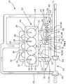
- the figure 1 shows an exhaust system 10 for an internal combustion engine 12 of a motor vehicle.
- the internal combustion engine 12 has an engine block 14 which has four cylinders 16 , 18 , 20 , 22 .
- the cylinders 16, 18, 20, 22 each have an air inlet 24, 26, 28, 30 through which air for the combustion processes in the cylinders 16, 18, 20, 22 can be supplied.
- the air inlets 24, 26, 28, 30 are connected to an air inlet manifold 32, which is connected to an air inlet duct 33, air being supplied to the air inlet manifold 32 via the air inlet duct 33 and the air being fed through the air inlet manifold 32 to the air inlets 24, 26, 28 , 30 is divided.
- a fuel injector 34, 36, 38, 40 is provided for each cylinder 16, 18, 20, 22, through which fuel can be supplied to the respective cylinders 16, 18, 20, 22 as required.
- the cylinders 16, 18, 20, 22 each have an exhaust gas outlet 42, 44, 46, 48 for the exhaust of the exhaust gases produced during the combustion process.
- Each exhaust outlet 42, 44, 46, 48 is fluidically connected to an exhaust line 50, 52, 54, 56 extending through the engine block 14, the exhaust lines 52, 54 associated with the second and third cylinders 18, 20 being combined.
- an exhaust gas recirculation line 60 is branched off from the exhaust gas line 56 assigned to a fourth cylinder 22 .
- the exhaust gas recirculation line 60 is fluidically connected to the air intake port 33 so that at least part of the exhaust gas flowing out of the fourth cylinder 22 can be supplied to the air intake port 33 .
- only the exhaust gas discharged from the fourth cylinder 22 is used for exhaust gas recirculation to reduce pollutants.
- the exhaust gas flowing out of the cylinders 16, 18, 20, 22 is also used to compress the air flowing through the air intake duct 33, the exhaust gas from the cylinders 16, 18, 20, 22 being fed to a turbine 64 of a turbocharger 62.
- the turbine 64 is non-rotatably connected to a compressor 66 of the turbocharger 62 such that the compressor 66 is driven by the turbine 64 and compresses the air required for the combustion process.
- an exhaust manifold 70 is provided, in which all exhaust gas lines 50, 52, 54, 56 open, with the exhaust manifold 70 combining all exhaust gas mass flows and a single exhaust gas mass flow the turbine 64 is supplied.
- the connection between the exhaust manifold 70 and the engine block 14 is via a flange element 72, wherein the engine block 14, the exhaust manifold 70 and the flange element 72 together a Fastening arrangement 71 form.
- the connecting flange element 72 is made of aluminum and has a flat flange surface 74 on the engine side and a flat flange surface 76 on the exhaust manifold side.
- the engine block 14 is fastened to the flange surface 74 on the engine side.
- the exhaust manifold 70 is fastened to the flange surface 76 on the exhaust manifold side.
- the connecting flange element 72 comprises four passage openings 77, 79, 83, 85, each of which delimits an exhaust gas duct 78, 80, 84, 86 and whose longitudinal axes run parallel to one another, with all passage openings 77, 79, 83, 85 extending from the engine-side flange surface 74 to extend to the flange surface 76 on the exhaust manifold side.
- a first exhaust gas duct 78 is assigned to the exhaust gas line 50 assigned to the first cylinder 16 .
- a second exhaust gas duct 80 is assigned to the combined exhaust gas lines 52, 54 of the two cylinders 18, 20.
- a third exhaust gas duct 84 and the fourth exhaust gas duct 86 are associated with the exhaust line 56 assigned to the fourth cylinder 22, with the exhaust gas line 56 being connected to the exhaust manifold 70 via the third exhaust gas duct 84 and the exhaust gas line 56 being connected to the exhaust gas recirculation line 60 via the fourth exhaust gas duct 86 .
- the fluidic connection of the exhaust line 56 associated with the fourth cylinder 22 to the exhaust manifold 70 or to the exhaust gas recirculation line 60 is controlled by a flap device 90 .
- the flap device 90 includes an actuator 92 which drives a flap shaft 94 .
- Two flaps 96 , 98 are fastened to the flap shaft 94 , with a first flap 96 being arranged in the third exhaust gas duct 84 and the second flap 98 being arranged in the fourth exhaust gas duct 86 .
- the two flaps 96, 98 are arranged in the exhaust gas ducts 84, 86 in such a way that either the third exhaust gas duct 84 or the fourth exhaust gas duct 86 is open and thus, when one of the two flaps 96, 98 is in the open position, the other flap 96, 98 opens the corresponding exhaust gas duct 84 , 86 closed.
- exhaust gas recirculation can be enabled or prevented, with exhaust gas being able to flow exclusively into exhaust gas recirculation line 60 when exhaust gas recirculation is enabled. Otherwise no exhaust gas can flow into the exhaust gas recirculation line 60 and the exhaust gas flows completely to the turbocharger 62.
- the connecting flange element 72 Because the hot exhaust gas flows through the connecting flange element 72 , the connecting flange element 72 is exposed to a high thermal load.
- a heat protection sleeve 110, 112 is arranged in the first passage opening 77 and in the second passage opening 79 in order to avoid thermal overloading of the connecting flange element 72, with the heat protection sleeves 110, 112 extending axially from the engine-side flange surface 74 to the exhaust manifold-side flange surface 76 extend.
- figure 3 is a section through the area of the first passage opening 77 and in figure 4 a section through the area of the second passage opening 79 is shown.
- a gap 118, 120 is provided between an outer peripheral surface of the heat protection sleeve 110, 112 and the peripheral surfaces 114, 116 of the passage openings 77, 79, creating an air gap insulation.
- the heat protection sleeve 110 is in two parts and made of sheet steel, the heat protection sleeve 110 having a first sleeve element 122 and a second sleeve element 124 .
- the first sleeve element 122 extends from the motor-side flange surface 74 and protrudes into the first through-opening 77 thereto corresponding shoulder 128 is arranged on the motor-side flange surface 74, so that the collar 126 is level with the motor-side flange surface 74 and does not protrude axially.
- a sealing bead 127 is also provided on the collar 126 .
- the second sleeve element 124 extends from the flange surface 76 on the exhaust manifold side and also has a radially extending collar 130 which is arranged in a shoulder 132 provided on the flange surface 76 on the exhaust manifold side and has a sealing bead 131 .
- the sealing beads 127, 131 serve to ensure that the collars 126, 130 rest against the connecting flange element 72 in the area of the shoulders 128, 132 and thus ensure the tightness in this area.
- the second sleeve element 124 has a widening 134 at its axial end facing the first sleeve element 122, the first sleeve element 122 being inserted into the second sleeve element 124 in the region of the widening.
- the heat protection sleeve 112 is in one piece and made of sheet steel. At a first axial end, the heat protection sleeve 112 has a radially extending and circumferential collar 140 which is arranged in a shoulder 142 provided on the flange surface 76 on the exhaust manifold side. At its opposite axial end, the heat protection sleeve 112 is bent open after the heat protection sleeve 112 has been inserted into the second passage opening 79 and is thus crimped to the connection flange element 72 .
- a chamfer 144 is provided on the peripheral surface 116 of the second passage opening 79, with the heat protection sleeve 112 resting against the connecting flange element 72 with the bent section in the region of the chamfer 144 after the crimping.
- coolant channels 100 are also provided in the connection flange element 72, with such a coolant channel 100 in the Figures 3 and 4 is shown.
- the coolant channel 100 surrounds the respective exhaust gas channel 78, 80, 84, 86 radially.
- the heat transferred from the exhaust gas to the connecting element 72 is at least partially dissipated through the coolant channels 100 .
Landscapes
- Engineering & Computer Science (AREA)
- Chemical & Material Sciences (AREA)
- Combustion & Propulsion (AREA)
- Mechanical Engineering (AREA)
- General Engineering & Computer Science (AREA)
- Exhaust Silencers (AREA)
Abstract
Description
- Die Erfindung betrifft eine Befestigungsanordnung mit einem Motorblock, einem Abgaskrümmer, und einem Anschlussflanschelement, welches über eine motorseitige Flanschfläche am Motorblock befestigt ist und über eine abgaskrümmerseitige Flanschfläche am Abgaskrümmer befestigt ist, wobei das Anschlussflanschelement mehrere Durchtrittsöffnungen aufweist, welche sich von der motorseitigen Flanschfläche bis zur abgaskrümmerseitigen Flanschfläche erstrecken und jeweils einen Abgaskanal radial begrenzen.
- Eine derartige Befestigungsanordnung ist beispielsweise aus der
DE 10 2011 050 517 A1 bekannt. Die Befestigungsanordnung weist einen Motorblock, ein Anschlussflanschelement und einen Abgaskrümmer auf, wobei der Motorblock über das Anschlussflanschelement mit dem Abgaskrümmer verbunden ist. Das Anschlussflanschelement weist eine motorseitige Flanschfläche und eine abgaskrümmerseitige Flanschfläche auf, wobei der Abgaskrümmer an der abgaskrümmerseitigen Flanschfläche verschraubt ist und der Motorblock an der motorseitigen Flanschfläche verschraubt ist. Das Anschlussflanschelement weist mehrere Abgaskanäle auf, welche sich von der motorseitigen Flanschfläche zur abgaskrümmerseitigen Flanschfläche erstrecken, wobei das aus den Zylindern ausgestoßene Abgas über mehrere im Motorblock, insbesondere im Zylinderkopf, ausgebildete Abgaspfade und über am Anschlussflanschelement vorgesehene Durchtrittsöffnungen in den Abgaskrümmer strömt. Im Abgaskrümmer werden die einzelnen Abgaspfade zu einem einzigen Abgaspfad zusammengefasst, wobei der zusammengefasste Abgaspfad unter Durchströmung von Abgasnachbehandlungskomponenten in die Umgebung strömt. - Nachteilhaft an einer derartigen Befestigungsanordnung ist, dass das Anschlussflanschelement aus einem kostenintensiven und thermisch hoch belastbaren Material hergestellt werden muss, damit eine Überschreitung der thermischen Belastungsgrenze des Anschlussflanschelements verhindert werden kann und ein Ausfall des Anschlussflanschelements aufgrund von einer thermischen Überlastung vermieden werden kann.
- Es stellt sich somit die Aufgabe, eine Befestigungsanordnung zu schaffen, bei welcher ein thermisches Versagen des Anschlussflanschelements auf einfache und kostengünstige Weise verhindert werden kann.
- Diese Aufgabe wird durch eine Befestigungsanordnung mit den Merkmalen des Hauptanspruchs 1 gelöst.
- Dadurch, dass in zumindest einer Durchtrittsöffnung eine Hitzeschutz-Hülse angeordnet ist, welche sich axial von der motorseitigen Flanschfläche bis zur abgaskrümmerseitigen Flanschfläche erstreckt, wird die Wärmeübertragung zwischen dem von einem Zylinder abströmenden, heißen Abgas und dem Anschlussflanschelement reduziert und dadurch die Gefahr eines thermischen Versagens des Anschlussflanschelements reduziert. Die Hitzeschutz-Hülse erstreckt sich von der motorseitigen Flanschfläche zur abgaskrümmerseitigen Flanschfläche, so dass die Hitzeschutz-Hülse an dem Motorblock und an dem Abgaskrümmer stirnseitig anliegt und dadurch auch thermisch mit dem Motorblock und dem Abgaskrümmer verbunden ist. Durch die Hitzeschutz-Hülse erfolgt damit lediglich ein mittelbarer Wärmeübergang zwischen dem heißen Abgas und dem Anschlussflanschelement, wobei bereits durch die Hitzeschutz-Hülse ein Teil der Wärme, insbesondere über die beiden Flanschflächen an den Abgaskrümmer und den Motorblock, abgeführt wird.
- Damit kann durch die Hitzeschutz-Hülse ein thermisches Versagen des Anschlussflanschelements zuverlässig und auf eine einfache und kostengünstige Weise verhindert werden.
- Vorzugsweise ist die Hitzeschutz-Hülse mit ihrer Außenumfangsfläche radial beabstandet von einer Umfangsfläche der Durchtrittsöffnung angeordnet, wobei die Hitzeschutz-Hülse mit der Umfangsfläche der Durchtrittsöffnung ein Luftspalt begrenzt. Der Luftspalt wird von der Außenumfangsfläche der Hitzeschutz-Hülse sowie der Umfangsfläche der Durchtrittsöffnung radial begrenzt und dient der thermischen Isolierung zwischen dem Abgaskanal und dem Anschlussflanschelement. Der Luftspalt ist fluiddicht von dem durch die Innenumfangsfläche der Hitzeschutz-Hülse radial begrenzten Abgaskanal getrennt.
- Durch den Luftspalt wird auf eine einfache und kostengünstige Weise die Wärmeübertragung zwischen dem Abgas und dem Anschlussflanschelement reduziert.
- In einer bevorzugten Ausgestaltung ist die Hitzeschutz-Hülse aus einem Stahlblech hergestellt. Dadurch kann die Hitzeschutz-Hülse aus einem kostengünstigen und thermisch hochbelastbaren Material ausgeführt werden.
- Vorzugsweise weist das Anschlussflanschelement mindestens ein Kühlmittelkanal auf, welcher von einem Kühlmittel durchströmt ist. Das Anschlussflanschelement wird durch das Kühlmittel zusätzlich gekühlt, wodurch die Gefahr eines Ausfalls des Anschlussflanschelements aufgrund einer Überhitzung nochmals reduziert werden kann. In einer bevorzugten Ausgestaltung umgibt der Kühlmittelkanal die Durchtrittsöffnung radial.
- Vorzugsweise weist die Hitzeschutz-Hülse ein erstes Hülsenelement und ein zweites Hülsenelement auf, wobei sich das erste Hülsenelement von der motorseitigen Flanschfläche erstreckt und das zweite Hülsenelement sich von der abgaskrümmerseitigen Flanschfläche erstreckt, und wobei sich die beiden Hülsenelemente mit ihren zueinander zugewandten Enden überlappen. Dadurch kann die Hitzeschutz-Hülse einfach montiert werden, wobei durch die Überlappung der Hülsenelemente eine Leckage des Abgases in den Luftspalt zuverlässig verhindert wird.
- In einer bevorzugten Ausgestaltung ist eines der beiden Hülsenelemente in das andere Hülsenelement eingesteckt. Vorzugsweise weist eines der beiden Hülsenelemente an dem dem anderen Hülsenelement zugewandten Ende eine radiale Aufweitung auf, wobei in die Aufweitung das Ende des anderen Hülsenelements eingesteckt ist. Dadurch können die beiden Hülsenelemente auf eine einfache und kostengünstige Weise miteinander montiert werden und eine Leckage des Abgases in den Luftspalt zuverlässig verhindert werden.
- In einer bevorzugten Ausgestaltung ist das eingesteckte Hülsenelement in Strömungsrichtung des Abgases vor dem anderen Hülsenelement angeordnet. Dadurch wird eine Leckage des Abgases in den Luftspalt zuverlässig verhindert, indem ein axiales Einströmen des Abgases in den Kontaktbereich zwischen den beiden Hülsenelementen verhindert werden kann.
- Vorzugsweise weist die Hitzeschutz-Hülse an zumindest einem der beiden Axialenden einen radial erstreckenden Kragen auf, welcher an einer der beiden Flanschflächen anliegt. Dadurch kann die Hülse einfach durch die Montage des Anschlussflanschelements an dem Motorblock oder dem Abgaskrümmer fixiert werden, indem die Hitzeschutz-Hülse zwischen dem Anschlussflanschelement und dem Motorblock oder dem Abgaskrümmer eingeklemmt wird.
- In einer bevorzugten Ausgestaltung weist die Flanschfläche einen Absatz auf, in welchem der Kragen der Hitzeschutz-Hülse angeordnet ist. Dadurch kann die Hitzeschutz-Hülse radial positioniert werden, wobei der Motorblock oder der abgaskrümmer trotz des an der Flanschfläche angeordneten Kragens der Hitzeschutz-Hülse vollflächig am Anschlussflanschelement anliegt.
- Vorzugsweise weist der radial erstreckende Kragen eine Sicke auf, welche am Anschlussflanschelement axial anliegt, wodurch ein Leckagestrom zwischen der Flanschfläche und dem Kragen, insbesondere in den Luftspalt, reduziert wird.
- In einer bevorzugten Ausgestaltung ist die Hitzeschutz-Hülse an zumindest einem der beiden Axialenden mit dem Anschlussflanschelement vercrimpt. Vorzugsweise ist an einem Axialende einer Innenfläche der Durchtrittsöffnung eine Fase vorgesehen und die Hitzeschutz-Hülse ist am Axialende nach radial außen umgebogen. Dadurch kann die Montage der Hitzeschutz-Hülse vereinfacht werden, wobei die Hitzeschutz-Hülse in die Durchtrittsöffnung eingesteckt wird und zumindest ein Axialende umgebogen wird. Vorzugsweise werden beide Axialenden umgebogen und die Hitzeschutz-Hülse ausschließlich durch Vercrimpen am Anschlussflanschelement befestigt.
- Es wird somit eine Befestigungsanordnung geschaffen, bei welcher auf eine einfache Weise eine thermische Überlastung des Anschlussflanschelements verhindert wird.
- Ein Ausführungsbeispiel einer erfindungsgemäßen Befestigungsanordnung ist in den Figuren dargestellt und wird nachfolgend beschrieben.
-
Figur 1 zeigt schematisch ein Abgassystem mit einer erfindungsgemäßen Befestigungsanordnung, -
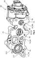
Figur 2 zeigt eine perspektivische Ansicht eines Anschlusselements der Befestigungsanordnung ausFigur 1 , -
Figur 3 zeigt eine Schnittansicht einer ersten Ausführung des Anschlusselements ausFigur 2 , und -
Figur 4 zeigt eine Schnittansicht einer zweiten Ausführung des Anschlusselements ausFigur 2 . - Die
Figur 1 zeigt ein Abgassystem 10 für einen Verbrennungsmotor 12 eines Kraftfahrzeugs. Der Verbrennungsmotor 12 weist einen Motorblock 14 auf, welcher vier Zylinder 16, 18, 20, 22 aufweist. Die Zylinder 16, 18, 20, 22 weisen jeweils einen Lufteinlass 24, 26, 28, 30 auf, durch welche Luft für die Verbrennungsprozesse in den Zylindern 16, 18, 20, 22 zugeführt werden kann. Die Lufteinlässe 24, 26, 28, 30 sind mit einem Lufteinlasskrümmer 32 verbunden, welcher mit einem Lufteinlasskanal 33 verbunden ist, wobei über den Lufteinlasskanal 33 Luft dem Lufteinlasskrümmer 32 zugeführt wird und die Luft durch den Lufteinlasskrümmer 32 auf die Lufteinlässe 24, 26, 28, 30 aufgeteilt wird. Weiterhin ist je Zylinder 16, 18, 20, 22 jeweils ein Kraftstoffinjektor 34, 36, 38, 40 vorgesehen, durch welche bedarfsgerecht Kraftstoff den jeweiligen Zylindern 16, 18, 20, 22 zugeführt werden kann. - Für den Ausstoß der beim Verbrennungsprozess entstandenen Abgase weisen die Zylinder 16, 18, 20, 22 jeweils einen Abgasauslass 42, 44, 46, 48 auf. Jeder Abgasauslass 42, 44, 46, 48 ist mit jeweils einer durch den Motorblock 14 erstreckenden Abgasleitung 50, 52, 54, 56 fluidisch verbunden, wobei die dem zweiten und dem dritten Zylindern 18, 20 zugeordneten Abgasleitungen 52, 54 zusammengeführt sind. Außerdem wird von der einem vierten Zylinder 22 zugeordneten Abgasleitung 56 eine Abgasrückführungsleitung 60 abgezweigt. Die Abgasrückführungsleitung 60 ist mit dem Lufteinlasskanal 33 fluidisch verbunden, so dass zumindest ein Teil des aus dem vierten Zylinder 22 strömenden Abgases dem Lufteinlasskanal 33 zugeführt werden kann. Damit dient ausschließlich das aus dem vierten Zylinder 22 ausgestoßene Abgas der Abgasrückführung zur Reduzierung von Schadstoffen.
- Das aus den Zylindern 16, 18, 20, 22 strömende Abgas wird außerdem zur Verdichtung der durch den Lufteinlasskanal 33 strömenden Luft genutzt, wobei das Abgas der Zylinder 16, 18, 20, 22 einer Turbine 64 eines Turboladers 62 zugeführt wird. Die Turbine 64 ist mit einem Verdichter 66 des Turboladers 62 drehfest verbunden, so dass der Verdichter 66 durch die Turbine 64 angetrieben wird und die für den Verbrennungsprozess erforderliche Luft verdichtet.
- Um die Abgase aller Zylinder 16, 18, 20, 22 der Turbine 64 des Turboladers 62 zuzuführen, ist ein Abgaskrümmer 70 vorgesehen, in welchen alle Abgasleitungen 50, 52, 54, 56 münden, wobei der Abgaskrümmer 70 alle Abgasmassenströme zusammenführt und ein einziger Abgasmassenstrom der Turbine 64 zugeführt wird.
- Die Verbindung zwischen dem Abgaskrümmer 70 und dem Motorblock 14 erfolgt über ein Anschlussflanschelement 72, wobei der Motorblock 14, der Abgaskrümmer 70 und das Anschlussflanschelement 72 gemeinsam eine Befestigungsanordnung 71 bilden. Das Anschlussflanschelement 72 ist aus Aluminium hergestellt und weist eine plane, motorseitige Flanschfläche 74, und eine plane abgaskrümmerseitige Flanschfläche 76 auf. An der motorseitigen Flanschfläche 74 ist der Motorblock 14 befestigt. An der abgaskrümmerseitigen Flanschfläche 76 ist der Abgaskrümmer 70 befestigt.
- Das Anschlussflanschelement 72 umfasst vier Durchtrittsöffnungen 77, 79, 83, 85, welche jeweils einen Abgaskanal 78, 80, 84, 86 begrenzen und dessen Längsachsen parallel zueinander verlaufen, wobei alle Durchtrittsöffnungen 77, 79, 83, 85 sich von der motorseitigen Flanschfläche 74 bis zur abgaskrümmerseitigen Flanschfläche 76 erstrecken. Ein erster Abgaskanal 78 ist der dem ersten Zylinder 16 zugeordneten Abgasleitung 50 zugeordnet. Ein zweiter Abgaskanal 80 ist den zusammengeführten Abgasleitungen 52, 54 der beiden Zylinder 18, 20 zugeordnet. Ein dritter Abgaskanal 84 und der vierte Abgaskanal 86 sind der dem vierten Zylinder 22 zugeordneten Abgasleitung 56 zugeordnet, wobei über den dritten Abgaskanal 84 die Abgasleitung 56 mit dem Abgaskrümmer 70 verbunden ist und über den vierten Abgaskanal 86 die Abgasleitung 56 mit der Abgasrückführungsleitung 60 verbunden ist. Die fluidische Verbindung der dem vierten Zylinder 22 zugeordneten Abgasleitung 56 mit dem Abgaskrümmer 70 oder mit der Abgasrückführungsleitung 60 wird durch eine Klappenvorrichtung 90 gesteuert. Die Klappenvorrichtung 90 umfasst einen Aktor 92, welcher eine Klappenwelle 94 antreibt. An der Klappenwelle 94 sind zwei Klappen 96, 98 befestigt, wobei eine erste Klappe 96 im dritten Abgaskanal 84 angeordnet ist und die zweite Klappe 98 im vierten Abgaskanal 86 angeordnet ist. Die beiden Klappen 96, 98 sind derart in den Abgaskanälen 84, 86 angeordnet, dass entweder der dritte Abgaskanal 84 oder der vierte Abgaskanal 86 geöffnet ist und damit in Offenstellung einer der beiden Klappen 96, 98 die andere Klappe 96, 98 den entsprechenden Abgaskanal 84, 86 verschließt.
- Dadurch kann eine Abgasrückführung freigegeben oder unterbunden werden, wobei bei einer freigegebenen Abgasrückführung das Abgas ausschließlich in die Abgasrückführungsleitung 60 strömen kann. Anderenfalls kann kein Abgas in die Abgasrückführungsleitung 60 strömen und das Abgas strömt vollständig zum Turbolader 62.
- Dadurch, dass das Anschlussflanschelement 72 vom heißen Abgas durchströmt wird, ist das Anschlussflanschelement 72 einer hohen thermischen Belastung ausgesetzt.
- Erfindungsgemäß sind zur Vermeidung einer thermischen Überlastung des Anschlussflanschelements 72 in der ersten Durchtrittsöffnung 77 und in der zweiten Durchtrittsöffnung 79 jeweils eine Hitzeschutz-Hülse 110, 112 angeordnet, wobei sich die Hitzeschutz-Hülsen 110, 112 axial von der motorseitigen Flanschfläche 74 bis zur abgaskrümmerseitigen Flanschfläche 76 erstrecken. In
Figur 3 ist ein Schnitt durch den Bereich der ersten Durchtrittsöffnung 77 und inFigur 4 ist ein Schnitt durch den Bereich der zweiten Durchtrittsöffnung 79 gezeigt. Zur Erhöhung der thermischen Abschottung zwischen dem heißen Abgas und dem Anschlussflanschelement 72 ist zwischen einer Außenumfangsfläche der Hitzeschutz-Hülse 110, 112 und der Umfangsflächen 114, 116 der Durchtrittsöffnungen 77, 79 ein Spalt 118, 120 vorgesehen, wodurch eine Luftspaltisolation geschaffen wird. - In
Figur 3 ist die Hitzeschutz-Hülse 110 zweiteilig und aus einem Stahlblech ausgeführt, wobei die Hitzeschutz-Hülse 110 ein erstes Hülsenelement 122 und ein zweites Hülsenelement 124 aufweist. Das erste Hülsenelement 122 erstreckt sich von der motorseitigen Flanschfläche 74 und ragt in die erste Durchtrittsöffnung 77. An dem der motorseitigen Flanschfläche 74 zugewandten Axialende des ersten Hülsenelements 122 ist ein radial erstreckender und umlaufender Kragen 126 ausgebildet, welcher in einem dazu korrespondierenden Absatz 128 an der motorseitigen Flanschfläche 74 angeordnet ist, so dass der Kragen 126 plan mit der motorseitigen Flanschfläche 74 ist und nicht axial hervorsteht. Des Weiteren ist am Kragen 126 eine Dichtsicke 127 vorgesehen. Das zweite Hülsenelement 124 erstreckt sich von der abgaskrümmerseitigen Flanschfläche 76 und weist ebenfalls einen radial erstreckenden Kragen 130 auf, welcher in einem an der abgaskrümmerseitigen Flanschfläche 76 vorgesehenen Absatz 132 angeordnet ist und eine Dichtsicke 131 aufweist. Die Dichtsicken 127, 131 dienen dazu, dass eine Anlage der Kragen 126, 130 an dem Anschlussflanschelement 72 im Bereich der Absätze 128, 132 und damit die Dichtigkeit in diesem Bereich gewährleistet ist. - Weiterhin weist das zweite Hülsenelement 124 an seinem dem ersten Hülsenelement 122 zugewandten Axialende eine Aufweitung 134 auf, wobei das erste Hülsenelement 122 im Bereich der Aufweitung in das zweite Hülsenelement 124 eingesteckt ist.
- In
Figur 4 ist die Hitzeschutz-Hülse 112 einteilig und aus einem Stahlblech ausgeführt. Die Hitzeschutz-Hülse 112 weist an einem ersten Axialende einen radial erstreckenden und umlaufenden Kragen 140 auf, welcher in einem an der abgaskrümmerseitigen Flanschfläche 76 vorgesehenen Absatz 142 angeordnet ist. An seinem entgegengesetzten Axialende wird die Hitzeschutz-Hülse 112 nach dem Einsetzen der Hitzeschutz-Hülse 112 in die zweite Durchtrittsöffnung 79 aufgebogen und damit mit dem Anschlussflanschelement 72 vercrimpt. Um den Luftspalt 120 abzudichten und die Vercrimpung zu vereinfachen, ist an der Umfangsfläche 116 der zweiten Durchtrittsöffnung 79 eine Fase 144 vorgesehen, wobei die Hitzeschutz-Hülse 112 nach der Vercrimpung mit dem umgebogenen Abschnitt im Bereich der Fase 144 am Anschlussflanschelement 72 anliegt. - Um die Gefahr eines thermischen Versagens des Anschlussflanschelements 72 nochmals zu reduzieren, sind außerdem im Anschlussflanschelement 72 Kühlmittelkanäle 100 vorgesehen, wobei ein derartiger Kühlmittelkanal 100 in den
Figuren 3 und 4 gezeigt ist. Der Kühlmittelkanal 100 umgibt den jeweiligen Abgaskanal 78, 80, 84, 86 radial. Durch die Kühlmittelkanäle 100 wird die von dem Abgas auf das Anschlusselement 72 übertragenen Wärme zumindest teilweise abgeführt. - Es sollte deutlich sein, dass der Schutzbereich des vorliegenden Hauptanspruchs nicht auf das beschriebene Ausführungsbeispiel beschränkt ist. So kann beispielsweise die Hitzeschutz-Hülse 110, 112 oder das Anschlussflanschelement 72 anders ausgeführt sein.
Claims (14)
- Befestigungsanordnung mit
einem Motorblock (14),
einem Abgaskrümmer (70), und
einem Anschlussflanschelement (72), welches über eine motorseitige Flanschfläche (74) am Motorblock (14) befestigt ist und über eine abgaskrümmerseitige Flanschfläche (76) am Abgaskrümmer (70) befestigt ist, wobei das Anschlussflanschelement (72) mehrere Durchtrittsöffnungen (77, 79, 83, 85) aufweist, welche sich von der motorseitigen Flanschfläche (74) bis zur abgaskrümmerseitigen Flanschfläche (76) erstrecken und jeweils einen Abgaskanal (78, 80, 84, 86) radial begrenzen,
dadurch gekennzeichnet, dass
in zumindest einer Durchtrittsöffnung (77, 79, 83, 85) eine Hitzeschutz-Hülse (110; 112) angeordnet ist, welche sich axial von der motorseitigen Flanschfläche (74) bis zur abgaskrümmerseitigen Flanschfläche (76) erstreckt. - Befestigungsanordnung nach Anspruch 1,
dadurch gekennzeichnet, dass
die Hitzeschutz-Hülse (110; 112) mit ihrer Außenumfangsfläche radial beabstandet von einer Umfangsfläche der Durchtrittsöffnung angeordnet ist, wobei die Hitzeschutz-Hülse (110; 112) mit der Umfangsfläche der Durchtrittsöffnung (77, 79, 83, 85) ein Luftspalt (118; 120) begrenzt. - Befestigungsanordnung nach Anspruch 1 oder 2,
dadurch gekennzeichnet, dass
die Hitzeschutz-Hülse (110; 112) aus einem Stahlblech hergestellt ist. - Befestigungsanordnung nach einem der vorhergehenden Ansprüche,
dadurch gekennzeichnet, dass
das Anschlussflanschelement (72) mindestens ein Kühlmittelkanal (100) aufweist, welcher von einem Kühlmittel durchströmt ist. - Befestigungsanordnung nach Anspruch 4,
dadurch gekennzeichnet, dass
der Kühlmittelkanal (100) die Durchtrittsöffnung (77, 79, 83, 85) radial umgibt. - Befestigungsanordnung nach einem der vorhergehenden Ansprüche,
dadurch gekennzeichnet, dass
die Hitzeschutz-Hülse (110) ein erstes Hülsenelement (122) und ein zweites Hülsenelement (124) aufweist, wobei sich das erste Hülsenelement (122) von der motorseitigen Flanschfläche (74) erstreckt und das zweite Hülsenelement (124) sich von der abgaskrümmerseitigen Flanschfläche (76) erstreckt, und wobei sich die beiden Hülsenelemente (122, 124) mit ihren zueinander zugewandten Enden überlappen. - Befestigungsanordnung nach Anspruch 6,
dadurch gekennzeichnet, dass
eines der beiden Hülsenelemente (122, 124) in das andere Hülsenelement (122, 124) eingesteckt ist. - Befestigungsanordnung nach Anspruch 7,
dadurch gekennzeichnet, dass
eines der beiden Hülsenelemente (122, 124) an dem dem anderen Hülsenelement (122, 124) zugewandten Ende eine radiale Aufweitung aufweist, wobei in die Aufweitung das Ende des anderen Hülsenelements (122, 124) eingesteckt ist. - Befestigungsanordnung nach Anspruch 8,
dadurch gekennzeichnet, dass
das eingesteckte Hülsenelement (122, 124) in Strömungsrichtung des Abgases vor dem anderen Hülsenelement (122, 124) angeordnet ist. - Befestigungsanordnung nach einem der vorhergehenden Ansprüche,
dadurch gekennzeichnet, dass
die Hitzeschutz-Hülse (110; 112) an zumindest einem der beiden Axialenden einen radial erstreckenden Kragen (126, 130; 140) aufweist, welcher an einer der beiden Flanschflächen (74, 76) anliegt. - Befestigungsanordnung nach Anspruch 10,
dadurch gekennzeichnet, dass
die Flanschfläche (74, 76) einen Absatz (128, 132; 142) aufweist, in welchem der Kragen (126, 130; 140) der Hitzeschutz-Hülse (110; 112) angeordnet ist. - Befestigungsanordnung nach Anspruch 10 oder 11,
dadurch gekennzeichnet, dass
der radial erstreckende Kragen (126, 130) eine Sicke (127, 131) aufweist, welche am Anschlussflanschelement (72) axial anliegt. - Befestigungsanordnung nach einem der vorhergehenden Ansprüche,
dadurch gekennzeichnet, dass
die Hitzeschutz-Hülse (110; 112) an zumindest einem der beiden Axialenden mit dem Anschlussflanschelement (72) vercrimpt ist. - Befestigungsanordnung nach Anspruch 13,
dadurch gekennzeichnet, dass
an einem Axialende einer Innenfläche der Durchtrittsöffnung eine Fase (144) vorgesehen ist und die Hitzeschutz-Hülse (112) am Axialende nach radial außen umgebogen ist.
Applications Claiming Priority (1)
| Application Number | Priority Date | Filing Date | Title |
|---|---|---|---|
| DE102020118177.9A DE102020118177A1 (de) | 2020-07-09 | 2020-07-09 | Befestigungsanordnung |
Publications (2)
| Publication Number | Publication Date |
|---|---|
| EP3936708A1 true EP3936708A1 (de) | 2022-01-12 |
| EP3936708B1 EP3936708B1 (de) | 2023-11-22 |
Family
ID=76829395
Family Applications (1)
| Application Number | Title | Priority Date | Filing Date |
|---|---|---|---|
| EP21184152.3A Active EP3936708B1 (de) | 2020-07-09 | 2021-07-07 | Befestigungsanordnung |
Country Status (2)
| Country | Link |
|---|---|
| EP (1) | EP3936708B1 (de) |
| DE (1) | DE102020118177A1 (de) |
Citations (4)
| Publication number | Priority date | Publication date | Assignee | Title |
|---|---|---|---|---|
| FR2169501A5 (de) * | 1972-01-28 | 1973-09-07 | Peugeot & Renault | |
| DE19752551A1 (de) * | 1997-08-13 | 1999-02-18 | Schmitz & Brill Gmbh & Co Kg | Flansch für eine mehrflutige Abgasanlage von Kraftfahrzeugen |
| DE102011050517A1 (de) | 2011-05-20 | 2012-11-22 | Pierburg Gmbh | Befestigungsanordnung |
| US20140109569A1 (en) * | 2012-10-22 | 2014-04-24 | Mazda Motor Corporation | Exhaust gas recirculation system for engine |
Family Cites Families (2)
| Publication number | Priority date | Publication date | Assignee | Title |
|---|---|---|---|---|
| JP2001263056A (ja) | 2000-03-14 | 2001-09-26 | Aisin Takaoka Ltd | 排気管の接合構造 |
| DE102004024831A1 (de) | 2004-05-19 | 2005-12-08 | Arvin Technologies, Inc., Troy | Verfahren zum Herstellen einer Flanschanbindung und Abgasstrang-Flanschanbindung |
-
2020
- 2020-07-09 DE DE102020118177.9A patent/DE102020118177A1/de not_active Ceased
-
2021
- 2021-07-07 EP EP21184152.3A patent/EP3936708B1/de active Active
Patent Citations (4)
| Publication number | Priority date | Publication date | Assignee | Title |
|---|---|---|---|---|
| FR2169501A5 (de) * | 1972-01-28 | 1973-09-07 | Peugeot & Renault | |
| DE19752551A1 (de) * | 1997-08-13 | 1999-02-18 | Schmitz & Brill Gmbh & Co Kg | Flansch für eine mehrflutige Abgasanlage von Kraftfahrzeugen |
| DE102011050517A1 (de) | 2011-05-20 | 2012-11-22 | Pierburg Gmbh | Befestigungsanordnung |
| US20140109569A1 (en) * | 2012-10-22 | 2014-04-24 | Mazda Motor Corporation | Exhaust gas recirculation system for engine |
Also Published As
| Publication number | Publication date |
|---|---|
| DE102020118177A1 (de) | 2022-01-13 |
| EP3936708B1 (de) | 2023-11-22 |
Similar Documents
| Publication | Publication Date | Title |
|---|---|---|
| EP2075430B1 (de) | Abgassammler | |
| EP2041419B1 (de) | Abgaskühler, insbesondere für ein kraftfahrzeug | |
| EP2379864A1 (de) | Verbindungsanordnung eines turbinengehäuses mit einem lagergehäuse und abgasturbolader | |
| EP1531238B1 (de) | Gehäuseanordnung für den Turbolader einer Brennkraftmaschine | |
| EP2558703A1 (de) | Abgaskühlmodul für eine verbrennungskraftmaschine | |
| EP2587036B1 (de) | Brennkraftmaschine | |
| EP1389267B1 (de) | Abgaskrümmer | |
| EP3315751B1 (de) | Zylinderkopf mit angeschlossenem auspuffkrümmer einer brennkraftmaschine | |
| EP2877722B1 (de) | Brennkraftmaschine mit frischluftversorgungseinrichtung | |
| DE60207363T2 (de) | Ventil für die Steuerung der Zufuhr des Abkühlungsluftstromes einer Turbine | |
| DE112015006356T5 (de) | Verteiler-dichtfläche für verbesserte balginstallation | |
| EP3936708B1 (de) | Befestigungsanordnung | |
| EP0282497B1 (de) | Halterung einer abgasleitung | |
| DE112014003266T5 (de) | Hochtemperatur-Ventilschaftdichtung | |
| EP3705696A1 (de) | Klappenvorrichtung für eine verbrennungskraftmaschine | |
| EP1182344B1 (de) | Vorrichtung zur Rückführung von Gas an einem Verbrennungsmotor | |
| EP3918190B1 (de) | Vorrichtung zur abgasführung für eine brennkraftmaschine | |
| DE102004051680B4 (de) | Anordnung zur Befestigung eines Abgaskrümmers | |
| DE102019202380B4 (de) | Brennkraftmaschine mit einem Abgaskrümmer und einem Abgasturbolader | |
| DE112017003009T5 (de) | Fahrzeugabgassystem | |
| WO2021160411A1 (de) | Verbrennungskraftmaschine für ein kraftfahrzeug, insbesondere für einen kraftwagen | |
| DE102022101656B4 (de) | Abgasrückführkühler, insbesondere für ein Kraftfahrzeug, sowie Kraftfahrzeug | |
| DE102022000117A1 (de) | Einsatz für einen Auslasskanal | |
| DE102004021894B4 (de) | Luftspaltisoliertes Abgasrohr | |
| DE102011085161B4 (de) | Kühlbares strömungsführendes Gehäuse einer Abgaskomponente |
Legal Events
| Date | Code | Title | Description |
|---|---|---|---|
| PUAI | Public reference made under article 153(3) epc to a published international application that has entered the european phase |
Free format text: ORIGINAL CODE: 0009012 |
|
| STAA | Information on the status of an ep patent application or granted ep patent |
Free format text: STATUS: THE APPLICATION HAS BEEN PUBLISHED |
|
| AK | Designated contracting states |
Kind code of ref document: A1 Designated state(s): AL AT BE BG CH CY CZ DE DK EE ES FI FR GB GR HR HU IE IS IT LI LT LU LV MC MK MT NL NO PL PT RO RS SE SI SK SM TR |
|
| B565 | Issuance of search results under rule 164(2) epc |
Effective date: 20211206 |
|
| STAA | Information on the status of an ep patent application or granted ep patent |
Free format text: STATUS: REQUEST FOR EXAMINATION WAS MADE |
|
| 17P | Request for examination filed |
Effective date: 20220712 |
|
| RBV | Designated contracting states (corrected) |
Designated state(s): AL AT BE BG CH CY CZ DE DK EE ES FI FR GB GR HR HU IE IS IT LI LT LU LV MC MK MT NL NO PL PT RO RS SE SI SK SM TR |
|
| GRAP | Despatch of communication of intention to grant a patent |
Free format text: ORIGINAL CODE: EPIDOSNIGR1 |
|
| STAA | Information on the status of an ep patent application or granted ep patent |
Free format text: STATUS: GRANT OF PATENT IS INTENDED |
|
| RIC1 | Information provided on ipc code assigned before grant |
Ipc: F02M 26/43 20160101ALI20230526BHEP Ipc: F02M 26/16 20160101ALI20230526BHEP Ipc: F01N 13/18 20100101ALI20230526BHEP Ipc: F01N 13/10 20100101AFI20230526BHEP |
|
| INTG | Intention to grant announced |
Effective date: 20230616 |
|
| GRAS | Grant fee paid |
Free format text: ORIGINAL CODE: EPIDOSNIGR3 |
|
| GRAA | (expected) grant |
Free format text: ORIGINAL CODE: 0009210 |
|
| STAA | Information on the status of an ep patent application or granted ep patent |
Free format text: STATUS: THE PATENT HAS BEEN GRANTED |
|
| AK | Designated contracting states |
Kind code of ref document: B1 Designated state(s): AL AT BE BG CH CY CZ DE DK EE ES FI FR GB GR HR HU IE IS IT LI LT LU LV MC MK MT NL NO PL PT RO RS SE SI SK SM TR |
|
| REG | Reference to a national code |
Ref country code: GB Ref legal event code: FG4D Free format text: NOT ENGLISH |
|
| REG | Reference to a national code |
Ref country code: CH Ref legal event code: EP Ref country code: DE Ref legal event code: R096 Ref document number: 502021002004 Country of ref document: DE |
|
| REG | Reference to a national code |
Ref country code: IE Ref legal event code: FG4D Free format text: LANGUAGE OF EP DOCUMENT: GERMAN |
|
| REG | Reference to a national code |
Ref country code: LT Ref legal event code: MG9D |
|
| REG | Reference to a national code |
Ref country code: NL Ref legal event code: MP Effective date: 20231122 |
|
| PG25 | Lapsed in a contracting state [announced via postgrant information from national office to epo] |
Ref country code: GR Free format text: LAPSE BECAUSE OF FAILURE TO SUBMIT A TRANSLATION OF THE DESCRIPTION OR TO PAY THE FEE WITHIN THE PRESCRIBED TIME-LIMIT Effective date: 20240223 |
|
| PG25 | Lapsed in a contracting state [announced via postgrant information from national office to epo] |
Ref country code: IS Free format text: LAPSE BECAUSE OF FAILURE TO SUBMIT A TRANSLATION OF THE DESCRIPTION OR TO PAY THE FEE WITHIN THE PRESCRIBED TIME-LIMIT Effective date: 20240322 |
|
| PG25 | Lapsed in a contracting state [announced via postgrant information from national office to epo] |
Ref country code: LT Free format text: LAPSE BECAUSE OF FAILURE TO SUBMIT A TRANSLATION OF THE DESCRIPTION OR TO PAY THE FEE WITHIN THE PRESCRIBED TIME-LIMIT Effective date: 20231122 |
|
| PG25 | Lapsed in a contracting state [announced via postgrant information from national office to epo] |
Ref country code: NL Free format text: LAPSE BECAUSE OF FAILURE TO SUBMIT A TRANSLATION OF THE DESCRIPTION OR TO PAY THE FEE WITHIN THE PRESCRIBED TIME-LIMIT Effective date: 20231122 |
|
| PG25 | Lapsed in a contracting state [announced via postgrant information from national office to epo] |
Ref country code: ES Free format text: LAPSE BECAUSE OF FAILURE TO SUBMIT A TRANSLATION OF THE DESCRIPTION OR TO PAY THE FEE WITHIN THE PRESCRIBED TIME-LIMIT Effective date: 20231122 |
|
| PG25 | Lapsed in a contracting state [announced via postgrant information from national office to epo] |
Ref country code: NL Free format text: LAPSE BECAUSE OF FAILURE TO SUBMIT A TRANSLATION OF THE DESCRIPTION OR TO PAY THE FEE WITHIN THE PRESCRIBED TIME-LIMIT Effective date: 20231122 Ref country code: LT Free format text: LAPSE BECAUSE OF FAILURE TO SUBMIT A TRANSLATION OF THE DESCRIPTION OR TO PAY THE FEE WITHIN THE PRESCRIBED TIME-LIMIT Effective date: 20231122 Ref country code: IS Free format text: LAPSE BECAUSE OF FAILURE TO SUBMIT A TRANSLATION OF THE DESCRIPTION OR TO PAY THE FEE WITHIN THE PRESCRIBED TIME-LIMIT Effective date: 20240322 Ref country code: GR Free format text: LAPSE BECAUSE OF FAILURE TO SUBMIT A TRANSLATION OF THE DESCRIPTION OR TO PAY THE FEE WITHIN THE PRESCRIBED TIME-LIMIT Effective date: 20240223 Ref country code: ES Free format text: LAPSE BECAUSE OF FAILURE TO SUBMIT A TRANSLATION OF THE DESCRIPTION OR TO PAY THE FEE WITHIN THE PRESCRIBED TIME-LIMIT Effective date: 20231122 Ref country code: BG Free format text: LAPSE BECAUSE OF FAILURE TO SUBMIT A TRANSLATION OF THE DESCRIPTION OR TO PAY THE FEE WITHIN THE PRESCRIBED TIME-LIMIT Effective date: 20240222 Ref country code: PT Free format text: LAPSE BECAUSE OF FAILURE TO SUBMIT A TRANSLATION OF THE DESCRIPTION OR TO PAY THE FEE WITHIN THE PRESCRIBED TIME-LIMIT Effective date: 20240322 |
|
| PG25 | Lapsed in a contracting state [announced via postgrant information from national office to epo] |
Ref country code: SE Free format text: LAPSE BECAUSE OF FAILURE TO SUBMIT A TRANSLATION OF THE DESCRIPTION OR TO PAY THE FEE WITHIN THE PRESCRIBED TIME-LIMIT Effective date: 20231122 Ref country code: RS Free format text: LAPSE BECAUSE OF FAILURE TO SUBMIT A TRANSLATION OF THE DESCRIPTION OR TO PAY THE FEE WITHIN THE PRESCRIBED TIME-LIMIT Effective date: 20231122 Ref country code: PL Free format text: LAPSE BECAUSE OF FAILURE TO SUBMIT A TRANSLATION OF THE DESCRIPTION OR TO PAY THE FEE WITHIN THE PRESCRIBED TIME-LIMIT Effective date: 20231122 Ref country code: NO Free format text: LAPSE BECAUSE OF FAILURE TO SUBMIT A TRANSLATION OF THE DESCRIPTION OR TO PAY THE FEE WITHIN THE PRESCRIBED TIME-LIMIT Effective date: 20240222 Ref country code: LV Free format text: LAPSE BECAUSE OF FAILURE TO SUBMIT A TRANSLATION OF THE DESCRIPTION OR TO PAY THE FEE WITHIN THE PRESCRIBED TIME-LIMIT Effective date: 20231122 Ref country code: HR Free format text: LAPSE BECAUSE OF FAILURE TO SUBMIT A TRANSLATION OF THE DESCRIPTION OR TO PAY THE FEE WITHIN THE PRESCRIBED TIME-LIMIT Effective date: 20231122 |
|
| PG25 | Lapsed in a contracting state [announced via postgrant information from national office to epo] |
Ref country code: DK Free format text: LAPSE BECAUSE OF FAILURE TO SUBMIT A TRANSLATION OF THE DESCRIPTION OR TO PAY THE FEE WITHIN THE PRESCRIBED TIME-LIMIT Effective date: 20231122 |
|
| PG25 | Lapsed in a contracting state [announced via postgrant information from national office to epo] |
Ref country code: CZ Free format text: LAPSE BECAUSE OF FAILURE TO SUBMIT A TRANSLATION OF THE DESCRIPTION OR TO PAY THE FEE WITHIN THE PRESCRIBED TIME-LIMIT Effective date: 20231122 |
|
| PG25 | Lapsed in a contracting state [announced via postgrant information from national office to epo] |
Ref country code: SK Free format text: LAPSE BECAUSE OF FAILURE TO SUBMIT A TRANSLATION OF THE DESCRIPTION OR TO PAY THE FEE WITHIN THE PRESCRIBED TIME-LIMIT Effective date: 20231122 |
|
| PG25 | Lapsed in a contracting state [announced via postgrant information from national office to epo] |
Ref country code: SM Free format text: LAPSE BECAUSE OF FAILURE TO SUBMIT A TRANSLATION OF THE DESCRIPTION OR TO PAY THE FEE WITHIN THE PRESCRIBED TIME-LIMIT Effective date: 20231122 Ref country code: SK Free format text: LAPSE BECAUSE OF FAILURE TO SUBMIT A TRANSLATION OF THE DESCRIPTION OR TO PAY THE FEE WITHIN THE PRESCRIBED TIME-LIMIT Effective date: 20231122 Ref country code: RO Free format text: LAPSE BECAUSE OF FAILURE TO SUBMIT A TRANSLATION OF THE DESCRIPTION OR TO PAY THE FEE WITHIN THE PRESCRIBED TIME-LIMIT Effective date: 20231122 Ref country code: IT Free format text: LAPSE BECAUSE OF FAILURE TO SUBMIT A TRANSLATION OF THE DESCRIPTION OR TO PAY THE FEE WITHIN THE PRESCRIBED TIME-LIMIT Effective date: 20231122 Ref country code: EE Free format text: LAPSE BECAUSE OF FAILURE TO SUBMIT A TRANSLATION OF THE DESCRIPTION OR TO PAY THE FEE WITHIN THE PRESCRIBED TIME-LIMIT Effective date: 20231122 Ref country code: DK Free format text: LAPSE BECAUSE OF FAILURE TO SUBMIT A TRANSLATION OF THE DESCRIPTION OR TO PAY THE FEE WITHIN THE PRESCRIBED TIME-LIMIT Effective date: 20231122 Ref country code: CZ Free format text: LAPSE BECAUSE OF FAILURE TO SUBMIT A TRANSLATION OF THE DESCRIPTION OR TO PAY THE FEE WITHIN THE PRESCRIBED TIME-LIMIT Effective date: 20231122 |
|
| REG | Reference to a national code |
Ref country code: DE Ref legal event code: R097 Ref document number: 502021002004 Country of ref document: DE |
|
| PLBE | No opposition filed within time limit |
Free format text: ORIGINAL CODE: 0009261 |
|
| STAA | Information on the status of an ep patent application or granted ep patent |
Free format text: STATUS: NO OPPOSITION FILED WITHIN TIME LIMIT |
|
| PG25 | Lapsed in a contracting state [announced via postgrant information from national office to epo] |
Ref country code: SI Free format text: LAPSE BECAUSE OF FAILURE TO SUBMIT A TRANSLATION OF THE DESCRIPTION OR TO PAY THE FEE WITHIN THE PRESCRIBED TIME-LIMIT Effective date: 20231122 |
|
| 26N | No opposition filed |
Effective date: 20240823 |
|
| PG25 | Lapsed in a contracting state [announced via postgrant information from national office to epo] |
Ref country code: SI Free format text: LAPSE BECAUSE OF FAILURE TO SUBMIT A TRANSLATION OF THE DESCRIPTION OR TO PAY THE FEE WITHIN THE PRESCRIBED TIME-LIMIT Effective date: 20231122 |
|
| PG25 | Lapsed in a contracting state [announced via postgrant information from national office to epo] |
Ref country code: MC Free format text: LAPSE BECAUSE OF FAILURE TO SUBMIT A TRANSLATION OF THE DESCRIPTION OR TO PAY THE FEE WITHIN THE PRESCRIBED TIME-LIMIT Effective date: 20231122 |
|
| REG | Reference to a national code |
Ref country code: CH Ref legal event code: PL |
|
| PG25 | Lapsed in a contracting state [announced via postgrant information from national office to epo] |
Ref country code: LU Free format text: LAPSE BECAUSE OF NON-PAYMENT OF DUE FEES Effective date: 20240707 |
|
| PG25 | Lapsed in a contracting state [announced via postgrant information from national office to epo] |
Ref country code: LU Free format text: LAPSE BECAUSE OF NON-PAYMENT OF DUE FEES Effective date: 20240707 |
|
| PG25 | Lapsed in a contracting state [announced via postgrant information from national office to epo] |
Ref country code: BE Free format text: LAPSE BECAUSE OF NON-PAYMENT OF DUE FEES Effective date: 20240731 Ref country code: CH Free format text: LAPSE BECAUSE OF NON-PAYMENT OF DUE FEES Effective date: 20240731 |
|
| PG25 | Lapsed in a contracting state [announced via postgrant information from national office to epo] |
Ref country code: FR Free format text: LAPSE BECAUSE OF NON-PAYMENT OF DUE FEES Effective date: 20240731 |
|
| REG | Reference to a national code |
Ref country code: BE Ref legal event code: MM Effective date: 20240731 |
|
| PG25 | Lapsed in a contracting state [announced via postgrant information from national office to epo] |
Ref country code: IE Free format text: LAPSE BECAUSE OF NON-PAYMENT OF DUE FEES Effective date: 20240707 |
|
| PG25 | Lapsed in a contracting state [announced via postgrant information from national office to epo] |
Ref country code: FI Free format text: LAPSE BECAUSE OF FAILURE TO SUBMIT A TRANSLATION OF THE DESCRIPTION OR TO PAY THE FEE WITHIN THE PRESCRIBED TIME-LIMIT Effective date: 20231122 |
|
| PGFP | Annual fee paid to national office [announced via postgrant information from national office to epo] |
Ref country code: DE Payment date: 20250722 Year of fee payment: 5 |
|
| PGFP | Annual fee paid to national office [announced via postgrant information from national office to epo] |
Ref country code: AT Payment date: 20251020 Year of fee payment: 5 |
|
| PG25 | Lapsed in a contracting state [announced via postgrant information from national office to epo] |
Ref country code: CY Free format text: LAPSE BECAUSE OF FAILURE TO SUBMIT A TRANSLATION OF THE DESCRIPTION OR TO PAY THE FEE WITHIN THE PRESCRIBED TIME-LIMIT; INVALID AB INITIO Effective date: 20210707 |
|
| REG | Reference to a national code |
Ref country code: DE Ref legal event code: R082 Ref document number: 502021002004 Country of ref document: DE |
|
| PG25 | Lapsed in a contracting state [announced via postgrant information from national office to epo] |
Ref country code: HU Free format text: LAPSE BECAUSE OF FAILURE TO SUBMIT A TRANSLATION OF THE DESCRIPTION OR TO PAY THE FEE WITHIN THE PRESCRIBED TIME-LIMIT; INVALID AB INITIO Effective date: 20210707 |
|
| GBPC | Gb: european patent ceased through non-payment of renewal fee |
Effective date: 20250707 |
|
| PG25 | Lapsed in a contracting state [announced via postgrant information from national office to epo] |
Ref country code: GB Free format text: LAPSE BECAUSE OF NON-PAYMENT OF DUE FEES Effective date: 20250707 |