EP3936483A1 - Method for manufacturing optical fiber - Google Patents
Method for manufacturing optical fiber Download PDFInfo
- Publication number
- EP3936483A1 EP3936483A1 EP21181416.5A EP21181416A EP3936483A1 EP 3936483 A1 EP3936483 A1 EP 3936483A1 EP 21181416 A EP21181416 A EP 21181416A EP 3936483 A1 EP3936483 A1 EP 3936483A1
- Authority
- EP
- European Patent Office
- Prior art keywords
- optical fiber
- peak
- frequency
- outer diameter
- glass
- Prior art date
- Legal status (The legal status is an assumption and is not a legal conclusion. Google has not performed a legal analysis and makes no representation as to the accuracy of the status listed.)
- Granted
Links
Images


Classifications
-
- C—CHEMISTRY; METALLURGY
- C03—GLASS; MINERAL OR SLAG WOOL
- C03B—MANUFACTURE, SHAPING, OR SUPPLEMENTARY PROCESSES
- C03B37/00—Manufacture or treatment of flakes, fibres, or filaments from softened glass, minerals, or slags
- C03B37/01—Manufacture of glass fibres or filaments
- C03B37/02—Manufacture of glass fibres or filaments by drawing or extruding, e.g. direct drawing of molten glass from nozzles; Cooling fins therefor
- C03B37/025—Manufacture of glass fibres or filaments by drawing or extruding, e.g. direct drawing of molten glass from nozzles; Cooling fins therefor from reheated softened tubes, rods, fibres or filaments, e.g. drawing fibres from preforms
- C03B37/027—Fibres composed of different sorts of glass, e.g. glass optical fibres
- C03B37/02718—Thermal treatment of the fibre during the drawing process, e.g. cooling
-
- C—CHEMISTRY; METALLURGY
- C03—GLASS; MINERAL OR SLAG WOOL
- C03B—MANUFACTURE, SHAPING, OR SUPPLEMENTARY PROCESSES
- C03B37/00—Manufacture or treatment of flakes, fibres, or filaments from softened glass, minerals, or slags
- C03B37/01—Manufacture of glass fibres or filaments
- C03B37/02—Manufacture of glass fibres or filaments by drawing or extruding, e.g. direct drawing of molten glass from nozzles; Cooling fins therefor
- C03B37/025—Manufacture of glass fibres or filaments by drawing or extruding, e.g. direct drawing of molten glass from nozzles; Cooling fins therefor from reheated softened tubes, rods, fibres or filaments, e.g. drawing fibres from preforms
- C03B37/027—Fibres composed of different sorts of glass, e.g. glass optical fibres
- C03B37/02745—Fibres having rotational spin around the central longitudinal axis, e.g. alternating +/- spin to reduce polarisation mode dispersion
-
- C—CHEMISTRY; METALLURGY
- C03—GLASS; MINERAL OR SLAG WOOL
- C03B—MANUFACTURE, SHAPING, OR SUPPLEMENTARY PROCESSES
- C03B37/00—Manufacture or treatment of flakes, fibres, or filaments from softened glass, minerals, or slags
- C03B37/01—Manufacture of glass fibres or filaments
- C03B37/02—Manufacture of glass fibres or filaments by drawing or extruding, e.g. direct drawing of molten glass from nozzles; Cooling fins therefor
- C03B37/025—Manufacture of glass fibres or filaments by drawing or extruding, e.g. direct drawing of molten glass from nozzles; Cooling fins therefor from reheated softened tubes, rods, fibres or filaments, e.g. drawing fibres from preforms
- C03B37/0253—Controlling or regulating
-
- C—CHEMISTRY; METALLURGY
- C03—GLASS; MINERAL OR SLAG WOOL
- C03B—MANUFACTURE, SHAPING, OR SUPPLEMENTARY PROCESSES
- C03B37/00—Manufacture or treatment of flakes, fibres, or filaments from softened glass, minerals, or slags
- C03B37/01—Manufacture of glass fibres or filaments
- C03B37/02—Manufacture of glass fibres or filaments by drawing or extruding, e.g. direct drawing of molten glass from nozzles; Cooling fins therefor
- C03B37/025—Manufacture of glass fibres or filaments by drawing or extruding, e.g. direct drawing of molten glass from nozzles; Cooling fins therefor from reheated softened tubes, rods, fibres or filaments, e.g. drawing fibres from preforms
- C03B37/029—Furnaces therefor
-
- C—CHEMISTRY; METALLURGY
- C03—GLASS; MINERAL OR SLAG WOOL
- C03B—MANUFACTURE, SHAPING, OR SUPPLEMENTARY PROCESSES
- C03B37/00—Manufacture or treatment of flakes, fibres, or filaments from softened glass, minerals, or slags
- C03B37/01—Manufacture of glass fibres or filaments
- C03B37/02—Manufacture of glass fibres or filaments by drawing or extruding, e.g. direct drawing of molten glass from nozzles; Cooling fins therefor
- C03B37/03—Drawing means, e.g. drawing drums ; Traction or tensioning devices
-
- C—CHEMISTRY; METALLURGY
- C03—GLASS; MINERAL OR SLAG WOOL
- C03B—MANUFACTURE, SHAPING, OR SUPPLEMENTARY PROCESSES
- C03B37/00—Manufacture or treatment of flakes, fibres, or filaments from softened glass, minerals, or slags
- C03B37/10—Non-chemical treatment
- C03B37/12—Non-chemical treatment of fibres or filaments during winding up
-
- C—CHEMISTRY; METALLURGY
- C03—GLASS; MINERAL OR SLAG WOOL
- C03C—CHEMICAL COMPOSITION OF GLASSES, GLAZES OR VITREOUS ENAMELS; SURFACE TREATMENT OF GLASS; SURFACE TREATMENT OF FIBRES OR FILAMENTS MADE FROM GLASS, MINERALS OR SLAGS; JOINING GLASS TO GLASS OR OTHER MATERIALS
- C03C13/00—Fibre or filament compositions
- C03C13/04—Fibre optics, e.g. core and clad fibre compositions
-
- G—PHYSICS
- G02—OPTICS
- G02B—OPTICAL ELEMENTS, SYSTEMS OR APPARATUS
- G02B6/00—Light guides; Structural details of arrangements comprising light guides and other optical elements, e.g. couplings
- G02B6/02—Optical fibres with cladding with or without a coating
- G02B6/02033—Core or cladding made from organic material, e.g. polymeric material
-
- C—CHEMISTRY; METALLURGY
- C03—GLASS; MINERAL OR SLAG WOOL
- C03B—MANUFACTURE, SHAPING, OR SUPPLEMENTARY PROCESSES
- C03B2203/00—Fibre product details, e.g. structure, shape
- C03B2203/36—Dispersion modified fibres, e.g. wavelength or polarisation shifted, flattened or compensating fibres (DSF, DFF, DCF)
-
- C—CHEMISTRY; METALLURGY
- C03—GLASS; MINERAL OR SLAG WOOL
- C03B—MANUFACTURE, SHAPING, OR SUPPLEMENTARY PROCESSES
- C03B2205/00—Fibre drawing or extruding details
- C03B2205/40—Monitoring or regulating the draw tension or draw rate
-
- C—CHEMISTRY; METALLURGY
- C03—GLASS; MINERAL OR SLAG WOOL
- C03B—MANUFACTURE, SHAPING, OR SUPPLEMENTARY PROCESSES
- C03B2205/00—Fibre drawing or extruding details
- C03B2205/55—Cooling or annealing the drawn fibre prior to coating using a series of coolers or heaters
-
- C—CHEMISTRY; METALLURGY
- C03—GLASS; MINERAL OR SLAG WOOL
- C03B—MANUFACTURE, SHAPING, OR SUPPLEMENTARY PROCESSES
- C03B2205/00—Fibre drawing or extruding details
- C03B2205/60—Optical fibre draw furnaces
- C03B2205/62—Heating means for drawing
Definitions
- the present disclosure relates to a method for manufacturing an optical fiber.
- Japanese Unexamined Patent Application Publication No. 2016 79073 discloses a method for suppressing the variation of the outer diameter of the optical fiber glass due to the vibration of the drawing tower by providing a vibration suppressing mechanism having a time constant of 1 seconds or less between the drawing tower and the optical fiber preform.
- the present disclosure provides a method for manufacturing an optical fiber.
- the method includes: heating an optical fiber preform to draw glass fiber; measuring an outer diameter of the glass fiber to obtain a function of time; transforming the function of time into a function of frequency; identifying a first peak caused by a first drawing condition and a second peak caused by a second drawing condition in the function of frequency; and adjusting the second drawing condition so as to satisfy fn ⁇ fm - wm / 2 or fn > fm + wm / 2, where fm is a frequency of the first peak, wm is a full width at half maximum of the first peak, and fn is a frequency of the second peak.
- Japanese Unexamined Patent Application Publication No. 1996-295528 discloses a method for suppressing PMD by periodically swinging a guide roller and twisting an optical fiber.
- the outer diameter of the glass is varied by changing the traveling position and distance of the optical fiber.
- a variation in the outer diameter of the glass may specifically deteriorate under certain conditions.
- a method for remarkably reducing the drawing speed or reducing the twisting as much as possible is adopted.
- productivity and yield are severely compromised.
- the variation of the glass outer diameter is improved to some extent, but it is not enough.
- An object of the present disclosure is to provide a method for manufacturing an optical fiber capable of further suppressing a variation in the outer diameter of glass without deteriorating productivity and yield.
- a method for manufacturing an optical fiber includes: heating an optical fiber preform to draw glass fiber; measuring an outer diameter of the glass fiber to obtain a function of time; transforming the function of time into a function of frequency; identifying a first peak caused by a first drawing condition and a second peak caused by a second drawing condition in the function of frequency; and adjusting the second drawing condition so as to satisfy fn ⁇ fm - wm / 2 or fn > fm + wm / 2, where fm is a frequency of the first peak, wm is a full width at half maximum of the first peak, and fn is a frequency of the second peak.
- the second drawing condition is adjusted so that the first peak caused by the first drawing condition and the second peak caused by the second drawing condition do not overlap each other.
- the occurrence of a large amplitude due to the overlap of the first peak and the second peak is suppressed. Therefore, it is possible to further suppress the deterioration of the variation of the glass outer diameter without deteriorating the productivity and the yield.
- a sampling time interval of the outer diameter may be 100 ms or less. In this case, it is possible to surely detect the short-period variation of the glass outer diameter.
- the method for manufacturing an optical fiber may further include forming a coating layer on the glass fiber to form an optical fiber; and twisting the optical fiber using a swing guide roller.
- the swing frequency of the swing guide roller may be the second drawing condition, and a second peak may be generated by the swing frequency. Therefore, it is more effective to prevent the first peak and the second peak from overlapping each other.
- the second drawing condition may be a swing frequency of the swing guide roller.
- the swing frequency of the swing guide roller it is possible to further suppress the deterioration of the variation of the glass outer diameter without deteriorating the productivity and the yield.
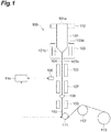
- FIG. 1 is a configuration diagram of a manufacturing device used in the method for manufacturing an optical fiber according to the embodiment.
- the manufacturing device 100 (drawing device) shown in FIG. 1 is a device for manufacturing the optical fiber 110 from the optical fiber preform 101 via the glass fiber 104.
- a manufacturing device 100 is provided with a gripper 102, a heating furnace 103, a thermal insulation furnace 105, a measuring instrument 106, a cooler 107, a die 108, an ultraviolet irradiation device 109, a swing guide roller 111, a capstan 112, a winder 113, and a controller 114.
- the gripper 102 grips the optical fiber preform 101 and feeds it into the heating furnace 103 at a constant speed.
- the optical fiber preform 101 includes a base end portion 101a gripped by the gripper 102 and a tip portion 101b inserted into the heating furnace 103.
- the gripper 102 functions as a supplier for supplying the optical fiber preform 101 to the heating furnace 103.
- the heating furnace 103 includes openings 103a and 103b.
- the optical fiber preform 101 is inserted into the opening 103a.
- the opening 103b faces the opening 103a.
- the glass fiber 104 is drawn out from the opening 103b.
- the heating furnace 103 heats and softens the tip portion 101b of the optical fiber preform 101 supplied into the heating furnace 103.
- the glass fiber 104 is drawn out from the tip portion 101b softened by heating.
- the glass fiber 104 is drawn out of the heating furnace 103 through the opening 103b.
- the thermal insulation furnace 105 keeps the glass fiber 104 warm and relaxes the structure of the glass.
- the measuring instrument 106 measures the outer diameter (glass outer diameter) of the glass fiber 104 in a state where the glass structure is relaxed.
- the measuring instrument 106 measures the outer diameter of the glass by irradiating the glass fiber 104 with a laser.
- the sampling time interval of the outer diameter of the glass by the measuring instrument 106 is, for example, 100 ms or less. Depending on the drawing speed, there is a possibility that the variation of the short period of the glass outer diameter cannot be detected when the sampling interval becomes long.
- the measuring instrument 106 transmits the measured outer diameter of the glass to the controller 114.
- a cooler 107 is located after the measuring instrument 106 to cool the glass fiber 104.
- the die 108 applies resin to the outer peripheral surface of the glass fiber 104 to form a coating resin.
- the resin includes an acrylate-based ultraviolet curable resin.
- the ultraviolet irradiation device 109 irradiates the coating resin formed on the glass fiber 104 with ultraviolet rays to cure the coating resin. As a result, the glass fiber is coated with the resin to form the optical fiber 110.
- the swing guide roller 111 periodically tilts its axial direction to twist the optical fiber 110.
- the swing guide roller 111 is electrically connected to the controller 114, and is controlled and oscillated by the controller 114 to impart a twist to the optical fiber 110.
- a pair of fixed guide rollers may be disposed in front of and behind the swing guide roller 111, it is not possible to completely prevent the swing of the swing guide roller 111 from being transmitted to other portions.
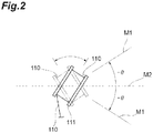
- FIG. 2 is a diagram of the swing guide roller as viewed from the upstream side of the pass line (the ultraviolet irradiation device side).
- the swing guide roller 111 swings within the range of ⁇ ⁇ in the angle formed by the rotation axis M1 and the predetermined axis M2.
- a lateral force is applied to the optical fiber 110, and the optical fiber 110 rolls on the surface of the swing guide roller 111 to twist the optical fiber 110.
- the optical fiber 110 is twisted in the opposite direction.
- the optical fiber 110 is alternately twisted clockwise and counterclockwise with respect to the traveling direction (drawing direction) by repeating a symmetrical reciprocating motion in which the swing guide roller 111 swings at an angle ⁇ ⁇ with respect to a predetermined axis M2.
- the swing guide roller 111 guides the optical fiber 110 to the capstan 112 while twisting the optical fiber 110.
- the capstan 112 pulls the optical fiber 110 at a predetermined speed and tension.
- the winder 113 winds the optical fiber 110 drawn by the capstan 112.
- the controller 114 receives the glass outer diameter measured by the measuring instrument 106 from the measuring instrument 106, and feedback-controls the swing of the swing guide roller 111 based on the glass outer diameter.
- the controller 114 may control the entire manufacturing device 100.
- the controller 114 may be configured as a computer system including, for example, a processor such as a CPU (Central Processing Unit), memories such as a RAM (Random Access Memory) and a ROM (Read Only Memory), input / output devices such as a touch panel, a mouse, a keyboard and a display, and a communication device such as a network card.
- a processor such as a CPU (Central Processing Unit)
- memories such as a RAM (Random Access Memory) and a ROM (Read Only Memory)
- input / output devices such as a touch panel, a mouse, a keyboard and a display
- a communication device such as a network card.
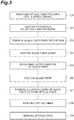
- FIG. 3 is a flowchart showing a method for manufacturing an optical fiber according to the embodiment.
- the method for manufacturing the optical fiber 110 includes: step S1 of inserting the optical fiber preform 101 into the heating furnace (wire drawing furnace) 103; step S2 of heating the tip portion 101b of the optical fiber preform 101; step S3 of drawing the glass fiber 104 from the tip portion 101b; step S4 of keeping the glass fiber 104 warm; step S5 of measuring the outer diameter of the glass fiber 104; step S6 of cooling the glass fiber 104; step S7 of forming a coating layer on the glass fiber 104 to form the optical fiber 110; step S8 of twisting the optical fiber 110; and step S9 of winding the optical fiber 110.
- the steps after step S4 are shown in the order when focusing on a certain point in the length direction of the optical fiber 110.
- step S1 the optical fiber preform 101 is inserted into the heating furnace 103 at a constant speed by the gripper 102.
- the tip portion 101b is fed into the heating furnace 103 through the opening 103a of the heating furnace 103 with the base end portion 101a gripped.
- step S2 the tip portion 101b is heated by the heating furnace 103 to be softened.
- step S3 the glass fiber 104 is drawn out through the opening 103b from the tip portion 101b softened by heating.
- the insertion speed of the optical fiber preform 101 in step S1 can be set according to the drawing speed of the glass fiber 104 in step S3.
- step S4 the drawn out glass fiber 104 is kept warm by the thermal insulation furnace 105. This relaxes the structure of the glass.
- step S5 the outer diameter of the glass fiber 104 is measured by the measuring instrument 106.
- step S6 the glass fiber 104 is cooled.
- step S7 first, the outer peripheral surface of the glass fiber 104 is coated with resin by the die 108 to form a coating resin. Subsequently, the coating resin is cured by ultraviolet rays irradiated from the ultraviolet irradiation device 109 to form a coating layer surrounding the glass fiber 104. As a result, a coating layer on the outer peripheral surface of the glass fiber 104 is formed. Accordingly, the optical fiber 110 is obtained.
- a plurality of coating layers may be formed by repeating step S7.
- step S8 the optical fiber 110 is twisted by the periodic swing of the swing guide roller 111.
- step S9 the optical fiber 110 is drawn at a predetermined speed and tension by the capstan 112 and then wound by the winder 113.
- FIG. 4 is a flowchart showing a step of controlling a swing of the swing guide roller.
- the method for manufacturing the optical fiber 110 further includes step S10 as shown in FIG. 4 .
- Step S10 is a step of controlling the swing of the swing guide roller 111 based on the outer diameter of the glass measured in step S5.
- Step S10 is performed by the controller 114.
- the controller 114 performs step S11 for obtaining the glass outer diameter.
- the controller 114 receives the glass outer diameter measured in step S5 from the measuring instrument 106.
- step S12 of storing the obtained outer diameter of the glass as a function of time.
- the controller 114 stores the outer diameter and the time in the memory in association with each other.
- step S13 for transforming the stored function into a function of frequency. This transform is performed by a Fourier transform.
- the controller 114 performs step S14 of identifying the first peak P1 caused by the first drawing condition and the second peak P2 caused by the second drawing condition in the transformed function of frequency.
- the first drawing condition is, for example, the frequency caused by a vibration of the manufacturing device 100, the building, or the optical fiber preform 101.
- the first drawing condition is the characteristic vibration frequency of the manufacturing device 100.
- the second drawing condition is a frequency caused by a disturbance such as a swing frequency of the swing guide roller 111.
- the first peak P1 has a relatively large bandwidth.
- the second peak P2 has a narrower bandwidth than the first peak P1.
- the controller 114 can identify the second peak P2 based on the swing frequency of the swing guide roller 111.
- the controller 114 can identify the first peak P1 by comparing the bandwidth of the second peak P2 with a bandwidth of a peak to be identified. The full width at half maximum may be used for the comparison instead of the bandwidth.
- step S15 of adjusting the second drawing condition so as to satisfy fn ⁇ fm - wm / 2 or fn > fm + wm / 2, where fm is the frequency of the first peak PI, wm is the full width at half maximum of the first peak PI, and fn is the frequency of the second peak P2. Since the second peak P2 corresponds to the swing frequency or the half multiple swing frequency of the swing guide roller 111, there is a plurality of second peaks P2. Therefore, the second drawing condition is adjusted so as to satisfy the above relation for the frequency fn of each of the plurality of the second peaks P2.
- the controller 114 adjusts the swing frequency of the swing guide roller 111 as the second drawing condition.
- the second peak P2 can be shifted from the first peak P1 so that the second peak P2 does not overlap the first peak P1.
- the second peak P2 overlapping the first peak P1 means that the frequency fn of the second peak P2 is within a frequency range centered on the frequency fm of the first peak P1 and having the same width as the full width at half maximum wm.
- the controller 114 performs step S10 to control the swing of the swing guide roller 111.
- the characteristic vibration frequency of the manufacturing device 100 also varies with the remaining length of the optical fiber preform 101. Therefore, even if the second peak P2 is once shifted from the first peak P1 by step S10, the first peak P1 may change to overlap the second peak P2 again. Therefore, it is effective to monitor the outer diameter of the glass at all times during the manufacturing the optical fiber 110, to repeatedly perform step S10, and to perform the feedback control of the second drawing condition.
- Step S10 may be performed, for example, every time step S5 is performed a predetermined number of times, or may be performed every predetermined time.
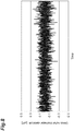
- FIG. 5 is a graph showing a temporal change in a glass outer diameter variation when the glass outer diameter variation deteriorated.
- the horizontal axis represents time
- the vertical axis represents the glass outer diameter variation ( ⁇ m).
- the glass outer diameter variation is the difference from the target glass outer diameter.
- the target glass outer diameter is set to 125 ⁇ m.
- 3 ⁇ of the glass outer diameter variation was 0.41 ⁇ m.
- FIG. 6 is a graph showing a frequency spectrum of a glass outer diameter variation when the glass outer diameter variation deteriorated.
- FIG. 6 shows the result of Fourier transform of the time variation of the glass outer diameter variation shown in FIG. 5 .
- the horizontal axis represents frequency and the vertical axis represents intensity.
- the first peak P1 is caused by the characteristic vibration frequency of the manufacturing device 100.
- the second peak P2 corresponds to the frequency of the swing guide roller 111, which imparts a twist, or a half multiple thereof.
- the first peak P1 overlaps one of the second peak P2.
- FIG. 7 is a graph showing a frequency spectrum of a glass outer diameter variation when feedback control was performed by the controller.
- the horizontal axis represents frequency and the vertical axis represents intensity.
- the frequency of the second peak P2 was adjusted so that the frequency of the second peak P2 was shifted from the frequency of the first peak P1.
- the swing frequency of the swing guide roller 111 becomes low, the frequency interval between the adjacent second peaks P2 becomes narrow, and then the second peak P2 easily overlaps the first peak P1. Therefore, in this embodiment, the swing frequency of the swing guide roller 111 was adjusted so as to increase.
- FIG. 8 is a graph showing a temporal change in a glass outer diameter variation when feedback control was performed by the controller.
- the horizontal axis represents time
- the vertical axis represents the glass outer diameter variation ( ⁇ m).
- 3 ⁇ of the glass outer diameter variation was improved to 0.22 ⁇ m. The drawing speed was not changed. Therefore, the productivity is maintained and the variation in the outer diameter of the glass is improved.
- step S10 the second drawing condition is adjusted so that the first peak P1 caused by the first drawing condition and the second peak P2 caused by the second drawing condition do not overlap each other.
- the occurrence of a large amplitude due to the overlap of the first peak P1 and the second peak P2 is suppressed. Therefore, it is possible to further suppress the deterioration of the variation of the glass outer diameter without deteriorating the productivity and the yield.
- the sampling time interval of the glass outer diameter by the measuring instrument 106 is 100 ms or less. Therefore, it is possible to surely detect the short-period variation of the glass outer diameter.
- the above-mentioned manufacturing method includes step S8 of forming a coating layer on the glass fiber 104 to form the optical fiber 110, and twisting the optical fiber 110 using the swing guide roller 111. Accordingly, since it is necessary to swing the swing guide roller 111 in order to twist the optical fiber 110, the swing frequency of the swing guide roller 111 becomes the second drawing condition. Therefore, the second peak P2 may be generated by the swing frequency. Therefore, step S10 which prevent the first peak P1 and the second peak P2 from overlapping each other is more effective.
Landscapes
- Chemical & Material Sciences (AREA)
- Engineering & Computer Science (AREA)
- Life Sciences & Earth Sciences (AREA)
- Geochemistry & Mineralogy (AREA)
- Materials Engineering (AREA)
- Organic Chemistry (AREA)
- General Life Sciences & Earth Sciences (AREA)
- Manufacturing & Machinery (AREA)
- Physics & Mathematics (AREA)
- Optics & Photonics (AREA)
- Chemical Kinetics & Catalysis (AREA)
- General Chemical & Material Sciences (AREA)
- General Physics & Mathematics (AREA)
- Thermal Sciences (AREA)
- Dispersion Chemistry (AREA)
- Manufacture, Treatment Of Glass Fibers (AREA)
- Optical Fibers, Optical Fiber Cores, And Optical Fiber Bundles (AREA)
Abstract
Description
- The present application is based upon and claims the benefit of the priority from
Japanese patent application No. 2020-117240, filed on July 7, 2020 - The present disclosure relates to a method for manufacturing an optical fiber.
- As one of the factors that deteriorate the variation of the glass outer diameter of the optical fiber, the vibration of the drawing tower is known.
Japanese Unexamined Patent Application Publication No. 2016 79073 - The present disclosure provides a method for manufacturing an optical fiber. The method includes: heating an optical fiber preform to draw glass fiber; measuring an outer diameter of the glass fiber to obtain a function of time; transforming the function of time into a function of frequency; identifying a first peak caused by a first drawing condition and a second peak caused by a second drawing condition in the function of frequency; and adjusting the second drawing condition so as to satisfy fn < fm - wm / 2 or fn > fm + wm / 2, where fm is a frequency of the first peak, wm is a full width at half maximum of the first peak, and fn is a frequency of the second peak.
- The foregoing and other purposes, aspects and advantages will be better understood from the following detailed description of a preferred embodiment of the invention with reference to the drawings, in which:
-
FIG. 1 is a configuration diagram of a manufacturing device used in the method for manufacturing an optical fiber according to an embodiment. -
FIG 2 is a diagram of a swing guide roller from the upstream side of the pass line. -
FIG. 3 is a flowchart showing a method for manufacturing an optical fiber according to the embodiment. -
FIG. 4 is a flowchart showing a step of controlling a swing of the swing guide roller. -
FIG. 5 is a graph showing a temporal change in a glass outer diameter variation when the glass outer diameter variation deteriorates. -
FIG. 6 is a graph showing a frequency spectrum of a glass outer diameter variation when the glass outer diameter variation deteriorates. -
FIG. 7 is a graph showing a frequency spectrum of a glass outer diameter variation when feedback control is performed by the controller. -
FIG. 8 is a graph showing a temporal change in a glass outer diameter variation when feedback control is performed by the controller. - One of the important characteristics of an optical fiber is polarization mode dispersion (PMD).
Japanese Unexamined Patent Application Publication No. 1996-295528 Japanese Unexamined Patent Application Publication No. 1996-295528 Japanese Unexamined Patent Application Publication No. 2016-79073 - An object of the present disclosure is to provide a method for manufacturing an optical fiber capable of further suppressing a variation in the outer diameter of glass without deteriorating productivity and yield.
- According to the present disclosure, it is possible to provide a method for manufacturing an optical fiber capable of further suppressing a variation in the outer diameter of glass without deteriorating productivity and yield.
- Embodiments of the present disclosure will be described. A method for manufacturing an optical fiber according to an embodiment of the present disclosure includes: heating an optical fiber preform to draw glass fiber; measuring an outer diameter of the glass fiber to obtain a function of time; transforming the function of time into a function of frequency; identifying a first peak caused by a first drawing condition and a second peak caused by a second drawing condition in the function of frequency; and adjusting the second drawing condition so as to satisfy fn < fm - wm / 2 or fn > fm + wm / 2, where fm is a frequency of the first peak, wm is a full width at half maximum of the first peak, and fn is a frequency of the second peak.
- In this method for manufacturing an optical fiber, the second drawing condition is adjusted so that the first peak caused by the first drawing condition and the second peak caused by the second drawing condition do not overlap each other. As a result, the occurrence of a large amplitude due to the overlap of the first peak and the second peak is suppressed. Therefore, it is possible to further suppress the deterioration of the variation of the glass outer diameter without deteriorating the productivity and the yield.
- A sampling time interval of the outer diameter may be 100 ms or less. In this case, it is possible to surely detect the short-period variation of the glass outer diameter.
- The method for manufacturing an optical fiber may further include forming a coating layer on the glass fiber to form an optical fiber; and twisting the optical fiber using a swing guide roller. In this case, since it is necessary to swing the swing guide roller in order to twist the optical fiber, the swing frequency of the swing guide roller may be the second drawing condition, and a second peak may be generated by the swing frequency. Therefore, it is more effective to prevent the first peak and the second peak from overlapping each other.
- The second drawing condition may be a swing frequency of the swing guide roller. In this case, by adjusting the swing frequency of the swing guide roller, it is possible to further suppress the deterioration of the variation of the glass outer diameter without deteriorating the productivity and the yield.
- A specific example of the method for manufacturing an optical fiber according to the present disclosure will be described below with reference to the drawings. The present invention is not limited by such examples but shown by the claims, and it is intended that all modifications within the meaning and scope of equivalents to the claims are embraced therein. In the following description, the same elements in a description of the drawings are denoted by the same reference signs and an overlapping description will be omitted.
-
FIG. 1 is a configuration diagram of a manufacturing device used in the method for manufacturing an optical fiber according to the embodiment. The manufacturing device 100 (drawing device) shown inFIG. 1 is a device for manufacturing theoptical fiber 110 from theoptical fiber preform 101 via theglass fiber 104. Amanufacturing device 100 is provided with agripper 102, aheating furnace 103, athermal insulation furnace 105, ameasuring instrument 106, acooler 107, adie 108, anultraviolet irradiation device 109, aswing guide roller 111, acapstan 112, awinder 113, and acontroller 114. - The
gripper 102 grips the optical fiber preform 101 and feeds it into theheating furnace 103 at a constant speed. Theoptical fiber preform 101 includes abase end portion 101a gripped by thegripper 102 and atip portion 101b inserted into theheating furnace 103. Thegripper 102 functions as a supplier for supplying the optical fiber preform 101 to theheating furnace 103. - The
heating furnace 103 includesopenings optical fiber preform 101 is inserted into the opening 103a. The opening 103b faces the opening 103a. Theglass fiber 104 is drawn out from the opening 103b. Theheating furnace 103 heats and softens thetip portion 101b of theoptical fiber preform 101 supplied into theheating furnace 103. Theglass fiber 104 is drawn out from thetip portion 101b softened by heating. Theglass fiber 104 is drawn out of theheating furnace 103 through the opening 103b. - The
thermal insulation furnace 105 keeps theglass fiber 104 warm and relaxes the structure of the glass. Themeasuring instrument 106 measures the outer diameter (glass outer diameter) of theglass fiber 104 in a state where the glass structure is relaxed. Themeasuring instrument 106 measures the outer diameter of the glass by irradiating theglass fiber 104 with a laser. The sampling time interval of the outer diameter of the glass by the measuringinstrument 106 is, for example, 100 ms or less. Depending on the drawing speed, there is a possibility that the variation of the short period of the glass outer diameter cannot be detected when the sampling interval becomes long. The measuringinstrument 106 transmits the measured outer diameter of the glass to thecontroller 114. - A cooler 107 is located after the measuring
instrument 106 to cool theglass fiber 104. Thedie 108 applies resin to the outer peripheral surface of theglass fiber 104 to form a coating resin. The resin includes an acrylate-based ultraviolet curable resin. Theultraviolet irradiation device 109 irradiates the coating resin formed on theglass fiber 104 with ultraviolet rays to cure the coating resin. As a result, the glass fiber is coated with the resin to form theoptical fiber 110. - The
swing guide roller 111 periodically tilts its axial direction to twist theoptical fiber 110. Theswing guide roller 111 is electrically connected to thecontroller 114, and is controlled and oscillated by thecontroller 114 to impart a twist to theoptical fiber 110. Although a pair of fixed guide rollers may be disposed in front of and behind theswing guide roller 111, it is not possible to completely prevent the swing of theswing guide roller 111 from being transmitted to other portions. -
FIG. 2 is a diagram of the swing guide roller as viewed from the upstream side of the pass line (the ultraviolet irradiation device side). As shown inFIG. 2 , theswing guide roller 111 swings within the range of ± θ in the angle formed by the rotation axis M1 and the predetermined axis M2. As a result of the swing motion as the swing, when the rotational axis M1 of theswing guide roller 111 is inclined by an angle + θ with respect to the predetermined axis M2, a lateral force is applied to theoptical fiber 110, and theoptical fiber 110 rolls on the surface of theswing guide roller 111 to twist theoptical fiber 110. When theswing guide roller 111 is inclined by an angle - θ with respect to a predetermined axis M2, theoptical fiber 110 is twisted in the opposite direction. - That is, the
optical fiber 110 is alternately twisted clockwise and counterclockwise with respect to the traveling direction (drawing direction) by repeating a symmetrical reciprocating motion in which theswing guide roller 111 swings at an angle ± θ with respect to a predetermined axis M2. Theswing guide roller 111 guides theoptical fiber 110 to thecapstan 112 while twisting theoptical fiber 110. - The
capstan 112 pulls theoptical fiber 110 at a predetermined speed and tension. Thewinder 113 winds theoptical fiber 110 drawn by thecapstan 112. Thecontroller 114 receives the glass outer diameter measured by the measuringinstrument 106 from the measuringinstrument 106, and feedback-controls the swing of theswing guide roller 111 based on the glass outer diameter. Thecontroller 114 may control theentire manufacturing device 100. - The
controller 114 may be configured as a computer system including, for example, a processor such as a CPU (Central Processing Unit), memories such as a RAM (Random Access Memory) and a ROM (Read Only Memory), input / output devices such as a touch panel, a mouse, a keyboard and a display, and a communication device such as a network card. Thecontroller 114 realizes the functions of thecontroller 114 by operating each hardware under the control of the processor based on the computer program stored in the memory. -
FIG. 3 is a flowchart showing a method for manufacturing an optical fiber according to the embodiment. The method for manufacturing theoptical fiber 110 includes: step S1 of inserting theoptical fiber preform 101 into the heating furnace (wire drawing furnace) 103; step S2 of heating thetip portion 101b of theoptical fiber preform 101; step S3 of drawing theglass fiber 104 from thetip portion 101b; step S4 of keeping theglass fiber 104 warm; step S5 of measuring the outer diameter of theglass fiber 104; step S6 of cooling theglass fiber 104; step S7 of forming a coating layer on theglass fiber 104 to form theoptical fiber 110; step S8 of twisting theoptical fiber 110; and step S9 of winding theoptical fiber 110. The steps after step S4 are shown in the order when focusing on a certain point in the length direction of theoptical fiber 110. - In step S1, the
optical fiber preform 101 is inserted into theheating furnace 103 at a constant speed by thegripper 102. In theoptical fiber preform 101, thetip portion 101b is fed into theheating furnace 103 through theopening 103a of theheating furnace 103 with thebase end portion 101a gripped. In step S2, thetip portion 101b is heated by theheating furnace 103 to be softened. - In step S3, the
glass fiber 104 is drawn out through theopening 103b from thetip portion 101b softened by heating. The insertion speed of theoptical fiber preform 101 in step S1 can be set according to the drawing speed of theglass fiber 104 in step S3. - In step S4, the drawn out
glass fiber 104 is kept warm by thethermal insulation furnace 105. This relaxes the structure of the glass. In step S5, the outer diameter of theglass fiber 104 is measured by the measuringinstrument 106. In step S6, theglass fiber 104 is cooled. - In step S7, first, the outer peripheral surface of the
glass fiber 104 is coated with resin by thedie 108 to form a coating resin. Subsequently, the coating resin is cured by ultraviolet rays irradiated from theultraviolet irradiation device 109 to form a coating layer surrounding theglass fiber 104. As a result, a coating layer on the outer peripheral surface of theglass fiber 104 is formed. Accordingly, theoptical fiber 110 is obtained. A plurality of coating layers may be formed by repeating step S7. - In step S8, the
optical fiber 110 is twisted by the periodic swing of theswing guide roller 111. In step S9, theoptical fiber 110 is drawn at a predetermined speed and tension by thecapstan 112 and then wound by thewinder 113. -
FIG. 4 is a flowchart showing a step of controlling a swing of the swing guide roller. The method for manufacturing theoptical fiber 110 further includes step S10 as shown inFIG. 4 . Step S10 is a step of controlling the swing of theswing guide roller 111 based on the outer diameter of the glass measured in step S5. Step S10 is performed by thecontroller 114. First, thecontroller 114 performs step S11 for obtaining the glass outer diameter. Specifically, thecontroller 114 receives the glass outer diameter measured in step S5 from the measuringinstrument 106. - Subsequently, the
controller 114 performs step S12 of storing the obtained outer diameter of the glass as a function of time. For example, thecontroller 114 stores the outer diameter and the time in the memory in association with each other. Subsequently, thecontroller 114 performs step S13 for transforming the stored function into a function of frequency. This transform is performed by a Fourier transform. - Subsequently, the
controller 114 performs step S14 of identifying the first peak P1 caused by the first drawing condition and the second peak P2 caused by the second drawing condition in the transformed function of frequency. The first drawing condition is, for example, the frequency caused by a vibration of themanufacturing device 100, the building, or theoptical fiber preform 101. Here, the first drawing condition is the characteristic vibration frequency of themanufacturing device 100. The second drawing condition is a frequency caused by a disturbance such as a swing frequency of theswing guide roller 111. The first peak P1 has a relatively large bandwidth. The second peak P2 has a narrower bandwidth than the first peak P1. - Since the second peak P2 is a peak corresponding to the swing frequency or the half multiple swing frequency of the
swing guide roller 111, thecontroller 114 can identify the second peak P2 based on the swing frequency of theswing guide roller 111. When the second peak P2 is identified, thecontroller 114 can identify the first peak P1 by comparing the bandwidth of the second peak P2 with a bandwidth of a peak to be identified. The full width at half maximum may be used for the comparison instead of the bandwidth. - Next, the
controller 114 performs step S15 of adjusting the second drawing condition so as to satisfy fn < fm - wm / 2 or fn > fm + wm / 2, where fm is the frequency of the first peak PI, wm is the full width at half maximum of the first peak PI, and fn is the frequency of the second peak P2. Since the second peak P2 corresponds to the swing frequency or the half multiple swing frequency of theswing guide roller 111, there is a plurality of second peaks P2. Therefore, the second drawing condition is adjusted so as to satisfy the above relation for the frequency fn of each of the plurality of the second peaks P2. - In this embodiment, the
controller 114 adjusts the swing frequency of theswing guide roller 111 as the second drawing condition. Thus, the second peak P2 can be shifted from the first peak P1 so that the second peak P2 does not overlap the first peak P1. As a result, it is suppressed that the first peak P1 and the second peak P2 are overlapped each other, and that the amplitude of the glass outer diameter variation increases. The second peak P2 overlapping the first peak P1 means that the frequency fn of the second peak P2 is within a frequency range centered on the frequency fm of the first peak P1 and having the same width as the full width at half maximum wm. - As described above, the
controller 114 performs step S10 to control the swing of theswing guide roller 111. The characteristic vibration frequency of themanufacturing device 100 also varies with the remaining length of theoptical fiber preform 101. Therefore, even if the second peak P2 is once shifted from the first peak P1 by step S10, the first peak P1 may change to overlap the second peak P2 again. Therefore, it is effective to monitor the outer diameter of the glass at all times during the manufacturing theoptical fiber 110, to repeatedly perform step S10, and to perform the feedback control of the second drawing condition. Step S10 may be performed, for example, every time step S5 is performed a predetermined number of times, or may be performed every predetermined time. -
FIG. 5 is a graph showing a temporal change in a glass outer diameter variation when the glass outer diameter variation deteriorated. InFIG. 5 , the horizontal axis represents time, and the vertical axis represents the glass outer diameter variation (µm). The glass outer diameter variation is the difference from the target glass outer diameter. In a general optical fiber, the target glass outer diameter is set to 125 µm. In the graph ofFIG. 5 , 3σ of the glass outer diameter variation was 0.41 µm. -
FIG. 6 is a graph showing a frequency spectrum of a glass outer diameter variation when the glass outer diameter variation deteriorated. -
FIG. 6 shows the result of Fourier transform of the time variation of the glass outer diameter variation shown inFIG. 5 . InFIG. 6 , the horizontal axis represents frequency and the vertical axis represents intensity. In the frequency spectrum shown inFIG. 6 , there are a first peak P1 having a relatively wide bandwidth and a second peak P2 having a relatively narrow bandwidth. As described above, the first peak P1 is caused by the characteristic vibration frequency of themanufacturing device 100. The second peak P2 corresponds to the frequency of theswing guide roller 111, which imparts a twist, or a half multiple thereof. Here, the first peak P1 overlaps one of the second peak P2. When the first peak P1 and the second peak P2 overlap with each other in this way, the amplitude of the glass outer diameter variation increases. - Feedback control was performed by the
controller 114.FIG. 7 is a graph showing a frequency spectrum of a glass outer diameter variation when feedback control was performed by the controller. InFIG. 7 , the horizontal axis represents frequency and the vertical axis represents intensity. Specifically, the frequency of the second peak P2 was adjusted so that the frequency of the second peak P2 was shifted from the frequency of the first peak P1. When the swing frequency of theswing guide roller 111 becomes low, the frequency interval between the adjacent second peaks P2 becomes narrow, and then the second peak P2 easily overlaps the first peak P1. Therefore, in this embodiment, the swing frequency of theswing guide roller 111 was adjusted so as to increase. -
FIG. 8 is a graph showing a temporal change in a glass outer diameter variation when feedback control was performed by the controller. InFIG. 8 , the horizontal axis represents time, and the vertical axis represents the glass outer diameter variation (µm). In the graph ofFIG. 8 , 3σ of the glass outer diameter variation was improved to 0.22 µm. The drawing speed was not changed. Therefore, the productivity is maintained and the variation in the outer diameter of the glass is improved. - As described above, in the manufacturing method according to the embodiment, in step S10, the second drawing condition is adjusted so that the first peak P1 caused by the first drawing condition and the second peak P2 caused by the second drawing condition do not overlap each other. As a result, the occurrence of a large amplitude due to the overlap of the first peak P1 and the second peak P2 is suppressed. Therefore, it is possible to further suppress the deterioration of the variation of the glass outer diameter without deteriorating the productivity and the yield.
- The sampling time interval of the glass outer diameter by the measuring
instrument 106 is 100 ms or less. Therefore, it is possible to surely detect the short-period variation of the glass outer diameter. - The above-mentioned manufacturing method includes step S8 of forming a coating layer on the
glass fiber 104 to form theoptical fiber 110, and twisting theoptical fiber 110 using theswing guide roller 111. Accordingly, since it is necessary to swing theswing guide roller 111 in order to twist theoptical fiber 110, the swing frequency of theswing guide roller 111 becomes the second drawing condition. Therefore, the second peak P2 may be generated by the swing frequency. Therefore, step S10 which prevent the first peak P1 and the second peak P2 from overlapping each other is more effective.
Claims (7)
- A method for manufacturing an optical fiber comprising:heating an optical fiber preform to draw glass fiber;measuring an outer diameter of the glass fiber to obtain a function of time;transforming the function of time into a function of frequency;identifying a first peak caused by a first drawing condition and a second peak caused by a second drawing condition in the function of frequency; andadjusting the second drawing condition so as to satisfy fn < fm - wm / 2 or fn > fm + wm / 2, where fm is a frequency of the first peak, wm is a full width at half maximum of the first peak, and fn is a frequency of the second peak.
- The method for manufacturing an optical fiber according to claim 1,
wherein a sampling time interval of the outer diameter is 100 ms or less. - The method for manufacturing an optical fiber according to claim 1 or 2, further comprising:forming a coating layer on the glass fiber to form an optical fiber; andtwisting the optical fiber using a swing guide roller.
- The method for manufacturing an optical fiber according to claim 3,
wherein the second drawing condition is a swing frequency of the swing guide roller. - The method for manufacturing an optical fiber according to claim 3,
wherein the second peak includes a plurality of second peaks corresponding to a swing frequency or a half multiple swing frequency of the swing guide roller, and
the second drawing condition is adjusted so as to satisfy fn < fm - wm / 2 or fn > fm+ wm / 2 for the frequency fn of each of the plurality of second peaks. - The method for manufacturing an optical fiber according to claim 1,
wherein the first drawing condition is a characteristic vibration frequency of a manufacturing device. - The method for manufacturing an optical fiber according to claim 1,
a bandwidth of the first peak is wider than a bandwidth of the second peak.
Applications Claiming Priority (1)
| Application Number | Priority Date | Filing Date | Title |
|---|---|---|---|
| JP2020117240A JP7501171B2 (en) | 2020-07-07 | 2020-07-07 | Optical fiber manufacturing method |
Publications (2)
| Publication Number | Publication Date |
|---|---|
| EP3936483A1 true EP3936483A1 (en) | 2022-01-12 |
| EP3936483B1 EP3936483B1 (en) | 2024-09-25 |
Family
ID=76601066
Family Applications (1)
| Application Number | Title | Priority Date | Filing Date |
|---|---|---|---|
| EP21181416.5A Active EP3936483B1 (en) | 2020-07-07 | 2021-06-24 | Method for manufacturing optical fiber |
Country Status (5)
| Country | Link |
|---|---|
| US (1) | US20220009817A1 (en) |
| EP (1) | EP3936483B1 (en) |
| JP (1) | JP7501171B2 (en) |
| CN (1) | CN113912283B (en) |
| DK (1) | DK3936483T3 (en) |
Citations (3)
| Publication number | Priority date | Publication date | Assignee | Title |
|---|---|---|---|---|
| JPH08295528A (en) | 1995-03-01 | 1996-11-12 | Sumitomo Electric Ind Ltd | Optical fiber and method of manufacturing optical fiber |
| JP2010120811A (en) * | 2008-11-19 | 2010-06-03 | Fujikura Ltd | Method and apparatus for producing optical fiber strand |
| JP2016079073A (en) | 2014-10-20 | 2016-05-16 | 住友電気工業株式会社 | Apparatus and method for drawing optical fiber |
Family Cites Families (14)
| Publication number | Priority date | Publication date | Assignee | Title |
|---|---|---|---|---|
| US5314517A (en) * | 1992-12-31 | 1994-05-24 | Corning Incorporated | Method controlling the draw rate in the drawing of a glass feedstock |
| JP3353805B2 (en) * | 1996-03-14 | 2002-12-03 | 住友電気工業株式会社 | Optical fiber drawing equipment |
| US6076376A (en) * | 1995-03-01 | 2000-06-20 | Sumitomo Electric Industries, Ltd. | Method of making an optical fiber having an imparted twist |
| JP3777627B2 (en) * | 1995-04-03 | 2006-05-24 | 住友電気工業株式会社 | Glass fiber manufacturing method and manufacturing apparatus |
| JP3675903B2 (en) * | 1995-09-12 | 2005-07-27 | 古河電気工業株式会社 | Optical fiber drawing method and apparatus |
| JPH10316446A (en) * | 1997-03-18 | 1998-12-02 | Furukawa Electric Co Ltd:The | Optical fiber drawing tension measuring method |
| JP3070603B2 (en) * | 1998-09-24 | 2000-07-31 | 住友電気工業株式会社 | Manufacturing method of optical fiber |
| AU761479B2 (en) * | 1999-01-27 | 2003-06-05 | Sumitomo Electric Industries, Ltd. | Method and device for producing covered optical fiber and covered optical fiber |
| JP2003513267A (en) * | 1999-10-29 | 2003-04-08 | ピレリー・カビ・エ・システミ・ソチエタ・ペル・アツィオーニ | Method for measuring the twist imparted to an optical fiber and procedure for treating the optical fiber using this method |
| JP3983597B2 (en) | 2002-05-13 | 2007-09-26 | 株式会社フジクラ | Optical fiber manufacturing method |
| KR100401342B1 (en) * | 2002-08-31 | 2003-10-10 | Lg Cable Ltd | Apparatus for spinning optical fiber and apparatus and method for fabricating optical fiber using the same |
| JP4930107B2 (en) * | 2007-03-06 | 2012-05-16 | 住友電気工業株式会社 | PMD characteristic measurement method of optical fiber, drawing method, method of identifying an abnormal part, optical fiber transmission line construction method |
| JP6268977B2 (en) * | 2013-11-25 | 2018-01-31 | 住友電気工業株式会社 | Manufacturing method of bent optical fiber |
| CN104973774B (en) * | 2014-04-02 | 2019-08-30 | 住友电气工业株式会社 | Optical fiber manufacturing method and manufacturing device |
-
2020
- 2020-07-07 JP JP2020117240A patent/JP7501171B2/en active Active
-
2021
- 2021-06-22 CN CN202110690286.0A patent/CN113912283B/en active Active
- 2021-06-24 DK DK21181416.5T patent/DK3936483T3/en active
- 2021-06-24 EP EP21181416.5A patent/EP3936483B1/en active Active
- 2021-06-29 US US17/361,421 patent/US20220009817A1/en not_active Abandoned
Patent Citations (4)
| Publication number | Priority date | Publication date | Assignee | Title |
|---|---|---|---|---|
| JPH08295528A (en) | 1995-03-01 | 1996-11-12 | Sumitomo Electric Ind Ltd | Optical fiber and method of manufacturing optical fiber |
| JP2010120811A (en) * | 2008-11-19 | 2010-06-03 | Fujikura Ltd | Method and apparatus for producing optical fiber strand |
| JP2016079073A (en) | 2014-10-20 | 2016-05-16 | 住友電気工業株式会社 | Apparatus and method for drawing optical fiber |
| JP6515483B2 (en) * | 2014-10-20 | 2019-05-22 | 住友電気工業株式会社 | Optical fiber drawing apparatus and optical fiber drawing method |
Also Published As
| Publication number | Publication date |
|---|---|
| US20220009817A1 (en) | 2022-01-13 |
| CN113912283B (en) | 2025-11-04 |
| CN113912283A (en) | 2022-01-11 |
| DK3936483T3 (en) | 2024-10-14 |
| JP7501171B2 (en) | 2024-06-18 |
| EP3936483B1 (en) | 2024-09-25 |
| JP2022014725A (en) | 2022-01-20 |
Similar Documents
| Publication | Publication Date | Title |
|---|---|---|
| JP3557606B2 (en) | Optical fiber and method of manufacturing optical fiber | |
| US6837074B2 (en) | Method of measuring the twist imparted to an optical fibre and procedure for processing an optical fibre using this method | |
| US6347537B1 (en) | Method of drawing a twisted optical fiber | |
| US20010020374A1 (en) | Method and apparatus for manufacturing an optical fiber from a preform | |
| KR20030045885A (en) | Apparatus for low polarization mode dispersion | |
| CN100414326C (en) | Apparatus for imparting spin to optical fiber and optical fiber manufacturing method and apparatus therefor | |
| US20110314873A1 (en) | Method of manufacturing optical fiber | |
| US20150285994A1 (en) | Manufacturing method and manufacturing apparatus of optical fiber | |
| EP0795521A1 (en) | Method and apparatus for drawing an optical fiber of reduced polarisation mode dispersion from a preform | |
| EP4305481A1 (en) | System and method of controlling a strander by wireless visual monitoring of a subunit reel | |
| EP3936483B1 (en) | Method for manufacturing optical fiber | |
| EP1105355A1 (en) | Method and apparatus for twisting a coated optical fiber during drawing from a preform | |
| KR100416970B1 (en) | Spin device for low polarization mode dispersion of optical fiber | |
| US6789399B1 (en) | Method for measuring the twisting of an optical fiber, and a method and apparatus for manufacturing optical fibers | |
| WO2002063354A1 (en) | Method and apparatus for manufacturing optical fiber | |
| US20030079501A1 (en) | Method of drawing multi-line optical fiber | |
| JP2004175611A (en) | Method and apparatus for manufacturing optical fiber | |
| EP1327614A1 (en) | Device/method to improve coating diameter and uniformity with adjustable sizing die | |
| US7263263B2 (en) | Method for monitoring spin imparted on optical fiber and method for making optical fiber by using the same | |
| JP3085953B1 (en) | Method and apparatus for manufacturing optical fiber | |
| CN120736793B (en) | A method and apparatus for manufacturing low polarization mode dispersion hollow-core optical fiber | |
| US20240053535A1 (en) | Method for manufacturing optical fiber and optical fiber | |
| CN112279499B (en) | Method and apparatus for controlling glass ribbon stress | |
| JP2004161572A (en) | Optical fiber winding method and optical fiber coil | |
| JP2001264605A (en) | Optical fiber ribbon manufacturing equipment |
Legal Events
| Date | Code | Title | Description |
|---|---|---|---|
| PUAI | Public reference made under article 153(3) epc to a published international application that has entered the european phase |
Free format text: ORIGINAL CODE: 0009012 |
|
| STAA | Information on the status of an ep patent application or granted ep patent |
Free format text: STATUS: THE APPLICATION HAS BEEN PUBLISHED |
|
| AK | Designated contracting states |
Kind code of ref document: A1 Designated state(s): AL AT BE BG CH CY CZ DE DK EE ES FI FR GB GR HR HU IE IS IT LI LT LU LV MC MK MT NL NO PL PT RO RS SE SI SK SM TR |
|
| B565 | Issuance of search results under rule 164(2) epc |
Effective date: 20211123 |
|
| STAA | Information on the status of an ep patent application or granted ep patent |
Free format text: STATUS: REQUEST FOR EXAMINATION WAS MADE |
|
| 17P | Request for examination filed |
Effective date: 20220627 |
|
| RBV | Designated contracting states (corrected) |
Designated state(s): AL AT BE BG CH CY CZ DE DK EE ES FI FR GB GR HR HU IE IS IT LI LT LU LV MC MK MT NL NO PL PT RO RS SE SI SK SM TR |
|
| GRAP | Despatch of communication of intention to grant a patent |
Free format text: ORIGINAL CODE: EPIDOSNIGR1 |
|
| STAA | Information on the status of an ep patent application or granted ep patent |
Free format text: STATUS: GRANT OF PATENT IS INTENDED |
|
| INTG | Intention to grant announced |
Effective date: 20240607 |
|
| GRAS | Grant fee paid |
Free format text: ORIGINAL CODE: EPIDOSNIGR3 |
|
| GRAA | (expected) grant |
Free format text: ORIGINAL CODE: 0009210 |
|
| STAA | Information on the status of an ep patent application or granted ep patent |
Free format text: STATUS: THE PATENT HAS BEEN GRANTED |
|
| P01 | Opt-out of the competence of the unified patent court (upc) registered |
Free format text: CASE NUMBER: APP_44637/2024 Effective date: 20240731 |
|
| AK | Designated contracting states |
Kind code of ref document: B1 Designated state(s): AL AT BE BG CH CY CZ DE DK EE ES FI FR GB GR HR HU IE IS IT LI LT LU LV MC MK MT NL NO PL PT RO RS SE SI SK SM TR |
|
| REG | Reference to a national code |
Ref country code: GB Ref legal event code: FG4D |
|
| REG | Reference to a national code |
Ref country code: CH Ref legal event code: EP |
|
| REG | Reference to a national code |
Ref country code: DK Ref legal event code: T3 Effective date: 20241007 |
|
| REG | Reference to a national code |
Ref country code: DE Ref legal event code: R096 Ref document number: 602021019187 Country of ref document: DE |
|
| REG | Reference to a national code |
Ref country code: IE Ref legal event code: FG4D |
|
| REG | Reference to a national code |
Ref country code: LT Ref legal event code: MG9D |
|
| PG25 | Lapsed in a contracting state [announced via postgrant information from national office to epo] |
Ref country code: GR Free format text: LAPSE BECAUSE OF FAILURE TO SUBMIT A TRANSLATION OF THE DESCRIPTION OR TO PAY THE FEE WITHIN THE PRESCRIBED TIME-LIMIT Effective date: 20241226 Ref country code: FI Free format text: LAPSE BECAUSE OF FAILURE TO SUBMIT A TRANSLATION OF THE DESCRIPTION OR TO PAY THE FEE WITHIN THE PRESCRIBED TIME-LIMIT Effective date: 20240925 |
|
| PG25 | Lapsed in a contracting state [announced via postgrant information from national office to epo] |
Ref country code: BG Free format text: LAPSE BECAUSE OF FAILURE TO SUBMIT A TRANSLATION OF THE DESCRIPTION OR TO PAY THE FEE WITHIN THE PRESCRIBED TIME-LIMIT Effective date: 20240925 |
|
| PG25 | Lapsed in a contracting state [announced via postgrant information from national office to epo] |
Ref country code: LV Free format text: LAPSE BECAUSE OF FAILURE TO SUBMIT A TRANSLATION OF THE DESCRIPTION OR TO PAY THE FEE WITHIN THE PRESCRIBED TIME-LIMIT Effective date: 20240925 |
|
| PG25 | Lapsed in a contracting state [announced via postgrant information from national office to epo] |
Ref country code: RS Free format text: LAPSE BECAUSE OF FAILURE TO SUBMIT A TRANSLATION OF THE DESCRIPTION OR TO PAY THE FEE WITHIN THE PRESCRIBED TIME-LIMIT Effective date: 20241225 |
|
| REG | Reference to a national code |
Ref country code: NL Ref legal event code: MP Effective date: 20240925 |
|
| PG25 | Lapsed in a contracting state [announced via postgrant information from national office to epo] |
Ref country code: RS Free format text: LAPSE BECAUSE OF FAILURE TO SUBMIT A TRANSLATION OF THE DESCRIPTION OR TO PAY THE FEE WITHIN THE PRESCRIBED TIME-LIMIT Effective date: 20241225 Ref country code: LV Free format text: LAPSE BECAUSE OF FAILURE TO SUBMIT A TRANSLATION OF THE DESCRIPTION OR TO PAY THE FEE WITHIN THE PRESCRIBED TIME-LIMIT Effective date: 20240925 Ref country code: GR Free format text: LAPSE BECAUSE OF FAILURE TO SUBMIT A TRANSLATION OF THE DESCRIPTION OR TO PAY THE FEE WITHIN THE PRESCRIBED TIME-LIMIT Effective date: 20241226 Ref country code: FI Free format text: LAPSE BECAUSE OF FAILURE TO SUBMIT A TRANSLATION OF THE DESCRIPTION OR TO PAY THE FEE WITHIN THE PRESCRIBED TIME-LIMIT Effective date: 20240925 Ref country code: BG Free format text: LAPSE BECAUSE OF FAILURE TO SUBMIT A TRANSLATION OF THE DESCRIPTION OR TO PAY THE FEE WITHIN THE PRESCRIBED TIME-LIMIT Effective date: 20240925 |
|
| REG | Reference to a national code |
Ref country code: AT Ref legal event code: MK05 Ref document number: 1726551 Country of ref document: AT Kind code of ref document: T Effective date: 20240925 |
|
| PG25 | Lapsed in a contracting state [announced via postgrant information from national office to epo] |
Ref country code: NL Free format text: LAPSE BECAUSE OF FAILURE TO SUBMIT A TRANSLATION OF THE DESCRIPTION OR TO PAY THE FEE WITHIN THE PRESCRIBED TIME-LIMIT Effective date: 20240925 |
|
| PG25 | Lapsed in a contracting state [announced via postgrant information from national office to epo] |
Ref country code: PT Free format text: LAPSE BECAUSE OF FAILURE TO SUBMIT A TRANSLATION OF THE DESCRIPTION OR TO PAY THE FEE WITHIN THE PRESCRIBED TIME-LIMIT Effective date: 20250127 Ref country code: IS Free format text: LAPSE BECAUSE OF FAILURE TO SUBMIT A TRANSLATION OF THE DESCRIPTION OR TO PAY THE FEE WITHIN THE PRESCRIBED TIME-LIMIT Effective date: 20250125 |
|
| PG25 | Lapsed in a contracting state [announced via postgrant information from national office to epo] |
Ref country code: RO Free format text: LAPSE BECAUSE OF FAILURE TO SUBMIT A TRANSLATION OF THE DESCRIPTION OR TO PAY THE FEE WITHIN THE PRESCRIBED TIME-LIMIT Effective date: 20240925 Ref country code: SM Free format text: LAPSE BECAUSE OF FAILURE TO SUBMIT A TRANSLATION OF THE DESCRIPTION OR TO PAY THE FEE WITHIN THE PRESCRIBED TIME-LIMIT Effective date: 20240925 |
|
| PG25 | Lapsed in a contracting state [announced via postgrant information from national office to epo] |
Ref country code: ES Free format text: LAPSE BECAUSE OF FAILURE TO SUBMIT A TRANSLATION OF THE DESCRIPTION OR TO PAY THE FEE WITHIN THE PRESCRIBED TIME-LIMIT Effective date: 20240925 |
|
| PG25 | Lapsed in a contracting state [announced via postgrant information from national office to epo] |
Ref country code: AT Free format text: LAPSE BECAUSE OF FAILURE TO SUBMIT A TRANSLATION OF THE DESCRIPTION OR TO PAY THE FEE WITHIN THE PRESCRIBED TIME-LIMIT Effective date: 20240925 Ref country code: EE Free format text: LAPSE BECAUSE OF FAILURE TO SUBMIT A TRANSLATION OF THE DESCRIPTION OR TO PAY THE FEE WITHIN THE PRESCRIBED TIME-LIMIT Effective date: 20240925 |
|
| PG25 | Lapsed in a contracting state [announced via postgrant information from national office to epo] |
Ref country code: PL Free format text: LAPSE BECAUSE OF FAILURE TO SUBMIT A TRANSLATION OF THE DESCRIPTION OR TO PAY THE FEE WITHIN THE PRESCRIBED TIME-LIMIT Effective date: 20240925 Ref country code: CZ Free format text: LAPSE BECAUSE OF FAILURE TO SUBMIT A TRANSLATION OF THE DESCRIPTION OR TO PAY THE FEE WITHIN THE PRESCRIBED TIME-LIMIT Effective date: 20240925 |
|
| PG25 | Lapsed in a contracting state [announced via postgrant information from national office to epo] |
Ref country code: IT Free format text: LAPSE BECAUSE OF FAILURE TO SUBMIT A TRANSLATION OF THE DESCRIPTION OR TO PAY THE FEE WITHIN THE PRESCRIBED TIME-LIMIT Effective date: 20240925 Ref country code: SK Free format text: LAPSE BECAUSE OF FAILURE TO SUBMIT A TRANSLATION OF THE DESCRIPTION OR TO PAY THE FEE WITHIN THE PRESCRIBED TIME-LIMIT Effective date: 20240925 |
|
| REG | Reference to a national code |
Ref country code: DE Ref legal event code: R097 Ref document number: 602021019187 Country of ref document: DE |
|
| PGFP | Annual fee paid to national office [announced via postgrant information from national office to epo] |
Ref country code: GB Payment date: 20250501 Year of fee payment: 5 Ref country code: DK Payment date: 20250618 Year of fee payment: 5 |
|
| PGFP | Annual fee paid to national office [announced via postgrant information from national office to epo] |
Ref country code: NO Payment date: 20250610 Year of fee payment: 5 |
|
| PGFP | Annual fee paid to national office [announced via postgrant information from national office to epo] |
Ref country code: FR Payment date: 20250508 Year of fee payment: 5 |
|
| PLBE | No opposition filed within time limit |
Free format text: ORIGINAL CODE: 0009261 |
|
| STAA | Information on the status of an ep patent application or granted ep patent |
Free format text: STATUS: NO OPPOSITION FILED WITHIN TIME LIMIT |
|
| 26N | No opposition filed |
Effective date: 20250626 |
|
| PG25 | Lapsed in a contracting state [announced via postgrant information from national office to epo] |
Ref country code: SE Free format text: LAPSE BECAUSE OF FAILURE TO SUBMIT A TRANSLATION OF THE DESCRIPTION OR TO PAY THE FEE WITHIN THE PRESCRIBED TIME-LIMIT Effective date: 20240925 |
|
| REG | Reference to a national code |
Ref country code: DE Ref legal event code: R119 Ref document number: 602021019187 Country of ref document: DE |
|
| PG25 | Lapsed in a contracting state [announced via postgrant information from national office to epo] |
Ref country code: HR Free format text: LAPSE BECAUSE OF FAILURE TO SUBMIT A TRANSLATION OF THE DESCRIPTION OR TO PAY THE FEE WITHIN THE PRESCRIBED TIME-LIMIT Effective date: 20240925 |
|
| REG | Reference to a national code |
Ref country code: CH Ref legal event code: H13 Free format text: ST27 STATUS EVENT CODE: U-0-0-H10-H13 (AS PROVIDED BY THE NATIONAL OFFICE) Effective date: 20260127 |
|
| PG25 | Lapsed in a contracting state [announced via postgrant information from national office to epo] |
Ref country code: MC Free format text: LAPSE BECAUSE OF FAILURE TO SUBMIT A TRANSLATION OF THE DESCRIPTION OR TO PAY THE FEE WITHIN THE PRESCRIBED TIME-LIMIT Effective date: 20240925 |
|
| PG25 | Lapsed in a contracting state [announced via postgrant information from national office to epo] |
Ref country code: LU Free format text: LAPSE BECAUSE OF NON-PAYMENT OF DUE FEES Effective date: 20250624 |
|
| REG | Reference to a national code |
Ref country code: BE Ref legal event code: MM Effective date: 20250630 |
|
| PG25 | Lapsed in a contracting state [announced via postgrant information from national office to epo] |
Ref country code: DE Free format text: LAPSE BECAUSE OF NON-PAYMENT OF DUE FEES Effective date: 20260101 Ref country code: IE Free format text: LAPSE BECAUSE OF NON-PAYMENT OF DUE FEES Effective date: 20250624 |
|
| PG25 | Lapsed in a contracting state [announced via postgrant information from national office to epo] |
Ref country code: BE Free format text: LAPSE BECAUSE OF NON-PAYMENT OF DUE FEES Effective date: 20250630 |
|
| PG25 | Lapsed in a contracting state [announced via postgrant information from national office to epo] |
Ref country code: CH Free format text: LAPSE BECAUSE OF NON-PAYMENT OF DUE FEES Effective date: 20250630 |