EP3936444A1 - A label-rejecting station - Google Patents
A label-rejecting station Download PDFInfo
- Publication number
- EP3936444A1 EP3936444A1 EP21182728.2A EP21182728A EP3936444A1 EP 3936444 A1 EP3936444 A1 EP 3936444A1 EP 21182728 A EP21182728 A EP 21182728A EP 3936444 A1 EP3936444 A1 EP 3936444A1
- Authority
- EP
- European Patent Office
- Prior art keywords
- label
- support band
- deviator
- rejecting station
- band
- Prior art date
- Legal status (The legal status is an assumption and is not a legal conclusion. Google has not performed a legal analysis and makes no representation as to the accuracy of the status listed.)
- Granted
Links
Images

Classifications
-
- B—PERFORMING OPERATIONS; TRANSPORTING
- B65—CONVEYING; PACKING; STORING; HANDLING THIN OR FILAMENTARY MATERIAL
- B65C—LABELLING OR TAGGING MACHINES, APPARATUS, OR PROCESSES
- B65C9/00—Details of labelling machines or apparatus
- B65C9/40—Controls; Safety devices
-
- B—PERFORMING OPERATIONS; TRANSPORTING
- B65—CONVEYING; PACKING; STORING; HANDLING THIN OR FILAMENTARY MATERIAL
- B65C—LABELLING OR TAGGING MACHINES, APPARATUS, OR PROCESSES
- B65C9/00—Details of labelling machines or apparatus
- B65C9/0006—Removing backing sheets
-
- B—PERFORMING OPERATIONS; TRANSPORTING
- B65—CONVEYING; PACKING; STORING; HANDLING THIN OR FILAMENTARY MATERIAL
- B65C—LABELLING OR TAGGING MACHINES, APPARATUS, OR PROCESSES
- B65C9/00—Details of labelling machines or apparatus
- B65C9/08—Label feeding
- B65C9/18—Label feeding from strips, e.g. from rolls
-
- B—PERFORMING OPERATIONS; TRANSPORTING
- B65—CONVEYING; PACKING; STORING; HANDLING THIN OR FILAMENTARY MATERIAL
- B65C—LABELLING OR TAGGING MACHINES, APPARATUS, OR PROCESSES
- B65C9/00—Details of labelling machines or apparatus
- B65C9/08—Label feeding
-
- B—PERFORMING OPERATIONS; TRANSPORTING
- B65—CONVEYING; PACKING; STORING; HANDLING THIN OR FILAMENTARY MATERIAL
- B65C—LABELLING OR TAGGING MACHINES, APPARATUS, OR PROCESSES
- B65C9/00—Details of labelling machines or apparatus
- B65C9/08—Label feeding
- B65C9/18—Label feeding from strips, e.g. from rolls
- B65C9/1865—Label feeding from strips, e.g. from rolls the labels adhering on a backing strip
-
- B—PERFORMING OPERATIONS; TRANSPORTING
- B65—CONVEYING; PACKING; STORING; HANDLING THIN OR FILAMENTARY MATERIAL
- B65C—LABELLING OR TAGGING MACHINES, APPARATUS, OR PROCESSES
- B65C9/00—Details of labelling machines or apparatus
- B65C9/26—Devices for applying labels
-
- B—PERFORMING OPERATIONS; TRANSPORTING
- B65—CONVEYING; PACKING; STORING; HANDLING THIN OR FILAMENTARY MATERIAL
- B65C—LABELLING OR TAGGING MACHINES, APPARATUS, OR PROCESSES
- B65C9/00—Details of labelling machines or apparatus
- B65C9/40—Controls; Safety devices
- B65C9/42—Label feed control
-
- B—PERFORMING OPERATIONS; TRANSPORTING
- B65—CONVEYING; PACKING; STORING; HANDLING THIN OR FILAMENTARY MATERIAL
- B65C—LABELLING OR TAGGING MACHINES, APPARATUS, OR PROCESSES
- B65C9/00—Details of labelling machines or apparatus
- B65C9/0006—Removing backing sheets
- B65C2009/0009—Removing backing sheets by means of a peeling tip
-
- B—PERFORMING OPERATIONS; TRANSPORTING
- B65—CONVEYING; PACKING; STORING; HANDLING THIN OR FILAMENTARY MATERIAL
- B65C—LABELLING OR TAGGING MACHINES, APPARATUS, OR PROCESSES
- B65C9/00—Details of labelling machines or apparatus
- B65C9/40—Controls; Safety devices
- B65C2009/402—Controls; Safety devices for detecting properties or defects of labels
- B65C2009/404—Controls; Safety devices for detecting properties or defects of labels prior to labelling
Definitions
- the present invention relates to a station for rejecting labels, which can be used in a labelling machine.
- Labelling machines for example in the pharmaceutical sector, are used to apply - on various types of articles, for example, containers such as vials or bottles - relative self-adhesive labels that contain information printed on them (identification code/bar code of the article, contents and/or its expiration date, etc.).
- a labelling machine in general, comprises, in succession: a station for feeding the labels, wherein the labels to be applied to the articles are fed, supported by a band, along an advancing path; a control station and a label-rejection station where, respectively, the compliance of the labels is checked and any non-compliant labels are discarded. Finally, a station for applying the labels is provided, arranged at the end of the advancing path, where the labels are applied to the respective articles.
- the control station comprises a control system generally of the optical type.
- a label In the event that a label is compliant, it proceeds along the advancing path until it reaches the application station, where it is applied to a respective article. If, on the other hand, the control system detects the non-conformity of a label, the label must be discarded to prevent it from being applied incorrectly on an item.
- the label-rejecting station comprises a deviator and detachment element, which is arranged along the advancing path, and is activated to deviate the support band of the labels at the label to be rejected.
- the deviation angle of the band of the labels must be large enough to ensure the detachment of the label from the band itself, or rather, its lifting with respect to the band. Therefore, the deviator and detachment element usually acts along a direction perpendicular to the advancing path of the band, to divert its path.
- the rejecting station further comprises a roller for collecting the rejected labels, arranged to intercept a label that is lifted from the support band by the deviator and detachment element, thus attaching itself to the collection roller itself.
- the deviation of the path of the support band involves a decrease in the tensioning of the support band itself, which is carried to travel a significantly longer path than the path taken in the event of compliant labels.
- This loss, even partial, of tension often results in a non-optimal and imprecise application of compliant labels to the respective articles, which may lead to the rejection of the articles themselves.
- the object of the present invention is to overcome the aforementioned drawback.
- the label-rejecting station allows rejection of non-compliant labels, while still ensuring optimal application of the compliant labels to the respective articles.
- the presented solution guarantees the tensioning of the support band even in the case of rejection of one or more labels.
- numeral 1 indicates a label-rejecting station according to the present invention.
- the labels E are of the self-adhesive type and may be applied to any type of article, for example, containers in the pharmaceutical sector.
- the labels E may include some printing containing information of different types (identification code/barcode of the article, content and/or relative expiry date, logo/image, etc.).
- the labels E are carried by a support band N along an advancing path P (indicated generically in Figures 1 and 2 ). With reference to the attached figures, the labels E are shown schematically only along part of the support band N.
- the advancing path P develops from a feeding zone Z wherein the labels E to be applied to the articles are fed, supported by the support band N, to a label-application zone (not illustrated) where the labels E are applied to the respective articles (also not illustrated).
- the rejecting station 1 is arranged between the feeding zone Z and the label-application area.
- the support band N moves along a feed direction D and comprises two surfaces opposite each other, first F and second S, with the labels E being applied to the first surface F of the support band N.
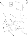
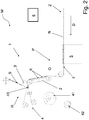
- the label-rejecting station comprises a deviator element 2, arranged along the advancing path P and movable between an inactive position I ( Figure 1 ) and an active position O ( Figures 2 and 3 ), wherein it contacts the support band N at its first surface F, deviating its advancing path P.
- the rejecting station 1 comprises a contrast element 3, arranged along the advancing path P, downstream of the deviator element 2.
- the contrast element 3 comprises: an abutting surface 30, designed to partially receive thereon the second surface S of the support band N (opposite to the first surface F) advancing of the support band N; and a detachment edge 31 (indicated in Figure 3 ), designed to detach a label E from the support band N (in particular, from the first surface F of the support band N) when the deviator element 2 moves into the relative active position O (see Figures 2 and 3 ).
- the label-rejecting station 1 proposed with the invention considerably reduces the loss of tension of the support band N in the case of rejection of a label E compared to known solutions, i.e., in the case of deviation of the advancing path P.
- the deviator element 2 and the contrast element 3 contrary to the known art, are made up of two distinct elements that cooperate to allow the detachment of a label E to be discarded when needed.
- the deviator element 2 and the contrast element 3 operate at two opposite surfaces F, S of the support band N.
- This aspect advantageously, translates into the fact that a minimum deviation of the support band N is required (by means of the deviator element 2) until detachment of a label E to be discarded (i.e., its lifting) from the supporting band N itself occurs, as will be made clearer below. From this it follows the fact that, even in the case of rejection of a label E, the tension of the support band N remains substantially unchanged compared to the case wherein it is not necessary to discard a label E, thus ensuring the correct application of the labels E to the relative articles.
- the contrast element 3 is arranged in a fixed manner along the advancing path P.
- the contrast element 3 is neither movable with respect to the support band N, nor with respect to the deviator element 2 (both when the latter is in the relative inactive position I, and when the latter is in the relative active position O).
- This aspect guarantees a particular structural and functional simplicity, as it is the only deviator element 2 that is movable, although the contrast element 3 also contributes to the detachment of a label E from the support band N.
- the abutting surface 30 of the contrast element 3 partially receives the support band N resting in a portion of the advancing path P downstream of the deviator element 2, in particular, both when the latter is in the relative inactive position I, and when the latter is in the relative active position O.
- the abutting surface 30 of the contrast element 3 has an arch-shaped development (i.e., it defines a curved profile). This aspect avoids the unwanted detachment of labels E when the deviator element 2 is in its inactive position I.
- the detachment edge 31 of the contrast element 3 comprises a corner 31 formed between two adjacent sides 32, 33 of the contrast element 3, with the two sides 32, 33 of the contrast element 3 that form an acute U angle between them.
- the detachment edge 31, preferably, consists of this corner 31 of the contrast element 3.
- one of the two sides 32, 33 of the contrast element 3 comprises the aforementioned abutting surface 30 (see Figure 3 ).
- the contrast element 3 has a hemispherical or semi-elliptical cross-section.
- the deviator element 2 has a prevailing longitudinal axis of development H and is movable by swinging between the inactive position I and the active position O around a swinging axis K passing through its axis of development (see Figure 3 ).
- the deviator element 2 is rod-shaped.
- the swinging axis K of the deviator element 2 is perpendicular to the longitudinal axis of development H of the deviator element 2. More specifically, the swinging axis K is preferably perpendicular to the lying plane (not indicated in the figures) of the deviator element 2.
- the longitudinal development axis H of the deviator element 2 is arranged partially parallel to the advancing path P (i.e., it is parallel to a section of this advancing path P).
- the deviator element 2 partially supports the support band N when it is arranged in the relative inactive position I and when it is arranged in the relative active position O.
- this aspect further reduces the deviation necessary to detach a label E from the support band N, i.e., the swinging angle of the deviator element 2 around its swinging axis K.
- the deviator element 2 carries at least one roller 20 at one of its ends, to facilitate the sliding of the support band N thereon. With reference to the attached figures, the deviator element 2 carries two rollers 20, one at each of its opposite ends.
- the swinging angle of the deviator element 2 (between the inactive position I and the active position O) is between 25° and 45°. This angle is particularly reduced, thus allowing a lower loss of tension of the support band N compared to the known art. Even more preferably, this angle is comprised between 30° and 40°. This range of values allows an even lower loss of tension than known solutions. With reference to the attached figures, the deviation angle is 33°. This value is an optimal compromise between the need to deviate the advancing path P of the support band N to obtain the correct detachment of a label E from the support band N itself, and the need to minimize the tension of the support band N following such a deviation.
- the rejecting station 1 preferably also comprises a collecting band 4 of the rejected labels E, which extends along a collection path R (indicated in a generic way in Figures 1 and 2 ) of the labels E, arranged adjacent to the advancing path P of the support band N at least at the contrast element 3.
- the collecting band 4 is designed to receive a label E detached from the support band N following the movement of the deviator element 2 into its active position O.
- the collecting band 4 is wrapped at least partially around a collection roller 41, which can be activated in rotation around its own axis to move the collecting band 4 when the deviator element 2 moves into the relative active position O.
- the collection roller 41 can be activated in rotation to move the collecting band 4 at the same advancing speed as the support band N when the deviator element 2 moves into the relative active position O, so as to allow the optimal passage of the label E from the support band N to the collecting band 4 (i.e. the detachment of the label E to be discarded from the support band N and its "automatic" adhesion to the collecting band 4).
- an unwinding roller 42 that rotates in a rotation direction opposite to that of the collecting roller 41 to unwind the collecting band 4 as it is wound onto the collecting roller 41 (see Figures 1 and 2 ). Between the unwinding roller 42 and the collecting roller 41 there are a series of return rollers 43 that determine the collecting path R.
- the return rollers 43 keep the collecting band 4 adjacent to the support band N, both when the deviator element is in the relative inactive position I, and when the deviator element 2 is in the relative active position O.
- This aspect guarantees an easy passage of a label E to be discarded from the support band N to the collecting band 4.
- the collecting band 4 is tangent to the support band N at least at the abutting surface 30 of the contrast element 3, near or at the detachment edge 31. This aspect guarantees even more the correct adhesion of a rejected label E to the collecting band 4.
- the rejecting station 1 also comprises a sensor 5 arranged along the advancing path P of the support band N upstream of the deviator element 2 (and of the contrast element 3), arranged to detect the possible non-conformity of a label E on the support band N, and to send a corresponding signal.
- the sensor 5 is preferably arranged to face the first surface F of the support band N.
- the rejecting station 1 further comprises a control unit 6 (schematically illustrated in Figures 1 and 2 ), arranged to receive the signal from the sensor 5, and consequently to control the deviator element 2 so that it moves to the relative active position O.
- a control unit 6 (schematically illustrated in Figures 1 and 2 ), arranged to receive the signal from the sensor 5, and consequently to control the deviator element 2 so that it moves to the relative active position O.
- An inconsistency of a label E may regard, for example, its printing: which could - in fact - be faded, not very visible, partially or completely missing.
- control unit 6 is also provided for commanding the collecting roller 41 to rotate in order to move the collecting band 4 when the signal has been received.
- the senor 5 is a sensor 5 of the optical type (camera, video camera, photocell or other).
- the labels E are fed - carried by the support band N - along the advancing path P at the feeding zone Z, first arriving at the sensor 5 for checking the conformity of the labels E. If the labels E are all compliant, (that is they do not have irregularities or printing errors), they pass through the rejecting station 1, with the deviator element 2 remaining in the relative inactive position I ( Figure 1 ) and receiving the first surface F of the support band N partially thereon.
- the support band N with the labels E is conveyed towards the application zone (not illustrated), where the labels E will be applied onto respective articles.
- the sensor 5 during the advancement of the support band N, detects a non-compliant label E, it sends a corresponding signal to the control unit 6.
- This activates the deviator element 2 so that it moves to the second position when the label E to be discarded is at the detachment edge 31 of the contrast element 3. Also in this situation, the deviator element 2 receives a portion of the support band N resting thereon.
- the control unit 6 also activates the collecting roller 41 to move the collecting band 4 at the same speed as the support band N, to receive and remove the label E detached from the support band N.
- the invention also relates to a labelling machine M (partially visible in Figures 1 and 2 ) comprising: a feeding zone Z of labels E, where the labels E are fed supported by the support band N, and a zone (not illustrated) for applying the labels E to corresponding articles.
- the labelling machine M also comprises a rejecting station 1 for labels E in accordance with any of the previous embodiments described, interposed between the feeding zone Z and the label-application zone.
- the labelling machine M is preferably a labelling machine M of the pharmaceutical sector.
Landscapes
- Labeling Devices (AREA)
- Input Circuits Of Receivers And Coupling Of Receivers And Audio Equipment (AREA)
- Pharmaceuticals Containing Other Organic And Inorganic Compounds (AREA)
Abstract
Description
- The present invention relates to a station for rejecting labels, which can be used in a labelling machine.
- Labelling machines, for example in the pharmaceutical sector, are used to apply - on various types of articles, for example, containers such as vials or bottles - relative self-adhesive labels that contain information printed on them (identification code/bar code of the article, contents and/or its expiration date, etc.).
- A labelling machine, in general, comprises, in succession: a station for feeding the labels, wherein the labels to be applied to the articles are fed, supported by a band, along an advancing path; a control station and a label-rejection station where, respectively, the compliance of the labels is checked and any non-compliant labels are discarded. Finally, a station for applying the labels is provided, arranged at the end of the advancing path, where the labels are applied to the respective articles.
- In the label-control station, as said, the conformity of the labels themselves, and - in particular - of their printing, is checked: it may happen, indeed, that the printed information is faded, partially or completely missing. To this end, the control station comprises a control system generally of the optical type.
- In the event that a label is compliant, it proceeds along the advancing path until it reaches the application station, where it is applied to a respective article. If, on the other hand, the control system detects the non-conformity of a label, the label must be discarded to prevent it from being applied incorrectly on an item.
- For this purpose, the label-rejecting station comprises a deviator and detachment element, which is arranged along the advancing path, and is activated to deviate the support band of the labels at the label to be rejected. The deviation angle of the band of the labels must be large enough to ensure the detachment of the label from the band itself, or rather, its lifting with respect to the band. Therefore, the deviator and detachment element usually acts along a direction perpendicular to the advancing path of the band, to divert its path.
- The rejecting station further comprises a roller for collecting the rejected labels, arranged to intercept a label that is lifted from the support band by the deviator and detachment element, thus attaching itself to the collection roller itself.
- However, the known solution described above has a drawback.
- In fact, the deviation of the path of the support band, useful for guaranteeing the detachment of the non-compliant label from it, involves a decrease in the tensioning of the support band itself, which is carried to travel a significantly longer path than the path taken in the event of compliant labels. This loss, even partial, of tension often results in a non-optimal and imprecise application of compliant labels to the respective articles, which may lead to the rejection of the articles themselves.
- The object of the present invention is to overcome the aforementioned drawback.
- This object is achieved by proposing a label-rejecting station in accordance with the attached claims.
- Advantageously, the label-rejecting station according to the present invention allows rejection of non-compliant labels, while still ensuring optimal application of the compliant labels to the respective articles. In other words, the presented solution guarantees the tensioning of the support band even in the case of rejection of one or more labels.
- Specific embodiments of the invention and further advantages will be made evident in the following description, with the aid of the attached drawings, in which:
-
Figure 1 schematically illustrates a label-rejecting station according to the invention, in a first operating configuration; -
Figure 2 schematically illustrates a label-rejecting station according to the invention, in a second operating configuration; -
Figure 3 is an enlarged view of a part ofFigure 2 . - With reference to the attached
Figures 1 and2 ,numeral 1 indicates a label-rejecting station according to the present invention. - As previously specified, the labels E are of the self-adhesive type and may be applied to any type of article, for example, containers in the pharmaceutical sector. The labels E may include some printing containing information of different types (identification code/barcode of the article, content and/or relative expiry date, logo/image, etc.).
- The labels E are carried by a support band N along an advancing path P (indicated generically in
Figures 1 and2 ). With reference to the attached figures, the labels E are shown schematically only along part of the support band N. - The advancing path P develops from a feeding zone Z wherein the labels E to be applied to the articles are fed, supported by the support band N, to a label-application zone (not illustrated) where the labels E are applied to the respective articles (also not illustrated). The
rejecting station 1 is arranged between the feeding zone Z and the label-application area. - The support band N moves along a feed direction D and comprises two surfaces opposite each other, first F and second S, with the labels E being applied to the first surface F of the support band N.
- The label-rejecting station according to the invention comprises a
deviator element 2, arranged along the advancing path P and movable between an inactive position I (Figure 1 ) and an active position O (Figures 2 and3 ), wherein it contacts the support band N at its first surface F, deviating its advancing path P. - In particular, the rejecting
station 1 comprises acontrast element 3, arranged along the advancing path P, downstream of thedeviator element 2. Thecontrast element 3, in turn, comprises: anabutting surface 30, designed to partially receive thereon the second surface S of the support band N (opposite to the first surface F) advancing of the support band N; and a detachment edge 31 (indicated inFigure 3 ), designed to detach a label E from the support band N (in particular, from the first surface F of the support band N) when thedeviator element 2 moves into the relative active position O (seeFigures 2 and3 ). - Advantageously, the label-rejecting
station 1 proposed with the invention considerably reduces the loss of tension of the support band N in the case of rejection of a label E compared to known solutions, i.e., in the case of deviation of the advancing path P. This is due to the fact that thedeviator element 2 and thecontrast element 3, contrary to the known art, are made up of two distinct elements that cooperate to allow the detachment of a label E to be discarded when needed. In particular, thedeviator element 2 and thecontrast element 3 operate at two opposite surfaces F, S of the support band N. This aspect, advantageously, translates into the fact that a minimum deviation of the support band N is required (by means of the deviator element 2) until detachment of a label E to be discarded (i.e., its lifting) from the supporting band N itself occurs, as will be made clearer below. From this it follows the fact that, even in the case of rejection of a label E, the tension of the support band N remains substantially unchanged compared to the case wherein it is not necessary to discard a label E, thus ensuring the correct application of the labels E to the relative articles. - According to the preferred embodiment, the
contrast element 3 is arranged in a fixed manner along the advancing path P. In other words, thecontrast element 3 is neither movable with respect to the support band N, nor with respect to the deviator element 2 (both when the latter is in the relative inactive position I, and when the latter is in the relative active position O). This aspect guarantees a particular structural and functional simplicity, as it is theonly deviator element 2 that is movable, although thecontrast element 3 also contributes to the detachment of a label E from the support band N. - As already said, the
abutting surface 30 of thecontrast element 3 partially receives the support band N resting in a portion of the advancing path P downstream of thedeviator element 2, in particular, both when the latter is in the relative inactive position I, and when the latter is in the relative active position O. - According to the preferred embodiment illustrated, the
abutting surface 30 of thecontrast element 3 has an arch-shaped development (i.e., it defines a curved profile). This aspect avoids the unwanted detachment of labels E when thedeviator element 2 is in its inactive position I. - According to the preferred embodiment illustrated, the
detachment edge 31 of thecontrast element 3 comprises acorner 31 formed between twoadjacent sides contrast element 3, with the twosides contrast element 3 that form an acute U angle between them. Thedetachment edge 31, preferably, consists of thiscorner 31 of thecontrast element 3. Preferably, one of the twosides contrast element 3 comprises the aforementioned abutting surface 30 (seeFigure 3 ). - According to a preferred embodiment, the
contrast element 3 has a hemispherical or semi-elliptical cross-section. - According to the preferred embodiment illustrated, the
deviator element 2 has a prevailing longitudinal axis of development H and is movable by swinging between the inactive position I and the active position O around a swinging axis K passing through its axis of development (seeFigure 3 ). Preferably, thedeviator element 2 is rod-shaped. - Preferably, the swinging axis K of the
deviator element 2 is perpendicular to the longitudinal axis of development H of thedeviator element 2. More specifically, the swinging axis K is preferably perpendicular to the lying plane (not indicated in the figures) of thedeviator element 2. - According to the preferred embodiment illustrated, the longitudinal development axis H of the
deviator element 2 is arranged partially parallel to the advancing path P (i.e., it is parallel to a section of this advancing path P). Even more preferably, again with reference to the attached figures, thedeviator element 2 partially supports the support band N when it is arranged in the relative inactive position I and when it is arranged in the relative active position O. Advantageously, this aspect further reduces the deviation necessary to detach a label E from the support band N, i.e., the swinging angle of thedeviator element 2 around its swinging axis K. - With reference to the attached figures, the
deviator element 2 carries at least oneroller 20 at one of its ends, to facilitate the sliding of the support band N thereon. With reference to the attached figures, thedeviator element 2 carries tworollers 20, one at each of its opposite ends. - Preferably, the swinging angle of the deviator element 2 (between the inactive position I and the active position O) is between 25° and 45°. This angle is particularly reduced, thus allowing a lower loss of tension of the support band N compared to the known art. Even more preferably, this angle is comprised between 30° and 40°. This range of values allows an even lower loss of tension than known solutions. With reference to the attached figures, the deviation angle is 33°. This value is an optimal compromise between the need to deviate the advancing path P of the support band N to obtain the correct detachment of a label E from the support band N itself, and the need to minimize the tension of the support band N following such a deviation.
- The rejecting
station 1 preferably also comprises a collectingband 4 of the rejected labels E, which extends along a collection path R (indicated in a generic way inFigures 1 and2 ) of the labels E, arranged adjacent to the advancing path P of the support band N at least at thecontrast element 3. Thecollecting band 4 is designed to receive a label E detached from the support band N following the movement of thedeviator element 2 into its active position O. - According to the preferred embodiment illustrated, the
collecting band 4 is wrapped at least partially around acollection roller 41, which can be activated in rotation around its own axis to move thecollecting band 4 when thedeviator element 2 moves into the relative active position O. Preferably, thecollection roller 41 can be activated in rotation to move thecollecting band 4 at the same advancing speed as the support band N when thedeviator element 2 moves into the relative active position O, so as to allow the optimal passage of the label E from the support band N to the collecting band 4 (i.e. the detachment of the label E to be discarded from the support band N and its "automatic" adhesion to the collecting band 4). On the opposite side of the collecting roller there is an unwindingroller 42 that rotates in a rotation direction opposite to that of the collectingroller 41 to unwind the collectingband 4 as it is wound onto the collecting roller 41 (seeFigures 1 and2 ). Between the unwindingroller 42 and the collectingroller 41 there are a series ofreturn rollers 43 that determine the collecting path R. - Preferably, the
return rollers 43 keep the collectingband 4 adjacent to the support band N, both when the deviator element is in the relative inactive position I, and when thedeviator element 2 is in the relative active position O. This aspect guarantees an easy passage of a label E to be discarded from the support band N to the collectingband 4. - According to the preferred embodiment, the collecting
band 4 is tangent to the support band N at least at the abuttingsurface 30 of thecontrast element 3, near or at thedetachment edge 31. This aspect guarantees even more the correct adhesion of a rejected label E to the collectingband 4. - According to the preferred embodiment, the rejecting
station 1 according to the invention also comprises asensor 5 arranged along the advancing path P of the support band N upstream of the deviator element 2 (and of the contrast element 3), arranged to detect the possible non-conformity of a label E on the support band N, and to send a corresponding signal. Thesensor 5 is preferably arranged to face the first surface F of the support band N. - The rejecting
station 1 further comprises a control unit 6 (schematically illustrated inFigures 1 and2 ), arranged to receive the signal from thesensor 5, and consequently to control thedeviator element 2 so that it moves to the relative active position O. - An inconsistency of a label E may regard, for example, its printing: which could - in fact - be faded, not very visible, partially or completely missing.
- According to the preferred embodiment, the
control unit 6 is also provided for commanding the collectingroller 41 to rotate in order to move the collectingband 4 when the signal has been received. - Preferably the
sensor 5 is asensor 5 of the optical type (camera, video camera, photocell or other). - The operation of the label-rejecting
station 1 according to the invention will now be briefly described, with reference to the attached figures. - The labels E are fed - carried by the support band N - along the advancing path P at the feeding zone Z, first arriving at the
sensor 5 for checking the conformity of the labels E. If the labels E are all compliant, (that is they do not have irregularities or printing errors), they pass through the rejectingstation 1, with thedeviator element 2 remaining in the relative inactive position I (Figure 1 ) and receiving the first surface F of the support band N partially thereon. The support band N, passing through the rejectingstation 1, then partially rests (with its second surface S) on the abuttingsurface 30 of thecontrast element 3, with the labels E remaining on the support band N itself (i.e., they do not detach). The support band N with the labels E is conveyed towards the application zone (not illustrated), where the labels E will be applied onto respective articles. The collectingband 4 and the collectingroller 41, in this situation, remain stationary. - If, on the other hand, the
sensor 5, during the advancement of the support band N, detects a non-compliant label E, it sends a corresponding signal to thecontrol unit 6. This activates thedeviator element 2 so that it moves to the second position when the label E to be discarded is at thedetachment edge 31 of thecontrast element 3. Also in this situation, thedeviator element 2 receives a portion of the support band N resting thereon. At the same time, thecontrol unit 6 also activates the collectingroller 41 to move the collectingband 4 at the same speed as the support band N, to receive and remove the label E detached from the support band N. - The invention also relates to a labelling machine M (partially visible in
Figures 1 and2 ) comprising: a feeding zone Z of labels E, where the labels E are fed supported by the support band N, and a zone (not illustrated) for applying the labels E to corresponding articles. The labelling machine M also comprises a rejectingstation 1 for labels E in accordance with any of the previous embodiments described, interposed between the feeding zone Z and the label-application zone. - The labelling machine M is preferably a labelling machine M of the pharmaceutical sector.
Claims (14)
- A label-rejecting station (1), the labels (E) being carried by a support band (N) along an advancing path (P), the rejecting station (1) comprises:- a deviator element (2), arranged along the advancing path (P), and movable between an inactive position (I) and an active position (O) wherein it contacts the support band (N) at a first surface (F) thereof, deviating the advancing path (P);characterized in that it comprises:- a contrast element (3), arranged along the advancing path (P) downstream of the deviator element (2), comprising in turn: an abutting surface (30) provided for receiving partially thereon a second surface (S) of the support band (N), opposite to the first surface (F), during its advancement; and a detachment edge (31) provided for detaching a label (E) from the support band (N) when the deviator element (2) moves into its active position (O).
- The rejecting station (1) according to the preceding claim, wherein the contrast element (3) is unmovable along the advancing path (P).
- The rejecting station (1) of any one of the preceding claims, wherein the abutting surface (30) of the contrast element (3) has an arch-shaped development.
- The rejecting station (1) of any one of the preceding claims, wherein the detachment edge (31) of the contrast element (3) comprises a corner (31) provided between two sides (32, 33) of the contrast element (3), the two sides (32, 33) of the contrast element defining an acute angle (U) between them.
- The rejecting station (1) of any one of the preceding claims, wherein the deviator element (2) has a prevailing longitudinal development axis (H) and is able to swing between the inactive position (I) and the active position (O) around a swinging axis (K) passing through its longitudinal development axis (H).
- The rejecting station (1) of the preceding claim, wherein the longitudinal development axis (H) of the deviator element (2) is at least partially parallel to the advancing path (P).
- The rejecting station (1) of the preceding claim, wherein the deviator element (2) partially receives the support band (N) when the deviator element (2) is in its inactive position (I) and when it is in its active position (O).
- The rejecting station (1) of any one of the preceding claims from 5 to 7, wherein the swinging angle of the deviator element (2) is between 25° and 45°, preferably between 30° and 40°, and more preferably is 33°.
- The rejecting station (1) of any one of the preceding claims, further comprising a collecting band (4) of the rejected labels (E) developing along a collecting path (R) of the labels (E), adjacent to the advancing path (P) of the support band (N) at least at the contrast element (3); the collecting band (4) being provided for receiving a label (E) detached from the support band (N) following the movement of the deviator element (2) into its active position (O).
- The rejecting station (1) of the preceding claim, wherein the collecting band (4) is at least partially wound around a collecting roller (41), which can be activated to rotate in order to move the collecting band (4) with a speed that is the same as the speed of the support band (N) when the deviator element (2) moves into its active position (O).
- The rejecting station (1) of any one of the preceding claims, comprising at least one sensor (5) arranged along the advancing path (P) upstream of the deviator element (2), provided for detecting an inconformity of a label (E) on the support band (N), and for sending a corresponding signal; and
a control unit (6), provided for receiving the signal from the sensor (5) and to command the deviator element (2) to move into its active position (O). - The rejecting station (1) of claims 10 and 11, wherein the control unit (6) is also provided for commanding the collecting roller (41) to rotate in order to move the collecting band (4) when the signal has been received.
- The rejecting station (1) of claims 11 or 12, wherein the sensor (5) is an optical sensor (5).
- A labelling machine (M) comprising:- a label-feeding zone (Z), the labels (E) being carried by a support band (N);- an application zone of the labels (E) to corresponding articles; and- a label-rejecting station (1) of any one of the preceding claims, arranged between label-feeding zone (Z) and label-attaching zone.
Applications Claiming Priority (1)
| Application Number | Priority Date | Filing Date | Title |
|---|---|---|---|
| IT102020000016363A IT202000016363A1 (en) | 2020-07-07 | 2020-07-07 | LABEL REJECTION STATION |
Publications (2)
| Publication Number | Publication Date |
|---|---|
| EP3936444A1 true EP3936444A1 (en) | 2022-01-12 |
| EP3936444B1 EP3936444B1 (en) | 2026-02-18 |
Family
ID=72801814
Family Applications (1)
| Application Number | Title | Priority Date | Filing Date |
|---|---|---|---|
| EP21182728.2A Active EP3936444B1 (en) | 2020-07-07 | 2021-06-30 | A label-rejecting station |
Country Status (6)
| Country | Link |
|---|---|
| US (1) | US11718437B2 (en) |
| EP (1) | EP3936444B1 (en) |
| JP (1) | JP7693994B2 (en) |
| KR (1) | KR20220005986A (en) |
| CN (1) | CN113895746B (en) |
| IT (1) | IT202000016363A1 (en) |
Citations (2)
| Publication number | Priority date | Publication date | Assignee | Title |
|---|---|---|---|---|
| EP1072520A1 (en) * | 1999-07-27 | 2001-01-31 | Neri S.p.A. | Checking and rejecting station for labels |
| WO2017055936A1 (en) * | 2015-09-28 | 2017-04-06 | Mevada Maheshkumar Jayantilal | Discarding defective label |
Family Cites Families (7)
| Publication number | Priority date | Publication date | Assignee | Title |
|---|---|---|---|---|
| US7416628B2 (en) * | 2004-06-14 | 2008-08-26 | Videojet Technologies, Inc. | Label applicator system with a peel inhibiting apparatus for RFID labels |
| SA110310799B1 (en) * | 2009-10-28 | 2014-07-14 | Sicpa Holding Sa | Label Ejection Device |
| JP5566143B2 (en) * | 2010-03-17 | 2014-08-06 | 株式会社岩田レーベル | Defective label collection device and label sticking device in a label conveying line for sticking |
| DE102011082450A1 (en) * | 2011-09-09 | 2013-03-14 | Krones Aktiengesellschaft | Device for the selective release of labels arranged on a carrier tape |
| JP6732498B2 (en) | 2016-03-31 | 2020-07-29 | トッパン・フォームズ株式会社 | Label manufacturing equipment |
| CN209635510U (en) * | 2019-02-27 | 2019-11-15 | 昆山杰拓电子科技有限公司 | It picks mark and mends marking device |
| KR102154773B1 (en) | 2019-09-30 | 2020-09-09 | 여환욱 | Large-area door apparatus and substrate processing apparatus |
-
2020
- 2020-07-07 IT IT102020000016363A patent/IT202000016363A1/en unknown
-
2021
- 2021-06-17 JP JP2021100798A patent/JP7693994B2/en active Active
- 2021-06-24 KR KR1020210081982A patent/KR20220005986A/en active Pending
- 2021-06-30 EP EP21182728.2A patent/EP3936444B1/en active Active
- 2021-07-06 US US17/367,789 patent/US11718437B2/en active Active
- 2021-07-07 CN CN202110766865.9A patent/CN113895746B/en active Active
Patent Citations (2)
| Publication number | Priority date | Publication date | Assignee | Title |
|---|---|---|---|---|
| EP1072520A1 (en) * | 1999-07-27 | 2001-01-31 | Neri S.p.A. | Checking and rejecting station for labels |
| WO2017055936A1 (en) * | 2015-09-28 | 2017-04-06 | Mevada Maheshkumar Jayantilal | Discarding defective label |
Also Published As
| Publication number | Publication date |
|---|---|
| CN113895746A (en) | 2022-01-07 |
| US20220009665A1 (en) | 2022-01-13 |
| JP2022014888A (en) | 2022-01-20 |
| JP7693994B2 (en) | 2025-06-18 |
| IT202000016363A1 (en) | 2022-01-07 |
| US11718437B2 (en) | 2023-08-08 |
| KR20220005986A (en) | 2022-01-14 |
| EP3936444B1 (en) | 2026-02-18 |
| CN113895746B (en) | 2025-07-01 |
Similar Documents
| Publication | Publication Date | Title |
|---|---|---|
| US5405482A (en) | Labeling machine | |
| US7935199B2 (en) | Printer-labeler and labeler | |
| EP1072520B1 (en) | Checking and rejecting station for labels | |
| US20100139866A1 (en) | Label pasting device | |
| CN119486941A (en) | Label feeding system with recovery mode and verification mode of sensor device | |
| WO2011114565A1 (en) | Label pasting device, and device for collecting defective labels in conveyor line for adhesive labels | |
| CN102548849B (en) | Markless registration system for labels in labelling machines | |
| EP4310038A1 (en) | Labelling machine for labelling containers adapted to contain a pourable product and method for splicing two webs of labelling material | |
| US20230347615A1 (en) | A Process for Automatically Correcting Defects on Self-Adhesive Labels on a Continuous Band | |
| AU2002250727B9 (en) | Methods and apparatus for producing and for applying labels | |
| CN107531435B (en) | Stock roll with functional marking, method for processing flat and/or tape material wound on stock roll, and apparatus for processing flat and/or tape material | |
| EP3936444B1 (en) | A label-rejecting station | |
| US12473115B2 (en) | Device for repairing objects fixed to a web, with a flexible feed mechanism of the web | |
| WO2001000492A1 (en) | Labelling apparatus | |
| US4798648A (en) | Article feeding devices for labellers | |
| CN102883959B (en) | Labelling machine and method thereof | |
| US11524810B2 (en) | Labelling machine and method for handling a web-like labelling material in an automated labelling process | |
| US20050274087A1 (en) | Device for applying a prepared handle to a pack | |
| CN108712985B (en) | Processing contoured wrap-around labels from a roll | |
| JP2002282939A (en) | Sheet material defect marking device and sheet material defect marking method | |
| US20260077896A1 (en) | Machine for forming filter bags for infusion products | |
| CN118613427A (en) | Device for removing defective labels from label support tape | |
| JP2002284415A (en) | Control method of web meandering correction device | |
| EP4619314A1 (en) | Label feeding system with visual control of the feeding with external reference | |
| WO2024121791A1 (en) | Rejected label diversion and collection system |
Legal Events
| Date | Code | Title | Description |
|---|---|---|---|
| PUAI | Public reference made under article 153(3) epc to a published international application that has entered the european phase |
Free format text: ORIGINAL CODE: 0009012 |
|
| STAA | Information on the status of an ep patent application or granted ep patent |
Free format text: STATUS: THE APPLICATION HAS BEEN PUBLISHED |
|
| AK | Designated contracting states |
Kind code of ref document: A1 Designated state(s): AL AT BE BG CH CY CZ DE DK EE ES FI FR GB GR HR HU IE IS IT LI LT LU LV MC MK MT NL NO PL PT RO RS SE SI SK SM TR |
|
| B565 | Issuance of search results under rule 164(2) epc |
Effective date: 20211208 |
|
| STAA | Information on the status of an ep patent application or granted ep patent |
Free format text: STATUS: REQUEST FOR EXAMINATION WAS MADE |
|
| 17P | Request for examination filed |
Effective date: 20220329 |
|
| RBV | Designated contracting states (corrected) |
Designated state(s): AL AT BE BG CH CY CZ DE DK EE ES FI FR GB GR HR HU IE IS IT LI LT LU LV MC MK MT NL NO PL PT RO RS SE SI SK SM TR |
|
| P01 | Opt-out of the competence of the unified patent court (upc) registered |
Effective date: 20230524 |
|
| GRAP | Despatch of communication of intention to grant a patent |
Free format text: ORIGINAL CODE: EPIDOSNIGR1 |
|
| STAA | Information on the status of an ep patent application or granted ep patent |
Free format text: STATUS: GRANT OF PATENT IS INTENDED |
|
| INTG | Intention to grant announced |
Effective date: 20251001 |
|
| GRAS | Grant fee paid |
Free format text: ORIGINAL CODE: EPIDOSNIGR3 |
|
| GRAA | (expected) grant |
Free format text: ORIGINAL CODE: 0009210 |
|
| STAA | Information on the status of an ep patent application or granted ep patent |
Free format text: STATUS: THE PATENT HAS BEEN GRANTED |
|
| AK | Designated contracting states |
Kind code of ref document: B1 Designated state(s): AL AT BE BG CH CY CZ DE DK EE ES FI FR GB GR HR HU IE IS IT LI LT LU LV MC MK MT NL NO PL PT RO RS SE SI SK SM TR |
|
| REG | Reference to a national code |
Ref country code: CH Ref legal event code: F10 Free format text: ST27 STATUS EVENT CODE: U-0-0-F10-F00 (AS PROVIDED BY THE NATIONAL OFFICE) Effective date: 20260218 Ref country code: GB Ref legal event code: FG4D |
|
| REG | Reference to a national code |
Ref country code: IE Ref legal event code: FG4D |
|
| REG | Reference to a national code |
Ref country code: DE Ref legal event code: R096 Ref document number: 602021048037 Country of ref document: DE |
|
| REG | Reference to a national code |
Ref country code: NL Ref legal event code: MP Effective date: 20260218 |
|
| PG25 | Lapsed in a contracting state [announced via postgrant information from national office to epo] |
Ref country code: RS Free format text: LAPSE BECAUSE OF FAILURE TO SUBMIT A TRANSLATION OF THE DESCRIPTION OR TO PAY THE FEE WITHIN THE PRESCRIBED TIME-LIMIT Effective date: 20260518 |
|
| PG25 | Lapsed in a contracting state [announced via postgrant information from national office to epo] |
Ref country code: ES Free format text: LAPSE BECAUSE OF FAILURE TO SUBMIT A TRANSLATION OF THE DESCRIPTION OR TO PAY THE FEE WITHIN THE PRESCRIBED TIME-LIMIT Effective date: 20260218 |
|
| PG25 | Lapsed in a contracting state [announced via postgrant information from national office to epo] |
Ref country code: PL Free format text: LAPSE BECAUSE OF FAILURE TO SUBMIT A TRANSLATION OF THE DESCRIPTION OR TO PAY THE FEE WITHIN THE PRESCRIBED TIME-LIMIT Effective date: 20260218 |
|
| PG25 | Lapsed in a contracting state [announced via postgrant information from national office to epo] |
Ref country code: GR Free format text: LAPSE BECAUSE OF FAILURE TO SUBMIT A TRANSLATION OF THE DESCRIPTION OR TO PAY THE FEE WITHIN THE PRESCRIBED TIME-LIMIT Effective date: 20260519 |
|
| REG | Reference to a national code |
Ref country code: LT Ref legal event code: MG9D |
|
| PG25 | Lapsed in a contracting state [announced via postgrant information from national office to epo] |
Ref country code: LT Free format text: LAPSE BECAUSE OF FAILURE TO SUBMIT A TRANSLATION OF THE DESCRIPTION OR TO PAY THE FEE WITHIN THE PRESCRIBED TIME-LIMIT Effective date: 20260218 |
|
| PGFP | Annual fee paid to national office [announced via postgrant information from national office to epo] |
Ref country code: DE Payment date: 20260629 Year of fee payment: 6 |
|
| PG25 | Lapsed in a contracting state [announced via postgrant information from national office to epo] |
Ref country code: NO Free format text: LAPSE BECAUSE OF FAILURE TO SUBMIT A TRANSLATION OF THE DESCRIPTION OR TO PAY THE FEE WITHIN THE PRESCRIBED TIME-LIMIT Effective date: 20260518 |
|
| PG25 | Lapsed in a contracting state [announced via postgrant information from national office to epo] |
Ref country code: FI Free format text: LAPSE BECAUSE OF FAILURE TO SUBMIT A TRANSLATION OF THE DESCRIPTION OR TO PAY THE FEE WITHIN THE PRESCRIBED TIME-LIMIT Effective date: 20260218 Ref country code: AT Free format text: LAPSE BECAUSE OF FAILURE TO SUBMIT A TRANSLATION OF THE DESCRIPTION OR TO PAY THE FEE WITHIN THE PRESCRIBED TIME-LIMIT Effective date: 20260218 Ref country code: SE Free format text: LAPSE BECAUSE OF FAILURE TO SUBMIT A TRANSLATION OF THE DESCRIPTION OR TO PAY THE FEE WITHIN THE PRESCRIBED TIME-LIMIT Effective date: 20260218 |
|
| REG | Reference to a national code |
Ref country code: AT Ref legal event code: MK05 Ref document number: 1887861 Country of ref document: AT Kind code of ref document: T Effective date: 20260218 |
|
| PG25 | Lapsed in a contracting state [announced via postgrant information from national office to epo] |
Ref country code: HR Free format text: LAPSE BECAUSE OF FAILURE TO SUBMIT A TRANSLATION OF THE DESCRIPTION OR TO PAY THE FEE WITHIN THE PRESCRIBED TIME-LIMIT Effective date: 20260218 |
|
| PG25 | Lapsed in a contracting state [announced via postgrant information from national office to epo] |
Ref country code: IS Free format text: LAPSE BECAUSE OF FAILURE TO SUBMIT A TRANSLATION OF THE DESCRIPTION OR TO PAY THE FEE WITHIN THE PRESCRIBED TIME-LIMIT Effective date: 20260618 Ref country code: PT Free format text: LAPSE BECAUSE OF FAILURE TO SUBMIT A TRANSLATION OF THE DESCRIPTION OR TO PAY THE FEE WITHIN THE PRESCRIBED TIME-LIMIT Effective date: 20260618 |
|
| PG25 | Lapsed in a contracting state [announced via postgrant information from national office to epo] |
Ref country code: NL Free format text: LAPSE BECAUSE OF FAILURE TO SUBMIT A TRANSLATION OF THE DESCRIPTION OR TO PAY THE FEE WITHIN THE PRESCRIBED TIME-LIMIT Effective date: 20260218 |
|
| PG25 | Lapsed in a contracting state [announced via postgrant information from national office to epo] |
Ref country code: LV Free format text: LAPSE BECAUSE OF FAILURE TO SUBMIT A TRANSLATION OF THE DESCRIPTION OR TO PAY THE FEE WITHIN THE PRESCRIBED TIME-LIMIT Effective date: 20260218 |
|
| PG25 | Lapsed in a contracting state [announced via postgrant information from national office to epo] |
Ref country code: BG Free format text: LAPSE BECAUSE OF FAILURE TO SUBMIT A TRANSLATION OF THE DESCRIPTION OR TO PAY THE FEE WITHIN THE PRESCRIBED TIME-LIMIT Effective date: 20260218 |