EP3936436B1 - Passenger seating - Google Patents
Passenger seating Download PDFInfo
- Publication number
- EP3936436B1 EP3936436B1 EP21183508.7A EP21183508A EP3936436B1 EP 3936436 B1 EP3936436 B1 EP 3936436B1 EP 21183508 A EP21183508 A EP 21183508A EP 3936436 B1 EP3936436 B1 EP 3936436B1
- Authority
- EP
- European Patent Office
- Prior art keywords
- door
- reel
- state
- base
- line
- Prior art date
- Legal status (The legal status is an assumption and is not a legal conclusion. Google has not performed a legal analysis and makes no representation as to the accuracy of the status listed.)
- Active
Links
Images


Classifications
-
- E—FIXED CONSTRUCTIONS
- E05—LOCKS; KEYS; WINDOW OR DOOR FITTINGS; SAFES
- E05F—DEVICES FOR MOVING WINGS INTO OPEN OR CLOSED POSITION; CHECKS FOR WINGS; WING FITTINGS NOT OTHERWISE PROVIDED FOR, CONCERNED WITH THE FUNCTIONING OF THE WING
- E05F15/00—Power-operated mechanisms for wings
- E05F15/60—Power-operated mechanisms for wings using electrical actuators
- E05F15/603—Power-operated mechanisms for wings using electrical actuators using rotary electromotors
- E05F15/632—Power-operated mechanisms for wings using electrical actuators using rotary electromotors for horizontally-sliding wings
- E05F15/643—Power-operated mechanisms for wings using electrical actuators using rotary electromotors for horizontally-sliding wings operated by flexible elongated pulling elements, e.g. belts, chains or cables
-
- B—PERFORMING OPERATIONS; TRANSPORTING
- B64—AIRCRAFT; AVIATION; COSMONAUTICS
- B64D—EQUIPMENT FOR FITTING IN OR TO AIRCRAFT; FLIGHT SUITS; PARACHUTES; ARRANGEMENT OR MOUNTING OF POWER PLANTS OR PROPULSION TRANSMISSIONS IN AIRCRAFT
- B64D11/00—Passenger or crew accommodation; Flight-deck installations not otherwise provided for
- B64D11/06—Arrangements of seats, or adaptations or details specially adapted for aircraft seats
-
- B—PERFORMING OPERATIONS; TRANSPORTING
- B64—AIRCRAFT; AVIATION; COSMONAUTICS
- B64C—AEROPLANES; HELICOPTERS
- B64C1/00—Fuselages; Constructional features common to fuselages, wings, stabilising surfaces or the like
- B64C1/14—Windows; Doors; Hatch covers or access panels; Surrounding frame structures; Canopies; Windscreens accessories therefor, e.g. pressure sensors, water deflectors, hinges, seals, handles, latches, windscreen wipers
- B64C1/1407—Doors; surrounding frames
- B64C1/1423—Passenger doors
- B64C1/1438—Passenger doors of the sliding type
-
- B—PERFORMING OPERATIONS; TRANSPORTING
- B64—AIRCRAFT; AVIATION; COSMONAUTICS
- B64C—AEROPLANES; HELICOPTERS
- B64C1/00—Fuselages; Constructional features common to fuselages, wings, stabilising surfaces or the like
- B64C1/14—Windows; Doors; Hatch covers or access panels; Surrounding frame structures; Canopies; Windscreens accessories therefor, e.g. pressure sensors, water deflectors, hinges, seals, handles, latches, windscreen wipers
- B64C1/1407—Doors; surrounding frames
- B64C1/1461—Structures of doors or surrounding frames
-
- B—PERFORMING OPERATIONS; TRANSPORTING
- B64—AIRCRAFT; AVIATION; COSMONAUTICS
- B64C—AEROPLANES; HELICOPTERS
- B64C1/00—Fuselages; Constructional features common to fuselages, wings, stabilising surfaces or the like
- B64C1/14—Windows; Doors; Hatch covers or access panels; Surrounding frame structures; Canopies; Windscreens accessories therefor, e.g. pressure sensors, water deflectors, hinges, seals, handles, latches, windscreen wipers
- B64C1/1407—Doors; surrounding frames
- B64C1/1469—Doors between cockpit and cabin
-
- B—PERFORMING OPERATIONS; TRANSPORTING
- B64—AIRCRAFT; AVIATION; COSMONAUTICS
- B64D—EQUIPMENT FOR FITTING IN OR TO AIRCRAFT; FLIGHT SUITS; PARACHUTES; ARRANGEMENT OR MOUNTING OF POWER PLANTS OR PROPULSION TRANSMISSIONS IN AIRCRAFT
- B64D11/00—Passenger or crew accommodation; Flight-deck installations not otherwise provided for
- B64D11/0023—Movable or removable cabin dividers, e.g. for class separation
-
- B—PERFORMING OPERATIONS; TRANSPORTING
- B64—AIRCRAFT; AVIATION; COSMONAUTICS
- B64D—EQUIPMENT FOR FITTING IN OR TO AIRCRAFT; FLIGHT SUITS; PARACHUTES; ARRANGEMENT OR MOUNTING OF POWER PLANTS OR PROPULSION TRANSMISSIONS IN AIRCRAFT
- B64D11/00—Passenger or crew accommodation; Flight-deck installations not otherwise provided for
- B64D11/06—Arrangements of seats, or adaptations or details specially adapted for aircraft seats
- B64D11/0602—Seat modules, i.e. seat systems including furniture separate from the seat itself
-
- B—PERFORMING OPERATIONS; TRANSPORTING
- B64—AIRCRAFT; AVIATION; COSMONAUTICS
- B64D—EQUIPMENT FOR FITTING IN OR TO AIRCRAFT; FLIGHT SUITS; PARACHUTES; ARRANGEMENT OR MOUNTING OF POWER PLANTS OR PROPULSION TRANSMISSIONS IN AIRCRAFT
- B64D11/00—Passenger or crew accommodation; Flight-deck installations not otherwise provided for
- B64D11/06—Arrangements of seats, or adaptations or details specially adapted for aircraft seats
- B64D11/0602—Seat modules, i.e. seat systems including furniture separate from the seat itself
- B64D11/0605—Seat modules, i.e. seat systems including furniture separate from the seat itself including tables or desks
-
- B—PERFORMING OPERATIONS; TRANSPORTING
- B64—AIRCRAFT; AVIATION; COSMONAUTICS
- B64D—EQUIPMENT FOR FITTING IN OR TO AIRCRAFT; FLIGHT SUITS; PARACHUTES; ARRANGEMENT OR MOUNTING OF POWER PLANTS OR PROPULSION TRANSMISSIONS IN AIRCRAFT
- B64D11/00—Passenger or crew accommodation; Flight-deck installations not otherwise provided for
- B64D11/06—Arrangements of seats, or adaptations or details specially adapted for aircraft seats
- B64D11/0606—Arrangements of seats, or adaptations or details specially adapted for aircraft seats with privacy shells, screens, separators or the like
-
- B—PERFORMING OPERATIONS; TRANSPORTING
- B64—AIRCRAFT; AVIATION; COSMONAUTICS
- B64D—EQUIPMENT FOR FITTING IN OR TO AIRCRAFT; FLIGHT SUITS; PARACHUTES; ARRANGEMENT OR MOUNTING OF POWER PLANTS OR PROPULSION TRANSMISSIONS IN AIRCRAFT
- B64D11/00—Passenger or crew accommodation; Flight-deck installations not otherwise provided for
- B64D11/06—Arrangements of seats, or adaptations or details specially adapted for aircraft seats
- B64D11/0638—Arrangements of seats, or adaptations or details specially adapted for aircraft seats with foldable tables, trays or cup holders
-
- E—FIXED CONSTRUCTIONS
- E05—LOCKS; KEYS; WINDOW OR DOOR FITTINGS; SAFES
- E05Y—INDEXING SCHEME ASSOCIATED WITH SUBCLASSES E05D AND E05F, RELATING TO CONSTRUCTION ELEMENTS, ELECTRIC CONTROL, POWER SUPPLY, POWER SIGNAL OR TRANSMISSION, USER INTERFACES, MOUNTING OR COUPLING, DETAILS, ACCESSORIES, AUXILIARY OPERATIONS NOT OTHERWISE PROVIDED FOR, APPLICATION THEREOF
- E05Y2201/00—Constructional elements; Accessories therefor
- E05Y2201/20—Brakes; Disengaging means; Holders; Stops; Valves; Accessories therefor
- E05Y2201/214—Disengaging means
- E05Y2201/216—Clutches
-
- E—FIXED CONSTRUCTIONS
- E05—LOCKS; KEYS; WINDOW OR DOOR FITTINGS; SAFES
- E05Y—INDEXING SCHEME ASSOCIATED WITH SUBCLASSES E05D AND E05F, RELATING TO CONSTRUCTION ELEMENTS, ELECTRIC CONTROL, POWER SUPPLY, POWER SIGNAL OR TRANSMISSION, USER INTERFACES, MOUNTING OR COUPLING, DETAILS, ACCESSORIES, AUXILIARY OPERATIONS NOT OTHERWISE PROVIDED FOR, APPLICATION THEREOF
- E05Y2201/00—Constructional elements; Accessories therefor
- E05Y2201/60—Suspension or transmission members; Accessories therefor
- E05Y2201/622—Suspension or transmission members elements
- E05Y2201/644—Flexible elongated pulling elements
- E05Y2201/654—Cables
-
- E—FIXED CONSTRUCTIONS
- E05—LOCKS; KEYS; WINDOW OR DOOR FITTINGS; SAFES
- E05Y—INDEXING SCHEME ASSOCIATED WITH SUBCLASSES E05D AND E05F, RELATING TO CONSTRUCTION ELEMENTS, ELECTRIC CONTROL, POWER SUPPLY, POWER SIGNAL OR TRANSMISSION, USER INTERFACES, MOUNTING OR COUPLING, DETAILS, ACCESSORIES, AUXILIARY OPERATIONS NOT OTHERWISE PROVIDED FOR, APPLICATION THEREOF
- E05Y2201/00—Constructional elements; Accessories therefor
- E05Y2201/60—Suspension or transmission members; Accessories therefor
- E05Y2201/622—Suspension or transmission members elements
- E05Y2201/658—Members cooperating with flexible elongated pulling elements
- E05Y2201/66—Deflectors; Guides
-
- E—FIXED CONSTRUCTIONS
- E05—LOCKS; KEYS; WINDOW OR DOOR FITTINGS; SAFES
- E05Y—INDEXING SCHEME ASSOCIATED WITH SUBCLASSES E05D AND E05F, RELATING TO CONSTRUCTION ELEMENTS, ELECTRIC CONTROL, POWER SUPPLY, POWER SIGNAL OR TRANSMISSION, USER INTERFACES, MOUNTING OR COUPLING, DETAILS, ACCESSORIES, AUXILIARY OPERATIONS NOT OTHERWISE PROVIDED FOR, APPLICATION THEREOF
- E05Y2201/00—Constructional elements; Accessories therefor
- E05Y2201/60—Suspension or transmission members; Accessories therefor
- E05Y2201/622—Suspension or transmission members elements
- E05Y2201/658—Members cooperating with flexible elongated pulling elements
- E05Y2201/668—Pulleys; Wheels
-
- E—FIXED CONSTRUCTIONS
- E05—LOCKS; KEYS; WINDOW OR DOOR FITTINGS; SAFES
- E05Y—INDEXING SCHEME ASSOCIATED WITH SUBCLASSES E05D AND E05F, RELATING TO CONSTRUCTION ELEMENTS, ELECTRIC CONTROL, POWER SUPPLY, POWER SIGNAL OR TRANSMISSION, USER INTERFACES, MOUNTING OR COUPLING, DETAILS, ACCESSORIES, AUXILIARY OPERATIONS NOT OTHERWISE PROVIDED FOR, APPLICATION THEREOF
- E05Y2201/00—Constructional elements; Accessories therefor
- E05Y2201/60—Suspension or transmission members; Accessories therefor
- E05Y2201/622—Suspension or transmission members elements
- E05Y2201/658—Members cooperating with flexible elongated pulling elements
- E05Y2201/672—Tensioners, tension sensors
-
- E—FIXED CONSTRUCTIONS
- E05—LOCKS; KEYS; WINDOW OR DOOR FITTINGS; SAFES
- E05Y—INDEXING SCHEME ASSOCIATED WITH SUBCLASSES E05D AND E05F, RELATING TO CONSTRUCTION ELEMENTS, ELECTRIC CONTROL, POWER SUPPLY, POWER SIGNAL OR TRANSMISSION, USER INTERFACES, MOUNTING OR COUPLING, DETAILS, ACCESSORIES, AUXILIARY OPERATIONS NOT OTHERWISE PROVIDED FOR, APPLICATION THEREOF
- E05Y2900/00—Application of doors, windows, wings or fittings thereof
- E05Y2900/50—Application of doors, windows, wings or fittings thereof for vehicles
- E05Y2900/502—Application of doors, windows, wings or fittings thereof for vehicles for aircraft or spacecraft
-
- E—FIXED CONSTRUCTIONS
- E05—LOCKS; KEYS; WINDOW OR DOOR FITTINGS; SAFES
- E05Y—INDEXING SCHEME ASSOCIATED WITH SUBCLASSES E05D AND E05F, RELATING TO CONSTRUCTION ELEMENTS, ELECTRIC CONTROL, POWER SUPPLY, POWER SIGNAL OR TRANSMISSION, USER INTERFACES, MOUNTING OR COUPLING, DETAILS, ACCESSORIES, AUXILIARY OPERATIONS NOT OTHERWISE PROVIDED FOR, APPLICATION THEREOF
- E05Y2900/00—Application of doors, windows, wings or fittings thereof
- E05Y2900/50—Application of doors, windows, wings or fittings thereof for vehicles
- E05Y2900/53—Type of wing
- E05Y2900/531—Doors
Definitions
- This invention relates to a passenger seating.
- the invention relates particularly to actuation systems for doors that are part of passenger seating, especially aircraft seating.
- UK patent application GB 2576505 discloses a sliding structure coupled to spring-loaded reels by flexible strips.
- the slide assembly comprises a base having a slot, and a sliding structure insertable into the slot and slidable along the slot.
- a strip of flexible material is fixed to a reel and to the sliding structure, wherein rotation of the reel in a first direction causes the strip to wind around the reel, and rotation of said reel in a second direction causes the strip to unwind from the reel.
- the strip is axially aligned with the slot mouth so that it covers, when unwound, a portion of the slot mouth.
- the strip prevents dirt from entering the slot as well as obscuring the inside of the slot from view.
- a second strip and reel may be employed on the distal side of the sliding structure, and the reels may be spring loaded to provide a balanced force.
- the sliding structure 24 may be a privacy screen on an aeroplane seat.
- European patent application EP 3069996 discloses an armrest assembly for aircraft seating in which a lockable actuator moves an upper structure with respect to a base structure.
- the armrest assembly comprises a base structure and an upper structure that has an upper surface providing an armrest.
- the upper structure is movable with respect to the base structure between an upper position and a lower position under the control of a lockable actuator that is operable to lock the upper structure with respect to the base structure in any one of a plurality of adoptable positions.
- a second locking device is operable to lock the upper structure with respect to the base structure in at least one of the adoptable positions, the locking device including locking elements that interengage mechanically when the second locking device locks the upper structure with respect to said base structure.
- European patent application EP 2248958 discloses a window in which multiple window sashes are slidable and retractable one above the other in a stacking box by a motor-operated reduction drive.
- German patent application DE 102011 008776 discloses a belt-lock feeder having a drive unit coupled with an adjusting mechanism, and a belt-lock movable from an initial position into feeding-position by a pre-stressed spring element, which is securely arranged within a guide.
- the invention provides a passenger seating as claimed in claim 1
- said motor is fixed with respect to one of the base or the door and coupled to the other of the base or the door for moving said door from said second state to said first state.
- the motor is a rotary motor having a rotary output, the output being coupled to the other of the base or the door.
- the rotary output shaft may be coupled to a reel, the reel being coupled to the other of the base or the door.
- the reel is typically fixed with respect to said one of the base or the door and carries a reel line that is coupled to the other of the base or the door, preferably via a pulley that is fixed with respect to said one of the base or the door.
- said drive means is operable to rotate said reel in a first rotational direction when said second actuating means actuates said door from said second state to said first state, wherein, preferably, rotation of said reel in said first rotational direction winds in said reel line.
- said drive means is operable to rotate said reel in a second rotational direction opposite to said first rotational direction, wherein, preferably, rotation of said reel in said second rotational direction winds out said reel line.
- the passenger seating is configured such that, when said first actuating means actuates said door from said first state to said second state, said second actuating means rotates said reel in said second rotational direction.
- the system may be configured such that, when said first actuating means actuates said door from said first state to said second state, said second actuating means rotates said reel in said second rotational direction at a speed that maintains tension in said reel line.
- the system includes at least one tensioning device arranged to maintain tension in the reel line, said at least one tensioning device preferably being coupled between said door and the reel line, and wherein said at least one tensioning device preferably comprises an elasticized tensioning line.
- Said at least one tensioning device is preferably arranged to take up slack in said reel line caused by movement of said door from said second state to said first state when said powered drive means is not rotating said reel.
- said system is configured to operate said powered drive means to rotate said reel to wind in said reel line by an amount corresponding to an amount of slack in said reel line caused by the movement of said door from said second state to said first state when said powered drive means is not rotating said reel.
- said powered drive means of said second actuating means is electrically powered.
- Said powered drive means preferably comprises an electric motor, preferably an electric rotary motor.
- said powered drive means is coupled to one or other of the base or the door by at least one clutch, preferably comprising an autodisconnect clutch, configured to allow manual movement of said door from said second state to said first state.
- said powered drive means of said second actuating means is coupled to one or other of the base or door by at least one clutch, preferably comprising an autodisconnect clutch, configured to allow movement of said door from said first state to said second state.
- at least one clutch preferably comprising an autodisconnect clutch, configured to allow movement of said door from said first state to said second state.
- Said rotary output shaft may be coupled to the other of the base or door, preferably to said reel, by said at least one clutch.
- Said first actuating means comprises resilient biasing means arranged to urge said door from said first state to said second state.
- the resilient biasing means may be coupled between the base and the door.
- the resilient biasing means typically comprises at least one spring, for example at least one mechanical spring and/or at least one gas spring.
- said at least one spring comprises a constant force spring.
- said at least one spring comprises a spiral spring.
- said first actuating means comprises a linear actuator, preferably a gas spring linear actuator.
- said second actuating means comprises a linear actuator, preferably ar electrically powered linear actuator, coupled between said base and said door.
- a linkage may be coupled between the base and the door, said linear actuator being coupled between the base and the linkage to move the door by acting on the linkage.
- Said first actuating means may be coupled between the base and the linkage.
- the linkage may be pivotably coupled to the base and to the door.
- Said first actuating means comprises resilient biasing means arranged to urge said door from said first state to said second state, said resilient biasing means preferably being coupled between the base and the door, wherein said resilient biasing means preferably comprises at least one spring, for example at least one mechanical spring and/or at least one gas spring, optionally a linear actuator, preferably a gas spring linear actuator.
- said first state corresponds to an extended or closed position of the door
- said second state corresponds to a retracted or open position of the door
- said first state corresponds to a retracted or open position of the door
- said door is movable linearly between said first and second states.
- the door in the open position, exposes a doorway providing passenger access to and from said at least one seat and, in the closed position, the door closes the doorway.
- the seating installation may comprise a plurality of rows, each row comprising at least one seat, and wherein said doorway is defined between the respective seat surround structure of adjacent rows, or between the seat surround structure of one row and a bulkhead.
- Preferred embodiments allow doors to be opened and closed using actuation means, including powered actuation means, while still being operable manually, e.g. in the event of an emergency.
- actuation means including powered actuation means
- a door can be open or closed automatically thereby giving a premium feel without giving rise to safety concerns.
- the seating 10 comprises at least one seat 12, usually a plurality of seats 12 arranged in an array of one or more rows R1, R2, each row having one or more seats 12.
- two rows R1, R2 each with a single respective seat 12 are shown by way of example only.
- a bulkhead (not shown) may be located in front of and/or behind the seating 10.
- an aisle is located alongside the seating 10 on one or both sides, typically running substantially perpendicular with the rows R1, R2.
- The, or each, aisle may separate the seating 10 from additional seating (not shown but which may be the same as the seating 10), bulkhead or cabin wall (not shown).
- Each seat 12 is typically located within a shell structure 14 that partially surrounds the seat 12.
- the shell structure 14 typically includes a back portion 16 behind the seat 12 and at least one side portion 18.
- the side portion 18 may include a console 20, which may be configured to serve as an armrest and/or may include a deployable table and/or other facilities.
- the shell structure 14 may be shared by more than one seat 12 of the same row R1, R2, for example being configured to provide the back portion 16 and side portion(s) for each seat 12.
- each row R1, R2 has a respective shell structure 14 configured to provide a respective back portion 16, a respective near side 18A including a side console 20, and a respective far side 18B for the seat 12 in the respective row R1, R2.
- a screen and/or a console separating adjacent seats in a row may be provided, conveniently as part of a common shell for the row.
- the seats 12 are typically of a type that can recline to form a bed.
- the shell structure 14 provides a seated passenger (not shown) with some privacy from other passengers seated in the same row and in adjacent rows. However, the shell structure 14 must allow space for the passengers to access the seat 12 from the aisle and vice versa. Accordingly, the side portion 18A that is, in use, adjacent an aisle is configured to provide a gap 24 for ingress to and egress from the end seat 12 in the respective row. In typical embodiments, this means that the side portion 18A does not extend fully and permanently to the shell structure 14 of the row in front, or to a bulkhead in front, as applicable. This is in contrast to the far side portion 18B which may extend fully and permanently to the to the shell structure 14 of the row in front, or to a bulkhead in front, as applicable.
- the side portion 18A comprises a door assembly 30.
- the door assembly 30 comprises a base portion 32 and a door 34 that is movable with respect to the base portion 32 between an open state and a closed state, the movement typically being linear.
- the base portion 32 extends along the aisle-side of the seat 12 typically from the back 16 of the shell 14, and is typically panel-like in form.
- the base portion 32 which is typically substantially rectangular in shape, provides a wall on one side (the aisle-side) of the seat 12, typically as part of the shell structure 14.
- the door 34 is movable with respect to the base 32 between an open state in which the ingress/egress gap 24 is provided, and a closed state in which the gap 24 is closed. It will be understood that the word “closed” in this context does not necessarily mean that the gap 24 is eradicated completely and is therefore intended to embrace “fully closed” and “substantially closed”.
- the door 34 is a sliding door, i.e. is slidable with respect to the base 32 between the open and closed states.
- the door 34 may be coupled to the base 32 by one or more slide mechanism, for example comprising slide rails and/or rollers, which may be provided at the top and/or bottom of the door 34.
- the base 32 comprises a compartment 42 for housing the door 34 when open, the compartment having a mouth 44 through which the door 34 slides into and out of the compartment.
- the compartment 42 is preferably dimensioned to house substantially the entire door 34 when open. Accordingly, when the door 34 is open, the gap 24 is defined between the leading end of the base 32 and the forward shell structure 14/bulkhead.
- the arrangement may be such that part of the door projects from the base 32 when open in which case the gap 24 is defined between the leading end of the door 34 and the forward shell structure 14/bulkhead.
- the arrangement may be such that the door 34 slides alongside the base portion rather than into a compartment in the base; in such cases the base portion may comprise a panel or any other base structure(s)
- the door assembly 30 provides some privacy along the aisle-side of the seat 12 whether or not the door 34 is open since the base 32 extends along side the seat 12, and is typically panel-like in form. However, greater privacy is provided when the door 34 is closed. It is preferred that, when the door 34 is open, the door assembly 30 (i.e. the leading edge of the base 32 or the leading edge of the open door 34 as applicable) extends no further forward than the forward end of the seat pan 46 of the seat 12 to ensure that an adequate gap 24 is provided. It will be apparent that that the height of the door assembly 30 affects the privacy afforded to the passenger. It is preferred that the height of the base 32 and the door 34 is approximately level with the head rest 48 of the seat 12. Preferably, the base 32 and the door 34 are each solid and opaque to maximize privacy.
- the door 34 is typically substantially rectangular in shape.
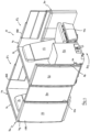
- FIG. 1 the door 34 of row R1 at the front of the seating 10 is shown in the open state, while the door 34 of row R2 at the back is shown in the closed state.
- a respective door assembly is provided for the seat at the or each end of each row, as required.
- a respective door assembly may be provided on each side of the seat, or only on one side, as required.
- the door assembly need not be at the side of a seat or a row of seats, but may alternatively be in front of or otherwise adjacent or associated with a seat or row of seats.
- the door assembly 30 includes actuation means 50 for moving the door 34 from the open state to the closed state.
- the actuating means 50 comprises resilient biasing means arranged to urge the door 34 from the open state to the closed state.
- the resilient biasing means is coupled between the base 32 and the door 34.
- the resilient biasing means may comprise at least one spring, for example at least one mechanical spring and/or at least one gas spring.
- the or each spring is a constant force spring.
- the resilient biasing means comprises a spiral spring 52.
- the spring 52 comprises a strip of resilient material (e.g. steel) that adopts a wound state (not shown) when relaxed and may be unwound against the spring-bias.
- One end 53 of the spring 52 is fixed or otherwise coupled to the base 32 while the other end is coupled to the door 34, typically via a reel 55.
- the arrangement is such that the spring 52 is unwound (as illustrated in Figure 2 ) when the door 34 is open, and so urges the door 34 to close under its spring bias.
- the free end 53 of spring 52 is fixed with respect to the base 32 while the other end, including the reel 55, is coupled to the door 34, although in alternative embodiments the opposite arrangement may be adopted.
- the door 34 may be returned to the open state by a user manually pushing the door 34 against the bias of the spring 52.
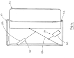
- the actuating means 150 may comprise one or more linear actuator 152, for example a gas spring linear actuator, a mechanical spring actuator, coupled between the door 34 and the base 32.
- the actuator 152 may be biased to adopt its extended state, e.g. by gas, mechanical or other resilient biasing means.
- the actuator 152 may be coupled to a linkage 156; extension of the actuator 152 causes the linkage 156 to push the door 34 closed.
- the illustrated linkage 156 is pivotably connected to the door 34 and may also be pivotably connected to the base 32, although it may alternatively abut against the base 32.
- the door 34 may be returned to the open state by a user manually pushing the door 34 against the bias of the actuator 152.
- the actuating means 50, 150 is configured to allow movement of the door 34 from the closed state to the open state.
- the or each spring 52 and/or actuator 152 may be of a type that allows operation in at least one direction (e.g. retraction and/or extension) by the application of mechanical force by a human user.
- the or each actuator 52, 152 may be a spring or a spring-biased actuator (e.g. comprising a gas spring or mechanical spring) or a single-acting ram, wherein extension (or retraction) of the actuator is effected by the spring bias, and retraction (or extension) of the actuator may be performed manually against the spring-bias.
- the actuation means 50 is part of an actuation system.
- the actuation system includes second actuating means for actuating the door 34 from the closed state to the open state.
- Figure 2 illustrates, generally indicated as 60, a preferred embodiment of the second actuating means, shown in exploded view together with the door 34.
- the second actuating means 60 is power-operated, comprising powered drive means 62, preferably electrically powered drive means.
- the drive means 62 typically comprises a motor, preferably a rotary motor, optionally a reversible rotary motor.
- the motor is preferably an electric motor (AC or DC as is convenient).
- the drive means 62 is provided on the base 32 or is otherwise located such that it has a fixed position with respect to the base 32, and is coupled to the door 34 in order to move the door 34 from its closed state to its open state. Conveniently, the drive means 62 is located within the compartment 42.
- the motor is a rotary motor, it has a rotary output that is coupled to the door 34.
- the coupling translates rotation of the output shaft into linear movement of the door 34.
- the coupling comprises a reel 64, wherein the rotary output shaft is coupled to the reel 64, the reel 64 being coupled to the door 34.
- the reel 64 is in a fixed location with respect to the base 32 and carries a reel line (shown schematically as 65), e.g. comprising wire of metal or other suitable material, that is fixed or otherwise coupled to the door 34, preferably via a pulley 66 or other suitable line guide(s).
- the reel 64 may be positioned beneath, or lower than, the door 34.
- the pulley 66 is in a fixed location with respect to the base 32, conveniently being located at the rear of the door 34 when the door 34 is open and/or level with the line 65 as it comes off the reel 64.
- the pulley 66 and reel 64 are located relative to each other to allow the door 34 to be fully retracted.
- the reel 64 is located forwardly of the pulley 66 (assuming that the door 34 moves forwardly to close).
- the arrangement is such that when the door 34 is closed, the reel line 65 is unwound from the reel 64 via the pulley 66.
- the drive means 62 is operated to rotate the reel 64 to wind in the reel line 65 via the pulley 66 thereby opening the door 34.
- the drive means 62 and reel 64 may have a fixed location with respect to the door 34 and the end of the reel line 65 may be fixed or otherwise coupled to the base 32.
- the reel line may be fixed directly to the door 34 and the pulley 66 may be omitted.
- the second actuating means 60 is coupled between the door 34 and base 32 and is operable to open the door.
- one or more tensioning device (not shown), for example comprising a spring, is provided for maintaining tension in the line 65.
- the tensioning device(s) may be coupled to or incorporated into the reel 64 and/or the pulley 66.
- the powered drive means 62 is coupled to the door 34 by a clutch 68 that is configured to allow manual movement of the door 34 from the closed state to the open state, and/or to allow manual movement of the door 43 from the open state to the closed state and/or to allow movement of the door 43 from the open state to the closed state under the action of the actuating means 50, 150.
- the clutch 68 is configured to mechanically couple the drive means 62 to the driven object, i.e.
- a type of clutch 68 known as an autodisconnect clutch is suitable for use as clutch 68.
- the rotary output of the motor 62 is coupled to the door 34, preferably via the reel 64, by the clutch 68.
- the clutch 68 may couple the motor to the base 32.
- the clutch 68 is shown as part of an assembly that further includes a collar 69 for the clutch 68 and an adaptor 71 for coupling the drive means 62 to the assembly.
- the assembly and reel 64 are shown in exploded view in Figure 2 , and are assembled together in use as would be apparent to a skilled person. It will be understood that the invention is not limited to the particular configuration of clutch assembly shown in Figure 2 and other configuration may be used as desired.
- the operation of the clutch 38 is such that, when the motor 62 is operated (in particular to open the door), the clutch 68 transmits the rotational output of the motor 62 to the reel 64, causing the reel 64 to rotate to wind the reel line 65.
- the clutch 68 allows the reel 64 to freewheel, i.e. rotate freely, with respect to the drive means 62.
- a user-operable latch (not shown) is provided for holding the door 34 in its open state.
- the latch may take any conventional form, typically being mechanical or electromechanical.
- a first user control device (not shown) is provided, preferably within reach of a seated passenger, and is linked to the latch to allow the user to operate the latch, in particular to release the door 34.
- the user control device may take any conventional form, e.g. being mechanical, electromechanical or electrical, and may be linked to the latch by any suitable mechanical, electromechanical or electrical link (which may be wired or wireless).
- the preferred arrangement is that the actuating means 50, more particularly the spring 52 and actuator 152 in the illustrated embodiments, is biased to urge the door 34 from the open state to the closed state. Therefore, starting with the door 34 in the open state, when the user operates the latch to release the door 34, the actuating means 50 moves the door 34 to the closed state.
- a second user control device (not shown) is provided, preferably within reach of a seated passenger, and is linked to the actuation means 60 for operating the powered drive means 62.
- the second user control device may take any conventional form, typically comprising a switch or button, and is linked to the drive means 62 by any suitable control link, typically an electrical wired or wireless connection.
- the reel line 65 is in an extended state when the door 34 is closed (having been unwound from the reel 64 as the door 34 moves towards the open state) and operation of the drive means 62 rotates the reel 64 to retract the reel line 65 by winding it around the reel 64 thereby pulling the door 34 towards and ultimately into the open state.
- the first and second user control devices may be provided in the same passenger control unit, or in a different passenger control unit, as is convenient.
- the actuation means 50 is configured to allow movement of the door 34 from the closed state to the open state against its resilient bias.
- the spring 52 can be unwound or extended against its resilient bias.
- the actuation means 50 does not prevent movement of the door 34 from the closed state to the open state whether such movement is effected by the drive means 62 or manually by a user.
- the power of the drive means 62 is such that it may overcome the resilient bias of the actuation means 50.
- the powered actuation means 60 is configured to allow the door 34 to move from the open state to the closed state so that it does not prevent operation of the actuation means 50. In the embodiment of Figure 2 , this is achieved by the clutch 68.
- the clutch 68 allows the reel 64 to rotate in a direction opposite to the direction in which it rotates when the door 34 is being opened. In the embodiment of Figure 2 , movement of the door 34 toward the closed state pulls the reel line 65 thereby causing as the reel 54 to rotate as the reel line unwinds.
- the powered actuation means 60 is configured so that it does not prevent movement of the door 34 from the closed state to the open state when such movement is effected manually by a user. In the embodiment of Figure 2 , this is facilitated by the tensioning device acting to wind in the line 65 as the door is opened, and/or may be facilitated by the clutch 68.
- the clutch 68 may be an autodisconnect clutch.
- the clutch may be configured so that up to an operational limit (which may be above what is experienced during normal operation of the drive means 62 when opening the door 34), the clutch 68 engages to transmit power from the drive means 62 to the door 34 (via the reel 64 in the embodiment of Figure 2 ), but that above the limit the clutch 68 disengages to allow the door 34 to move in the direction towards the open state or closed state as applicable.
- the operational limit relates to any suitable operational parameter, typically torque, force or speed, depending on the type of the clutch.
- the clutch 68 disengages so that the rotation of the reel 64 as the door 34 is manually opened is not imparted to the drive means 62.
- any arrangement of one or more conventional clutches e.g. freewheel clutch(es), torque limiting clutch(es) and/or overrunning clutch(es) may be provided to give the functionality described herein.
- the door 34 can be opened and closed by the actuation means 50, 60, but can also be opened manually in the event of emergency or should the powered drive means 62 fail.
- Figure 3 illustrates a preferred embodiment of the actuation system, which is similar to the actuation system of Figure 2 and in which like numerals are used to denote like parts and the same or similar description applies unless otherwise indicated as would be apparent to a skilled person.
- Figure 3 shows the actuation system coupled to the door 34, which is only partly shown.
- the actuation system of Figure 3 has a first actuating means (not shown) which may be the same or similar to the actuating means 50 of Figure 2 or the actuating means 150 of Figure 4 .
- the second actuating means 260 is power-operated, comprising powered drive means 62, preferably electrically powered drive means.
- the drive means 62 typically comprises a motor, preferably a rotary motor, in particular a reversible rotary motor.
- the drive means 62 is provided on the base 32 or is otherwise located such that it has a fixed position with respect to the base 32, and is coupled to the door 34 in order to move the door 34 from its closed state to its open state, and preferably also from the open state to the closed state.
- the drive means 62 is located within the compartment 42.
- the motor is a rotary motor
- it has a rotary output that is coupled to the door 34.
- the coupling translates rotation of the output shaft into linear movement of the door 34.
- the coupling comprises reel 64, wherein the rotary output shaft is coupled to the reel 64, the reel 64 being coupled to the door 34.
- the reel 64 is in a fixed location with respect to the base 32 and carries reel line 265, e.g. comprising wire of metal or other suitable material, which is fixed or otherwise coupled to the door 34, preferably via at least one pulley 266A - 266C.
- the reel 64 may be positioned beneath, or lower than, the door 34.
- Each pulley 266A - 266C is in a fixed location with respect to the base 32.
- the line 265 is connected to the door 34 at a located between the bottom and top of the door 34, preferably at or adjacent the forward end of the door 34, or between the forward and rearward ends of the door 34.
- the pulleys 266A-266C are arranged such that the line 265 is guided between the reel 64 and the connection location on the door 34.
- Pulley 266A is preferably located at the rear of the door 34 when the door 34 is open, preferably at or below the level of the bottom of the door 34 and/or level with the line 265 as it comes off the reel 64.
- Pulley 266B is preferably located at the rear of the door 34 when the door 34 is open, preferably above the level of the bottom of the door 34, more preferably level with the location at which the line 265 is connected to the door 34.
- Pulley 266C is optional but when present is located between pulleys 266A and 266B.
- any one or more of the pulleys 266A-266C may comprise a line guide or line support and does not need to be a pulley.
- the pulleys 266A-266C and reel 64 are located relative to each other to allow the door 34 to be fully retracted and extended.
- the reel 64 is located forwardly of the at least the first pulley 266A (assuming that the door 34 moves forwardly to close). The arrangement is such that when the door 34 is closed, the reel line 265 is unwound from the reel 64 via the pulleys 266A-266C.
- the drive means 62 is operated to rotate the reel 64 to wind in the reel line 265 via the pulleys 266A-266C thereby opening the door 34.
- the location at which the reel line 265 is connected to the door 34 is preferred as it facilitates a smoother opening movement.
- the tensioning device 267 is provided for maintaining tension in the line 265.
- the tensioning device 267 is coupled between the door 34 and the reel line 265.
- the tensioning device 267 may comprise an elasticized tensioning line 267A.
- the tensioning line 267A may comprise one or more spring, or one or more lengths of wire connected to one or more springs, or a line made from elastic material.
- the tensioning line 267A may be coupled to the door 34 by any convenient fixing device.
- the tensioning line 267A may be coupled to the reel line 265 by line guide 267B that allows the line 265 to run through it.
- the tensioning line 267A is coupled to the reel line 265 at a location between two line guides, e.g. between pulleys 266B and 266C in the illustrated example.
- the tensioning line 267A in held under tension at least when the door 34 is out of its open state.
- the actuating means 260 is operable not only to open the door 34 as described above, but also when the door 34 is being actuated to its closed state.
- the drive means 62 is operated to rotate the reel 64 in one rotational direction when opening the door 34 (to wind in the reel line 265) and in the opposite rotational direction when the door 34 is being closed (to wind out the reel line 265).
- the clutch 68 may be omitted.
- the first actuating means 50, 150 still provides the force for moving the door 34 from the open state to the closed state.
- the drive means 62 is operated to wind out the reel line 265 at a speed that maintains tension in the reel line 265.
- the drive means 62 is operated to wind out the reel line 265 at a speed that matches or is slower than the speed at which the action of the first actuating means 50, 150 pulls the reel line 265 when moving the door 34.
- the action of the second actuating means 260 when the door 34 is moved to the closed state helps to control the movement of the door 34, for example by applying a braking force.
- the user control device that is operable to operate the first actuating means 50, 150 to close the door 34 also operates the second actuating means 260 as described above.
- any slack in the reel line 265 is taken up by the tensioning device 267, advantageously keeping the reel line 265 under tension.
- This facilitates keeping the reel line 265 in a state (e.g. kept in contact with the relevant pulleys/guides) that allows the second actuating means 260 to resume its normal operation.
- the drive means 62 may be operated to wind in the reel line 265 by an amount corresponding to the amount of slack caused by the manual opening.
- This operation may be performed automatically by a controller (not shown) which may take any suitable conventional form (e.g. a microprocessor or microcontroller based controller).
- one or more position sensors are provided to determine the position of the door 34, and the controller is configured to wind in the reel line 265 depending on the position of the door 34 indicated by the sensor(s).
- the second actuating means 160 comprises powered drive means in the form of a linear actuator 162, preferably an electrically powered linear actuator.
- a linear actuator 162 When power is supplied to the actuator 162, i.e. when it is turned on, it extends (or retracts as applicable).
- power When power is not supplied to the actuator 162, i.e. when it is turned off, it may freely be caused to retract (or extend as applicable) by application of an external force.
- the actuator 162 is coupled between the base 32 and the door 34, via linkage 156 in this example.
- the linkage 156 which may comprise one or more bar or other suitable structure(s), is coupled between the base 32 and the door 34.
- the linear actuator 162 is coupled between the base 32 and the linkage 156 and is arranged to move the door 34 from the closed state to the open state by acting on the linkage 156.
- the non-powered, resiliently biased actuator 152 is coupled between the base 32 and the linkage 156 and is arranged to move the door from the open state to the closed state. As such, the actuators 152, 162 may be arranged to move the linkage 156 in opposite directions.
- the linkage 156 is typically pivotably coupled to the base 32 and to the door 24, and may be located within the compartment 42.
- the powered actuator 162 may be located in the compartment 42.
- the resiliently biased actuator 152 may also be located in the compartment 42.
- the actuation system of Figure 4 operates in a manner similar to that of Figures 2 and 3 and the same or similar description applies as would be apparent to a skilled person.
- the door 34 may be held open by a latch (not shown), which may be released by operation of a user control (not shown) to allow the resiliently biased actuator 152 to close the door 34.
- the movement of the door 34 causes the actuator 162 to retract.
- the user may operate the powered actuator 162 to open the door 34, i.e. by turning the actuator 162 on to cause it to extend in the illustrated embodiment.
- the actuator 152 allows the door 34 to open against its resilient bias.
- the powered actuator 162 is configured to allow the door 34 to be opened manually.
- the door 34 can be opened and closed by the actuation means 150, 160, but can also be opened manually in the event of emergency or should the powered actuator 162 fail.
- the powered actuator 165 may be operated to assist closing the door 34.
- the first actuating means 50, 150 preferably comprises resilient biasing means arranged to urge the door 34 from the open state to the closed state, the resilient biasing means typically being coupled between the base 32 and the door 34.
- the resilient biasing means preferably comprises at least one spring, for example at least one mechanical spring and/or at least one gas spring, and may optionally comprise a linear actuator, preferably a gas spring linear actuator.
- the actuation system is arranged to actuate a door between its open and closed states.
- the base may for example be shaped, e.g. being panel-like or wall-like, to serve as part of a wall or a divider.
- the arrangement is such that the door moves linearly with respect to the base, although it may move in other ways, e.g. pivoting movement.
Landscapes
- Engineering & Computer Science (AREA)
- Aviation & Aerospace Engineering (AREA)
- Mechanical Engineering (AREA)
- Power-Operated Mechanisms For Wings (AREA)
Description
- This invention relates to a passenger seating. The invention relates particularly to actuation systems for doors that are part of passenger seating, especially aircraft seating.
- Power-operated doors are well known. However, in some applications safety concerns place restrictions on how doors can be power-operated. In particular, in many countries aircraft safety regulations require that doors can be opened manually in the event of emergency. Therefore, while it is known to provide powered actuation systems for closing doors of aircraft passenger seating, such doors are conventionally configured to be opened manually. For premium passenger seating it is desirable to provide doors that are power-operated for both opening and closing. However, it is a challenge to implement this functionality while still meeting safety requirements.
- It would be desirable to mitigate the problem outlined above.
- UK patent application
GB 2576505 sliding structure 24 may be a privacy screen on an aeroplane seat. - European patent application
EP 3069996 discloses an armrest assembly for aircraft seating in which a lockable actuator moves an upper structure with respect to a base structure. The armrest assembly comprises a base structure and an upper structure that has an upper surface providing an armrest. The upper structure is movable with respect to the base structure between an upper position and a lower position under the control of a lockable actuator that is operable to lock the upper structure with respect to the base structure in any one of a plurality of adoptable positions. A second locking device is operable to lock the upper structure with respect to the base structure in at least one of the adoptable positions, the locking device including locking elements that interengage mechanically when the second locking device locks the upper structure with respect to said base structure. - European patent application
EP 2248958 discloses a window in which multiple window sashes are slidable and retractable one above the other in a stacking box by a motor-operated reduction drive. German patent applicationDE 102011 008776 discloses a belt-lock feeder having a drive unit coupled with an adjusting mechanism, and a belt-lock movable from an initial position into feeding-position by a pre-stressed spring element, which is securely arranged within a guide. - From a first aspect the invention provides a passenger seating as claimed in claim 1
- Typically, said motor is fixed with respect to one of the base or the door and coupled to the other of the base or the door for moving said door from said second state to said first state. The motor is a rotary motor having a rotary output, the output being coupled to the other of the base or the door. The rotary output shaft may be coupled to a reel, the reel being coupled to the other of the base or the door.
- The reel is typically fixed with respect to said one of the base or the door and carries a reel line that is coupled to the other of the base or the door, preferably via a pulley that is fixed with respect to said one of the base or the door.
- Preferably, said drive means is operable to rotate said reel in a first rotational direction when said second actuating means actuates said door from said second state to said first state, wherein, preferably, rotation of said reel in said first rotational direction winds in said reel line.
- Preferably, said drive means is operable to rotate said reel in a second rotational direction opposite to said first rotational direction, wherein, preferably, rotation of said reel in said second rotational direction winds out said reel line.
- Optionally, the passenger seating is configured such that, when said first actuating means actuates said door from said first state to said second state, said second actuating means rotates said reel in said second rotational direction. The system may be configured such that, when said first actuating means actuates said door from said first state to said second state, said second actuating means rotates said reel in said second rotational direction at a speed that maintains tension in said reel line.
- Optionally, the system includes at least one tensioning device arranged to maintain tension in the reel line, said at least one tensioning device preferably being coupled between said door and the reel line, and wherein said at least one tensioning device preferably comprises an elasticized tensioning line. Said at least one tensioning device is preferably arranged to take up slack in said reel line caused by movement of said door from said second state to said first state when said powered drive means is not rotating said reel. Preferably, said system is configured to operate said powered drive means to rotate said reel to wind in said reel line by an amount corresponding to an amount of slack in said reel line caused by the movement of said door from said second state to said first state when said powered drive means is not rotating said reel.
- In preferred embodiments, said powered drive means of said second actuating means is electrically powered. Said powered drive means preferably comprises an electric motor, preferably an electric rotary motor.
- In preferred embodiments, said powered drive means is coupled to one or other of the base or the door by at least one clutch, preferably comprising an autodisconnect clutch, configured to allow manual movement of said door from said second state to said first state.
- Preferably, said powered drive means of said second actuating means is coupled to one or other of the base or door by at least one clutch, preferably comprising an autodisconnect clutch, configured to allow movement of said door from said first state to said second state.
- Said rotary output shaft may be coupled to the other of the base or door, preferably to said reel, by said at least one clutch.
- Said first actuating means comprises resilient biasing means arranged to urge said door from said first state to said second state. The resilient biasing means may be coupled between the base and the door. The resilient biasing means typically comprises at least one spring, for example at least one mechanical spring and/or at least one gas spring. Optionally, said at least one spring comprises a constant force spring. Optionally, said at least one spring comprises a spiral spring.
- Optionally, said first actuating means comprises a linear actuator, preferably a gas spring linear actuator. Optionally, in an example not covered by the present invention, said second actuating means comprises a linear actuator, preferably ar electrically powered linear actuator, coupled between said base and said door.
- In this example, a linkage may be coupled between the base and the door, said linear actuator being coupled between the base and the linkage to move the door by acting on the linkage. Said first actuating means may be coupled between the base and the linkage. The linkage may be pivotably coupled to the base and to the door.
- Said first actuating means comprises resilient biasing means arranged to urge said door from said first state to said second state, said resilient biasing means preferably being coupled between the base and the door, wherein said resilient biasing means preferably comprises at least one spring, for example at least one mechanical spring and/or at least one gas spring, optionally a linear actuator, preferably a gas spring linear actuator.
- Typically, said first state corresponds to an extended or closed position of the door, and said second state corresponds to a retracted or open position of the door. Typically, said second state corresponds to an extended or closed position of the door, and said first state corresponds to a retracted or open position of the door.
- Optionally, said door is movable linearly between said first and second states.
- Optionally, in the open position, the door exposes a doorway providing passenger access to and from said at least one seat and, in the closed position, the door closes the doorway.
- The seating installation may comprise a plurality of rows, each row comprising at least one seat, and wherein said doorway is defined between the respective seat surround structure of adjacent rows, or between the seat surround structure of one row and a bulkhead.
- Preferred embodiments allow doors to be opened and closed using actuation means, including powered actuation means, while still being operable manually, e.g. in the event of an emergency. Thus in the case of passenger seating for example, a door can be open or closed automatically thereby giving a premium feel without giving rise to safety concerns.
- Further advantageous aspects of the invention will be apparent to those ordinarily skilled in the art upon review of the following description of specific embodiments and with reference to the accompanying drawings.
- Embodiments of the invention are now described by way of example and with reference to the accompanying drawings in which like numerals are used to denote line parts and in which:
-
Figure 1 is a perspective view of passenger seating, in particular aircraft seating, embodying the invention and including instances of a door assembly; -
Figure 2 is a perspective exploded view of an actuation system for incorporation into the door assembly, and being shown coupled to a door; -
Figure 3 is a perspective view of a preferred embodiment of the actuation system, the actuation system being shown coupled to a door; and -
Figure 4 is a schematic side view of a door assembly including an alternative embodiment of the actuation system, of which the second actuation means is not covered by the present claims. - Referring now to the drawings there is shown, generally indicated as 10, passenger seating embodying the invention. Passenger seating embodying the invention is particularly suitable for use in vehicles (e.g. aircraft, boats, trains and buses) where the seating is located in a common passenger area, for example an aircraft cabin, having one or more aisles running alongside the seating. In preferred embodiments, the
seating 10 is aircraft seating and is located, in use, in an aircraft cabin (not shown). - In the following description, it is assumed that a seated passenger faces in a forward direction and so terms such as forward, front, rearward, rear and fore-and-aft are intended to be construed accordingly. The term "vertical" is intended to mean perpendicular to the surface on which the seating is located in use.
- The
seating 10 comprises at least oneseat 12, usually a plurality ofseats 12 arranged in an array of one or more rows R1, R2, each row having one ormore seats 12. InFigure 1 , two rows R1, R2 each with a singlerespective seat 12 are shown by way of example only. Hence, at the rear of theseating 10 and/or in front of it there may be provided more seating (e.g. additional row(s) of seat(s) 12). Alternatively, when the seating is installed in a cabin, a bulkhead (not shown) may be located in front of and/or behind theseating 10. When theseating 10 is located in a cabin, an aisle is located alongside theseating 10 on one or both sides, typically running substantially perpendicular with the rows R1, R2. The, or each, aisle may separate theseating 10 from additional seating (not shown but which may be the same as the seating 10), bulkhead or cabin wall (not shown). - Each
seat 12 is typically located within ashell structure 14 that partially surrounds theseat 12. Theshell structure 14 typically includes aback portion 16 behind theseat 12 and at least one side portion 18. At at least one side of theseat 12, the side portion 18 may include aconsole 20, which may be configured to serve as an armrest and/or may include a deployable table and/or other facilities. Theshell structure 14 may be shared by more than oneseat 12 of the same row R1, R2, for example being configured to provide theback portion 16 and side portion(s) for eachseat 12. For example, inFigure 1 each row R1, R2 has arespective shell structure 14 configured to provide arespective back portion 16, a respectivenear side 18A including aside console 20, and a respective far side 18B for theseat 12 in the respective row R1, R2. In alternative embodiments (not illustrated) where the or each row has more than one seat, a screen and/or a console separating adjacent seats in a row may be provided, conveniently as part of a common shell for the row. Theseats 12 are typically of a type that can recline to form a bed. - The
shell structure 14 provides a seated passenger (not shown) with some privacy from other passengers seated in the same row and in adjacent rows. However, theshell structure 14 must allow space for the passengers to access theseat 12 from the aisle and vice versa. Accordingly, theside portion 18A that is, in use, adjacent an aisle is configured to provide agap 24 for ingress to and egress from theend seat 12 in the respective row. In typical embodiments, this means that theside portion 18A does not extend fully and permanently to theshell structure 14 of the row in front, or to a bulkhead in front, as applicable. This is in contrast to the far side portion 18B which may extend fully and permanently to the to theshell structure 14 of the row in front, or to a bulkhead in front, as applicable. In this example it is assumed that when theseating 10 is installed, access to theseat 12 is not required from beyond the far side 18B. This might be because, for example, the far side 18B is, when installed, adjacent a cabin wall or a bulkhead, or is adjacent another seat (in the case of a multi-seat row embodiment). - To improve privacy, the
side portion 18A comprises adoor assembly 30. Thedoor assembly 30 comprises abase portion 32 and adoor 34 that is movable with respect to thebase portion 32 between an open state and a closed state, the movement typically being linear. In the illustrated embodiment, thebase portion 32 extends along the aisle-side of theseat 12 typically from the back 16 of theshell 14, and is typically panel-like in form. Thebase portion 32, which is typically substantially rectangular in shape, provides a wall on one side (the aisle-side) of theseat 12, typically as part of theshell structure 14. Thedoor 34 is movable with respect to the base 32 between an open state in which the ingress/egress gap 24 is provided, and a closed state in which thegap 24 is closed. It will be understood that the word "closed" in this context does not necessarily mean that thegap 24 is eradicated completely and is therefore intended to embrace "fully closed" and "substantially closed". - In preferred embodiments, the
door 34 is a sliding door, i.e. is slidable with respect to the base 32 between the open and closed states. To facilitate sliding movement of thedoor 34, thedoor 34 may be coupled to thebase 32 by one or more slide mechanism, for example comprising slide rails and/or rollers, which may be provided at the top and/or bottom of thedoor 34. Optionally, thebase 32 comprises acompartment 42 for housing thedoor 34 when open, the compartment having amouth 44 through which thedoor 34 slides into and out of the compartment. Thecompartment 42 is preferably dimensioned to house substantially theentire door 34 when open. Accordingly, when thedoor 34 is open, thegap 24 is defined between the leading end of thebase 32 and theforward shell structure 14/bulkhead. Alternatively, the arrangement may be such that part of the door projects from the base 32 when open in which case thegap 24 is defined between the leading end of thedoor 34 and theforward shell structure 14/bulkhead. In alternative embodiments, the arrangement may be such that thedoor 34 slides alongside the base portion rather than into a compartment in the base; in such cases the base portion may comprise a panel or any other base structure(s) - In any event, the
door assembly 30 provides some privacy along the aisle-side of theseat 12 whether or not thedoor 34 is open since thebase 32 extends along side theseat 12, and is typically panel-like in form. However, greater privacy is provided when thedoor 34 is closed. It is preferred that, when thedoor 34 is open, the door assembly 30 (i.e. the leading edge of the base 32 or the leading edge of theopen door 34 as applicable) extends no further forward than the forward end of theseat pan 46 of theseat 12 to ensure that anadequate gap 24 is provided. It will be apparent that that the height of thedoor assembly 30 affects the privacy afforded to the passenger. It is preferred that the height of thebase 32 and thedoor 34 is approximately level with the head rest 48 of theseat 12. Preferably, thebase 32 and thedoor 34 are each solid and opaque to maximize privacy. Thedoor 34 is typically substantially rectangular in shape. - By way of example, in
Figure 1 , thedoor 34 of row R1 at the front of theseating 10 is shown in the open state, while thedoor 34 of row R2 at the back is shown in the closed state. In cases where access is required from one or both ends of a row, e.g. where there is an aisle running alongside the or each end of the row, a respective door assembly is provided for the seat at the or each end of each row, as required. In the case where there is only one seat in the row, a respective door assembly may be provided on each side of the seat, or only on one side, as required. In other embodiments, the door assembly need not be at the side of a seat or a row of seats, but may alternatively be in front of or otherwise adjacent or associated with a seat or row of seats. - With reference to
Figure 2 , thedoor assembly 30 includes actuation means 50 for moving thedoor 34 from the open state to the closed state. According to the invention, the actuating means 50 comprises resilient biasing means arranged to urge thedoor 34 from the open state to the closed state. The resilient biasing means is coupled between the base 32 and thedoor 34. The resilient biasing means may comprise at least one spring, for example at least one mechanical spring and/or at least one gas spring. In preferred embodiments, the or each spring is a constant force spring. In the illustrated embodiment, the resilient biasing means comprises aspiral spring 52. Thespring 52 comprises a strip of resilient material (e.g. steel) that adopts a wound state (not shown) when relaxed and may be unwound against the spring-bias. Oneend 53 of thespring 52 is fixed or otherwise coupled to the base 32 while the other end is coupled to thedoor 34, typically via areel 55. The arrangement is such that thespring 52 is unwound (as illustrated inFigure 2 ) when thedoor 34 is open, and so urges thedoor 34 to close under its spring bias. In the illustrated embodiment, thefree end 53 ofspring 52 is fixed with respect to the base 32 while the other end, including thereel 55, is coupled to thedoor 34, although in alternative embodiments the opposite arrangement may be adopted. Thedoor 34 may be returned to the open state by a user manually pushing thedoor 34 against the bias of thespring 52. - In
Figure 4 , the actuating means 150 may comprise one or morelinear actuator 152, for example a gas spring linear actuator, a mechanical spring actuator, coupled between thedoor 34 and thebase 32. Theactuator 152 may be biased to adopt its extended state, e.g. by gas, mechanical or other resilient biasing means. In order to provide the desired travel for thedoor 34, theactuator 152 may be coupled to alinkage 156; extension of theactuator 152 causes thelinkage 156 to push thedoor 34 closed. The illustratedlinkage 156 is pivotably connected to thedoor 34 and may also be pivotably connected to thebase 32, although it may alternatively abut against thebase 32. Thedoor 34 may be returned to the open state by a user manually pushing thedoor 34 against the bias of theactuator 152. - More generally, the actuating means 50, 150 is configured to allow movement of the
door 34 from the closed state to the open state. To this end, the or eachspring 52 and/oractuator 152 may be of a type that allows operation in at least one direction (e.g. retraction and/or extension) by the application of mechanical force by a human user. For example, the or each actuator 52, 152 may be a spring or a spring-biased actuator (e.g. comprising a gas spring or mechanical spring) or a single-acting ram, wherein extension (or retraction) of the actuator is effected by the spring bias, and retraction (or extension) of the actuator may be performed manually against the spring-bias. - The actuation means 50 is part of an actuation system. The actuation system includes second actuating means for actuating the
door 34 from the closed state to the open state.Figure 2 illustrates, generally indicated as 60, a preferred embodiment of the second actuating means, shown in exploded view together with thedoor 34. The second actuating means 60 is power-operated, comprising powered drive means 62, preferably electrically powered drive means. The drive means 62 typically comprises a motor, preferably a rotary motor, optionally a reversible rotary motor. The motor is preferably an electric motor (AC or DC as is convenient). In preferred embodiments, the drive means 62 is provided on the base 32 or is otherwise located such that it has a fixed position with respect to thebase 32, and is coupled to thedoor 34 in order to move thedoor 34 from its closed state to its open state. Conveniently, the drive means 62 is located within thecompartment 42. In preferred embodiments in which the motor is a rotary motor, it has a rotary output that is coupled to thedoor 34. In preferred embodiments, the coupling translates rotation of the output shaft into linear movement of thedoor 34. In the illustrated embodiment, the coupling comprises areel 64, wherein the rotary output shaft is coupled to thereel 64, thereel 64 being coupled to thedoor 34. Thereel 64 is in a fixed location with respect to thebase 32 and carries a reel line (shown schematically as 65), e.g. comprising wire of metal or other suitable material, that is fixed or otherwise coupled to thedoor 34, preferably via apulley 66 or other suitable line guide(s). Thereel 64 may be positioned beneath, or lower than, thedoor 34. Thepulley 66 is in a fixed location with respect to thebase 32, conveniently being located at the rear of thedoor 34 when thedoor 34 is open and/or level with theline 65 as it comes off thereel 64. Thepulley 66 and reel 64 are located relative to each other to allow thedoor 34 to be fully retracted. Preferably, thereel 64 is located forwardly of the pulley 66 (assuming that thedoor 34 moves forwardly to close). The arrangement is such that when thedoor 34 is closed, thereel line 65 is unwound from thereel 64 via thepulley 66. To open thedoor 34, the drive means 62 is operated to rotate thereel 64 to wind in thereel line 65 via thepulley 66 thereby opening thedoor 34. In alternative embodiments, the drive means 62 and reel 64 may have a fixed location with respect to thedoor 34 and the end of thereel line 65 may be fixed or otherwise coupled to thebase 32. In alternative embodiments, the reel line may be fixed directly to thedoor 34 and thepulley 66 may be omitted. In any case, the second actuating means 60 is coupled between thedoor 34 andbase 32 and is operable to open the door. Preferably, one or more tensioning device (not shown), for example comprising a spring, is provided for maintaining tension in theline 65. To this end, the tensioning device(s) may be coupled to or incorporated into thereel 64 and/or thepulley 66. - In preferred embodiments, the powered drive means 62 is coupled to the
door 34 by a clutch 68 that is configured to allow manual movement of thedoor 34 from the closed state to the open state, and/or to allow manual movement of the door 43 from the open state to the closed state and/or to allow movement of the door 43 from the open state to the closed state under the action of the actuating means 50, 150. In preferred embodiments, the clutch 68 is configured to mechanically couple the drive means 62 to the driven object, i.e. thedoor 34, when the drive means 62 drives the clutch 68, and so to transfer mechanical power to move thedoor 34, but to decouple the drive means 52 from thedoor 34 when an external force is applied to thedoor 34, such that thedoor 34 can move under the influence of the external force without the movement being transferred to the drive means via the clutch 68. A type ofclutch 68 known as an autodisconnect clutch is suitable for use asclutch 68. Preferably, the rotary output of themotor 62 is coupled to thedoor 34, preferably via thereel 64, by the clutch 68. In alternative embodiments where the drive means 62 is mounted on thedoor 34, the clutch 68 may couple the motor to thebase 32. In the embodiment ofFigure 2 , the clutch 68 is shown as part of an assembly that further includes acollar 69 for the clutch 68 and an adaptor 71 for coupling the drive means 62 to the assembly. The assembly and reel 64 are shown in exploded view inFigure 2 , and are assembled together in use as would be apparent to a skilled person. It will be understood that the invention is not limited to the particular configuration of clutch assembly shown inFigure 2 and other configuration may be used as desired. The operation of the clutch 38 is such that, when themotor 62 is operated (in particular to open the door), the clutch 68 transmits the rotational output of themotor 62 to thereel 64, causing thereel 64 to rotate to wind thereel line 65. However, when an external force is applied to thereel 64, for example when thedoor 34 is opened manually, or closed manually or by the first actuation means 50, the clutch 68 allows thereel 64 to freewheel, i.e. rotate freely, with respect to the drive means 62. - In preferred embodiments, a user-operable latch (not shown) is provided for holding the
door 34 in its open state. The latch may take any conventional form, typically being mechanical or electromechanical. A first user control device (not shown) is provided, preferably within reach of a seated passenger, and is linked to the latch to allow the user to operate the latch, in particular to release thedoor 34. The user control device may take any conventional form, e.g. being mechanical, electromechanical or electrical, and may be linked to the latch by any suitable mechanical, electromechanical or electrical link (which may be wired or wireless). The preferred arrangement is that the actuating means 50, more particularly thespring 52 andactuator 152 in the illustrated embodiments, is biased to urge thedoor 34 from the open state to the closed state. Therefore, starting with thedoor 34 in the open state, when the user operates the latch to release thedoor 34, the actuating means 50 moves thedoor 34 to the closed state. - A second user control device (not shown) is provided, preferably within reach of a seated passenger, and is linked to the actuation means 60 for operating the powered drive means 62. The second user control device may take any conventional form, typically comprising a switch or button, and is linked to the drive means 62 by any suitable control link, typically an electrical wired or wireless connection. When the
door 34 is in the closed state, the user may operate the powered actuation means 60 to move thedoor 34 to the open state. In the embodiment ofFigure 2 , thereel line 65 is in an extended state when thedoor 34 is closed (having been unwound from thereel 64 as thedoor 34 moves towards the open state) and operation of the drive means 62 rotates thereel 64 to retract thereel line 65 by winding it around thereel 64 thereby pulling thedoor 34 towards and ultimately into the open state. The first and second user control devices may be provided in the same passenger control unit, or in a different passenger control unit, as is convenient. - As indicated above, the actuation means 50 is configured to allow movement of the
door 34 from the closed state to the open state against its resilient bias. In the embodiment ofFigure 2 , thespring 52 can be unwound or extended against its resilient bias. As such, the actuation means 50 does not prevent movement of thedoor 34 from the closed state to the open state whether such movement is effected by the drive means 62 or manually by a user. To facilitate this arrangement, the power of the drive means 62 is such that it may overcome the resilient bias of the actuation means 50. - The powered actuation means 60 is configured to allow the
door 34 to move from the open state to the closed state so that it does not prevent operation of the actuation means 50. In the embodiment ofFigure 2 , this is achieved by the clutch 68. When thedoor 34 is being closed, the clutch 68 allows thereel 64 to rotate in a direction opposite to the direction in which it rotates when thedoor 34 is being opened. In the embodiment ofFigure 2 , movement of thedoor 34 toward the closed state pulls thereel line 65 thereby causing as the reel 54 to rotate as the reel line unwinds. - In addition, the powered actuation means 60 is configured so that it does not prevent movement of the
door 34 from the closed state to the open state when such movement is effected manually by a user. In the embodiment ofFigure 2 , this is facilitated by the tensioning device acting to wind in theline 65 as the door is opened, and/or may be facilitated by the clutch 68. The clutch 68 may be an autodisconnect clutch. Alternatively, the clutch may be configured so that up to an operational limit (which may be above what is experienced during normal operation of the drive means 62 when opening the door 34), the clutch 68 engages to transmit power from the drive means 62 to the door 34 (via thereel 64 in the embodiment ofFigure 2 ), but that above the limit the clutch 68 disengages to allow thedoor 34 to move in the direction towards the open state or closed state as applicable. The operational limit relates to any suitable operational parameter, typically torque, force or speed, depending on the type of the clutch. In theFigure 2 embodiment, the clutch 68 disengages so that the rotation of thereel 64 as thedoor 34 is manually opened is not imparted to the drive means 62. It will be understood that in alternative embodiments any arrangement of one or more conventional clutches (e.g. freewheel clutch(es), torque limiting clutch(es) and/or overrunning clutch(es) may be provided to give the functionality described herein. - As a result, the
door 34 can be opened and closed by the actuation means 50, 60, but can also be opened manually in the event of emergency or should the powered drive means 62 fail. -
Figure 3 illustrates a preferred embodiment of the actuation system, which is similar to the actuation system ofFigure 2 and in which like numerals are used to denote like parts and the same or similar description applies unless otherwise indicated as would be apparent to a skilled person.Figure 3 shows the actuation system coupled to thedoor 34, which is only partly shown. The actuation system ofFigure 3 has a first actuating means (not shown) which may be the same or similar to the actuating means 50 ofFigure 2 or the actuating means 150 ofFigure 4 . The second actuating means 260 is power-operated, comprising powered drive means 62, preferably electrically powered drive means. The drive means 62 typically comprises a motor, preferably a rotary motor, in particular a reversible rotary motor. In preferred embodiments, the drive means 62 is provided on the base 32 or is otherwise located such that it has a fixed position with respect to thebase 32, and is coupled to thedoor 34 in order to move thedoor 34 from its closed state to its open state, and preferably also from the open state to the closed state. Conveniently, the drive means 62 is located within thecompartment 42. In preferred embodiments in which the motor is a rotary motor, it has a rotary output that is coupled to thedoor 34. In preferred embodiments, the coupling translates rotation of the output shaft into linear movement of thedoor 34. In the illustrated embodiment, the coupling comprisesreel 64, wherein the rotary output shaft is coupled to thereel 64, thereel 64 being coupled to thedoor 34. Thereel 64 is in a fixed location with respect to thebase 32 and carriesreel line 265, e.g. comprising wire of metal or other suitable material, which is fixed or otherwise coupled to thedoor 34, preferably via at least onepulley 266A - 266C. Thereel 64 may be positioned beneath, or lower than, thedoor 34. Eachpulley 266A - 266C is in a fixed location with respect to thebase 32. In this embodiment, theline 265 is connected to thedoor 34 at a located between the bottom and top of thedoor 34, preferably at or adjacent the forward end of thedoor 34, or between the forward and rearward ends of thedoor 34. Thepulleys 266A-266C are arranged such that theline 265 is guided between thereel 64 and the connection location on thedoor 34.Pulley 266A is preferably located at the rear of thedoor 34 when thedoor 34 is open, preferably at or below the level of the bottom of thedoor 34 and/or level with theline 265 as it comes off thereel 64.Pulley 266B is preferably located at the rear of thedoor 34 when thedoor 34 is open, preferably above the level of the bottom of thedoor 34, more preferably level with the location at which theline 265 is connected to thedoor 34.Pulley 266C is optional but when present is located betweenpulleys pulleys 266A-266C may comprise a line guide or line support and does not need to be a pulley. Thepulleys 266A-266C and reel 64 are located relative to each other to allow thedoor 34 to be fully retracted and extended. Preferably, thereel 64 is located forwardly of the at least thefirst pulley 266A (assuming that thedoor 34 moves forwardly to close). The arrangement is such that when thedoor 34 is closed, thereel line 265 is unwound from thereel 64 via thepulleys 266A-266C. To open thedoor 34, the drive means 62 is operated to rotate thereel 64 to wind in thereel line 265 via thepulleys 266A-266C thereby opening thedoor 34. In comparison with the embodiment ofFigure 2 , the location at which thereel line 265 is connected to thedoor 34 is preferred as it facilitates a smoother opening movement. - One or
more tensioning device 267 is provided for maintaining tension in theline 265. Thetensioning device 267 is coupled between thedoor 34 and thereel line 265. Thetensioning device 267 may comprise anelasticized tensioning line 267A. For example, thetensioning line 267A may comprise one or more spring, or one or more lengths of wire connected to one or more springs, or a line made from elastic material. Thetensioning line 267A may be coupled to thedoor 34 by any convenient fixing device. Thetensioning line 267A may be coupled to thereel line 265 byline guide 267B that allows theline 265 to run through it. Preferably, thetensioning line 267A is coupled to thereel line 265 at a location between two line guides, e.g. betweenpulleys tensioning line 267A in held under tension at least when thedoor 34 is out of its open state. - Advantageously, in the embodiment of
Figure 3 the actuating means 260 is operable not only to open thedoor 34 as described above, but also when thedoor 34 is being actuated to its closed state. In particular the drive means 62 is operated to rotate thereel 64 in one rotational direction when opening the door 34 (to wind in the reel line 265) and in the opposite rotational direction when thedoor 34 is being closed (to wind out the reel line 265). The clutch 68 may be omitted. The first actuating means 50, 150 still provides the force for moving thedoor 34 from the open state to the closed state. Preferably, when thedoor 34 is being moved to the closed state, the drive means 62 is operated to wind out thereel line 265 at a speed that maintains tension in thereel line 265. It is preferred that, when thedoor 34 is being moved to the closed state, the drive means 62 is operated to wind out thereel line 265 at a speed that matches or is slower than the speed at which the action of the first actuating means 50, 150 pulls thereel line 265 when moving thedoor 34. The action of the second actuating means 260 when thedoor 34 is moved to the closed state helps to control the movement of thedoor 34, for example by applying a braking force. - Preferably, the user control device that is operable to operate the first actuating means 50, 150 to close the
door 34 also operates the second actuating means 260 as described above. - Advantageously, in the event that the
door 34 is opened manually any slack in thereel line 265 is taken up by thetensioning device 267, advantageously keeping thereel line 265 under tension. This facilitates keeping thereel line 265 in a state (e.g. kept in contact with the relevant pulleys/guides) that allows the second actuating means 260 to resume its normal operation. If required, after thedoor 34 has been fully or partly opened manually, the drive means 62 may be operated to wind in thereel line 265 by an amount corresponding to the amount of slack caused by the manual opening. This operation may be performed automatically by a controller (not shown) which may take any suitable conventional form (e.g. a microprocessor or microcontroller based controller). Optionally one or more position sensors (not shown) are provided to determine the position of thedoor 34, and the controller is configured to wind in thereel line 265 depending on the position of thedoor 34 indicated by the sensor(s). - In the example of
Figure 4 , not covered by the present claims, the second actuating means 160 comprises powered drive means in the form of alinear actuator 162, preferably an electrically powered linear actuator. When power is supplied to theactuator 162, i.e. when it is turned on, it extends (or retracts as applicable). When power is not supplied to theactuator 162, i.e. when it is turned off, it may freely be caused to retract (or extend as applicable) by application of an external force. - The
actuator 162 is coupled between the base 32 and thedoor 34, vialinkage 156 in this example. - The
linkage 156, which may comprise one or more bar or other suitable structure(s), is coupled between the base 32 and thedoor 34. Thelinear actuator 162 is coupled between the base 32 and thelinkage 156 and is arranged to move thedoor 34 from the closed state to the open state by acting on thelinkage 156. The non-powered, resilientlybiased actuator 152 is coupled between the base 32 and thelinkage 156 and is arranged to move the door from the open state to the closed state. As such, theactuators linkage 156 in opposite directions. Thelinkage 156 is typically pivotably coupled to thebase 32 and to thedoor 24, and may be located within thecompartment 42. Thepowered actuator 162 may be located in thecompartment 42. The resilientlybiased actuator 152 may also be located in thecompartment 42. - The actuation system of
Figure 4 operates in a manner similar to that ofFigures 2 and3 and the same or similar description applies as would be apparent to a skilled person. Thedoor 34 may be held open by a latch (not shown), which may be released by operation of a user control (not shown) to allow the resilientlybiased actuator 152 to close thedoor 34. The movement of thedoor 34 causes theactuator 162 to retract. The user may operate thepowered actuator 162 to open thedoor 34, i.e. by turning theactuator 162 on to cause it to extend in the illustrated embodiment. Theactuator 152 allows thedoor 34 to open against its resilient bias. Thepowered actuator 162 is configured to allow thedoor 34 to be opened manually. As a result, thedoor 34 can be opened and closed by the actuation means 150, 160, but can also be opened manually in the event of emergency or should thepowered actuator 162 fail. Optionally, the powered actuator 165 may be operated to assist closing thedoor 34. - More generally, the first actuating means 50, 150 preferably comprises resilient biasing means arranged to urge the
door 34 from the open state to the closed state, the resilient biasing means typically being coupled between the base 32 and thedoor 34. The resilient biasing means preferably comprises at least one spring, for example at least one mechanical spring and/or at least one gas spring, and may optionally comprise a linear actuator, preferably a gas spring linear actuator. - In the illustrated embodiments, the actuation system is arranged to actuate a door between its open and closed states. The base may for example be shaped, e.g. being panel-like or wall-like, to serve as part of a wall or a divider. Typically, the arrangement is such that the door moves linearly with respect to the base, although it may move in other ways, e.g. pivoting movement.
- The invention is not limited to the embodiment(s) described herein but can be amended or modified without departing from the scope of the present invention.
Claims (12)
- Passenger seating (10) comprising at least one seat (12), a surround structure (14) for said at least one seat, and an actuation system, the actuation system comprising:a base (32);a door (34), being part of said surround structure, and being movable with respect to the base between a first state corresponding to an open position of the door, and a second state corresponding to a closed position of the door;first actuating means (50) for actuating said door from said first state to said second state, said first actuating means comprising resilient biasing means (52) arranged to urge said door from said first state to said second state; andsecond actuating means (60, 260) for actuating said door from said second state to said first state, wherein said first actuating means is configured to allow movement of said door from said second state to said first state,and wherein said second actuating means comprises powered drive means (62) comprising a rotary motor having a rotary output coupled to a reel (64), the reel being coupled to one of the base or the door.
- The passenger seating of claim 1, wherein said rotary motor (62)is fixed with respect to the other of the base (32) or the door (34).
- The passenger seating of claim 1 or 2, wherein said reel (64) may be fixed with respect to the other of the base (32) or the door (34) and carries a reel line (65. 265) that is coupled to said one of the base or the door, preferably via one or more pulley (66, 266A-266C) and/or one or more line guide that is fixed with respect to said other of the base or the door, and wherein said drive means (62) is operable to rotate said reel in a first rotational direction when said second actuating means (60, 260) actuates said door from said second state to said first state, wherein, preferably, rotation of said reel in said first rotational direction winds in said reel line.
- The passenger seating of claim 3, wherein said drive means (62) is operable to rotate said reel (64) in a second rotational direction opposite to said first rotational direction, wherein, preferably, rotation of said reel in said second rotational direction winds out said reel line (65, 265), and wherein the system is configured such that, when said first actuating means (50) actuates said door from said first state to said second state, said second actuating means (60, 260) rotates said reel in said second rotational direction, preferably at a speed that maintains tension in said reel line.
- The passenger seating of any preceding claim, including at least one tensioning device (267) arranged to maintain tension in the reel line (65, 265), wherein said at least one tensioning device preferably comprises an elasticized tensioning line.
- The passenger seating of claim 5, wherein said at least one tensioning device (67, 267) is coupled between said door (34) and the reel line (65, 265).
- The passenger seating of claim 5 or 6, wherein said at least one tensioning device (67, 267) is arranged to take up slack in said reel line (65, 265) caused by movement of said door (34) from said second state to said first state when said powered drive means (62) is not rotating said reel (64), and wherein, preferably, said system is configured to operate said powered drive means to rotate said reel to wind in said reel line by an amount corresponding to an amount of slack in said reel line caused by the movement of said door from said second state to said first state when said powered drive means is not rotating said reel.
- The passenger seating of any preceding claim, wherein said powered drive means (62) of said second actuating means (60, 260) is electrically powered, typically comprising an electric rotary motor, optionally a reversible electric rotary motor.
- The passenger seating of any preceding claim, wherein said powered drive means (62) is coupled to said one of the base (32) or the door (34) by at least one clutch (68), optionally comprising an autodisconnect clutch, configured to allow manual movement of said door from said second state to said first state and/or to allow movement of said door from said first state to said second state.
- The passenger seating of any preceding claim, wherein said resilient biasing means (52) is coupled between the base (32) and the door (34), wherein said resilient biasing means preferably comprises at least one spring, optionally at least one mechanical spring and/or at least one gas spring, or a linear actuator, preferably a gas spring linear actuator, and wherein said at least one spring may comprise spiral spring or a constant force spring or a constant force spiral spring.
- The passenger seating of any preceding claim, wherein said base (32) is shaped, for example being panel-like or wall-like, to serve as a wall or a divider.
- The passenger seating of any preceding claim, wherein, in the open position, the door (34) exposes a doorway providing passenger access to and from said at least one seat (12) and, in the closed position, the door closes the doorway, and wherein, optionally, said seating comprises a plurality of rows (R1, R2), each row comprising at least one seat, and wherein said doorway is defined between the respective seat surround structure (14) of adjacent rows, or between the seat surround structure of one row and a bulkhead.
Applications Claiming Priority (1)
| Application Number | Priority Date | Filing Date | Title |
|---|---|---|---|
| GB2010706.6A GB2596873B (en) | 2020-07-10 | 2020-07-10 | Actuation system |
Publications (3)
| Publication Number | Publication Date |
|---|---|
| EP3936436A1 EP3936436A1 (en) | 2022-01-12 |
| EP3936436C0 EP3936436C0 (en) | 2025-04-23 |
| EP3936436B1 true EP3936436B1 (en) | 2025-04-23 |
Family
ID=72139831
Family Applications (1)
| Application Number | Title | Priority Date | Filing Date |
|---|---|---|---|
| EP21183508.7A Active EP3936436B1 (en) | 2020-07-10 | 2021-07-02 | Passenger seating |
Country Status (3)
| Country | Link |
|---|---|
| US (1) | US11866981B2 (en) |
| EP (1) | EP3936436B1 (en) |
| GB (1) | GB2596873B (en) |
Families Citing this family (5)
| Publication number | Priority date | Publication date | Assignee | Title |
|---|---|---|---|---|
| IT201800003563A1 (en) * | 2018-03-14 | 2019-09-14 | Claudia Bonetto | Emergency activation device |
| FR3129918A1 (en) * | 2021-12-07 | 2023-06-09 | Safran Seats | Partition for aircraft seat arrangement with sliding door and associated aircraft seat arrangement. |
| US12187434B2 (en) * | 2022-05-10 | 2025-01-07 | B/E Aerospace, Inc. | Persons with reduced mobility (PRM) suite access wall assembly |
| US12240609B2 (en) * | 2022-07-12 | 2025-03-04 | B/E Aerospace, Inc. | Cascading privacy divider |
| KR20240094885A (en) * | 2022-12-16 | 2024-06-25 | 현대자동차주식회사 | In-cabin partition and mobility including the same |
Citations (4)
| Publication number | Priority date | Publication date | Assignee | Title |
|---|---|---|---|---|
| DE102011008776A1 (en) * | 2011-01-18 | 2012-07-19 | Daimler Ag | Belt-lock feeder for e.g. motor car, has drive unit coupled with adjusting mechanism, and belt-lock movable from initial position into feeding-position by pre-stressed spring element, which is securely arranged within guide |
| EP2248958B1 (en) * | 2009-05-07 | 2015-08-19 | Roto Frank Ag | Sliding sunroof |
| EP3069996B1 (en) * | 2015-03-16 | 2018-11-07 | Thompson Aero Seating Limited | Armrest assembly for aircraft seating |
| EP3225548B1 (en) * | 2016-04-01 | 2019-01-23 | Thompson Aero Seating Limited | Passenger seating with multi-mode privacy door |
Family Cites Families (18)
| Publication number | Priority date | Publication date | Assignee | Title |
|---|---|---|---|---|
| US3834081A (en) * | 1973-03-30 | 1974-09-10 | Gyro Tech Inc | Automatic sliding door system |
| AU553345B2 (en) * | 1981-06-12 | 1986-07-10 | Secton Pty. Ltd. | Motor lock device |
| US6115966A (en) * | 1997-12-16 | 2000-09-12 | Asmo Co., Ltd. | Power window regulator and window regulator system |
| US6658793B2 (en) * | 2001-12-18 | 2003-12-09 | Jocelyn Perron | External window shutter |
| GB0209948D0 (en) * | 2002-05-01 | 2002-06-05 | Dana Automotive Ltd | Valve |
| US7575037B2 (en) * | 2006-05-12 | 2009-08-18 | Jorgensen N Valde V | Overhead bi-fold latching door |
| US20080127560A1 (en) * | 2006-09-27 | 2008-06-05 | Remy Harvey | Garage door opener |
| DE102009014869A1 (en) * | 2009-03-30 | 2010-10-07 | Dorma Gmbh + Co. Kg | Sliding hinged door |
| JP6099156B2 (en) * | 2011-05-24 | 2017-03-22 | オーバーヘッド ドア コーポレーション | Barrier operator system and method of operation |
| EP2825458B1 (en) * | 2012-03-14 | 2018-11-28 | B/E Aerospace Inc. | Aircraft passenger suite with combination bed |
| CA2991504A1 (en) * | 2015-07-07 | 2017-01-12 | Amesbury Group, Inc. | Cable drum drive system for sliding window sash |
| DE102016220686A1 (en) * | 2016-10-21 | 2018-04-26 | Robert Bosch Gmbh | Method and circuit arrangement for determining a position of a movable armature of an electromagnetic actuator |
| DE102017113682A1 (en) * | 2017-06-21 | 2018-12-27 | Inteva Products, Llc | SEALING CENTER DISC MOUNTING AND METHOD FOR ATTACHING A PULLEY VANE TO A WINDOW REGULATOR OF A VEHICLE |
| US20190057133A1 (en) * | 2017-08-15 | 2019-02-21 | Salesforce.Com, Inc. | Systems and methods of bounded scans on multi-column keys of a database |
| GB2576505B (en) * | 2018-08-20 | 2021-03-03 | Thompson Aero Seating Ltd | Slide assembly with deployable cover |
| US10946966B2 (en) * | 2018-10-29 | 2021-03-16 | B/E Aerospace, Inc. | Multi-panel privacy screen assembly |
| US11390500B2 (en) * | 2019-04-26 | 2022-07-19 | Engineered Hardware, Llc | Drive drum for overhead doors |
| US11519213B2 (en) * | 2019-10-31 | 2022-12-06 | Haier Us Appliance Solutions, Inc. | Automated door assembly for a dishwasher appliance |
-
2020
- 2020-07-10 GB GB2010706.6A patent/GB2596873B/en active Active
-
2021
- 2021-07-02 EP EP21183508.7A patent/EP3936436B1/en active Active
- 2021-07-07 US US17/369,231 patent/US11866981B2/en active Active
Patent Citations (4)
| Publication number | Priority date | Publication date | Assignee | Title |
|---|---|---|---|---|
| EP2248958B1 (en) * | 2009-05-07 | 2015-08-19 | Roto Frank Ag | Sliding sunroof |
| DE102011008776A1 (en) * | 2011-01-18 | 2012-07-19 | Daimler Ag | Belt-lock feeder for e.g. motor car, has drive unit coupled with adjusting mechanism, and belt-lock movable from initial position into feeding-position by pre-stressed spring element, which is securely arranged within guide |
| EP3069996B1 (en) * | 2015-03-16 | 2018-11-07 | Thompson Aero Seating Limited | Armrest assembly for aircraft seating |
| EP3225548B1 (en) * | 2016-04-01 | 2019-01-23 | Thompson Aero Seating Limited | Passenger seating with multi-mode privacy door |
Also Published As
| Publication number | Publication date |
|---|---|
| EP3936436C0 (en) | 2025-04-23 |
| GB2596873A (en) | 2022-01-12 |
| US20220010607A1 (en) | 2022-01-13 |
| EP3936436A1 (en) | 2022-01-12 |
| GB202010706D0 (en) | 2020-08-26 |
| US11866981B2 (en) | 2024-01-09 |
| GB2596873B (en) | 2023-07-19 |
Similar Documents
| Publication | Publication Date | Title |
|---|---|---|
| US11866981B2 (en) | Actuation system | |
| CA2362150C (en) | Power sliding vehicle door | |
| US5975185A (en) | Pop up safety device for rolling shutters | |
| CA2298786C (en) | Power sliding mini-van door | |
| EP0853714B1 (en) | Power drive for a movable closure with ball nut drive screw | |
| EP0897443B1 (en) | Power striker with over-ride capabilities | |
| US20140048219A1 (en) | Motorized window shade mechanism | |
| JP7363445B2 (en) | Vehicle door lock device and vehicle door lock system | |
| CA2409202C (en) | Powered sliding panel with secondary articulation for a motor vehicle | |
| EP2917444B1 (en) | Emergency override release mechanism for motorized window shade assembly | |
| CN105492318A (en) | Door for an aircraft | |
| US20050102905A1 (en) | Door opening/closing apparatus | |
| GB2576505A (en) | Slide assembly with deployable cover | |
| CA3053062C (en) | Low profile gap mitigation device | |
| US4193613A (en) | Motorized passive seat belt system | |
| GB2048054A (en) | Passive safety belt system for motor vehicles | |
| US7255383B2 (en) | Vehicular electrical disengaging door latch apparatus | |
| EP4600153A1 (en) | Passenger seat with decoupling motion mechanism for reduced mobility seating | |
| WO2000076802A1 (en) | System for coordinating opening and closing of multiple mechanical locks for a vehicle | |
| CN118119531A (en) | Device for locking the roller shutter box to the trunk of the vehicle | |
| WO2013040054A1 (en) | Window shade assembly with manual actuator mechanism |
Legal Events
| Date | Code | Title | Description |
|---|---|---|---|
| PUAI | Public reference made under article 153(3) epc to a published international application that has entered the european phase |
Free format text: ORIGINAL CODE: 0009012 |
|
| STAA | Information on the status of an ep patent application or granted ep patent |
Free format text: STATUS: THE APPLICATION HAS BEEN PUBLISHED |
|
| AK | Designated contracting states |
Kind code of ref document: A1 Designated state(s): AL AT BE BG CH CY CZ DE DK EE ES FI FR GB GR HR HU IE IS IT LI LT LU LV MC MK MT NL NO PL PT RO RS SE SI SK SM TR |
|
| B565 | Issuance of search results under rule 164(2) epc |
Effective date: 20210823 |
|
| STAA | Information on the status of an ep patent application or granted ep patent |
Free format text: STATUS: REQUEST FOR EXAMINATION WAS MADE |
|
| 17P | Request for examination filed |
Effective date: 20220711 |
|
| RBV | Designated contracting states (corrected) |
Designated state(s): AL AT BE BG CH CY CZ DE DK EE ES FI FR GB GR HR HU IE IS IT LI LT LU LV MC MK MT NL NO PL PT RO RS SE SI SK SM TR |
|
| STAA | Information on the status of an ep patent application or granted ep patent |
Free format text: STATUS: EXAMINATION IS IN PROGRESS |
|
| 17Q | First examination report despatched |
Effective date: 20230818 |
|
| GRAP | Despatch of communication of intention to grant a patent |
Free format text: ORIGINAL CODE: EPIDOSNIGR1 |
|
| STAA | Information on the status of an ep patent application or granted ep patent |
Free format text: STATUS: GRANT OF PATENT IS INTENDED |
|
| INTG | Intention to grant announced |
Effective date: 20241114 |
|
| GRAS | Grant fee paid |
Free format text: ORIGINAL CODE: EPIDOSNIGR3 |
|
| GRAA | (expected) grant |
Free format text: ORIGINAL CODE: 0009210 |
|
| STAA | Information on the status of an ep patent application or granted ep patent |
Free format text: STATUS: THE PATENT HAS BEEN GRANTED |
|
| AK | Designated contracting states |
Kind code of ref document: B1 Designated state(s): AL AT BE BG CH CY CZ DE DK EE ES FI FR GB GR HR HU IE IS IT LI LT LU LV MC MK MT NL NO PL PT RO RS SE SI SK SM TR |
|
| REG | Reference to a national code |
Ref country code: GB Ref legal event code: FG4D |
|
| REG | Reference to a national code |
Ref country code: CH Ref legal event code: EP |
|
| REG | Reference to a national code |
Ref country code: DE Ref legal event code: R096 Ref document number: 602021029483 Country of ref document: DE |
|
| REG | Reference to a national code |
Ref country code: IE Ref legal event code: FG4D |
|
| U01 | Request for unitary effect filed |
Effective date: 20250513 |
|
| U07 | Unitary effect registered |
Designated state(s): AT BE BG DE DK EE FI FR IT LT LU LV MT NL PT RO SE SI Effective date: 20250528 |
|
| U20 | Renewal fee for the european patent with unitary effect paid |
Year of fee payment: 5 Effective date: 20250812 |
|
| PG25 | Lapsed in a contracting state [announced via postgrant information from national office to epo] |
Ref country code: ES Free format text: LAPSE BECAUSE OF FAILURE TO SUBMIT A TRANSLATION OF THE DESCRIPTION OR TO PAY THE FEE WITHIN THE PRESCRIBED TIME-LIMIT Effective date: 20250423 |
|
| PG25 | Lapsed in a contracting state [announced via postgrant information from national office to epo] |
Ref country code: NO Free format text: LAPSE BECAUSE OF FAILURE TO SUBMIT A TRANSLATION OF THE DESCRIPTION OR TO PAY THE FEE WITHIN THE PRESCRIBED TIME-LIMIT Effective date: 20250723 Ref country code: GR Free format text: LAPSE BECAUSE OF FAILURE TO SUBMIT A TRANSLATION OF THE DESCRIPTION OR TO PAY THE FEE WITHIN THE PRESCRIBED TIME-LIMIT Effective date: 20250724 |
|
| PG25 | Lapsed in a contracting state [announced via postgrant information from national office to epo] |
Ref country code: PL Free format text: LAPSE BECAUSE OF FAILURE TO SUBMIT A TRANSLATION OF THE DESCRIPTION OR TO PAY THE FEE WITHIN THE PRESCRIBED TIME-LIMIT Effective date: 20250423 |
|
| PGFP | Annual fee paid to national office [announced via postgrant information from national office to epo] |
Ref country code: GB Payment date: 20250812 Year of fee payment: 5 |
|
| PG25 | Lapsed in a contracting state [announced via postgrant information from national office to epo] |
Ref country code: HR Free format text: LAPSE BECAUSE OF FAILURE TO SUBMIT A TRANSLATION OF THE DESCRIPTION OR TO PAY THE FEE WITHIN THE PRESCRIBED TIME-LIMIT Effective date: 20250423 |
|
| PG25 | Lapsed in a contracting state [announced via postgrant information from national office to epo] |
Ref country code: RS Free format text: LAPSE BECAUSE OF FAILURE TO SUBMIT A TRANSLATION OF THE DESCRIPTION OR TO PAY THE FEE WITHIN THE PRESCRIBED TIME-LIMIT Effective date: 20250723 |
|
| PG25 | Lapsed in a contracting state [announced via postgrant information from national office to epo] |
Ref country code: IS Free format text: LAPSE BECAUSE OF FAILURE TO SUBMIT A TRANSLATION OF THE DESCRIPTION OR TO PAY THE FEE WITHIN THE PRESCRIBED TIME-LIMIT Effective date: 20250823 |
|
| PG25 | Lapsed in a contracting state [announced via postgrant information from national office to epo] |
Ref country code: SM Free format text: LAPSE BECAUSE OF FAILURE TO SUBMIT A TRANSLATION OF THE DESCRIPTION OR TO PAY THE FEE WITHIN THE PRESCRIBED TIME-LIMIT Effective date: 20250423 |
|
| PG25 | Lapsed in a contracting state [announced via postgrant information from national office to epo] |
Ref country code: CZ Free format text: LAPSE BECAUSE OF FAILURE TO SUBMIT A TRANSLATION OF THE DESCRIPTION OR TO PAY THE FEE WITHIN THE PRESCRIBED TIME-LIMIT Effective date: 20250423 |
|
| PG25 | Lapsed in a contracting state [announced via postgrant information from national office to epo] |
Ref country code: SK Free format text: LAPSE BECAUSE OF FAILURE TO SUBMIT A TRANSLATION OF THE DESCRIPTION OR TO PAY THE FEE WITHIN THE PRESCRIBED TIME-LIMIT Effective date: 20250423 |
|
| REG | Reference to a national code |
Ref country code: CH Ref legal event code: H13 Free format text: ST27 STATUS EVENT CODE: U-0-0-H10-H13 (AS PROVIDED BY THE NATIONAL OFFICE) Effective date: 20260224 |
|
| PLBE | No opposition filed within time limit |
Free format text: ORIGINAL CODE: 0009261 |
|
| STAA | Information on the status of an ep patent application or granted ep patent |
Free format text: STATUS: NO OPPOSITION FILED WITHIN TIME LIMIT |
|
| REG | Reference to a national code |
Ref country code: CH Ref legal event code: L10 Free format text: ST27 STATUS EVENT CODE: U-0-0-L10-L00 (AS PROVIDED BY THE NATIONAL OFFICE) Effective date: 20260304 |
|
| 26N | No opposition filed |
Effective date: 20260126 |
|
| PG25 | Lapsed in a contracting state [announced via postgrant information from national office to epo] |
Ref country code: CH Free format text: LAPSE BECAUSE OF NON-PAYMENT OF DUE FEES Effective date: 20250731 |