EP3936344A1 - Liquid ejecting head and liquid ejecting apparatus - Google Patents
Liquid ejecting head and liquid ejecting apparatus Download PDFInfo
- Publication number
- EP3936344A1 EP3936344A1 EP21180875.3A EP21180875A EP3936344A1 EP 3936344 A1 EP3936344 A1 EP 3936344A1 EP 21180875 A EP21180875 A EP 21180875A EP 3936344 A1 EP3936344 A1 EP 3936344A1
- Authority
- EP
- European Patent Office
- Prior art keywords
- main body
- body part
- tank
- liquid ejecting
- screws
- Prior art date
- Legal status (The legal status is an assumption and is not a legal conclusion. Google has not performed a legal analysis and makes no representation as to the accuracy of the status listed.)
- Granted
Links
Images





Classifications
-
- B—PERFORMING OPERATIONS; TRANSPORTING
- B41—PRINTING; LINING MACHINES; TYPEWRITERS; STAMPS
- B41J—TYPEWRITERS; SELECTIVE PRINTING MECHANISMS, i.e. MECHANISMS PRINTING OTHERWISE THAN FROM A FORME; CORRECTION OF TYPOGRAPHICAL ERRORS
- B41J2/00—Typewriters or selective printing mechanisms characterised by the printing or marking process for which they are designed
- B41J2/005—Typewriters or selective printing mechanisms characterised by the printing or marking process for which they are designed characterised by bringing liquid or particles selectively into contact with a printing material
- B41J2/01—Ink jet
- B41J2/17—Ink jet characterised by ink handling
- B41J2/175—Ink supply systems ; Circuit parts therefor
- B41J2/17503—Ink cartridges
- B41J2/17553—Outer structure
-
- B—PERFORMING OPERATIONS; TRANSPORTING
- B41—PRINTING; LINING MACHINES; TYPEWRITERS; STAMPS
- B41J—TYPEWRITERS; SELECTIVE PRINTING MECHANISMS, i.e. MECHANISMS PRINTING OTHERWISE THAN FROM A FORME; CORRECTION OF TYPOGRAPHICAL ERRORS
- B41J2/00—Typewriters or selective printing mechanisms characterised by the printing or marking process for which they are designed
- B41J2/005—Typewriters or selective printing mechanisms characterised by the printing or marking process for which they are designed characterised by bringing liquid or particles selectively into contact with a printing material
- B41J2/01—Ink jet
-
- B—PERFORMING OPERATIONS; TRANSPORTING
- B41—PRINTING; LINING MACHINES; TYPEWRITERS; STAMPS
- B41J—TYPEWRITERS; SELECTIVE PRINTING MECHANISMS, i.e. MECHANISMS PRINTING OTHERWISE THAN FROM A FORME; CORRECTION OF TYPOGRAPHICAL ERRORS
- B41J2/00—Typewriters or selective printing mechanisms characterised by the printing or marking process for which they are designed
- B41J2/005—Typewriters or selective printing mechanisms characterised by the printing or marking process for which they are designed characterised by bringing liquid or particles selectively into contact with a printing material
- B41J2/01—Ink jet
- B41J2/135—Nozzles
-
- B—PERFORMING OPERATIONS; TRANSPORTING
- B41—PRINTING; LINING MACHINES; TYPEWRITERS; STAMPS
- B41J—TYPEWRITERS; SELECTIVE PRINTING MECHANISMS, i.e. MECHANISMS PRINTING OTHERWISE THAN FROM A FORME; CORRECTION OF TYPOGRAPHICAL ERRORS
- B41J2/00—Typewriters or selective printing mechanisms characterised by the printing or marking process for which they are designed
- B41J2/005—Typewriters or selective printing mechanisms characterised by the printing or marking process for which they are designed characterised by bringing liquid or particles selectively into contact with a printing material
- B41J2/01—Ink jet
- B41J2/17—Ink jet characterised by ink handling
- B41J2/175—Ink supply systems ; Circuit parts therefor
- B41J2/17503—Ink cartridges
-
- B—PERFORMING OPERATIONS; TRANSPORTING
- B41—PRINTING; LINING MACHINES; TYPEWRITERS; STAMPS
- B41J—TYPEWRITERS; SELECTIVE PRINTING MECHANISMS, i.e. MECHANISMS PRINTING OTHERWISE THAN FROM A FORME; CORRECTION OF TYPOGRAPHICAL ERRORS
- B41J2/00—Typewriters or selective printing mechanisms characterised by the printing or marking process for which they are designed
- B41J2/005—Typewriters or selective printing mechanisms characterised by the printing or marking process for which they are designed characterised by bringing liquid or particles selectively into contact with a printing material
- B41J2/01—Ink jet
- B41J2/17—Ink jet characterised by ink handling
- B41J2/175—Ink supply systems ; Circuit parts therefor
- B41J2/17503—Ink cartridges
- B41J2/1752—Mounting within the printer
-
- B—PERFORMING OPERATIONS; TRANSPORTING
- B41—PRINTING; LINING MACHINES; TYPEWRITERS; STAMPS
- B41J—TYPEWRITERS; SELECTIVE PRINTING MECHANISMS, i.e. MECHANISMS PRINTING OTHERWISE THAN FROM A FORME; CORRECTION OF TYPOGRAPHICAL ERRORS
- B41J2/00—Typewriters or selective printing mechanisms characterised by the printing or marking process for which they are designed
- B41J2/005—Typewriters or selective printing mechanisms characterised by the printing or marking process for which they are designed characterised by bringing liquid or particles selectively into contact with a printing material
- B41J2/01—Ink jet
- B41J2/17—Ink jet characterised by ink handling
- B41J2/175—Ink supply systems ; Circuit parts therefor
- B41J2/17503—Ink cartridges
- B41J2/1752—Mounting within the printer
- B41J2/17523—Ink connection
Definitions
- the present invention relates to a liquid ejecting head configured to eject liquid and a liquid ejecting apparatus.
- the main body part of a liquid ejecting head on which a sub-tank is mounted tends to have a box shape in which the top and the front are open and the back, the bottom, and both lateral sides are wall portions.
- the configuration with an open top makes it easy to place the sub-tank into the main body part, and the configuration with an open front makes it easy to arrange the connection portion between the sub-tank and supply tubes in a horizontal direction.
- Japanese Patent Laid-Open No. 2016-5893 describes fixing of the sub-tank placed in the main body of the liquid eject head by using screws.
- the material of the sub-tank has a higher stiffness than the material of the main body part in a configuration like that of Japanese Patent Laid-Open No. 2016-5893
- an effect of reaction force of a sealing member arranged between the sub-tank and the main body part concentrates in the main body part and the bottom of the main body part deforms.
- the bottom of the main body part does not have uniform stiffness but includes portions with high stiffness and portions with low stiffness, and deformation tends to occur in portions with low stiffness. Deformation of the bottom of the main body part hinders ink from being ejected to a desired position, decreasing the ejection accuracy.
- a conceivable method to avoid the above situation is to increase the number of screws used to fix the sub-tank and ensure that the main body part conforms to the sub-tank.
- Japanese Patent Laid-Open No. 2016-5893 it can be found that the sub-tank is fixed by using many screws.
- this method requires many screws and increases not only the cost but also the man-hour, leading to a decrease in productivity.
- the present invention in its first aspect provides a liquid ejecting head and a liquid ejecting apparatus as specified in claims 1 to 4 and claims 6 to 9.
- the present invention in its second aspect provides a liquid ejecting head and a liquid ejecting apparatus as specified in claim 5.
- Fig. 1 is a schematic view of a liquid ejecting apparatus 1 to which the present invention can be applied.
- the liquid ejecting apparatus 1 includes a liquid ejecting head 5 configured to eject liquid (hereinafter, also referred to as ink), a carriage 3 which is movable along guide rails 2 and on which the liquid ejecting head 5 is mountable, and a supply source 6 configured to supply the liquid to the liquid ejecting head 5 via supply tubes 4.
- the liquid ejecting head 5 ejects the liquid to a medium 8 being conveyed to perform printing on the medium 8.
- Multiple ejection ports are provided in the liquid ejecting head 5, and the ink is ejected from the ejection ports by driving actuators such as heaters.
- the supply source 6 includes ink storage chambers 7 provided independently for the respective ink colors.
- the supply source 6 includes the ink storage chambers 7 for four colors of black (Bk), cyan (C), magenta (M), and yellow (Y).
- Each ink storage chamber 7 includes a connection port connected to the outside and is configured such that ink can be directly added to the ink storage chamber 7 from the outside.
- the supply source 6 may be replaceable ink tanks.
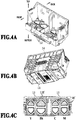
- Fig. 4A is a perspective view of the main body part 10 in which the front side thereof is recognizable
- Fig. 4B is a perspective view of the main body part 10 in which the back side thereof is recognizable
- Fig. 4C is a top view of the main body part 10.
- the main body part 10 has a box shape. The top and the front of the main body part 10 are open while the back, the bottom, and both lateral sides of the main body part 10 are walls.
- the bottom of the main body part 10 refers to the portion to which the sub-tank 20 is attached (fixed).
- An ejection unit 11 is connected to the outside of the bottom portion, and filters 12 configured to prevent entrance of dust and the like are provided on the inside of the bottom portion.
- the outside of the bottom portion refers to the face opposite to the bottom of the main body part 10.
- the inside of the bottom portion refers to the face on the side of the bottom of the main body part 10 to which the sub-tank 20 is attached.
- the filter 12 corresponding to the black (Bk) ink has a hexagonal shape, and the ones corresponding to the inks of the other colors, which are cyan (C), magenta (M), and yellow (Y), have pentagonal shapes.
- Later-described inner flow passages capable of supplying the inks from the filter portions to the ejection unit 11 are formed in an interior of the bottom portion of the main body part 10.
- An electric wiring board 14 for electrical connection with a main body of the liquid ejecting apparatus 1 is provided on the outside of the back of the main body part 10.
- Fig. 5A is a perspective view of the liquid ejecting head 5, and Fig. 5B is a cross-sectional view along the line Vb-Vb in Fig. 5A .
- the ink is supplied from the supply source 6 to an ink chamber 24 in the sub-tank 20 via the supply tube 4 through a joint portion 21.
- the elastic member 30 forms a seal between the filter 12 of the main body part 10 and the ink chamber 24 of the sub-tank 20, and the ink supplied to the ink chamber 24 passes the filter 12 of the main body part 10 and is supplied to the ejection unit 11 via an inner flow passage 13.
- a joint needle 23 made of a resin is provided at a front end of the supply tube 4, and a joint sealing member 22 is attached to the joint portion 21 of the sub-tank 20.
- the joint needle 23 is inserted into the joint sealing member 22 and sealed, and thereby the supply tube 4 and the ink chamber 24 of the sub-tank 20 are connected to each other.
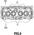
- Fig. 6 is a top view of the liquid ejecting head 5.
- the sub-tank 20 is attached to the main body part 10 by using the multiple screws 25 as described above.
- the main body part 10 has a box shape, and the top and the front of the main body part 10 are open while the back, the bottom, and both lateral sides of the main body part 10 are walls.
- the sub-tank 20 is attached to the bottom of the main body part 10, and the stiffness of the bottom of the main body part 10 is different depending on the position due to the shape of the main body part 10. Specifically, since the front of the main body part 10 is open and has no wall standing from the bottom, the stiffness of the bottom is low in a front side center portion (second region).
- the stiffness of the bottom is high in sections (first region) on the back side and the lateral sides that are adjacent to the walls.
- the second region refers to a region extending along an edge where no wall is formed.
- the region extending along the edge where no wall is formed refers to a region extending from the edge where no wall is formed and having one-fifth the entire length of the rectangular shape in the direction orthogonal to the edge.
- the first region refers to the region other than the aforementioned second region in the bottom of the main body part 10.
- a greater number of screws 25 are used in a front side region of the bottom where the stiffness is low, and a smaller number of screws 25 are used in a back side region of the bottom where the stiffness is high.
- the sub-tank 20 is fixed with four screws 25 on the front side and with two screws 25 on the back side.
- the sub-tank 20 can be fixed to a portion of the bottom with high stiffness with a smaller number of the screws 25.
- Determining the arrangement (number) of the screws 25 for the attachment of the sub-tank 20 based on the distribution of the stiffness of the bottom as in the present invention enables attachment of the sub-tank 20 with a small number of screws 25 while suppressing the deformation of the bottom of the main body part 10. This configuration suppresses increase in cost and decrease in productivity.
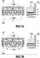
- Figs. 7A and 7B are diagrams for comparing the main body part 10 on which the sub-tank 20 is attached.
- Fig. 7A illustrates a comparative example for the embodiment and shows a top view and a cross-sectional view of the main body part 10 to which the sub-tank 20 is fixed with two screws 25 on the front side and with two screws 25 on the back side.
- Fig. 7B shows a top view and a cross-sectional view of the main body part 10 of the embodiment illustrated in Fig. 6 .
- the front side center portion of the bottom is not fixed to the sub-tank 20. Accordingly, as illustrated in the cross-section VIIa-VIIa of Fig. 7A , the center portion of the bottom with low stiffness receives an effect of reaction force of the elastic member 30 and deforms. Along with this deformation, there is a possibility that the ejection unit 11 attached on the outside of the bottom of the main body part 10 deforms, decreasing ejection accuracy.
- the center portion of the bottom is also fixed to the sub-tank 20 with the screws 25.
- the center portion of the bottom thus conforms to the sub-tank 20 and the deformation of the bottom can be thereby suppressed.
- the four screws 25 on the front side are arranged at positions 4 mm and 44 mm from the center to the left in Fig. 7B and at positions 8 mm and 44 mm from the center to the right in Fig. 7B .
- the two left and right screws 25 arranged on the back side are each arranged approximately at the middle of the corresponding two screws on the front side, and thus the screws 25 are arranged in a triangular shape on each of the left side and the right side of the sub-tank 20.
- the screws 25 on the back side are arranged at a position 24 mm from the center to the left in Fig. 7B and at a position 26 mm from the center to the right in Fig. 7B .
- the sub-tank 20 is attached to the bottom of the main body part 10 by using a greater number of screws 25 on the front side where the stiffness is low than that on the back side where the stiffness is high. Accordingly, it is possible to provide a liquid ejecting head and a liquid ejecting apparatus that can suppress decrease in ejection accuracy while suppressing increase in cost and decrease in productivity.
- Fig. 8 is a top view of the liquid ejecting head 5 of the embodiment.
- the number of screws 25 for the attachment of the sub-tank 20 to the main body part 10 may be three on the front side and two on the back side.
- the three screws 25 on the front side are arranged in the center portion and at the left and right ends.
- the screws 25 arranged on the back side are at the same positions as those in the first embodiment. Such arrangement of the screws 25 can also suppress the deformation of the main body part 10.
- Figs. 9A and 9B are a top view and a front view of the liquid ejecting head 5 of the embodiment.
- Fig. 9A is the top view
- Fig. 9B is the front view.
- the screws 25 for the attachment are illustrated while the sub-tank 20 is omitted to make the main body part 10 more recognizable.
- the main body part 10 in the embodiment has no wall on the back side and has walls on the both lateral sides. Specifically, the stiffness of the bottom of the main body part 10 is high in regions adjacent to the both end portions provided with the walls and is low in regions adjacent to the center portion where no wall is provided.
- the sub-tank 20 is fixed with one screw 25 in each of the end portions of the main body part 10 with high stiffness and with four screws 25 in the center portion with low stiffness. Determining the arrangement of the screws 25 according to the stiffness of the bottom as described above can suppress deformation of the main body part 10.
Landscapes
- Ink Jet (AREA)
Abstract
Description
- The present invention relates to a liquid ejecting head configured to eject liquid and a liquid ejecting apparatus.
- As described in
Japanese Patent Laid-Open No. 2016-5893 -
Japanese Patent Laid-Open No. 2016-5893 - However, in the case where the material of the sub-tank has a higher stiffness than the material of the main body part in a configuration like that of
Japanese Patent Laid-Open No. 2016-5893 - A conceivable method to avoid the above situation is to increase the number of screws used to fix the sub-tank and ensure that the main body part conforms to the sub-tank. In
Japanese Patent Laid-Open No. 2016-5893 - The present invention in its first aspect provides a liquid ejecting head and a liquid ejecting apparatus as specified in
claims 1 to 4 and claims 6 to 9. - The present invention in its second aspect provides a liquid ejecting head and a liquid ejecting apparatus as specified in
claim 5. - Further features of the present invention will become apparent from the following description of exemplary embodiments with reference to the attached drawings.
-
-
Fig. 1 is a schematic view of a liquid ejecting apparatus; -
Fig. 2 is a perspective view of a liquid ejecting head; -
Fig. 3 is an exploded perspective view of the liquid ejecting head; -
Fig. 4A is a view of a main body part; -
Fig. 4B is a view of the main body part; -
Fig. 4C is a view of the main body part; -
Fig. 5A is a view of the liquid ejecting head; -
Fig. 5B is a view of the liquid ejecting head; -
Fig. 6 is a top view of the liquid ejecting head; -
Fig. 7A is a view of a main body part to which a sub-tank is attached; -
Fig. 7B is a view of a main body part to which a sub-tank is attached; -
Fig. 8 is a top view of a liquid ejecting head; -
Fig. 9A is a view of a liquid ejecting head; and -
Fig. 9B is a view of the liquid ejecting head. - A first embodiment of the present invention is described below with reference to the drawings.
-
Fig. 1 is a schematic view of a liquid ejectingapparatus 1 to which the present invention can be applied. The liquid ejectingapparatus 1 includes a liquid ejectinghead 5 configured to eject liquid (hereinafter, also referred to as ink), a carriage 3 which is movable along guide rails 2 and on which the liquid ejectinghead 5 is mountable, and a supply source 6 configured to supply the liquid to the liquid ejectinghead 5 viasupply tubes 4. The liquid ejectinghead 5 ejects the liquid to a medium 8 being conveyed to perform printing on the medium 8. Multiple ejection ports are provided in the liquid ejectinghead 5, and the ink is ejected from the ejection ports by driving actuators such as heaters. - The supply source 6 includes ink storage chambers 7 provided independently for the respective ink colors. In the embodiment, the supply source 6 includes the ink storage chambers 7 for four colors of black (Bk), cyan (C), magenta (M), and yellow (Y). Each ink storage chamber 7 includes a connection port connected to the outside and is configured such that ink can be directly added to the ink storage chamber 7 from the outside. The supply source 6 may be replaceable ink tanks.
-
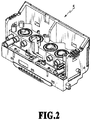
Fig. 2 is a perspective view of the liquid ejectinghead 5, andFig. 3 is an exploded perspective view of the liquid ejectinghead 5. The liquid ejectinghead 5 includes a box-shapedmain body part 10 and a sub-tank (tank) 20 that is attached to themain body part 10 and that is capable of storing the liquid.Elastic members 30 are provided between themain body part 10 and thesub-tank 20 and form seals between themain body part 10 and thesub-tank 20. Thesub-tank 20 is fixed to themain body part 10 withmultiple screws 25. Themain body part 10 is made of a non-filler resin material and has low stiffness. Thesub-tank 20 is made of a resin material containing filler and has high stiffness. -
Fig. 4A is a perspective view of themain body part 10 in which the front side thereof is recognizable, andFig. 4B is a perspective view of themain body part 10 in which the back side thereof is recognizable.Fig. 4C is a top view of themain body part 10. Themain body part 10 has a box shape. The top and the front of themain body part 10 are open while the back, the bottom, and both lateral sides of themain body part 10 are walls. In this case, the bottom of themain body part 10 refers to the portion to which thesub-tank 20 is attached (fixed). Anejection unit 11 is connected to the outside of the bottom portion, andfilters 12 configured to prevent entrance of dust and the like are provided on the inside of the bottom portion. The outside of the bottom portion refers to the face opposite to the bottom of themain body part 10. - The inside of the bottom portion refers to the face on the side of the bottom of the
main body part 10 to which the sub-tank 20 is attached. Thefilter 12 corresponding to the black (Bk) ink has a hexagonal shape, and the ones corresponding to the inks of the other colors, which are cyan (C), magenta (M), and yellow (Y), have pentagonal shapes. Later-described inner flow passages capable of supplying the inks from the filter portions to theejection unit 11 are formed in an interior of the bottom portion of themain body part 10. Anelectric wiring board 14 for electrical connection with a main body of theliquid ejecting apparatus 1 is provided on the outside of the back of themain body part 10. -
Fig. 5A is a perspective view of theliquid ejecting head 5, andFig. 5B is a cross-sectional view along the line Vb-Vb inFig. 5A . The ink is supplied from the supply source 6 to anink chamber 24 in the sub-tank 20 via thesupply tube 4 through ajoint portion 21. Theelastic member 30 forms a seal between thefilter 12 of themain body part 10 and theink chamber 24 of the sub-tank 20, and the ink supplied to theink chamber 24 passes thefilter 12 of themain body part 10 and is supplied to theejection unit 11 via aninner flow passage 13. Ajoint needle 23 made of a resin is provided at a front end of thesupply tube 4, and ajoint sealing member 22 is attached to thejoint portion 21 of the sub-tank 20. Thejoint needle 23 is inserted into the joint sealingmember 22 and sealed, and thereby thesupply tube 4 and theink chamber 24 of the sub-tank 20 are connected to each other. -
Fig. 6 is a top view of theliquid ejecting head 5. The sub-tank 20 is attached to themain body part 10 by using themultiple screws 25 as described above. - In this case, as described also in
Figs. 4A to 4C , themain body part 10 has a box shape, and the top and the front of themain body part 10 are open while the back, the bottom, and both lateral sides of themain body part 10 are walls. The sub-tank 20 is attached to the bottom of themain body part 10, and the stiffness of the bottom of themain body part 10 is different depending on the position due to the shape of themain body part 10. Specifically, since the front of themain body part 10 is open and has no wall standing from the bottom, the stiffness of the bottom is low in a front side center portion (second region). - In contrast, since the back and the lateral sides of the
main body part 10 have walls standing from the end portions of the bottom, the stiffness of the bottom is high in sections (first region) on the back side and the lateral sides that are adjacent to the walls. In the case where the bottom of themain body part 10 is assumed to have a rectangular shape, the second region refers to a region extending along an edge where no wall is formed. In this case, the region extending along the edge where no wall is formed refers to a region extending from the edge where no wall is formed and having one-fifth the entire length of the rectangular shape in the direction orthogonal to the edge. The first region refers to the region other than the aforementioned second region in the bottom of themain body part 10. - Accordingly, in the embodiment, in the attachment of the sub-tank 20 to the bottom of the
main body part 10, a greater number ofscrews 25 are used in a front side region of the bottom where the stiffness is low, and a smaller number ofscrews 25 are used in a back side region of the bottom where the stiffness is high. Specifically, the sub-tank 20 is fixed with fourscrews 25 on the front side and with twoscrews 25 on the back side. - Using a greater number of the
screws 25 on the front side as described above for fixing the sub-tank 20 makes a portion of the bottom with low stiffness conform to the sub-tank 20 with high stiffness. On the back side, the sub-tank 20 can be fixed to a portion of the bottom with high stiffness with a smaller number of thescrews 25. - Determining the arrangement (number) of the
screws 25 for the attachment of the sub-tank 20 based on the distribution of the stiffness of the bottom as in the present invention enables attachment of the sub-tank 20 with a small number ofscrews 25 while suppressing the deformation of the bottom of themain body part 10. This configuration suppresses increase in cost and decrease in productivity. -
Figs. 7A and 7B are diagrams for comparing themain body part 10 on which the sub-tank 20 is attached.Fig. 7A illustrates a comparative example for the embodiment and shows a top view and a cross-sectional view of themain body part 10 to which the sub-tank 20 is fixed with twoscrews 25 on the front side and with twoscrews 25 on the back side.Fig. 7B shows a top view and a cross-sectional view of themain body part 10 of the embodiment illustrated inFig. 6 . - As illustrated in
Fig. 7A , in the case where the front side center portion is not fixed with screws, and both end portions on the front side are fixed with twoscrews 25, the front side center portion of the bottom is not fixed to the sub-tank 20. Accordingly, as illustrated in the cross-section VIIa-VIIa ofFig. 7A , the center portion of the bottom with low stiffness receives an effect of reaction force of theelastic member 30 and deforms. Along with this deformation, there is a possibility that theejection unit 11 attached on the outside of the bottom of themain body part 10 deforms, decreasing ejection accuracy. - In contrast, as in the embodiment illustrated in
Fig. 7B , in the case where the sub-tank 20 is attached to themain body part 10 by fixing the front side with fourscrews 25, the number of which is greater than the number ofscrews 25 on the back side, the center portion of the bottom is also fixed to the sub-tank 20 with thescrews 25. The center portion of the bottom thus conforms to the sub-tank 20 and the deformation of the bottom can be thereby suppressed. - The four
screws 25 on the front side are arranged atpositions 4 mm and 44 mm from the center to the left inFig. 7B and at positions 8 mm and 44 mm from the center to the right inFig. 7B . The two left andright screws 25 arranged on the back side are each arranged approximately at the middle of the corresponding two screws on the front side, and thus thescrews 25 are arranged in a triangular shape on each of the left side and the right side of the sub-tank 20. Specifically, thescrews 25 on the back side are arranged at aposition 24 mm from the center to the left inFig. 7B and at a position 26 mm from the center to the right inFig. 7B . - As described above, the sub-tank 20 is attached to the bottom of the
main body part 10 by using a greater number ofscrews 25 on the front side where the stiffness is low than that on the back side where the stiffness is high. Accordingly, it is possible to provide a liquid ejecting head and a liquid ejecting apparatus that can suppress decrease in ejection accuracy while suppressing increase in cost and decrease in productivity. - A second embodiment of the present embodiment is described below with reference to the drawings. Note that, since the basic configuration of the embodiment is the same as that of the first embodiment, characteristic configurations are described below.
-
Fig. 8 is a top view of theliquid ejecting head 5 of the embodiment. The number ofscrews 25 for the attachment of the sub-tank 20 to themain body part 10 may be three on the front side and two on the back side. The threescrews 25 on the front side are arranged in the center portion and at the left and right ends. Thescrews 25 arranged on the back side are at the same positions as those in the first embodiment. Such arrangement of thescrews 25 can also suppress the deformation of themain body part 10. - Other embodiments of the present invention are described below with reference to the drawings. Note that, since the basic configuration of the embodiment is the same as that of the first embodiment, characteristic configurations are described below.
-
Figs. 9A and 9B are a top view and a front view of theliquid ejecting head 5 of the embodiment.Fig. 9A is the top view, andFig. 9B is the front view. InFig. 9B , thescrews 25 for the attachment are illustrated while the sub-tank 20 is omitted to make themain body part 10 more recognizable. Themain body part 10 in the embodiment has no wall on the back side and has walls on the both lateral sides. Specifically, the stiffness of the bottom of themain body part 10 is high in regions adjacent to the both end portions provided with the walls and is low in regions adjacent to the center portion where no wall is provided. Accordingly, in the embodiment, the sub-tank 20 is fixed with onescrew 25 in each of the end portions of themain body part 10 with high stiffness and with fourscrews 25 in the center portion with low stiffness. Determining the arrangement of thescrews 25 according to the stiffness of the bottom as described above can suppress deformation of themain body part 10. - While the present invention has been described with reference to exemplary embodiments, it is to be understood that the invention is not limited to the disclosed exemplary embodiments. The scope of the following claims is to be accorded the broadest interpretation so as to encompass all such modifications and equivalent structures and functions.
Claims (9)
- A liquid ejecting head (5) comprising:a tank (20) capable of storing liquid;a main body part (10) to which the tank (20) is attached; andan elastic member (30) provided between the tank (20) and the main body part (10) and forming a seal between the tank (20) and the main body part (10), whereina bottom of the main body part (10) includes a first region adjacent to a region provided with a wall standing from an end portion of the bottom and a second region adjacent to a region not provided with the wall,the tank (20) is attached to the bottom of the main body part (10) by using screws (25) attached to the first region and the second region, andthe number of the screws (25) attached to the second region is greater than the number of the screws (25) attached to the first region.
- The liquid ejecting head (5) according to claim 1, wherein
the tank (20) is formed of a resin, and
the main body part (10) is formed of a resin with a lower stiffness than the resin forming the tank (20). - The liquid ejecting head (5) according to claim 1 or 2, wherein
the main body part (10) has a box shape, and
the main body part (10) has the wall at a back and both lateral sides of the box shape and does not have the wall at a front and a top of the box shape. - The liquid ejecting head (5) according to claim 3, wherein the tank (20) is attached to the bottom by using four of the screws (25) on the front side of the box shape and two of the screws (25) on the back side of the box shape.
- The liquid ejecting head (5) according to claim 3, wherein the tank (20) is attached to the bottom by using three of the screws (25) on the front side of the box shape and two of the screws (25) on the back side of the box shape.
- The liquid ejecting head (5) according to any one of claims 1 to 5, further comprising an ejection unit provided on the outside of the bottom and configured to eject the liquid.
- The liquid ejecting head (5) according to claim 6, wherein a flow passage capable of supplying the liquid to the ejection unit is provided in the bottom.
- The liquid ejecting head (5) according to any one of claims 1 to 7, further comprising a filter (12) provided on the bottom between the tank (20) and the main body part (10) and configured to prevent entrance of dust into the main body part (10).
- A liquid ejecting apparatus (1) comprising
a liquid ejecting head (5) including a tank (20) capable of storing liquid, a main body part (10) to which the tank (20) is attached, and an elastic member (30) provided between the tank (20) and the main body part (10) and forming a seal between the tank (20) and the main body part (10), wherein
a bottom of the main body part (10) includes a first region adjacent to a region provided with a wall standing from an end portion of the bottom and a second region adjacent to a region not provided with the wall,
the tank (20) is attached to the bottom of the main body part (10) by using screws (25) attached to the first region and the second region, and
the number of the screws (25) attached to the second region is greater than the number of the screws (25) attached to the first region.
Applications Claiming Priority (1)
| Application Number | Priority Date | Filing Date | Title |
|---|---|---|---|
| JP2020118709A JP7471941B2 (en) | 2020-07-09 | 2020-07-09 | LIQUID EJECTION HEAD AND LIQUID EJECTION APPARATUS |
Publications (2)
| Publication Number | Publication Date |
|---|---|
| EP3936344A1 true EP3936344A1 (en) | 2022-01-12 |
| EP3936344B1 EP3936344B1 (en) | 2024-03-27 |
Family
ID=76553608
Family Applications (1)
| Application Number | Title | Priority Date | Filing Date |
|---|---|---|---|
| EP21180875.3A Active EP3936344B1 (en) | 2020-07-09 | 2021-06-22 | Liquid ejecting head and liquid ejecting apparatus |
Country Status (4)
| Country | Link |
|---|---|
| US (1) | US11787189B2 (en) |
| EP (1) | EP3936344B1 (en) |
| JP (1) | JP7471941B2 (en) |
| CN (1) | CN113910768B (en) |
Citations (9)
| Publication number | Priority date | Publication date | Assignee | Title |
|---|---|---|---|---|
| EP1231065A2 (en) * | 2001-02-09 | 2002-08-14 | Canon Kabushiki Kaisha | Pressure adjustment chamber, ink-jet recording head having the same, and ink-jet recording device using the same |
| US20120038708A1 (en) * | 2010-08-12 | 2012-02-16 | Seiko Epson Corporation | Liquid ejecting apparatus |
| US8434852B2 (en) * | 2010-07-09 | 2013-05-07 | Seiko Epson Corporation | Liquid ejecting head unit and liquid ejecting apparatus |
| US8491109B2 (en) * | 2011-01-14 | 2013-07-23 | Seiko Epson Corporation | Container unit and liquid ejection system |
| US9061497B2 (en) * | 2013-02-22 | 2015-06-23 | Seiko Epson Corporation | Liquid ejecting head and liquid ejecting apparatus |
| US20150251435A1 (en) * | 2014-03-04 | 2015-09-10 | Seiko Epson Corporation | Liquid ejecting head and liquid ejecting apparatus |
| JP2016005893A (en) | 2014-05-30 | 2016-01-14 | キヤノン株式会社 | Liquid ejecting head and fabricating method for liquid ejecting head |
| US20160347076A1 (en) * | 2015-05-29 | 2016-12-01 | Canon Kabushiki Kaisha | Liquid ejection apparatus and attachment assembly of liquid ejection apparatus |
| US10471727B2 (en) * | 2015-05-22 | 2019-11-12 | Canon Kabushiki Kaisha | Liquid ejecting head and liquid ejecting apparatus |
Family Cites Families (8)
| Publication number | Priority date | Publication date | Assignee | Title |
|---|---|---|---|---|
| ATE358589T1 (en) | 2003-12-04 | 2007-04-15 | Brother Ind Ltd | INKJET PRINT HEAD AND INKJET PRINTER |
| JP4471083B2 (en) | 2003-12-22 | 2010-06-02 | ブラザー工業株式会社 | Inkjet printer |
| JP2010069746A (en) | 2008-09-19 | 2010-04-02 | Brother Ind Ltd | Liquid discharge head |
| JP5510178B2 (en) | 2010-08-18 | 2014-06-04 | セイコーエプソン株式会社 | Liquid ejecting head unit and liquid ejecting apparatus |
| JP6415114B2 (en) | 2014-05-30 | 2018-10-31 | キヤノン株式会社 | Liquid storage unit, liquid discharge apparatus using the same, and method for removing bubbles from liquid storage unit |
| JP2016215545A (en) | 2015-05-22 | 2016-12-22 | キヤノン株式会社 | Liquid discharge head and liquid discharge device |
| JP6541436B2 (en) | 2015-05-27 | 2019-07-10 | キヤノン株式会社 | Liquid discharge head and liquid discharge device |
| JP7467090B2 (en) | 2019-12-05 | 2024-04-15 | キヤノン株式会社 | Liquid ejection head |
-
2020
- 2020-07-09 JP JP2020118709A patent/JP7471941B2/en active Active
-
2021
- 2021-06-16 US US17/348,906 patent/US11787189B2/en active Active
- 2021-06-22 EP EP21180875.3A patent/EP3936344B1/en active Active
- 2021-07-06 CN CN202110759476.3A patent/CN113910768B/en active Active
Patent Citations (9)
| Publication number | Priority date | Publication date | Assignee | Title |
|---|---|---|---|---|
| EP1231065A2 (en) * | 2001-02-09 | 2002-08-14 | Canon Kabushiki Kaisha | Pressure adjustment chamber, ink-jet recording head having the same, and ink-jet recording device using the same |
| US8434852B2 (en) * | 2010-07-09 | 2013-05-07 | Seiko Epson Corporation | Liquid ejecting head unit and liquid ejecting apparatus |
| US20120038708A1 (en) * | 2010-08-12 | 2012-02-16 | Seiko Epson Corporation | Liquid ejecting apparatus |
| US8491109B2 (en) * | 2011-01-14 | 2013-07-23 | Seiko Epson Corporation | Container unit and liquid ejection system |
| US9061497B2 (en) * | 2013-02-22 | 2015-06-23 | Seiko Epson Corporation | Liquid ejecting head and liquid ejecting apparatus |
| US20150251435A1 (en) * | 2014-03-04 | 2015-09-10 | Seiko Epson Corporation | Liquid ejecting head and liquid ejecting apparatus |
| JP2016005893A (en) | 2014-05-30 | 2016-01-14 | キヤノン株式会社 | Liquid ejecting head and fabricating method for liquid ejecting head |
| US10471727B2 (en) * | 2015-05-22 | 2019-11-12 | Canon Kabushiki Kaisha | Liquid ejecting head and liquid ejecting apparatus |
| US20160347076A1 (en) * | 2015-05-29 | 2016-12-01 | Canon Kabushiki Kaisha | Liquid ejection apparatus and attachment assembly of liquid ejection apparatus |
Also Published As
| Publication number | Publication date |
|---|---|
| US11787189B2 (en) | 2023-10-17 |
| CN113910768A (en) | 2022-01-11 |
| US20220009237A1 (en) | 2022-01-13 |
| EP3936344B1 (en) | 2024-03-27 |
| JP7471941B2 (en) | 2024-04-22 |
| JP2022015694A (en) | 2022-01-21 |
| CN113910768B (en) | 2023-09-15 |
Similar Documents
| Publication | Publication Date | Title |
|---|---|---|
| US8057015B2 (en) | Liquid ejecting head unit and liquid ejecting apparatus | |
| US8277033B2 (en) | Liquid-drop ejecting apparatus and liquid cartridge | |
| US10449772B2 (en) | Cartridge and liquid ejection system | |
| US20070263053A1 (en) | Ink-jet recording apparatus | |
| US11198305B2 (en) | Liquid jetting head | |
| JP4153915B2 (en) | ink cartridge | |
| US9962946B2 (en) | Liquid ejecting system | |
| US11787189B2 (en) | Liquid ejecting head and liquid ejecting apparatus | |
| US10486426B2 (en) | Cartridge and liquid supply unit | |
| US20110157274A1 (en) | Liquid supply apparatus and printer | |
| US9694589B1 (en) | Ink cartridge | |
| US9636917B2 (en) | Liquid supply unit | |
| JP5875288B2 (en) | Liquid ejector | |
| CN207955013U (en) | Ink-jet printer | |
| JP5842604B2 (en) | Ink supply apparatus and image recording apparatus | |
| EP4344881A1 (en) | Cartridge, system, and cartridge set | |
| CN113135042B (en) | Liquid ejecting apparatus | |
| CN211808466U (en) | Ink-injection cylinder, ink tank and ink-jet printer | |
| JP5842605B2 (en) | Refill case | |
| CN207955028U (en) | Ink-jet printer | |
| CN207955027U (en) | Ink-jet printer | |
| WO2022071118A1 (en) | Liquid supplying apparatus | |
| US7549736B2 (en) | Printhead assembly having ink flow channels to accommodate offset chips | |
| CN121799058A (en) | Liquid container and image forming apparatus | |
| JP2020111033A (en) | system |
Legal Events
| Date | Code | Title | Description |
|---|---|---|---|
| PUAI | Public reference made under article 153(3) epc to a published international application that has entered the european phase |
Free format text: ORIGINAL CODE: 0009012 |
|
| STAA | Information on the status of an ep patent application or granted ep patent |
Free format text: STATUS: THE APPLICATION HAS BEEN PUBLISHED |
|
| AK | Designated contracting states |
Kind code of ref document: A1 Designated state(s): AL AT BE BG CH CY CZ DE DK EE ES FI FR GB GR HR HU IE IS IT LI LT LU LV MC MK MT NL NO PL PT RO RS SE SI SK SM TR |
|
| B565 | Issuance of search results under rule 164(2) epc |
Effective date: 20211208 |
|
| STAA | Information on the status of an ep patent application or granted ep patent |
Free format text: STATUS: REQUEST FOR EXAMINATION WAS MADE |
|
| 17P | Request for examination filed |
Effective date: 20220330 |
|
| RBV | Designated contracting states (corrected) |
Designated state(s): AL AT BE BG CH CY CZ DE DK EE ES FI FR GB GR HR HU IE IS IT LI LT LU LV MC MK MT NL NO PL PT RO RS SE SI SK SM TR |
|
| GRAP | Despatch of communication of intention to grant a patent |
Free format text: ORIGINAL CODE: EPIDOSNIGR1 |
|
| STAA | Information on the status of an ep patent application or granted ep patent |
Free format text: STATUS: GRANT OF PATENT IS INTENDED |
|
| INTG | Intention to grant announced |
Effective date: 20231113 |
|
| GRAS | Grant fee paid |
Free format text: ORIGINAL CODE: EPIDOSNIGR3 |
|
| GRAA | (expected) grant |
Free format text: ORIGINAL CODE: 0009210 |
|
| STAA | Information on the status of an ep patent application or granted ep patent |
Free format text: STATUS: THE PATENT HAS BEEN GRANTED |
|
| AK | Designated contracting states |
Kind code of ref document: B1 Designated state(s): AL AT BE BG CH CY CZ DE DK EE ES FI FR GB GR HR HU IE IS IT LI LT LU LV MC MK MT NL NO PL PT RO RS SE SI SK SM TR |
|
| REG | Reference to a national code |
Ref country code: GB Ref legal event code: FG4D |
|
| REG | Reference to a national code |
Ref country code: CH Ref legal event code: EP |
|
| REG | Reference to a national code |
Ref country code: DE Ref legal event code: R096 Ref document number: 602021010838 Country of ref document: DE |
|
| REG | Reference to a national code |
Ref country code: IE Ref legal event code: FG4D |
|
| PG25 | Lapsed in a contracting state [announced via postgrant information from national office to epo] |
Ref country code: LT Free format text: LAPSE BECAUSE OF FAILURE TO SUBMIT A TRANSLATION OF THE DESCRIPTION OR TO PAY THE FEE WITHIN THE PRESCRIBED TIME-LIMIT Effective date: 20240327 |
|
| REG | Reference to a national code |
Ref country code: LT Ref legal event code: MG9D |
|
| PG25 | Lapsed in a contracting state [announced via postgrant information from national office to epo] |
Ref country code: GR Free format text: LAPSE BECAUSE OF FAILURE TO SUBMIT A TRANSLATION OF THE DESCRIPTION OR TO PAY THE FEE WITHIN THE PRESCRIBED TIME-LIMIT Effective date: 20240628 |
|
| PG25 | Lapsed in a contracting state [announced via postgrant information from national office to epo] |
Ref country code: RS Free format text: LAPSE BECAUSE OF FAILURE TO SUBMIT A TRANSLATION OF THE DESCRIPTION OR TO PAY THE FEE WITHIN THE PRESCRIBED TIME-LIMIT Effective date: 20240627 Ref country code: HR Free format text: LAPSE BECAUSE OF FAILURE TO SUBMIT A TRANSLATION OF THE DESCRIPTION OR TO PAY THE FEE WITHIN THE PRESCRIBED TIME-LIMIT Effective date: 20240327 |
|
| PG25 | Lapsed in a contracting state [announced via postgrant information from national office to epo] |
Ref country code: RS Free format text: LAPSE BECAUSE OF FAILURE TO SUBMIT A TRANSLATION OF THE DESCRIPTION OR TO PAY THE FEE WITHIN THE PRESCRIBED TIME-LIMIT Effective date: 20240627 Ref country code: NO Free format text: LAPSE BECAUSE OF FAILURE TO SUBMIT A TRANSLATION OF THE DESCRIPTION OR TO PAY THE FEE WITHIN THE PRESCRIBED TIME-LIMIT Effective date: 20240627 Ref country code: LT Free format text: LAPSE BECAUSE OF FAILURE TO SUBMIT A TRANSLATION OF THE DESCRIPTION OR TO PAY THE FEE WITHIN THE PRESCRIBED TIME-LIMIT Effective date: 20240327 Ref country code: HR Free format text: LAPSE BECAUSE OF FAILURE TO SUBMIT A TRANSLATION OF THE DESCRIPTION OR TO PAY THE FEE WITHIN THE PRESCRIBED TIME-LIMIT Effective date: 20240327 Ref country code: GR Free format text: LAPSE BECAUSE OF FAILURE TO SUBMIT A TRANSLATION OF THE DESCRIPTION OR TO PAY THE FEE WITHIN THE PRESCRIBED TIME-LIMIT Effective date: 20240628 Ref country code: FI Free format text: LAPSE BECAUSE OF FAILURE TO SUBMIT A TRANSLATION OF THE DESCRIPTION OR TO PAY THE FEE WITHIN THE PRESCRIBED TIME-LIMIT Effective date: 20240327 Ref country code: BG Free format text: LAPSE BECAUSE OF FAILURE TO SUBMIT A TRANSLATION OF THE DESCRIPTION OR TO PAY THE FEE WITHIN THE PRESCRIBED TIME-LIMIT Effective date: 20240327 |
|
| REG | Reference to a national code |
Ref country code: NL Ref legal event code: MP Effective date: 20240327 |
|
| PG25 | Lapsed in a contracting state [announced via postgrant information from national office to epo] |
Ref country code: SE Free format text: LAPSE BECAUSE OF FAILURE TO SUBMIT A TRANSLATION OF THE DESCRIPTION OR TO PAY THE FEE WITHIN THE PRESCRIBED TIME-LIMIT Effective date: 20240327 Ref country code: LV Free format text: LAPSE BECAUSE OF FAILURE TO SUBMIT A TRANSLATION OF THE DESCRIPTION OR TO PAY THE FEE WITHIN THE PRESCRIBED TIME-LIMIT Effective date: 20240327 |
|
| PG25 | Lapsed in a contracting state [announced via postgrant information from national office to epo] |
Ref country code: NL Free format text: LAPSE BECAUSE OF FAILURE TO SUBMIT A TRANSLATION OF THE DESCRIPTION OR TO PAY THE FEE WITHIN THE PRESCRIBED TIME-LIMIT Effective date: 20240327 |
|
| REG | Reference to a national code |
Ref country code: AT Ref legal event code: MK05 Ref document number: 1669562 Country of ref document: AT Kind code of ref document: T Effective date: 20240327 |
|
| PG25 | Lapsed in a contracting state [announced via postgrant information from national office to epo] |
Ref country code: NL Free format text: LAPSE BECAUSE OF FAILURE TO SUBMIT A TRANSLATION OF THE DESCRIPTION OR TO PAY THE FEE WITHIN THE PRESCRIBED TIME-LIMIT Effective date: 20240327 |
|
| PG25 | Lapsed in a contracting state [announced via postgrant information from national office to epo] |
Ref country code: IS Free format text: LAPSE BECAUSE OF FAILURE TO SUBMIT A TRANSLATION OF THE DESCRIPTION OR TO PAY THE FEE WITHIN THE PRESCRIBED TIME-LIMIT Effective date: 20240727 |
|
| PG25 | Lapsed in a contracting state [announced via postgrant information from national office to epo] |
Ref country code: PT Free format text: LAPSE BECAUSE OF FAILURE TO SUBMIT A TRANSLATION OF THE DESCRIPTION OR TO PAY THE FEE WITHIN THE PRESCRIBED TIME-LIMIT Effective date: 20240729 Ref country code: SM Free format text: LAPSE BECAUSE OF FAILURE TO SUBMIT A TRANSLATION OF THE DESCRIPTION OR TO PAY THE FEE WITHIN THE PRESCRIBED TIME-LIMIT Effective date: 20240327 |
|
| PG25 | Lapsed in a contracting state [announced via postgrant information from national office to epo] |
Ref country code: ES Free format text: LAPSE BECAUSE OF FAILURE TO SUBMIT A TRANSLATION OF THE DESCRIPTION OR TO PAY THE FEE WITHIN THE PRESCRIBED TIME-LIMIT Effective date: 20240327 |
|
| PG25 | Lapsed in a contracting state [announced via postgrant information from national office to epo] |
Ref country code: CZ Free format text: LAPSE BECAUSE OF FAILURE TO SUBMIT A TRANSLATION OF THE DESCRIPTION OR TO PAY THE FEE WITHIN THE PRESCRIBED TIME-LIMIT Effective date: 20240327 Ref country code: EE Free format text: LAPSE BECAUSE OF FAILURE TO SUBMIT A TRANSLATION OF THE DESCRIPTION OR TO PAY THE FEE WITHIN THE PRESCRIBED TIME-LIMIT Effective date: 20240327 |
|
| PG25 | Lapsed in a contracting state [announced via postgrant information from national office to epo] |
Ref country code: AT Free format text: LAPSE BECAUSE OF FAILURE TO SUBMIT A TRANSLATION OF THE DESCRIPTION OR TO PAY THE FEE WITHIN THE PRESCRIBED TIME-LIMIT Effective date: 20240327 |
|
| PG25 | Lapsed in a contracting state [announced via postgrant information from national office to epo] |
Ref country code: PL Free format text: LAPSE BECAUSE OF FAILURE TO SUBMIT A TRANSLATION OF THE DESCRIPTION OR TO PAY THE FEE WITHIN THE PRESCRIBED TIME-LIMIT Effective date: 20240327 |
|
| PG25 | Lapsed in a contracting state [announced via postgrant information from national office to epo] |
Ref country code: SK Free format text: LAPSE BECAUSE OF FAILURE TO SUBMIT A TRANSLATION OF THE DESCRIPTION OR TO PAY THE FEE WITHIN THE PRESCRIBED TIME-LIMIT Effective date: 20240327 |
|
| PG25 | Lapsed in a contracting state [announced via postgrant information from national office to epo] |
Ref country code: SM Free format text: LAPSE BECAUSE OF FAILURE TO SUBMIT A TRANSLATION OF THE DESCRIPTION OR TO PAY THE FEE WITHIN THE PRESCRIBED TIME-LIMIT Effective date: 20240327 Ref country code: SK Free format text: LAPSE BECAUSE OF FAILURE TO SUBMIT A TRANSLATION OF THE DESCRIPTION OR TO PAY THE FEE WITHIN THE PRESCRIBED TIME-LIMIT Effective date: 20240327 Ref country code: RO Free format text: LAPSE BECAUSE OF FAILURE TO SUBMIT A TRANSLATION OF THE DESCRIPTION OR TO PAY THE FEE WITHIN THE PRESCRIBED TIME-LIMIT Effective date: 20240327 Ref country code: PT Free format text: LAPSE BECAUSE OF FAILURE TO SUBMIT A TRANSLATION OF THE DESCRIPTION OR TO PAY THE FEE WITHIN THE PRESCRIBED TIME-LIMIT Effective date: 20240729 Ref country code: PL Free format text: LAPSE BECAUSE OF FAILURE TO SUBMIT A TRANSLATION OF THE DESCRIPTION OR TO PAY THE FEE WITHIN THE PRESCRIBED TIME-LIMIT Effective date: 20240327 Ref country code: IS Free format text: LAPSE BECAUSE OF FAILURE TO SUBMIT A TRANSLATION OF THE DESCRIPTION OR TO PAY THE FEE WITHIN THE PRESCRIBED TIME-LIMIT Effective date: 20240727 Ref country code: ES Free format text: LAPSE BECAUSE OF FAILURE TO SUBMIT A TRANSLATION OF THE DESCRIPTION OR TO PAY THE FEE WITHIN THE PRESCRIBED TIME-LIMIT Effective date: 20240327 Ref country code: EE Free format text: LAPSE BECAUSE OF FAILURE TO SUBMIT A TRANSLATION OF THE DESCRIPTION OR TO PAY THE FEE WITHIN THE PRESCRIBED TIME-LIMIT Effective date: 20240327 Ref country code: CZ Free format text: LAPSE BECAUSE OF FAILURE TO SUBMIT A TRANSLATION OF THE DESCRIPTION OR TO PAY THE FEE WITHIN THE PRESCRIBED TIME-LIMIT Effective date: 20240327 Ref country code: AT Free format text: LAPSE BECAUSE OF FAILURE TO SUBMIT A TRANSLATION OF THE DESCRIPTION OR TO PAY THE FEE WITHIN THE PRESCRIBED TIME-LIMIT Effective date: 20240327 |
|
| PG25 | Lapsed in a contracting state [announced via postgrant information from national office to epo] |
Ref country code: IT Free format text: LAPSE BECAUSE OF FAILURE TO SUBMIT A TRANSLATION OF THE DESCRIPTION OR TO PAY THE FEE WITHIN THE PRESCRIBED TIME-LIMIT Effective date: 20240327 |
|
| PG25 | Lapsed in a contracting state [announced via postgrant information from national office to epo] |
Ref country code: IT Free format text: LAPSE BECAUSE OF FAILURE TO SUBMIT A TRANSLATION OF THE DESCRIPTION OR TO PAY THE FEE WITHIN THE PRESCRIBED TIME-LIMIT Effective date: 20240327 |
|
| REG | Reference to a national code |
Ref country code: DE Ref legal event code: R097 Ref document number: 602021010838 Country of ref document: DE |
|
| PG25 | Lapsed in a contracting state [announced via postgrant information from national office to epo] |
Ref country code: DK Free format text: LAPSE BECAUSE OF FAILURE TO SUBMIT A TRANSLATION OF THE DESCRIPTION OR TO PAY THE FEE WITHIN THE PRESCRIBED TIME-LIMIT Effective date: 20240327 |
|
| PG25 | Lapsed in a contracting state [announced via postgrant information from national office to epo] |
Ref country code: DK Free format text: LAPSE BECAUSE OF FAILURE TO SUBMIT A TRANSLATION OF THE DESCRIPTION OR TO PAY THE FEE WITHIN THE PRESCRIBED TIME-LIMIT Effective date: 20240327 Ref country code: MC Free format text: LAPSE BECAUSE OF FAILURE TO SUBMIT A TRANSLATION OF THE DESCRIPTION OR TO PAY THE FEE WITHIN THE PRESCRIBED TIME-LIMIT Effective date: 20240327 |
|
| REG | Reference to a national code |
Ref country code: CH Ref legal event code: PL |
|
| PLBE | No opposition filed within time limit |
Free format text: ORIGINAL CODE: 0009261 |
|
| STAA | Information on the status of an ep patent application or granted ep patent |
Free format text: STATUS: NO OPPOSITION FILED WITHIN TIME LIMIT |
|
| PG25 | Lapsed in a contracting state [announced via postgrant information from national office to epo] |
Ref country code: LU Free format text: LAPSE BECAUSE OF NON-PAYMENT OF DUE FEES Effective date: 20240622 |
|
| 26N | No opposition filed |
Effective date: 20250103 |
|
| PG25 | Lapsed in a contracting state [announced via postgrant information from national office to epo] |
Ref country code: IE Free format text: LAPSE BECAUSE OF NON-PAYMENT OF DUE FEES Effective date: 20240622 |
|
| PG25 | Lapsed in a contracting state [announced via postgrant information from national office to epo] |
Ref country code: CH Free format text: LAPSE BECAUSE OF NON-PAYMENT OF DUE FEES Effective date: 20240630 Ref country code: SI Free format text: LAPSE BECAUSE OF FAILURE TO SUBMIT A TRANSLATION OF THE DESCRIPTION OR TO PAY THE FEE WITHIN THE PRESCRIBED TIME-LIMIT Effective date: 20240327 Ref country code: BE Free format text: LAPSE BECAUSE OF NON-PAYMENT OF DUE FEES Effective date: 20240630 |
|
| PG25 | Lapsed in a contracting state [announced via postgrant information from national office to epo] |
Ref country code: FR Free format text: LAPSE BECAUSE OF NON-PAYMENT OF DUE FEES Effective date: 20240630 |
|
| REG | Reference to a national code |
Ref country code: BE Ref legal event code: MM Effective date: 20240630 |
|
| PGFP | Annual fee paid to national office [announced via postgrant information from national office to epo] |
Ref country code: DE Payment date: 20250520 Year of fee payment: 5 |
|
| PG25 | Lapsed in a contracting state [announced via postgrant information from national office to epo] |
Ref country code: CY Free format text: LAPSE BECAUSE OF FAILURE TO SUBMIT A TRANSLATION OF THE DESCRIPTION OR TO PAY THE FEE WITHIN THE PRESCRIBED TIME-LIMIT; INVALID AB INITIO Effective date: 20210622 |
|
| GBPC | Gb: european patent ceased through non-payment of renewal fee |
Effective date: 20250622 |
|
| PG25 | Lapsed in a contracting state [announced via postgrant information from national office to epo] |
Ref country code: HU Free format text: LAPSE BECAUSE OF FAILURE TO SUBMIT A TRANSLATION OF THE DESCRIPTION OR TO PAY THE FEE WITHIN THE PRESCRIBED TIME-LIMIT; INVALID AB INITIO Effective date: 20210622 |
|
| PG25 | Lapsed in a contracting state [announced via postgrant information from national office to epo] |
Ref country code: GB Free format text: LAPSE BECAUSE OF NON-PAYMENT OF DUE FEES Effective date: 20250622 |