EP3936290B1 - Apparatus and method for decoupling an element that is bonded to a surface by adhesive - Google Patents
Apparatus and method for decoupling an element that is bonded to a surface by adhesive Download PDFInfo
- Publication number
- EP3936290B1 EP3936290B1 EP21183385.0A EP21183385A EP3936290B1 EP 3936290 B1 EP3936290 B1 EP 3936290B1 EP 21183385 A EP21183385 A EP 21183385A EP 3936290 B1 EP3936290 B1 EP 3936290B1
- Authority
- EP
- European Patent Office
- Prior art keywords
- spool
- cable
- coupled
- adhesive
- gear
- Prior art date
- Legal status (The legal status is an assumption and is not a legal conclusion. Google has not performed a legal analysis and makes no representation as to the accuracy of the status listed.)
- Active
Links
Images





Classifications
-
- F—MECHANICAL ENGINEERING; LIGHTING; HEATING; WEAPONS; BLASTING
- F16—ENGINEERING ELEMENTS AND UNITS; GENERAL MEASURES FOR PRODUCING AND MAINTAINING EFFECTIVE FUNCTIONING OF MACHINES OR INSTALLATIONS; THERMAL INSULATION IN GENERAL
- F16B—DEVICES FOR FASTENING OR SECURING CONSTRUCTIONAL ELEMENTS OR MACHINE PARTS TOGETHER, e.g. NAILS, BOLTS, CIRCLIPS, CLAMPS, CLIPS OR WEDGES; JOINTS OR JOINTING
- F16B11/00—Connecting constructional elements or machine parts by sticking or pressing them together, e.g. cold pressure welding
- F16B11/006—Connecting constructional elements or machine parts by sticking or pressing them together, e.g. cold pressure welding by gluing
-
- B—PERFORMING OPERATIONS; TRANSPORTING
- B26—HAND CUTTING TOOLS; CUTTING; SEVERING
- B26D—CUTTING; DETAILS COMMON TO MACHINES FOR PERFORATING, PUNCHING, CUTTING-OUT, STAMPING-OUT OR SEVERING
- B26D1/00—Cutting through work characterised by the nature or movement of the cutting member or particular materials not otherwise provided for; Apparatus or machines therefor; Cutting members therefor
- B26D1/01—Cutting through work characterised by the nature or movement of the cutting member or particular materials not otherwise provided for; Apparatus or machines therefor; Cutting members therefor involving a cutting member which does not travel with the work
- B26D1/547—Cutting through work characterised by the nature or movement of the cutting member or particular materials not otherwise provided for; Apparatus or machines therefor; Cutting members therefor involving a cutting member which does not travel with the work having a wire-like cutting member
-
- B—PERFORMING OPERATIONS; TRANSPORTING
- B32—LAYERED PRODUCTS
- B32B—LAYERED PRODUCTS, i.e. PRODUCTS BUILT-UP OF STRATA OF FLAT OR NON-FLAT, e.g. CELLULAR OR HONEYCOMB, FORM
- B32B43/00—Operations specially adapted for layered products and not otherwise provided for, e.g. repairing; Apparatus therefor
- B32B43/006—Delaminating
-
- B—PERFORMING OPERATIONS; TRANSPORTING
- B26—HAND CUTTING TOOLS; CUTTING; SEVERING
- B26D—CUTTING; DETAILS COMMON TO MACHINES FOR PERFORATING, PUNCHING, CUTTING-OUT, STAMPING-OUT OR SEVERING
- B26D3/00—Cutting work characterised by the nature of the cut made; Apparatus therefor
- B26D3/28—Splitting layers from work; Mutually separating layers by cutting
-
- B—PERFORMING OPERATIONS; TRANSPORTING
- B26—HAND CUTTING TOOLS; CUTTING; SEVERING
- B26D—CUTTING; DETAILS COMMON TO MACHINES FOR PERFORATING, PUNCHING, CUTTING-OUT, STAMPING-OUT OR SEVERING
- B26D5/00—Arrangements for operating and controlling machines or devices for cutting, cutting-out, stamping-out, punching, perforating, or severing by means other than cutting
- B26D5/08—Means for actuating the cutting member to effect the cut
-
- B—PERFORMING OPERATIONS; TRANSPORTING
- B65—CONVEYING; PACKING; STORING; HANDLING THIN OR FILAMENTARY MATERIAL
- B65H—HANDLING THIN OR FILAMENTARY MATERIAL, e.g. SHEETS, WEBS, CABLES
- B65H54/00—Winding, coiling, or depositing filamentary material
- B65H54/02—Winding and traversing material on to reels, bobbins, tubes, or like package cores or formers
- B65H54/40—Arrangements for rotating packages
- B65H54/44—Arrangements for rotating packages in which the package, core, or former is engaged with, or secured to, a driven member rotatable about the axis of the package
-
- B—PERFORMING OPERATIONS; TRANSPORTING
- B32—LAYERED PRODUCTS
- B32B—LAYERED PRODUCTS, i.e. PRODUCTS BUILT-UP OF STRATA OF FLAT OR NON-FLAT, e.g. CELLULAR OR HONEYCOMB, FORM
- B32B38/00—Ancillary operations in connection with laminating processes
- B32B38/10—Removing layers, or parts of layers, mechanically or chemically
-
- B—PERFORMING OPERATIONS; TRANSPORTING
- B65—CONVEYING; PACKING; STORING; HANDLING THIN OR FILAMENTARY MATERIAL
- B65H—HANDLING THIN OR FILAMENTARY MATERIAL, e.g. SHEETS, WEBS, CABLES
- B65H2701/00—Handled material; Storage means
- B65H2701/30—Handled filamentary material
- B65H2701/34—Handled filamentary material electric cords or electric power cables
-
- Y—GENERAL TAGGING OF NEW TECHNOLOGICAL DEVELOPMENTS; GENERAL TAGGING OF CROSS-SECTIONAL TECHNOLOGIES SPANNING OVER SEVERAL SECTIONS OF THE IPC; TECHNICAL SUBJECTS COVERED BY FORMER USPC CROSS-REFERENCE ART COLLECTIONS [XRACs] AND DIGESTS
- Y10—TECHNICAL SUBJECTS COVERED BY FORMER USPC
- Y10T—TECHNICAL SUBJECTS COVERED BY FORMER US CLASSIFICATION
- Y10T156/00—Adhesive bonding and miscellaneous chemical manufacture
- Y10T156/11—Methods of delaminating, per se; i.e., separating at bonding face
- Y10T156/1168—Gripping and pulling work apart during delaminating
- Y10T156/1179—Gripping and pulling work apart during delaminating with poking during delaminating [e.g., jabbing, etc.]
- Y10T156/1184—Piercing layer during delaminating [e.g., cutting, etc.]
-
- Y—GENERAL TAGGING OF NEW TECHNOLOGICAL DEVELOPMENTS; GENERAL TAGGING OF CROSS-SECTIONAL TECHNOLOGIES SPANNING OVER SEVERAL SECTIONS OF THE IPC; TECHNICAL SUBJECTS COVERED BY FORMER USPC CROSS-REFERENCE ART COLLECTIONS [XRACs] AND DIGESTS
- Y10—TECHNICAL SUBJECTS COVERED BY FORMER USPC
- Y10T—TECHNICAL SUBJECTS COVERED BY FORMER US CLASSIFICATION
- Y10T156/00—Adhesive bonding and miscellaneous chemical manufacture
- Y10T156/19—Delaminating means
- Y10T156/1961—Severing delaminating means [e.g., chisel, etc.]
- Y10T156/1967—Cutting delaminating means
Definitions
- the technical field relates generally to separating or decoupling adhesively bonded articles, structures, elements and/or surfaces, and more particularly, relates to apparatuses and methods for decoupling an element(s) that is bonded to a surface, for example a vehicle surface or the like, by adhesive.
- Adhesives are commonly used to bond surfaces of articles, structures, elements or the like together.
- sealants e.g., thermosetting polysulfide sealants or the like
- thermosetting elastomeric adhesives are a type of adhesive that can be applied and subsequently cured to provide a very tough, high-strength bond between surfaces. This high-strength bonding is especially useful in preventing bonded constructions from coming apart, even in response to an applied load(s) that produces, for example, high tensile stresses and/or shear stresses.
- WO2020079600 relates to an apparatus for removing the windshield of a vehicle.
- an apparatus for decoupling an element that is bonded to a surface by adhesive comprising: a body, wherein the body includes a first body side portion and a second body side portion that is disposed opposite the first body side portion; a first spool that is rotationally coupled to the first body side portion; a second spool that is coupled also to the first body side portion; a first pulley coupled to the first body side portion adjacent to the first spool and a second pulley coupled also to the first body side portion adjacent to the second spool, wherein the first pulley and the second pulley are substantially aligned with parallel axes; and a cable having a first cable end portion that is coupled to the first spool, a second cable end portion that is coupled to the second spool, and a cable intermediate portion that is disposed between the first cable end portion and the second cable end portion, wherein the first pulley guides the cable to the first spool as the first spool rotate
- WO2004000511 relates to repair or replacement of adhesively bonded articles.
- US2009183615 relates to disassembling laminated substrates.
- the invention is solved by an apparatus as defined in claim 1 and by a method as defined in claim 10.
- the apparatus includes, but is not limited to, a body.
- the apparatus further includes, but is not limited to, a first spool that is rotationally coupled to the body.
- the apparatus further includes, but is not limited to, a cable having a first cable end portion that is coupled to the first spool, a second cable end portion that is coupled to the body, and a cable intermediate portion that is disposed between the first cable end portion and the second cable end portion.
- the apparatus is configured to be positioned adjacent to at least one of the element and the surface with the cable intermediate portion disposed adjacent to the adhesive such that when the first spool is rotated, the cable wraps about the first spool, thereby pulling the cable intermediate portion through the adhesive.
- the method includes, but is not limited to, positioning an apparatus adjacent to at least one of the element and the surface.
- the apparatus includes a body, a spool that is rotationally coupled to the body, and a cable.
- the cable has a first cable end portion that is coupled to the spool, a second cable end portion that is coupled to the body, and a cable intermediate portion that is disposed between the first cable end portion and the second cable end portion.
- the method further includes, but is not limited to, rotating the spool such that the cable wraps around the spool, thereby pulling the cable intermediate portion through the adhesive.
- Various embodiments contemplated herein relate to apparatuses and methods for decoupling an element that is bonded to a surface by adhesive.
- the exemplary embodiments taught herein provide an apparatus that includes a body, a spool that is rotationally coupled to the body, and a cable having a first cable end portion that is coupled to the spool, a second cable end portion that is coupled to the body, and a cable intermediate portion that is disposed between the first cable end portion and the second cable end portion.
- the apparatus is configured to be positioned adjacent to the element and/or the surface with the cable intermediate portion disposed adjacent to the adhesive such that when the spool is rotated, the cable wraps around the spool, thereby pulling the cable intermediate portion through the adhesive.
- the apparatus efficiently and effectively decouples the element from the surface without the need for labor-intensive efforts by workers.
- one worker operates the apparatus to pull the cable intermediate portion through the adhesive to decouple one or more elements from the surface while another worker collects the one or more decoupled element(s) as they fall or otherwise separate from the surface.
- FIG. 1 illustrates a perspective bottom view of elements 10 that are bonded to a surface 12 by adhesive 14.
- the surface 12 is a vehicle surface, for example, an aircraft surface such as the underside of an aircraft wing, a portion of a fuselage, or the like.
- the adhesive 14 may be in the form of an adhesive pad or layer and each element 10 may be bonded to the surface 12 by a distinct or separate adhesive pad or layer.
- a plurality of elements 10 may collectively be bonded to the surface 12 by a single continuous adhesive layer.
- each of the elements 10 is made of metal and have a general T-shape extruded form.
- each of the elements 10 includes a plate portion 16 that is bonded to the surface 12 via the adhesive 14 and a rib portion 18 that extends from the plate portion 16 in a direction generally away from the surface 12.
- the rib portion 18 has an aperture 20 formed therethrough that allows for additional devices and/or constructions to be removably coupled to one or more of the element(s) 10.
- pairs of metal beams 22 are removably coupled to the elements 10 via fasteners 24 that extend through the apertures 20 and form a whiffletree construction 25.
- the whiffletree construction(s) 25 can be operatively coupled to a mechanical device(s) such as a jack(s) or hydraulic cylinder(s), for example, for distributing force substantially equally between the elements 10 for transfer through the adhesive 14 to the surface 12 for aircraft performance testing.
- a mechanical device(s) such as a jack(s) or hydraulic cylinder(s), for example, for distributing force substantially equally between the elements 10 for transfer through the adhesive 14 to the surface 12 for aircraft performance testing.
- the metal beams 22 illustrated in FIG. 1 are removed from the elements 10, for example, after aircraft performance testing has been completed.
- An apparatus 26 for decoupling the elements 10 from the surface 12 is disposed adj acent to the surface 12 and, as will be discussed in further detail below, is removably coupled to one of the elements 10.
- the apparatus 26 includes a body 28 that has a body side portion 30 and a body side portion 32 that is disposed opposite the body side portion 30.
- the body side portions 30, 32 each includes a wall 34, 36 that are spaced apart from each other.
- the walls 34 and 36 have surfaces 38 and 40 that face towards each other and surfaces 42 and 44 that face away from and/or opposite each other.
- the apparatus 26 includes an attachment member 50 that includes spacers 52 and 54 that are coupled to the walls 34 and 36 and that extend from the surfaces 38 and 40, respectively, towards each other and are spaced apart to define a gap 55 therebetween.
- the spacers 52 and 54 are cylindrically shaped.
- the spacers 52 and 54 are hollow to define channels or holes 56 and 58 formed therethrough that extend through the walls 34 and 36, respectively.
- the spacers 52 and 54 including the holes 56 and 58 are substantially aligned about a common axis.
- the attachment member 50 further includes a shaft 60 that is disposed in the holes 56 and 58 extending between the surfaces 42 and 44.
- the shaft 60 is removably coupled to the body 28 of the apparatus 26 by, for example, fasteners 62 and 64 that when are attached to the ends of the shaft 60, secure the shaft to the body 28 and that when one or both of the fasteners 62 and 64 are removed, allow the shaft 60 to slide or otherwise move through the holes 56 and 58.
- the apparatus 26 may be attached or otherwise coupled to one of the element 10, for example, by positioning the apparatus 26 with the shaft 60 fully or partially retracted (e.g., fully or partially outside of the holes 56 and 58) and the rib portion 18 disposed between the gap 55 with the aperture 20 and the holes 56 and 58 substantially aligned, then sliding the shaft 60 to extend through the aperture 20 and the holes 56 and 58, and securing the shaft 60 to the body 28 via fasteners 62 and 64.
- the apparatus 26 may be attached or otherwise coupled to one of the element 10, for example, by positioning the apparatus 26 with the shaft 60 fully or partially retracted (e.g., fully or partially outside of the holes 56 and 58) and the rib portion 18 disposed between the gap 55 with the aperture 20 and the holes 56 and 58 substantially aligned, then sliding the shaft 60 to extend through the aperture 20 and the holes 56 and 58, and securing the shaft 60 to the body 28 via fasteners 62 and 64.
- each of the surfaces 38, 40 of the walls 34 and 36 has a track 66, 68 formed therein.
- the apparatus 26 includes spacers 46 and 48 that are configured as plates or blocks and that are disposed in the tracks 66 and 68, respectively.
- the spacers 46 and 48 are disposed between the surfaces 38 and 40 of the walls 34 and 36, respectively.
- the spacers 46 and 48 are substantially aligned along a common plane and define a gap 70 therebetween.
- the spacers 46 and 48 are disposed adjacent to the spacers 52 and 54, respectively, with the gap 70 substantially aligned with the gap 55.
- the gaps 55 and 70 together form an opening to receive the rib portion 18 of the element 10 for attaching the apparatus 26 to one of the elements 10.
- the spacers 46 and 48 provide additional stability to the apparatus 26 when it is coupled to the element 10 by providing elongated contact surfaces against opposite sides of the rib portion 18 to limit rotational movement between the apparatus 26 and the element 10 about the shaft 60 and secure the position of the apparatus 26 relative to the corresponding element 10.
- the apparatus 26 includes brackets 72 and 74 to provide additional support or structure to the body 28 of the apparatus 26. As illustrated, the brackets 72 and 74 are spaced apart from each other, each extending between and coupled to the walls 34 and 36, thereby securing the body side portions 30 and 32 to each other.
- the apparatus 26 includes pulleys 76 and 78 that are configured as wheels each having an upper pulley area 80, 82 and a lower pulley area 83, 85 and an annular track 79, 81 formed in the rim suurounding the upper and lower pulley areas 80 and 83, 82 and 85.
- a cable 84 is disposed on the pulleys 76 and 78 in the annular tracks 79 and 81 and is operatively coupled to a spool 86 that is rotationally coupled to the body 28 of the apparatus 26. As illustrated, the pulleys 76 and 78 are coupled to the body side portions 30 and 32, respectively.
- the pulley 76 is coupled to the wall 34 and the surface 42 faces towards the pulley 76.
- the pulley 78 is coupled to the wall 36 with the surface 44 facing towards the pulley 78.
- the pulleys 76 and 78 are correspondingly rotationally coupled to the walls 34 and 36 by fasteners 88.
- the pulleys 76 and 78 are substantially aligned about a common axis.
- the spool 86 is rotationally coupled to the body side portion 30 adjacent to the pulley 76 with the surface 42 facing towards the spool 86.
- a bracket 90 e.g., "U-shaped" bracket
- the spool 86 is disposed between flanges of the bracket 90 and is rotationally coupled to the bracket 90 by a pin 94 that extends through the center of the spool 86 and is coupled to the flanges of the bracket 90.
- the spool 86 is configured to rotate in directions (indicated by double headed arrow 96) about the pin 94.
- the apparatus 26 includes a spool 103 that is coupled to the body side portion 32. As illustrated, the spool 103 is disposed adjacent to the pulley 78 with the surface 44 facing towards the spool 103. In an exemplary embodiment, the spool 103 is fixedly coupled to the body side portion 32 to prevent rotation of the spool 103.
- the spool 103 may be coupled to the wall 36 by a bracket 105 (e.g., "U-shaped" bracket) that is coupled to and extends from the surface 44 of the wall 36.
- the cable 84 has a cable end portion 98 that is coupled to the spool 86, a cable end portion 100 that is coupled to the body side portion 32, and a cable intermediate portion 102 that is disposed therebetween.
- the cable end portion 100 is coupled to the spool 103.
- the pulleys 76 and 78 are cooperatively configured to position the cable intermediate portion 102 substantially level with the adhesive 14 when the apparatus 26 is coupled to the element 10.
- the cable intermediate portion 102 extends from the upper pulley areas 80 and 82 generally in a direction (indicated by single-headed arrow 104) to wrap at least partially around the adhesive 14.
- the cable 84 is guided from the upper pulley areas 80 and 82 to the lower pulley areas 83 and 85 by wrapping around the annular tracks 79 and 81, respectively. Further, the cable 84 is guided from the lower pulley areas 83 and 85 to the spools 86 and 103, respectively, generally in the direction 104.
- the spool 86 is configured to be rotated by a driver 106.
- the spool 86 includes flanges 108 and 110 and a drum 112 that is disposed between the flanges 108 and 110.
- the flange 110 includes teeth 114 disposed on the outer periphery thereof and is configured as a gear 116.
- the flange 110 is illustrated as being configured as a gear 116, various alternate embodiments of the spool 86 include the flange 110 as not being configured as a gear and a separate gear 116 being coupled to the spool 86 either directly or indirectly to cause rotation of the drum 112.
- the cable end portion 98 is coupled to the drum 112.
- the apparatus 26 includes a gear 118 that has a threaded portion that couples with the gear 116 and a receiver portion 120 that is configured to receive the driver 106 to rotate the gear 118.
- the gear 116 is configured as a worm gear and the gear 118 is configured as a worm.
- the gears 116 and 118 cooperate as a worm drive.
- the driver 106 rotates the gear 118, the threaded portion of the gear 118 meshes with the teeth 114 of the gear 116, thereby rotating the gear 116 and, consequently, rotating the spool 86.
- the apparatus 26 when the apparatus 26 is coupled to the element 10 such that the apparatus 26 is positioned adjacent to the surface 12 and the cable intermediate portion 102 is wrapped around the adhesive 14 and the driver 106 rotates the spool 86, the cable 84 progressively wraps around the drum 112, thereby pulling the cable intermediate portion 102 in a direction (indicated by single headed arrow 122) through the adhesive 14.
- the adhesive 14 is thicker than the diameter of the cable 84 such that when the cable 84 is pulled through the adhesive 14, the cable 84 does not contact with the surface 12 to further protect the surface 12 from incurring any damage.
- a method 200 for decoupling an element that is bonded to a surface by adhesive includes positioning (STEP 202) an apparatus adjacent to at least one of the element and the surface.
- the apparatus includes a body, a spool that is rotationally coupled to the body, and a cable having a first cable end portion that is coupled to the first spool, a second cable end portion that is coupled to the body, and a cable intermediate portion that is disposed between the first cable end portion and the second cable end portion.
- the cable intermediate portion is disposed (STEP 204) adjacent to the adhesive.
- the spool is rotated (STEP 206) such that the cable wraps around the spool, thereby pulling the cable intermediate portion through the adhesive.
- FIG. 6 another exemplary embodiment of the apparatus 124 is provided.
- the apparatus 124 is similarly configured to the apparatus 26, but with the exception that the spool 86 is rotationally coupled to the body side portion 32 via bracket 90 and the spool 103 is fixedly coupled to the body side portion 30 via bracket 105. Further, spacers 146 and 148 depicted in FIG. 6 are wider than the spacers 46 and 48 depicted in FIG. 2 .
Landscapes
- Engineering & Computer Science (AREA)
- Mechanical Engineering (AREA)
- Life Sciences & Earth Sciences (AREA)
- Forests & Forestry (AREA)
- General Engineering & Computer Science (AREA)
- Standing Axle, Rod, Or Tube Structures Coupled By Welding, Adhesion, Or Deposition (AREA)
Description
- The technical field relates generally to separating or decoupling adhesively bonded articles, structures, elements and/or surfaces, and more particularly, relates to apparatuses and methods for decoupling an element(s) that is bonded to a surface, for example a vehicle surface or the like, by adhesive.
- Adhesives are commonly used to bond surfaces of articles, structures, elements or the like together. For example, sealants (e.g., thermosetting polysulfide sealants or the like) or other thermosetting elastomeric adhesives are a type of adhesive that can be applied and subsequently cured to provide a very tough, high-strength bond between surfaces. This high-strength bonding is especially useful in preventing bonded constructions from coming apart, even in response to an applied load(s) that produces, for example, high tensile stresses and/or shear stresses.
- However, because adhesives such as sealants or other thermosetting elastomeric adhesives provide such strong bonds between surfaces, if for some reason the surfaces need to be separated, it is often a challenge to subsequently sever the adhesive bond to decouple the surfaces after the adhesive has been applied and fully cured. Harsh liquid chemicals such as organic solvents and/or sharp tools such as utility knives (e.g., X-Acto knives and/or blades) or the like are often used to dissolve, soften, remove, and/or cut through the adhesive to sever the bond and decouple the surfaces. Unfortunately, these approaches can damage the bonded or adjacent surfaces, require protective gloves or respirators, and/or fatigue workers as such removal processes can be quite labor-intensive.
- For example, it is known for a sealant adhesive to be used to bond T-shaped metal structures or elements to the outer skin surfaces of an aircraft such as wings, horizontal stabilizers, vertical stabilizers, control surfaces, or the like. In addition to being bonded to the aircraft surfaces, groups of adjacent T-shaped metal elements are also connected to a corresponding beam to form a beam construction commonly referred to as a whiffletree. The whiffletree can be operatively coupled to a mechanical device(s) such as a jack(s) or hydraulic cylinder(s) for tension and compression testing of the aircraft surfaces. This heavy load testing requires the use of high-strength adhesives to bond the metal T-shaped elements to the aircraft surfaces, making it difficult for workers to remove the elements after testing is complete, especially without incurring damage to the outer skin surfaces of the aircraft. Although organic solvents may help to soften or partially dissolve the cured sealant adhesive, the solvent can also remove or damage any paint on the outer skin surface of the aircraft and/or damage intentionally sealed aircraft parts. Also, the use of aggressive organic solvents to attack the adhesive, may require the workers to wear special gear to avoid any chemical exposure to the solvent. Further, using utility cutting tools such as X-Acto® knives and/or blades to sever the bond and decouple the elements from the outer skin surfaces of the aircraft is cumbersome and labor intensive for workers.
-
WO2020079600 relates to an apparatus for removing the windshield of a vehicle. - From
WO 2020/079600 A1 there is known an apparatus for decoupling an element that is bonded to a surface by adhesive, the apparatus comprising: a body, wherein the body includes a first body side portion and a second body side portion that is disposed opposite the first body side portion; a first spool that is rotationally coupled to the first body side portion; a second spool that is coupled also to the first body side portion; a first pulley coupled to the first body side portion adjacent to the first spool and a second pulley coupled also to the first body side portion adjacent to the second spool, wherein the first pulley and the second pulley are substantially aligned with parallel axes; and a cable having a first cable end portion that is coupled to the first spool, a second cable end portion that is coupled to the second spool, and a cable intermediate portion that is disposed between the first cable end portion and the second cable end portion, wherein the first pulley guides the cable to the first spool as the first spool rotates and the second pulley guides the cable to the second spool, wherein the apparatus is configured to be positioned adjacent to at least one of the element and the surface, and wherein the first and second pulleys are cooperatively configured to position the cable intermediate portion adjacent to the adhesive such that when the first spool is rotated, the cable wraps about the first spool, thereby pulling the cable intermediate portion through the adhesive. -
WO2004000511 relates to repair or replacement of adhesively bonded articles.US2009183615 relates to disassembling laminated substrates. - Accordingly, it is desirable to provide apparatuses and methods for decoupling elements that are bonded to a surface by adhesive that address one or more of the foregoing issues. Furthermore, other desirable features and characteristics of the various embodiments described herein will become apparent from the subsequent detailed description and the appended claims, taken in conjunction with the accompanying drawings and this background.
- The invention is solved by an apparatus as defined in claim 1 and by a method as defined in
claim 10. - Various non-limiting embodiments of an apparatus and a method for decoupling an element that is bonded to a surface by adhesive are provided herein.
- In a first non-limiting embodiment, the apparatus includes, but is not limited to, a body. The apparatus further includes, but is not limited to, a first spool that is rotationally coupled to the body. The apparatus further includes, but is not limited to, a cable having a first cable end portion that is coupled to the first spool, a second cable end portion that is coupled to the body, and a cable intermediate portion that is disposed between the first cable end portion and the second cable end portion. The apparatus is configured to be positioned adjacent to at least one of the element and the surface with the cable intermediate portion disposed adjacent to the adhesive such that when the first spool is rotated, the cable wraps about the first spool, thereby pulling the cable intermediate portion through the adhesive.
- In another non-limiting embodiment, the method includes, but is not limited to, positioning an apparatus adjacent to at least one of the element and the surface. The apparatus includes a body, a spool that is rotationally coupled to the body, and a cable. The cable has a first cable end portion that is coupled to the spool, a second cable end portion that is coupled to the body, and a cable intermediate portion that is disposed between the first cable end portion and the second cable end portion. The method further includes, but is not limited to, rotating the spool such that the cable wraps around the spool, thereby pulling the cable intermediate portion through the adhesive.
- The various embodiments will hereinafter be described in conjunction with the following drawing figures, wherein like numerals denote like elements, and wherein:
-
FIG. 1 illustrates a perspective bottom view of elements that are bonded to a surface by adhesive in accordance with exemplary embodiments; -
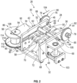
FIG. 2 illustrates a perspective view of an apparatus for decoupling an element that is bonded to a surface by adhesive in accordance with an exemplary embodiment; -
FIG. 3 illustrates a perspective side view of an apparatus that is coupled to an element that is bonded to a surface by adhesive in accordance with an exemplary embodiment; -
FIG. 4 illustrates another perspective side view of the apparatus depicted inFIG. 3 ; -
FIG. 5A illustrates a perspective view of an apparatus that is coupled to an element of a plurality of elements that are bonded to a surface by adhesive in accordance with an exemplary embodiment; -
FIG. 5B is a cross-sectional view of a portion of the apparatus disposed between one of the elements and the surface depicted inFIG. 5A alongline 5B-5B; -
FIG. 6 illustrates a perspective view of an apparatus for decoupling an element that is bonded to a surface by adhesive in accordance with an exemplary embodiment; and -
FIG. 7 illustrates a block diagram of a method for decoupling an element that is bonded to a surface by adhesive in accordance with an exemplary embodiment. - The following Detailed Description is merely exemplary in nature and is not intended to limit the various embodiments or the application and uses thereof. Furthermore, there is no intention to be bound by any theory presented in the preceding background or the following detailed description.
- Various embodiments contemplated herein relate to apparatuses and methods for decoupling an element that is bonded to a surface by adhesive. The exemplary embodiments taught herein provide an apparatus that includes a body, a spool that is rotationally coupled to the body, and a cable having a first cable end portion that is coupled to the spool, a second cable end portion that is coupled to the body, and a cable intermediate portion that is disposed between the first cable end portion and the second cable end portion. The apparatus is configured to be positioned adjacent to the element and/or the surface with the cable intermediate portion disposed adjacent to the adhesive such that when the spool is rotated, the cable wraps around the spool, thereby pulling the cable intermediate portion through the adhesive.
- In an exemplary embodiment, advantageously, by pulling the cable intermediate portion through the adhesive, the apparatus efficiently and effectively decouples the element from the surface without the need for labor-intensive efforts by workers. In one example, one worker operates the apparatus to pull the cable intermediate portion through the adhesive to decouple one or more elements from the surface while another worker collects the one or more decoupled element(s) as they fall or otherwise separate from the surface. As such, there is no need for the use of chemical solvents that can damage the element and/or the surface, and/or there is no need for the use of more labor-intensive manual processes that employ utility tools or the like that are ergonomically taxing on the workers.
-
FIG. 1 illustrates a perspective bottom view ofelements 10 that are bonded to asurface 12 by adhesive 14. In an exemplary embodiment, thesurface 12 is a vehicle surface, for example, an aircraft surface such as the underside of an aircraft wing, a portion of a fuselage, or the like. Theadhesive 14 may be in the form of an adhesive pad or layer and eachelement 10 may be bonded to thesurface 12 by a distinct or separate adhesive pad or layer. Alternatively, a plurality ofelements 10 may collectively be bonded to thesurface 12 by a single continuous adhesive layer. - As illustrated, the
elements 10 are made of metal and have a general T-shape extruded form. For example, each of theelements 10 includes aplate portion 16 that is bonded to thesurface 12 via theadhesive 14 and arib portion 18 that extends from theplate portion 16 in a direction generally away from thesurface 12. Therib portion 18 has anaperture 20 formed therethrough that allows for additional devices and/or constructions to be removably coupled to one or more of the element(s) 10. As illustrated, pairs ofmetal beams 22 are removably coupled to theelements 10 viafasteners 24 that extend through theapertures 20 and form awhiffletree construction 25. The whiffletree construction(s) 25 can be operatively coupled to a mechanical device(s) such as a jack(s) or hydraulic cylinder(s), for example, for distributing force substantially equally between theelements 10 for transfer through theadhesive 14 to thesurface 12 for aircraft performance testing. - Referring to
FIGS. 2 and5A , in an exemplary embodiment, themetal beams 22 illustrated inFIG. 1 are removed from theelements 10, for example, after aircraft performance testing has been completed. Anapparatus 26 for decoupling theelements 10 from thesurface 12 is disposed adj acent to thesurface 12 and, as will be discussed in further detail below, is removably coupled to one of theelements 10. - In an exemplary embodiment, the
apparatus 26 includes abody 28 that has abody side portion 30 and abody side portion 32 that is disposed opposite thebody side portion 30. Thebody side portions wall walls surfaces - The
apparatus 26 includes anattachment member 50 that includesspacers walls surfaces gap 55 therebetween. In an exemplary embodiment, thespacers spacers walls spacers holes attachment member 50 further includes ashaft 60 that is disposed in theholes surfaces shaft 60 is removably coupled to thebody 28 of theapparatus 26 by, for example,fasteners shaft 60, secure the shaft to thebody 28 and that when one or both of thefasteners shaft 60 to slide or otherwise move through theholes apparatus 26 may be attached or otherwise coupled to one of theelement 10, for example, by positioning theapparatus 26 with theshaft 60 fully or partially retracted (e.g., fully or partially outside of theholes 56 and 58) and therib portion 18 disposed between thegap 55 with theaperture 20 and theholes shaft 60 to extend through theaperture 20 and theholes shaft 60 to thebody 28 viafasteners - In an exemplary embodiment, each of the
surfaces walls track apparatus 26 includesspacers tracks spacers surfaces walls spacers gap 70 therebetween. Thespacers spacers gap 70 substantially aligned with thegap 55. As such, thegaps rib portion 18 of theelement 10 for attaching theapparatus 26 to one of theelements 10. In particular and without wishing to be bound by theory, it is believed that thespacers apparatus 26 when it is coupled to theelement 10 by providing elongated contact surfaces against opposite sides of therib portion 18 to limit rotational movement between theapparatus 26 and theelement 10 about theshaft 60 and secure the position of theapparatus 26 relative to thecorresponding element 10. - Referring also to
FIG. 4 , in an exemplary embodiment, theapparatus 26 includesbrackets body 28 of theapparatus 26. As illustrated, thebrackets walls body side portions - In an exemplary embodiment, the
apparatus 26 includespulleys upper pulley area lower pulley area annular track lower pulley areas cable 84 is disposed on thepulleys annular tracks spool 86 that is rotationally coupled to thebody 28 of theapparatus 26. As illustrated, thepulleys body side portions pulley 76 is coupled to thewall 34 and thesurface 42 faces towards thepulley 76. Similarly, thepulley 78 is coupled to thewall 36 with thesurface 44 facing towards thepulley 78. Thepulleys walls fasteners 88. In an exemplary embodiment, thepulleys - As will be discussed in further detail below, in accordance with an exemplary embodiment, the
spool 86 is rotationally coupled to thebody side portion 30 adjacent to thepulley 76 with thesurface 42 facing towards thespool 86. As illustrated, a bracket 90 (e.g., "U-shaped" bracket) is coupled to thebody side portion 30 and extends from thesurface 42 of thewall 34. Thespool 86 is disposed between flanges of thebracket 90 and is rotationally coupled to thebracket 90 by apin 94 that extends through the center of thespool 86 and is coupled to the flanges of thebracket 90. As such, thespool 86 is configured to rotate in directions (indicated by double headed arrow 96) about thepin 94. - In an exemplary embodiment, the
apparatus 26 includes aspool 103 that is coupled to thebody side portion 32. As illustrated, thespool 103 is disposed adjacent to thepulley 78 with thesurface 44 facing towards thespool 103. In an exemplary embodiment, thespool 103 is fixedly coupled to thebody side portion 32 to prevent rotation of thespool 103. For example, thespool 103 may be coupled to thewall 36 by a bracket 105 (e.g., "U-shaped" bracket) that is coupled to and extends from thesurface 44 of thewall 36. - With continuing reference to
FIGS. 2 and5A , thecable 84 has acable end portion 98 that is coupled to thespool 86, acable end portion 100 that is coupled to thebody side portion 32, and a cableintermediate portion 102 that is disposed therebetween. In an exemplary embodiment, thecable end portion 100 is coupled to thespool 103. In an exemplary embodiment, thepulleys intermediate portion 102 substantially level with the adhesive 14 when theapparatus 26 is coupled to theelement 10. The cableintermediate portion 102 extends from theupper pulley areas cable 84 is guided from theupper pulley areas lower pulley areas annular tracks cable 84 is guided from thelower pulley areas spools direction 104. - Referring also to
FIGS. 3 and4 , thespool 86 is configured to be rotated by adriver 106. In an exemplary embodiment, thespool 86 includesflanges drum 112 that is disposed between theflanges flange 110 includesteeth 114 disposed on the outer periphery thereof and is configured as agear 116. Although theflange 110 is illustrated as being configured as agear 116, various alternate embodiments of thespool 86 include theflange 110 as not being configured as a gear and aseparate gear 116 being coupled to thespool 86 either directly or indirectly to cause rotation of thedrum 112. In an exemplary embodiment, thecable end portion 98 is coupled to thedrum 112. - In an exemplary embodiment, the
apparatus 26 includes agear 118 that has a threaded portion that couples with thegear 116 and areceiver portion 120 that is configured to receive thedriver 106 to rotate thegear 118. As illustrated, thegear 116 is configured as a worm gear and thegear 118 is configured as a worm. As such, thegears driver 106 rotates thegear 118, the threaded portion of thegear 118 meshes with theteeth 114 of thegear 116, thereby rotating thegear 116 and, consequently, rotating thespool 86. - Referring also to
FIG. 5B , when theapparatus 26 is coupled to theelement 10 such that theapparatus 26 is positioned adjacent to thesurface 12 and the cableintermediate portion 102 is wrapped around the adhesive 14 and thedriver 106 rotates thespool 86, thecable 84 progressively wraps around thedrum 112, thereby pulling the cableintermediate portion 102 in a direction (indicated by single headed arrow 122) through the adhesive 14. In an exemplary embodiment, the adhesive 14 is thicker than the diameter of thecable 84 such that when thecable 84 is pulled through the adhesive 14, thecable 84 does not contact with thesurface 12 to further protect thesurface 12 from incurring any damage. Once the adhesive 14 has been cut by thecable 84, theelements 10 are fully decoupled from thesurface 12 and may fall or otherwise separate from thesurface 12. Any residual adhesive 14 that remains on thesurface 12 is now fully exposed and can be more readily accessed for easier removal by a worker(s) than with theelements 10 in place adhesively bonded to thesurface 12. - Referring to
FIG. 7 , amethod 200 for decoupling an element that is bonded to a surface by adhesive is provided. Themethod 200 includes positioning (STEP 202) an apparatus adjacent to at least one of the element and the surface. The apparatus includes a body, a spool that is rotationally coupled to the body, and a cable having a first cable end portion that is coupled to the first spool, a second cable end portion that is coupled to the body, and a cable intermediate portion that is disposed between the first cable end portion and the second cable end portion. The cable intermediate portion is disposed (STEP 204) adjacent to the adhesive. The spool is rotated (STEP 206) such that the cable wraps around the spool, thereby pulling the cable intermediate portion through the adhesive. - Referring to
FIG. 6 , another exemplary embodiment of theapparatus 124 is provided. Theapparatus 124 is similarly configured to theapparatus 26, but with the exception that thespool 86 is rotationally coupled to thebody side portion 32 viabracket 90 and thespool 103 is fixedly coupled to thebody side portion 30 viabracket 105. Further, spacers 146 and 148 depicted inFIG. 6 are wider than thespacers FIG. 2 . - While at least one exemplary embodiment has been presented in the foregoing detailed description of the disclosure, it should be appreciated that a vast number of variations exist. It should also be appreciated that the exemplary embodiment or exemplary embodiments are only examples, and are not intended to limit the scope, applicability, or configuration of the disclosure in any way. Rather, the foregoing detailed description will provide those skilled in the art with a convenient road map for implementing an exemplary embodiment of the disclosure. It being understood that various changes may be made in the function and arrangement of elements described in an exemplary embodiment without departing from the scope of the disclosure as set forth in the appended claims.
Claims (10)
- An apparatus (26) for decoupling an element (10) that is bonded to a surface (12) by adhesive (14), the apparatus (26) comprising:a body (28), wherein the body includes a first body side portion (30) and a second body side portion (32) that is disposed opposite the first body side portion (30);a first spool (86) that is rotationally coupled to the first body side portion (30);a second spool (103) that is coupled to the second body side portion (32);a first pulley (76) coupled to the first body side portion (30) adjacent to the first spool (86) and a second pulley (78) coupled to the second body side portion (32) adjacent to the second spool (103), wherein the first pulley (76) and the second pulley (78) are substantially aligned about a common axis; anda cable (84) having a first cable end portion (98) that is coupled to the first spool (86), a second cable end portion (100) that is coupled to the second spool (103), and a cable intermediate portion (102) that is disposed between the first cable end portion (98) and the second cable end portion (100),wherein the first pulley (76) guides the cable (84) to the first spool (86) as the first spool (86) rotates and the second pulley (78) guides the cable (84) to the second spool (103),wherein the apparatus (26) is configured to be positioned adjacent to at least one of the element (10) and the surface (12), andwherein the first (76) and second (78) pulleys are cooperatively configured to position the cable intermediate portion (102) adjacent to the adhesive (14) such that when the first spool (86) is rotated, the cable (84) wraps about the first spool (86), thereby pulling the cable intermediate portion (102) through the adhesive (14).
- The apparatus (26) of claim 1, wherein the apparatus (26) further includes a first gear (116) that is coupled to the first spool (86) to rotate the first spool (86) as the first gear (116) rotates.
- The apparatus (26) of claim 2, wherein the apparatus (26) further includes a second gear (118) that meshes with the first gear (116) to rotate the first gear (116).
- The apparatus (26) of claim 3, wherein the second gear (118) has a threaded portion that meshes with the first gear (116) and a receiver portion (120) that is configured to receive a driver (106) to rotate the second gear (118).
- The apparatus (26) of claim 4, wherein the first gear (116) and the second gear (118) are cooperatively configured as a worm drive.
- The apparatus (26) of claim 1, wherein the second spool (103) is fixedly coupled to the second body side portion (32) to prevent rotation of the second spool (103).
- The apparatus (26) of claim 1, wherein the cable intermediate portion (102) of the cable (84) extends from the first (76) and second (78) pulleys generally in a first direction to wrap at least partially around the adhesive (14).
- The apparatus (26) of claim 7, wherein the first body side (32) portion (30) includes a first wall (34) and the second body side portion (32) includes a second wall (36) that is spaced apart from the first wall (34).
- The apparatus (26) of any one of claims 1-8, wherein the apparatus (26) further includes an attachment member (50) that is coupled to the body (28) and that is configured to removably couple to at least one of the element (10) and the surface (12).
- A method for decoupling an element (10) that is bonded to a surface (12) by adhesive (14), the method comprising the steps of:positioning an apparatus (26) according to any one of claims 1-9 adjacent to at least one of the element (10) and the surface (12),disposing the cable intermediate portion (102) adjacent to the adhesive (14); androtating the first spool (86) such that the cable (84) wraps around the first spool (86), thereby pulling the cable intermediate portion (102) through the adhesive (14).
Applications Claiming Priority (1)
| Application Number | Priority Date | Filing Date | Title |
|---|---|---|---|
| US16/946,799 US11260647B2 (en) | 2020-07-07 | 2020-07-07 | Apparatus and method for decoupling an element that is bonded to a surface by adhesive |
Publications (2)
| Publication Number | Publication Date |
|---|---|
| EP3936290A1 EP3936290A1 (en) | 2022-01-12 |
| EP3936290B1 true EP3936290B1 (en) | 2024-12-04 |
Family
ID=76764875
Family Applications (1)
| Application Number | Title | Priority Date | Filing Date |
|---|---|---|---|
| EP21183385.0A Active EP3936290B1 (en) | 2020-07-07 | 2021-07-02 | Apparatus and method for decoupling an element that is bonded to a surface by adhesive |
Country Status (3)
| Country | Link |
|---|---|
| US (1) | US11260647B2 (en) |
| EP (1) | EP3936290B1 (en) |
| CN (1) | CN113915209A (en) |
Families Citing this family (1)
| Publication number | Priority date | Publication date | Assignee | Title |
|---|---|---|---|---|
| CN114800690A (en) * | 2022-04-27 | 2022-07-29 | 深圳市通泰盈科技股份有限公司 | Precise assembling and fitting equipment |
Family Cites Families (13)
| Publication number | Priority date | Publication date | Assignee | Title |
|---|---|---|---|---|
| US4003525A (en) * | 1975-07-14 | 1977-01-18 | Minnesota Mining And Manufacturing Company | Strip material unwinding device |
| US5144513A (en) * | 1989-06-21 | 1992-09-01 | Data Pure Corporation | Method and apparatus for cleaning magnetic tape having air bearings and vacuum-assisted cleaning |
| JP3256503B2 (en) * | 1998-11-05 | 2002-02-12 | 日本碍子株式会社 | Cutting equipment for ceramic green body products |
| US6832538B1 (en) * | 2000-01-06 | 2004-12-21 | Ber-Fong Hwang | Foam sponge cutting apparatus with both vertical and horizontal cutting devices |
| WO2004000511A2 (en) | 2002-06-21 | 2003-12-31 | Dow Global Technologies Inc. | Method and apparatus for adhesive joint separation |
| US8118075B2 (en) * | 2008-01-18 | 2012-02-21 | Rockwell Collins, Inc. | System and method for disassembling laminated substrates |
| US8349129B2 (en) * | 2008-04-11 | 2013-01-08 | Arizona Board Of Regents, A Body Corporate Of The State Of Arizona Acting For And On Behalf Of Arizona State University | Method and apparatus for debonding a submounted substrate |
| US20090283214A1 (en) | 2008-05-16 | 2009-11-19 | Jack Richard Nelson | Device and method for separating adhesive |
| TWI484454B (en) * | 2008-11-20 | 2015-05-11 | 杜邦股份有限公司 | Semi-automatic reworkability process for combining display |
| CA2830437C (en) * | 2011-03-17 | 2019-08-20 | Liquid Robotics, Inc. | Wave-powered devices configured for nesting |
| US10220537B2 (en) * | 2012-10-17 | 2019-03-05 | Saxum, Llc | Method and apparatus for display screen shield replacement |
| CN103676282A (en) * | 2013-12-23 | 2014-03-26 | 合肥京东方光电科技有限公司 | Touch screen and display screen separation device and method |
| IT201800009583A1 (en) | 2018-10-18 | 2020-04-18 | Giambattista Penna | EQUIPMENT FOR REMOVING THE WINDSCREEN OF A VEHICLE. |
-
2020
- 2020-07-07 US US16/946,799 patent/US11260647B2/en active Active
-
2021
- 2021-07-02 EP EP21183385.0A patent/EP3936290B1/en active Active
- 2021-07-06 CN CN202110760554.1A patent/CN113915209A/en active Pending
Also Published As
| Publication number | Publication date |
|---|---|
| EP3936290A1 (en) | 2022-01-12 |
| CN113915209A (en) | 2022-01-11 |
| US20220009218A1 (en) | 2022-01-13 |
| US11260647B2 (en) | 2022-03-01 |
Similar Documents
| Publication | Publication Date | Title |
|---|---|---|
| US10689104B2 (en) | Tail rotor integrated damper attachment | |
| US20240359043A1 (en) | Fall arrest system | |
| US11548129B2 (en) | Method and assembly for extracting press fit bushings | |
| US11260647B2 (en) | Apparatus and method for decoupling an element that is bonded to a surface by adhesive | |
| EP1912759B1 (en) | Method for connection at least two pieces of sheet material, particularly at least two metal sheets for a lightweight structure as well a joining and lightweight structure | |
| US11433987B2 (en) | Repair of over-frame blanket assemblies in aircraft | |
| DE3942918A1 (en) | AIRPLANE DRIVE SYSTEM WITH A PROPELLER RING AND A METHOD FOR REINFORCING SUCH A RING | |
| EP2751008B1 (en) | Escalator or moving walkway with a soffit plate | |
| EP3429880B1 (en) | Hybrid rim of a wheel with a wheel hub motor | |
| WO2018199032A1 (en) | Structure-frp material bond construction and bonding method | |
| EP0065086A1 (en) | Rotating member | |
| WO2015125838A1 (en) | Laminated panel | |
| DE102010013714B4 (en) | Method for fastening a cabin window, cabin windows and aircraft with such a cabin window | |
| EP0988964B1 (en) | Special adhesive laminate suitable for easy removal | |
| EP2660045B1 (en) | A laminated glazing with a member bonded thereto | |
| US20170050648A1 (en) | Mount assembly | |
| JP4416589B2 (en) | Reinforcing method for underground buried hollow structure and underground buried structure | |
| JP4040151B2 (en) | Reinforcing method for existing concrete structures | |
| GB2434348A (en) | Track-laying vehicle with cast track sub-frames | |
| CN222661696U (en) | Backpack type electric breaking and dismantling tool set | |
| WO2015126482A2 (en) | Field repair kits for structural panel | |
| US4548290A (en) | Road wheel mounting assembly | |
| DE102012002924A1 (en) | Carrier plate for torque transmission | |
| RU2412797C1 (en) | Installation for dismantling nuts of railway car half-shaft axle boxes (versions) | |
| CN120077002A (en) | Bearing replacement auxiliary tool for elevator traction machine and bearing replacement method |
Legal Events
| Date | Code | Title | Description |
|---|---|---|---|
| PUAI | Public reference made under article 153(3) epc to a published international application that has entered the european phase |
Free format text: ORIGINAL CODE: 0009012 |
|
| STAA | Information on the status of an ep patent application or granted ep patent |
Free format text: STATUS: REQUEST FOR EXAMINATION WAS MADE |
|
| 17P | Request for examination filed |
Effective date: 20210702 |
|
| AK | Designated contracting states |
Kind code of ref document: A1 Designated state(s): AL AT BE BG CH CY CZ DE DK EE ES FI FR GB GR HR HU IE IS IT LI LT LU LV MC MK MT NL NO PL PT RO RS SE SI SK SM TR |
|
| B565 | Issuance of search results under rule 164(2) epc |
Effective date: 20211201 |
|
| P01 | Opt-out of the competence of the unified patent court (upc) registered |
Effective date: 20230519 |
|
| GRAP | Despatch of communication of intention to grant a patent |
Free format text: ORIGINAL CODE: EPIDOSNIGR1 |
|
| STAA | Information on the status of an ep patent application or granted ep patent |
Free format text: STATUS: GRANT OF PATENT IS INTENDED |
|
| INTG | Intention to grant announced |
Effective date: 20240702 |
|
| GRAS | Grant fee paid |
Free format text: ORIGINAL CODE: EPIDOSNIGR3 |
|
| GRAA | (expected) grant |
Free format text: ORIGINAL CODE: 0009210 |
|
| STAA | Information on the status of an ep patent application or granted ep patent |
Free format text: STATUS: THE PATENT HAS BEEN GRANTED |
|
| AK | Designated contracting states |
Kind code of ref document: B1 Designated state(s): AL AT BE BG CH CY CZ DE DK EE ES FI FR GB GR HR HU IE IS IT LI LT LU LV MC MK MT NL NO PL PT RO RS SE SI SK SM TR |
|
| REG | Reference to a national code |
Ref country code: CH Ref legal event code: EP |
|
| REG | Reference to a national code |
Ref country code: DE Ref legal event code: R096 Ref document number: 602021022720 Country of ref document: DE |
|
| REG | Reference to a national code |
Ref country code: IE Ref legal event code: FG4D |
|
| REG | Reference to a national code |
Ref country code: LT Ref legal event code: MG9D |
|
| REG | Reference to a national code |
Ref country code: NL Ref legal event code: MP Effective date: 20241204 |
|
| PG25 | Lapsed in a contracting state [announced via postgrant information from national office to epo] |
Ref country code: HR Free format text: LAPSE BECAUSE OF FAILURE TO SUBMIT A TRANSLATION OF THE DESCRIPTION OR TO PAY THE FEE WITHIN THE PRESCRIBED TIME-LIMIT Effective date: 20241204 |
|
| PG25 | Lapsed in a contracting state [announced via postgrant information from national office to epo] |
Ref country code: FI Free format text: LAPSE BECAUSE OF FAILURE TO SUBMIT A TRANSLATION OF THE DESCRIPTION OR TO PAY THE FEE WITHIN THE PRESCRIBED TIME-LIMIT Effective date: 20241204 |
|
| PG25 | Lapsed in a contracting state [announced via postgrant information from national office to epo] |
Ref country code: BG Free format text: LAPSE BECAUSE OF FAILURE TO SUBMIT A TRANSLATION OF THE DESCRIPTION OR TO PAY THE FEE WITHIN THE PRESCRIBED TIME-LIMIT Effective date: 20241204 |
|
| PG25 | Lapsed in a contracting state [announced via postgrant information from national office to epo] |
Ref country code: ES Free format text: LAPSE BECAUSE OF FAILURE TO SUBMIT A TRANSLATION OF THE DESCRIPTION OR TO PAY THE FEE WITHIN THE PRESCRIBED TIME-LIMIT Effective date: 20241204 |
|
| PG25 | Lapsed in a contracting state [announced via postgrant information from national office to epo] |
Ref country code: NO Free format text: LAPSE BECAUSE OF FAILURE TO SUBMIT A TRANSLATION OF THE DESCRIPTION OR TO PAY THE FEE WITHIN THE PRESCRIBED TIME-LIMIT Effective date: 20250304 |
|
| PG25 | Lapsed in a contracting state [announced via postgrant information from national office to epo] |
Ref country code: LV Free format text: LAPSE BECAUSE OF FAILURE TO SUBMIT A TRANSLATION OF THE DESCRIPTION OR TO PAY THE FEE WITHIN THE PRESCRIBED TIME-LIMIT Effective date: 20241204 Ref country code: GR Free format text: LAPSE BECAUSE OF FAILURE TO SUBMIT A TRANSLATION OF THE DESCRIPTION OR TO PAY THE FEE WITHIN THE PRESCRIBED TIME-LIMIT Effective date: 20250305 |
|
| PG25 | Lapsed in a contracting state [announced via postgrant information from national office to epo] |
Ref country code: RS Free format text: LAPSE BECAUSE OF FAILURE TO SUBMIT A TRANSLATION OF THE DESCRIPTION OR TO PAY THE FEE WITHIN THE PRESCRIBED TIME-LIMIT Effective date: 20250304 |
|
| PG25 | Lapsed in a contracting state [announced via postgrant information from national office to epo] |
Ref country code: NL Free format text: LAPSE BECAUSE OF FAILURE TO SUBMIT A TRANSLATION OF THE DESCRIPTION OR TO PAY THE FEE WITHIN THE PRESCRIBED TIME-LIMIT Effective date: 20241204 |
|
| REG | Reference to a national code |
Ref country code: AT Ref legal event code: MK05 Ref document number: 1747679 Country of ref document: AT Kind code of ref document: T Effective date: 20241204 |
|
| PG25 | Lapsed in a contracting state [announced via postgrant information from national office to epo] |
Ref country code: SM Free format text: LAPSE BECAUSE OF FAILURE TO SUBMIT A TRANSLATION OF THE DESCRIPTION OR TO PAY THE FEE WITHIN THE PRESCRIBED TIME-LIMIT Effective date: 20241204 |
|
| PG25 | Lapsed in a contracting state [announced via postgrant information from national office to epo] |
Ref country code: PL Free format text: LAPSE BECAUSE OF FAILURE TO SUBMIT A TRANSLATION OF THE DESCRIPTION OR TO PAY THE FEE WITHIN THE PRESCRIBED TIME-LIMIT Effective date: 20241204 |
|
| PG25 | Lapsed in a contracting state [announced via postgrant information from national office to epo] |
Ref country code: IS Free format text: LAPSE BECAUSE OF FAILURE TO SUBMIT A TRANSLATION OF THE DESCRIPTION OR TO PAY THE FEE WITHIN THE PRESCRIBED TIME-LIMIT Effective date: 20250404 |
|
| PG25 | Lapsed in a contracting state [announced via postgrant information from national office to epo] |
Ref country code: PT Free format text: LAPSE BECAUSE OF FAILURE TO SUBMIT A TRANSLATION OF THE DESCRIPTION OR TO PAY THE FEE WITHIN THE PRESCRIBED TIME-LIMIT Effective date: 20250404 |
|
| PG25 | Lapsed in a contracting state [announced via postgrant information from national office to epo] |
Ref country code: EE Free format text: LAPSE BECAUSE OF FAILURE TO SUBMIT A TRANSLATION OF THE DESCRIPTION OR TO PAY THE FEE WITHIN THE PRESCRIBED TIME-LIMIT Effective date: 20241204 |
|
| PG25 | Lapsed in a contracting state [announced via postgrant information from national office to epo] |
Ref country code: AT Free format text: LAPSE BECAUSE OF FAILURE TO SUBMIT A TRANSLATION OF THE DESCRIPTION OR TO PAY THE FEE WITHIN THE PRESCRIBED TIME-LIMIT Effective date: 20241204 Ref country code: RO Free format text: LAPSE BECAUSE OF FAILURE TO SUBMIT A TRANSLATION OF THE DESCRIPTION OR TO PAY THE FEE WITHIN THE PRESCRIBED TIME-LIMIT Effective date: 20241204 |
|
| PG25 | Lapsed in a contracting state [announced via postgrant information from national office to epo] |
Ref country code: SK Free format text: LAPSE BECAUSE OF FAILURE TO SUBMIT A TRANSLATION OF THE DESCRIPTION OR TO PAY THE FEE WITHIN THE PRESCRIBED TIME-LIMIT Effective date: 20241204 |
|
| PG25 | Lapsed in a contracting state [announced via postgrant information from national office to epo] |
Ref country code: CZ Free format text: LAPSE BECAUSE OF FAILURE TO SUBMIT A TRANSLATION OF THE DESCRIPTION OR TO PAY THE FEE WITHIN THE PRESCRIBED TIME-LIMIT Effective date: 20241204 |
|
| PG25 | Lapsed in a contracting state [announced via postgrant information from national office to epo] |
Ref country code: IT Free format text: LAPSE BECAUSE OF FAILURE TO SUBMIT A TRANSLATION OF THE DESCRIPTION OR TO PAY THE FEE WITHIN THE PRESCRIBED TIME-LIMIT Effective date: 20241204 |
|
| REG | Reference to a national code |
Ref country code: DE Ref legal event code: R097 Ref document number: 602021022720 Country of ref document: DE |
|
| PG25 | Lapsed in a contracting state [announced via postgrant information from national office to epo] |
Ref country code: SE Free format text: LAPSE BECAUSE OF FAILURE TO SUBMIT A TRANSLATION OF THE DESCRIPTION OR TO PAY THE FEE WITHIN THE PRESCRIBED TIME-LIMIT Effective date: 20241204 |
|
| PG25 | Lapsed in a contracting state [announced via postgrant information from national office to epo] |
Ref country code: DK Free format text: LAPSE BECAUSE OF FAILURE TO SUBMIT A TRANSLATION OF THE DESCRIPTION OR TO PAY THE FEE WITHIN THE PRESCRIBED TIME-LIMIT Effective date: 20241204 |
|
| PGFP | Annual fee paid to national office [announced via postgrant information from national office to epo] |
Ref country code: DE Payment date: 20250530 Year of fee payment: 5 |
|
| PLBE | No opposition filed within time limit |
Free format text: ORIGINAL CODE: 0009261 |
|
| STAA | Information on the status of an ep patent application or granted ep patent |
Free format text: STATUS: NO OPPOSITION FILED WITHIN TIME LIMIT |
|
| REG | Reference to a national code |
Ref country code: CH Ref legal event code: L10 Free format text: ST27 STATUS EVENT CODE: U-0-0-L10-L00 (AS PROVIDED BY THE NATIONAL OFFICE) Effective date: 20251015 |
|
| 26N | No opposition filed |
Effective date: 20250905 |
|
| REG | Reference to a national code |
Ref country code: CH Ref legal event code: H13 Free format text: ST27 STATUS EVENT CODE: U-0-0-H10-H13 (AS PROVIDED BY THE NATIONAL OFFICE) Effective date: 20260224 |
|
| PG25 | Lapsed in a contracting state [announced via postgrant information from national office to epo] |
Ref country code: LU Free format text: LAPSE BECAUSE OF NON-PAYMENT OF DUE FEES Effective date: 20250702 |
|
| GBPC | Gb: european patent ceased through non-payment of renewal fee |
Effective date: 20250702 |
|
| REG | Reference to a national code |
Ref country code: BE Ref legal event code: MM Effective date: 20250731 |
|
| PG25 | Lapsed in a contracting state [announced via postgrant information from national office to epo] |
Ref country code: GB Free format text: LAPSE BECAUSE OF NON-PAYMENT OF DUE FEES Effective date: 20250702 |
|
| PG25 | Lapsed in a contracting state [announced via postgrant information from national office to epo] |
Ref country code: BE Free format text: LAPSE BECAUSE OF NON-PAYMENT OF DUE FEES Effective date: 20250731 |
|
| PG25 | Lapsed in a contracting state [announced via postgrant information from national office to epo] |
Ref country code: FR Free format text: LAPSE BECAUSE OF NON-PAYMENT OF DUE FEES Effective date: 20250731 |
|
| PG25 | Lapsed in a contracting state [announced via postgrant information from national office to epo] |
Ref country code: CH Free format text: LAPSE BECAUSE OF NON-PAYMENT OF DUE FEES Effective date: 20250731 |