EP3936218A1 - Monolithic swing bed adsorption apparatus - Google Patents
Monolithic swing bed adsorption apparatus Download PDFInfo
- Publication number
- EP3936218A1 EP3936218A1 EP21184506.0A EP21184506A EP3936218A1 EP 3936218 A1 EP3936218 A1 EP 3936218A1 EP 21184506 A EP21184506 A EP 21184506A EP 3936218 A1 EP3936218 A1 EP 3936218A1
- Authority
- EP
- European Patent Office
- Prior art keywords
- bed
- additive manufacturing
- monolithic
- manufacturing technique
- forming
- Prior art date
- Legal status (The legal status is an assumption and is not a legal conclusion. Google has not performed a legal analysis and makes no representation as to the accuracy of the status listed.)
- Pending
Links
Images


Classifications
-
- B—PERFORMING OPERATIONS; TRANSPORTING
- B01—PHYSICAL OR CHEMICAL PROCESSES OR APPARATUS IN GENERAL
- B01D—SEPARATION
- B01D53/00—Separation of gases or vapours; Recovering vapours of volatile solvents from gases; Chemical or biological purification of waste gases, e.g. engine exhaust gases, smoke, fumes, flue gases, aerosols
- B01D53/02—Separation of gases or vapours; Recovering vapours of volatile solvents from gases; Chemical or biological purification of waste gases, e.g. engine exhaust gases, smoke, fumes, flue gases, aerosols by adsorption, e.g. preparative gas chromatography
- B01D53/04—Separation of gases or vapours; Recovering vapours of volatile solvents from gases; Chemical or biological purification of waste gases, e.g. engine exhaust gases, smoke, fumes, flue gases, aerosols by adsorption, e.g. preparative gas chromatography with stationary adsorbents
- B01D53/0407—Constructional details of adsorbing systems
-
- B—PERFORMING OPERATIONS; TRANSPORTING
- B01—PHYSICAL OR CHEMICAL PROCESSES OR APPARATUS IN GENERAL
- B01D—SEPARATION
- B01D53/00—Separation of gases or vapours; Recovering vapours of volatile solvents from gases; Chemical or biological purification of waste gases, e.g. engine exhaust gases, smoke, fumes, flue gases, aerosols
- B01D53/34—Chemical or biological purification of waste gases
- B01D53/74—General processes for purification of waste gases; Apparatus or devices specially adapted therefor
- B01D53/81—Solid phase processes
- B01D53/82—Solid phase processes with stationary reactants
-
- A—HUMAN NECESSITIES
- A62—LIFE-SAVING; FIRE-FIGHTING
- A62B—DEVICES, APPARATUS OR METHODS FOR LIFE-SAVING
- A62B11/00—Devices for reconditioning breathing air in sealed rooms
-
- B—PERFORMING OPERATIONS; TRANSPORTING
- B01—PHYSICAL OR CHEMICAL PROCESSES OR APPARATUS IN GENERAL
- B01D—SEPARATION
- B01D53/00—Separation of gases or vapours; Recovering vapours of volatile solvents from gases; Chemical or biological purification of waste gases, e.g. engine exhaust gases, smoke, fumes, flue gases, aerosols
- B01D53/02—Separation of gases or vapours; Recovering vapours of volatile solvents from gases; Chemical or biological purification of waste gases, e.g. engine exhaust gases, smoke, fumes, flue gases, aerosols by adsorption, e.g. preparative gas chromatography
- B01D53/04—Separation of gases or vapours; Recovering vapours of volatile solvents from gases; Chemical or biological purification of waste gases, e.g. engine exhaust gases, smoke, fumes, flue gases, aerosols by adsorption, e.g. preparative gas chromatography with stationary adsorbents
- B01D53/0407—Constructional details of adsorbing systems
- B01D53/0446—Means for feeding or distributing gases
-
- B—PERFORMING OPERATIONS; TRANSPORTING
- B01—PHYSICAL OR CHEMICAL PROCESSES OR APPARATUS IN GENERAL
- B01D—SEPARATION
- B01D53/00—Separation of gases or vapours; Recovering vapours of volatile solvents from gases; Chemical or biological purification of waste gases, e.g. engine exhaust gases, smoke, fumes, flue gases, aerosols
- B01D53/34—Chemical or biological purification of waste gases
- B01D53/46—Removing components of defined structure
- B01D53/62—Carbon oxides
-
- B—PERFORMING OPERATIONS; TRANSPORTING
- B01—PHYSICAL OR CHEMICAL PROCESSES OR APPARATUS IN GENERAL
- B01J—CHEMICAL OR PHYSICAL PROCESSES, e.g. CATALYSIS OR COLLOID CHEMISTRY; THEIR RELEVANT APPARATUS
- B01J20/00—Solid sorbent compositions or filter aid compositions; Sorbents for chromatography; Processes for preparing, regenerating or reactivating thereof
- B01J20/22—Solid sorbent compositions or filter aid compositions; Sorbents for chromatography; Processes for preparing, regenerating or reactivating thereof comprising organic material
-
- B—PERFORMING OPERATIONS; TRANSPORTING
- B01—PHYSICAL OR CHEMICAL PROCESSES OR APPARATUS IN GENERAL
- B01J—CHEMICAL OR PHYSICAL PROCESSES, e.g. CATALYSIS OR COLLOID CHEMISTRY; THEIR RELEVANT APPARATUS
- B01J20/00—Solid sorbent compositions or filter aid compositions; Sorbents for chromatography; Processes for preparing, regenerating or reactivating thereof
- B01J20/28—Solid sorbent compositions or filter aid compositions; Sorbents for chromatography; Processes for preparing, regenerating or reactivating thereof characterised by their form or physical properties
- B01J20/28014—Solid sorbent compositions or filter aid compositions; Sorbents for chromatography; Processes for preparing, regenerating or reactivating thereof characterised by their form or physical properties characterised by their form
- B01J20/28042—Shaped bodies; Monolithic structures
-
- B—PERFORMING OPERATIONS; TRANSPORTING
- B01—PHYSICAL OR CHEMICAL PROCESSES OR APPARATUS IN GENERAL
- B01J—CHEMICAL OR PHYSICAL PROCESSES, e.g. CATALYSIS OR COLLOID CHEMISTRY; THEIR RELEVANT APPARATUS
- B01J20/00—Solid sorbent compositions or filter aid compositions; Sorbents for chromatography; Processes for preparing, regenerating or reactivating thereof
- B01J20/30—Processes for preparing, regenerating, or reactivating
- B01J20/3007—Moulding, shaping or extruding
-
- B—PERFORMING OPERATIONS; TRANSPORTING
- B33—ADDITIVE MANUFACTURING TECHNOLOGY
- B33Y—ADDITIVE MANUFACTURING, i.e. MANUFACTURING OF THREE-DIMENSIONAL [3D] OBJECTS BY ADDITIVE DEPOSITION, ADDITIVE AGGLOMERATION OR ADDITIVE LAYERING, e.g. BY 3D PRINTING, STEREOLITHOGRAPHY OR SELECTIVE LASER SINTERING
- B33Y10/00—Processes of additive manufacturing
-
- B—PERFORMING OPERATIONS; TRANSPORTING
- B33—ADDITIVE MANUFACTURING TECHNOLOGY
- B33Y—ADDITIVE MANUFACTURING, i.e. MANUFACTURING OF THREE-DIMENSIONAL [3D] OBJECTS BY ADDITIVE DEPOSITION, ADDITIVE AGGLOMERATION OR ADDITIVE LAYERING, e.g. BY 3D PRINTING, STEREOLITHOGRAPHY OR SELECTIVE LASER SINTERING
- B33Y80/00—Products made by additive manufacturing
-
- B—PERFORMING OPERATIONS; TRANSPORTING
- B01—PHYSICAL OR CHEMICAL PROCESSES OR APPARATUS IN GENERAL
- B01D—SEPARATION
- B01D2251/00—Reactants
- B01D2251/60—Inorganic bases or salts
-
- B—PERFORMING OPERATIONS; TRANSPORTING
- B01—PHYSICAL OR CHEMICAL PROCESSES OR APPARATUS IN GENERAL
- B01D—SEPARATION
- B01D2253/00—Adsorbents used in seperation treatment of gases and vapours
- B01D2253/30—Physical properties of adsorbents
- B01D2253/34—Specific shapes
- B01D2253/342—Monoliths
-
- B—PERFORMING OPERATIONS; TRANSPORTING
- B01—PHYSICAL OR CHEMICAL PROCESSES OR APPARATUS IN GENERAL
- B01D—SEPARATION
- B01D2257/00—Components to be removed
- B01D2257/50—Carbon oxides
- B01D2257/504—Carbon dioxide
-
- B—PERFORMING OPERATIONS; TRANSPORTING
- B01—PHYSICAL OR CHEMICAL PROCESSES OR APPARATUS IN GENERAL
- B01D—SEPARATION
- B01D2259/00—Type of treatment
- B01D2259/45—Gas separation or purification devices adapted for specific applications
- B01D2259/4566—Gas separation or purification devices adapted for specific applications for use in transportation means
- B01D2259/4575—Gas separation or purification devices adapted for specific applications for use in transportation means in aeroplanes or space ships
-
- Y—GENERAL TAGGING OF NEW TECHNOLOGICAL DEVELOPMENTS; GENERAL TAGGING OF CROSS-SECTIONAL TECHNOLOGIES SPANNING OVER SEVERAL SECTIONS OF THE IPC; TECHNICAL SUBJECTS COVERED BY FORMER USPC CROSS-REFERENCE ART COLLECTIONS [XRACs] AND DIGESTS
- Y02—TECHNOLOGIES OR APPLICATIONS FOR MITIGATION OR ADAPTATION AGAINST CLIMATE CHANGE
- Y02C—CAPTURE, STORAGE, SEQUESTRATION OR DISPOSAL OF GREENHOUSE GASES [GHG]
- Y02C20/00—Capture or disposal of greenhouse gases
- Y02C20/40—Capture or disposal of greenhouse gases of CO2
Definitions
- the subject matter disclosed herein relates generally to the field of removing carbon dioxide gas, and specifically to an apparatus for absorbing and removing carbon dioxide gas from an enclosed space.
- a regenerative carbon dioxide removal system is utilized for this purpose and commonly includes amine beds that are placed in contact with a flow of carbon dioxide laden air. The amine beds adsorb carbon dioxide from the air stream through commonly understood chemical processes and reactions.
- An amine bed is utilized until it is saturated to a selected saturation level.
- the selected saturation level can be a saturation level where the amine bed can no longer efficiently remove carbon dioxide from an air stream or any saturation level less than the saturation level where the amine bed can no longer efficiently remove carbon dioxide from the air stream.
- Another amine bed is then switched into contact with the carbon dioxide laden air stream. The saturated amine bed is then desorbed to expel carbon dioxide in preparation for the next cycle.
- a monolithic swing bed absorption apparatus including a first bed.
- the first bed including a bed housing including a first side and a second side, a first manifold section extending from the first side to the second side within the bed housing, a filtration section extending from the first side to the second side within the bed housing, and a second manifold section extending from the first side to the second side within the bed housing.
- the filtration section being interposed between the first manifold section and the second manifold section.
- the monolithic swing bed absorption apparatus is a single piece including a unitary structure.
- further embodiments may include that the monolithic swing bed absorption apparatus is a monolithic structure formed via an additive manufacturing technique.
- further embodiments may include that the additive manufacturing technique is powder bed fusion additive manufacturing.
- first bed further includes a first screen portion interposed between the first manifold section and the filtration section, and a second screen portion interposed between the filtration section and the second manifold section.
- further embodiments may include that the first manifold section, the filtration section, and the second manifold section have an engineered open cell structural geometry configured to increase flow and filtration.
- further embodiments may include that the open cell structural geometry is a Kelvin cell geometry.
- the bed housing further includes a first opening in the first side of the bed housing.
- the first opening in the first side being aligned with the first manifold section.
- the bed housing further includes a second opening in the first side of the bed housing.
- the second opening in the first side being aligned with the filtration section.
- the bed housing further includes a first opening in the second side of the bed housing. The first opening in the second side being aligned with the second manifold section.
- further embodiments may include a first end portion.
- further embodiments may include a second bed and a parting sheet interposed between the first bed and the second bed.
- further embodiments may include a first end portion, a second bed, a third bed, a fourth bed, and a second end portion located opposite the first end portion.
- a method of manufacturing a monolithic swing bed absorption apparatus including: forming a first bed, including: forming, using an additive manufacturing technique, a bed housing including a first side and a second side; forming, using the additive manufacturing technique, a first manifold section extending from the first side to the second side within the bed housing; forming, using the additive manufacturing technique, a filtration section extending from the first side to the second side within the bed housing; and forming, using the additive manufacturing technique, a second manifold section extending from the first side to the second side within the bed housing, the filtration section being interposed between the first manifold section and the second manifold section.
- the monolithic swing bed absorption apparatus is a single piece including a unitary structure.
- further embodiments may include that the additive manufacturing technique is powder bed fusion additive manufacturing.
- further embodiments may include that the monolithic swing bed absorption apparatus is a monolithic structure formed by the additive manufacturing technique.
- further embodiments may include that the forming the first bed further includes: forming, using the additive manufacturing technique, a first screen portion interposed between the first manifold section and the filtration section; and forming, using the additive manufacturing technique, a second screen portion interposed between the filtration section and the second manifold section.
- further embodiments may include that the first manifold section, the filtration section, and the second manifold section have an engineered open cell structural geometry configured to increase flow and filtration.
- further embodiments may include that the open cell structural geometry is a Kelvin cell geometry.
- further embodiments may include that the forming the first bed further includes: forming, using the additive manufacturing technique, a first opening in the first side of the bed housing, the first opening in the first side being aligned with the first manifold section; forming, using the additive manufacturing technique, a second opening in the first side of the bed housing, the second opening in the first side being aligned with the filtration section; and forming, using the additive manufacturing technique, a first opening in the second side of the bed housing, the first opening in the second side being aligned with the second manifold section.
- further embodiments may include forming, using the additive manufacturing technique, a first end portion.
- further embodiments may include forming, using the additive manufacturing technique, a second bed; and forming, using the additive manufacturing technique, a parting sheet interposed between the first bed and the second bed.
- further embodiments may include forming, using the additive manufacturing technique, a first end portion; forming, using the additive manufacturing technique, a second bed; forming, using the additive manufacturing technique, a third bed; forming, using the additive manufacturing technique, a fourth bed; and forming, using the additive manufacturing technique, a second end portion located opposite the first end portion.
- a multi-piece swing bed absorption apparatus for the amine beds are typically constructed utilizing a complex arrangement of a multitude of brazed amine support features, filters, and screens.
- the assembly process is complex and time consuming due to the multitude of parts involved.
- the brazing process is a process that requires the entire housing to be exposed to a temperature sufficient to form the desired brazed joints and leaves being visible joints and seams.
- Embodiments disclosed herein seek to simplify the assembly process by reducing the number of components and eliminating brazing entirely and eliminating any joints on the structure that are left over from brazing.
- the monolithic swing bed absorption apparatus 200 is a monolithic structure formed via an additive manufacturing technique.
- the monolithic swing bed absorption apparatus 200 is a monolithic structure rather than being assembled from separate individually formed components that are then assembled, as in previous designs.
- the term monolithic may be defined as an object that is cast or formed as single piece without joints or seams.
- the monolithic swing bed structure 200 is formed as a single piece comprising a unitary structure.
- the monolithic swing bed absorption apparatus 200 has no joints or seams.
- the monolithic swing bed absorption apparatus 200 may be manufactured or formed via an additive manufacturing technique known to one of skill in the art. In an embodiment, the monolithic swing bed absorption apparatus 200 may be manufactured by growing the structure all at once or one layer at a time. In an embodiment, the monolithic swing bed absorption apparatus 200 may be manufactured by powder bed fusion additive manufacturing.
- the monolithic swing bed absorption apparatus 200 by manufacturing the monolithic swing bed absorption apparatus 200 as a monolithic structure using additive manufacturing it eliminates the manufacturing and/or procurement of all the separate components in the multi-piece assembly, which saves cost and time. Also advantageously, by manufacturing the monolithic swing bed absorption apparatus 200 as a monolithic structure using additive manufacturing it eliminates the need to braze all of the separate components of a multi-piece swing bed absorption apparatus, which saves cost and time. Also advantageously, by avoiding the need to braze any components together, different materials may be utilized for the monolithic structure that would have not be utilized previously due to the excess heat involved in brazing. Additionally, the potential for leaks or leak paths from numerous brazed joints is eliminated and thus an all-around more robust design is created.
- the monolithic swing bed absorption apparatus 200 is composed of two or more beds 240.
- the two or more beds 240 are formed stacked on top of each other.
- the beds 240 may be formed one bed 240 at a time, such as, for example, starting from the second end portion 220 and moving to the first end portion 210, or starting from the first end portion 210 and moving to the second end portion 220.
- the monolithic swing bed absorption apparatus 200 of FIG. 1 includes four beds 240.
- the beds 240 are sandwiched together by a first end portion 210 (i.e., bottom end portion according to the illustrated orientation) and a second end portion 220 (i.e., a top end portion according to the illustrated orientation).
- the first end portion 210 is located at a first end 202 of the monolithic swing bed absorption apparatus 200 and the second end portion 220 is located at a second end 204 of the monolithic swing bed absorption apparatus 200.
- the monolithic swing bed absorption apparatus 200 is composed of two or more beds 240.
- Each of the beds 240 is composed of a bed housing 242, a first manifold section 250, a first screen portion 260, a filtration section 270, a second screen portion 280, a second manifold section 290, and a parting sheet 230.
- the filtration section 270 contains amine-based sorbent beads to absorb carbon dioxide.
- the exemplary monolithic swing bed absorption apparatus 200 of FIG. 2 includes four beds 240, the embodiments disclosed herein may be applicable to a monolithic swing bed absorption apparatus 200 with two or more beds 240.
- the beds 240 include a first bed 240a, a second bed 240b, a third bed 240c, and a fourth bed 240d.
- the parting sheet 230 separates two adjacent beds 240.
- a parting sheet 230 is also interposed between the first bed 240a and the second bed 240b, the second bed 240b and the third bed 240c, the third bed 240c and the fourth bed 240d.
- the filtration section 270 is interposed between the first manifold section 250 and the second manifold section 290.
- the first screen portion 260 is interposed between the first manifold section 250 and the filtration section 270.
- the second screen portion 280 is interposed between the filtration section 270 and the second manifold section 290.
- the first screen portion 260 is produced via additive manufacturing there is no need for a screen frame.
- Previously designs that were produced via brazing techniques required a separate screen and a separate screen frame be assembled together. The screen frame would provide structural support to the screen, which is no longer necessary in the present design.
- the second screen portion 280 is produced via additive manufacturing there is no need for a screen frame.
- first manifold section 250, the filtration section 270, and the second manifold section 290 are no longer limited to a foam or foam-like material, as in previous designs.
- the first manifold section 250, the filtration section 270, and the second manifold section 290 may be shaped by the additive manufacturing technique to have an engineered open cell structural geometry configured to increase flow and filtration over previous designs.
- the engineered open cell structural geometry performs flow optimization and filtration.
- the open cell structural geometries may include but are not limited to a Kelvin cell geometry.
- the first manifold section 250 may have the same engineered open cell structural geometry as the second manifold section 290.
- the bed housing 242 includes a first opening 245 in a first side 243 of the bed housing 242 and a second opening 247 in the first side 243 of the bed housing 242.
- the first opening 245 is aligned with the first manifold section 250 and the second opening 247 is aligned with the filtration section 270.
- the bed housing 242 includes a first opening 246 in a second side 244 of the bed housing 242 and a second opening 248 in the second side 244 of the bed housing 242.
- the first opening 246 is aligned with the second manifold section 290 and the second opening 248 is aligned with the filtration section 270.
- the second opening 248 may not be present.
- Air 208 to be filtered is configured to flow into the monolithic swing bed absorption apparatus 200 through the first opening 245 in the first side 243 of the bed housing 242, through the first manifold section 250, then through the first screen portion 260, then through the filtration section 270, then through the second screen portion 280, then through the second manifold section 290 and then through a first opening 246 in the second side 244 of the bed housing 242 to exit the monolithic swing bed absorption apparatus 200.
- the filtration section 270 is desorbed to expel carbon dioxide in preparation for the next cycle by exposing the bed to a vacuum.
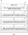
- FIG. 3 a flow chart of method 600 of manufacturing the monolithic swing bed absorption apparatus 200 is illustrated, in accordance with an embodiment of the disclosure.
- a first bed 240a is formed comprising the steps of blocks 604, 606, 608, and 610.
- blocks 604, 606, 608, and 610 may occur simultaneously or near simultaneously as each of the bed housing 242, the first manifold section 250, the filtration section 270, and the second manifold section 290 are built up in layers.
- a bed housing 242 comprising a first side 243 and a second side 244 is formed using an additive manufacturing technique.
- a first manifold section 250 extending from the first side 243 to the second side 244 is formed within the bed housing 242 using the additive manufacturing technique.
- a filtration section 270 extending from the first side 243 to the second side 244 is formed within the bed housing 242 using the additive manufacturing technique.
- a second manifold section 290 extending from the first side 243 to the second side 244 is formed within the bed housing 242 using the additive manufacturing technique. The filtration section 270 being interposed between the first manifold section 250 and the second manifold section 290.
- the monolithic swing bed absorption apparatus 200 is a single piece comprising a unitary structure.
- the monolithic swing bed absorption apparatus 200 is a monolithic structure formed by the additive manufacturing technique.
- the additive manufacturing technique is powder bed fusion additive manufacturing.
- the method 600 may further comprise that a first screen portion 260 is formed interposed between the first manifold section 250 and the filtration section 270 using the additive manufacturing technique.
- the method 600 may further comprise that a second screen portion 280 is formed interposed between the filtration section 270 and the second manifold section 290 using the additive manufacturing technique.
- the first manifold section 250, the filtration section 270, and the second manifold section 290 have an engineered open cell structural geometry configured to perform filtration.
- the open cell structural geometry is a Kelvin cell geometry. In is understood that the embodiments disclosed herein are applicable to geometries other than the Kelvin cell geometry.
- the method 600 may further comprise that a first opening 245 is formed in the first side 243 of the bed housing 242 using the additive manufacturing technique.
- the first opening 245 in the first side 243 being aligned with the first manifold section 250.
- the method 600 may further comprise that a second opening 247 is formed in the first side 243 of the bed housing 242 using the additive manufacturing technique.
- the second opening 247 in the first side 243 being aligned with the filtration section 270.
- the method 600 may further comprise that a first opening 246 is formed in the second side 244 of the bed housing 242 using the additive manufacturing technique.
- the first opening 246 in the second side 244 being aligned with the second manifold section 290.
- the method 600 may further comprise that a second opening 248 is formed in the second side 244 of the bed housing 242 using the additive manufacturing technique.
- the second opening 248 in the second side 244 being aligned with the filtration section 270.
- the second opening 248 may not be present.
- the method 600 may further comprise that a first end portion 210 is formed using the additive manufacturing technique.
- the method 600 may further comprise that a second bed 240b is formed using the additive manufacturing technique and a parting sheet 230 interposed between the first bed 240a and the second bed 240b is formed using the additive manufacturing technique.
- the method 600 may additionally comprise that a first end portion 210, a second bed 240b, a third bed 240c, a fourth bed 240d, and a second end portion 220 located opposite the first end portion 210 are each formed using the additive manufacturing technique.
Landscapes
- Chemical & Material Sciences (AREA)
- Engineering & Computer Science (AREA)
- Chemical Kinetics & Catalysis (AREA)
- Analytical Chemistry (AREA)
- Health & Medical Sciences (AREA)
- Oil, Petroleum & Natural Gas (AREA)
- General Chemical & Material Sciences (AREA)
- Organic Chemistry (AREA)
- Environmental & Geological Engineering (AREA)
- Biomedical Technology (AREA)
- Manufacturing & Machinery (AREA)
- Materials Engineering (AREA)
- Pulmonology (AREA)
- General Health & Medical Sciences (AREA)
- Business, Economics & Management (AREA)
- Emergency Management (AREA)
- Separation Of Gases By Adsorption (AREA)
- Powder Metallurgy (AREA)
Abstract
Description
- The subject matter disclosed herein relates generally to the field of removing carbon dioxide gas, and specifically to an apparatus for absorbing and removing carbon dioxide gas from an enclosed space.
- Life support systems that are utilized in enclosed spaces such as submarines, spacecraft or space suits require the continuous removal of carbon dioxide. A regenerative carbon dioxide removal system is utilized for this purpose and commonly includes amine beds that are placed in contact with a flow of carbon dioxide laden air. The amine beds adsorb carbon dioxide from the air stream through commonly understood chemical processes and reactions.
- An amine bed is utilized until it is saturated to a selected saturation level. The selected saturation level can be a saturation level where the amine bed can no longer efficiently remove carbon dioxide from an air stream or any saturation level less than the saturation level where the amine bed can no longer efficiently remove carbon dioxide from the air stream. Another amine bed is then switched into contact with the carbon dioxide laden air stream. The saturated amine bed is then desorbed to expel carbon dioxide in preparation for the next cycle.
- According to one embodiment, a monolithic swing bed absorption apparatus is provided. The monolithic swing bed absorption including a first bed. The first bed including a bed housing including a first side and a second side, a first manifold section extending from the first side to the second side within the bed housing, a filtration section extending from the first side to the second side within the bed housing, and a second manifold section extending from the first side to the second side within the bed housing. The filtration section being interposed between the first manifold section and the second manifold section. The monolithic swing bed absorption apparatus is a single piece including a unitary structure.
- In addition to one or more of the features described above, or as an alternative, further embodiments may include that the monolithic swing bed absorption apparatus is a monolithic structure formed via an additive manufacturing technique.
- In addition to one or more of the features described above, or as an alternative, further embodiments may include that the additive manufacturing technique is powder bed fusion additive manufacturing.
- In addition to one or more of the features described above, or as an alternative, further embodiments may include that the first bed further includes a first screen portion interposed between the first manifold section and the filtration section, and a second screen portion interposed between the filtration section and the second manifold section.
- In addition to one or more of the features described above, or as an alternative, further embodiments may include that the first manifold section, the filtration section, and the second manifold section have an engineered open cell structural geometry configured to increase flow and filtration.
- In addition to one or more of the features described above, or as an alternative, further embodiments may include that the open cell structural geometry is a Kelvin cell geometry.
- In addition to one or more of the features described above, or as an alternative, further embodiments may include that the bed housing further includes a first opening in the first side of the bed housing. The first opening in the first side being aligned with the first manifold section. The bed housing further includes a second opening in the first side of the bed housing. The second opening in the first side being aligned with the filtration section. The bed housing further includes a first opening in the second side of the bed housing. The first opening in the second side being aligned with the second manifold section.
- In addition to one or more of the features described above, or as an alternative, further embodiments may include a first end portion.
- In addition to one or more of the features described above, or as an alternative, further embodiments may include a second bed and a parting sheet interposed between the first bed and the second bed.
- In addition to one or more of the features described above, or as an alternative, further embodiments may include a first end portion, a second bed, a third bed, a fourth bed, and a second end portion located opposite the first end portion.
- According to another embodiment, a method of manufacturing a monolithic swing bed absorption apparatus is provided. The method including: forming a first bed, including: forming, using an additive manufacturing technique, a bed housing including a first side and a second side; forming, using the additive manufacturing technique, a first manifold section extending from the first side to the second side within the bed housing; forming, using the additive manufacturing technique, a filtration section extending from the first side to the second side within the bed housing; and forming, using the additive manufacturing technique, a second manifold section extending from the first side to the second side within the bed housing, the filtration section being interposed between the first manifold section and the second manifold section. The monolithic swing bed absorption apparatus is a single piece including a unitary structure.
- In addition to one or more of the features described above, or as an alternative, further embodiments may include that the additive manufacturing technique is powder bed fusion additive manufacturing.
- In addition to one or more of the features described above, or as an alternative, further embodiments may include that the monolithic swing bed absorption apparatus is a monolithic structure formed by the additive manufacturing technique.
- In addition to one or more of the features described above, or as an alternative, further embodiments may include that the forming the first bed further includes: forming, using the additive manufacturing technique, a first screen portion interposed between the first manifold section and the filtration section; and forming, using the additive manufacturing technique, a second screen portion interposed between the filtration section and the second manifold section.
- In addition to one or more of the features described above, or as an alternative, further embodiments may include that the first manifold section, the filtration section, and the second manifold section have an engineered open cell structural geometry configured to increase flow and filtration.
- In addition to one or more of the features described above, or as an alternative, further embodiments may include that the open cell structural geometry is a Kelvin cell geometry.
- In addition to one or more of the features described above, or as an alternative, further embodiments may include that the forming the first bed further includes: forming, using the additive manufacturing technique, a first opening in the first side of the bed housing, the first opening in the first side being aligned with the first manifold section; forming, using the additive manufacturing technique, a second opening in the first side of the bed housing, the second opening in the first side being aligned with the filtration section; and forming, using the additive manufacturing technique, a first opening in the second side of the bed housing, the first opening in the second side being aligned with the second manifold section.
- In addition to one or more of the features described above, or as an alternative, further embodiments may include forming, using the additive manufacturing technique, a first end portion.
- In addition to one or more of the features described above, or as an alternative, further embodiments may include forming, using the additive manufacturing technique, a second bed; and forming, using the additive manufacturing technique, a parting sheet interposed between the first bed and the second bed.
- In addition to one or more of the features described above, or as an alternative, further embodiments may include forming, using the additive manufacturing technique, a first end portion; forming, using the additive manufacturing technique, a second bed; forming, using the additive manufacturing technique, a third bed; forming, using the additive manufacturing technique, a fourth bed; and forming, using the additive manufacturing technique, a second end portion located opposite the first end portion.
- The foregoing features and elements may be combined in various combinations without exclusivity, unless expressly indicated otherwise. These features and elements as well as the operation thereof will become more apparent in light of the following description and the accompanying drawings. It should be understood, however, that the following description and drawings are intended to be illustrative and explanatory in nature and non-limiting.
- The following descriptions should not be considered limiting in any way. With reference to the accompanying drawings, like elements are numbered alike:
-
FIG. 1 illustrates an isometric view of a monolithic swing bed absorption apparatus, according to an embodiment of the present disclosure; -
FIG. 2 illustrates an isometric view of a monolithic swing bed absorption apparatus with a second end portion removed, in accordance with an embodiment of the present disclosure; and -
FIG. 3 illustrates a flow chart of a method of manufacturing the monolithic swing bed absorption apparatus, in accordance with an embodiment of the present disclosure. - A detailed description of one or more embodiments of the disclosed apparatus and method are presented herein by way of exemplification and not limitation with reference to the Figures.
- A multi-piece swing bed absorption apparatus for the amine beds are typically constructed utilizing a complex arrangement of a multitude of brazed amine support features, filters, and screens. The assembly process is complex and time consuming due to the multitude of parts involved. The brazing process is a process that requires the entire housing to be exposed to a temperature sufficient to form the desired brazed joints and leaves being visible joints and seams. Embodiments disclosed herein seek to simplify the assembly process by reducing the number of components and eliminating brazing entirely and eliminating any joints on the structure that are left over from brazing.
- Referring now to
FIG. 1 , an isometric view of a monolithic swingbed absorption apparatus 200 is illustrated, according to an embodiment of the present disclosure. The monolithic swingbed absorption apparatus 200 is a monolithic structure formed via an additive manufacturing technique. The monolithic swingbed absorption apparatus 200 is a monolithic structure rather than being assembled from separate individually formed components that are then assembled, as in previous designs. The term monolithic may be defined as an object that is cast or formed as single piece without joints or seams. In other words, the monolithicswing bed structure 200 is formed as a single piece comprising a unitary structure. In an embodiment, the monolithic swingbed absorption apparatus 200 has no joints or seams. The monolithic swingbed absorption apparatus 200 may be manufactured or formed via an additive manufacturing technique known to one of skill in the art. In an embodiment, the monolithic swingbed absorption apparatus 200 may be manufactured by growing the structure all at once or one layer at a time. In an embodiment, the monolithic swingbed absorption apparatus 200 may be manufactured by powder bed fusion additive manufacturing. - Advantageously, by manufacturing the monolithic swing
bed absorption apparatus 200 as a monolithic structure using additive manufacturing it eliminates the manufacturing and/or procurement of all the separate components in the multi-piece assembly, which saves cost and time. Also advantageously, by manufacturing the monolithic swingbed absorption apparatus 200 as a monolithic structure using additive manufacturing it eliminates the need to braze all of the separate components of a multi-piece swing bed absorption apparatus, which saves cost and time. Also advantageously, by avoiding the need to braze any components together, different materials may be utilized for the monolithic structure that would have not be utilized previously due to the excess heat involved in brazing. Additionally, the potential for leaks or leak paths from numerous brazed joints is eliminated and thus an all-around more robust design is created. - The monolithic swing
bed absorption apparatus 200 is composed of two ormore beds 240. The two ormore beds 240 are formed stacked on top of each other. Thebeds 240 may be formed onebed 240 at a time, such as, for example, starting from thesecond end portion 220 and moving to thefirst end portion 210, or starting from thefirst end portion 210 and moving to thesecond end portion 220. The monolithic swingbed absorption apparatus 200 ofFIG. 1 includes fourbeds 240. Thebeds 240 are sandwiched together by a first end portion 210 (i.e., bottom end portion according to the illustrated orientation) and a second end portion 220 (i.e., a top end portion according to the illustrated orientation). Thefirst end portion 210 is located at afirst end 202 of the monolithic swingbed absorption apparatus 200 and thesecond end portion 220 is located at asecond end 204 of the monolithic swingbed absorption apparatus 200. - Referring now to
FIG. 2 , an isometric view of a monolithic swingbed absorption apparatus 200 is illustrated with thesecond end portion 220 ofFIG. 1 removed from its assembled position, according to an embodiment of the present disclosure. The monolithic swingbed absorption apparatus 200 is composed of two ormore beds 240. Each of thebeds 240 is composed of abed housing 242, afirst manifold section 250, afirst screen portion 260, afiltration section 270, asecond screen portion 280, asecond manifold section 290, and aparting sheet 230. Thefiltration section 270 contains amine-based sorbent beads to absorb carbon dioxide. - It is understood that while the exemplary monolithic swing
bed absorption apparatus 200 ofFIG. 2 includes fourbeds 240, the embodiments disclosed herein may be applicable to a monolithic swingbed absorption apparatus 200 with two ormore beds 240. Thebeds 240 include afirst bed 240a, asecond bed 240b, athird bed 240c, and afourth bed 240d. Theparting sheet 230 separates twoadjacent beds 240. Aparting sheet 230 is also interposed between thefirst bed 240a and thesecond bed 240b, thesecond bed 240b and thethird bed 240c, thethird bed 240c and thefourth bed 240d. - The
filtration section 270 is interposed between thefirst manifold section 250 and thesecond manifold section 290. Thefirst screen portion 260 is interposed between thefirst manifold section 250 and thefiltration section 270. Thesecond screen portion 280 is interposed between thefiltration section 270 and thesecond manifold section 290. Advantageously, since thefirst screen portion 260 is produced via additive manufacturing there is no need for a screen frame. Previously designs that were produced via brazing techniques required a separate screen and a separate screen frame be assembled together. The screen frame would provide structural support to the screen, which is no longer necessary in the present design. Also advantageously, since thesecond screen portion 280 is produced via additive manufacturing there is no need for a screen frame. - Through the use of additive manufacturing, material of the
first manifold section 250, thefiltration section 270, and thesecond manifold section 290 are no longer limited to a foam or foam-like material, as in previous designs. Thefirst manifold section 250, thefiltration section 270, and thesecond manifold section 290 may be shaped by the additive manufacturing technique to have an engineered open cell structural geometry configured to increase flow and filtration over previous designs. In other words, the engineered open cell structural geometry performs flow optimization and filtration. The open cell structural geometries may include but are not limited to a Kelvin cell geometry. In an embodiment, thefirst manifold section 250 may have the same engineered open cell structural geometry as thesecond manifold section 290. - The
bed housing 242 includes afirst opening 245 in afirst side 243 of thebed housing 242 and asecond opening 247 in thefirst side 243 of thebed housing 242. Thefirst opening 245 is aligned with thefirst manifold section 250 and thesecond opening 247 is aligned with thefiltration section 270. - The
bed housing 242 includes afirst opening 246 in asecond side 244 of thebed housing 242 and asecond opening 248 in thesecond side 244 of thebed housing 242. Thefirst opening 246 is aligned with thesecond manifold section 290 and thesecond opening 248 is aligned with thefiltration section 270. In an embodiment, thesecond opening 248 may not be present. -
Air 208 to be filtered is configured to flow into the monolithic swingbed absorption apparatus 200 through thefirst opening 245 in thefirst side 243 of thebed housing 242, through thefirst manifold section 250, then through thefirst screen portion 260, then through thefiltration section 270, then through thesecond screen portion 280, then through thesecond manifold section 290 and then through afirst opening 246 in thesecond side 244 of thebed housing 242 to exit the monolithic swingbed absorption apparatus 200. - The
filtration section 270 is desorbed to expel carbon dioxide in preparation for the next cycle by exposing the bed to a vacuum. - Referring now to
FIG. 3 , with continued reference toFIGS. 1 and2 , a flow chart ofmethod 600 of manufacturing the monolithic swingbed absorption apparatus 200 is illustrated, in accordance with an embodiment of the disclosure. - At
block 602, afirst bed 240a is formed comprising the steps ofblocks bed housing 242, thefirst manifold section 250, thefiltration section 270, and thesecond manifold section 290 are built up in layers. - At
block 604, abed housing 242 comprising afirst side 243 and asecond side 244 is formed using an additive manufacturing technique. Atblock 606, afirst manifold section 250 extending from thefirst side 243 to thesecond side 244 is formed within thebed housing 242 using the additive manufacturing technique. Atblock 608, afiltration section 270 extending from thefirst side 243 to thesecond side 244 is formed within thebed housing 242 using the additive manufacturing technique. Atblock 610, asecond manifold section 290 extending from thefirst side 243 to thesecond side 244 is formed within thebed housing 242 using the additive manufacturing technique. Thefiltration section 270 being interposed between thefirst manifold section 250 and thesecond manifold section 290. - The monolithic swing
bed absorption apparatus 200 is a single piece comprising a unitary structure. - The monolithic swing
bed absorption apparatus 200 is a monolithic structure formed by the additive manufacturing technique. In an embodiment, the additive manufacturing technique is powder bed fusion additive manufacturing. - The
method 600 may further comprise that afirst screen portion 260 is formed interposed between thefirst manifold section 250 and thefiltration section 270 using the additive manufacturing technique. Themethod 600 may further comprise that asecond screen portion 280 is formed interposed between thefiltration section 270 and thesecond manifold section 290 using the additive manufacturing technique. In an embodiment, thefirst manifold section 250, thefiltration section 270, and thesecond manifold section 290 have an engineered open cell structural geometry configured to perform filtration. In another embodiment, the open cell structural geometry is a Kelvin cell geometry. In is understood that the embodiments disclosed herein are applicable to geometries other than the Kelvin cell geometry. - The
method 600 may further comprise that afirst opening 245 is formed in thefirst side 243 of thebed housing 242 using the additive manufacturing technique. Thefirst opening 245 in thefirst side 243 being aligned with thefirst manifold section 250. Themethod 600 may further comprise that asecond opening 247 is formed in thefirst side 243 of thebed housing 242 using the additive manufacturing technique. Thesecond opening 247 in thefirst side 243 being aligned with thefiltration section 270. Themethod 600 may further comprise that afirst opening 246 is formed in thesecond side 244 of thebed housing 242 using the additive manufacturing technique. Thefirst opening 246 in thesecond side 244 being aligned with thesecond manifold section 290. Themethod 600 may further comprise that asecond opening 248 is formed in thesecond side 244 of thebed housing 242 using the additive manufacturing technique. Thesecond opening 248 in thesecond side 244 being aligned with thefiltration section 270. Thesecond opening 248 may not be present. - The
method 600 may further comprise that afirst end portion 210 is formed using the additive manufacturing technique. - The
method 600 may further comprise that asecond bed 240b is formed using the additive manufacturing technique and aparting sheet 230 interposed between thefirst bed 240a and thesecond bed 240b is formed using the additive manufacturing technique. - The
method 600 may additionally comprise that afirst end portion 210, asecond bed 240b, athird bed 240c, afourth bed 240d, and asecond end portion 220 located opposite thefirst end portion 210 are each formed using the additive manufacturing technique. - While the above description has described the flow process of
FIG. 3 in a particular order, it should be appreciated that unless otherwise specifically required in the attached claims that the ordering of the steps may be varied and the order of the steps may occur simultaneously or near simultaneously, such as in layers. - Technical effects and benefits of the features described herein include forming a monolithic swing bed absorption apparatus through additive manufacturing.
- A detailed description of one or more embodiments of the disclosed apparatus and method are presented herein by way of exemplification and not limitation with reference to the Figures.
- The term "about" is intended to include the degree of error associated with measurement of the particular quantity based upon the equipment available at the time of filing the application.
- The terminology used herein is for the purpose of describing particular embodiments only and is not intended to be limiting of the present disclosure. As used herein, the singular forms "a", "an" and "the" are intended to include the plural forms as well, unless the context clearly indicates otherwise. It will be further understood that the terms "comprises" and/or "comprising," when used in this specification, specify the presence of stated features, integers, steps, operations, elements, and/or components, but do not preclude the presence or addition of one or more other features, integers, steps, operations, element components, and/or groups thereof.
- While the present disclosure has been described with reference to an exemplary embodiment or embodiments, it will be understood by those skilled in the art that various changes may be made and equivalents may be substituted for elements thereof without departing from the scope of the present disclosure. In addition, many modifications may be made to adapt a particular situation or material to the teachings of the present disclosure without departing from the essential scope thereof. Therefore, it is intended that the present disclosure not be limited to the particular embodiment disclosed as the best mode contemplated for carrying out this present disclosure, but that the present disclosure will include all embodiments falling within the scope of the claims.
Claims (15)
- A monolithic swing bed absorption apparatus (200), comprising:
a first bed (240a) comprising:a bed housing (242) comprising a first side and a second side;a first manifold section (250) extending from the first side to the second side within the bed housing;a filtration section (270) extending from the first side to the second side within the bed housing; anda second manifold section (290) extending from the first side to the second side within the bed housing, the filtration section being interposed between the first manifold section and the second manifold section,wherein the monolithic swing bed absorption apparatus is a single piece comprising a unitary structure. - The monolithic swing bed absorption apparatus of claim 1, wherein the monolithic swing bed absorption apparatus is a monolithic structure formed via an additive manufacturing technique, and optionally wherein the additive manufacturing technique is powder bed fusion additive manufacturing.
- The monolithic swing bed absorption apparatus of any preceding claim, wherein the first bed further comprises:a first screen portion interposed between the first manifold section and the filtration section; anda second screen portion interposed between the filtration section and the second manifold section.
- The monolithic swing bed absorption apparatus of any preceding claim, wherein the first manifold section, the filtration section, and the second manifold section have an engineered open cell structural geometry configured to increase flow and filtration.
- The monolithic swing bed absorption apparatus of claim4, wherein the open cell structural geometry is a Kelvin cell geometry, and/or wherein the bed housing further comprises:a first opening in the first side of the bed housing, the first opening in the first side being aligned with the first manifold section;a second opening in the first side of the bed housing, the second opening in the first side being aligned with the filtration section; anda first opening in the second side of the bed housing, the first opening in the second side being aligned with the second manifold section.
- The monolithic swing bed absorption apparatus of any preceding claim, further comprising:
a first end portion. - The monolithic swing bed absorption apparatus of any preceding claim, further comprising:a second bed; anda parting sheet interposed between the first bed and the second bed.
- The monolithic swing bed absorption apparatus of any preceding claim, further comprising:a first end portion;a second bed;a third bed;a fourth bed; anda second end portion located opposite the first end portion.
- A method (600) of manufacturing a monolithic swing bed absorption apparatus, the method comprising:
forming a first bed (240a), comprising:forming, using an additive manufacturing technique, a bed housing (242a) comprising a first side and a second side;forming, using the additive manufacturing technique, a first manifold section (250) extending from the first side to the second side within the bed housing;forming, using the additive manufacturing technique, a filtration section (270) extending from the first side to the second side within the bed housing; andforming, using the additive manufacturing technique, a second manifold section (290) extending from the first side to the second side within the bed housing, the filtration section being interposed between the first manifold section and the second manifold section,wherein the monolithic swing bed absorption apparatus is a single piece comprising a unitary structure. - The method of claim 9, wherein the additive manufacturing technique is powder bed fusion additive manufacturing, and optionally wherein the monolithic swing bed absorption apparatus is a monolithic structure formed by the additive manufacturing technique.
- The method of claim 9 or 10, wherein the forming the first bed further comprises:forming, using the additive manufacturing technique, a first screen portion interposed between the first manifold section and the filtration section; andforming, using the additive manufacturing technique, a second screen portion interposed between the filtration section and the second manifold section.
- The method of any of claims 9 to 11, wherein the first manifold section, the filtration section, and the second manifold section have an engineered open cell structural geometry configured to increase flow and filtration, and optionally wherein the open cell structural geometry is a Kelvin cell geometry.
- The method of any of claims 9 to 12, wherein the forming the first bed further comprises:forming, using the additive manufacturing technique, a first opening in the first side of the bed housing, the first opening in the first side being aligned with the first manifold section;forming, using the additive manufacturing technique, a second opening in the first side of the bed housing, the second opening in the first side being aligned with the filtration section; andforming, using the additive manufacturing technique, a first opening in the second side of the bed housing, the first opening in the second side being aligned with the second manifold section.
- The method of any of claims 9 to 13, further comprising:
forming, using the additive manufacturing technique, a first end portion, and/or further comprising:forming, using the additive manufacturing technique, a second bed; andforming, using the additive manufacturing technique, a parting sheet interposed between the first bed and the second bed. - The method of any of claims 9 to 14, further comprising:forming, using the additive manufacturing technique, a first end portion;forming, using the additive manufacturing technique, a second bed;forming, using the additive manufacturing technique, a third bed;forming, using the additive manufacturing technique, a fourth bed; andforming, using the additive manufacturing technique, a second end portion located opposite the first end portion.
Applications Claiming Priority (1)
| Application Number | Priority Date | Filing Date | Title |
|---|---|---|---|
| US16/923,694 US20220008866A1 (en) | 2020-07-08 | 2020-07-08 | Monolithic swing bed adsorption apparatus |
Publications (1)
| Publication Number | Publication Date |
|---|---|
| EP3936218A1 true EP3936218A1 (en) | 2022-01-12 |
Family
ID=76845079
Family Applications (1)
| Application Number | Title | Priority Date | Filing Date |
|---|---|---|---|
| EP21184506.0A Pending EP3936218A1 (en) | 2020-07-08 | 2021-07-08 | Monolithic swing bed adsorption apparatus |
Country Status (2)
| Country | Link |
|---|---|
| US (1) | US20220008866A1 (en) |
| EP (1) | EP3936218A1 (en) |
Families Citing this family (1)
| Publication number | Priority date | Publication date | Assignee | Title |
|---|---|---|---|---|
| CA3213331A1 (en) * | 2021-05-21 | 2022-11-24 | Simon C. Weston | Advantaged adsorption contactors |
Citations (4)
| Publication number | Priority date | Publication date | Assignee | Title |
|---|---|---|---|---|
| US20130228317A1 (en) * | 2012-03-02 | 2013-09-05 | Hamilton Sundstrand Space Systems International, Inc. | Heat exchanger |
| WO2015023678A1 (en) * | 2013-08-12 | 2015-02-19 | Spf Innovations Llc | Stackable planar adsorptive devices |
| US20180187984A1 (en) * | 2017-01-03 | 2018-07-05 | Titan Tensor LLC | Monolithic Bicontinuous Labyrinth Structures and Methods For Their Manufacture |
| US20200061520A1 (en) * | 2016-11-10 | 2020-02-27 | Hamilton Sundstrand Corporation | Thermally conductive structure for multi-direction flow through packed bed |
Family Cites Families (1)
| Publication number | Priority date | Publication date | Assignee | Title |
|---|---|---|---|---|
| US9120037B2 (en) * | 2010-01-25 | 2015-09-01 | Spf Innovations, Llc | Stackable planar adsorptive devices |
-
2020
- 2020-07-08 US US16/923,694 patent/US20220008866A1/en not_active Abandoned
-
2021
- 2021-07-08 EP EP21184506.0A patent/EP3936218A1/en active Pending
Patent Citations (4)
| Publication number | Priority date | Publication date | Assignee | Title |
|---|---|---|---|---|
| US20130228317A1 (en) * | 2012-03-02 | 2013-09-05 | Hamilton Sundstrand Space Systems International, Inc. | Heat exchanger |
| WO2015023678A1 (en) * | 2013-08-12 | 2015-02-19 | Spf Innovations Llc | Stackable planar adsorptive devices |
| US20200061520A1 (en) * | 2016-11-10 | 2020-02-27 | Hamilton Sundstrand Corporation | Thermally conductive structure for multi-direction flow through packed bed |
| US20180187984A1 (en) * | 2017-01-03 | 2018-07-05 | Titan Tensor LLC | Monolithic Bicontinuous Labyrinth Structures and Methods For Their Manufacture |
Also Published As
| Publication number | Publication date |
|---|---|
| US20220008866A1 (en) | 2022-01-13 |
Similar Documents
| Publication | Publication Date | Title |
|---|---|---|
| US11167238B2 (en) | Thermally conductive structure for multi-direction flow through packed bed | |
| AU2014255974B2 (en) | Low-pressure drop structure of particle adsorbent bed for adsorption gas separation process | |
| CA2535842C (en) | Process for separating nitrogen from methane using microchannel process technology | |
| JP6143192B2 (en) | System including encapsulated adsorbent contactor device and associated swing adsorption method | |
| US12274969B2 (en) | Vehicle cabin filter assembly | |
| EP0435777A1 (en) | Cartridge device for gas filtration | |
| JP7580140B2 (en) | Design of angled adsorptive filter media for tangential flow applications. | |
| US7637988B2 (en) | Swing bed canister with heat transfer features | |
| TWI826776B (en) | Regenerable air filter and method of regenerating the same | |
| US12558647B2 (en) | Structure with external support for particle adsorbent bed for adsorption gas separation process | |
| US20220008866A1 (en) | Monolithic swing bed adsorption apparatus | |
| CN104822435A (en) | Apparatus for preventing microparticle and dust migration in layered bed purification devices | |
| US11701601B2 (en) | Monolithic assembly integrating open cell structure with retaining partition | |
| US3675394A (en) | Gas separating device | |
| JP2025507116A (en) | Indoor air filter module and filter assembly | |
| US20260108836A1 (en) | Filter element and method for manufacturing filter element | |
| EP4477290A1 (en) | Adsorption segment for direct air capture unit | |
| CN121311290A (en) | Adsorption section for direct air capture unit | |
| KR20040073614A (en) | The method of manufacturing of hybrid type chemical filter | |
| DE102022117143A1 (en) | Filter insert for a fluid filter | |
| JP2025542114A (en) | Gas separation contactor module and method for fabricating the same - Patents.com | |
| JP2025542116A (en) | Gas separation contactor module assembly and method for fabricating a gas separation contactor module assembly - Patents.com |
Legal Events
| Date | Code | Title | Description |
|---|---|---|---|
| PUAI | Public reference made under article 153(3) epc to a published international application that has entered the european phase |
Free format text: ORIGINAL CODE: 0009012 |
|
| STAA | Information on the status of an ep patent application or granted ep patent |
Free format text: STATUS: THE APPLICATION HAS BEEN PUBLISHED |
|
| AK | Designated contracting states |
Kind code of ref document: A1 Designated state(s): AL AT BE BG CH CY CZ DE DK EE ES FI FR GB GR HR HU IE IS IT LI LT LU LV MC MK MT NL NO PL PT RO RS SE SI SK SM TR |
|
| B565 | Issuance of search results under rule 164(2) epc |
Effective date: 20211214 |
|
| STAA | Information on the status of an ep patent application or granted ep patent |
Free format text: STATUS: REQUEST FOR EXAMINATION WAS MADE |
|
| 17P | Request for examination filed |
Effective date: 20220712 |
|
| RBV | Designated contracting states (corrected) |
Designated state(s): AL AT BE BG CH CY CZ DE DK EE ES FI FR GB GR HR HU IE IS IT LI LT LU LV MC MK MT NL NO PL PT RO RS SE SI SK SM TR |
|
| STAA | Information on the status of an ep patent application or granted ep patent |
Free format text: STATUS: EXAMINATION IS IN PROGRESS |
|
| 17Q | First examination report despatched |
Effective date: 20240627 |