EP3936074A1 - Surgical system control method and surgical system - Google Patents
Surgical system control method and surgical system Download PDFInfo
- Publication number
- EP3936074A1 EP3936074A1 EP20766919.3A EP20766919A EP3936074A1 EP 3936074 A1 EP3936074 A1 EP 3936074A1 EP 20766919 A EP20766919 A EP 20766919A EP 3936074 A1 EP3936074 A1 EP 3936074A1
- Authority
- EP
- European Patent Office
- Prior art keywords
- instrument
- endoscope assembly
- surgical instrument
- endoscope
- tip end
- Prior art date
- Legal status (The legal status is an assumption and is not a legal conclusion. Google has not performed a legal analysis and makes no representation as to the accuracy of the status listed.)
- Pending
Links
Images


Classifications
-
- A—HUMAN NECESSITIES
- A61—MEDICAL OR VETERINARY SCIENCE; HYGIENE
- A61B—DIAGNOSIS; SURGERY; IDENTIFICATION
- A61B34/00—Computer-aided surgery; Manipulators or robots specially adapted for use in surgery
- A61B34/70—Manipulators specially adapted for use in surgery
-
- A—HUMAN NECESSITIES
- A61—MEDICAL OR VETERINARY SCIENCE; HYGIENE
- A61B—DIAGNOSIS; SURGERY; IDENTIFICATION
- A61B1/00—Instruments for performing medical examinations of the interior of cavities or tubes of the body by visual or photographical inspection, e.g. endoscopes; Illuminating arrangements therefor
- A61B1/00147—Holding or positioning arrangements
- A61B1/00149—Holding or positioning arrangements using articulated arms
-
- A—HUMAN NECESSITIES
- A61—MEDICAL OR VETERINARY SCIENCE; HYGIENE
- A61B—DIAGNOSIS; SURGERY; IDENTIFICATION
- A61B1/00—Instruments for performing medical examinations of the interior of cavities or tubes of the body by visual or photographical inspection, e.g. endoscopes; Illuminating arrangements therefor
- A61B1/005—Flexible endoscopes
- A61B1/0051—Flexible endoscopes with controlled bending of insertion part
-
- A—HUMAN NECESSITIES
- A61—MEDICAL OR VETERINARY SCIENCE; HYGIENE
- A61B—DIAGNOSIS; SURGERY; IDENTIFICATION
- A61B1/00—Instruments for performing medical examinations of the interior of cavities or tubes of the body by visual or photographical inspection, e.g. endoscopes; Illuminating arrangements therefor
- A61B1/04—Instruments for performing medical examinations of the interior of cavities or tubes of the body by visual or photographical inspection, e.g. endoscopes; Illuminating arrangements therefor combined with photographic or television appliances
- A61B1/05—Instruments for performing medical examinations of the interior of cavities or tubes of the body by visual or photographical inspection, e.g. endoscopes; Illuminating arrangements therefor combined with photographic or television appliances characterised by the image sensor, e.g. camera, being in the distal end portion
-
- A—HUMAN NECESSITIES
- A61—MEDICAL OR VETERINARY SCIENCE; HYGIENE
- A61B—DIAGNOSIS; SURGERY; IDENTIFICATION
- A61B34/00—Computer-aided surgery; Manipulators or robots specially adapted for use in surgery
- A61B34/30—Surgical robots
-
- A—HUMAN NECESSITIES
- A61—MEDICAL OR VETERINARY SCIENCE; HYGIENE
- A61B—DIAGNOSIS; SURGERY; IDENTIFICATION
- A61B34/00—Computer-aided surgery; Manipulators or robots specially adapted for use in surgery
- A61B34/30—Surgical robots
- A61B34/37—Master-slave robots
-
- A—HUMAN NECESSITIES
- A61—MEDICAL OR VETERINARY SCIENCE; HYGIENE
- A61B—DIAGNOSIS; SURGERY; IDENTIFICATION
- A61B90/00—Instruments, implements or accessories specially adapted for surgery or diagnosis and not covered by any of the groups A61B1/00 - A61B50/00, e.g. for luxation treatment or for protecting wound edges
- A61B90/36—Image-producing devices or illumination devices not otherwise provided for
- A61B90/361—Image-producing devices, e.g. surgical cameras
-
- A—HUMAN NECESSITIES
- A61—MEDICAL OR VETERINARY SCIENCE; HYGIENE
- A61B—DIAGNOSIS; SURGERY; IDENTIFICATION
- A61B90/00—Instruments, implements or accessories specially adapted for surgery or diagnosis and not covered by any of the groups A61B1/00 - A61B50/00, e.g. for luxation treatment or for protecting wound edges
- A61B90/36—Image-producing devices or illumination devices not otherwise provided for
- A61B90/37—Surgical systems with images on a monitor during operation
-
- A—HUMAN NECESSITIES
- A61—MEDICAL OR VETERINARY SCIENCE; HYGIENE
- A61B—DIAGNOSIS; SURGERY; IDENTIFICATION
- A61B17/00—Surgical instruments, devices or methods, e.g. tourniquets
- A61B17/00234—Surgical instruments, devices or methods, e.g. tourniquets for minimally invasive surgery
- A61B2017/00292—Surgical instruments, devices or methods, e.g. tourniquets for minimally invasive surgery mounted on or guided by flexible, e.g. catheter-like, means
- A61B2017/003—Steerable
- A61B2017/00305—Constructional details of the flexible means
- A61B2017/00314—Separate linked members
-
- A—HUMAN NECESSITIES
- A61—MEDICAL OR VETERINARY SCIENCE; HYGIENE
- A61B—DIAGNOSIS; SURGERY; IDENTIFICATION
- A61B34/00—Computer-aided surgery; Manipulators or robots specially adapted for use in surgery
- A61B34/30—Surgical robots
- A61B2034/301—Surgical robots for introducing or steering flexible instruments inserted into the body, e.g. catheters or endoscopes
-
- A—HUMAN NECESSITIES
- A61—MEDICAL OR VETERINARY SCIENCE; HYGIENE
- A61B—DIAGNOSIS; SURGERY; IDENTIFICATION
- A61B34/00—Computer-aided surgery; Manipulators or robots specially adapted for use in surgery
- A61B34/30—Surgical robots
- A61B2034/302—Surgical robots specifically adapted for manipulations within body cavities, e.g. within abdominal or thoracic cavities
-
- A—HUMAN NECESSITIES
- A61—MEDICAL OR VETERINARY SCIENCE; HYGIENE
- A61B—DIAGNOSIS; SURGERY; IDENTIFICATION
- A61B34/00—Computer-aided surgery; Manipulators or robots specially adapted for use in surgery
- A61B34/30—Surgical robots
- A61B2034/305—Details of wrist mechanisms at distal ends of robotic arms
- A61B2034/306—Wrists with multiple vertebrae
-
- A—HUMAN NECESSITIES
- A61—MEDICAL OR VETERINARY SCIENCE; HYGIENE
- A61B—DIAGNOSIS; SURGERY; IDENTIFICATION
- A61B90/00—Instruments, implements or accessories specially adapted for surgery or diagnosis and not covered by any of the groups A61B1/00 - A61B50/00, e.g. for luxation treatment or for protecting wound edges
- A61B90/36—Image-producing devices or illumination devices not otherwise provided for
- A61B90/37—Surgical systems with images on a monitor during operation
- A61B2090/373—Surgical systems with images on a monitor during operation using light, e.g. by using optical scanners
Definitions
- the present disclosure relates to a method of controlling a surgical system and the surgical system.
- a master-slave system which includes manipulator arms and performs surgery by moving the manipulator arms based on manipulation of an operator (see PTLs 1 and 2, for example).
- various surgical instruments such as a forceps unit, are attached to tip end portions of the manipulator arms.
- One example of the surgical instruments attached to such system is a surgical instrument which includes a bendable portion and is bendable relative to a longitudinal direction extending from a base end portion of the surgical instrument to a tip end portion of the surgical instrument (see PTL 3, for example).
- an endoscope assembly including a camera at a tip end portion thereof is attached to one of the manipulators. While watching images taken by the camera of the endoscope assembly, the operator performs surgery by using the other manipulator arms.
- the manipulator arms are attached to a single arm base (also called a platform). Furthermore, for example, in laparoscopic surgery performed by using the surgical system, to reduce invasiveness at a surgical site of a patient, largely cutting an abdomen of the patient is not performed, but one or several openings are made at the abdomen of the patient. Then, the surgical instrument and the endoscope assembly are introduced into the body of the patient through the openings. To reduce the invasiveness at the surgical site of the patient, it is preferable that the number of openings be small.
- the tip end portions of the manipulator arms are directed in substantially the same direction. Therefore, typically, the image taken by the camera of the endoscope assembly shows parts located in a deeper direction of the tip end portion of the surgical instrument (i.e., a direction from the base end portion of the surgical instrument to the tip end portion of the surgical instrument).
- the surgical instrument can take such position and posture that the tip end portion of the surgical instrument is directed toward the base end of the manipulator arm.
- the image taken by the camera of the endoscope assembly shows parts located in a shallower direction of the tip end portion of the surgical instrument.
- the manipulator arm to which the endoscope assembly is attached such that the endoscope assembly can take an image of parts located at a farther side (for example, the base end side of the surgical instrument) of the tip end portion of the surgical instrument that is bent.
- the present disclosure was made to solve the above problems, and an object of the present disclosure is to provide a method of controlling a surgical system and the surgical system, each of which can easily acquire an image of a tip end portion of a surgical instrument attached to a manipulator arm even when the surgical instrument is bent.
- One aspect of the present disclosure is a method of controlling a surgical system, the surgical system including: manipulator arms including respective instrument holders at tip end portions of the manipulator arms, the instrument holders holding respective long-axis surgical instruments, the tip end portions of the manipulator arms being three-dimensionally movable relative to corresponding base end portions of the manipulator arms; a manipulation unit that generates, based on a manipulation input, an operating command that moves the manipulator arms; and a controller that controls movements of the manipulator arms based on the operating command.
- the manipulator arms include a first manipulator arm including the instrument holder holding a first surgical instrument including an instrument bendable portion and a second manipulator arm including the instrument holder holding an endoscope assembly including an endoscope bendable portion and a camera at a tip end portion of the endoscope assembly.
- the method includes controlling the endoscope assembly such that the endoscope assembly is bent so as to follow bending of the first surgical instrument that is bent based on the operating command.
- the first surgical instrument and the endoscope assembly are bendable, and the endoscope assembly is controlled such that the endoscope assembly is bent so as to follow the bending of the first surgical instrument. Therefore, the direction of an image taken by the camera of the endoscope assembly is easily adjusted in accordance with the movement of the tip end portion of the first surgical instrument to a direction in which the tip end portion of the first surgical instrument is directed. Thus, even when the first surgical instrument is bent, the image of the tip end portion of the first surgical instrument can be easily acquired.
- a bending angle of the endoscope bendable portion of the endoscope assembly may be determined in accordance with a bending angle of the instrument bendable portion of the first surgical instrument. According to this, the bending of the endoscope assembly can be made to follow the bending of the first surgical instrument by simple control.
- the surgical system may include a storage that stores data readable by the controller.
- the storage may store a position and posture of a tip end portion of the first surgical instrument before the instrument bendable portion is bent and a position and posture of the tip end portion of the endoscope assembly before the endoscope bendable portion is bent.
- the method may include performing, when the first surgical instrument is bent, first calculation processing of determining the position and posture of the endoscope assembly such that a relative relation between the position and posture of the tip end portion of the first surgical instrument before the instrument bendable portion is bent and the position and posture of the tip end portion of the endoscope assembly before the endoscope bendable portion is bent is maintained.
- the bending operation of the first surgical instrument and the bending operation of the endoscope assembly are performed in a state where the relative relation between the position and posture of the tip end portion of the first surgical instrument and the position and posture of the tip end portion of the endoscope assembly is maintained. Therefore, the image region taken by the camera of the endoscope assembly for the tip end portion of the first surgical instrument is maintained before and after the bending. Thus, the adjustment of the endoscope assembly after the bending operation of the first surgical instrument can be reduced.
- the posture of the tip end portion of the endoscope assembly may be determined such that a relation between the posture of the tip end portion of the first surgical instrument before the instrument bendable portion is bent and the posture of the tip end portion of the endoscope assembly before the endoscope bendable portion is bent is maintained. According to this, even when the relative relation between the position and posture of the tip end portion of the first surgical instrument and the position and posture of the tip end portion of the endoscope assembly cannot be maintained, the surgical system operates such that the relation between the posture of the tip end portion of the first surgical instrument and the posture of the tip end portion of the endoscope assembly is maintained. Therefore, the endoscope assembly can be made to follow the bending operation of the first surgical instrument as much as possible.
- a bending angle of the endoscope bendable portion of the endoscope assembly may be determined in accordance with a bending angle of the instrument bendable portion of the first surgical instrument. According to this, even when the relative relation between the position and posture of the tip end portion of the first surgical instrument and the position and posture of the tip end portion of the endoscope assembly cannot be maintained, the bending angle of the endoscope bendable portion of the endoscope assembly is determined in accordance with the bending angle of the instrument bendable portion of the first surgical instrument. Therefore, the endoscope assembly can be made to follow the bending operation of the first surgical instrument as much as possible.
- the first calculation processing may be performed based on a constraint condition that the bending angle of the endoscope bendable portion of the endoscope assembly corresponds to the bending angle of the instrument bendable portion of the first surgical instrument. With this, the calculation of the position and posture of the endoscope assembly based on the bending of the endoscope assembly can be performed, and the amount of calculation can be reduced.
- the manipulator arms may include a third manipulator arm including the instrument holder holding a second surgical instrument including an instrument bendable portion.
- the endoscope assembly may be bendable so as to follow bending of the second surgical instrument that is bent based on the operating command.
- a surgical instrument to be followed by the endoscope assembly may be selectable from the first surgical instrument and the second surgical instrument.
- a surgical system includes: manipulator arms including respective instrument holders at tip end portions of the manipulator arms, the instrument holders holding respective long-axis surgical instruments, the tip end portions of the manipulator arms being three-dimensionally movable relative to corresponding base end portions of the manipulator arms; a manipulation unit that generates, based on a manipulation input, an operating command that moves the manipulator arms; and a controller that controls movements of the manipulator arms based on the operating command.
- the manipulator arms include a first manipulator arm including the instrument holder holding a first surgical instrument including an instrument bendable portion and a second manipulator arm including the instrument holder holding an endoscope assembly including an endoscope bendable portion and a camera at a tip end portion of the endoscope assembly.
- the controller controls the endoscope assembly such that the endoscope assembly is bent so as to follow bending of the first surgical instrument that is bent based on the operating command.
- the first surgical instrument and the endoscope assembly are bendable, and the endoscope assembly is controlled such that the endoscope assembly is bent so as to follow the bending of the first surgical instrument. Therefore, the direction of an image taken by the camera of the endoscope assembly is easily adjusted in accordance with the movement of the tip end portion of the first surgical instrument to a direction in which the tip end portion of the first surgical instrument is directed. Thus, even when the first surgical instrument is bent, the image of the tip end portion of the first surgical instrument can be easily acquired.
- the present disclosure has an effect of being able to easily acquire an image of a tip end portion of a surgical instrument attached to a manipulator arm even when the surgical instrument is bent.
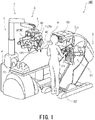
- FIG. 1 is a schematic diagram showing an entire configuration of a surgical system according to one embodiment of the present disclosure.
- FIG. 2 is a block diagram showing the configuration of a control system of the surgical system shown in FIG. 1 .
- a surgical system 100 is a system which performs endoscopic surgery for a patient P by using an operation unit 1 which is operated in such a manner that an operator O, such as a doctor, manipulates a manipulation unit 2 as in robot assisted surgery, robot remote surgery, or the like.
- the surgical system 100 includes the operation unit 1 and the manipulation unit 2 that manipulates the operation unit 1.
- the manipulation unit 2 is arranged away from the operation unit 1, and the operation unit 1 is remotely manipulated by the manipulation unit 2.
- the operator O inputs to the manipulation unit 2 an operation to be performed by the operation unit 1, and the manipulation unit 2 transmits an operating command of the operation to the operation unit 1.
- the operation unit 1 receives the operating command transmitted from the manipulation unit 2 and operates an endoscope assembly 42, a surgical instrument 41, and the like included in the operation unit 1 based on the operating command.
- the manipulation unit 2 constitutes an interface between the surgical system 100 and the operator O and is an apparatus used to manipulate the operation unit 1.
- the manipulation unit 2 is arranged adjacent to or away from an operating table 111 inside an operating room or arranged outside the operating room.
- the manipulation unit 2 includes manipulation inputters, such as a manipulator arm 51 and a manipulation pedal 52, used by the operator O to input the operating command.
- the manipulator arm 51 includes a first hand unit 51a manipulated by the operator O with his/her right hand and a second hand unit 51b manipulated by the operator O with his/her left hand.
- the manipulation unit 2 further includes a monitor 53 that displays an image taken by a camera of the endoscope assembly 42.
- the monitor 53 may be configured as a unit (display unit) arranged separately from the manipulation unit 2 including the manipulation inputters. While visually confirming an affected part on the monitor 53, the operator O manipulates the manipulation inputters to input the operating command to the manipulation unit 2.
- the operating command input to the manipulation unit 2 is transmitted to a below-described controller 6 of the operation unit 1 through wired communication or wireless communication.
- the operation unit 1 constitutes an interface between the surgical system 100 and the patient P.
- the operation unit 1 is arranged adjacent to the operating table 111 on which the patient P lies inside the operating room.
- the inside of the operating room is a sterile field.
- the operation unit 1 includes a positioner 7, a platform 5 attached to a tip end portion of the positioner 7, and patient-side manipulator arms (hereinafter simply referred to as "arms 3") detachably attached to the platform 5.
- the positioner 7 is configured as a multiaxial robot and can three-dimensionally move the position of the platform 5 relative to a base 70 placed at a predetermined position of the operating room.
- the arms 3 and the platform 5 are covered with a sterile drape (not shown) to be shielded from the sterile field in the operating room.
- the platform 5 serves as a "hub" for the arms 3.
- the positioner 7 and the platform 5 constitute a manipulator arm support S that supports the arms 3 such that the arms 3 are movable.
- the manipulator arm support S may include at least the platform 5.
- the manipulator arm support S may include a linear motion rail or a lifting device or may be configured such that the platform 5 is supported by a bracket attached to a ceiling or a wall.
- components from the positioner 7 to the endoscope assembly 42 or each surgical instrument 41 are coupled to each other in series.
- an end portion located closer to the positioner 7 (more specifically, a portion of the positioner 7 which portion contacts a floor of the operating room) is referred to as a "base end portion,” and an opposite end portion is referred to as a "tip end portion.”
- the arms 3 are attachable to and detachable from the platform 5.
- the arms 3 have water resistance, heat resistance, and chemical resistance for a cleaning treatment and a sterilization treatment.
- each of the arms 3 includes: a base detachably attached to the platform 5; and first to sixth links sequentially coupled to each other from the base toward the tip end portion.
- the arm 3 is configured as a seven-axis articulated arm including a redundant axis. Therefore, the arm 3 is configured such that the tip end portion thereof is movable relative to the base end portion thereof in a three-dimensional space. Since the arm 3 includes the redundant axis, the posture of the arm can be changed without changing the position of the tip end portion of the arm 3.
- the arms 3 included in the operation unit 1 are the same in configuration as each other or are similar in configuration to each other. However, at least one of the arms 3 may be different in configuration from the other arms.
- An outer shell of the arm 3 is mainly formed by a member, such as stainless steel, having heat resistance and chemical resistance.
- a seal (not shown) for obtaining water resistance is provided at a coupler between the links.
- the seal has heat resistance corresponding to high pressure steam sterilization and chemical resistance with respect to disinfectant.
- an end portion of one of the links is inserted into an end portion of the other link, and the seal is arranged so as to fill a gap between the end portions of the links, and is therefore hidden in terms of appearance. With this, infiltration of water, chemical liquid, and steam through the gap between the seal and the link is suppressed.
- a holder (instrument holder) 36 (see FIGS. 3 and 4 described below) that can hold the below-described surgical instrument 41 or the below-described endoscope assembly 42 are provided at the tip end portion of each arm 3.
- a translational arm (not shown) may be attached to the tip end portion of the sixth link of the arm 3.
- the holder 36 is provided at the tip end portion of the translational arm.
- a first surgical instrument 41a is detachably held by a tip end portion of a first arm 3A that is one of the arms 3.
- the endoscope assembly 42 is held by a tip end portion of a second arm 3B that is another one of the arms 3.
- a second surgical instrument 41b is detachably held at a tip end portion of a third arm 3C that is yet another one of the arms 3.
- the surgical instruments may be detachably held by the other arms 3.
- FIG. 3 is a diagram showing one example of the surgical instrument according to the present embodiment.
- Each of the surgical instruments 41 (such as the first surgical instrument 41a and the second surgical instrument 41b) includes: a drive unit 45 provided at the base end portion of the surgical instrument 41; an end effector (treatment tool) 44 provided at the tip end portion of the surgical instrument 41; and a thin and long shaft 43 coupling the drive unit 45 and the end effector 44.
- the base end portion of the surgical instrument 41 is attachable to and detachable from the holder 36 of each arm 3.
- a long-axis direction D is defined at the surgical instrument 41.
- the drive unit 45, the shaft 43, and the end effector 44 are arranged along the long-axis direction D.
- the end effector 44 of the surgical instrument 41 is selected from the group consisting of tools (such as a pair of forceps, a pair of scissors, a grasper, a needle holder, a microdissector, a staple applier, a tucker, a suction cleaning tool, a snare wire, and a clip applier) each having an operating joint and tools (such as a cutting blade, a cautery probe, a washer, a catheter, and a suction orifice) each not having a joint.
- FIG. 3 shows a pair of forceps including a pair of open-close claws (gripping pieces).
- the surgical instrument 41 includes an instrument bendable portion 46 that bends the shaft 43 relative to the long-axis direction D.
- the instrument bendable portion 46 is bendable in a predetermined plane (bent plane).
- the long-axis direction D when the instrument bendable portion 46 is bent is defined as an extending direction of the shaft 43 including the instrument bendable portion 46.
- the long-axis direction D changes in accordance with the bending of the instrument bendable portion 46.
- the shaft 43 is rotatable about a long axis relative to a base portion (drive unit 45) of the surgical instrument 41 at a base end portion of the shaft 43 (see a base end-side rotating shaft 50 in FIG. 3 ). Therefore, since the bent plane rotates about the long axis by the rotation of the shaft 43 about the long axis, a bending direction of the instrument bendable portion 46 can be set three-dimensionally.
- the bending operation of the instrument bendable portion 46 is realized by a known configuration, such as a hydraulic configuration or a mechanical configuration including wires extending therein.
- the surgical instrument 41 further includes a tip end-side rotating shaft 49 at a tip end portion of the shaft 43 (instrument bendable portion 46). With this, the end effector 44 is rotatable about the long axis relative to the shaft 43. Moreover, when the end effector 44 is the forceps unit shown in FIG. 3 , the end effector 44 includes a gripping pieces spindle 44a by which tip end portions of the gripping pieces open or close (i.e., by which gripping and releasing are switched). As above, the surgical instrument 41 includes, as moving parts, the base end-side rotating shaft 50, the instrument bendable portion 46, the tip end-side rotating shaft 49, and the gripping pieces spindle 44a.
- FIG. 4 is a diagram showing one example of the endoscope assembly according to the present embodiment.
- the endoscope assembly 42 includes the drive unit 45, the base end-side rotating shaft 50, the shaft 43, the tip end-side rotating shaft 49, and the camera 47.
- An image taken by the camera 47 is displayed on the monitor 53 of the manipulation unit 2.
- Abase end portion of the endoscope assembly 42 is attachable to and detachable from the holder 36 of the arm 3.
- the endoscope assembly 42 may be undetachably attached to the holder 36 of the arm 3.
- the operation unit 1 may include an arm dedicated for the endoscope assembly 42.
- the endoscope assembly 42 includes an endoscope bendable portion 48 that bends the shaft 43 relative to the long-axis direction D.
- the endoscope bendable portion 48 is similar in configuration to the instrument bendable portion 46 of the surgical instrument 41.
- the shaft 43 is rotatable about the long axis relative to the base portion (drive unit 45) of the surgical instrument 41 at the base end portion of the shaft 43. Therefore, since the bent plane rotates about the long axis by the rotation of the shaft 43 about the long axis, the bending direction of the endoscope bendable portion 48 can be set three-dimensionally.
- the operation unit 1 is controlled by a controller 6.
- the controller 6 is constituted by a computer, such as a microcontroller.
- the controller 6 is configured as a processing circuit including a processor, a volatile memory, a non-volatile memory, an I/O interface, and the like.
- the controller 6 which has received the operating command from the manipulation unit 2 operates the positioner 7 to position the platform 5 such that a predetermined positional relation between the platform 5 and the operating table 111 or between the platform 5 and the patient P is realized.
- the controller 6 operates the arms 3 to position the endoscope assembly 42 and the surgical instruments 41 such that a predetermined initial positional relation among a sleeve (cannula sleeve) 110 placed on a body surface of the patient P, the endoscope assembly 42, and the surgical instruments 41 is realized.
- the positioning operation of the positioner 7 and the positioning operations of the arms 3 may be performed at the same time.
- the controller 6 performs the surgery by operating the surgical instruments 41 by the arms 3 in accordance with the operating command from the manipulation unit 2 while suitably changing the positions and postures of the endoscope assembly 42 and the surgical instruments 41.
- the arms 3 are respectively assigned to the first hand unit 51a and the second hand unit 51b of the manipulation unit 2 so as to be manipulated by the first hand unit 51a and the second hand unit 51b.
- the first arm 3A is assigned to the first hand unit 51a
- the third arm 3C is assigned to the second hand unit 51b.
- the operating command for the first arm 3A holding the first surgical instrument 41a is generated by a manipulation input to the first hand unit 51a
- the operating command for the third arm 3C holding the second surgical instrument 41b is generated by a manipulation input to the second hand unit 51b.
- Each of the arms 3 assigned to the hand units 51a and 51b is selected from the arms 3 by manipulating the manipulation unit 2.
- the arms 3 which operate by manipulating the hand units 51a and 51b can be switched even during the surgery.
- the arm 3 assigned to the second hand unit 51b in the above example is switched from the third arm 3C to the second arm 3B.
- the operating command for the second arm 3B holding the endoscope assembly 42 is generated by a manipulation input to the second hand unit 51b.
- the operating commands that operate the bendable portion 46 of the surgical instrument 41 and the bendable portion 48 of the endoscope assembly 42 can also be generated by manipulation inputs to the hand units 51a and 51b.
- the controller 6 controls the movements of the arms 3 based on the operating commands.
- the controller 6 controls the rotation of each servomotor (not shown) that drives a shaft of the corresponding arm 3 through an amplifying circuit and the like.
- a rotation angle of the servomotor is detected by a corresponding encoder, and a drive command value for the servomotor is generated based on the rotation angle and the operating command.
- the servomotor is servo-controlled such that the position and posture of the tip end portion of the arm 3 reaches the position and posture that are based on the operating command.
- the surgical system 100 includes a storage 60 that stores data readable by the controller 6.
- the storage 60 prestores surgical information input through the manipulation unit 2.
- the surgical information contains a combination of the arms 3 to be used in the surgery.
- the storage 60 stores information, such as the length of the surgical instrument (the endoscope assembly 42 or the surgical instrument 41), held by the tip end portion of the arm 3, in the long-axis direction D.
- the controller 6 can recognize position coordinates of the tip end portions of the surgical instrument 41 and the endoscope assembly 42 held by the tip end portions of the arms 3.
- the controller 6 can execute bending following control of controlling the endoscope assembly 42 such that the endoscope assembly 42 is bent to follow the bending of the instrument bendable portion 46 of the surgical instrument 41 which is bent based on the operating command.
- the manipulation unit 2 is configured to receive a manipulation input by which whether to perform the bending following control is switched.
- the controller 6 controls the endoscope assembly 42 such that the endoscope assembly 42 is bent to follow the bending of the first surgical instrument 41a.
- the direction of the image taken by the camera 47 of the endoscope assembly 42 can be easily adjusted in accordance with the movement of the tip end portion of the first surgical instrument 41a to a direction in which the tip end portion of the first surgical instrument 41a is directed.
- the image of the tip end portion of the first surgical instrument 41a can be easily acquired.
- the controller 6 determines a bending angle ⁇ C of the endoscope bendable portion 48 of the endoscope assembly 42 in accordance with a bending angle ⁇ H of the instrument bendable portion 46 of the first surgical instrument 41a. For example, when the bending angle ⁇ C is equal to the bending angle ⁇ H , the controller 6 controls the second arm 3B and the endoscope assembly 42 such that the endoscope bendable portion 48 is bent at a bending angle that is equal to the bending angle ⁇ H of the instrument bendable portion 46 of the first surgical instrument 41a.
- a relation between the bending angle ⁇ H of the instrument bendable portion 46 and the bending angle ⁇ C of the endoscope bendable portion 48 is not limited to the above relation.
- the relation between the bending angle ⁇ H of the instrument bendable portion 46 and the bending angle ⁇ C of the endoscope bendable portion 48 may change in accordance with the bending angle ⁇ H of the instrument bendable portion 46.
- a coefficient k by which the bending angle ⁇ C of the endoscope bendable portion 48 is multiplied may increase (or decrease) as the bending angle ⁇ H of the instrument bendable portion 46 increases.
- the bending of the endoscope assembly 42 can be made to follow the bending of the first surgical instrument 41a by simple control.
- the endoscope assembly 42 and the second arm 3B holding the endoscope assembly 42 can operate based on the manipulation of the operator O by setting the second arm 3B as a target to be manipulated by the first hand unit 51a or the second hand unit 51b. Therefore, the position and posture of the endoscope assembly 42 can be adjusted based on the manipulation of the operator O such that after the bending operation of the endoscope assembly 42 is performed so as to follow the bending of the first surgical instrument 41a, an image region more desirable for the operator O is displayed on the monitor 53.
- the amount of adjustment by the manipulation of the operator O can be made small by executing the bending following control of the endoscope assembly 42 in advance.
- the controller 6 performs first calculation processing of determining the position and posture of the endoscope assembly 42 such that when the first surgical instrument 41a is bent, a relative relation between the position and posture of the tip end portion of the first surgical instrument 41a before the instrument bendable portion 46 is bent and the position and posture of the tip end portion of the endoscope assembly 42 before the endoscope bendable portion 48 is bent is maintained.
- the storage 60 stores the position and posture of the tip end portion of the first surgical instrument 41a before the instrument bendable portion 46 is bent and the position and posture of the tip end portion of the endoscope assembly 42 before the endoscope bendable portion 48 is bent.
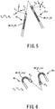
- FIG. 5 is a partially enlarged view showing the first surgical instrument and the endoscope assembly before the first surgical instrument and the endoscope assembly are bent in the second control mode of the present embodiment.
- FIG. 6 is a partially enlarged view showing the first surgical instrument and the endoscope assembly after the endoscope assembly has followed the bending operation of the first surgical instrument in the second control mode of the present embodiment.
- both the bending angle ⁇ H of the instrument bendable portion 46 of the first surgical instrument 41a and the bending angle ⁇ C of the endoscope bendable portion 48 of the endoscope assembly 42 are zero.
- a coordinate system (first surgical instrument coordinate system) of the tip end portion of the first surgical instrument 41a is represented by ⁇ H1
- a coordinate system (endoscope assembly coordinate system) of the tip end portion of the endoscope assembly 42 is represented by ⁇ C1
- a relative relation between a matrix P C1 indicating the position and posture of the endoscope assembly coordinate system ⁇ C1 of the tip end portion of the endoscope assembly 42 before the bending and a matrix P H1 indicating the position and posture of the first surgical instrument coordinate system ⁇ H1 of the tip end portion of the first surgical instrument 41a before the bending is represented by Formula (1) below.
- C1 T H1 indicates a homogeneous transformation matrix when the position and posture of the first surgical instrument coordinate system ⁇ H1 are viewed from the endoscope assembly coordinate system ⁇ C1 .
- the homogeneous transformation matrix C1 T H1 is represented as below by using: the position coordinate (X, Y, Z) of the tip end portion of the first surgical instrument 41a in the endoscope assembly coordinate system ⁇ C1 ; an x-axis unit vector component (n x , n y , n z ) of the first surgical instrument coordinate system ⁇ H1 when viewed from the endoscope assembly coordinate system ⁇ C1 ; a y-axis unit vector component (o x , o y , o z ) of the first surgical instrument coordinate system ⁇ H1 when viewed from the endoscope assembly coordinate system ⁇ C1 ; and a z-axis unit vector component (a x , a y , a z ) of the first surgical instrument coordinate system ⁇ H1 when viewed from the endoscope assembly coordinate system ⁇ C1 .
- the unit vector component (3 ⁇ 3 matrix represented by n i , o i , a i (i denotes x, y, or z)) of each axis of the first surgical instrument coordinate system ⁇ H1 when viewed from the endoscope assembly coordinate system ⁇ C1 indicates the posture of the tip end portion of the first surgical instrument 41a when viewed from the tip end portion of the endoscope assembly 42.
- the storage 60 stores the homogeneous transformation matrix C1 T H1 as the above relative relation. Then, when the operating command containing the bending operation of bending the instrument bendable portion 46 has been generated as the operating command for the first surgical instrument 41a, the controller 6 calculates a matrix P C2 indicating the position and posture of the tip end portion of the endoscope assembly 42 which follows the movement of the first surgical instrument 41a, by using a matrix P H2 indicating the position and posture of the tip end portion of the first surgical instrument 41a at the time of the bending and the above homogeneous transformation matrix C1 T H1 .
- the controller 6 calculates and obtains, by inverse transformation, the bending angle ⁇ C of the endoscope bendable portion 48 of the endoscope assembly 42 and the position and posture (displacement magnitude of each joint shaft of the second arm 3B) of the second arm 3B holding the endoscope assembly 42 such that the position and posture of the tip end portion of the endoscope assembly 42 become the position and posture represented by the matrix P C2 indicating the calculated position and posture.
- the controller 6 controls the bending operation of the endoscope bendable portion 48 of the endoscope assembly 42 and the operation of the second arm 3B based on the calculation result.
- the endoscope assembly 42 is subjected to the bending following control such that the relative relation between the position and posture of the tip end portion of the first surgical instrument 41a and the position and posture of the tip end portion of the endoscope assembly 42 is maintained before and after the bending operation of the first surgical instrument 41a.
- the bending operation of the first surgical instrument 41a and the bending operation of the endoscope assembly 42 are performed in a state where the relative relation between the position and posture of the tip end portion of the first surgical instrument 41a and the position and posture of the tip end portion of the endoscope assembly 42 is maintained. Therefore, the image region taken by the camera 47 of the endoscope assembly 42 for the tip end portion of the first surgical instrument 41a is maintained before and after the bending.
- the position and posture of the endoscope assembly 42 can be adjusted based on the manipulation of the operator O such that the image region more desirable for the operator O is displayed on the monitor 53. According to the second control mode, the amount of adjustment of the endoscope assembly 42 by the manipulation of the operator O after the bending operation of the first surgical instrument 41a can be made smaller.
- the position of the endoscope assembly 42 cannot be determined in the above first calculation processing such that the above relative relation is maintained.
- the position of the endoscope assembly 42 cannot be determined when there are plural combinations of the bending angle ⁇ C of the endoscope bendable portion 48 and the position and posture of the second arm 3B corresponding to the matrix P C2 indicating the position and posture after the bending following operation (i.e., when there are plural solutions).
- the tip end portion of the endoscope assembly 42 cannot reach a position where the tip end portion of the endoscope assembly 42 should reach after the bending following operation, due to other constraint conditions, such as restriction of a moving range of the second arm 3B, interference with other arms, and the position of the sleeve 11 (a position through which the shaft 43 of the endoscope assembly 42 has to pass) (i.e., a case where there is no solution).
- the controller 6 may determine the posture of the tip end portion of the endoscope assembly 42 such that a relation between the posture of the tip end portion of the first surgical instrument 41a before the instrument bendable portion 46 is bent and the posture of the tip end portion of the endoscope assembly 42 before the endoscope bendable portion 48 is bent is maintained.
- the bending angle ⁇ C of the endoscope bendable portion 48 of the endoscope assembly 42 and the position of the second arm 3B may be controlled such that the relation between those postures is maintained.
- the controller 6 operates such that the relation between the posture of the tip end portion of the first surgical instrument 41a and the posture of the tip end portion of the endoscope assembly 42 is maintained. Therefore, the endoscope assembly 42 can be made to follow the bending operation of the first surgical instrument 41a as much as possible.
- the bending angle ⁇ C of the endoscope bendable portion 48 of the endoscope assembly 42 may be determined in accordance with the bending angle ⁇ H of the instrument bendable portion 46 of the first surgical instrument 41a.
- the controller 6 may switch to the first control mode.
- the bending angle ⁇ C of the endoscope bendable portion 48 of the endoscope assembly 42 is determined in accordance with the bending angle ⁇ H of the instrument bendable portion 46 of the first surgical instrument 41a. Therefore, the endoscope assembly 42 can be made to follow the bending operation of the first surgical instrument 41a as much as possible.
- the endoscope assembly 42 (and the second arm 3B) operates so as to follow the bending operation of the first surgical instrument 41a held by the first arm 3A.
- the endoscope assembly 42 (and the second arm 3B) may be able to operate so as to follow the bending operation of the surgical instrument 41 held by the arm 3 other than the first arm 3A.
- the endoscope assembly 42 (and the second arm 3B) may be able to operate so as to follow the bending operation of the second surgical instrument 41b held by the third arm 3C.
- the surgical instrument that the endoscope assembly 42 follows may be selectable from the first surgical instrument 41a and the second surgical instrument 41b.
- a changing-over switch (not shown) for the bending following control may be provided at the manipulation unit 2.
- the changing-over switch may switch among following the arm 3 assigned to the first hand unit 51a, following the arm 3 assigned to the second hand unit 51b, and non-following.
- the non-following is selected by the changing-over switch, and the first surgical instrument 41a or the second surgical instrument 41b performs the bending operation, the endoscope bendable portion 48 of the endoscope assembly 42 does not follow the bending operation.
- the endoscope assembly 42 can be made to independently perform the bending operation by manipulating the hand unit 51a or 51b.
- the controller 6 controls the endoscope assembly 42 and the second arm 3B such that the endoscope assembly 42 and the second arm 3B follow the bending operation of the surgical instrument 41a or 41b.
- the controller 6 may perform a control operation of not performing the bending following control for the endoscope assembly 42 and the second arm 3B (automatically cancel the following) regardless of the bending operation of the instrument bendable portion 46 of the first surgical instrument 41a. Instead of this, even when the second arm 3B holding the endoscope assembly 42 is assigned to the hand unit 51a or 51b, the controller 6 may execute the bending following control.
- controller 6 may be able to set the surgical instrument 41a or 41b as a target to be followed by the endoscope assembly 42, by the manipulation of the manipulation unit 2 regardless of the assignment of the hand units 51a and 51b.
- the method of controlling the surgical system and the surgical system according to the present disclosure are useful to easily acquire an image of a tip end portion of a surgical instrument attached to a manipulator arm even when the surgical instrument is bent.
Abstract
Description
- The present disclosure relates to a method of controlling a surgical system and the surgical system.
- Known is a master-slave system which includes manipulator arms and performs surgery by moving the manipulator arms based on manipulation of an operator (see
PTLs PTL 3, for example). -
- PTL 1: Published Japanese Translation of
PCT Application No. 2017-515524 - PTL 2: Published Japanese Translation of
PCT Application No. 2017-513550 - PTL 3:
Japanese Laid-Open Patent Application Publication No. 2013-220107 - According to the above surgical system, an endoscope assembly including a camera at a tip end portion thereof is attached to one of the manipulators. While watching images taken by the camera of the endoscope assembly, the operator performs surgery by using the other manipulator arms.
- Moreover, in the above surgical system, the manipulator arms are attached to a single arm base (also called a platform). Furthermore, for example, in laparoscopic surgery performed by using the surgical system, to reduce invasiveness at a surgical site of a patient, largely cutting an abdomen of the patient is not performed, but one or several openings are made at the abdomen of the patient. Then, the surgical instrument and the endoscope assembly are introduced into the body of the patient through the openings. To reduce the invasiveness at the surgical site of the patient, it is preferable that the number of openings be small.
- Due to the above restriction, the tip end portions of the manipulator arms are directed in substantially the same direction. Therefore, typically, the image taken by the camera of the endoscope assembly shows parts located in a deeper direction of the tip end portion of the surgical instrument (i.e., a direction from the base end portion of the surgical instrument to the tip end portion of the surgical instrument).
- However, when an instrument including a bendable portion is attached as the surgical instrument to the manipulator arm, the surgical instrument can take such position and posture that the tip end portion of the surgical instrument is directed toward the base end of the manipulator arm. In this case, to appropriately take an image of the surgical site, it is desirable that the image taken by the camera of the endoscope assembly shows parts located in a shallower direction of the tip end portion of the surgical instrument. However, due to the above restriction, there is a limit to arrange the manipulator arm to which the endoscope assembly is attached, such that the endoscope assembly can take an image of parts located at a farther side (for example, the base end side of the surgical instrument) of the tip end portion of the surgical instrument that is bent.
- Increasing the number of openings to realize the arrangement of the endoscope assembly leads to a burden on the patient. Moreover, it is troublesome for the operator to adjust the arrangement of the endoscope assembly when bending the surgical instrument.
- The present disclosure was made to solve the above problems, and an object of the present disclosure is to provide a method of controlling a surgical system and the surgical system, each of which can easily acquire an image of a tip end portion of a surgical instrument attached to a manipulator arm even when the surgical instrument is bent.
- One aspect of the present disclosure is a method of controlling a surgical system, the surgical system including: manipulator arms including respective instrument holders at tip end portions of the manipulator arms, the instrument holders holding respective long-axis surgical instruments, the tip end portions of the manipulator arms being three-dimensionally movable relative to corresponding base end portions of the manipulator arms; a manipulation unit that generates, based on a manipulation input, an operating command that moves the manipulator arms; and a controller that controls movements of the manipulator arms based on the operating command. The manipulator arms include a first manipulator arm including the instrument holder holding a first surgical instrument including an instrument bendable portion and a second manipulator arm including the instrument holder holding an endoscope assembly including an endoscope bendable portion and a camera at a tip end portion of the endoscope assembly. The method includes controlling the endoscope assembly such that the endoscope assembly is bent so as to follow bending of the first surgical instrument that is bent based on the operating command.
- According to the above control method, the first surgical instrument and the endoscope assembly are bendable, and the endoscope assembly is controlled such that the endoscope assembly is bent so as to follow the bending of the first surgical instrument. Therefore, the direction of an image taken by the camera of the endoscope assembly is easily adjusted in accordance with the movement of the tip end portion of the first surgical instrument to a direction in which the tip end portion of the first surgical instrument is directed. Thus, even when the first surgical instrument is bent, the image of the tip end portion of the first surgical instrument can be easily acquired.
- A bending angle of the endoscope bendable portion of the endoscope assembly may be determined in accordance with a bending angle of the instrument bendable portion of the first surgical instrument. According to this, the bending of the endoscope assembly can be made to follow the bending of the first surgical instrument by simple control.
- The surgical system may include a storage that stores data readable by the controller. The storage may store a position and posture of a tip end portion of the first surgical instrument before the instrument bendable portion is bent and a position and posture of the tip end portion of the endoscope assembly before the endoscope bendable portion is bent. The method may include performing, when the first surgical instrument is bent, first calculation processing of determining the position and posture of the endoscope assembly such that a relative relation between the position and posture of the tip end portion of the first surgical instrument before the instrument bendable portion is bent and the position and posture of the tip end portion of the endoscope assembly before the endoscope bendable portion is bent is maintained. According to this, the bending operation of the first surgical instrument and the bending operation of the endoscope assembly are performed in a state where the relative relation between the position and posture of the tip end portion of the first surgical instrument and the position and posture of the tip end portion of the endoscope assembly is maintained. Therefore, the image region taken by the camera of the endoscope assembly for the tip end portion of the first surgical instrument is maintained before and after the bending. Thus, the adjustment of the endoscope assembly after the bending operation of the first surgical instrument can be reduced.
- When the position of the endoscope assembly is undeterminable in the first calculation processing such that the relative relation is maintained, the posture of the tip end portion of the endoscope assembly may be determined such that a relation between the posture of the tip end portion of the first surgical instrument before the instrument bendable portion is bent and the posture of the tip end portion of the endoscope assembly before the endoscope bendable portion is bent is maintained. According to this, even when the relative relation between the position and posture of the tip end portion of the first surgical instrument and the position and posture of the tip end portion of the endoscope assembly cannot be maintained, the surgical system operates such that the relation between the posture of the tip end portion of the first surgical instrument and the posture of the tip end portion of the endoscope assembly is maintained. Therefore, the endoscope assembly can be made to follow the bending operation of the first surgical instrument as much as possible.
- When the position of the endoscope assembly is undeterminable in the first calculation processing such that the relative relation is maintained, a bending angle of the endoscope bendable portion of the endoscope assembly may be determined in accordance with a bending angle of the instrument bendable portion of the first surgical instrument. According to this, even when the relative relation between the position and posture of the tip end portion of the first surgical instrument and the position and posture of the tip end portion of the endoscope assembly cannot be maintained, the bending angle of the endoscope bendable portion of the endoscope assembly is determined in accordance with the bending angle of the instrument bendable portion of the first surgical instrument. Therefore, the endoscope assembly can be made to follow the bending operation of the first surgical instrument as much as possible.
- The first calculation processing may be performed based on a constraint condition that the bending angle of the endoscope bendable portion of the endoscope assembly corresponds to the bending angle of the instrument bendable portion of the first surgical instrument. With this, the calculation of the position and posture of the endoscope assembly based on the bending of the endoscope assembly can be performed, and the amount of calculation can be reduced.
- The manipulator arms may include a third manipulator arm including the instrument holder holding a second surgical instrument including an instrument bendable portion. In the method, the endoscope assembly may be bendable so as to follow bending of the second surgical instrument that is bent based on the operating command. A surgical instrument to be followed by the endoscope assembly may be selectable from the first surgical instrument and the second surgical instrument. With this, when there are the plural manipulator arms to which the surgical instruments are attached, an image of a part that an operator wants to see can be easily acquired.
- A surgical system according to another aspect of the present disclosure includes: manipulator arms including respective instrument holders at tip end portions of the manipulator arms, the instrument holders holding respective long-axis surgical instruments, the tip end portions of the manipulator arms being three-dimensionally movable relative to corresponding base end portions of the manipulator arms; a manipulation unit that generates, based on a manipulation input, an operating command that moves the manipulator arms; and a controller that controls movements of the manipulator arms based on the operating command. The manipulator arms include a first manipulator arm including the instrument holder holding a first surgical instrument including an instrument bendable portion and a second manipulator arm including the instrument holder holding an endoscope assembly including an endoscope bendable portion and a camera at a tip end portion of the endoscope assembly. The controller controls the endoscope assembly such that the endoscope assembly is bent so as to follow bending of the first surgical instrument that is bent based on the operating command.
- According to the above configuration, the first surgical instrument and the endoscope assembly are bendable, and the endoscope assembly is controlled such that the endoscope assembly is bent so as to follow the bending of the first surgical instrument. Therefore, the direction of an image taken by the camera of the endoscope assembly is easily adjusted in accordance with the movement of the tip end portion of the first surgical instrument to a direction in which the tip end portion of the first surgical instrument is directed. Thus, even when the first surgical instrument is bent, the image of the tip end portion of the first surgical instrument can be easily acquired.
- The above object, other objects, features, and advantages of the present disclosure will be made clear by the following detailed explanation of preferred embodiments with reference to the attached drawings.
- The present disclosure has an effect of being able to easily acquire an image of a tip end portion of a surgical instrument attached to a manipulator arm even when the surgical instrument is bent.
-
-
FIG. 1 is a schematic diagram showing an entire configuration of a surgical system according to one embodiment of the present disclosure. -
FIG. 2 is a block diagram showing the configuration of a control system of the surgical system shown inFIG. 1 . -
FIG. 3 is a diagram showing one example of a surgical instrument according to the present embodiment. -
FIG. 4 is a diagram showing one example of an endoscope assembly according to the present embodiment. -
FIG. 5 is a partially enlarged view showing a first surgical instrument and the endoscope assembly before the first surgical instrument and the endoscope assembly are bent in a second control mode of the present embodiment. -
FIG. 6 is a partially enlarged view showing the first surgical instrument and the endoscope assembly after the endoscope assembly has followed a bending operation of the first surgical instrument in the second control mode of the present embodiment. - Hereinafter, an embodiment of the present disclosure will be described with reference to the drawings. However, the present disclosure is not limited to the present embodiment. Moreover, in the following description and the drawings, the same reference signs are used for the same or corresponding components, and the repetition of the same explanation is avoided.
-
FIG. 1 is a schematic diagram showing an entire configuration of a surgical system according to one embodiment of the present disclosure.FIG. 2 is a block diagram showing the configuration of a control system of the surgical system shown inFIG. 1 . As shown inFIG. 1 , asurgical system 100 is a system which performs endoscopic surgery for a patient P by using anoperation unit 1 which is operated in such a manner that an operator O, such as a doctor, manipulates amanipulation unit 2 as in robot assisted surgery, robot remote surgery, or the like. - The
surgical system 100 includes theoperation unit 1 and themanipulation unit 2 that manipulates theoperation unit 1. Themanipulation unit 2 is arranged away from theoperation unit 1, and theoperation unit 1 is remotely manipulated by themanipulation unit 2. The operator O inputs to themanipulation unit 2 an operation to be performed by theoperation unit 1, and themanipulation unit 2 transmits an operating command of the operation to theoperation unit 1. Theoperation unit 1 receives the operating command transmitted from themanipulation unit 2 and operates anendoscope assembly 42, asurgical instrument 41, and the like included in theoperation unit 1 based on the operating command. - The
manipulation unit 2 constitutes an interface between thesurgical system 100 and the operator O and is an apparatus used to manipulate theoperation unit 1. Themanipulation unit 2 is arranged adjacent to or away from an operating table 111 inside an operating room or arranged outside the operating room. Themanipulation unit 2 includes manipulation inputters, such as amanipulator arm 51 and amanipulation pedal 52, used by the operator O to input the operating command. In the present embodiment, themanipulator arm 51 includes afirst hand unit 51a manipulated by the operator O with his/her right hand and asecond hand unit 51b manipulated by the operator O with his/her left hand. - The
manipulation unit 2 further includes amonitor 53 that displays an image taken by a camera of theendoscope assembly 42. Themonitor 53 may be configured as a unit (display unit) arranged separately from themanipulation unit 2 including the manipulation inputters. While visually confirming an affected part on themonitor 53, the operator O manipulates the manipulation inputters to input the operating command to themanipulation unit 2. The operating command input to themanipulation unit 2 is transmitted to a below-describedcontroller 6 of theoperation unit 1 through wired communication or wireless communication. - The
operation unit 1 constitutes an interface between thesurgical system 100 and the patient P. Theoperation unit 1 is arranged adjacent to the operating table 111 on which the patient P lies inside the operating room. The inside of the operating room is a sterile field. - The
operation unit 1 includes a positioner 7, aplatform 5 attached to a tip end portion of the positioner 7, and patient-side manipulator arms (hereinafter simply referred to as "arms 3") detachably attached to theplatform 5. The positioner 7 is configured as a multiaxial robot and can three-dimensionally move the position of theplatform 5 relative to a base 70 placed at a predetermined position of the operating room. Thearms 3 and theplatform 5 are covered with a sterile drape (not shown) to be shielded from the sterile field in the operating room. - In the
operation unit 1, theplatform 5 serves as a "hub" for thearms 3. In the present embodiment, the positioner 7 and theplatform 5 constitute a manipulator arm support S that supports thearms 3 such that thearms 3 are movable. However, the manipulator arm support S may include at least theplatform 5. For example, instead of the positioner 7, the manipulator arm support S may include a linear motion rail or a lifting device or may be configured such that theplatform 5 is supported by a bracket attached to a ceiling or a wall. - In the
above operation unit 1, components from the positioner 7 to theendoscope assembly 42 or eachsurgical instrument 41 are coupled to each other in series. In the present description, regarding each of these components, an end portion located closer to the positioner 7 (more specifically, a portion of the positioner 7 which portion contacts a floor of the operating room) is referred to as a "base end portion," and an opposite end portion is referred to as a "tip end portion." - The
arms 3 are attachable to and detachable from theplatform 5. Thearms 3 have water resistance, heat resistance, and chemical resistance for a cleaning treatment and a sterilization treatment. There are various methods as the sterilization treatment of thearms 3. For example, high pressure steam sterilization, EOG sterilization, chemical sterilization using disinfectant, or the like may be selectively used. - Although not shown in detail, each of the
arms 3 includes: a base detachably attached to theplatform 5; and first to sixth links sequentially coupled to each other from the base toward the tip end portion. Thearm 3 is configured as a seven-axis articulated arm including a redundant axis. Therefore, thearm 3 is configured such that the tip end portion thereof is movable relative to the base end portion thereof in a three-dimensional space. Since thearm 3 includes the redundant axis, the posture of the arm can be changed without changing the position of the tip end portion of thearm 3. In the present embodiment, thearms 3 included in theoperation unit 1 are the same in configuration as each other or are similar in configuration to each other. However, at least one of thearms 3 may be different in configuration from the other arms. - An outer shell of the
arm 3 is mainly formed by a member, such as stainless steel, having heat resistance and chemical resistance. Moreover, a seal (not shown) for obtaining water resistance is provided at a coupler between the links. The seal has heat resistance corresponding to high pressure steam sterilization and chemical resistance with respect to disinfectant. Regarding the coupler between the links, an end portion of one of the links is inserted into an end portion of the other link, and the seal is arranged so as to fill a gap between the end portions of the links, and is therefore hidden in terms of appearance. With this, infiltration of water, chemical liquid, and steam through the gap between the seal and the link is suppressed. - A holder (instrument holder) 36 (see
FIGS. 3 and 4 described below) that can hold the below-describedsurgical instrument 41 or the below-describedendoscope assembly 42 are provided at the tip end portion of eacharm 3. A translational arm (not shown) may be attached to the tip end portion of the sixth link of thearm 3. In this case, theholder 36 is provided at the tip end portion of the translational arm. With this, when theholder 36 of the translational arm is made to perform a translational movement in a long-axis direction, thesurgical instrument 41 or theendoscope assembly 42 attached to theholder 36 can be made to perform a translational movement in the long-axis direction. - As shown in
FIG. 2 , a firstsurgical instrument 41a is detachably held by a tip end portion of afirst arm 3A that is one of thearms 3. Theendoscope assembly 42 is held by a tip end portion of asecond arm 3B that is another one of thearms 3. A secondsurgical instrument 41b is detachably held at a tip end portion of athird arm 3C that is yet another one of thearms 3. Although not shown, the surgical instruments may be detachably held by theother arms 3. -
FIG. 3 is a diagram showing one example of the surgical instrument according to the present embodiment. Each of the surgical instruments 41 (such as the firstsurgical instrument 41a and the secondsurgical instrument 41b) includes: adrive unit 45 provided at the base end portion of thesurgical instrument 41; an end effector (treatment tool) 44 provided at the tip end portion of thesurgical instrument 41; and a thin andlong shaft 43 coupling thedrive unit 45 and theend effector 44. The base end portion of thesurgical instrument 41 is attachable to and detachable from theholder 36 of eacharm 3. - A long-axis direction D is defined at the
surgical instrument 41. Thedrive unit 45, theshaft 43, and theend effector 44 are arranged along the long-axis direction D. Theend effector 44 of thesurgical instrument 41 is selected from the group consisting of tools (such as a pair of forceps, a pair of scissors, a grasper, a needle holder, a microdissector, a staple applier, a tucker, a suction cleaning tool, a snare wire, and a clip applier) each having an operating joint and tools (such as a cutting blade, a cautery probe, a washer, a catheter, and a suction orifice) each not having a joint.FIG. 3 shows a pair of forceps including a pair of open-close claws (gripping pieces). - In the present embodiment, the
surgical instrument 41 includes an instrumentbendable portion 46 that bends theshaft 43 relative to the long-axis direction D. The instrumentbendable portion 46 is bendable in a predetermined plane (bent plane). In the present embodiment, the long-axis direction D when the instrumentbendable portion 46 is bent is defined as an extending direction of theshaft 43 including the instrumentbendable portion 46. To be specific, the long-axis direction D changes in accordance with the bending of the instrumentbendable portion 46. - Moreover, the
shaft 43 is rotatable about a long axis relative to a base portion (drive unit 45) of thesurgical instrument 41 at a base end portion of the shaft 43 (see a base end-siderotating shaft 50 inFIG. 3 ). Therefore, since the bent plane rotates about the long axis by the rotation of theshaft 43 about the long axis, a bending direction of the instrumentbendable portion 46 can be set three-dimensionally. The bending operation of the instrumentbendable portion 46 is realized by a known configuration, such as a hydraulic configuration or a mechanical configuration including wires extending therein. - The
surgical instrument 41 further includes a tip end-siderotating shaft 49 at a tip end portion of the shaft 43 (instrument bendable portion 46). With this, theend effector 44 is rotatable about the long axis relative to theshaft 43. Moreover, when theend effector 44 is the forceps unit shown inFIG. 3 , theend effector 44 includes a gripping pieces spindle 44a by which tip end portions of the gripping pieces open or close (i.e., by which gripping and releasing are switched). As above, thesurgical instrument 41 includes, as moving parts, the base end-siderotating shaft 50, the instrumentbendable portion 46, the tip end-siderotating shaft 49, and thegripping pieces spindle 44a. -
FIG. 4 is a diagram showing one example of the endoscope assembly according to the present embodiment. Instead of theend effector 44 of thesurgical instrument 41, acamera 47 is attached to a tip end portion of theendoscope assembly 42. Therefore, theendoscope assembly 42 includes thedrive unit 45, the base end-siderotating shaft 50, theshaft 43, the tip end-siderotating shaft 49, and thecamera 47. An image taken by thecamera 47 is displayed on themonitor 53 of themanipulation unit 2. Abase end portion of theendoscope assembly 42 is attachable to and detachable from theholder 36 of thearm 3. Instead of this, theendoscope assembly 42 may be undetachably attached to theholder 36 of thearm 3. To be specific, theoperation unit 1 may include an arm dedicated for theendoscope assembly 42. - The
endoscope assembly 42 includes an endoscopebendable portion 48 that bends theshaft 43 relative to the long-axis direction D. The endoscopebendable portion 48 is similar in configuration to the instrumentbendable portion 46 of thesurgical instrument 41. In theendoscope assembly 42, theshaft 43 is rotatable about the long axis relative to the base portion (drive unit 45) of thesurgical instrument 41 at the base end portion of theshaft 43. Therefore, since the bent plane rotates about the long axis by the rotation of theshaft 43 about the long axis, the bending direction of the endoscopebendable portion 48 can be set three-dimensionally. - The
operation unit 1 is controlled by acontroller 6. Thecontroller 6 is constituted by a computer, such as a microcontroller. Thecontroller 6 is configured as a processing circuit including a processor, a volatile memory, a non-volatile memory, an I/O interface, and the like. - In surgery performed by using the
operation unit 1 configured as above, first, thecontroller 6 which has received the operating command from themanipulation unit 2 operates the positioner 7 to position theplatform 5 such that a predetermined positional relation between theplatform 5 and the operating table 111 or between theplatform 5 and the patient P is realized. Next, thecontroller 6 operates thearms 3 to position theendoscope assembly 42 and thesurgical instruments 41 such that a predetermined initial positional relation among a sleeve (cannula sleeve) 110 placed on a body surface of the patient P, theendoscope assembly 42, and thesurgical instruments 41 is realized. The positioning operation of the positioner 7 and the positioning operations of thearms 3 may be performed at the same time. - With the positioner 7 stopped basically, the
controller 6 performs the surgery by operating thesurgical instruments 41 by thearms 3 in accordance with the operating command from themanipulation unit 2 while suitably changing the positions and postures of theendoscope assembly 42 and thesurgical instruments 41. - The
arms 3 are respectively assigned to thefirst hand unit 51a and thesecond hand unit 51b of themanipulation unit 2 so as to be manipulated by thefirst hand unit 51a and thesecond hand unit 51b. For example, thefirst arm 3A is assigned to thefirst hand unit 51a, and thethird arm 3C is assigned to thesecond hand unit 51b. With this, the operating command for thefirst arm 3A holding the firstsurgical instrument 41a is generated by a manipulation input to thefirst hand unit 51a, and the operating command for thethird arm 3C holding the secondsurgical instrument 41b is generated by a manipulation input to thesecond hand unit 51b. - Each of the
arms 3 assigned to thehand units arms 3 by manipulating themanipulation unit 2. To be specific, thearms 3 which operate by manipulating thehand units arm 3 assigned to thesecond hand unit 51b in the above example is switched from thethird arm 3C to thesecond arm 3B. With this, the operating command for thesecond arm 3B holding theendoscope assembly 42 is generated by a manipulation input to thesecond hand unit 51b. - The operating commands that operate the
bendable portion 46 of thesurgical instrument 41 and thebendable portion 48 of theendoscope assembly 42 can also be generated by manipulation inputs to thehand units - The
controller 6 controls the movements of thearms 3 based on the operating commands. Thecontroller 6 controls the rotation of each servomotor (not shown) that drives a shaft of thecorresponding arm 3 through an amplifying circuit and the like. A rotation angle of the servomotor is detected by a corresponding encoder, and a drive command value for the servomotor is generated based on the rotation angle and the operating command. Thus, the servomotor is servo-controlled such that the position and posture of the tip end portion of thearm 3 reaches the position and posture that are based on the operating command. - The
surgical system 100 includes astorage 60 that stores data readable by thecontroller 6. Thestorage 60 prestores surgical information input through themanipulation unit 2. The surgical information contains a combination of thearms 3 to be used in the surgery. Moreover, thestorage 60 stores information, such as the length of the surgical instrument (theendoscope assembly 42 or the surgical instrument 41), held by the tip end portion of thearm 3, in the long-axis direction D. With this, thecontroller 6 can recognize position coordinates of the tip end portions of thesurgical instrument 41 and theendoscope assembly 42 held by the tip end portions of thearms 3. - The
controller 6 can execute bending following control of controlling theendoscope assembly 42 such that theendoscope assembly 42 is bent to follow the bending of the instrumentbendable portion 46 of thesurgical instrument 41 which is bent based on the operating command. Themanipulation unit 2 is configured to receive a manipulation input by which whether to perform the bending following control is switched. - The following will describe an example in which the bending following control of following the bending of the first
surgical instrument 41a is set to be performed by the manipulation input to themanipulation unit 2 from the operator O. In this case, in the subsequent manipulation input, when the operating command for the firstsurgical instrument 41a contains the bending operation of the instrumentbendable portion 46, thecontroller 6 controls theendoscope assembly 42 such that theendoscope assembly 42 is bent to follow the bending of the firstsurgical instrument 41a. - Therefore, the direction of the image taken by the
camera 47 of theendoscope assembly 42 can be easily adjusted in accordance with the movement of the tip end portion of the firstsurgical instrument 41a to a direction in which the tip end portion of the firstsurgical instrument 41a is directed. Thus, even when the firstsurgical instrument 41a is bent, the image of the tip end portion of the firstsurgical instrument 41a can be easily acquired. The following will describe a specific example of the bending following control. - In a first control mode, the
controller 6 determines a bending angle θC of the endoscopebendable portion 48 of theendoscope assembly 42 in accordance with a bending angle θH of the instrumentbendable portion 46 of the firstsurgical instrument 41a. For example, when the bending angle θC is equal to the bending angle θH, thecontroller 6 controls thesecond arm 3B and theendoscope assembly 42 such that the endoscopebendable portion 48 is bent at a bending angle that is equal to the bending angle θH of the instrumentbendable portion 46 of the firstsurgical instrument 41a. - A relation between the bending angle θH of the instrument
bendable portion 46 and the bending angle θC of the endoscopebendable portion 48 is not limited to the above relation. For example, the bending angle θC may be set to be smaller than the bending angle θH of the instrument bendable portion 46 (θC < θH; for example, θC = θH/2). Moreover, the bending angle θC may be set to be larger than the bending angle θH of the instrument bendable portion 46 (θC > θH; for example, θC = 2θH). Furthermore, the relation between the bending angle θH of the instrumentbendable portion 46 and the bending angle θC of the endoscopebendable portion 48 may change in accordance with the bending angle θH of the instrumentbendable portion 46. For example, when the bending angle θC is equal to the bending angle kθH, a coefficient k by which the bending angle θC of the endoscopebendable portion 48 is multiplied may increase (or decrease) as the bending angle θH of the instrumentbendable portion 46 increases. - According to this mode, the bending of the
endoscope assembly 42 can be made to follow the bending of the firstsurgical instrument 41a by simple control. - As described above, the
endoscope assembly 42 and thesecond arm 3B holding theendoscope assembly 42 can operate based on the manipulation of the operator O by setting thesecond arm 3B as a target to be manipulated by thefirst hand unit 51a or thesecond hand unit 51b. Therefore, the position and posture of theendoscope assembly 42 can be adjusted based on the manipulation of the operator O such that after the bending operation of theendoscope assembly 42 is performed so as to follow the bending of the firstsurgical instrument 41a, an image region more desirable for the operator O is displayed on themonitor 53. As above, even when the position and posture of theendoscope assembly 42 are adjusted by manipulating themanipulation unit 2 after the execution of the bending following control, the amount of adjustment by the manipulation of the operator O can be made small by executing the bending following control of theendoscope assembly 42 in advance. - In a second control mode, the
controller 6 performs first calculation processing of determining the position and posture of theendoscope assembly 42 such that when the firstsurgical instrument 41a is bent, a relative relation between the position and posture of the tip end portion of the firstsurgical instrument 41a before the instrumentbendable portion 46 is bent and the position and posture of the tip end portion of theendoscope assembly 42 before the endoscopebendable portion 48 is bent is maintained. - Therefore, the
storage 60 stores the position and posture of the tip end portion of the firstsurgical instrument 41a before the instrumentbendable portion 46 is bent and the position and posture of the tip end portion of theendoscope assembly 42 before the endoscopebendable portion 48 is bent. -
FIG. 5 is a partially enlarged view showing the first surgical instrument and the endoscope assembly before the first surgical instrument and the endoscope assembly are bent in the second control mode of the present embodiment.FIG. 6 is a partially enlarged view showing the first surgical instrument and the endoscope assembly after the endoscope assembly has followed the bending operation of the first surgical instrument in the second control mode of the present embodiment. In the example shown inFIG. 5 , both the bending angle θH of the instrumentbendable portion 46 of the firstsurgical instrument 41a and the bending angle θC of the endoscopebendable portion 48 of theendoscope assembly 42 are zero. - A coordinate system (first surgical instrument coordinate system) of the tip end portion of the first
surgical instrument 41a is represented by ∑H1, and a coordinate system (endoscope assembly coordinate system) of the tip end portion of theendoscope assembly 42 is represented by ∑C1. At this time, a relative relation between a matrix PC1 indicating the position and posture of the endoscope assembly coordinate system ∑C1 of the tip end portion of theendoscope assembly 42 before the bending and a matrix PH1 indicating the position and posture of the first surgical instrument coordinate system ∑H1 of the tip end portion of the firstsurgical instrument 41a before the bending is represented by Formula (1) below. Herein, C1TH1 indicates a homogeneous transformation matrix when the position and posture of the first surgical instrument coordinate system ∑H1 are viewed from the endoscope assembly coordinate system ∑C1. - Formula 1

- The homogeneous transformation matrix C1TH1 is represented as below by using: the position coordinate (X, Y, Z) of the tip end portion of the first
surgical instrument 41a in the endoscope assembly coordinate system ∑C1; an x-axis unit vector component (nx, ny, nz) of the first surgical instrument coordinate system ∑H1 when viewed from the endoscope assembly coordinate system ∑C1; a y-axis unit vector component (ox, oy, oz) of the first surgical instrument coordinate system ∑H1 when viewed from the endoscope assembly coordinate system ∑C1; and a z-axis unit vector component (ax, ay, az) of the first surgical instrument coordinate system ∑H1 when viewed from the endoscope assembly coordinate system ∑C1. - Formula 2

- In Formula (2) above, the unit vector component (3×3 matrix represented by ni, oi, ai (i denotes x, y, or z)) of each axis of the first surgical instrument coordinate system ∑H1 when viewed from the endoscope assembly coordinate system ∑C1 indicates the posture of the tip end portion of the first
surgical instrument 41a when viewed from the tip end portion of theendoscope assembly 42. - The
storage 60 stores the homogeneous transformation matrix C1TH1 as the above relative relation. Then, when the operating command containing the bending operation of bending the instrumentbendable portion 46 has been generated as the operating command for the firstsurgical instrument 41a, thecontroller 6 calculates a matrix PC2 indicating the position and posture of the tip end portion of theendoscope assembly 42 which follows the movement of the firstsurgical instrument 41a, by using a matrix PH2 indicating the position and posture of the tip end portion of the firstsurgical instrument 41a at the time of the bending and the above homogeneous transformation matrix C1TH1. - Formula 3

- The
controller 6 calculates and obtains, by inverse transformation, the bending angle θC of the endoscopebendable portion 48 of theendoscope assembly 42 and the position and posture (displacement magnitude of each joint shaft of thesecond arm 3B) of thesecond arm 3B holding theendoscope assembly 42 such that the position and posture of the tip end portion of theendoscope assembly 42 become the position and posture represented by the matrix PC2 indicating the calculated position and posture. - For example, the
controller 6 may perform the first calculation processing based on a constraint condition that the bending angle θC (= kα) of the endoscopebendable portion 48 of theendoscope assembly 42 corresponds to the bending angle θH (= α) of the instrumentbendable portion 46 of the firstsurgical instrument 41a after the bending operation. With this, the calculation of the position and posture of theendoscope assembly 42 that is assumed to be bent can be performed, and the amount of calculation can be reduced. - After the above calculation, the
controller 6 controls the bending operation of the endoscopebendable portion 48 of theendoscope assembly 42 and the operation of thesecond arm 3B based on the calculation result. As a result, as shown inFIG. 6 , theendoscope assembly 42 is subjected to the bending following control such that the relative relation between the position and posture of the tip end portion of the firstsurgical instrument 41a and the position and posture of the tip end portion of theendoscope assembly 42 is maintained before and after the bending operation of the firstsurgical instrument 41a. - According to the second control mode in which the first calculation processing is used, the bending operation of the first
surgical instrument 41a and the bending operation of theendoscope assembly 42 are performed in a state where the relative relation between the position and posture of the tip end portion of the firstsurgical instrument 41a and the position and posture of the tip end portion of theendoscope assembly 42 is maintained. Therefore, the image region taken by thecamera 47 of theendoscope assembly 42 for the tip end portion of the firstsurgical instrument 41a is maintained before and after the bending. - In the second control mode, after the
endoscope assembly 42 is operated so as to follow the bending of the firstsurgical instrument 41a, the position and posture of theendoscope assembly 42 can be adjusted based on the manipulation of the operator O such that the image region more desirable for the operator O is displayed on themonitor 53. According to the second control mode, the amount of adjustment of theendoscope assembly 42 by the manipulation of the operator O after the bending operation of the firstsurgical instrument 41a can be made smaller. - In some cases, the position of the
endoscope assembly 42 cannot be determined in the above first calculation processing such that the above relative relation is maintained. For example, the position of theendoscope assembly 42 cannot be determined when there are plural combinations of the bending angle θC of the endoscopebendable portion 48 and the position and posture of thesecond arm 3B corresponding to the matrix PC2 indicating the position and posture after the bending following operation (i.e., when there are plural solutions). Moreover, there may be, for example, a case where the tip end portion of theendoscope assembly 42 cannot reach a position where the tip end portion of theendoscope assembly 42 should reach after the bending following operation, due to other constraint conditions, such as restriction of a moving range of thesecond arm 3B, interference with other arms, and the position of the sleeve 11 (a position through which theshaft 43 of theendoscope assembly 42 has to pass) (i.e., a case where there is no solution). - In such a case, the
controller 6 may determine the posture of the tip end portion of theendoscope assembly 42 such that a relation between the posture of the tip end portion of the firstsurgical instrument 41a before the instrumentbendable portion 46 is bent and the posture of the tip end portion of theendoscope assembly 42 before the endoscopebendable portion 48 is bent is maintained. In this case, the bending angle θC of the endoscopebendable portion 48 of theendoscope assembly 42 and the position of thesecond arm 3B may be controlled such that the relation between those postures is maintained. - According to this, even when the relative relation between the position and posture of the tip end portion of the first
surgical instrument 41a and the position and posture of the tip end portion of theendoscope assembly 42 cannot be maintained, thecontroller 6 operates such that the relation between the posture of the tip end portion of the firstsurgical instrument 41a and the posture of the tip end portion of theendoscope assembly 42 is maintained. Therefore, theendoscope assembly 42 can be made to follow the bending operation of the firstsurgical instrument 41a as much as possible. - Instead of this, when the position of the
endoscope assembly 42 cannot be determined in the first calculation processing such that the above relative relation is maintained, the bending angle θC of the endoscopebendable portion 48 of theendoscope assembly 42 may be determined in accordance with the bending angle θH of the instrumentbendable portion 46 of the firstsurgical instrument 41a. To be specific, when thecontroller 6 cannot determine the solution of the first calculation processing in the second control mode, thecontroller 6 may switch to the first control mode. - According to this, even when the relative relation between the position and posture of the tip end portion of the first
surgical instrument 41a and the position and posture of the tip end portion of theendoscope assembly 42 cannot be maintained, the bending angle θC of the endoscopebendable portion 48 of theendoscope assembly 42 is determined in accordance with the bending angle θH of the instrumentbendable portion 46 of the firstsurgical instrument 41a. Therefore, theendoscope assembly 42 can be made to follow the bending operation of the firstsurgical instrument 41a as much as possible. - The above example has described a case where the endoscope assembly 42 (and the
second arm 3B) operates so as to follow the bending operation of the firstsurgical instrument 41a held by thefirst arm 3A. However, the endoscope assembly 42 (and thesecond arm 3B) may be able to operate so as to follow the bending operation of thesurgical instrument 41 held by thearm 3 other than thefirst arm 3A. For example, the endoscope assembly 42 (and thesecond arm 3B) may be able to operate so as to follow the bending operation of the secondsurgical instrument 41b held by thethird arm 3C. To be specific, the surgical instrument that theendoscope assembly 42 follows may be selectable from the firstsurgical instrument 41a and the secondsurgical instrument 41b. - For example, a changing-over switch (not shown) for the bending following control may be provided at the
manipulation unit 2. The changing-over switch may switch among following thearm 3 assigned to thefirst hand unit 51a, following thearm 3 assigned to thesecond hand unit 51b, and non-following. When the non-following is selected by the changing-over switch, and the firstsurgical instrument 41a or the secondsurgical instrument 41b performs the bending operation, the endoscopebendable portion 48 of theendoscope assembly 42 does not follow the bending operation. However, even in this case, when thesecond arm 3B holding theendoscope assembly 42 is assigned to thehand unit endoscope assembly 42 can be made to independently perform the bending operation by manipulating thehand unit - When the
hand unit arm 3 assigned to the selectedhand unit surgical instrument bendable portion 46, thecontroller 6 controls theendoscope assembly 42 and thesecond arm 3B such that theendoscope assembly 42 and thesecond arm 3B follow the bending operation of thesurgical instrument - When (i) the
first arm 3A holding the firstsurgical instrument 41a is assigned to one of the hand units (for example, thefirst hand unit 51a), (ii) thefirst hand unit 51a is selected by the changing-over switch as the target to be followed, and (iii) thesecond arm 3B holding theendoscope assembly 42 is assigned to the other hand unit (for example, thesecond hand unit 51b), thecontroller 6 may perform a control operation of not performing the bending following control for theendoscope assembly 42 and thesecond arm 3B (automatically cancel the following) regardless of the bending operation of the instrumentbendable portion 46 of the firstsurgical instrument 41a. Instead of this, even when thesecond arm 3B holding theendoscope assembly 42 is assigned to thehand unit controller 6 may execute the bending following control. - Moreover, the
controller 6 may be able to set thesurgical instrument endoscope assembly 42, by the manipulation of themanipulation unit 2 regardless of the assignment of thehand units - According to this configuration, when the
surgical instruments arms endoscope assembly 42 and thesecond arm 3B can be switched. With this, when there are theplural arms surgical instruments - From the foregoing explanation, many modifications and other embodiments of the present disclosure are obvious to one skilled in the art. Therefore, the foregoing explanation should be interpreted only as an example and is provided for the purpose of teaching the best mode for carrying out the present disclosure to one skilled in the art. The structures and/or functional details may be substantially modified within the scope of the present disclosure.
- The method of controlling the surgical system and the surgical system according to the present disclosure are useful to easily acquire an image of a tip end portion of a surgical instrument attached to a manipulator arm even when the surgical instrument is bent.
-
- 2
- manipulation unit
- 3
- arm (manipulator arm)
- 3A
- first arm (first manipulator arm)
- 3B
- second arm (second manipulator arm)
- 3C
- third arm (third manipulator arm)
- 6
- controller
- 36
- holder (instrument holder)
- 41
- surgical instrument
- 41a
- first surgical instrument
- 41b
- second surgical instrument
- 42
- endoscope assembly
- 46
- instrument bendable portion
- 47
- camera
- 48
- endoscope bendable portion
- 60
- storage
- 100
- surgical system
Claims (14)
- A method of controlling a surgical system,
the surgical system comprising:manipulator arms including respective instrument holders at tip end portions of the manipulator arms, the instrument holders holding respective long-axis surgical instruments, the tip end portions of the manipulator arms being three-dimensionally movable relative to corresponding base end portions of the manipulator arms;a manipulation unit that generates, based on a manipulation input, an operating command that moves the manipulator arms; anda controller that controls movements of the manipulator arms based on the operating command, whereinthe manipulator arms includea first manipulator arm including the instrument holder holding a first surgical instrument including an instrument bendable portion anda second manipulator arm including the instrument holder holding an endoscope assembly including an endoscope bendable portion and a camera at a tip end portion of the endoscope assembly,the method comprising controlling the endoscope assembly such that the endoscope assembly is bent so as to follow bending of the first surgical instrument that is bent based on the operating command. - The method according to claim 1, comprising determining a bending angle of the endoscope bendable portion of the endoscope assembly in accordance with a bending angle of the instrument bendable portion of the first surgical instrument.
- The method according to claim 1, wherein:the surgical system includes a storage that stores data readable by the controller; andthe storage stores a position and posture of a tip end portion of the first surgical instrument before the instrument bendable portion is bent and a position and posture of the tip end portion of the endoscope assembly before the endoscope bendable portion is bent,the method comprising performing, when the first surgical instrument is bent, first calculation processing of determining the position and posture of the endoscope assembly such that a relative relation between the position and posture of the tip end portion of the first surgical instrument before the instrument bendable portion is bent and the position and posture of the tip end portion of the endoscope assembly before the endoscope bendable portion is bent is maintained.
- The method according to claim 3, comprising, when the position of the endoscope assembly is undeterminable in the first calculation processing such that the relative relation is maintained, determining the posture of the tip end portion of the endoscope assembly such that a relation between the posture of the tip end portion of the first surgical instrument before the instrument bendable portion is bent and the posture of the tip end portion of the endoscope assembly before the endoscope bendable portion is bent is maintained.
- The method according to claim 3, comprising, when the position of the endoscope assembly is undeterminable in the first calculation processing such that the relative relation is maintained, determining a bending angle of the endoscope bendable portion of the endoscope assembly in accordance with a bending angle of the instrument bendable portion of the first surgical instrument.
- The method according to any one of claims 3 to 5, wherein the first calculation processing is performed based on a constraint condition that the bending angle of the endoscope bendable portion of the endoscope assembly corresponds to the bending angle of the instrument bendable portion of the first surgical instrument.
- The method according to any one of claims 1 to 6, wherein:the manipulator arms include a third manipulator arm including the instrument holder holding a second surgical instrument including an instrument bendable portion;in the method, the endoscope assembly is bendable so as to follow bending of the second surgical instrument that is bent based on the operating command; anda surgical instrument to be followed by the endoscope assembly is selectable from the first surgical instrument and the second surgical instrument.
- A surgical system comprising:manipulator arms including respective instrument holders at tip end portions of the manipulator arms, the instrument holders holding respective long-axis surgical instruments, the tip end portions of the manipulator arms being three-dimensionally movable relative to corresponding base end portions of the manipulator arms;a manipulation unit that generates, based on a manipulation input, an operating command that moves the manipulator arms; anda controller that controls movements of the manipulator arms based on the operating command, wherein:the manipulator arms includea first manipulator arm including the instrument holder holding a first surgical instrument including an instrument bendable portion anda second manipulator arm including the instrument holder holding an endoscope assembly including an endoscope bendable portion and a camera at a tip end portion of the endoscope assembly; andthe controller controls the endoscope assembly such that the endoscope assembly is bent so as to follow bending of the first surgical instrument that is bent based on the operating command.
- The surgical system according to claim 8, wherein the controller determines a bending angle of the endoscope bendable portion of the endoscope assembly in accordance with a bending angle of the instrument bendable portion of the first surgical instrument.
- The surgical system according to claim 8, further comprising a storage that stores data readable by the controller, wherein:the storage stores a position and posture of a tip end portion of the first surgical instrument before the instrument bendable portion is bent and a position and posture of the tip end portion of the endoscope assembly before the endoscope bendable portion is bent; andthe controller performs, when the first surgical instrument is bent, first calculation processing of determining the position and posture of the endoscope assembly such that a relative relation between the position and posture of the tip end portion of the first surgical instrument before the instrument bendable portion is bent and the position and posture of the tip end portion of the endoscope assembly before the endoscope bendable portion is bent is maintained.
- The surgical system according to claim 10, wherein when the position of the endoscope assembly is undeterminable in the first calculation processing such that the relative relation is maintained, the controller determines the posture of the tip end portion of the endoscope assembly such that a relation between the posture of the tip end portion of the first surgical instrument before the instrument bendable portion is bent and the posture of the tip end portion of the endoscope assembly before the endoscope bendable portion is bent is maintained.
- The method according to claim 10, wherein when the position of the endoscope assembly is undeterminable in the first calculation processing such that the relative relation is maintained, the controller determines a bending angle of the endoscope bendable portion of the endoscope assembly in accordance with a bending angle of the instrument bendable portion of the first surgical instrument.
- The surgical system according to any one of claims 10 to 12, wherein the controller performs the first calculation processing based on a constraint condition that the bending angle of the endoscope bendable portion of the endoscope assembly corresponds to the bending angle of the instrument bendable portion of the first surgical instrument.
- The surgical system according to any one of claims 8 to 13, wherein:the manipulator arms include a third manipulator arm including the instrument holder holding a second surgical instrument including an instrument bendable portion;the surgical system switches between a case where the controller controls the endoscope assembly such that the endoscope assembly is bent so as to follow bending of the first surgical instrument that is bent based on the operating command and a case where the controller controls the endoscope assembly such that the endoscope assembly is bent so as to follow bending of the second surgical instrument that is bent based on the operating command; anda surgical instrument to be followed by the endoscope assembly is selectable from the first surgical instrument and the second surgical instrument.
Applications Claiming Priority (2)
| Application Number | Priority Date | Filing Date | Title |
|---|---|---|---|
| JP2019040196A JP2020141833A (en) | 2019-03-06 | 2019-03-06 | Control method of surgical system and surgical system |
| PCT/JP2020/009097 WO2020179815A1 (en) | 2019-03-06 | 2020-03-04 | Surgical system control method and surgical system |
Publications (2)
| Publication Number | Publication Date |
|---|---|
| EP3936074A1 true EP3936074A1 (en) | 2022-01-12 |
| EP3936074A4 EP3936074A4 (en) | 2022-12-07 |
Family
ID=72337469
Family Applications (1)
| Application Number | Title | Priority Date | Filing Date |
|---|---|---|---|
| EP20766919.3A Pending EP3936074A4 (en) | 2019-03-06 | 2020-03-04 | Surgical system control method and surgical system |
Country Status (4)
| Country | Link |
|---|---|
| US (1) | US20220168057A1 (en) |
| EP (1) | EP3936074A4 (en) |
| JP (1) | JP2020141833A (en) |
| WO (1) | WO2020179815A1 (en) |
Families Citing this family (3)
| Publication number | Priority date | Publication date | Assignee | Title |
|---|---|---|---|---|
| CN112603546A (en) * | 2020-12-24 | 2021-04-06 | 哈尔滨思哲睿智能医疗设备有限公司 | Remote operation system based on laparoscopic operation robot and control method |
| CN114668432A (en) * | 2022-03-29 | 2022-06-28 | 吉林大学 | Integral type surgical robot is diagnose through natural chamber way |
| CN116869668B (en) * | 2023-09-07 | 2023-12-08 | 深圳市精锋医疗科技股份有限公司 | Surgical robot system |
Family Cites Families (8)
| Publication number | Priority date | Publication date | Assignee | Title |
|---|---|---|---|---|
| US5631973A (en) * | 1994-05-05 | 1997-05-20 | Sri International | Method for telemanipulation with telepresence |
| JP3540362B2 (en) * | 1994-06-14 | 2004-07-07 | オリンパス株式会社 | Surgical manipulator control system and control method |
| JPH08196541A (en) * | 1995-01-31 | 1996-08-06 | Olympus Optical Co Ltd | Manipulator for operation |
| US7763015B2 (en) * | 2005-01-24 | 2010-07-27 | Intuitive Surgical Operations, Inc. | Modular manipulator support for robotic surgery |
| JP5582561B2 (en) * | 2009-07-03 | 2014-09-03 | 国立大学法人九州大学 | Forceps support device |
| JP6006518B2 (en) | 2012-04-12 | 2016-10-12 | カール シュトルツ ゲゼルシャフト ミット ベシュレンクテル ハフツング ウント コンパニー コマンディートゲゼルシャフト | Medical manipulator |
| JP6116429B2 (en) * | 2013-07-26 | 2017-04-19 | オリンパス株式会社 | Therapeutic manipulator and manipulator system |
| US10772703B2 (en) * | 2017-08-25 | 2020-09-15 | Titan Medical Inc. | Methods and apparatuses for positioning a camera of a surgical robotic system to capture images inside a body cavity of a patient during a medical procedure |
-
2019
- 2019-03-06 JP JP2019040196A patent/JP2020141833A/en active Pending
-
2020
- 2020-03-04 EP EP20766919.3A patent/EP3936074A4/en active Pending
- 2020-03-04 US US17/436,953 patent/US20220168057A1/en active Pending
- 2020-03-04 WO PCT/JP2020/009097 patent/WO2020179815A1/en unknown
Also Published As
| Publication number | Publication date |
|---|---|
| US20220168057A1 (en) | 2022-06-02 |
| WO2020179815A1 (en) | 2020-09-10 |
| EP3936074A4 (en) | 2022-12-07 |
| JP2020141833A (en) | 2020-09-10 |
Similar Documents
| Publication | Publication Date | Title |
|---|---|---|
| KR102222651B1 (en) | Systems and methods for controlling robot manipulators or associated tools | |
| JP6585067B2 (en) | Alignment and engagement for remotely operated surgical instruments | |
| JP7039497B2 (en) | Systems and methods for controlling surgical instruments | |
| US11576735B2 (en) | Controllable steerable instrument | |
| EP3936074A1 (en) | Surgical system control method and surgical system | |
| US8998797B2 (en) | Surgical system | |
| US11801103B2 (en) | Surgical system and method of controlling surgical system | |
| EP3443928B1 (en) | Surgical system | |
| EP4070754A1 (en) | Surgical operation system and surgical operation manipulator arm control method | |
| US11832911B2 (en) | Surgical platform supported by multiple arms | |
| JP2006312079A (en) | Medical manipulator | |
| JP2019187995A (en) | Surgery system | |
| JPH08215205A (en) | Medical manipulator | |
| EP3954319A1 (en) | Surgical operation system and method for controlling surgical operation system | |
| US20230014033A1 (en) | Surgical assist robot and method of controlling the same | |
| JP6894954B2 (en) | Medical manipulator and surgical system equipped with it | |
| US11648067B2 (en) | Medical manipulator and surgical system including the same | |
| US20230012535A1 (en) | Surgical robot, surgical system, and control method |
Legal Events
| Date | Code | Title | Description |
|---|---|---|---|
| STAA | Information on the status of an ep patent application or granted ep patent |
Free format text: STATUS: THE INTERNATIONAL PUBLICATION HAS BEEN MADE |
|
| PUAI | Public reference made under article 153(3) epc to a published international application that has entered the european phase |
Free format text: ORIGINAL CODE: 0009012 |
|
| STAA | Information on the status of an ep patent application or granted ep patent |
Free format text: STATUS: REQUEST FOR EXAMINATION WAS MADE |
|
| 17P | Request for examination filed |
Effective date: 20211006 |
|
| AK | Designated contracting states |
Kind code of ref document: A1 Designated state(s): AL AT BE BG CH CY CZ DE DK EE ES FI FR GB GR HR HU IE IS IT LI LT LU LV MC MK MT NL NO PL PT RO RS SE SI SK SM TR |
|
| DAV | Request for validation of the european patent (deleted) | ||
| DAX | Request for extension of the european patent (deleted) | ||
| A4 | Supplementary search report drawn up and despatched |
Effective date: 20221109 |
|
| RIC1 | Information provided on ipc code assigned before grant |
Ipc: A61B 90/00 20160101ALI20221103BHEP Ipc: A61B 1/005 20060101ALI20221103BHEP Ipc: A61B 34/37 20160101ALI20221103BHEP Ipc: A61B 34/30 20160101AFI20221103BHEP |