EP3936060A1 - Purse string suture instrument - Google Patents
Purse string suture instrument Download PDFInfo
- Publication number
- EP3936060A1 EP3936060A1 EP21183279.5A EP21183279A EP3936060A1 EP 3936060 A1 EP3936060 A1 EP 3936060A1 EP 21183279 A EP21183279 A EP 21183279A EP 3936060 A1 EP3936060 A1 EP 3936060A1
- Authority
- EP
- European Patent Office
- Prior art keywords
- jaws
- teeth
- tissue
- end effector
- pluralities
- Prior art date
- Legal status (The legal status is an assumption and is not a legal conclusion. Google has not performed a legal analysis and makes no representation as to the accuracy of the status listed.)
- Granted
Links
Images




Classifications
-
- A—HUMAN NECESSITIES
- A61—MEDICAL OR VETERINARY SCIENCE; HYGIENE
- A61B—DIAGNOSIS; SURGERY; IDENTIFICATION
- A61B17/00—Surgical instruments, devices or methods
- A61B17/11—Surgical instruments, devices or methods for performing anastomosis; Buttons for anastomosis
-
- A—HUMAN NECESSITIES
- A61—MEDICAL OR VETERINARY SCIENCE; HYGIENE
- A61B—DIAGNOSIS; SURGERY; IDENTIFICATION
- A61B17/00—Surgical instruments, devices or methods
- A61B17/04—Surgical instruments, devices or methods for suturing wounds; Holders or packages for needles or suture materials
- A61B17/0469—Suturing instruments for use in minimally invasive surgery, e.g. endoscopic surgery
-
- A—HUMAN NECESSITIES
- A61—MEDICAL OR VETERINARY SCIENCE; HYGIENE
- A61B—DIAGNOSIS; SURGERY; IDENTIFICATION
- A61B17/00—Surgical instruments, devices or methods
- A61B17/28—Surgical forceps
-
- A—HUMAN NECESSITIES
- A61—MEDICAL OR VETERINARY SCIENCE; HYGIENE
- A61B—DIAGNOSIS; SURGERY; IDENTIFICATION
- A61B17/00—Surgical instruments, devices or methods
- A61B17/28—Surgical forceps
- A61B17/2812—Surgical forceps with a single pivotal connection
-
- A—HUMAN NECESSITIES
- A61—MEDICAL OR VETERINARY SCIENCE; HYGIENE
- A61B—DIAGNOSIS; SURGERY; IDENTIFICATION
- A61B17/00—Surgical instruments, devices or methods
- A61B17/28—Surgical forceps
- A61B17/2812—Surgical forceps with a single pivotal connection
- A61B17/2816—Pivots
-
- A—HUMAN NECESSITIES
- A61—MEDICAL OR VETERINARY SCIENCE; HYGIENE
- A61B—DIAGNOSIS; SURGERY; IDENTIFICATION
- A61B17/00—Surgical instruments, devices or methods
- A61B17/28—Surgical forceps
- A61B17/2812—Surgical forceps with a single pivotal connection
- A61B17/282—Jaws
-
- A—HUMAN NECESSITIES
- A61—MEDICAL OR VETERINARY SCIENCE; HYGIENE
- A61B—DIAGNOSIS; SURGERY; IDENTIFICATION
- A61B17/00—Surgical instruments, devices or methods
- A61B17/11—Surgical instruments, devices or methods for performing anastomosis; Buttons for anastomosis
- A61B2017/1142—Purse-string sutures
-
- A—HUMAN NECESSITIES
- A61—MEDICAL OR VETERINARY SCIENCE; HYGIENE
- A61B—DIAGNOSIS; SURGERY; IDENTIFICATION
- A61B17/00—Surgical instruments, devices or methods
- A61B17/28—Surgical forceps
- A61B17/29—Forceps for use in minimally invasive surgery
- A61B2017/2926—Details of heads or jaws
-
- A—HUMAN NECESSITIES
- A61—MEDICAL OR VETERINARY SCIENCE; HYGIENE
- A61B—DIAGNOSIS; SURGERY; IDENTIFICATION
- A61B17/00—Surgical instruments, devices or methods
- A61B17/28—Surgical forceps
- A61B17/29—Forceps for use in minimally invasive surgery
- A61B2017/2926—Details of heads or jaws
- A61B2017/2932—Transmission of forces to jaw members
- A61B2017/2933—Transmission of forces to jaw members camming or guiding means
- A61B2017/2936—Pins in guiding slots
Definitions
- the present disclosure is generally related to surgical instruments. More particularly, the present disclosure relates to a purse string suture instrument for placing a purse string during an anastomosis procedure.
- Anastomosis is the surgical joining of separate hollow organ sections to allow the sections to communicate with each other.
- an anastomosis procedure follows surgery in which a diseased or defective section of hollow tissue is removed and the remaining end sections are to be joined.
- the end sections of the hollow organ may be joined using circular, end-to-end, end-to-side, or side-to-side organ reconstruction methods.
- a circular anastomosis procedure the two ends of the organ sections are joined by means of a surgical stapling instrument which drives a circular array of staples through the organ end sections and cores and removes any overlapping tissue to free a tubular passage.
- a surgical stapling instrument which drives a circular array of staples through the organ end sections and cores and removes any overlapping tissue to free a tubular passage.
- an anvil rod having an attached anvil head is mounted to the distal end of a surgical stapling instrument shaft prior to insertion of the instrument into the tissue to be anastomosed.
- a detachable anvil rod may be mounted to the instrument subsequent to positioning of the surgical stapling instrument and the anvil assembly within respective tissue sections.
- the surgical stapling instrument and the anvil assembly are separately delivered to the operative site.
- Each tissue end section is then secured to a respective anvil or staple holding component, e.g., by a purse string suture.
- the anvil assembly is mounted to the surgical stapling instrument by inserting a mounting portion of the anvil rod within the distal end of the surgical stapling instrument so that a mounting mechanism within the surgical stapling instrument securely engages the anvil rod.
- Preparation of the tissue sections to be joined and mounting of the anvil rod to the surgical stapling instrument may be performed using minimally invasive surgical techniques, i.e., under laparoscopic guidance.
- the techniques of this disclosure generally relate to an end effector for a surgical device.
- the end effector includes first and second jaws disposed at a distal portion of an elongate tubular shaft, the first and second jaws pivotably coupled to each other at ends of the first and second jaws that are proximal to the elongate tubular shaft, the first and second jaws spaced apart and defining a gap therebetween.
- First and second pluralities of teeth extend perpendicularly from the first and second jaws respectively, and the first plurality of teeth is longitudinally offset from the second plurality of teeth.
- the first and second jaws are transitionable from an open configuration to an approximated configuration. The approximated configuration is adapted to clamp tissue in the gap between the first and second jaws and thereby displacing sections of tissue outwardly between the first and second pluralities of teeth.
- the ends proximal to the elongate tubular shaft of the first and second jaws of the end effector may be laterally staggered and rotatable in parallel planes, such that in an approximated configuration the first and second jaws are approximately parallel.
- first and second pluralities of teeth may extend in the same direction from their respective jaws and are perpendicular to parallel planes.
- the first jaw may extend distally farther from the elongate tubular shaft than the second jaw.
- a proximal portion of the elongate tubular shaft may be adapted to couple with an actuation mechanism.
- the actuation mechanism may be configured to transition the first and second jaws between the open and approximated configurations.
- the teeth of the first plurality of teeth of the first jaw are longitudinally spaced from the teeth of the second plurality of teeth of the second jaw.
- a method of suturing tissue includes positioning first and second jaws in an open configuration around tissue to be sutured.
- the first and second jaws being pivotably coupled to each other and spaced apart defining a gap therebetween.
- the first and second jaws have respective first and second pluralities of teeth extending perpendicularly therefrom wherein the first plurality of teeth are longitudinally offset from the second plurality of teeth and the first and second jaws extend distally from an elongate tubular shaft.
- the method includes transitioning the first and second jaws from the open configuration to an approximated configuration so as to clamp tissue in the gap between the first and second jaws.
- the method also includes displacing sections of the clamped tissue outwardly between the first and second pluralities of teeth and then placing a suture through the displaced sections of the clamped tissue.
- the method also includes releasing the clamped tissue by returning the first and second jaws to the open configuration.
- transitioning the first and second jaws from the open configuration to the approximated configuration may include laterally staggering the ends of the first and second jaws proximal to the elongate tubular shaft, the ends of the of the first and second jaws also rotatable in parallel planes, such that in the approximated configuration the first and second jaws are approximately parallel.
- displacing sections of the clamped tissue outwardly between the first and second pluralities of teeth may include the first and second pluralities of teeth of the first and second jaws extending in the same direction from their respective jaws and perpendicularly to parallel planes.
- transitioning the first and second jaws from the open configuration to the approximated configuration may include the first jaw extending distally farther from the elongate tubular shaft than the second jaw.
- the method may include cinching the purse string suture about an anvil of a circular surgical stapler placed inside the section of tissue thereby fixating the anvil inside the section of tissue that was sutured.
- distal refers to that portion of the surgical instrument, or component thereof, farther from the user, while the term “proximal” refers to that portion of the surgical instrument, or component thereof, closer to the user.
- approximately parallel configuration refers to a configuration where the jaws of the end effector of the purse string suture instrument are in an approximately parallel configuration so as to clamp a section of tissue.
- a purse string suture instrument 100 including an end effector 200 with a first jaw 202a, a second jaw 202b, and an actuation mechanism or handle assembly 110 is shown.
- a purse string suture about the periphery of a section of tissue in order to fixate an anvil of a circular stapler, such as an end to end anastomosis stapler (EEA stapler), in a section of colon to make the final staple joint with the EEA stapler similar to that described in U.S. Patent No. 6,945,444 , the entire contents of which are herein incorporated by reference.
- a circular stapler such as an end to end anastomosis stapler (EEA stapler)
- the end effector 200 is at a distal end of an elongated tubular shaft 104 attached to handle assembly 110 at its proximal end.
- the handle assembly 110 includes a body 112, a stationary handle 114, a trigger 116, and a collar 118 for coupling the elongated tubular shaft 104 to the handle assembly 110.
- the end effector 200 is configured to receive and clamp a section of tissue.
- the tissue is a hollow organ tissue.
- the end effector 200 may be operated manually by pivoting the trigger 116 of the handle assembly 110 towards the stationary handle 114.
- a robotic actuation mechanism (not shown) may be employed to actuate the end effector 200.
- the robotic actuation mechanism may be controlled by a surgeon via a computing device in electrical communication with the actuation mechanism.
- the end effector 200 may be operated by a computing device, server, and/or network (not shown), which may include memory, storage device(s), controllers (e.g. software) for operating the end effector.
- the end effector 200 with first and second jaws 202a, 202b is shown in further detail.
- the first jaw 202a and the second jaw 202b are connected at their proximal ends and connected to a distal end of the elongate tubular shaft 104.
- the first and second jaws 202a, 202b are pivotably coupled to each other at their proximal ends via a pin 208.
- the first and second jaws 202a, 202b are spaced apart so as to define a gap therebetween sufficiently large enough to clamp a desired section of tissue between the first and second jaws 202a, 202b.
- the first and second jaws 202a, 202b are movable between an open configuration and an approximated configuration ( FIG.
- the handle assembly 110 controls the position of the first and second jaws 202a, 202b allowing a user to transition the end effector 200 from the open configuration to the approximated configuration and vice versa.
- the first jaw 202a may extend farther in a distal direction than the second jaw 202b from the elongate tubular shaft 104 as seen in FIG. 5 .
- the first jaw 202a and the second jaw 202b include first and second pluralities of teeth 204a, 204b, respectively.
- the first plurality of teeth 204a includes teeth 24a and the second plurality of teeth 204b includes teeth 24b.
- the first jaw 202a may extend farther in a distal direction than the second jaw 202b such that the first plurality of teeth 204a is longitudinally offset from the second plurality of teeth 204b as seen in FIG. 5 .
- the first and second jaws 202a, 202b may be laterally staggered and rotatable in parallel planes.
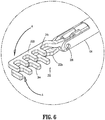
- the first and second jaws 202a, 202b are rotatable such that in an approximated configuration the first and second jaws 202a, 202b are approximately parallel as shown in FIG. 6 .
- First and second jaws 202a, 202b are pivotably connected to the end of elongate tubular shaft 104 by the pin 208 inserted through holes 210a, 210b at proximal ends of the first and second jaws 202a, 202b and openings 108 in the elongated tubular shaft 104.
- An actuation rod 212 includes opposed protrusions 214 that are positioned in first and second slots 216a, 216b that are located in proximal regions of the first and second jaws 202a, 202b, respectively, for transitioning the configuration of the first and second jaws 202a, 202b between the open configuration and the approximated configuration.
- First and second slots 216a, 216b may be positioned at acute angles relative to a longitudinal axis A-A of the first and second jaws 202a, 202b and the elongated tubular shaft 104, in reverse reflections of each other, such that, when the first and second jaws 202a, 202b are in the approximated configuration, the first and second slots 216a, 216b define an acute angle ⁇ when viewed from the side.
- the protrusions 214 of the actuation rod 212 are positioned in the slots 216a, 216b, such that, when the actuation rod 212 is translated in a distal direction, it slides the protrusions 214 distally in the slots 216a, 216b so as to transition the first and second jaws 202a, 202b from the open configuration to the approximated configuration. As the actuation rod 212 moves proximally, the protrusions 214 slide in the first and second slots 216a, 216b so as to transition the first and second jaws 202a, 202b to the open configuration from the approximated configuration.
- first and second jaws 202a, 202b may be actuated by a variety of mechanisms, as known in the art, for transitioning the first and second jaws 202a, 202b between an open configuration and a approximated configuration.
- first and second jaws 202a, 202b may be actuated by individual motors coupled to proximal ends of the first and second jaws 202a, 202b.
- the actuation rod 212 may be displaced between its proximal position and its distal position using the trigger 116 of the handle assembly 110 (see FIG. 1 ).
- the second jaw 202b may be constructed so that the first and second jaws 202a, 202b, when in the approximated position, align longitudinally on approximately the same plane.
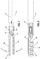
- the end effector 200 is shown in the open configuration in a top and side view, respectively.
- the first and second jaws 202a, 202b are sufficiently spaced apart so as to accept a section of tissue to be clamped and sutured.
- the actuation rod 212 is shown in phantom in FIG. 4 in a proximal position.
- the protrusions 214 of the actuation rod 212 are positioned in proximal ends of the first and second slots 216a, 216b, thereby maintaining the first and second jaws 202a, 202b in the open configuration.
- Pin 208 is shown coupling the first and second jaws 202a, 202b to each other at a distal end of the elongate tubular shaft 104.
- the first and second jaws may be pivotable from about zero degrees (Cf) to about one hundred and eighty degrees (180) about pin 208.
- first and second jaws 202a, 202b may define an acute angle.
- the end effector 200 is shown in the approximated configuration in perspective, top, and side views, respectively.
- Proximal ends of the first and second jaws 202a, 202b are laterally staggered and rotatable in parallel planes such that in the approximated configuration the first and second jaws 202a, 202b are approximately parallel.
- the first and second pluralities of teeth 204a, 204b of the first and second jaws 202a, 202b extend in the same direction from their respective jaws and are perpendicular to parallel planes when the end effector 200 is in the approximated configuration ( FIG. 7 ). As shown in FIGS.
- the second jaw 202b may extend farther in a distal direction than the first jaw 202a from the elongate tubular shaft 104.
- the first jaw 202a may extend farther in a distal direction than the second jaw 202b from the elongate tubular shaft 104.
- Actuation rod 212 is moved distally in the direction of arrow "B", sliding the protrusions 214 distally in slots 216a, 216b thereby causing the first and second jaws 202a, 202b to rotate in the direction of arrows "A" and into the approximated configuration ( FIGS. 6 and 7 ).
- first and second jaws 202a, 202b When the first and second jaws 202a, 202b are transitioned from the open configuration to the approximated configuration, the first and second jaws 202a, 202b clamp a section of tissue positioned between the first and second jaws 202a, 202b while the jaws were in the open configuration. Portions of the clamped tissue are displaced between the pluralities of teeth 204a, 204b when the end effector 200 is in the approximated configuration ( FIG. 10 ).
- the first jaw 202a may extend farther in a distal direction than the second jaw 202b such that each tooth 24a of the first plurality of teeth 204a is longitudinally offset from each tooth 24b of the second plurality of teeth 204b, thereby maximizing the amount of tissue displaced between the first and second pluralities of teeth 204a, 204b.
- either the first or second jaw 202a, 202b may extend farther in a distal direction so as to offset the first and second pluralities of teeth 204a, 204b to maximize tissue displacement when the end effector 200 is in the approximated configuration.
- first and second jaws 202a, 202b may extend an equal distance in a distal direction from the elongate tubular shaft 104, and the first and second pluralities of teeth 204a, 204b may be staggered along their respective first and second jaws 202a, 202b, such that one of the first or second pluralities of teeth 204a, 204b is offset from the other of the first or second pluralities of teeth 204a, 204b in order to maximize tissue displacement.
- a purse string suture 218 can be readily threaded through the tissue displaced between the first and second pluralities of teeth 204a, 204b (see FIG. 10 ).
- the first and second pluralities of teeth 204a, 204b may be variably offset longitudinally so as to maximize displacement of different types and/or sizes of tissues to be sutured.
- any number of teeth 24a, 24b may be disposed on the first and second jaws 202a, 202b so as to form the first and second pluralities of teeth 204a, 204b.
- the first plurality of teeth 204a may include four (4) teeth 24a sufficiently spaced apart so as to allow a sufficient section of colon to be displaced between the plurality of first teeth 204a to allow a suture to be run through the periphery of the tissue.
- the opposing second plurality of teeth 204b may include five (5) teeth 24b offset from the four (4) teeth 24a of the first plurality of teeth 204a in the example, also sufficiently spaced apart so as to allow sections of colon to be displaced between the first and second pluralities of teeth 204a, 204b, so as to place the purse string suture 218 about the entire periphery of displaced tissue through the end effector 200.
- Any suitable number of teeth 24a, 24b may be included in each of the first and second pluralities of teeth 204a, 204b for maximizing the amount of tissue displaced.
- the distance between each tooth 24a, 24b on the same jaw of the first and second pluralities of teeth 204a, 204b may be uniform or different.
- each tooth 24a, 24b on the same jaw of the first and second pluralities of teeth 204a, 204b may be sufficiently spaced apart such that a sufficient amount of tissue is displaced such that there is sufficient tissue to be sutured without tearing the tissue and/or there is sufficient tissue to hold the suture in place.
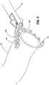
- the purse string suture instrument 100 of this disclosure is operatively shown in the open configuration about a section of tissue 220 and in the approximated configuration clamping the section of tissue 220, respectively.
- the section of tissue 220 to be sutured is positioned between the first and second jaws 202a, 202b in the open configuration ( FIG. 9 ).
- Actuating the trigger 116 of the handle assembly 110 ( FIG. 1 ) moves the actuation rod 212 distally so as to transition the first and second jaws 202a, 202b to the approximated configuration ( FIG. 10 ).
- tissue 220 is clamped and displaced outward between gaps in the longitudinally offset first and second pluralities of teeth 204a, 204b.
- a purse string suture 218 with a needle N may be placed through the displaced portions of the tissue 220 ( FIG. 10 ).
- displaced portions of tissue 220 extend through the first and second jaws 202a, 202b in a staggered arrangement.
- Sections of tissue 220 extending through the teeth 24a of the first plurality of teeth 204a of the first jaw 202a are longitudinally offset from sections of tissue 220 extending through the teeth 24b of the second plurality of teeth 204b of the second jaw 202b.
- the actuation rod 212 is moved to a proximal position, transitioning the end effector 200 from the approximated configuration ( FIG. 10 ) to the open configuration ( FIG. 9 ), thereby releasing the clamped and sutured tissue 220.
- the end effector 200 is then removed from around the section of tissue 220 so that a surgeon may continue a surgical procedure.
- the purse string suture 218 is cinched about the anvil shaft 234 of an EEA stapler, so the EEA stapler may be used to create an anastomosis.
- the anvil shaft 234 is part of an anvil assembly 230 that also includes an anvil 232.
- the anastomosis creates a passage between two sections of tissue, and the anvil 232 allows the EEA stapler to make that connection possible.
- the purse string suture 218 is threaded about the periphery of the hollow organ tissue 220.
- the end effector 200 FIG.
- the method for placing the purse string suture 218 includes first positioning the end effector 200 in an open configuration about a section of tissue 220 ( FIG.
- tissue 220 is clamped by the first and second jaws 202a, 202b of the end effector 200 in the approximated configuration, and portions of the tissue 220 are displaced through the longitudinally staggered first and second pluralities of teeth 204a, 204b on the first and second jaws 202a, 202b of the end effector 200.
- purse string suture 218 is threaded through the periphery of displaced portions of tissue 220.
- the actuation rod 212 is moved to a proximal position, transitioning the first and second jaws 202a, 202b of the end effector 200 from the approximated configuration to the open configuration thereby releasing the clamped section of tissue 220, and the end effector then removed from the tissue 220.
- the anvil 232 of an EEA stapler may be situated inside the section of tissue 220 before the purse string suture 218 is placed, or it may be inserted after the purse string suture 218 is threaded through the displaced tissue 220.
- the anvil 232 is positioned away from the first and second jaws 202a, 202b so as not to interfere with the end effector 200.
- the anvil 232 may be moved into position such that the purse string suture 218 can be cinched around the anvil shaft 234 of the EEA stapler in order to hold it in place, as shown in FIG. 11 , enabling the EEA stapler to readily engage the anvil 232 to create the anastomosis.
- the last step includes cinching the purse string suture 218 about the anvil shaft 234 and adjusting the purse string suture as desired, after which the surgeon may engage the anvil with the EEA stapler to create an anastomosis.
Landscapes
- Health & Medical Sciences (AREA)
- Life Sciences & Earth Sciences (AREA)
- Surgery (AREA)
- Heart & Thoracic Surgery (AREA)
- Engineering & Computer Science (AREA)
- Biomedical Technology (AREA)
- Nuclear Medicine, Radiotherapy & Molecular Imaging (AREA)
- Medical Informatics (AREA)
- Molecular Biology (AREA)
- Animal Behavior & Ethology (AREA)
- General Health & Medical Sciences (AREA)
- Public Health (AREA)
- Veterinary Medicine (AREA)
- Surgical Instruments (AREA)
Abstract
Description
- The present disclosure is generally related to surgical instruments. More particularly, the present disclosure relates to a purse string suture instrument for placing a purse string during an anastomosis procedure.
- Anastomosis is the surgical joining of separate hollow organ sections to allow the sections to communicate with each other. Typically, an anastomosis procedure follows surgery in which a diseased or defective section of hollow tissue is removed and the remaining end sections are to be joined. Depending on the desired anastomosis procedure, the end sections of the hollow organ may be joined using circular, end-to-end, end-to-side, or side-to-side organ reconstruction methods.
- In a circular anastomosis procedure, the two ends of the organ sections are joined by means of a surgical stapling instrument which drives a circular array of staples through the organ end sections and cores and removes any overlapping tissue to free a tubular passage. In some applications of a circular anastomosis procedure, an anvil rod having an attached anvil head is mounted to the distal end of a surgical stapling instrument shaft prior to insertion of the instrument into the tissue to be anastomosed. However, in other applications, a detachable anvil rod may be mounted to the instrument subsequent to positioning of the surgical stapling instrument and the anvil assembly within respective tissue sections. In such instances, the surgical stapling instrument and the anvil assembly are separately delivered to the operative site. Each tissue end section is then secured to a respective anvil or staple holding component, e.g., by a purse string suture. The anvil assembly is mounted to the surgical stapling instrument by inserting a mounting portion of the anvil rod within the distal end of the surgical stapling instrument so that a mounting mechanism within the surgical stapling instrument securely engages the anvil rod. Preparation of the tissue sections to be joined and mounting of the anvil rod to the surgical stapling instrument may be performed using minimally invasive surgical techniques, i.e., under laparoscopic guidance.
- The techniques of this disclosure generally relate to an end effector for a surgical device. The end effector includes first and second jaws disposed at a distal portion of an elongate tubular shaft, the first and second jaws pivotably coupled to each other at ends of the first and second jaws that are proximal to the elongate tubular shaft, the first and second jaws spaced apart and defining a gap therebetween. First and second pluralities of teeth extend perpendicularly from the first and second jaws respectively, and the first plurality of teeth is longitudinally offset from the second plurality of teeth. The first and second jaws are transitionable from an open configuration to an approximated configuration. The approximated configuration is adapted to clamp tissue in the gap between the first and second jaws and thereby displacing sections of tissue outwardly between the first and second pluralities of teeth.
- In aspects, the ends proximal to the elongate tubular shaft of the first and second jaws of the end effector may be laterally staggered and rotatable in parallel planes, such that in an approximated configuration the first and second jaws are approximately parallel.
- In other aspects, the first and second pluralities of teeth may extend in the same direction from their respective jaws and are perpendicular to parallel planes.
- In yet another aspect, the first jaw may extend distally farther from the elongate tubular shaft than the second jaw.
- In aspects, a proximal portion of the elongate tubular shaft may be adapted to couple with an actuation mechanism.
- In another aspect, the actuation mechanism may be configured to transition the first and second jaws between the open and approximated configurations.
- In aspects, the teeth of the first plurality of teeth of the first jaw are longitudinally spaced from the teeth of the second plurality of teeth of the second jaw.
- A method of suturing tissue includes positioning first and second jaws in an open configuration around tissue to be sutured. The first and second jaws being pivotably coupled to each other and spaced apart defining a gap therebetween. The first and second jaws have respective first and second pluralities of teeth extending perpendicularly therefrom wherein the first plurality of teeth are longitudinally offset from the second plurality of teeth and the first and second jaws extend distally from an elongate tubular shaft. Additionally, the method includes transitioning the first and second jaws from the open configuration to an approximated configuration so as to clamp tissue in the gap between the first and second jaws. The method also includes displacing sections of the clamped tissue outwardly between the first and second pluralities of teeth and then placing a suture through the displaced sections of the clamped tissue. The method also includes releasing the clamped tissue by returning the first and second jaws to the open configuration.
- In aspects, transitioning the first and second jaws from the open configuration to the approximated configuration may include laterally staggering the ends of the first and second jaws proximal to the elongate tubular shaft, the ends of the of the first and second jaws also rotatable in parallel planes, such that in the approximated configuration the first and second jaws are approximately parallel.
- In other aspects, displacing sections of the clamped tissue outwardly between the first and second pluralities of teeth may include the first and second pluralities of teeth of the first and second jaws extending in the same direction from their respective jaws and perpendicularly to parallel planes.
- In yet other aspects, transitioning the first and second jaws from the open configuration to the approximated configuration may include the first jaw extending distally farther from the elongate tubular shaft than the second jaw.
- In aspects, the method may include cinching the purse string suture about an anvil of a circular surgical stapler placed inside the section of tissue thereby fixating the anvil inside the section of tissue that was sutured.
- The details of one or more aspects of the disclosure are set forth in the accompanying drawings and the description below. Other features, objects, and advantages of the techniques described in this disclosure will be apparent from the description and drawings, and from the claims.
- The accompanying drawings, which are incorporated in and constitute a part of this specification, illustrate aspects and features of the disclosure and, together with the detailed description below, serve to further explain the disclosure, in which:
-
FIG. 1 is a perspective view of a purse string suture instrument including an end effector with first and second jaws; -
FIG. 2 is an enlarged view of the area of detail identified inFIG. 1 ; -
FIG. 3 is an exploded perspective view, with parts separated, of the end effector ofFIG. 2 ; -
FIG. 4 is a top view of the end effector ofFIG. 2 with the first and second jaws in an open configuration and an actuation rod shown in phantom; -
FIG. 5 is a side view of the end effector ofFIG. 2 with the first and second jaws in the open configuration; -
FIG. 6 is a perspective view of the end effector ofFIG. 2 with the first and second jaws in an approximated configuration; -
FIG. 7 is a top view of the end effector ofFIG. 2 with the first and second jaws in the approximated configuration and the actuation rod shown in phantom; -
FIG. 8 is a side view of the end effector ofFIG. 2 with the first and second jaws in the approximated position; -
FIG. 9 is a perspective view of the end effector ofFIG.2 with the first and second jaws in the open configuration and positioned about a section of tissue to be sutured; -
FIG. 10 is a top view of the end effector ofFIG. 9 in the approximated configuration clamping a section of tissue and a purse string suture; and -
FIG. 11 is an end perspective view of a tubular organ with a purse string suture applied thereto and an anvil assembly shown partially in phantom. - Further details and various aspects of this disclosure are described in more detail below with reference to the appended figures.
- Aspects of the presently disclosed purse string suture instrument are described in detail with reference to the drawings, in which like reference numerals designate identical or corresponding elements in each of the several views. However, it is to be understood that the disclosed devices are merely exemplary of the disclosure and may be embodied in various forms. Well-known functions or constructions are not described in detail to avoid obscuring the disclosure in unnecessary detail. Therefore, specific structural and functional details disclosed herein are not to be interpreted as limiting, but merely as a basis for the claims and as a representative basis for teaching one skilled in the art to variously employ the disclosure in virtually any appropriately detailed structure.
- Descriptions of technical features of an illustrative purse string suture instrument in accordance with the disclosure should typically be considered as available and applicable to other similar features of another device of the disclosure. Accordingly, technical features described herein in connection with one illustrative purse string suture instrument may be applicable to other devices of the disclosure, and thus duplicative descriptions may be omitted herein.
- As used herein the term "distal" refers to that portion of the surgical instrument, or component thereof, farther from the user, while the term "proximal" refers to that portion of the surgical instrument, or component thereof, closer to the user.
- The term "approximated configuration" refers to a configuration where the jaws of the end effector of the purse string suture instrument are in an approximately parallel configuration so as to clamp a section of tissue.
- Referring to
FIG. 1 , a pursestring suture instrument 100 including anend effector 200 with afirst jaw 202a, asecond jaw 202b, and an actuation mechanism orhandle assembly 110 is shown. During anterior resections, it is necessary to place a purse string suture about the periphery of a section of tissue in order to fixate an anvil of a circular stapler, such as an end to end anastomosis stapler (EEA stapler), in a section of colon to make the final staple joint with the EEA stapler similar to that described inU.S. Patent No. 6,945,444 , the entire contents of which are herein incorporated by reference. Theend effector 200 is at a distal end of an elongatedtubular shaft 104 attached to handleassembly 110 at its proximal end. Thehandle assembly 110 includes abody 112, astationary handle 114, atrigger 116, and acollar 118 for coupling the elongatedtubular shaft 104 to thehandle assembly 110. Theend effector 200 is configured to receive and clamp a section of tissue. In aspects, the tissue is a hollow organ tissue. Theend effector 200 may be operated manually by pivoting thetrigger 116 of thehandle assembly 110 towards thestationary handle 114. Alternatively, a robotic actuation mechanism (not shown) may be employed to actuate theend effector 200. In various aspects, the robotic actuation mechanism may be controlled by a surgeon via a computing device in electrical communication with the actuation mechanism. Theend effector 200 may be operated by a computing device, server, and/or network (not shown), which may include memory, storage device(s), controllers (e.g. software) for operating the end effector. - Referring additionally to
FIG. 2 , theend effector 200 with first andsecond jaws first jaw 202a and thesecond jaw 202b are connected at their proximal ends and connected to a distal end of the elongatetubular shaft 104. The first andsecond jaws pin 208. The first andsecond jaws second jaws second jaws FIG. 6 ). The handle assembly 110 (shown inFIG. 1 ) controls the position of the first andsecond jaws end effector 200 from the open configuration to the approximated configuration and vice versa. Thefirst jaw 202a may extend farther in a distal direction than thesecond jaw 202b from the elongatetubular shaft 104 as seen inFIG. 5 . Thefirst jaw 202a and thesecond jaw 202b include first and second pluralities ofteeth teeth 204a includesteeth 24a and the second plurality ofteeth 204b includesteeth 24b. Thefirst jaw 202a may extend farther in a distal direction than thesecond jaw 202b such that the first plurality ofteeth 204a is longitudinally offset from the second plurality ofteeth 204b as seen inFIG. 5 . The first andsecond jaws second jaws second jaws FIG. 6 . - With reference to
FIG. 3 , a perspective view of theend effector 200 with its various components separated is shown. First andsecond jaws tubular shaft 104 by thepin 208 inserted throughholes second jaws openings 108 in the elongatedtubular shaft 104. Anactuation rod 212 includes opposedprotrusions 214 that are positioned in first andsecond slots second jaws second jaws second slots second jaws tubular shaft 104, in reverse reflections of each other, such that, when the first andsecond jaws second slots protrusions 214 of theactuation rod 212 are positioned in theslots actuation rod 212 is translated in a distal direction, it slides theprotrusions 214 distally in theslots second jaws actuation rod 212 moves proximally, theprotrusions 214 slide in the first andsecond slots second jaws second jaws second jaws second jaws second jaws actuation rod 212 may be displaced between its proximal position and its distal position using thetrigger 116 of the handle assembly 110 (seeFIG. 1 ). Thesecond jaw 202b may be constructed so that the first andsecond jaws - Referring to
FIGS. 4 and 5 , theend effector 200 is shown in the open configuration in a top and side view, respectively. In the open configuration the first andsecond jaws actuation rod 212 is shown in phantom inFIG. 4 in a proximal position. Theprotrusions 214 of theactuation rod 212 are positioned in proximal ends of the first andsecond slots second jaws Pin 208 is shown coupling the first andsecond jaws tubular shaft 104. In aspects, the first and second jaws may be pivotable from about zero degrees (Cf) to about one hundred and eighty degrees (180) aboutpin 208. In the open configuration, first andsecond jaws - Referring to
FIGS. 6 ,7, and 8 , theend effector 200 is shown in the approximated configuration in perspective, top, and side views, respectively. Proximal ends of the first andsecond jaws second jaws teeth second jaws end effector 200 is in the approximated configuration (FIG. 7 ). As shown inFIGS. 7 and 8 , thesecond jaw 202b may extend farther in a distal direction than thefirst jaw 202a from the elongatetubular shaft 104. In aspects, thefirst jaw 202a may extend farther in a distal direction than thesecond jaw 202b from the elongatetubular shaft 104.Actuation rod 212 is moved distally in the direction of arrow "B", sliding theprotrusions 214 distally inslots second jaws FIGS. 6 and7 ). When the first andsecond jaws second jaws second jaws teeth end effector 200 is in the approximated configuration (FIG. 10 ). Thefirst jaw 202a may extend farther in a distal direction than thesecond jaw 202b such that eachtooth 24a of the first plurality ofteeth 204a is longitudinally offset from eachtooth 24b of the second plurality ofteeth 204b, thereby maximizing the amount of tissue displaced between the first and second pluralities ofteeth second jaw teeth end effector 200 is in the approximated configuration. In other aspects, the first andsecond jaws tubular shaft 104, and the first and second pluralities ofteeth second jaws teeth teeth purse string suture 218 can be readily threaded through the tissue displaced between the first and second pluralities ofteeth FIG. 10 ). The first and second pluralities ofteeth teeth second jaws teeth teeth 204a may include four (4)teeth 24a sufficiently spaced apart so as to allow a sufficient section of colon to be displaced between the plurality offirst teeth 204a to allow a suture to be run through the periphery of the tissue. The opposing second plurality ofteeth 204b may include five (5)teeth 24b offset from the four (4)teeth 24a of the first plurality ofteeth 204a in the example, also sufficiently spaced apart so as to allow sections of colon to be displaced between the first and second pluralities ofteeth purse string suture 218 about the entire periphery of displaced tissue through theend effector 200. Any suitable number ofteeth 24a, 24bmay be included in each of the first and second pluralities ofteeth tooth teeth tooth teeth - Referring to
FIGS. 9 and10 , the pursestring suture instrument 100 of this disclosure is operatively shown in the open configuration about a section oftissue 220 and in the approximated configuration clamping the section oftissue 220, respectively. The section oftissue 220 to be sutured is positioned between the first andsecond jaws FIG. 9 ). Actuating thetrigger 116 of the handle assembly 110 (FIG. 1 ) moves theactuation rod 212 distally so as to transition the first andsecond jaws FIG. 10 ). As the first andsecond jaws tissue 220 is clamped and displaced outward between gaps in the longitudinally offset first and second pluralities ofteeth tissue 220 is clamped and portions of thetissue 220 sufficiently displaced outward between the first and second pluralities ofteeth purse string suture 218 with a needle N may be placed through the displaced portions of the tissue 220 (FIG. 10 ). In particular, displaced portions oftissue 220 extend through the first andsecond jaws tissue 220 extending through theteeth 24a of the first plurality ofteeth 204a of thefirst jaw 202a are longitudinally offset from sections oftissue 220 extending through theteeth 24b of the second plurality ofteeth 204b of thesecond jaw 202b. After thepurse string suture 218 is placed through thetissue 220, theactuation rod 212 is moved to a proximal position, transitioning theend effector 200 from the approximated configuration (FIG. 10 ) to the open configuration (FIG. 9 ), thereby releasing the clamped and suturedtissue 220. Theend effector 200 is then removed from around the section oftissue 220 so that a surgeon may continue a surgical procedure. - With reference to
FIG. 11 , thepurse string suture 218 is cinched about theanvil shaft 234 of an EEA stapler, so the EEA stapler may be used to create an anastomosis. Theanvil shaft 234 is part of ananvil assembly 230 that also includes ananvil 232. The anastomosis creates a passage between two sections of tissue, and theanvil 232 allows the EEA stapler to make that connection possible. Before theanvil 232 is positioned by the surgeon in the section oftissue 220 to be used for the anastomosis, thepurse string suture 218 is threaded about the periphery of thehollow organ tissue 220. The end effector 200 (FIG. 1 ) facilitates placement of thepurse string suture 218 by clamping the section oftissue 220 to be fixated around theanvil 232 of the EEA stapler, displacing as much of thetissue 220 as desired through first and second pluralities ofteeth FIG. 10 ) disposed on the first andsecond jaws end effector 200, and then threading thepurse string suture 218 and needle N through the displacedtissue 220. The method for placing thepurse string suture 218 includes first positioning theend effector 200 in an open configuration about a section of tissue 220 (FIG. 9 ), and then actuationrod 212 is moved to a distalposition causing protrusions 214 to slide distally inslots end effector 200 from the open configuration to the approximated configuration. At the next step, thetissue 220 is clamped by the first andsecond jaws end effector 200 in the approximated configuration, and portions of thetissue 220 are displaced through the longitudinally staggered first and second pluralities ofteeth second jaws end effector 200. Thereafter, thepurse string suture 218 is threaded through the periphery of displaced portions oftissue 220. After thepurse string suture 218 is placed, theactuation rod 212 is moved to a proximal position, transitioning the first andsecond jaws end effector 200 from the approximated configuration to the open configuration thereby releasing the clamped section oftissue 220, and the end effector then removed from thetissue 220. Theanvil 232 of an EEA stapler may be situated inside the section oftissue 220 before thepurse string suture 218 is placed, or it may be inserted after thepurse string suture 218 is threaded through the displacedtissue 220. In the former situation, before theend effector 200 is positioned about a section oftissue 220, theanvil 232 is positioned away from the first andsecond jaws end effector 200. In either situation, after thepurse string suture 218 is placed and the end effector is removed, theanvil 232 may be moved into position such that thepurse string suture 218 can be cinched around theanvil shaft 234 of the EEA stapler in order to hold it in place, as shown inFIG. 11 , enabling the EEA stapler to readily engage theanvil 232 to create the anastomosis. The last step includes cinching thepurse string suture 218 about theanvil shaft 234 and adjusting the purse string suture as desired, after which the surgeon may engage the anvil with the EEA stapler to create an anastomosis. - It should be understood that various aspects disclosed herein may be combined in different combinations than the combinations specifically presented in the description and accompanying drawings. It should also be understood that, depending on the example, certain acts or events of any of the processes or methods described herein may be performed in a different sequence, may be added, merged, or left out altogether (e.g., all described acts or events may not be necessary to carry out the techniques). In addition, while certain aspects of this disclosure are described as being performed by a single module or unit for purposes of clarity, it should be understood that the techniques of this disclosure may be performed by a combination of units or modules associated with, for example, a medical device.
- The invention may be described by reference to the following numbered paragraphs:-
- 1. An end effector for a surgical device comprising:
- first and second jaws disposed at a distal portion of an elongate tubular shaft, the first and second jaws pivotably coupled to each other at ends of the first and second jaws that are proximal to the elongate tubular shaft, the first and second jaws spaced apart and defining a gap therebetween; and
- first and second pluralities of teeth extending perpendicularly from the first and second jaws respectively, the first plurality of teeth longitudinally offset from the second plurality of teeth;
- 2. The end effector of paragraph 1, wherein the ends proximal to the elongate tubular shaft of the first and second jaws are laterally staggered and rotatable in parallel planes, such that in an approximated configuration the first and second jaws are approximately parallel.
- 3. The end effector of
paragraph 2, wherein the first and second pluralities of teeth extend in the same direction from their respective jaws and perpendicular to parallel planes. - 4. The end effector of paragraph 1, wherein the first jaw extends distally farther from the elongate tubular shaft than the second jaw.
- 5. The end effector of paragraph 1, wherein a proximal portion of the elongate tubular shaft is adapted to couple with an actuation mechanism.
- 6. The end effector of paragraph 5, wherein the actuation mechanism is configured to transition the first and second jaws between the open and approximated configurations.
- 7. The end effector of paragraph 1, wherein the teeth of the first plurality of teeth of the first jaw are longitudinally spaced from the teeth of the second plurality of teeth of the second jaw.
- 8. A method of suturing tissue comprising:
- positioning first and second jaws in an open configuration around tissue to be sutured, the first and second jaws pivotably coupled to each other and spaced apart defining a gap therebetween, the first and second jaws having respective first and second pluralities of teeth extending perpendicularly therefrom, the first plurality of teeth longitudinally offset from the second plurality of teeth, the first and second jaws extending distally from an elongate tubular shaft;
- transitioning the first and second jaws from the open configuration to an approximated configuration so as to clamp tissue in the gap between the first and second jaws;
- displacing sections of the clamped tissue outwardly between the first and second pluralities of teeth;
- placing a suture through the displaced sections of the clamped tissue; and
- releasing the clamped tissue by returning the first and second jaws to the open configuration.
- 9. The method of paragraph 8, wherein transitioning the first and second jaws from the open configuration to the approximated configuration includes laterally staggering the ends of the first and second jaws proximal to the elongate tubular shaft, the ends of the of the first and second jaws also rotatable in parallel planes, such that in the approximated configuration the first and second jaws are approximately parallel.
- 10. The method of paragraph 8, wherein displacing sections of the clamped tissue outwardly between the first and second pluralities of teeth includes the first and second pluralities of teeth of the first and second jaws extending in the same direction from their respective jaws and perpendicularly to parallel planes.
- 11. The method of paragraph 8, wherein transitioning the first and second jaws from the open configuration to the approximated configuration includes the first jaw extending distally farther from the elongate tubular shaft than the second jaw.
- 12. The method of paragraph 8, further including cinching the purse string suture about an anvil of a circular surgical stapler placed inside the section of tissue thereby fixating the anvil inside the section of tissue that was sutured.
Claims (7)
- An end effector for a surgical device comprising:first and second jaws disposed at a distal portion of an elongate tubular shaft, the first and second jaws pivotably coupled to each other at ends of the first and second jaws that are proximal to the elongate tubular shaft, the first and second jaws spaced apart and defining a gap therebetween; andfirst and second pluralities of teeth extending perpendicularly from the first and second jaws respectively, the first plurality of teeth longitudinally offset from the second plurality of teeth;wherein the first and second jaws are transitionable from an open configuration to an approximated configuration, the approximated configuration adapted to clamp tissue in the gap between the first and second jaws and thereby displacing sections of tissue outwardly between the first and second pluralities of teeth.
- The end effector of claim 1, wherein the ends proximal to the elongate tubular shaft of the first and second jaws are laterally staggered and rotatable in parallel planes, such that in an approximated configuration the first and second jaws are approximately parallel.
- The end effector of claim 2, wherein the first and second pluralities of teeth extend in the same direction from their respective jaws and perpendicular to parallel planes.
- The end effector of any preceding claim, wherein the first jaw extends distally farther from the elongate tubular shaft than the second jaw.
- The end effector of any preceding claim, wherein a proximal portion of the elongate tubular shaft is adapted to couple with an actuation mechanism.
- The end effector of claim 5, wherein the actuation mechanism is configured to transition the first and second jaws between the open and approximated configurations.
- The end effector of any preceding claim, wherein the teeth of the first plurality of teeth of the first jaw are longitudinally spaced from the teeth of the second plurality of teeth of the second jaw.
Applications Claiming Priority (1)
| Application Number | Priority Date | Filing Date | Title |
|---|---|---|---|
| US16/923,850 US11666337B2 (en) | 2020-07-08 | 2020-07-08 | Purse string suture instrument |
Publications (2)
| Publication Number | Publication Date |
|---|---|
| EP3936060A1 true EP3936060A1 (en) | 2022-01-12 |
| EP3936060B1 EP3936060B1 (en) | 2023-12-27 |
Family
ID=76744771
Family Applications (1)
| Application Number | Title | Priority Date | Filing Date |
|---|---|---|---|
| EP21183279.5A Active EP3936060B1 (en) | 2020-07-08 | 2021-07-01 | Purse string suture instrument |
Country Status (2)
| Country | Link |
|---|---|
| US (1) | US11666337B2 (en) |
| EP (1) | EP3936060B1 (en) |
Families Citing this family (2)
| Publication number | Priority date | Publication date | Assignee | Title |
|---|---|---|---|---|
| LU101444B1 (en) * | 2019-10-15 | 2021-04-15 | G Hipp & Sohn Gmbh | Surgical instrument |
| LU102168B1 (en) * | 2020-10-26 | 2022-04-27 | G Hipp & Sohn Gmbh | surgical instrument |
Citations (4)
| Publication number | Priority date | Publication date | Assignee | Title |
|---|---|---|---|---|
| US4611592A (en) * | 1983-08-05 | 1986-09-16 | Talboy Glenn E | Clamp for holding surgical lines |
| US6945444B2 (en) | 2001-04-03 | 2005-09-20 | Tyco Healthcare Group, Lp | Surgical stapling device for performing circular anastomoses |
| US20090312602A1 (en) * | 2005-07-22 | 2009-12-17 | Yuji Sakamoto | Pressing member, endoscopic treatment system, and endoscopic suturing device |
| CN109431563A (en) * | 2018-12-03 | 2019-03-08 | 郑州大学第附属医院 | Hysteroscope purse-string forceps |
Family Cites Families (11)
| Publication number | Priority date | Publication date | Assignee | Title |
|---|---|---|---|---|
| US4226241A (en) * | 1979-06-26 | 1980-10-07 | Walker Jr William E | Surgical forceps |
| US4345600A (en) * | 1980-08-04 | 1982-08-24 | Senco Products, Inc. | Purse-stringer |
| US5411481A (en) | 1992-04-08 | 1995-05-02 | American Cyanamid Co. | Surgical purse string suturing instrument and method |
| EP0604789A1 (en) * | 1992-12-31 | 1994-07-06 | K. Widmann Ag | Surgical clamping element for making a purse string |
| US8092473B2 (en) | 1997-02-03 | 2012-01-10 | Applied Medical Resources Corporation | Surgical clamp with improved traction |
| US6607227B1 (en) * | 2000-06-28 | 2003-08-19 | Siemens Automotive Corporation | Sawtooth terminal blade gripper and method of gripping |
| US7322995B2 (en) | 2002-09-13 | 2008-01-29 | Damage Control Surgical Technologies, Inc. | Method and apparatus for vascular and visceral clipping |
| US20050267529A1 (en) | 2004-05-13 | 2005-12-01 | Heber Crockett | Devices, systems and methods for tissue repair |
| US8128642B2 (en) * | 2008-05-02 | 2012-03-06 | Tyco Healthcare Group Lp | Fluid delivery system for surgical instruments |
| US10646217B2 (en) * | 2018-05-04 | 2020-05-12 | Arch Day Design, Llc | Suture passing device |
| CN209734062U (en) | 2018-09-07 | 2019-12-06 | 石河子大学 | A double joint esophageal purse suture forceps |
-
2020
- 2020-07-08 US US16/923,850 patent/US11666337B2/en active Active
-
2021
- 2021-07-01 EP EP21183279.5A patent/EP3936060B1/en active Active
Patent Citations (4)
| Publication number | Priority date | Publication date | Assignee | Title |
|---|---|---|---|---|
| US4611592A (en) * | 1983-08-05 | 1986-09-16 | Talboy Glenn E | Clamp for holding surgical lines |
| US6945444B2 (en) | 2001-04-03 | 2005-09-20 | Tyco Healthcare Group, Lp | Surgical stapling device for performing circular anastomoses |
| US20090312602A1 (en) * | 2005-07-22 | 2009-12-17 | Yuji Sakamoto | Pressing member, endoscopic treatment system, and endoscopic suturing device |
| CN109431563A (en) * | 2018-12-03 | 2019-03-08 | 郑州大学第附属医院 | Hysteroscope purse-string forceps |
Also Published As
| Publication number | Publication date |
|---|---|
| US20220008072A1 (en) | 2022-01-13 |
| EP3936060B1 (en) | 2023-12-27 |
| US11666337B2 (en) | 2023-06-06 |
Similar Documents
| Publication | Publication Date | Title |
|---|---|---|
| CN112867447B (en) | Endoscopic purse-line suture surgical device | |
| JP4184085B2 (en) | Surgical grasping instrument | |
| US6468285B1 (en) | Surgical instruments and procedures | |
| US9125646B2 (en) | Needle for laparoscopic suturing instrument | |
| AU2002250207A1 (en) | Surgical grasping instrument | |
| US20050107807A1 (en) | Deep endoscopic staple and stapler | |
| EP2238919A2 (en) | Endoscopic apparatus for manipulating tissue | |
| US12290258B2 (en) | Stapler apparatus and methods for use | |
| CN115460995A (en) | Stapler apparatus and method of using same | |
| CN104434245B (en) | End effector, surgical operating instrument and purse-string forceps | |
| US20230056943A1 (en) | Stapler apparatus and methods for use | |
| EP3936060B1 (en) | Purse string suture instrument | |
| CN104434252B (en) | End effector, surgical operating instrument and purse-string forceps | |
| CN104434241A (en) | End effector, surgical operating instrument and purse-string forceps | |
| CN203564292U (en) | End effector, surgical operating instrument, purse-string forceps and purse-string nails | |
| US11779342B2 (en) | Laparoscopic purse string suture device | |
| US11672533B2 (en) | Laparoscopic transverse surgical stapling system | |
| EP1923009A2 (en) | Surgical grasping instrument | |
| CN222657103U (en) | Automatic purse-string suture forceps for laparoscope | |
| US20210322002A1 (en) | Surgical instrument for performing a purse string suture | |
| RU2802892C2 (en) | Flexible powered surgical instrument | |
| JPH01129844A (en) | Surgical sewing tool |
Legal Events
| Date | Code | Title | Description |
|---|---|---|---|
| PUAI | Public reference made under article 153(3) epc to a published international application that has entered the european phase |
Free format text: ORIGINAL CODE: 0009012 |
|
| STAA | Information on the status of an ep patent application or granted ep patent |
Free format text: STATUS: THE APPLICATION HAS BEEN PUBLISHED |
|
| AK | Designated contracting states |
Kind code of ref document: A1 Designated state(s): AL AT BE BG CH CY CZ DE DK EE ES FI FR GB GR HR HU IE IS IT LI LT LU LV MC MK MT NL NO PL PT RO RS SE SI SK SM TR |
|
| B565 | Issuance of search results under rule 164(2) epc |
Effective date: 20211103 |
|
| STAA | Information on the status of an ep patent application or granted ep patent |
Free format text: STATUS: REQUEST FOR EXAMINATION WAS MADE |
|
| 17P | Request for examination filed |
Effective date: 20220630 |
|
| RBV | Designated contracting states (corrected) |
Designated state(s): AL AT BE BG CH CY CZ DE DK EE ES FI FR GB GR HR HU IE IS IT LI LT LU LV MC MK MT NL NO PL PT RO RS SE SI SK SM TR |
|
| STAA | Information on the status of an ep patent application or granted ep patent |
Free format text: STATUS: EXAMINATION IS IN PROGRESS |
|
| 17Q | First examination report despatched |
Effective date: 20230119 |
|
| GRAP | Despatch of communication of intention to grant a patent |
Free format text: ORIGINAL CODE: EPIDOSNIGR1 |
|
| STAA | Information on the status of an ep patent application or granted ep patent |
Free format text: STATUS: GRANT OF PATENT IS INTENDED |
|
| INTG | Intention to grant announced |
Effective date: 20230725 |
|
| GRAS | Grant fee paid |
Free format text: ORIGINAL CODE: EPIDOSNIGR3 |
|
| GRAA | (expected) grant |
Free format text: ORIGINAL CODE: 0009210 |
|
| STAA | Information on the status of an ep patent application or granted ep patent |
Free format text: STATUS: THE PATENT HAS BEEN GRANTED |
|
| AK | Designated contracting states |
Kind code of ref document: B1 Designated state(s): AL AT BE BG CH CY CZ DE DK EE ES FI FR GB GR HR HU IE IS IT LI LT LU LV MC MK MT NL NO PL PT RO RS SE SI SK SM TR |
|
| REG | Reference to a national code |
Ref country code: GB Ref legal event code: FG4D |
|
| REG | Reference to a national code |
Ref country code: CH Ref legal event code: EP |
|
| REG | Reference to a national code |
Ref country code: DE Ref legal event code: R096 Ref document number: 602021008026 Country of ref document: DE |
|
| REG | Reference to a national code |
Ref country code: IE Ref legal event code: FG4D |
|
| PG25 | Lapsed in a contracting state [announced via postgrant information from national office to epo] |
Ref country code: GR Free format text: LAPSE BECAUSE OF FAILURE TO SUBMIT A TRANSLATION OF THE DESCRIPTION OR TO PAY THE FEE WITHIN THE PRESCRIBED TIME-LIMIT Effective date: 20240328 |
|
| REG | Reference to a national code |
Ref country code: LT Ref legal event code: MG9D |
|
| PG25 | Lapsed in a contracting state [announced via postgrant information from national office to epo] |
Ref country code: LT Free format text: LAPSE BECAUSE OF FAILURE TO SUBMIT A TRANSLATION OF THE DESCRIPTION OR TO PAY THE FEE WITHIN THE PRESCRIBED TIME-LIMIT Effective date: 20231227 |
|
| PG25 | Lapsed in a contracting state [announced via postgrant information from national office to epo] |
Ref country code: ES Free format text: LAPSE BECAUSE OF FAILURE TO SUBMIT A TRANSLATION OF THE DESCRIPTION OR TO PAY THE FEE WITHIN THE PRESCRIBED TIME-LIMIT Effective date: 20231227 |
|
| PG25 | Lapsed in a contracting state [announced via postgrant information from national office to epo] |
Ref country code: LT Free format text: LAPSE BECAUSE OF FAILURE TO SUBMIT A TRANSLATION OF THE DESCRIPTION OR TO PAY THE FEE WITHIN THE PRESCRIBED TIME-LIMIT Effective date: 20231227 Ref country code: GR Free format text: LAPSE BECAUSE OF FAILURE TO SUBMIT A TRANSLATION OF THE DESCRIPTION OR TO PAY THE FEE WITHIN THE PRESCRIBED TIME-LIMIT Effective date: 20240328 Ref country code: FI Free format text: LAPSE BECAUSE OF FAILURE TO SUBMIT A TRANSLATION OF THE DESCRIPTION OR TO PAY THE FEE WITHIN THE PRESCRIBED TIME-LIMIT Effective date: 20231227 Ref country code: ES Free format text: LAPSE BECAUSE OF FAILURE TO SUBMIT A TRANSLATION OF THE DESCRIPTION OR TO PAY THE FEE WITHIN THE PRESCRIBED TIME-LIMIT Effective date: 20231227 Ref country code: BG Free format text: LAPSE BECAUSE OF FAILURE TO SUBMIT A TRANSLATION OF THE DESCRIPTION OR TO PAY THE FEE WITHIN THE PRESCRIBED TIME-LIMIT Effective date: 20240327 |
|
| REG | Reference to a national code |
Ref country code: NL Ref legal event code: MP Effective date: 20231227 |
|
| REG | Reference to a national code |
Ref country code: AT Ref legal event code: MK05 Ref document number: 1643784 Country of ref document: AT Kind code of ref document: T Effective date: 20231227 |
|
| PG25 | Lapsed in a contracting state [announced via postgrant information from national office to epo] |
Ref country code: NL Free format text: LAPSE BECAUSE OF FAILURE TO SUBMIT A TRANSLATION OF THE DESCRIPTION OR TO PAY THE FEE WITHIN THE PRESCRIBED TIME-LIMIT Effective date: 20231227 |
|
| PG25 | Lapsed in a contracting state [announced via postgrant information from national office to epo] |
Ref country code: SE Free format text: LAPSE BECAUSE OF FAILURE TO SUBMIT A TRANSLATION OF THE DESCRIPTION OR TO PAY THE FEE WITHIN THE PRESCRIBED TIME-LIMIT Effective date: 20231227 Ref country code: RS Free format text: LAPSE BECAUSE OF FAILURE TO SUBMIT A TRANSLATION OF THE DESCRIPTION OR TO PAY THE FEE WITHIN THE PRESCRIBED TIME-LIMIT Effective date: 20231227 Ref country code: NO Free format text: LAPSE BECAUSE OF FAILURE TO SUBMIT A TRANSLATION OF THE DESCRIPTION OR TO PAY THE FEE WITHIN THE PRESCRIBED TIME-LIMIT Effective date: 20240327 Ref country code: NL Free format text: LAPSE BECAUSE OF FAILURE TO SUBMIT A TRANSLATION OF THE DESCRIPTION OR TO PAY THE FEE WITHIN THE PRESCRIBED TIME-LIMIT Effective date: 20231227 Ref country code: LV Free format text: LAPSE BECAUSE OF FAILURE TO SUBMIT A TRANSLATION OF THE DESCRIPTION OR TO PAY THE FEE WITHIN THE PRESCRIBED TIME-LIMIT Effective date: 20231227 Ref country code: HR Free format text: LAPSE BECAUSE OF FAILURE TO SUBMIT A TRANSLATION OF THE DESCRIPTION OR TO PAY THE FEE WITHIN THE PRESCRIBED TIME-LIMIT Effective date: 20231227 |
|
| PG25 | Lapsed in a contracting state [announced via postgrant information from national office to epo] |
Ref country code: IS Free format text: LAPSE BECAUSE OF FAILURE TO SUBMIT A TRANSLATION OF THE DESCRIPTION OR TO PAY THE FEE WITHIN THE PRESCRIBED TIME-LIMIT Effective date: 20240427 |
|
| PG25 | Lapsed in a contracting state [announced via postgrant information from national office to epo] |
Ref country code: CZ Free format text: LAPSE BECAUSE OF FAILURE TO SUBMIT A TRANSLATION OF THE DESCRIPTION OR TO PAY THE FEE WITHIN THE PRESCRIBED TIME-LIMIT Effective date: 20231227 Ref country code: AT Free format text: LAPSE BECAUSE OF FAILURE TO SUBMIT A TRANSLATION OF THE DESCRIPTION OR TO PAY THE FEE WITHIN THE PRESCRIBED TIME-LIMIT Effective date: 20231227 |
|
| PG25 | Lapsed in a contracting state [announced via postgrant information from national office to epo] |
Ref country code: SK Free format text: LAPSE BECAUSE OF FAILURE TO SUBMIT A TRANSLATION OF THE DESCRIPTION OR TO PAY THE FEE WITHIN THE PRESCRIBED TIME-LIMIT Effective date: 20231227 |
|
| PG25 | Lapsed in a contracting state [announced via postgrant information from national office to epo] |
Ref country code: SM Free format text: LAPSE BECAUSE OF FAILURE TO SUBMIT A TRANSLATION OF THE DESCRIPTION OR TO PAY THE FEE WITHIN THE PRESCRIBED TIME-LIMIT Effective date: 20231227 Ref country code: SK Free format text: LAPSE BECAUSE OF FAILURE TO SUBMIT A TRANSLATION OF THE DESCRIPTION OR TO PAY THE FEE WITHIN THE PRESCRIBED TIME-LIMIT Effective date: 20231227 Ref country code: RO Free format text: LAPSE BECAUSE OF FAILURE TO SUBMIT A TRANSLATION OF THE DESCRIPTION OR TO PAY THE FEE WITHIN THE PRESCRIBED TIME-LIMIT Effective date: 20231227 Ref country code: IT Free format text: LAPSE BECAUSE OF FAILURE TO SUBMIT A TRANSLATION OF THE DESCRIPTION OR TO PAY THE FEE WITHIN THE PRESCRIBED TIME-LIMIT Effective date: 20231227 Ref country code: IS Free format text: LAPSE BECAUSE OF FAILURE TO SUBMIT A TRANSLATION OF THE DESCRIPTION OR TO PAY THE FEE WITHIN THE PRESCRIBED TIME-LIMIT Effective date: 20240427 Ref country code: EE Free format text: LAPSE BECAUSE OF FAILURE TO SUBMIT A TRANSLATION OF THE DESCRIPTION OR TO PAY THE FEE WITHIN THE PRESCRIBED TIME-LIMIT Effective date: 20231227 Ref country code: CZ Free format text: LAPSE BECAUSE OF FAILURE TO SUBMIT A TRANSLATION OF THE DESCRIPTION OR TO PAY THE FEE WITHIN THE PRESCRIBED TIME-LIMIT Effective date: 20231227 Ref country code: AT Free format text: LAPSE BECAUSE OF FAILURE TO SUBMIT A TRANSLATION OF THE DESCRIPTION OR TO PAY THE FEE WITHIN THE PRESCRIBED TIME-LIMIT Effective date: 20231227 |
|
| PG25 | Lapsed in a contracting state [announced via postgrant information from national office to epo] |
Ref country code: PT Free format text: LAPSE BECAUSE OF FAILURE TO SUBMIT A TRANSLATION OF THE DESCRIPTION OR TO PAY THE FEE WITHIN THE PRESCRIBED TIME-LIMIT Effective date: 20240429 Ref country code: PL Free format text: LAPSE BECAUSE OF FAILURE TO SUBMIT A TRANSLATION OF THE DESCRIPTION OR TO PAY THE FEE WITHIN THE PRESCRIBED TIME-LIMIT Effective date: 20231227 |
|
| PG25 | Lapsed in a contracting state [announced via postgrant information from national office to epo] |
Ref country code: PT Free format text: LAPSE BECAUSE OF FAILURE TO SUBMIT A TRANSLATION OF THE DESCRIPTION OR TO PAY THE FEE WITHIN THE PRESCRIBED TIME-LIMIT Effective date: 20240429 Ref country code: PL Free format text: LAPSE BECAUSE OF FAILURE TO SUBMIT A TRANSLATION OF THE DESCRIPTION OR TO PAY THE FEE WITHIN THE PRESCRIBED TIME-LIMIT Effective date: 20231227 |
|
| REG | Reference to a national code |
Ref country code: DE Ref legal event code: R097 Ref document number: 602021008026 Country of ref document: DE |
|
| PG25 | Lapsed in a contracting state [announced via postgrant information from national office to epo] |
Ref country code: DK Free format text: LAPSE BECAUSE OF FAILURE TO SUBMIT A TRANSLATION OF THE DESCRIPTION OR TO PAY THE FEE WITHIN THE PRESCRIBED TIME-LIMIT Effective date: 20231227 |
|
| PG25 | Lapsed in a contracting state [announced via postgrant information from national office to epo] |
Ref country code: DK Free format text: LAPSE BECAUSE OF FAILURE TO SUBMIT A TRANSLATION OF THE DESCRIPTION OR TO PAY THE FEE WITHIN THE PRESCRIBED TIME-LIMIT Effective date: 20231227 |
|
| PLBE | No opposition filed within time limit |
Free format text: ORIGINAL CODE: 0009261 |
|
| STAA | Information on the status of an ep patent application or granted ep patent |
Free format text: STATUS: NO OPPOSITION FILED WITHIN TIME LIMIT |
|
| 26N | No opposition filed |
Effective date: 20240930 |
|
| REG | Reference to a national code |
Ref country code: DE Ref legal event code: R119 Ref document number: 602021008026 Country of ref document: DE |
|
| PG25 | Lapsed in a contracting state [announced via postgrant information from national office to epo] |
Ref country code: MC Free format text: LAPSE BECAUSE OF FAILURE TO SUBMIT A TRANSLATION OF THE DESCRIPTION OR TO PAY THE FEE WITHIN THE PRESCRIBED TIME-LIMIT Effective date: 20231227 |
|
| REG | Reference to a national code |
Ref country code: CH Ref legal event code: PL |
|
| PG25 | Lapsed in a contracting state [announced via postgrant information from national office to epo] |
Ref country code: LU Free format text: LAPSE BECAUSE OF NON-PAYMENT OF DUE FEES Effective date: 20240701 |
|
| PG25 | Lapsed in a contracting state [announced via postgrant information from national office to epo] |
Ref country code: LU Free format text: LAPSE BECAUSE OF NON-PAYMENT OF DUE FEES Effective date: 20240701 |
|
| PG25 | Lapsed in a contracting state [announced via postgrant information from national office to epo] |
Ref country code: DE Free format text: LAPSE BECAUSE OF NON-PAYMENT OF DUE FEES Effective date: 20250201 |
|
| PG25 | Lapsed in a contracting state [announced via postgrant information from national office to epo] |
Ref country code: CH Free format text: LAPSE BECAUSE OF NON-PAYMENT OF DUE FEES Effective date: 20240731 Ref country code: SI Free format text: LAPSE BECAUSE OF FAILURE TO SUBMIT A TRANSLATION OF THE DESCRIPTION OR TO PAY THE FEE WITHIN THE PRESCRIBED TIME-LIMIT Effective date: 20231227 Ref country code: BE Free format text: LAPSE BECAUSE OF NON-PAYMENT OF DUE FEES Effective date: 20240731 |
|
| PG25 | Lapsed in a contracting state [announced via postgrant information from national office to epo] |
Ref country code: FR Free format text: LAPSE BECAUSE OF NON-PAYMENT OF DUE FEES Effective date: 20240731 |
|
| REG | Reference to a national code |
Ref country code: BE Ref legal event code: MM Effective date: 20240731 |
|
| PG25 | Lapsed in a contracting state [announced via postgrant information from national office to epo] |
Ref country code: IE Free format text: LAPSE BECAUSE OF NON-PAYMENT OF DUE FEES Effective date: 20240701 |
|
| PG25 | Lapsed in a contracting state [announced via postgrant information from national office to epo] |
Ref country code: CY Free format text: LAPSE BECAUSE OF FAILURE TO SUBMIT A TRANSLATION OF THE DESCRIPTION OR TO PAY THE FEE WITHIN THE PRESCRIBED TIME-LIMIT; INVALID AB INITIO Effective date: 20210701 |
|
| PG25 | Lapsed in a contracting state [announced via postgrant information from national office to epo] |
Ref country code: HU Free format text: LAPSE BECAUSE OF FAILURE TO SUBMIT A TRANSLATION OF THE DESCRIPTION OR TO PAY THE FEE WITHIN THE PRESCRIBED TIME-LIMIT; INVALID AB INITIO Effective date: 20210701 |
|
| GBPC | Gb: european patent ceased through non-payment of renewal fee |
Effective date: 20250701 |
|
| PG25 | Lapsed in a contracting state [announced via postgrant information from national office to epo] |
Ref country code: GB Free format text: LAPSE BECAUSE OF NON-PAYMENT OF DUE FEES Effective date: 20250701 |