EP3936008B1 - Temperature measuring and overflow preventing probe for pot - Google Patents
Temperature measuring and overflow preventing probe for pot Download PDFInfo
- Publication number
- EP3936008B1 EP3936008B1 EP21183364.5A EP21183364A EP3936008B1 EP 3936008 B1 EP3936008 B1 EP 3936008B1 EP 21183364 A EP21183364 A EP 21183364A EP 3936008 B1 EP3936008 B1 EP 3936008B1
- Authority
- EP
- European Patent Office
- Prior art keywords
- overflow
- probe
- pot
- temperature measuring
- detecting part
- Prior art date
- Legal status (The legal status is an assumption and is not a legal conclusion. Google has not performed a legal analysis and makes no representation as to the accuracy of the status listed.)
- Active
Links
Images



Classifications
-
- A—HUMAN NECESSITIES
- A47—FURNITURE; DOMESTIC ARTICLES OR APPLIANCES; COFFEE MILLS; SPICE MILLS; SUCTION CLEANERS IN GENERAL
- A47J—KITCHEN EQUIPMENT; COFFEE MILLS; SPICE MILLS; APPARATUS FOR MAKING BEVERAGES
- A47J27/00—Cooking-vessels
- A47J27/56—Preventing boiling over, e.g. of milk
- A47J27/62—Preventing boiling over, e.g. of milk by devices for automatically controlling the heat supply by switching off heaters or for automatically lifting the cooking-vessels
-
- A—HUMAN NECESSITIES
- A47—FURNITURE; DOMESTIC ARTICLES OR APPLIANCES; COFFEE MILLS; SPICE MILLS; SUCTION CLEANERS IN GENERAL
- A47J—KITCHEN EQUIPMENT; COFFEE MILLS; SPICE MILLS; APPARATUS FOR MAKING BEVERAGES
- A47J27/00—Cooking-vessels
- A47J27/56—Preventing boiling over, e.g. of milk
-
- A—HUMAN NECESSITIES
- A47—FURNITURE; DOMESTIC ARTICLES OR APPLIANCES; COFFEE MILLS; SPICE MILLS; SUCTION CLEANERS IN GENERAL
- A47J—KITCHEN EQUIPMENT; COFFEE MILLS; SPICE MILLS; APPARATUS FOR MAKING BEVERAGES
- A47J36/00—Parts, details or accessories of cooking-vessels
- A47J36/32—Time-controlled igniting mechanisms or alarm devices
- A47J36/321—Time-controlled igniting mechanisms or alarm devices the electronic control being performed over a network, e.g. by means of a handheld device
-
- A—HUMAN NECESSITIES
- A47—FURNITURE; DOMESTIC ARTICLES OR APPLIANCES; COFFEE MILLS; SPICE MILLS; SUCTION CLEANERS IN GENERAL
- A47J—KITCHEN EQUIPMENT; COFFEE MILLS; SPICE MILLS; APPARATUS FOR MAKING BEVERAGES
- A47J27/00—Cooking-vessels
-
- A—HUMAN NECESSITIES
- A47—FURNITURE; DOMESTIC ARTICLES OR APPLIANCES; COFFEE MILLS; SPICE MILLS; SUCTION CLEANERS IN GENERAL
- A47J—KITCHEN EQUIPMENT; COFFEE MILLS; SPICE MILLS; APPARATUS FOR MAKING BEVERAGES
- A47J2202/00—Devices having temperature indicating means
Definitions
- the present disclosure relates to a household appliance, in particular, a pot.
- the present disclosure is directed to provide a temperature measuring and overflow preventing probe for a pot to solve the technical problem to facilitate user's use of pots.
- a temperature measuring and overflow preventing probe for a pot which is provided with a head part and a probe needle connected below the head part.
- the probe needle is a vertically downward cylindrical structure; the lower part of the probe needle is a temperature detecting part, and the upper part is an overflow detecting part; a cylindrical connection part is connected between the temperature detecting part and the overflow detecting part; the connection part fixedly connects the temperature detecting part to the overflow detecting part to form a whole; the temperature detecting part and the overflow detecting part use conductive materials; and the connection part uses an insulation material.
- a first micro control unit (MCU) is arranged in the head part of the present disclosure, and the overflow detecting part is electrically connected with the first MCU.
- the overflow detecting part of the present disclosure is connected to an overflow preventing output end through a rivet or a solder pad in a riveted or soldered manner, and the overflow preventing output end is electrically connected to the first MCU.
- the first MCU of the present disclosure is connected with a temperature sensor, a first Bluetooth module and a rechargeable battery module.
- the probe needle of the present disclosure is plugged into a through hole in a pot cover and extends into a pot body.
- the pot body of the present disclosure is arranged on a base to form separable connection to the base; the base is provided with a charging socket; and the rechargeable battery module of the head part is electrically connected with the charging socket through a data wire.
- a second MCU of the present disclosure is connected with a second Bluetooth module, a power control circuit and a power supply circuit, and the power control circuit is connected with a heat generating element.
- the first Bluetooth module and the second Bluetooth module of the present disclosure are wirelessly connected to control a switch and power of the heat generating element.
- the lower end of the probe needle of the present disclosure is closed, and the upper end is opened.
- the upper end of the overflow detecting part of the present disclosure is fixedly connected with a shell of the head part.
- a pot or a health pot is provided with one wireless temperature detecting and overflow preventing probe, so that the temperature of food in the pot can be detected, whether soup in the pot is to overflow can be detected in time, and the heating power can be timely controlled.
- the detected temperature of the food and the possibility of overflow can be output by means of WIFI or Bluetooth wireless transmission; and a data wire can also be used to directly connect a control base for temperature and overflow detection.
- a temperature measuring and overflow preventing probe of the present disclosure is a detecting device used for a small household pot, such as a soup pot, a health pot, and an electromagnetic heating pot.
- the detecting device is a probe 1.
- the probe 1 is provided with a head part 108 and a probe needle 102 connected below the head part 108.
- the head part 108 is provided with a hemispheric shell with an upward opening; the shell is provided with a cover with a portable buckle 105; the exterior of the head part 108 is connected with a hook 106; and the shell of the head part 108 is also provided with a charging interface 103.
- a first micro control unit is arranged in the hemispheric shell; the first MCU is connected with a temperature sensor 104, a first Bluetooth module 101, and a rechargeable battery module.
- the rechargeable battery module includes a battery and a charging circuit.
- the charging circuit is electrically connected to the charging interface 103. The battery and the charging circuit supply power to the first MCU and the first Bluetooth module 101.
- the probe needle 102 is of a vertically downward cylindrical structure, the lower end of which is closed and the upper end of which is opened.
- the lower part of the probe needle 102 is a temperature detecting part 1021, and the upper part is an overflow detecting part 1022; a cylindrical connection part 1024 is connected between the temperature detecting part 1021 and the overflow detecting part 1022 in a sleeved manner; and the connection part 1024 fixedly connects the temperature detecting part 1021 to the overflow detecting part 1022 to form a whole.
- the upper end of the overflow detecting part 1022 is fixedly connected with the shell of the head part 108.
- An output end 1041 of the temperature sensor 104 is electrically connected with the first MCU in the probe needle 102.
- a temperature sensing head of the temperature sensor 104 extends into the temperature detecting part 1021 and is in tight fit with the lower end part of the temperature detecting part 1021.
- the temperature detecting part 1021 and the overflow detecting part 1022 of the probe needle 102 use a thermal and conductive material, such as copper or stainless steel, and the connection part 1024 uses an insulation material, such as plastic.
- the overflow detecting part 1022 is connected to an overflow preventing output end 1025 through a rivet or a solder pad 1023 in a riveted or soldered manner, and the overflow preventing output end 1025 is electrically connected to the first MCU.
- the overflow detecting part 1022 and the temperature detecting part 1021 are connected to generate a varying signal of a resistance value that is transmitted to the first MCU via the overflow preventing output end 1025.
- the probe needle 102 has an outer diameter of 3 to 15 mm, preferably 10 mm, and a length that is a distance of 3 to 50 mm between the end part of the temperature detecting part 1021 and the bottom surface of the pot body, preferably 20 mm.
- a distance from a joint of the temperature detecting part 1022 and the connection part 1024 to an upper opening of a pot body 3 is 15 to 40 mm, preferably 20 mm.
- the pot body 3 of the small household pot is placed on a base 4, and the pot body 3 and the base 4 form separable connection.
- the base 4 is provided with a charging socket 401.
- the rechargeable battery module of the head part 108 of the probe 1 is electrically connected to the charging socket 401 through a data wire 5 to charge the rechargeable battery module of the head part 108.
- a pot cover 2 covers the upper opening of the pot body 3.
- the middle of the pot cover 2 is connected with a handle 201.
- a through hole 202 is formed in the pot cover 2.
- the probe needle 102 of the probe 1 is plugged into the through hole 202 of the pot cover 2 and extends into the pot body 3.
- a second MCU is arranged in the base 4, and is connected with a second Bluetooth module, a power control circuit and a power supply circuit, and the power control circuit is connected with a heat generating element.
- the first Bluetooth module 101 and the second Bluetooth module are wirelessly connected for signal transmission to control a switch and power of the heat generating element.
- the probe 1 is connected to the charging socket 401 through the data wire 5 to realize charging.
- a working process of the temperature measuring and overflow preventing probe for a pot of the present disclosure :
- the temperature measuring and overflow preventing probe for a pot of the present disclosure firstly, food needing to be cooked is put into the pot body 3, and a proper amount of water is added; and then, the pot body 3 is placed on the base 4. At this time, the bottom of the pot body 3 is in tight fit with the heat generating element on the upper surface of the base 4, and the pot cover 2 covers the upper opening of the pot body 3.
- the probe needle 102 of the probe 1 is aligned with and plugged into the through hole 202 of the pot cover 2, so that the probe needle 102 directly extends into the food or soup in the pot body 3; and the head part 108 of the probe 1 is locked on the pot cover 2 by the through hole 202 to enable the probe 1 to be stably fixed on the pot cover 2.
- the temperature detecting part 1021 in the probe 1 has been soaked into liquid of the soup, and the distance from the joint of the overflow detecting part 1022 in the probe 1 and the connection part 1024 to the upper opening of the pot is 15 to 40 mm.
- Function setting is performed by selecting a button 402 on the base 4.
- a "start” button When a "start" button is pressed, the pot starts to cook food or soup.
- the power control circuit on the base 4 starts to control the heat generating element to generate heat, and the bottom of the pot body 3 is heated by the heat generating element to heat the liquid in the pot body 3.
- the first Bluetooth module 101 in the probe 1 starts to work and communicates with the second Bluetooth module in the base 4. After it is confirmed for the first time that the communication connection succeeds, when the probe 1 and the base 4 which are in communication connection are used, or when a mobile terminal in communication connection with the probe 1 is used (the mobile terminal may be a mobile phone or a flat computer, such as IPAD), signal transmission can be automatically realized.
- the mobile terminal may be a mobile phone or a flat computer, such as IPAD
- the temperature sensor 104 in the probe 1 starts to sense a temperature change of the temperature detecting part 1021.
- the temperature detecting part 1021 changes as the temperature in the pot body 3 changes.
- the overflow detecting part 1022 starts to detect whether there is a water bubble rising up to the joint of the overflow detecting part and the connection part 1024. It is indicated that water is to overflow if a short circuit is formed between the overflow detecting part 1022 and the temperature detecting part 1021.
- the generated varying signal of the resistance value is collected by the first MCU. After being processed according to the existing technology, the signal is transmitted to the second Bluetooth module in the base 4 through the first Bluetooth module 101, or is received by a third Bluetooth module connected with the mobile terminal.
- the third Bluetooth module connected with the mobile terminal performs processing in the second MCU in the base 4 of the mobile phone or the IPAD to control the power control circuit to control the heating element to generate or not generate heat.
- the mobile terminal such as the mobile phone or the IPAD receives temperature change information sent from the first Bluetooth module 101 in the head part 108, the information can be instantly displayed on an APP of the mobile phone or the IPAD for a user to learn about a working state in the pot body 3.
- the first Bluetooth module 101 in the head part 108 is powered by the rechargeable battery.
- the rechargeable battery of the head part 108 has no power, the rechargeable battery can be charged by connecting the charging interface 103 arranged on the head part 108 to the charging socket 401 arranged on the base 4 by means of the charging wire 5.
- the present disclosure can be used to detect the temperature in a pot body of a soup pot, a pot on an electromagnetic oven or other separable pots and prevent overflow, and is convenient and safe.
- the present disclosure uses the Bluetooth modules to perform signal transmission, and can also use WiFi signals for interconnection transmission.
- Temperatures in electric appliances such as a pot and a health pot in the existing technology are detected by installing a temperature sensor on a heating element in a pot body, and overflow is also detected by disposing a special overflow preventing probe on or in the pot body, or disposing an overflow preventing probe at the upper part or mouth part of the pot body.
- the arrangement of these overflow preventing probes increases the difficulty of designing and machining structures of these pot bodies and pot covers and increases unnecessary cost.
- the MCUs, Bluetooth, the temperature sensor, the rechargeable battery and the charging circuit are arranged in the probe of the present disclosure, and the temperature sensing part of the temperature sensor is in tight fit with the head of a temperature detecting rod, so that temperature data can be transmitted to the base and the mobile terminal through the Bluetooth to control heating of the pot or the health pot.
- the temperature of food in the pot or the health pot can be checked in time through the mobile terminal, which brings a great convenience to consumers' use.
- the MCUs, the Bluetooth and the charging module are integrated together are disposed at the head part of the probe.
- Two sections of probe needles are used, i.e., one section for temperature measuring and one section for overflow preventing.
- Wireless control or wired control can be used, so that the product cost is effectively reduced, and the user experience is also enhanced.
Landscapes
- Engineering & Computer Science (AREA)
- Food Science & Technology (AREA)
- Cookers (AREA)
Description
- The present disclosure relates to a household appliance, in particular, a pot.
- With the improvement of people's living standards, people have higher and higher requirements for the convenience of using household appliances, which is one of the reasons why smart household appliances are becoming more and more popular. At present, household soup pots, health pots, and electromagnetic heating pots have entered thousands of households. However, in the process of cooking food in various household pots, overflowing easily occurs in many pots because of unideal control over heating power or frothing during cooking of some food materials, which brings lots of troubles to a user to clean a cooking bench. In addition, the user needs to go to the cooking site to check the cooking of food. For example, the user cannot remotely check the temperature of cooked health soup. Many inconveniences are brought to consumers using this type of pot.
WO 2018/153056 discloses a temperature measuring probe according to the preamble ofclaim 1. - The present disclosure is directed to provide a temperature measuring and overflow preventing probe for a pot to solve the technical problem to facilitate user's use of pots.
- The present disclosure uses the following technical solution: a temperature measuring and overflow preventing probe for a pot, which is provided with a head part and a probe needle connected below the head part. The probe needle is a vertically downward cylindrical structure; the lower part of the probe needle is a temperature detecting part, and the upper part is an overflow detecting part; a cylindrical connection part is connected between the temperature detecting part and the overflow detecting part; the connection part fixedly connects the temperature detecting part to the overflow detecting part to form a whole; the temperature detecting part and the overflow detecting part use conductive materials; and the connection part uses an insulation material.
- A first micro control unit (MCU) is arranged in the head part of the present disclosure, and the overflow detecting part is electrically connected with the first MCU.
- The overflow detecting part of the present disclosure is connected to an overflow preventing output end through a rivet or a solder pad in a riveted or soldered manner, and the overflow preventing output end is electrically connected to the first MCU.
- The first MCU of the present disclosure is connected with a temperature sensor, a first Bluetooth module and a rechargeable battery module.
- The probe needle of the present disclosure is plugged into a through hole in a pot cover and extends into a pot body.
- The pot body of the present disclosure is arranged on a base to form separable connection to the base; the base is provided with a charging socket; and the rechargeable battery module of the head part is electrically connected with the charging socket through a data wire.
- A second MCU of the present disclosure is connected with a second Bluetooth module, a power control circuit and a power supply circuit, and the power control circuit is connected with a heat generating element.
- The first Bluetooth module and the second Bluetooth module of the present disclosure are wirelessly connected to control a switch and power of the heat generating element.
- The lower end of the probe needle of the present disclosure is closed, and the upper end is opened.
- The upper end of the overflow detecting part of the present disclosure is fixedly connected with a shell of the head part.
- Compared with the prior art, the present disclosure has the advantages that a pot or a health pot is provided with one wireless temperature detecting and overflow preventing probe, so that the temperature of food in the pot can be detected, whether soup in the pot is to overflow can be detected in time, and the heating power can be timely controlled. Meanwhile, the detected temperature of the food and the possibility of overflow can be output by means of WIFI or Bluetooth wireless transmission; and a data wire can also be used to directly connect a control base for temperature and overflow detection.
-
-
FIG. 1 is a schematic structural diagram of a temperature measuring and overflow preventing probe for a pot of the present disclosure. -
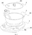
FIG. 2 is a schematic diagram illustrating that a temperature measuring and overflow preventing probe for a pot is placed in a pot of the present disclosure. -
FIG. 3 is a schematic diagram illustrating that a temperature measuring and overflow preventing probe for a pot is connected with a data wire and plugged into a pot from a pot cover. -
FIG. 4 is a circuit block diagram in a temperature measuring and overflow preventing probe for a pot of the present disclosure. -
FIG. 5 is a schematic structural diagram of a circuit in a base of the present disclosure. - The present disclosure is further described in detail below in combination with the accompanying drawings and embodiments. A temperature measuring and overflow preventing probe of the present disclosure is a detecting device used for a small household pot, such as a soup pot, a health pot, and an electromagnetic heating pot.
- As shown in
FIG. 1 , the detecting device is aprobe 1. Theprobe 1 is provided with ahead part 108 and aprobe needle 102 connected below thehead part 108. - The
head part 108 is provided with a hemispheric shell with an upward opening; the shell is provided with a cover with aportable buckle 105; the exterior of thehead part 108 is connected with ahook 106; and the shell of thehead part 108 is also provided with acharging interface 103. - As shown in
FIG. 4 , a first micro control unit (MCU) is arranged in the hemispheric shell; the first MCU is connected with atemperature sensor 104, a first Bluetoothmodule 101, and a rechargeable battery module. The rechargeable battery module includes a battery and a charging circuit. The charging circuit is electrically connected to thecharging interface 103. The battery and the charging circuit supply power to the first MCU and the first Bluetoothmodule 101. - The
probe needle 102 is of a vertically downward cylindrical structure, the lower end of which is closed and the upper end of which is opened. The lower part of theprobe needle 102 is atemperature detecting part 1021, and the upper part is anoverflow detecting part 1022; acylindrical connection part 1024 is connected between thetemperature detecting part 1021 and theoverflow detecting part 1022 in a sleeved manner; and theconnection part 1024 fixedly connects thetemperature detecting part 1021 to theoverflow detecting part 1022 to form a whole. The upper end of theoverflow detecting part 1022 is fixedly connected with the shell of thehead part 108. - An
output end 1041 of thetemperature sensor 104 is electrically connected with the first MCU in theprobe needle 102. A temperature sensing head of thetemperature sensor 104 extends into thetemperature detecting part 1021 and is in tight fit with the lower end part of thetemperature detecting part 1021. - The
temperature detecting part 1021 and theoverflow detecting part 1022 of theprobe needle 102 use a thermal and conductive material, such as copper or stainless steel, and theconnection part 1024 uses an insulation material, such as plastic. Theoverflow detecting part 1022 is connected to an overflow preventingoutput end 1025 through a rivet or asolder pad 1023 in a riveted or soldered manner, and the overflow preventingoutput end 1025 is electrically connected to the first MCU. - During cooking of food in the pot, when water at the lower part of the pot is boiled, and water bubbles rise up and exceed the
connection part 1024, theoverflow detecting part 1022 and thetemperature detecting part 1021 are connected to generate a varying signal of a resistance value that is transmitted to the first MCU via the overflow preventingoutput end 1025. - The
probe needle 102 has an outer diameter of 3 to 15 mm, preferably 10 mm, and a length that is a distance of 3 to 50 mm between the end part of thetemperature detecting part 1021 and the bottom surface of the pot body, preferably 20 mm. A distance from a joint of thetemperature detecting part 1022 and theconnection part 1024 to an upper opening of apot body 3 is 15 to 40 mm, preferably 20 mm. - As shown in
FIG. 2 , thepot body 3 of the small household pot is placed on abase 4, and thepot body 3 and thebase 4 form separable connection. Thebase 4 is provided with acharging socket 401. As shown inFIG. 3 , the rechargeable battery module of thehead part 108 of theprobe 1 is electrically connected to thecharging socket 401 through adata wire 5 to charge the rechargeable battery module of thehead part 108. - A pot cover 2 covers the upper opening of the
pot body 3. The middle of the pot cover 2 is connected with ahandle 201. A throughhole 202 is formed in the pot cover 2. Theprobe needle 102 of theprobe 1 is plugged into the throughhole 202 of the pot cover 2 and extends into thepot body 3. - As shown in
FIG. 5 , a second MCU is arranged in thebase 4, and is connected with a second Bluetooth module, a power control circuit and a power supply circuit, and the power control circuit is connected with a heat generating element. The first Bluetoothmodule 101 and the second Bluetooth module are wirelessly connected for signal transmission to control a switch and power of the heat generating element. - The
probe 1 is connected to thecharging socket 401 through thedata wire 5 to realize charging. - A working process of the temperature measuring and overflow preventing probe for a pot of the present disclosure:
- During use of the temperature measuring and overflow preventing probe for a pot of the present disclosure, firstly, food needing to be cooked is put into the
pot body 3, and a proper amount of water is added; and then, thepot body 3 is placed on thebase 4. At this time, the bottom of thepot body 3 is in tight fit with the heat generating element on the upper surface of thebase 4, and the pot cover 2 covers the upper opening of thepot body 3. - The
probe needle 102 of theprobe 1 is aligned with and plugged into the throughhole 202 of the pot cover 2, so that theprobe needle 102 directly extends into the food or soup in thepot body 3; and thehead part 108 of theprobe 1 is locked on the pot cover 2 by the throughhole 202 to enable theprobe 1 to be stably fixed on the pot cover 2. At this time, thetemperature detecting part 1021 in theprobe 1 has been soaked into liquid of the soup, and the distance from the joint of theoverflow detecting part 1022 in theprobe 1 and theconnection part 1024 to the upper opening of the pot is 15 to 40 mm. - Function setting is performed by selecting a
button 402 on thebase 4. When a "start" button is pressed, the pot starts to cook food or soup. The power control circuit on thebase 4 starts to control the heat generating element to generate heat, and the bottom of thepot body 3 is heated by the heat generating element to heat the liquid in thepot body 3. - The
first Bluetooth module 101 in theprobe 1 starts to work and communicates with the second Bluetooth module in thebase 4. After it is confirmed for the first time that the communication connection succeeds, when theprobe 1 and thebase 4 which are in communication connection are used, or when a mobile terminal in communication connection with theprobe 1 is used (the mobile terminal may be a mobile phone or a flat computer, such as IPAD), signal transmission can be automatically realized. - The
temperature sensor 104 in theprobe 1 starts to sense a temperature change of thetemperature detecting part 1021. Thetemperature detecting part 1021 changes as the temperature in thepot body 3 changes. Theoverflow detecting part 1022 starts to detect whether there is a water bubble rising up to the joint of the overflow detecting part and theconnection part 1024. It is indicated that water is to overflow if a short circuit is formed between theoverflow detecting part 1022 and thetemperature detecting part 1021. - If the
temperature sensor 104 senses a temperature change of thetemperature detecting part 1021 and theoverflow detecting part 1022 detects water bubbles and is connected to thetemperature detecting part 1021, the generated varying signal of the resistance value is collected by the first MCU. After being processed according to the existing technology, the signal is transmitted to the second Bluetooth module in thebase 4 through thefirst Bluetooth module 101, or is received by a third Bluetooth module connected with the mobile terminal. The third Bluetooth module connected with the mobile terminal performs processing in the second MCU in thebase 4 of the mobile phone or the IPAD to control the power control circuit to control the heating element to generate or not generate heat. If the mobile terminal such as the mobile phone or the IPAD receives temperature change information sent from thefirst Bluetooth module 101 in thehead part 108, the information can be instantly displayed on an APP of the mobile phone or the IPAD for a user to learn about a working state in thepot body 3. - The
first Bluetooth module 101 in thehead part 108 is powered by the rechargeable battery. When the rechargeable battery of thehead part 108 has no power, the rechargeable battery can be charged by connecting the charginginterface 103 arranged on thehead part 108 to the chargingsocket 401 arranged on thebase 4 by means of thecharging wire 5. - The present disclosure can be used to detect the temperature in a pot body of a soup pot, a pot on an electromagnetic oven or other separable pots and prevent overflow, and is convenient and safe. The present disclosure uses the Bluetooth modules to perform signal transmission, and can also use WiFi signals for interconnection transmission.
- Temperatures in electric appliances such as a pot and a health pot in the existing technology are detected by installing a temperature sensor on a heating element in a pot body, and overflow is also detected by disposing a special overflow preventing probe on or in the pot body, or disposing an overflow preventing probe at the upper part or mouth part of the pot body. The arrangement of these overflow preventing probes increases the difficulty of designing and machining structures of these pot bodies and pot covers and increases unnecessary cost. Meanwhile, the MCUs, Bluetooth, the temperature sensor, the rechargeable battery and the charging circuit are arranged in the probe of the present disclosure, and the temperature sensing part of the temperature sensor is in tight fit with the head of a temperature detecting rod, so that temperature data can be transmitted to the base and the mobile terminal through the Bluetooth to control heating of the pot or the health pot. The temperature of food in the pot or the health pot can be checked in time through the mobile terminal, which brings a great convenience to consumers' use.
- In the temperature measuring and overflow preventing probe of the present disclosure, the MCUs, the Bluetooth and the charging module are integrated together are disposed at the head part of the probe. Two sections of probe needles are used, i.e., one section for temperature measuring and one section for overflow preventing. Wireless control or wired control can be used, so that the product cost is effectively reduced, and the user experience is also enhanced.
Claims (10)
- A temperature measuring and overflow preventing probe for a pot, wherein the temperature measuring and overflow preventing probe for a pot is provided with a head part (108) and a probe needle (102) connected below the head part (108); the probe needle (102) is a vertically downward cylindrical structure; the lower part of the probe needle (102) is a temperature detecting part (1021), characterized in that the upper part is an overflow detecting part (1022); and in that it further comprises a cylindrical connection part (1024) connected between the temperature detecting part (1021) and the overflow detecting part (1022); and in that
the connection part (1024) fixedly connects the temperature detecting part (1021) to the overflow detecting part (1022) to form a whole; the temperature detecting part (1021) and the overflow detecting part (1022) use conductive materials; and the connection part (1024) uses an insulation material. - The temperature measuring and overflow preventing probe for the pot according to claim 1, wherein a first micro control unit (MCU) is arranged in the head part (108), and the overflow detecting part (1022) is electrically connected with the first MCU.
- The temperature measuring and overflow preventing probe for the pot according to claim 2, wherein the overflow detecting part (1022) is connected to an overflow preventing output end (1025) through a rivet or a solder pad (1023) in a riveted or soldered manner, and the overflow preventing output end (1025) is electrically connected to the first MCU.
- The temperature measuring and overflow preventing probe for the pot according to claim 3, wherein the first MCU is connected with a temperature sensor (104), a first Bluetooth module (101) and a rechargeable battery module.
- The temperature measuring and overflow preventing probe for the pot according to claim 4, wherein the probe needle (102) is plugged into a through hole (202) in a pot cover (2) and extends into a pot body (3).
- The temperature measuring and overflow preventing probe for the pot according to claim 5, wherein the pot body (3) is arranged on a base (4) to form separable connection to the base (4); the base (4) is provided with a charging socket (401); and the rechargeable battery module of the head part (108) is electrically connected with the charging socket (401) through a data wire (5).
- The temperature measuring and overflow preventing probe for the pot according to claim 6, wherein a second MCU is connected with a second Bluetooth module, a power control circuit and a power supply circuit, and the power control circuit is connected with a heat generating element.
- The temperature measuring and overflow preventing probe for the pot according to claim 7, wherein the first Bluetooth module (101) and the second Bluetooth module are wirelessly connected to control a switch and power of the heat generating element.
- The temperature measuring and overflow preventing probe for the pot according to claim 1, wherein the lower end of the probe needle (102) is closed, and the upper end is opened.
- The temperature measuring and overflow preventing probe for the pot according to claim 1, wherein the upper end of the overflow detecting part (1022) is fixedly connected with a shell of the head part (108).
Applications Claiming Priority (1)
| Application Number | Priority Date | Filing Date | Title |
|---|---|---|---|
| CN202010664999.5A CN111700513A (en) | 2020-07-10 | 2020-07-10 | Pot temperature measuring and anti-overflow probe |
Publications (2)
| Publication Number | Publication Date |
|---|---|
| EP3936008A1 EP3936008A1 (en) | 2022-01-12 |
| EP3936008B1 true EP3936008B1 (en) | 2022-11-02 |
Family
ID=72545599
Family Applications (1)
| Application Number | Title | Priority Date | Filing Date |
|---|---|---|---|
| EP21183364.5A Active EP3936008B1 (en) | 2020-07-10 | 2021-07-02 | Temperature measuring and overflow preventing probe for pot |
Country Status (3)
| Country | Link |
|---|---|
| US (1) | US12022972B2 (en) |
| EP (1) | EP3936008B1 (en) |
| CN (1) | CN111700513A (en) |
Family Cites Families (24)
| Publication number | Priority date | Publication date | Assignee | Title |
|---|---|---|---|---|
| US4346836A (en) * | 1977-07-11 | 1982-08-31 | Nagel Louis F | Pressure cooker canning unit |
| US4817510A (en) * | 1986-04-09 | 1989-04-04 | The Meyer Company | Cooking apparatus for fluid container |
| US4982655A (en) * | 1990-02-13 | 1991-01-08 | Wen Der Juang | Saucepan capable of setting amount of soup finally left therein |
| GB9409296D0 (en) * | 1994-05-10 | 1994-06-29 | Alba Tools Ltd | Brake fluid analyser |
| JPH0910103A (en) * | 1995-06-28 | 1997-01-14 | Toshiba Corp | Cooker |
| US6433693B1 (en) * | 2000-07-31 | 2002-08-13 | General Electric Company | Apparatus and method for boil phase detection based on acoustic signal features |
| US6980417B2 (en) * | 2003-11-13 | 2005-12-27 | Ken-Chao Chang | Meter with concealed probe receiving deck |
| US20130036917A1 (en) * | 2011-08-09 | 2013-02-14 | Marianne Berge | Stir lid with overflow sensor |
| EP3248516B1 (en) * | 2012-05-04 | 2019-09-04 | Electrolux Home Products Corporation N.V. | A temperature detection assembly and a temperature detection system for a cooking pot |
| CN203591156U (en) * | 2013-11-05 | 2014-05-14 | 上海市闵行中学 | Scorch-preventing overflowing-preventing safety pan |
| EP2910858B1 (en) * | 2014-02-20 | 2019-11-06 | Electrolux Appliances Aktiebolag | Method, computer program product and arrangement for guarding an automated process to operate a household appliance based on a sensor measurement to provide an expected process parameter |
| WO2015164174A1 (en) * | 2014-04-24 | 2015-10-29 | Silgan Containers Llc | Food container induction heating system having power based microbial lethality monitoring |
| JP7221689B2 (en) * | 2015-09-10 | 2023-02-14 | ブラバ・ホーム・インコーポレイテッド | in-oven camera |
| US10444080B2 (en) * | 2015-11-17 | 2019-10-15 | Haier Us Appliance Solutions, Inc. | Thermal management for a wireless cooking probe |
| US11766151B2 (en) * | 2016-02-18 | 2023-09-26 | Meyer Intellectual Properties Ltd. | Cooking system with error detection |
| KR102488774B1 (en) * | 2016-03-28 | 2023-01-13 | 엘지전자 주식회사 | Hanger-type cooking information provision device |
| CN206390751U (en) * | 2016-09-14 | 2017-08-11 | 浙江绍兴苏泊尔生活电器有限公司 | cooker for electromagnetic oven |
| CN106821017A (en) * | 2017-02-24 | 2017-06-13 | 广东美的厨房电器制造有限公司 | Temperature probe, cooking apparatus and method for heating and controlling |
| CN208799062U (en) * | 2017-06-30 | 2019-04-30 | 浙江绍兴苏泊尔生活电器有限公司 | Anti-overflow structure and have its cooking ware |
| CN207604842U (en) * | 2017-06-30 | 2018-07-13 | 浙江绍兴苏泊尔生活电器有限公司 | Induction Cooker Pots and Induction Cooker Cookware |
| CN208463683U (en) * | 2018-03-05 | 2019-02-05 | 浙江绍兴苏泊尔生活电器有限公司 | Pots and Induction Cookware |
| CN109770724A (en) * | 2018-12-21 | 2019-05-21 | 广东伊莱特电器有限公司 | A pot with an external temperature sensor |
| US11486769B2 (en) * | 2019-12-05 | 2022-11-01 | Haier US Appliance Solutions, Inc | Temperature probe for a cooktop appliance with a gas burner |
| CN212878967U (en) * | 2020-07-10 | 2021-04-06 | 深圳市北鼎科技有限公司 | Temp. measuring anti-overflow probe for pot |
-
2020
- 2020-07-10 CN CN202010664999.5A patent/CN111700513A/en active Pending
-
2021
- 2021-07-02 US US17/366,040 patent/US12022972B2/en active Active
- 2021-07-02 EP EP21183364.5A patent/EP3936008B1/en active Active
Also Published As
| Publication number | Publication date |
|---|---|
| US20220007874A1 (en) | 2022-01-13 |
| US12022972B2 (en) | 2024-07-02 |
| CN111700513A (en) | 2020-09-25 |
| EP3936008A1 (en) | 2022-01-12 |
Similar Documents
| Publication | Publication Date | Title |
|---|---|---|
| CN105640299B (en) | SMART COOKWARE with firepower prompting | |
| CN205197727U (en) | Intelligence temperature measurement cooking utensil with from generating function | |
| CN201542392U (en) | Food heating cooker | |
| CN206491659U (en) | Intelligent pan | |
| US11219333B2 (en) | Wireless temperature sensing system for a cooking appliance | |
| CN105125058A (en) | Intelligent temperature measuring cooker with self-generating function | |
| CN106691163A (en) | Intelligent pot | |
| CN208461536U (en) | A kind of heating device | |
| EP2681491A2 (en) | Universal device for energy control in the form of a button | |
| US12022972B2 (en) | Temperature measuring and overflow preventing probe for pot | |
| CN103531016B (en) | Separated liquid heater and signal infrared transmission method thereof | |
| CN212878967U (en) | Temp. measuring anti-overflow probe for pot | |
| CN206193471U (en) | Frying pan intelligence control system | |
| CN213345246U (en) | Temperature measuring structure of health preserving kettle | |
| CN109770724A (en) | A pot with an external temperature sensor | |
| CN111449493A (en) | Health pot temperature measurement structure | |
| CN109683511A (en) | A kind of intelligence stirring rod | |
| CN216221261U (en) | Strainer with temperature measurement and timing functions | |
| CN211933659U (en) | Multifunctional intelligent kettle | |
| CN203723913U (en) | Intelligent coffeepot | |
| CN207096730U (en) | Split cooking apparatus | |
| CN208610579U (en) | An IH electric kettle | |
| CN209027692U (en) | Temperature measurement equipment used in high temperature and high pressure brewing machines | |
| CN215127463U (en) | Beverage heating device | |
| CN209863292U (en) | Cooking utensil |
Legal Events
| Date | Code | Title | Description |
|---|---|---|---|
| PUAI | Public reference made under article 153(3) epc to a published international application that has entered the european phase |
Free format text: ORIGINAL CODE: 0009012 |
|
| STAA | Information on the status of an ep patent application or granted ep patent |
Free format text: STATUS: REQUEST FOR EXAMINATION WAS MADE |
|
| 17P | Request for examination filed |
Effective date: 20210702 |
|
| AK | Designated contracting states |
Kind code of ref document: A1 Designated state(s): AL AT BE BG CH CY CZ DE DK EE ES FI FR GB GR HR HU IE IS IT LI LT LU LV MC MK MT NL NO PL PT RO RS SE SI SK SM TR |
|
| B565 | Issuance of search results under rule 164(2) epc |
Effective date: 20211213 |
|
| GRAP | Despatch of communication of intention to grant a patent |
Free format text: ORIGINAL CODE: EPIDOSNIGR1 |
|
| STAA | Information on the status of an ep patent application or granted ep patent |
Free format text: STATUS: GRANT OF PATENT IS INTENDED |
|
| RIC1 | Information provided on ipc code assigned before grant |
Ipc: A47J 36/32 20060101ALI20220512BHEP Ipc: A47J 27/56 20060101AFI20220512BHEP |
|
| INTG | Intention to grant announced |
Effective date: 20220607 |
|
| GRAS | Grant fee paid |
Free format text: ORIGINAL CODE: EPIDOSNIGR3 |
|
| GRAA | (expected) grant |
Free format text: ORIGINAL CODE: 0009210 |
|
| STAA | Information on the status of an ep patent application or granted ep patent |
Free format text: STATUS: THE PATENT HAS BEEN GRANTED |
|
| AK | Designated contracting states |
Kind code of ref document: B1 Designated state(s): AL AT BE BG CH CY CZ DE DK EE ES FI FR GB GR HR HU IE IS IT LI LT LU LV MC MK MT NL NO PL PT RO RS SE SI SK SM TR |
|
| REG | Reference to a national code |
Ref country code: GB Ref legal event code: FG4D |
|
| REG | Reference to a national code |
Ref country code: CH Ref legal event code: EP Ref country code: AT Ref legal event code: REF Ref document number: 1528119 Country of ref document: AT Kind code of ref document: T Effective date: 20221115 |
|
| REG | Reference to a national code |
Ref country code: DE Ref legal event code: R096 Ref document number: 602021000675 Country of ref document: DE |
|
| REG | Reference to a national code |
Ref country code: IE Ref legal event code: FG4D |
|
| REG | Reference to a national code |
Ref country code: LT Ref legal event code: MG9D |
|
| REG | Reference to a national code |
Ref country code: NL Ref legal event code: MP Effective date: 20221102 |
|
| REG | Reference to a national code |
Ref country code: AT Ref legal event code: MK05 Ref document number: 1528119 Country of ref document: AT Kind code of ref document: T Effective date: 20221102 |
|
| PG25 | Lapsed in a contracting state [announced via postgrant information from national office to epo] |
Ref country code: SE Free format text: LAPSE BECAUSE OF FAILURE TO SUBMIT A TRANSLATION OF THE DESCRIPTION OR TO PAY THE FEE WITHIN THE PRESCRIBED TIME-LIMIT Effective date: 20221102 Ref country code: PT Free format text: LAPSE BECAUSE OF FAILURE TO SUBMIT A TRANSLATION OF THE DESCRIPTION OR TO PAY THE FEE WITHIN THE PRESCRIBED TIME-LIMIT Effective date: 20230302 Ref country code: NO Free format text: LAPSE BECAUSE OF FAILURE TO SUBMIT A TRANSLATION OF THE DESCRIPTION OR TO PAY THE FEE WITHIN THE PRESCRIBED TIME-LIMIT Effective date: 20230202 Ref country code: LT Free format text: LAPSE BECAUSE OF FAILURE TO SUBMIT A TRANSLATION OF THE DESCRIPTION OR TO PAY THE FEE WITHIN THE PRESCRIBED TIME-LIMIT Effective date: 20221102 Ref country code: FI Free format text: LAPSE BECAUSE OF FAILURE TO SUBMIT A TRANSLATION OF THE DESCRIPTION OR TO PAY THE FEE WITHIN THE PRESCRIBED TIME-LIMIT Effective date: 20221102 Ref country code: ES Free format text: LAPSE BECAUSE OF FAILURE TO SUBMIT A TRANSLATION OF THE DESCRIPTION OR TO PAY THE FEE WITHIN THE PRESCRIBED TIME-LIMIT Effective date: 20221102 Ref country code: AT Free format text: LAPSE BECAUSE OF FAILURE TO SUBMIT A TRANSLATION OF THE DESCRIPTION OR TO PAY THE FEE WITHIN THE PRESCRIBED TIME-LIMIT Effective date: 20221102 |
|
| PG25 | Lapsed in a contracting state [announced via postgrant information from national office to epo] |
Ref country code: RS Free format text: LAPSE BECAUSE OF FAILURE TO SUBMIT A TRANSLATION OF THE DESCRIPTION OR TO PAY THE FEE WITHIN THE PRESCRIBED TIME-LIMIT Effective date: 20221102 Ref country code: PL Free format text: LAPSE BECAUSE OF FAILURE TO SUBMIT A TRANSLATION OF THE DESCRIPTION OR TO PAY THE FEE WITHIN THE PRESCRIBED TIME-LIMIT Effective date: 20221102 Ref country code: LV Free format text: LAPSE BECAUSE OF FAILURE TO SUBMIT A TRANSLATION OF THE DESCRIPTION OR TO PAY THE FEE WITHIN THE PRESCRIBED TIME-LIMIT Effective date: 20221102 Ref country code: IS Free format text: LAPSE BECAUSE OF FAILURE TO SUBMIT A TRANSLATION OF THE DESCRIPTION OR TO PAY THE FEE WITHIN THE PRESCRIBED TIME-LIMIT Effective date: 20230302 Ref country code: HR Free format text: LAPSE BECAUSE OF FAILURE TO SUBMIT A TRANSLATION OF THE DESCRIPTION OR TO PAY THE FEE WITHIN THE PRESCRIBED TIME-LIMIT Effective date: 20221102 Ref country code: GR Free format text: LAPSE BECAUSE OF FAILURE TO SUBMIT A TRANSLATION OF THE DESCRIPTION OR TO PAY THE FEE WITHIN THE PRESCRIBED TIME-LIMIT Effective date: 20230203 |
|
| PG25 | Lapsed in a contracting state [announced via postgrant information from national office to epo] |
Ref country code: NL Free format text: LAPSE BECAUSE OF FAILURE TO SUBMIT A TRANSLATION OF THE DESCRIPTION OR TO PAY THE FEE WITHIN THE PRESCRIBED TIME-LIMIT Effective date: 20221102 |
|
| PG25 | Lapsed in a contracting state [announced via postgrant information from national office to epo] |
Ref country code: SM Free format text: LAPSE BECAUSE OF FAILURE TO SUBMIT A TRANSLATION OF THE DESCRIPTION OR TO PAY THE FEE WITHIN THE PRESCRIBED TIME-LIMIT Effective date: 20221102 Ref country code: RO Free format text: LAPSE BECAUSE OF FAILURE TO SUBMIT A TRANSLATION OF THE DESCRIPTION OR TO PAY THE FEE WITHIN THE PRESCRIBED TIME-LIMIT Effective date: 20221102 Ref country code: EE Free format text: LAPSE BECAUSE OF FAILURE TO SUBMIT A TRANSLATION OF THE DESCRIPTION OR TO PAY THE FEE WITHIN THE PRESCRIBED TIME-LIMIT Effective date: 20221102 Ref country code: DK Free format text: LAPSE BECAUSE OF FAILURE TO SUBMIT A TRANSLATION OF THE DESCRIPTION OR TO PAY THE FEE WITHIN THE PRESCRIBED TIME-LIMIT Effective date: 20221102 Ref country code: CZ Free format text: LAPSE BECAUSE OF FAILURE TO SUBMIT A TRANSLATION OF THE DESCRIPTION OR TO PAY THE FEE WITHIN THE PRESCRIBED TIME-LIMIT Effective date: 20221102 |
|
| REG | Reference to a national code |
Ref country code: DE Ref legal event code: R097 Ref document number: 602021000675 Country of ref document: DE |
|
| PG25 | Lapsed in a contracting state [announced via postgrant information from national office to epo] |
Ref country code: SK Free format text: LAPSE BECAUSE OF FAILURE TO SUBMIT A TRANSLATION OF THE DESCRIPTION OR TO PAY THE FEE WITHIN THE PRESCRIBED TIME-LIMIT Effective date: 20221102 Ref country code: AL Free format text: LAPSE BECAUSE OF FAILURE TO SUBMIT A TRANSLATION OF THE DESCRIPTION OR TO PAY THE FEE WITHIN THE PRESCRIBED TIME-LIMIT Effective date: 20221102 |
|
| PLBE | No opposition filed within time limit |
Free format text: ORIGINAL CODE: 0009261 |
|
| STAA | Information on the status of an ep patent application or granted ep patent |
Free format text: STATUS: NO OPPOSITION FILED WITHIN TIME LIMIT |
|
| 26N | No opposition filed |
Effective date: 20230803 |
|
| PG25 | Lapsed in a contracting state [announced via postgrant information from national office to epo] |
Ref country code: SI Free format text: LAPSE BECAUSE OF FAILURE TO SUBMIT A TRANSLATION OF THE DESCRIPTION OR TO PAY THE FEE WITHIN THE PRESCRIBED TIME-LIMIT Effective date: 20221102 |
|
| PG25 | Lapsed in a contracting state [announced via postgrant information from national office to epo] |
Ref country code: MC Free format text: LAPSE BECAUSE OF FAILURE TO SUBMIT A TRANSLATION OF THE DESCRIPTION OR TO PAY THE FEE WITHIN THE PRESCRIBED TIME-LIMIT Effective date: 20221102 |
|
| PG25 | Lapsed in a contracting state [announced via postgrant information from national office to epo] |
Ref country code: MC Free format text: LAPSE BECAUSE OF FAILURE TO SUBMIT A TRANSLATION OF THE DESCRIPTION OR TO PAY THE FEE WITHIN THE PRESCRIBED TIME-LIMIT Effective date: 20221102 |
|
| REG | Reference to a national code |
Ref country code: BE Ref legal event code: MM Effective date: 20230731 |
|
| PG25 | Lapsed in a contracting state [announced via postgrant information from national office to epo] |
Ref country code: LU Free format text: LAPSE BECAUSE OF NON-PAYMENT OF DUE FEES Effective date: 20230702 |
|
| PG25 | Lapsed in a contracting state [announced via postgrant information from national office to epo] |
Ref country code: LU Free format text: LAPSE BECAUSE OF NON-PAYMENT OF DUE FEES Effective date: 20230702 |
|
| REG | Reference to a national code |
Ref country code: IE Ref legal event code: MM4A |
|
| PG25 | Lapsed in a contracting state [announced via postgrant information from national office to epo] |
Ref country code: IT Free format text: LAPSE BECAUSE OF FAILURE TO SUBMIT A TRANSLATION OF THE DESCRIPTION OR TO PAY THE FEE WITHIN THE PRESCRIBED TIME-LIMIT Effective date: 20221102 Ref country code: BE Free format text: LAPSE BECAUSE OF NON-PAYMENT OF DUE FEES Effective date: 20230731 |
|
| PG25 | Lapsed in a contracting state [announced via postgrant information from national office to epo] |
Ref country code: IE Free format text: LAPSE BECAUSE OF NON-PAYMENT OF DUE FEES Effective date: 20230702 |
|
| PG25 | Lapsed in a contracting state [announced via postgrant information from national office to epo] |
Ref country code: IE Free format text: LAPSE BECAUSE OF NON-PAYMENT OF DUE FEES Effective date: 20230702 |
|
| PG25 | Lapsed in a contracting state [announced via postgrant information from national office to epo] |
Ref country code: BG Free format text: LAPSE BECAUSE OF FAILURE TO SUBMIT A TRANSLATION OF THE DESCRIPTION OR TO PAY THE FEE WITHIN THE PRESCRIBED TIME-LIMIT Effective date: 20221102 |
|
| PG25 | Lapsed in a contracting state [announced via postgrant information from national office to epo] |
Ref country code: BG Free format text: LAPSE BECAUSE OF FAILURE TO SUBMIT A TRANSLATION OF THE DESCRIPTION OR TO PAY THE FEE WITHIN THE PRESCRIBED TIME-LIMIT Effective date: 20221102 |
|
| REG | Reference to a national code |
Ref country code: CH Ref legal event code: PL |
|
| PG25 | Lapsed in a contracting state [announced via postgrant information from national office to epo] |
Ref country code: CH Free format text: LAPSE BECAUSE OF NON-PAYMENT OF DUE FEES Effective date: 20240731 |
|
| PGFP | Annual fee paid to national office [announced via postgrant information from national office to epo] |
Ref country code: GB Payment date: 20250528 Year of fee payment: 5 |
|
| PG25 | Lapsed in a contracting state [announced via postgrant information from national office to epo] |
Ref country code: CY Free format text: LAPSE BECAUSE OF FAILURE TO SUBMIT A TRANSLATION OF THE DESCRIPTION OR TO PAY THE FEE WITHIN THE PRESCRIBED TIME-LIMIT; INVALID AB INITIO Effective date: 20210702 |
|
| PG25 | Lapsed in a contracting state [announced via postgrant information from national office to epo] |
Ref country code: HU Free format text: LAPSE BECAUSE OF FAILURE TO SUBMIT A TRANSLATION OF THE DESCRIPTION OR TO PAY THE FEE WITHIN THE PRESCRIBED TIME-LIMIT; INVALID AB INITIO Effective date: 20210702 |
|
| PGFP | Annual fee paid to national office [announced via postgrant information from national office to epo] |
Ref country code: DE Payment date: 20250711 Year of fee payment: 5 |
|
| PGFP | Annual fee paid to national office [announced via postgrant information from national office to epo] |
Ref country code: FR Payment date: 20250730 Year of fee payment: 5 |
|
| PG25 | Lapsed in a contracting state [announced via postgrant information from national office to epo] |
Ref country code: TR Free format text: LAPSE BECAUSE OF FAILURE TO SUBMIT A TRANSLATION OF THE DESCRIPTION OR TO PAY THE FEE WITHIN THE PRESCRIBED TIME-LIMIT Effective date: 20221102 |