EP3935483B1 - Industry standard interface for maintenance of enterprise systems - Google Patents
Industry standard interface for maintenance of enterprise systems Download PDFInfo
- Publication number
- EP3935483B1 EP3935483B1 EP20766534.0A EP20766534A EP3935483B1 EP 3935483 B1 EP3935483 B1 EP 3935483B1 EP 20766534 A EP20766534 A EP 20766534A EP 3935483 B1 EP3935483 B1 EP 3935483B1
- Authority
- EP
- European Patent Office
- Prior art keywords
- ldap
- external
- directories
- interface
- data
- Prior art date
- Legal status (The legal status is an assumption and is not a legal conclusion. Google has not performed a legal analysis and makes no representation as to the accuracy of the status listed.)
- Active
Links
Images




Classifications
-
- G—PHYSICS
- G06—COMPUTING OR CALCULATING; COUNTING
- G06F—ELECTRIC DIGITAL DATA PROCESSING
- G06F16/00—Information retrieval; Database structures therefor; File system structures therefor
- G06F16/20—Information retrieval; Database structures therefor; File system structures therefor of structured data, e.g. relational data
- G06F16/28—Databases characterised by their database models, e.g. relational or object models
- G06F16/282—Hierarchical databases, e.g. IMS, LDAP data stores or Lotus Notes
-
- G—PHYSICS
- G06—COMPUTING OR CALCULATING; COUNTING
- G06F—ELECTRIC DIGITAL DATA PROCESSING
- G06F16/00—Information retrieval; Database structures therefor; File system structures therefor
- G06F16/20—Information retrieval; Database structures therefor; File system structures therefor of structured data, e.g. relational data
- G06F16/25—Integrating or interfacing systems involving database management systems
- G06F16/256—Integrating or interfacing systems involving database management systems in federated or virtual databases
-
- G—PHYSICS
- G06—COMPUTING OR CALCULATING; COUNTING
- G06Q—INFORMATION AND COMMUNICATION TECHNOLOGY [ICT] SPECIALLY ADAPTED FOR ADMINISTRATIVE, COMMERCIAL, FINANCIAL, MANAGERIAL OR SUPERVISORY PURPOSES; SYSTEMS OR METHODS SPECIALLY ADAPTED FOR ADMINISTRATIVE, COMMERCIAL, FINANCIAL, MANAGERIAL OR SUPERVISORY PURPOSES, NOT OTHERWISE PROVIDED FOR
- G06Q10/00—Administration; Management
- G06Q10/10—Office automation; Time management
- G06Q10/105—Human resources
-
- H—ELECTRICITY
- H04—ELECTRIC COMMUNICATION TECHNIQUE
- H04L—TRANSMISSION OF DIGITAL INFORMATION, e.g. TELEGRAPHIC COMMUNICATION
- H04L61/00—Network arrangements, protocols or services for addressing or naming
- H04L61/45—Network directories; Name-to-address mapping
- H04L61/4505—Network directories; Name-to-address mapping using standardised directories; using standardised directory access protocols
- H04L61/4523—Network directories; Name-to-address mapping using standardised directories; using standardised directory access protocols using lightweight directory access protocol [LDAP]
-
- H—ELECTRICITY
- H04—ELECTRIC COMMUNICATION TECHNIQUE
- H04L—TRANSMISSION OF DIGITAL INFORMATION, e.g. TELEGRAPHIC COMMUNICATION
- H04L61/00—Network arrangements, protocols or services for addressing or naming
- H04L61/45—Network directories; Name-to-address mapping
- H04L61/4552—Lookup mechanisms between a plurality of directories; Synchronisation of directories, e.g. metadirectories
-
- H—ELECTRICITY
- H04—ELECTRIC COMMUNICATION TECHNIQUE
- H04L—TRANSMISSION OF DIGITAL INFORMATION, e.g. TELEGRAPHIC COMMUNICATION
- H04L63/00—Network architectures or network communication protocols for network security
- H04L63/10—Network architectures or network communication protocols for network security for controlling access to devices or network resources
- H04L63/101—Access control lists [ACL]
-
- H—ELECTRICITY
- H04—ELECTRIC COMMUNICATION TECHNIQUE
- H04L—TRANSMISSION OF DIGITAL INFORMATION, e.g. TELEGRAPHIC COMMUNICATION
- H04L67/00—Network arrangements or protocols for supporting network services or applications
- H04L67/01—Protocols
- H04L67/10—Protocols in which an application is distributed across nodes in the network
- H04L67/1095—Replication or mirroring of data, e.g. scheduling or transport for data synchronisation between network nodes
-
- H—ELECTRICITY
- H04—ELECTRIC COMMUNICATION TECHNIQUE
- H04L—TRANSMISSION OF DIGITAL INFORMATION, e.g. TELEGRAPHIC COMMUNICATION
- H04L67/00—Network arrangements or protocols for supporting network services or applications
- H04L67/2866—Architectures; Arrangements
- H04L67/30—Profiles
- H04L67/306—User profiles
-
- H—ELECTRICITY
- H04—ELECTRIC COMMUNICATION TECHNIQUE
- H04L—TRANSMISSION OF DIGITAL INFORMATION, e.g. TELEGRAPHIC COMMUNICATION
- H04L67/00—Network arrangements or protocols for supporting network services or applications
- H04L67/50—Network services
- H04L67/56—Provisioning of proxy services
- H04L67/568—Storing data temporarily at an intermediate stage, e.g. caching
-
- H—ELECTRICITY
- H04—ELECTRIC COMMUNICATION TECHNIQUE
- H04L—TRANSMISSION OF DIGITAL INFORMATION, e.g. TELEGRAPHIC COMMUNICATION
- H04L69/00—Network arrangements, protocols or services independent of the application payload and not provided for in the other groups of this subclass
- H04L69/30—Definitions, standards or architectural aspects of layered protocol stacks
- H04L69/32—Architecture of open systems interconnection [OSI] 7-layer type protocol stacks, e.g. the interfaces between the data link level and the physical level
- H04L69/322—Intralayer communication protocols among peer entities or protocol data unit [PDU] definitions
- H04L69/329—Intralayer communication protocols among peer entities or protocol data unit [PDU] definitions in the application layer [OSI layer 7]
-
- H—ELECTRICITY
- H04—ELECTRIC COMMUNICATION TECHNIQUE
- H04L—TRANSMISSION OF DIGITAL INFORMATION, e.g. TELEGRAPHIC COMMUNICATION
- H04L63/00—Network architectures or network communication protocols for network security
- H04L63/08—Network architectures or network communication protocols for network security for authentication of entities
- H04L63/0884—Network architectures or network communication protocols for network security for authentication of entities by delegation of authentication, e.g. a proxy authenticates an entity to be authenticated on behalf of this entity vis-à-vis an authentication entity
Definitions
- the present disclosure relates generally to an improved computer system and, in particular, to synchronizing and managing enterprise data across multiple third party directories.
- An enterprise directory holds information on the resources in an enterprise. These resources can include user, groups, and hardware. Users and organizations might employ a wide variety of commoditized enterprise tools and directories to assist them in their day-to-day work, such as communications, productivity, and file management software. These different tools do not communicate with each other and might be implemented differently. All require organization data to be input, requiring the customer to set up and manage their access and entitlement across multiple systems.
- Managing multiple such tools requires regular manual updating of each system for routine organizational updates including, for example, creating new directory users when new employees are hired, removing users when employment ends, changing attributes (e.g., user name) on directory resources, and creating lists or groups of users in a directory.
- routine organizational updates including, for example, creating new directory users when new employees are hired, removing users when employment ends, changing attributes (e.g., user name) on directory resources, and creating lists or groups of users in a directory.
- US2003145003A1 describes a system and method which propagates change operations to data items within a metadirectory on a differential basis in order to minimize or eliminate redundant updates to attributes within data items that have not changed, as well as conserve computing resources and transmission bandwidth consumed by update activities in large organizations of data items.
- a best match entry in the metadirectory is selected using a weighted score process, a determination is made as to exactly which attributes are changed by the update operation, and a differential update is propagated throughout the metadirectory via direct joiner access to the data items, or through remote access such as through LDAP.
- US2012246112A1 describes a method may include storing a first database including a first plurality of user identifiers (IDs) and corresponding privileges for accessing network resources associated with an organization.
- the method may also include storing a second database, different than the first database, including the first plurality of user IDs.
- the method may also include storing a third database, different than the first database and second database, including a second plurality user IDs associated with the organization. Further, the method may include removing, from the first database, privileges associated with user IDs appearing in the second database but not in the third database.
- Oracle Fusion Middleware - Administrator's Guide for Oracle Virtual Directory provides information on how to utilize and administer Oracle Virtual Directory in an enterprise directory infrastructure.
- US2014156684A1 describes a lightweight directory access (LDAP) broker receives user information associated with a query for information in an LDAP repository.
- the query may be in an abstraction format.
- the LDAP broker determines a computing domain in view of the user information and retrieves a configuration file associated with the computing domain.
- the configuration file comprises a mapping for the query between an abstraction format and a vendor specific format.
- the LDAP broker converts the query to the vendor specific format in view of the mapping in the configuration file.
- the illustrative embodiments recognize and take into account one or more different considerations. For example, the illustrative embodiments recognize and take into account that organizations employing multiple external enterprise directories have to continually update and manage data across multiple systems which might be implemented differently and all require organization data. Such management across multiple systems is laborious and time consuming.
- the illustrative embodiments further recognize and take into account that manually managing and updating decentralized data across multiple systems can result in data that is inconsistent and not synchronized across these systems.
- the illustrative embodiments further recognize and take into account that time delays between employment termination and updating of directory user access creates potential securities risks to an organization.
- Illustrative embodiments provide an interface that allows users to automatically synchronize updated user and organization data across multiple external systems using a singular point of access while maintaining authorization with those external systems.
- FIG. 1 an illustration of a diagram of a data processing environment is depicted in accordance with an illustrative embodiment. It should be appreciated that Figure 1 is only provided as an illustration of one implementation and is not intended to imply any limitation with regard to the environments in which the different embodiments may be implemented. Many modifications to the depicted environments may be made.
- the computer-readable program instructions may also be loaded onto a computer, a programmable data processing apparatus, or other device to cause a series of operational steps to be performed on the computer, a programmable apparatus, or other device to produce a computer implemented process, such that the instructions which execute on the computer, the programmable apparatus, or the other device implement the functions and/or acts specified in the flowchart and/or block diagram block or blocks.
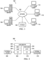
- FIG. 1 depicts a pictorial representation of a network of data processing systems in which illustrative embodiments may be implemented.
- Network data processing system 100 is a network of computers in which the illustrative embodiments may be implemented.
- Network data processing system 100 contains network 102, which is a medium used to provide communications links between various devices and computers connected together within network data processing system 100.
- Network 102 may include connections, such as wire, wireless communication links, or fiber optic cables.
- server computer 104 and server computer 106 connect to network 102 along with storage unit 108.
- client computers include client computer 110, client computer 112, and client computer 114.
- Client computer 110, client computer 112, and client computer 114 connect to network 102. These connections can be wireless or wired connections depending on the implementation.
- Client computer 110, client computer 112, and client computer 114 may be, for example, personal computers or network computers.
- server computer 104 provides information, such as boot files, operating system images, and applications to client computer 110, client computer 112, and client computer 114.
- Client computer 110, client computer 112, and client computer 114 are clients to server computer 104 in this example.
- Network data processing system 100 may include additional server computers, client computers, and other devices not shown.
- Program code located in network data processing system 100 may be stored on a computer-recordable storage medium and downloaded to a data processing system or other device for use.
- the program code may be stored on a computer-recordable storage medium on server computer 104 and downloaded to client computer 110 over network 102 for use on client computer 110.
- network data processing system 100 is the Internet with network 102 representing a worldwide collection of networks and gateways that use the Transmission Control Protocol/Internet Protocol (TCP/IP) suite of protocols to communicate with one another.
- TCP/IP Transmission Control Protocol/Internet Protocol
- At the heart of the Internet is a backbone of high-speed data communication lines between major nodes or host computers consisting of thousands of commercial, governmental, educational, and other computer systems that route data and messages.
- network data processing system 100 also may be implemented as a number of different types of networks, such as, for example, an intranet, a local area network (LAN), or a wide area network (WAN).
- Figure 1 is intended as an example, and not as an architectural limitation for the different illustrative embodiments.
- network data processing system 100 is not meant to limit the manner in which other illustrative embodiments can be implemented.
- client computers may be used in addition to or in place of client computer 110, client computer 112, and client computer 114 as depicted in Figure 1 .
- client computer 110, client computer 112, and client computer 114 may include a tablet computer, a laptop computer, a bus with a vehicle computer, and other suitable types of clients.
- the hardware may take the form of a circuit system, an integrated circuit, an application-specific integrated circuit (ASIC), a programmable logic device, or some other suitable type of hardware configured to perform a number of operations.
- ASIC application-specific integrated circuit
- the device may be configured to perform the number of operations.
- the device may be reconfigured at a later time or may be permanently configured to perform the number of operations.
- Programmable logic devices include, for example, a programmable logic array, programmable array logic, a field programmable logic array, a field programmable gate array, and other suitable hardware devices.
- the processes may be implemented in organic components integrated with inorganic components and may be comprised entirely of organic components, excluding a human being. For example, the processes may be implemented as circuits in organic semiconductors.
- System 200 comprises an internal system 202 such as, for example, a human resources (HR) database or similar platform.
- HR human resources
- LDAP lightweight directory access protocol
- the internal system 202 can be an HR platform or database with its own communications protocol 204.
- the internal system 202 can have multiple users 210 can be individuals or organizations.
- the user 220 among users 210 is an organization that has multiple employees 224.
- Each employee 226 among employees 224 has a set of attributes 228. These attributes can include personal identifying information as well as position and responsibilities within the user organization 220, including access privileges to enterprises services such as external systems 250.
- Groups of employees within a user organization 220 can be organized into different teams 230.
- Each team 232 within teams 230 has its own attributes 234, which define the membership and function of the team within the organization including access privileges of the team to enterprise services such as external systems 250. Access privileges to external systems listed in the attributes 228 of an employee can depend from the attributes 234 of a team 232 to which the employee belongs.
- an employee 226 might belong to multiple teams within team 230.
- the LDAP interface 240 provides a singular point of access for users 210 of internal system 202 to manage, update, and synchronize enterprise data across multiple external systems 250 through the Transmission Control Protocol/Internet Protocol (TCP/IP) protocol stack.
- LDAP 240 interface serves as a system of record data source
- LDAP is a request-response application protocol for accessing and maintaining distributed directory services.
- the LDAP interface 240 serves as a central repository for authorization attributes 244, including usernames and passwords and other access credentials.
- LDAP interface 240 provides a protocol transition 242 between the protocol 204 of internal system 202 and protocol 256 of external system 252, which might differ from the protocols from other systems among external systems 250.
- LDAP interface 240 acts as a layer over the internal HR system 202 that acts as a proxy for requests between the internal system 202 and external systems 250.
- LDAP interface 240 presents data on the external systems 250 as close to the original as possible.
- LDAP interface 240 enabling the HR system to be the source of truth for the external systems 250 and saving users 210 from having to continually log into the external systems 250 or being timed out of a session.
- External systems 250 comprise third party enterprise directories providing a plurality of services to users 210. External systems 250 can be heterogeneous directories, which can be implemented differently from each other. Each external system 252 within external systems 250 has unique functions 254. Examples of functions 254 include communications (e.g., email and messaging), productivity, and file management. External system also has its own protocol, which can be different from protocols from the other external systems.
- functions 254 include communications (e.g., email and messaging), productivity, and file management.
- External system also has its own protocol, which can be different from protocols from the other external systems.
- External system 252 includes users 258.
- Users 258 can include individuals, organizations, or teams within organizations.
- User 260 among users 258 has data 262 stored on the external system 252.
- User data 252 is maintained and synchronized across the external directories 250 according to business logic-specified directory tools associated with the external directories.
- LDAP interface 240 maps users 258 listed in the external directories 250 to users 210 listed in the internal HR database 202. LDAP interface 240 can also map employee groupings (teams) in the external directories 250 to teams 230 listed in the HR database 202.
- FIG. 3 is a block diagram of data synchronization between an internal platform and external enterprise system in accordance with an illustrative embodiment. This diagram illustrates how the LDAP interface handles the protocol transition between external and internal systems.
- the internal HR system 310 connects to the LDAP Service 320 through TCP 312 and hypertext transfer protocol (HTTP) 314.
- HTTP hypertext transfer protocol
- Representation state transfer/JavaScript Object Notation (REST/JSON) 316 provides stateless browser-to-server communications to provide interoperability between systems.
- the LDAP service 320 uses the LDAP protocol 324 built on abstract syntax notation one (ASN.1) 326 to synchronize data received from internal HR system 310 with external system through TCP protocol 322.
- ASN.1 abstract syntax notation one
- FIG. 4 depicts a process flow for synchronizing data across multiple external systems through a LDAP interface in accordance with an illustrative embodiment.
- Process 400 begins with an LDAP bind operation which authenticates the client system to the LDAP interface (step 402 ). After successful authentication, the LDAP interface institutes throttling to limit how fast data will be transferred through the service, which prevents the service from using all available bandwidth (step 404 ).
- the interface then parses a request from the client and initiates an LDAP bind with the external directories (step 408 ) and prepares the LDAP root directory (step 410 ) to access the data cache 412 in an external directory.
- the LDAP interface submits an LDAP query to an external directory (step 416 ).
- the external directory In response to the LDAP query, the external directory searches for data in the data cache 412 (step 416 ). If information from the client request is not found in the external direction, the external directory adds the missing data to the cache (step 418) and prepares a response (step 420 ). A reply is then sent to the LDAP interface denoting that the external directory has been updated in accordance with the client request (step 422 ).
- the LDAP interface unbinds from the client (step 424 ), the process ends.
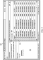
- FIG. 5 illustrates a user interface for managing organizational units in accordance with an illustrative embodiment.
- Interface 500 includes a selector 510 that allows an administrator to select between displaying all members of an organization or just those from specific organizational units within the organization.
- the administrator has selected all users within the organization. These users are displayed in a list 502 comprising user names and other identifying data within the organization. Next to each user is a selection box 504 that allows the administrator to select a user in question to add the user to a particular enterprise directory.
- Figure 6 illustrates a user interface for managing an individual user data in accordance with an illustrative embodiment.
- Interface 600 includes an identification field 602 listing the individual user in question.
- User information field 606 comprises detailed user information such as email, home address, employee identification, department, etc.
- Resource usage field 604 show how much of directory resources available to the user have been used.
- Security field 608 indicates the security settings and policies that have been set for the user.
- Field 610 indicates which groups or teams with the organization to which the user belongs.
- Figure 7 illustrates a user interface for managing teams in accordance with an illustrative embodiment.
- Interface 700 displays a profile of a group or team identified in field 710. All members assigned to the team are shown in list 702.
- a selection box 704 Next to each user is a selection box 704 that allows the administrator to select a team member to make a change such as, e.g., removing the member from the team, changing user security settings, etc.
- Interface 500 and interface 700 allow an administrator to define a team comprising a subset of user profiles selected from the HR database and select a subset of external directories that are accessible by members of the team through the LDAP interface.
- Data processing system 800 may be used to implement one or more computers and client computer system 112 in Figure 1 .
- data processing system 800 includes communications framework 802, which provides communications between processor unit 804, memory 806, persistent storage 808, communications unit 810, input/output unit 812, and display 814.
- communications framework 802 may take the form of a bus system.
- Processor unit 804 serves to execute instructions for software that may be loaded into memory 806.
- Processor unit 804 may be a number of processors, a multi-processor core, or some other type of processor, depending on the particular implementation.
- processor unit 804 comprises one or more conventional general purpose central processing units (CPUs).
- processor unit 804 comprises one or more graphical processing units (GPUs).
- Memory 806 and persistent storage 808 are examples of storage devices 816.
- a storage device is any piece of hardware that is capable of storing information, such as, for example, without limitation, at least one of data, program code in functional form, or other suitable information either on a temporary basis, a permanent basis, or both on a temporary basis and a permanent basis.
- Storage devices 816 may also be referred to as computer-readable storage devices in these illustrative examples.
- Memory 816 in these examples, may be, for example, a random access memory or any other suitable volatile or non-volatile storage device.
- Persistent storage 808 may take various forms, depending on the particular implementation.
- persistent storage 808 may contain one or more components or devices.
- persistent storage 808 may be a hard drive, a flash memory, a rewritable optical disk, a rewritable magnetic tape, or some combination of the above.
- the media used by persistent storage 808 also may be removable.
- a removable hard drive may be used for persistent storage 808.
- Communications unit 810 in these illustrative examples, provides for communications with other data processing systems or devices. In these illustrative examples, communications unit 810 is a network interface card.
- Input/output unit 812 allows for input and output of data with other devices that may be connected to data processing system 800.
- input/output unit 812 may provide a connection for user input through at least one of a keyboard, a mouse, or some other suitable input device. Further, input/output unit 812 may send output to a printer.
- Display 814 provides a mechanism to display information to a user.
- Instructions for at least one of the operating system, applications, or programs may be located in storage devices 816, which are in communication with processor unit 804 through communications framework 802.
- the processes of the different embodiments may be performed by processor unit 804 using computer-implemented instructions, which may be located in a memory, such as memory 806.
- program code computer-usable program code, or computer-readable program code that may be read and executed by a processor in processor unit 804.
- the program code in the different embodiments may be embodied on different physical or computer-readable storage media, such as memory 806 or persistent storage 808.
- Program code 818 is located in a functional form on computer-readable media 820 that is selectively removable and may be loaded onto or transferred to data processing system 800 for execution by processor unit 804.
- Program code 818 and computer-readable media 820 form computer program product 822 in these illustrative examples.
- computer-readable media 820 may be computer-readable storage media 824 or computer-readable signal media 826.
- computer-readable storage media 824 is a physical or tangible storage device used to store program code 818 rather than a medium that propagates or transmits program code 818.
- program code 818 may be transferred to data processing system 800 using computer-readable signal media 826.
- Computer-readable signal media 826 may be, for example, a propagated data signal containing program code 818.
- computer-readable signal media 826 may be at least one of an electromagnetic signal, an optical signal, or any other suitable type of signal. These signals may be transmitted over at least one of communications links, such as wireless communications links, optical fiber cable, coaxial cable, a wire, or any other suitable type of communications link.
- data processing system 800 The different components illustrated for data processing system 800 are not meant to provide architectural limitations to the manner in which different embodiments may be implemented.
- the different illustrative embodiments may be implemented in a data processing system including components in addition to or in place of those illustrated for data processing system 800.
- Other components shown in Figure 8 can be varied from the illustrative examples shown.
- the different embodiments may be implemented using any hardware device or system capable of running program code 818.
- a number means one or more.
- the phrase "at least one of”, when used with a list of items, means different combinations of one or more of the listed items may be used, and only one of each item in the list may be needed. In other words, “at least one of” means any combination of items and number of items may be used from the list, but not all of the items in the list are required.
- the item may be a particular object, a thing, or a category.
- At least one of item A, item B, or item C may include item A, item A and item B, or item C. This example also may include item A, item B, and item C or item B and item C. Of course, any combinations of these items may be present. In some illustrative examples, "at least one of” may be, for example, without limitation, two of item A; one of item B; and ten of item C; four of item B and seven of item C; or other suitable combinations.
- each block in the flowcharts or block diagrams may represent at least one of a module, a segment, a function, or a portion of an operation or step.
- one or more of the blocks may be implemented as program code.
- a component may be configured to perform the action or operation described.
- the component may have a configuration or design for a structure that provides the component an ability to perform the action or operation that is described in the illustrative examples as being performed by the component.
- different illustrative embodiments may provide different features as compared to other desirable embodiments. The embodiment or embodiments selected are chosen and described in order to best explain the principles of the embodiments, the practical application, and to enable others of ordinary skill in the art to understand the disclosure for various embodiments with various modifications as are suited to the particular use contemplated.
Landscapes
- Engineering & Computer Science (AREA)
- Business, Economics & Management (AREA)
- Computer Networks & Wireless Communication (AREA)
- Signal Processing (AREA)
- Human Resources & Organizations (AREA)
- Databases & Information Systems (AREA)
- Theoretical Computer Science (AREA)
- Physics & Mathematics (AREA)
- Data Mining & Analysis (AREA)
- Entrepreneurship & Innovation (AREA)
- Strategic Management (AREA)
- General Physics & Mathematics (AREA)
- General Engineering & Computer Science (AREA)
- Tourism & Hospitality (AREA)
- General Business, Economics & Management (AREA)
- Quality & Reliability (AREA)
- Operations Research (AREA)
- Marketing (AREA)
- Economics (AREA)
- Computer Security & Cryptography (AREA)
- Computer Hardware Design (AREA)
- Computing Systems (AREA)
- Information Retrieval, Db Structures And Fs Structures Therefor (AREA)
- Time Recorders, Dirve Recorders, Access Control (AREA)
- Storage Device Security (AREA)
Description
- The present disclosure relates generally to an improved computer system and, in particular, to synchronizing and managing enterprise data across multiple third party directories.
- An enterprise directory holds information on the resources in an enterprise. These resources can include user, groups, and hardware. Users and organizations might employ a wide variety of commoditized enterprise tools and directories to assist them in their day-to-day work, such as communications, productivity, and file management software. These different tools do not communicate with each other and might be implemented differently. All require organization data to be input, requiring the customer to set up and manage their access and entitlement across multiple systems.
- Managing multiple such tools requires regular manual updating of each system for routine organizational updates including, for example, creating new directory users when new employees are hired, removing users when employment ends, changing attributes (e.g., user name) on directory resources, and creating lists or groups of users in a directory.
-
US2003145003A1 describes a system and method which propagates change operations to data items within a metadirectory on a differential basis in order to minimize or eliminate redundant updates to attributes within data items that have not changed, as well as conserve computing resources and transmission bandwidth consumed by update activities in large organizations of data items. A best match entry in the metadirectory is selected using a weighted score process, a determination is made as to exactly which attributes are changed by the update operation, and a differential update is propagated throughout the metadirectory via direct joiner access to the data items, or through remote access such as through LDAP. -
US2012246112A1 describes a method may include storing a first database including a first plurality of user identifiers (IDs) and corresponding privileges for accessing network resources associated with an organization. The method may also include storing a second database, different than the first database, including the first plurality of user IDs. The method may also include storing a third database, different than the first database and second database, including a second plurality user IDs associated with the organization. Further, the method may include removing, from the first database, privileges associated with user IDs appearing in the second database but not in the third database. - "Oracle Fusion Middleware - Administrator's Guide for Oracle Virtual Directory" provides information on how to utilize and administer Oracle Virtual Directory in an enterprise directory infrastructure.
-
US2014156684A1 describes a lightweight directory access (LDAP) broker receives user information associated with a query for information in an LDAP repository. The query may be in an abstraction format. The LDAP broker determines a computing domain in view of the user information and retrieves a configuration file associated with the computing domain. The configuration file comprises a mapping for the query between an abstraction format and a vendor specific format. The LDAP broker converts the query to the vendor specific format in view of the mapping in the configuration file. - The invention is set out in the anexed claims.
- The novel features believed characteristic of the illustrative embodiments are set forth in the appended claims. The illustrative embodiments, however, as well as a preferred mode of use, further objectives and features thereof, will best be understood by reference to the following detailed description of an illustrative embodiment of the present disclosure when read in conjunction with the accompanying drawings, wherein:
-
Figure 1 is an illustration of a block diagram of an information environment in accordance with an illustrative embodiment; -
Figure 2 is a block diagram of a computer system for managing and synchronizing enterprise data across multiple external systems is in accordance with an illustrative embodiment; -
Figure 3 is a block diagram of data synchronization between an internal platform and external enterprise system in accordance with an illustrative embodiment; -
Figure 4 depicts a process flow for synchronizing data across multiple external systems through a LDAP interface in accordance with an illustrative embodiment; -
Figure 5 illustrates a user interface for managing organizational units in accordance with an illustrative embodiment; -
Figure 6 illustrates a user interface for managing an individual user data in accordance with an illustrative embodiment; -
Figure 7 illustrates a user interface for managing teams in accordance with an illustrative embodiment; and -
Figure 8 is an illustration of a block diagram of a data processing system in accordance with an illustrative embodiment. - The illustrative embodiments recognize and take into account one or more different considerations. For example, the illustrative embodiments recognize and take into account that organizations employing multiple external enterprise directories have to continually update and manage data across multiple systems which might be implemented differently and all require organization data. Such management across multiple systems is laborious and time consuming.
- The illustrative embodiments further recognize and take into account that manually managing and updating decentralized data across multiple systems can result in data that is inconsistent and not synchronized across these systems.
- The illustrative embodiments further recognize and take into account that time delays between employment termination and updating of directory user access creates potential securities risks to an organization.
- Illustrative embodiments provide an interface that allows users to automatically synchronize updated user and organization data across multiple external systems using a singular point of access while maintaining authorization with those external systems.
- With reference now to the figures and, in particular, with reference to
Figure 1 , an illustration of a diagram of a data processing environment is depicted in accordance with an illustrative embodiment. It should be appreciated thatFigure 1 is only provided as an illustration of one implementation and is not intended to imply any limitation with regard to the environments in which the different embodiments may be implemented. Many modifications to the depicted environments may be made. - The computer-readable program instructions may also be loaded onto a computer, a programmable data processing apparatus, or other device to cause a series of operational steps to be performed on the computer, a programmable apparatus, or other device to produce a computer implemented process, such that the instructions which execute on the computer, the programmable apparatus, or the other device implement the functions and/or acts specified in the flowchart and/or block diagram block or blocks.
-
Figure 1 depicts a pictorial representation of a network of data processing systems in which illustrative embodiments may be implemented. Networkdata processing system 100 is a network of computers in which the illustrative embodiments may be implemented. Networkdata processing system 100 containsnetwork 102, which is a medium used to provide communications links between various devices and computers connected together within networkdata processing system 100. Network 102 may include connections, such as wire, wireless communication links, or fiber optic cables. - In the depicted example,
server computer 104 andserver computer 106 connect tonetwork 102 along withstorage unit 108. In addition, client computers includeclient computer 110,client computer 112, andclient computer 114.Client computer 110,client computer 112, andclient computer 114 connect tonetwork 102. These connections can be wireless or wired connections depending on the implementation.Client computer 110,client computer 112, andclient computer 114 may be, for example, personal computers or network computers. In the depicted example,server computer 104 provides information, such as boot files, operating system images, and applications toclient computer 110,client computer 112, andclient computer 114.Client computer 110,client computer 112, andclient computer 114 are clients to servercomputer 104 in this example. Networkdata processing system 100 may include additional server computers, client computers, and other devices not shown. - Program code located in network
data processing system 100 may be stored on a computer-recordable storage medium and downloaded to a data processing system or other device for use. For example, the program code may be stored on a computer-recordable storage medium onserver computer 104 and downloaded toclient computer 110 overnetwork 102 for use onclient computer 110. - In the depicted example, network
data processing system 100 is the Internet withnetwork 102 representing a worldwide collection of networks and gateways that use the Transmission Control Protocol/Internet Protocol (TCP/IP) suite of protocols to communicate with one another. At the heart of the Internet is a backbone of high-speed data communication lines between major nodes or host computers consisting of thousands of commercial, governmental, educational, and other computer systems that route data and messages. Of course, networkdata processing system 100 also may be implemented as a number of different types of networks, such as, for example, an intranet, a local area network (LAN), or a wide area network (WAN).Figure 1 is intended as an example, and not as an architectural limitation for the different illustrative embodiments. - The illustration of network
data processing system 100 is not meant to limit the manner in which other illustrative embodiments can be implemented. For example, other client computers may be used in addition to or in place ofclient computer 110,client computer 112, andclient computer 114 as depicted inFigure 1 . For example,client computer 110,client computer 112, andclient computer 114 may include a tablet computer, a laptop computer, a bus with a vehicle computer, and other suitable types of clients. - In the illustrative examples, the hardware may take the form of a circuit system, an integrated circuit, an application-specific integrated circuit (ASIC), a programmable logic device, or some other suitable type of hardware configured to perform a number of operations. With a programmable logic device, the device may be configured to perform the number of operations. The device may be reconfigured at a later time or may be permanently configured to perform the number of operations. Programmable logic devices include, for example, a programmable logic array, programmable array logic, a field programmable logic array, a field programmable gate array, and other suitable hardware devices. Additionally, the processes may be implemented in organic components integrated with inorganic components and may be comprised entirely of organic components, excluding a human being. For example, the processes may be implemented as circuits in organic semiconductors.
- Turning to
Figure 2 , a block diagram of a computer system for managing and synchronizing enterprise data across multiple external systems is depicted in accordance with an illustrative embodiment.System 200 comprises aninternal system 202 such as, for example, a human resources (HR) database or similar platform. Through a lightweight directory access protocol (LDAP)interface 240, theinternal system 202 can populate, update, and synchronize enterprise data across multipleexternal systems 250. - The
internal system 202 can be an HR platform or database with itsown communications protocol 204. Theinternal system 202 can havemultiple users 210 can be individuals or organizations. In an illustrative example, the user 220 amongusers 210 is an organization that hasmultiple employees 224. Eachemployee 226 amongemployees 224 has a set ofattributes 228. These attributes can include personal identifying information as well as position and responsibilities within the user organization 220, including access privileges to enterprises services such asexternal systems 250. - Groups of employees within a user organization 220 can be organized into
different teams 230. Eachteam 232 withinteams 230 has itsown attributes 234, which define the membership and function of the team within the organization including access privileges of the team to enterprise services such asexternal systems 250. Access privileges to external systems listed in theattributes 228 of an employee can depend from theattributes 234 of ateam 232 to which the employee belongs. Furthermore, anemployee 226 might belong to multiple teams withinteam 230. - The
LDAP interface 240 provides a singular point of access forusers 210 ofinternal system 202 to manage, update, and synchronize enterprise data across multipleexternal systems 250 through the Transmission Control Protocol/Internet Protocol (TCP/IP) protocol stack.LDAP 240 interface serves as a system of record data source - LDAP is a request-response application protocol for accessing and maintaining distributed directory services. The
LDAP interface 240 serves as a central repository for authorization attributes 244, including usernames and passwords and other access credentials.LDAP interface 240 provides aprotocol transition 242 between theprotocol 204 ofinternal system 202 andprotocol 256 ofexternal system 252, which might differ from the protocols from other systems amongexternal systems 250. -
LDAP interface 240 acts as a layer over theinternal HR system 202 that acts as a proxy for requests between theinternal system 202 andexternal systems 250.LDAP interface 240 presents data on theexternal systems 250 as close to the original as possible. By maintaining authorization attributes andcredentials 244 on an on-demand basis,LDAP interface 240 enabling the HR system to be the source of truth for theexternal systems 250 and savingusers 210 from having to continually log into theexternal systems 250 or being timed out of a session. -
External systems 250 comprise third party enterprise directories providing a plurality of services tousers 210.External systems 250 can be heterogeneous directories, which can be implemented differently from each other. Eachexternal system 252 withinexternal systems 250 hasunique functions 254. Examples offunctions 254 include communications (e.g., email and messaging), productivity, and file management. External system also has its own protocol, which can be different from protocols from the other external systems. -
External system 252 includes users 258. Users 258 can include individuals, organizations, or teams within organizations.User 260 among users 258 hasdata 262 stored on theexternal system 252.User data 252 is maintained and synchronized across theexternal directories 250 according to business logic-specified directory tools associated with the external directories. -
LDAP interface 240 maps users 258 listed in theexternal directories 250 tousers 210 listed in theinternal HR database 202.LDAP interface 240 can also map employee groupings (teams) in theexternal directories 250 toteams 230 listed in theHR database 202. -
Figure 3 is a block diagram of data synchronization between an internal platform and external enterprise system in accordance with an illustrative embodiment. This diagram illustrates how the LDAP interface handles the protocol transition between external and internal systems. - The
internal HR system 310 connects to theLDAP Service 320 throughTCP 312 and hypertext transfer protocol (HTTP) 314. Representation state transfer/JavaScript Object Notation (REST/JSON) 316 provides stateless browser-to-server communications to provide interoperability between systems. - The
LDAP service 320 uses theLDAP protocol 324 built on abstract syntax notation one (ASN.1) 326 to synchronize data received frominternal HR system 310 with external system throughTCP protocol 322. -
Figure 4 depicts a process flow for synchronizing data across multiple external systems through a LDAP interface in accordance with an illustrative embodiment.Process 400 begins with an LDAP bind operation which authenticates the client system to the LDAP interface (step 402). After successful authentication, the LDAP interface institutes throttling to limit how fast data will be transferred through the service, which prevents the service from using all available bandwidth (step 404). - The interface then parses a request from the client and initiates an LDAP bind with the external directories (step 408) and prepares the LDAP root directory (step 410) to access the
data cache 412 in an external directory. The LDAP interface submits an LDAP query to an external directory (step 416). - In response to the LDAP query, the external directory searches for data in the data cache 412 (step 416). If information from the client request is not found in the external direction, the external directory adds the missing data to the cache (step 418) and prepares a response (step 420). A reply is then sent to the LDAP interface denoting that the external directory has been updated in accordance with the client request (step 422).
- If there is no more new data to update and synchronize across the external directories, the LDAP interface unbinds from the client (step 424), the process ends.
-
Figure 5 illustrates a user interface for managing organizational units in accordance with an illustrative embodiment.Interface 500 includes aselector 510 that allows an administrator to select between displaying all members of an organization or just those from specific organizational units within the organization. - In the example shown in
Figure 5 , the administrator has selected all users within the organization. These users are displayed in alist 502 comprising user names and other identifying data within the organization. Next to each user is aselection box 504 that allows the administrator to select a user in question to add the user to a particular enterprise directory. -
Figure 6 illustrates a user interface for managing an individual user data in accordance with an illustrative embodiment.Interface 600 includes anidentification field 602 listing the individual user in question.User information field 606 comprises detailed user information such as email, home address, employee identification, department, etc. -
Resource usage field 604 show how much of directory resources available to the user have been used.Security field 608 indicates the security settings and policies that have been set for the user.Field 610 indicates which groups or teams with the organization to which the user belongs. -
Figure 7 illustrates a user interface for managing teams in accordance with an illustrative embodiment.Interface 700 displays a profile of a group or team identified infield 710. All members assigned to the team are shown inlist 702. Next to each user is aselection box 704 that allows the administrator to select a team member to make a change such as, e.g., removing the member from the team, changing user security settings, etc. -
Interface 500 andinterface 700 allow an administrator to define a team comprising a subset of user profiles selected from the HR database and select a subset of external directories that are accessible by members of the team through the LDAP interface. - Turning now to
Figure 8 , an illustration of a block diagram of a data processing system is depicted in accordance with an illustrative embodiment.Data processing system 800 may be used to implement one or more computers andclient computer system 112 inFigure 1 . In this illustrative example,data processing system 800 includescommunications framework 802, which provides communications betweenprocessor unit 804,memory 806,persistent storage 808,communications unit 810, input/output unit 812, anddisplay 814. In this example,communications framework 802 may take the form of a bus system. -
Processor unit 804 serves to execute instructions for software that may be loaded intomemory 806.Processor unit 804 may be a number of processors, a multi-processor core, or some other type of processor, depending on the particular implementation. In an embodiment,processor unit 804 comprises one or more conventional general purpose central processing units (CPUs). In an alternate embodiment,processor unit 804 comprises one or more graphical processing units (GPUs). -
Memory 806 andpersistent storage 808 are examples ofstorage devices 816. A storage device is any piece of hardware that is capable of storing information, such as, for example, without limitation, at least one of data, program code in functional form, or other suitable information either on a temporary basis, a permanent basis, or both on a temporary basis and a permanent basis.Storage devices 816 may also be referred to as computer-readable storage devices in these illustrative examples.Memory 816, in these examples, may be, for example, a random access memory or any other suitable volatile or non-volatile storage device.Persistent storage 808 may take various forms, depending on the particular implementation. - For example,
persistent storage 808 may contain one or more components or devices. For example,persistent storage 808 may be a hard drive, a flash memory, a rewritable optical disk, a rewritable magnetic tape, or some combination of the above. The media used bypersistent storage 808 also may be removable. For example, a removable hard drive may be used forpersistent storage 808.Communications unit 810, in these illustrative examples, provides for communications with other data processing systems or devices. In these illustrative examples,communications unit 810 is a network interface card. - Input/
output unit 812 allows for input and output of data with other devices that may be connected todata processing system 800. For example, input/output unit 812 may provide a connection for user input through at least one of a keyboard, a mouse, or some other suitable input device. Further, input/output unit 812 may send output to a printer.Display 814 provides a mechanism to display information to a user. - Instructions for at least one of the operating system, applications, or programs may be located in
storage devices 816, which are in communication withprocessor unit 804 throughcommunications framework 802. The processes of the different embodiments may be performed byprocessor unit 804 using computer-implemented instructions, which may be located in a memory, such asmemory 806. - These instructions are referred to as program code, computer-usable program code, or computer-readable program code that may be read and executed by a processor in
processor unit 804. The program code in the different embodiments may be embodied on different physical or computer-readable storage media, such asmemory 806 orpersistent storage 808. -
Program code 818 is located in a functional form on computer-readable media 820 that is selectively removable and may be loaded onto or transferred todata processing system 800 for execution byprocessor unit 804.Program code 818 and computer-readable media 820 formcomputer program product 822 in these illustrative examples. In one example, computer-readable media 820 may be computer-readable storage media 824 or computer-readable signal media 826. - In these illustrative examples, computer-
readable storage media 824 is a physical or tangible storage device used to storeprogram code 818 rather than a medium that propagates or transmitsprogram code 818. Alternatively,program code 818 may be transferred todata processing system 800 using computer-readable signal media 826. - Computer-
readable signal media 826 may be, for example, a propagated data signal containingprogram code 818. For example, computer-readable signal media 826 may be at least one of an electromagnetic signal, an optical signal, or any other suitable type of signal. These signals may be transmitted over at least one of communications links, such as wireless communications links, optical fiber cable, coaxial cable, a wire, or any other suitable type of communications link. - The different components illustrated for
data processing system 800 are not meant to provide architectural limitations to the manner in which different embodiments may be implemented. The different illustrative embodiments may be implemented in a data processing system including components in addition to or in place of those illustrated fordata processing system 800. Other components shown inFigure 8 can be varied from the illustrative examples shown. The different embodiments may be implemented using any hardware device or system capable of runningprogram code 818. - As used herein, the phrase "a number" means one or more. The phrase "at least one of", when used with a list of items, means different combinations of one or more of the listed items may be used, and only one of each item in the list may be needed. In other words, "at least one of" means any combination of items and number of items may be used from the list, but not all of the items in the list are required. The item may be a particular object, a thing, or a category.
- For example, without limitation, "at least one of item A, item B, or item C" may include item A, item A and item B, or item C. This example also may include item A, item B, and item C or item B and item C. Of course, any combinations of these items may be present. In some illustrative examples, "at least one of" may be, for example, without limitation, two of item A; one of item B; and ten of item C; four of item B and seven of item C; or other suitable combinations.
- The flowcharts and block diagrams in the different depicted embodiments illustrate the architecture, functionality, and operation of some possible implementations of apparatuses and methods in an illustrative embodiment. In this regard, each block in the flowcharts or block diagrams may represent at least one of a module, a segment, a function, or a portion of an operation or step. For example, one or more of the blocks may be implemented as program code.
- The description of the different illustrative embodiments has been presented for purposes of illustration and description and is not intended to be exhaustive or limited to the embodiments in the form disclosed. The different illustrative examples describe components that perform actions or operations. In an illustrative embodiment, a component may be configured to perform the action or operation described. For example, the component may have a configuration or design for a structure that provides the component an ability to perform the action or operation that is described in the illustrative examples as being performed by the component. Further, different illustrative embodiments may provide different features as compared to other desirable embodiments. The embodiment or embodiments selected are chosen and described in order to best explain the principles of the embodiments, the practical application, and to enable others of ordinary skill in the art to understand the disclosure for various embodiments with various modifications as are suited to the particular use contemplated.
Claims (15)
- A computer-implemented method for managing enterprise data, the method comprising:creating, by a number of processors, a human resources, HR, database;creating, by the number of processors, a lightweight directory access protocol, LDAP, interface in communication with the HR database and a number of third party heterogeneous external directories, wherein the HR database is the source of truth for the external directories,wherein each external directory has a respective protocol that differs from protocols of other heterogenous external directories,wherein the LDAP interface serves as a proxy for requests between the number of third party heterogenous external directories and the HR database,wherein the LDAP interface maintains authorization credentials with the number of third party heterogenous external directories;managing and synchronizing, by the number of processors, user data through the LDAP interface across the number of third party heterogeneous external directories using the LDAP protocol, wherein the LDAP interface:authenticates a client system using an LDAP bind operation,parses a request from the client,initiates an LDAP bind operation with the number of third party heterogenous external directories,prepares the LDAP root directory to access the data cache in one of the external directories,submits an LDAP query to the external directory;wherein the external directory, in response to said query, searches for client request data in the data cache and, if not found, adds the missing data to the data cache, and sends a response denoting that the external directory has been updated;wherein the LDAP interface unbinds from the client when there is no more data to update and synchronize across the external directories.
- The method of claim 1, wherein user data is maintained and synchronized across the number of external directories according to business logic-specified directory tools associated with the number of external directories.
- The method of claim 1, wherein the LDAP interface serves as a system of record data source.
- The method of claim 1, further comprising:
mapping users listed in the external directories to users listed in the HR database. - The method of claim 1, further comprising:
mapping employee groupings in the external directories to teams listed in the HR database. - The method of claim 1, further comprising:defining a team comprising a subset of user profiles selected from among a number of user profiles in the HR database; andselecting a subset of external directories from among the number of external directories that are accessible by members of the team through the LDAP interface.
- The method of claim 1, wherein the LDAP interface maintains the authorization credentials with the external directories on an on-demand basis.
- The method of claim 1, wherein the LDAP interface provides a protocol transition between the HR database and the number of external directories.
- The method of claim 1, wherein a user comprises one of:an individual user;an organization; ora team of individuals.
- A system for managing enterprise data, the system comprising:a bus system;a storage device connected to the bus system, wherein the storage device stores program instructions; anda number of processors connected to the bus system, wherein the number of processors execute the program instructions to:create a human resources, HR, database; create a lightweight directory access protocol, LDAP, interface in communication with the HR database and a number of third party heterogeneous external directories,wherein the HR database is the source of truth for the external directories,wherein each external directory has a respective protocol that differs from protocols of other heterogenous external directories,wherein the LDAP interface serves as a proxy for requests between the number of third party heterogenous external directories and the HR database,wherein the LDAP interface maintains authorization credentials with the number of third party heterogenous external directories;manage and synchronize user data through the LDAP interface across the number of third party heterogeneous external directories using the LDAP protocol, wherein the LDAP interface:authenticates a client system using an LDAP bind operation,parses a request from the client, initiates an LDAP bind operation with the number of third party heterogenous external directories,prepares the LDAP root directory to access the data cache in one of the external directories,submits an LDAP query to the external directory;wherein the external directory, in response to said query, searches for client request data in the data cache and, if not found, adds the missing data to the data cache, and sends a response denoting that the external directory has been updated;wherein the LDAP interface unbinds from the client when there is no more data to update and synchronize across the external directories.
- The system of claim 10, wherein the LDAP interface maintains the authorization credentials with the external directories on an on-demand basis.
- The system of claim 10, wherein the LDAP interface provides a protocol transition between the HR database and the number of external directories.
- A computer program product for managing enterprise data, the computer program product comprising:
a non-volatile computer readable storage medium having program instructions embodied therewith, the program instructions executable by a number of processors to cause the computer to perform the steps of:creating, by a number of processors, a human resources, HR, database;creating, by the number of processors, a lightweight directory access protocol, LDAP, interface in communication with the HR database and a number of third party heterogeneous external directories, wherein the HR database is the source of truth for the external directories,wherein each external directory has a respective protocol that differs from protocols of other heterogenous external directories,wherein the LDAP interface serves as a proxy for requests between the number of third party heterogenous external directories and the HR database,wherein the LDAP interface maintains authorization credentials with the number of third party heterogenous external directories;managing and synchronizing, by the number of processors, user data through the LDAP interface across the number of third party heterogeneous external directories using the LDAP protocol, wherein the LDAP interface:authenticates a client system using an LDAP bind operation,parses a request from the client, initiates an LDAP bind operation with the number of third party heterogenous external directories,prepares the LDAP root directory to access the data cache in one of the external directories,submits an LDAP query to the external directory;wherein the external directory, in response to said query, searches for client request data in the data cache and, if not found, adds the missing data to the data cache, and sends a response denoting that the external directory has been updated;wherein the LDAP interface unbinds from the client when there is no more data to update and synchronize across the external directories. interface maintains authorization credentials with the number of third party heterogenous external directories. - The computer program product according to claim 13, wherein the LDAP interface maintains the authorization credentials with the external directories on an on-demand basis.
- The computer program product according to claim 13, wherein the LDAP interface provides a protocol transition between the HR database and the number of external directories.
Priority Applications (1)
| Application Number | Priority Date | Filing Date | Title |
|---|---|---|---|
| EP25177627.4A EP4582971A3 (en) | 2019-03-07 | 2020-02-26 | Industry standard interface for maintenance of enterprise systems |
Applications Claiming Priority (2)
| Application Number | Priority Date | Filing Date | Title |
|---|---|---|---|
| US16/295,313 US12013877B2 (en) | 2019-03-07 | 2019-03-07 | Industry standard interface for maintenance of enterprise systems |
| PCT/US2020/019891 WO2020180561A1 (en) | 2019-03-07 | 2020-02-26 | Industry standard interface for maintenance of enterprise systems |
Related Child Applications (1)
| Application Number | Title | Priority Date | Filing Date |
|---|---|---|---|
| EP25177627.4A Division EP4582971A3 (en) | 2019-03-07 | 2020-02-26 | Industry standard interface for maintenance of enterprise systems |
Publications (3)
| Publication Number | Publication Date |
|---|---|
| EP3935483A1 EP3935483A1 (en) | 2022-01-12 |
| EP3935483A4 EP3935483A4 (en) | 2022-12-14 |
| EP3935483B1 true EP3935483B1 (en) | 2025-05-21 |
Family
ID=72336431
Family Applications (2)
| Application Number | Title | Priority Date | Filing Date |
|---|---|---|---|
| EP20766534.0A Active EP3935483B1 (en) | 2019-03-07 | 2020-02-26 | Industry standard interface for maintenance of enterprise systems |
| EP25177627.4A Pending EP4582971A3 (en) | 2019-03-07 | 2020-02-26 | Industry standard interface for maintenance of enterprise systems |
Family Applications After (1)
| Application Number | Title | Priority Date | Filing Date |
|---|---|---|---|
| EP25177627.4A Pending EP4582971A3 (en) | 2019-03-07 | 2020-02-26 | Industry standard interface for maintenance of enterprise systems |
Country Status (5)
| Country | Link |
|---|---|
| US (2) | US12013877B2 (en) |
| EP (2) | EP3935483B1 (en) |
| CA (1) | CA3125640A1 (en) |
| ES (1) | ES3047130T3 (en) |
| WO (1) | WO2020180561A1 (en) |
Family Cites Families (17)
| Publication number | Priority date | Publication date | Assignee | Title |
|---|---|---|---|---|
| US6345266B1 (en) * | 1998-12-23 | 2002-02-05 | Novell, Inc. | Predicate indexing for locating objects in a distributed directory |
| US7185361B1 (en) | 2000-01-31 | 2007-02-27 | Secure Computing Corporation | System, method and computer program product for authenticating users using a lightweight directory access protocol (LDAP) directory server |
| WO2001067309A2 (en) | 2000-03-03 | 2001-09-13 | Radiant Logic, Inc. | System and method for providing access to databases via directories and other hierarchical structures and interfaces |
| US7107297B2 (en) | 2002-01-10 | 2006-09-12 | International Business Machines Corporation | System and method for metadirectory differential updates among constituent heterogeneous data sources |
| CN1653783B (en) * | 2002-03-20 | 2010-06-16 | 捷讯研究有限公司 | Systems and methods for mobile lightweight password directory access |
| US20050096048A1 (en) * | 2003-10-30 | 2005-05-05 | Cellco Partnership | Optimized network employing seamless and single sign on capabilities for users accessing data applications on different networks |
| US7844710B2 (en) * | 2007-02-27 | 2010-11-30 | Novell, Inc. | Proxy caching for directory services |
| US20090276297A1 (en) | 2008-05-05 | 2009-11-05 | Sap Ag | Method and system for reviewing and managing employees |
| US20100064353A1 (en) * | 2008-09-09 | 2010-03-11 | Facetime Communications, Inc. | User Mapping Mechanisms |
| US8706692B1 (en) * | 2010-02-12 | 2014-04-22 | Citibank, N.A. | Corporate infrastructure management system |
| US8671073B2 (en) * | 2011-03-23 | 2014-03-11 | Verizon Patent And Licensing Inc. | Synchronizing human resource database with authorization database |
| US9143498B2 (en) * | 2012-08-30 | 2015-09-22 | Aerohive Networks, Inc. | Internetwork authentication |
| US9063971B2 (en) | 2012-12-03 | 2015-06-23 | Red Hat Israel, Ltd. | Schema and query abstraction for different LDAP service providers |
| US20150006415A1 (en) | 2013-06-27 | 2015-01-01 | Successfactors, Inc. | Systems and Methods for Displaying and Analyzing Employee History Data |
| US20160098666A1 (en) | 2014-10-03 | 2016-04-07 | Soren Hojby | Transferring Employees in Operational Workforce Planning |
| US10459944B2 (en) | 2016-04-14 | 2019-10-29 | Microsoft Technology Licensing, Llc | Synchronizing hierarchical information while preserving team structure |
| US10986081B1 (en) * | 2017-09-28 | 2021-04-20 | Amazon Technologies, Inc. | Cross-organization registration for single sign-on |
-
2019
- 2019-03-07 US US16/295,313 patent/US12013877B2/en active Active
-
2020
- 2020-02-26 WO PCT/US2020/019891 patent/WO2020180561A1/en not_active Ceased
- 2020-02-26 CA CA3125640A patent/CA3125640A1/en active Pending
- 2020-02-26 ES ES20766534T patent/ES3047130T3/en active Active
- 2020-02-26 EP EP20766534.0A patent/EP3935483B1/en active Active
- 2020-02-26 EP EP25177627.4A patent/EP4582971A3/en active Pending
-
2024
- 2024-06-17 US US18/745,629 patent/US20250013665A1/en active Pending
Also Published As
| Publication number | Publication date |
|---|---|
| ES3047130T3 (en) | 2025-12-03 |
| US20200285656A1 (en) | 2020-09-10 |
| EP4582971A3 (en) | 2025-10-08 |
| CA3125640A1 (en) | 2020-09-10 |
| EP4582971A2 (en) | 2025-07-09 |
| EP3935483A4 (en) | 2022-12-14 |
| EP3935483A1 (en) | 2022-01-12 |
| US12013877B2 (en) | 2024-06-18 |
| US20250013665A1 (en) | 2025-01-09 |
| WO2020180561A1 (en) | 2020-09-10 |
Similar Documents
| Publication | Publication Date | Title |
|---|---|---|
| JP7599532B2 (en) | DETECTING AND RESOLVING DATA REPLICATION CONFLICT IN A MULTI-TENANT IDENTITY CLOUD SERVICE - Patent application | |
| CN111801923B (en) | Replication of resource type and schema metadata for multi-tenant identity cloud services | |
| EP3695563B1 (en) | Apparatus, method, and computing device for selectively granting permissions to group-based objects in a group-based communication system | |
| US10705823B2 (en) | Application templates and upgrade framework for a multi-tenant identity cloud service | |
| CN108701182B (en) | Data management for multi-tenant identity cloud services | |
| US11308132B2 (en) | Reference attributes for related stored objects in a multi-tenant cloud service | |
| JP7018437B2 (en) | Multi-tenant identity and data security management Tenant and service management for cloud services | |
| US20200274900A1 (en) | Automatic API Document Generation From SCIM Metadata | |
| US20180083835A1 (en) | Application management for a multi-tenant identity cloud service | |
| US9734466B2 (en) | Multi-tenancy engine | |
| US8103673B2 (en) | Systems and methods for provisioning content from multiple sources to a computing device | |
| US8255507B2 (en) | Active directory object management methods and systems | |
| US10091123B2 (en) | System and user interface for coordinating distributed workflow between multiple computing systems | |
| JP7336602B2 (en) | A communication device configured to manage user-specific queries and render a user-specific interface in a group-based communication system | |
| US11582138B2 (en) | Configurable system for resolving requests received from multiple client devices in a network system | |
| US11263334B2 (en) | Method and system for natively accessing enterprise data according to an identified view context | |
| US10764399B2 (en) | Customized web services gateway | |
| US10552798B2 (en) | Abstraction services for productivity servers | |
| US20250013665A1 (en) | Industry standard interface for maintenance of enterprise systems | |
| JP2001216267A (en) | Information provision control system, information provision control method, and recording medium therefor | |
| Kim et al. | A web-based monitoring system of network security functions in blockchain-based cloud security systems | |
| US20140298182A1 (en) | Centralized administration tool for operating with existing host system having non-centralized administrative functions | |
| Ranjini et al. | PRS Generic Data Store Service | |
| Guerrero | Security model in XSA | |
| Ramey | Oracle Identity and Access Management Suite Overview |
Legal Events
| Date | Code | Title | Description |
|---|---|---|---|
| STAA | Information on the status of an ep patent application or granted ep patent |
Free format text: STATUS: THE INTERNATIONAL PUBLICATION HAS BEEN MADE |
|
| PUAI | Public reference made under article 153(3) epc to a published international application that has entered the european phase |
Free format text: ORIGINAL CODE: 0009012 |
|
| STAA | Information on the status of an ep patent application or granted ep patent |
Free format text: STATUS: REQUEST FOR EXAMINATION WAS MADE |
|
| 17P | Request for examination filed |
Effective date: 20210826 |
|
| AK | Designated contracting states |
Kind code of ref document: A1 Designated state(s): AL AT BE BG CH CY CZ DE DK EE ES FI FR GB GR HR HU IE IS IT LI LT LU LV MC MK MT NL NO PL PT RO RS SE SI SK SM TR |
|
| DAV | Request for validation of the european patent (deleted) | ||
| DAX | Request for extension of the european patent (deleted) | ||
| RAP3 | Party data changed (applicant data changed or rights of an application transferred) |
Owner name: ADP, INC. |
|
| A4 | Supplementary search report drawn up and despatched |
Effective date: 20221115 |
|
| RIC1 | Information provided on ipc code assigned before grant |
Ipc: G06F 16/25 20190101ALI20221109BHEP Ipc: G06F 3/048 20130101AFI20221109BHEP |
|
| GRAP | Despatch of communication of intention to grant a patent |
Free format text: ORIGINAL CODE: EPIDOSNIGR1 |
|
| STAA | Information on the status of an ep patent application or granted ep patent |
Free format text: STATUS: GRANT OF PATENT IS INTENDED |
|
| INTG | Intention to grant announced |
Effective date: 20241211 |
|
| GRAS | Grant fee paid |
Free format text: ORIGINAL CODE: EPIDOSNIGR3 |
|
| GRAA | (expected) grant |
Free format text: ORIGINAL CODE: 0009210 |
|
| STAA | Information on the status of an ep patent application or granted ep patent |
Free format text: STATUS: THE PATENT HAS BEEN GRANTED |
|
| AK | Designated contracting states |
Kind code of ref document: B1 Designated state(s): AL AT BE BG CH CY CZ DE DK EE ES FI FR GB GR HR HU IE IS IT LI LT LU LV MC MK MT NL NO PL PT RO RS SE SI SK SM TR |
|
| REG | Reference to a national code |
Ref country code: GB Ref legal event code: FG4D |
|
| REG | Reference to a national code |
Ref country code: CH Ref legal event code: EP |
|
| P01 | Opt-out of the competence of the unified patent court (upc) registered |
Free format text: CASE NUMBER: APP_21676/2025 Effective date: 20250505 |
|
| REG | Reference to a national code |
Ref country code: DE Ref legal event code: R096 Ref document number: 602020051661 Country of ref document: DE |
|
| REG | Reference to a national code |
Ref country code: IE Ref legal event code: FG4D |
|
| REG | Reference to a national code |
Ref country code: NL Ref legal event code: FP |
|
| PG25 | Lapsed in a contracting state [announced via postgrant information from national office to epo] |
Ref country code: PT Free format text: LAPSE BECAUSE OF FAILURE TO SUBMIT A TRANSLATION OF THE DESCRIPTION OR TO PAY THE FEE WITHIN THE PRESCRIBED TIME-LIMIT Effective date: 20250922 Ref country code: FI Free format text: LAPSE BECAUSE OF FAILURE TO SUBMIT A TRANSLATION OF THE DESCRIPTION OR TO PAY THE FEE WITHIN THE PRESCRIBED TIME-LIMIT Effective date: 20250521 |
|
| REG | Reference to a national code |
Ref country code: LT Ref legal event code: MG9D |
|
| PG25 | Lapsed in a contracting state [announced via postgrant information from national office to epo] |
Ref country code: GR Free format text: LAPSE BECAUSE OF FAILURE TO SUBMIT A TRANSLATION OF THE DESCRIPTION OR TO PAY THE FEE WITHIN THE PRESCRIBED TIME-LIMIT Effective date: 20250822 Ref country code: NO Free format text: LAPSE BECAUSE OF FAILURE TO SUBMIT A TRANSLATION OF THE DESCRIPTION OR TO PAY THE FEE WITHIN THE PRESCRIBED TIME-LIMIT Effective date: 20250821 |
|
| PG25 | Lapsed in a contracting state [announced via postgrant information from national office to epo] |
Ref country code: PL Free format text: LAPSE BECAUSE OF FAILURE TO SUBMIT A TRANSLATION OF THE DESCRIPTION OR TO PAY THE FEE WITHIN THE PRESCRIBED TIME-LIMIT Effective date: 20250521 |
|
| PG25 | Lapsed in a contracting state [announced via postgrant information from national office to epo] |
Ref country code: BG Free format text: LAPSE BECAUSE OF FAILURE TO SUBMIT A TRANSLATION OF THE DESCRIPTION OR TO PAY THE FEE WITHIN THE PRESCRIBED TIME-LIMIT Effective date: 20250521 |
|
| PG25 | Lapsed in a contracting state [announced via postgrant information from national office to epo] |
Ref country code: HR Free format text: LAPSE BECAUSE OF FAILURE TO SUBMIT A TRANSLATION OF THE DESCRIPTION OR TO PAY THE FEE WITHIN THE PRESCRIBED TIME-LIMIT Effective date: 20250521 |
|
| PG25 | Lapsed in a contracting state [announced via postgrant information from national office to epo] |
Ref country code: RS Free format text: LAPSE BECAUSE OF FAILURE TO SUBMIT A TRANSLATION OF THE DESCRIPTION OR TO PAY THE FEE WITHIN THE PRESCRIBED TIME-LIMIT Effective date: 20250821 |
|
| PG25 | Lapsed in a contracting state [announced via postgrant information from national office to epo] |
Ref country code: IS Free format text: LAPSE BECAUSE OF FAILURE TO SUBMIT A TRANSLATION OF THE DESCRIPTION OR TO PAY THE FEE WITHIN THE PRESCRIBED TIME-LIMIT Effective date: 20250921 |
|
| PG25 | Lapsed in a contracting state [announced via postgrant information from national office to epo] |
Ref country code: LV Free format text: LAPSE BECAUSE OF FAILURE TO SUBMIT A TRANSLATION OF THE DESCRIPTION OR TO PAY THE FEE WITHIN THE PRESCRIBED TIME-LIMIT Effective date: 20250521 |
|
| REG | Reference to a national code |
Ref country code: ES Ref legal event code: FG2A Ref document number: 3047130 Country of ref document: ES Kind code of ref document: T3 Effective date: 20251203 |
|
| REG | Reference to a national code |
Ref country code: AT Ref legal event code: MK05 Ref document number: 1797309 Country of ref document: AT Kind code of ref document: T Effective date: 20250521 |
|
| PG25 | Lapsed in a contracting state [announced via postgrant information from national office to epo] |
Ref country code: SM Free format text: LAPSE BECAUSE OF FAILURE TO SUBMIT A TRANSLATION OF THE DESCRIPTION OR TO PAY THE FEE WITHIN THE PRESCRIBED TIME-LIMIT Effective date: 20250521 Ref country code: DK Free format text: LAPSE BECAUSE OF FAILURE TO SUBMIT A TRANSLATION OF THE DESCRIPTION OR TO PAY THE FEE WITHIN THE PRESCRIBED TIME-LIMIT Effective date: 20250521 Ref country code: AT Free format text: LAPSE BECAUSE OF FAILURE TO SUBMIT A TRANSLATION OF THE DESCRIPTION OR TO PAY THE FEE WITHIN THE PRESCRIBED TIME-LIMIT Effective date: 20250521 |
|
| PG25 | Lapsed in a contracting state [announced via postgrant information from national office to epo] |
Ref country code: CZ Free format text: LAPSE BECAUSE OF FAILURE TO SUBMIT A TRANSLATION OF THE DESCRIPTION OR TO PAY THE FEE WITHIN THE PRESCRIBED TIME-LIMIT Effective date: 20250521 |
|
| PG25 | Lapsed in a contracting state [announced via postgrant information from national office to epo] |
Ref country code: EE Free format text: LAPSE BECAUSE OF FAILURE TO SUBMIT A TRANSLATION OF THE DESCRIPTION OR TO PAY THE FEE WITHIN THE PRESCRIBED TIME-LIMIT Effective date: 20250521 |
|
| PG25 | Lapsed in a contracting state [announced via postgrant information from national office to epo] |
Ref country code: SK Free format text: LAPSE BECAUSE OF FAILURE TO SUBMIT A TRANSLATION OF THE DESCRIPTION OR TO PAY THE FEE WITHIN THE PRESCRIBED TIME-LIMIT Effective date: 20250521 Ref country code: RO Free format text: LAPSE BECAUSE OF FAILURE TO SUBMIT A TRANSLATION OF THE DESCRIPTION OR TO PAY THE FEE WITHIN THE PRESCRIBED TIME-LIMIT Effective date: 20250521 |
|
| PG25 | Lapsed in a contracting state [announced via postgrant information from national office to epo] |
Ref country code: IT Free format text: LAPSE BECAUSE OF FAILURE TO SUBMIT A TRANSLATION OF THE DESCRIPTION OR TO PAY THE FEE WITHIN THE PRESCRIBED TIME-LIMIT Effective date: 20250521 |
|
| PGFP | Annual fee paid to national office [announced via postgrant information from national office to epo] |
Ref country code: NL Payment date: 20260121 Year of fee payment: 7 |
|
| REG | Reference to a national code |
Ref country code: DE Ref legal event code: R097 Ref document number: 602020051661 Country of ref document: DE |
|
| PLBE | No opposition filed within time limit |
Free format text: ORIGINAL CODE: 0009261 |
|
| STAA | Information on the status of an ep patent application or granted ep patent |
Free format text: STATUS: NO OPPOSITION FILED WITHIN TIME LIMIT |
|
| REG | Reference to a national code |
Ref country code: CH Ref legal event code: L10 Free format text: ST27 STATUS EVENT CODE: U-0-0-L10-L00 (AS PROVIDED BY THE NATIONAL OFFICE) Effective date: 20260402 |
|
| PGFP | Annual fee paid to national office [announced via postgrant information from national office to epo] |
Ref country code: GB Payment date: 20260123 Year of fee payment: 7 |
|
| PGFP | Annual fee paid to national office [announced via postgrant information from national office to epo] |
Ref country code: ES Payment date: 20260302 Year of fee payment: 7 |
|
| PGFP | Annual fee paid to national office [announced via postgrant information from national office to epo] |
Ref country code: DE Payment date: 20260121 Year of fee payment: 7 |
|
| PGFP | Annual fee paid to national office [announced via postgrant information from national office to epo] |
Ref country code: FR Payment date: 20260121 Year of fee payment: 7 |
|
| 26N | No opposition filed |
Effective date: 20260224 |