EP3934725B1 - Patient attachment detection in respiratory flow therapy systems - Google Patents
Patient attachment detection in respiratory flow therapy systems Download PDFInfo
- Publication number
- EP3934725B1 EP3934725B1 EP20766870.8A EP20766870A EP3934725B1 EP 3934725 B1 EP3934725 B1 EP 3934725B1 EP 20766870 A EP20766870 A EP 20766870A EP 3934725 B1 EP3934725 B1 EP 3934725B1
- Authority
- EP
- European Patent Office
- Prior art keywords
- patient
- flow
- configuration
- controller
- measure
- Prior art date
- Legal status (The legal status is an assumption and is not a legal conclusion. Google has not performed a legal analysis and makes no representation as to the accuracy of the status listed.)
- Active
Links
Images


Classifications
-
- A—HUMAN NECESSITIES
- A61—MEDICAL OR VETERINARY SCIENCE; HYGIENE
- A61B—DIAGNOSIS; SURGERY; IDENTIFICATION
- A61B5/00—Measuring for diagnostic purposes; Identification of persons
- A61B5/48—Other medical applications
- A61B5/4833—Assessment of subject's compliance to treatment
-
- A—HUMAN NECESSITIES
- A61—MEDICAL OR VETERINARY SCIENCE; HYGIENE
- A61M—DEVICES FOR INTRODUCING MEDIA INTO, OR ONTO, THE BODY; DEVICES FOR TRANSDUCING BODY MEDIA OR FOR TAKING MEDIA FROM THE BODY; DEVICES FOR PRODUCING OR ENDING SLEEP OR STUPOR
- A61M16/00—Devices for influencing the respiratory system of patients by gas treatment, e.g. ventilators; Tracheal tubes
- A61M16/0003—Accessories therefor, e.g. sensors, vibrators, negative pressure
-
- A—HUMAN NECESSITIES
- A61—MEDICAL OR VETERINARY SCIENCE; HYGIENE
- A61M—DEVICES FOR INTRODUCING MEDIA INTO, OR ONTO, THE BODY; DEVICES FOR TRANSDUCING BODY MEDIA OR FOR TAKING MEDIA FROM THE BODY; DEVICES FOR PRODUCING OR ENDING SLEEP OR STUPOR
- A61M16/00—Devices for influencing the respiratory system of patients by gas treatment, e.g. ventilators; Tracheal tubes
- A61M16/0051—Devices for influencing the respiratory system of patients by gas treatment, e.g. ventilators; Tracheal tubes with alarm devices
-
- A—HUMAN NECESSITIES
- A61—MEDICAL OR VETERINARY SCIENCE; HYGIENE
- A61M—DEVICES FOR INTRODUCING MEDIA INTO, OR ONTO, THE BODY; DEVICES FOR TRANSDUCING BODY MEDIA OR FOR TAKING MEDIA FROM THE BODY; DEVICES FOR PRODUCING OR ENDING SLEEP OR STUPOR
- A61M16/00—Devices for influencing the respiratory system of patients by gas treatment, e.g. ventilators; Tracheal tubes
- A61M16/0057—Pumps therefor
- A61M16/0066—Blowers or centrifugal pumps
- A61M16/0069—Blowers or centrifugal pumps the speed thereof being controlled by respiratory parameters, e.g. by inhalation
-
- A—HUMAN NECESSITIES
- A61—MEDICAL OR VETERINARY SCIENCE; HYGIENE
- A61M—DEVICES FOR INTRODUCING MEDIA INTO, OR ONTO, THE BODY; DEVICES FOR TRANSDUCING BODY MEDIA OR FOR TAKING MEDIA FROM THE BODY; DEVICES FOR PRODUCING OR ENDING SLEEP OR STUPOR
- A61M16/00—Devices for influencing the respiratory system of patients by gas treatment, e.g. ventilators; Tracheal tubes
- A61M16/021—Devices for influencing the respiratory system of patients by gas treatment, e.g. ventilators; Tracheal tubes operated by electrical means
- A61M16/022—Control means therefor
- A61M16/024—Control means therefor including calculation means, e.g. using a processor
-
- A—HUMAN NECESSITIES
- A61—MEDICAL OR VETERINARY SCIENCE; HYGIENE
- A61M—DEVICES FOR INTRODUCING MEDIA INTO, OR ONTO, THE BODY; DEVICES FOR TRANSDUCING BODY MEDIA OR FOR TAKING MEDIA FROM THE BODY; DEVICES FOR PRODUCING OR ENDING SLEEP OR STUPOR
- A61M16/00—Devices for influencing the respiratory system of patients by gas treatment, e.g. ventilators; Tracheal tubes
- A61M16/06—Respiratory or anaesthetic masks
-
- A—HUMAN NECESSITIES
- A61—MEDICAL OR VETERINARY SCIENCE; HYGIENE
- A61M—DEVICES FOR INTRODUCING MEDIA INTO, OR ONTO, THE BODY; DEVICES FOR TRANSDUCING BODY MEDIA OR FOR TAKING MEDIA FROM THE BODY; DEVICES FOR PRODUCING OR ENDING SLEEP OR STUPOR
- A61M16/00—Devices for influencing the respiratory system of patients by gas treatment, e.g. ventilators; Tracheal tubes
- A61M16/10—Preparation of respiratory gases or vapours
- A61M16/1005—Preparation of respiratory gases or vapours with O2 features or with parameter measurement
-
- A—HUMAN NECESSITIES
- A61—MEDICAL OR VETERINARY SCIENCE; HYGIENE
- A61M—DEVICES FOR INTRODUCING MEDIA INTO, OR ONTO, THE BODY; DEVICES FOR TRANSDUCING BODY MEDIA OR FOR TAKING MEDIA FROM THE BODY; DEVICES FOR PRODUCING OR ENDING SLEEP OR STUPOR
- A61M16/00—Devices for influencing the respiratory system of patients by gas treatment, e.g. ventilators; Tracheal tubes
- A61M16/10—Preparation of respiratory gases or vapours
- A61M16/14—Preparation of respiratory gases or vapours by mixing different fluids, one of them being in a liquid phase
- A61M16/16—Devices to humidify the respiration air
- A61M16/161—Devices to humidify the respiration air with means for measuring the humidity
-
- G—PHYSICS
- G16—INFORMATION AND COMMUNICATION TECHNOLOGY [ICT] SPECIALLY ADAPTED FOR SPECIFIC APPLICATION FIELDS
- G16H—HEALTHCARE INFORMATICS, i.e. INFORMATION AND COMMUNICATION TECHNOLOGY [ICT] SPECIALLY ADAPTED FOR THE HANDLING OR PROCESSING OF MEDICAL OR HEALTHCARE DATA
- G16H20/00—ICT specially adapted for therapies or health-improving plans, e.g. for handling prescriptions, for steering therapy or for monitoring patient compliance
- G16H20/40—ICT specially adapted for therapies or health-improving plans, e.g. for handling prescriptions, for steering therapy or for monitoring patient compliance relating to mechanical, radiation or invasive therapies, e.g. surgery, laser therapy, dialysis or acupuncture
-
- G—PHYSICS
- G16—INFORMATION AND COMMUNICATION TECHNOLOGY [ICT] SPECIALLY ADAPTED FOR SPECIFIC APPLICATION FIELDS
- G16H—HEALTHCARE INFORMATICS, i.e. INFORMATION AND COMMUNICATION TECHNOLOGY [ICT] SPECIALLY ADAPTED FOR THE HANDLING OR PROCESSING OF MEDICAL OR HEALTHCARE DATA
- G16H40/00—ICT specially adapted for the management or administration of healthcare resources or facilities; ICT specially adapted for the management or operation of medical equipment or devices
- G16H40/60—ICT specially adapted for the management or administration of healthcare resources or facilities; ICT specially adapted for the management or operation of medical equipment or devices for the operation of medical equipment or devices
- G16H40/63—ICT specially adapted for the management or administration of healthcare resources or facilities; ICT specially adapted for the management or operation of medical equipment or devices for the operation of medical equipment or devices for local operation
-
- G—PHYSICS
- G16—INFORMATION AND COMMUNICATION TECHNOLOGY [ICT] SPECIALLY ADAPTED FOR SPECIFIC APPLICATION FIELDS
- G16H—HEALTHCARE INFORMATICS, i.e. INFORMATION AND COMMUNICATION TECHNOLOGY [ICT] SPECIALLY ADAPTED FOR THE HANDLING OR PROCESSING OF MEDICAL OR HEALTHCARE DATA
- G16H80/00—ICT specially adapted for facilitating communication between medical practitioners or patients, e.g. for collaborative diagnosis, therapy or health monitoring
-
- A—HUMAN NECESSITIES
- A61—MEDICAL OR VETERINARY SCIENCE; HYGIENE
- A61M—DEVICES FOR INTRODUCING MEDIA INTO, OR ONTO, THE BODY; DEVICES FOR TRANSDUCING BODY MEDIA OR FOR TAKING MEDIA FROM THE BODY; DEVICES FOR PRODUCING OR ENDING SLEEP OR STUPOR
- A61M16/00—Devices for influencing the respiratory system of patients by gas treatment, e.g. ventilators; Tracheal tubes
- A61M16/04—Tracheal tubes
- A61M16/0465—Tracheostomy tubes; Devices for performing a tracheostomy; Accessories therefor, e.g. masks, filters
-
- A—HUMAN NECESSITIES
- A61—MEDICAL OR VETERINARY SCIENCE; HYGIENE
- A61M—DEVICES FOR INTRODUCING MEDIA INTO, OR ONTO, THE BODY; DEVICES FOR TRANSDUCING BODY MEDIA OR FOR TAKING MEDIA FROM THE BODY; DEVICES FOR PRODUCING OR ENDING SLEEP OR STUPOR
- A61M16/00—Devices for influencing the respiratory system of patients by gas treatment, e.g. ventilators; Tracheal tubes
- A61M16/06—Respiratory or anaesthetic masks
- A61M16/0666—Nasal cannulas or tubing
- A61M16/0672—Nasal cannula assemblies for oxygen therapy
-
- A—HUMAN NECESSITIES
- A61—MEDICAL OR VETERINARY SCIENCE; HYGIENE
- A61M—DEVICES FOR INTRODUCING MEDIA INTO, OR ONTO, THE BODY; DEVICES FOR TRANSDUCING BODY MEDIA OR FOR TAKING MEDIA FROM THE BODY; DEVICES FOR PRODUCING OR ENDING SLEEP OR STUPOR
- A61M16/00—Devices for influencing the respiratory system of patients by gas treatment, e.g. ventilators; Tracheal tubes
- A61M16/10—Preparation of respiratory gases or vapours
- A61M16/105—Filters
- A61M16/1055—Filters bacterial
-
- A—HUMAN NECESSITIES
- A61—MEDICAL OR VETERINARY SCIENCE; HYGIENE
- A61M—DEVICES FOR INTRODUCING MEDIA INTO, OR ONTO, THE BODY; DEVICES FOR TRANSDUCING BODY MEDIA OR FOR TAKING MEDIA FROM THE BODY; DEVICES FOR PRODUCING OR ENDING SLEEP OR STUPOR
- A61M16/00—Devices for influencing the respiratory system of patients by gas treatment, e.g. ventilators; Tracheal tubes
- A61M16/10—Preparation of respiratory gases or vapours
- A61M16/105—Filters
- A61M16/106—Filters in a path
- A61M16/1065—Filters in a path in the expiratory path
-
- A—HUMAN NECESSITIES
- A61—MEDICAL OR VETERINARY SCIENCE; HYGIENE
- A61M—DEVICES FOR INTRODUCING MEDIA INTO, OR ONTO, THE BODY; DEVICES FOR TRANSDUCING BODY MEDIA OR FOR TAKING MEDIA FROM THE BODY; DEVICES FOR PRODUCING OR ENDING SLEEP OR STUPOR
- A61M16/00—Devices for influencing the respiratory system of patients by gas treatment, e.g. ventilators; Tracheal tubes
- A61M16/10—Preparation of respiratory gases or vapours
- A61M16/105—Filters
- A61M16/106—Filters in a path
- A61M16/107—Filters in a path in the inspiratory path
-
- A—HUMAN NECESSITIES
- A61—MEDICAL OR VETERINARY SCIENCE; HYGIENE
- A61M—DEVICES FOR INTRODUCING MEDIA INTO, OR ONTO, THE BODY; DEVICES FOR TRANSDUCING BODY MEDIA OR FOR TAKING MEDIA FROM THE BODY; DEVICES FOR PRODUCING OR ENDING SLEEP OR STUPOR
- A61M16/00—Devices for influencing the respiratory system of patients by gas treatment, e.g. ventilators; Tracheal tubes
- A61M16/10—Preparation of respiratory gases or vapours
- A61M16/1075—Preparation of respiratory gases or vapours by influencing the temperature
- A61M16/1085—Preparation of respiratory gases or vapours by influencing the temperature after being humidified or mixed with a beneficial agent
-
- A—HUMAN NECESSITIES
- A61—MEDICAL OR VETERINARY SCIENCE; HYGIENE
- A61M—DEVICES FOR INTRODUCING MEDIA INTO, OR ONTO, THE BODY; DEVICES FOR TRANSDUCING BODY MEDIA OR FOR TAKING MEDIA FROM THE BODY; DEVICES FOR PRODUCING OR ENDING SLEEP OR STUPOR
- A61M16/00—Devices for influencing the respiratory system of patients by gas treatment, e.g. ventilators; Tracheal tubes
- A61M16/10—Preparation of respiratory gases or vapours
- A61M16/1075—Preparation of respiratory gases or vapours by influencing the temperature
- A61M16/1095—Preparation of respiratory gases or vapours by influencing the temperature in the connecting tubes
-
- A—HUMAN NECESSITIES
- A61—MEDICAL OR VETERINARY SCIENCE; HYGIENE
- A61M—DEVICES FOR INTRODUCING MEDIA INTO, OR ONTO, THE BODY; DEVICES FOR TRANSDUCING BODY MEDIA OR FOR TAKING MEDIA FROM THE BODY; DEVICES FOR PRODUCING OR ENDING SLEEP OR STUPOR
- A61M16/00—Devices for influencing the respiratory system of patients by gas treatment, e.g. ventilators; Tracheal tubes
- A61M16/10—Preparation of respiratory gases or vapours
- A61M16/12—Preparation of respiratory gases or vapours by mixing different gases
- A61M16/122—Preparation of respiratory gases or vapours by mixing different gases with dilution
- A61M16/125—Diluting primary gas with ambient air
-
- A—HUMAN NECESSITIES
- A61—MEDICAL OR VETERINARY SCIENCE; HYGIENE
- A61M—DEVICES FOR INTRODUCING MEDIA INTO, OR ONTO, THE BODY; DEVICES FOR TRANSDUCING BODY MEDIA OR FOR TAKING MEDIA FROM THE BODY; DEVICES FOR PRODUCING OR ENDING SLEEP OR STUPOR
- A61M16/00—Devices for influencing the respiratory system of patients by gas treatment, e.g. ventilators; Tracheal tubes
- A61M16/10—Preparation of respiratory gases or vapours
- A61M16/14—Preparation of respiratory gases or vapours by mixing different fluids, one of them being in a liquid phase
- A61M16/16—Devices to humidify the respiration air
-
- A—HUMAN NECESSITIES
- A61—MEDICAL OR VETERINARY SCIENCE; HYGIENE
- A61M—DEVICES FOR INTRODUCING MEDIA INTO, OR ONTO, THE BODY; DEVICES FOR TRANSDUCING BODY MEDIA OR FOR TAKING MEDIA FROM THE BODY; DEVICES FOR PRODUCING OR ENDING SLEEP OR STUPOR
- A61M16/00—Devices for influencing the respiratory system of patients by gas treatment, e.g. ventilators; Tracheal tubes
- A61M16/20—Valves specially adapted to medical respiratory devices
- A61M16/201—Controlled valves
- A61M16/202—Controlled valves electrically actuated
- A61M16/203—Proportional
-
- A—HUMAN NECESSITIES
- A61—MEDICAL OR VETERINARY SCIENCE; HYGIENE
- A61M—DEVICES FOR INTRODUCING MEDIA INTO, OR ONTO, THE BODY; DEVICES FOR TRANSDUCING BODY MEDIA OR FOR TAKING MEDIA FROM THE BODY; DEVICES FOR PRODUCING OR ENDING SLEEP OR STUPOR
- A61M16/00—Devices for influencing the respiratory system of patients by gas treatment, e.g. ventilators; Tracheal tubes
- A61M16/0003—Accessories therefor, e.g. sensors, vibrators, negative pressure
- A61M2016/0015—Accessories therefor, e.g. sensors, vibrators, negative pressure inhalation detectors
- A61M2016/0018—Accessories therefor, e.g. sensors, vibrators, negative pressure inhalation detectors electrical
- A61M2016/0021—Accessories therefor, e.g. sensors, vibrators, negative pressure inhalation detectors electrical with a proportional output signal, e.g. from a thermistor
-
- A—HUMAN NECESSITIES
- A61—MEDICAL OR VETERINARY SCIENCE; HYGIENE
- A61M—DEVICES FOR INTRODUCING MEDIA INTO, OR ONTO, THE BODY; DEVICES FOR TRANSDUCING BODY MEDIA OR FOR TAKING MEDIA FROM THE BODY; DEVICES FOR PRODUCING OR ENDING SLEEP OR STUPOR
- A61M16/00—Devices for influencing the respiratory system of patients by gas treatment, e.g. ventilators; Tracheal tubes
- A61M16/0003—Accessories therefor, e.g. sensors, vibrators, negative pressure
- A61M2016/0027—Accessories therefor, e.g. sensors, vibrators, negative pressure pressure meter
-
- A—HUMAN NECESSITIES
- A61—MEDICAL OR VETERINARY SCIENCE; HYGIENE
- A61M—DEVICES FOR INTRODUCING MEDIA INTO, OR ONTO, THE BODY; DEVICES FOR TRANSDUCING BODY MEDIA OR FOR TAKING MEDIA FROM THE BODY; DEVICES FOR PRODUCING OR ENDING SLEEP OR STUPOR
- A61M16/00—Devices for influencing the respiratory system of patients by gas treatment, e.g. ventilators; Tracheal tubes
- A61M16/0003—Accessories therefor, e.g. sensors, vibrators, negative pressure
- A61M2016/003—Accessories therefor, e.g. sensors, vibrators, negative pressure with a flowmeter
- A61M2016/0033—Accessories therefor, e.g. sensors, vibrators, negative pressure with a flowmeter electrical
- A61M2016/0039—Accessories therefor, e.g. sensors, vibrators, negative pressure with a flowmeter electrical in the inspiratory circuit
-
- A—HUMAN NECESSITIES
- A61—MEDICAL OR VETERINARY SCIENCE; HYGIENE
- A61M—DEVICES FOR INTRODUCING MEDIA INTO, OR ONTO, THE BODY; DEVICES FOR TRANSDUCING BODY MEDIA OR FOR TAKING MEDIA FROM THE BODY; DEVICES FOR PRODUCING OR ENDING SLEEP OR STUPOR
- A61M2202/00—Special media to be introduced, removed or treated
- A61M2202/02—Gases
- A61M2202/0208—Oxygen
-
- A—HUMAN NECESSITIES
- A61—MEDICAL OR VETERINARY SCIENCE; HYGIENE
- A61M—DEVICES FOR INTRODUCING MEDIA INTO, OR ONTO, THE BODY; DEVICES FOR TRANSDUCING BODY MEDIA OR FOR TAKING MEDIA FROM THE BODY; DEVICES FOR PRODUCING OR ENDING SLEEP OR STUPOR
- A61M2202/00—Special media to be introduced, removed or treated
- A61M2202/02—Gases
- A61M2202/0225—Carbon oxides, e.g. Carbon dioxide
-
- A—HUMAN NECESSITIES
- A61—MEDICAL OR VETERINARY SCIENCE; HYGIENE
- A61M—DEVICES FOR INTRODUCING MEDIA INTO, OR ONTO, THE BODY; DEVICES FOR TRANSDUCING BODY MEDIA OR FOR TAKING MEDIA FROM THE BODY; DEVICES FOR PRODUCING OR ENDING SLEEP OR STUPOR
- A61M2202/00—Special media to be introduced, removed or treated
- A61M2202/02—Gases
- A61M2202/0266—Nitrogen (N)
-
- A—HUMAN NECESSITIES
- A61—MEDICAL OR VETERINARY SCIENCE; HYGIENE
- A61M—DEVICES FOR INTRODUCING MEDIA INTO, OR ONTO, THE BODY; DEVICES FOR TRANSDUCING BODY MEDIA OR FOR TAKING MEDIA FROM THE BODY; DEVICES FOR PRODUCING OR ENDING SLEEP OR STUPOR
- A61M2205/00—General characteristics of the apparatus
- A61M2205/07—General characteristics of the apparatus having air pumping means
-
- A—HUMAN NECESSITIES
- A61—MEDICAL OR VETERINARY SCIENCE; HYGIENE
- A61M—DEVICES FOR INTRODUCING MEDIA INTO, OR ONTO, THE BODY; DEVICES FOR TRANSDUCING BODY MEDIA OR FOR TAKING MEDIA FROM THE BODY; DEVICES FOR PRODUCING OR ENDING SLEEP OR STUPOR
- A61M2205/00—General characteristics of the apparatus
- A61M2205/12—General characteristics of the apparatus with interchangeable cassettes forming partially or totally the fluid circuit
- A61M2205/125—General characteristics of the apparatus with interchangeable cassettes forming partially or totally the fluid circuit with incorporated filters
-
- A—HUMAN NECESSITIES
- A61—MEDICAL OR VETERINARY SCIENCE; HYGIENE
- A61M—DEVICES FOR INTRODUCING MEDIA INTO, OR ONTO, THE BODY; DEVICES FOR TRANSDUCING BODY MEDIA OR FOR TAKING MEDIA FROM THE BODY; DEVICES FOR PRODUCING OR ENDING SLEEP OR STUPOR
- A61M2205/00—General characteristics of the apparatus
- A61M2205/13—General characteristics of the apparatus with means for the detection of operative contact with patient, e.g. lip sensor
-
- A—HUMAN NECESSITIES
- A61—MEDICAL OR VETERINARY SCIENCE; HYGIENE
- A61M—DEVICES FOR INTRODUCING MEDIA INTO, OR ONTO, THE BODY; DEVICES FOR TRANSDUCING BODY MEDIA OR FOR TAKING MEDIA FROM THE BODY; DEVICES FOR PRODUCING OR ENDING SLEEP OR STUPOR
- A61M2205/00—General characteristics of the apparatus
- A61M2205/18—General characteristics of the apparatus with alarm
-
- A—HUMAN NECESSITIES
- A61—MEDICAL OR VETERINARY SCIENCE; HYGIENE
- A61M—DEVICES FOR INTRODUCING MEDIA INTO, OR ONTO, THE BODY; DEVICES FOR TRANSDUCING BODY MEDIA OR FOR TAKING MEDIA FROM THE BODY; DEVICES FOR PRODUCING OR ENDING SLEEP OR STUPOR
- A61M2205/00—General characteristics of the apparatus
- A61M2205/33—Controlling, regulating or measuring
- A61M2205/3331—Pressure; Flow
- A61M2205/3334—Measuring or controlling the flow rate
-
- A—HUMAN NECESSITIES
- A61—MEDICAL OR VETERINARY SCIENCE; HYGIENE
- A61M—DEVICES FOR INTRODUCING MEDIA INTO, OR ONTO, THE BODY; DEVICES FOR TRANSDUCING BODY MEDIA OR FOR TAKING MEDIA FROM THE BODY; DEVICES FOR PRODUCING OR ENDING SLEEP OR STUPOR
- A61M2205/00—General characteristics of the apparatus
- A61M2205/33—Controlling, regulating or measuring
- A61M2205/3331—Pressure; Flow
- A61M2205/3355—Controlling downstream pump pressure
-
- A—HUMAN NECESSITIES
- A61—MEDICAL OR VETERINARY SCIENCE; HYGIENE
- A61M—DEVICES FOR INTRODUCING MEDIA INTO, OR ONTO, THE BODY; DEVICES FOR TRANSDUCING BODY MEDIA OR FOR TAKING MEDIA FROM THE BODY; DEVICES FOR PRODUCING OR ENDING SLEEP OR STUPOR
- A61M2205/00—General characteristics of the apparatus
- A61M2205/33—Controlling, regulating or measuring
- A61M2205/3365—Rotational speed
-
- A—HUMAN NECESSITIES
- A61—MEDICAL OR VETERINARY SCIENCE; HYGIENE
- A61M—DEVICES FOR INTRODUCING MEDIA INTO, OR ONTO, THE BODY; DEVICES FOR TRANSDUCING BODY MEDIA OR FOR TAKING MEDIA FROM THE BODY; DEVICES FOR PRODUCING OR ENDING SLEEP OR STUPOR
- A61M2205/00—General characteristics of the apparatus
- A61M2205/33—Controlling, regulating or measuring
- A61M2205/3368—Temperature
-
- A—HUMAN NECESSITIES
- A61—MEDICAL OR VETERINARY SCIENCE; HYGIENE
- A61M—DEVICES FOR INTRODUCING MEDIA INTO, OR ONTO, THE BODY; DEVICES FOR TRANSDUCING BODY MEDIA OR FOR TAKING MEDIA FROM THE BODY; DEVICES FOR PRODUCING OR ENDING SLEEP OR STUPOR
- A61M2205/00—General characteristics of the apparatus
- A61M2205/33—Controlling, regulating or measuring
- A61M2205/3375—Acoustical, e.g. ultrasonic, measuring means
-
- A—HUMAN NECESSITIES
- A61—MEDICAL OR VETERINARY SCIENCE; HYGIENE
- A61M—DEVICES FOR INTRODUCING MEDIA INTO, OR ONTO, THE BODY; DEVICES FOR TRANSDUCING BODY MEDIA OR FOR TAKING MEDIA FROM THE BODY; DEVICES FOR PRODUCING OR ENDING SLEEP OR STUPOR
- A61M2205/00—General characteristics of the apparatus
- A61M2205/35—Communication
- A61M2205/3546—Range
- A61M2205/3553—Range remote, e.g. between patient's home and doctor's office
-
- A—HUMAN NECESSITIES
- A61—MEDICAL OR VETERINARY SCIENCE; HYGIENE
- A61M—DEVICES FOR INTRODUCING MEDIA INTO, OR ONTO, THE BODY; DEVICES FOR TRANSDUCING BODY MEDIA OR FOR TAKING MEDIA FROM THE BODY; DEVICES FOR PRODUCING OR ENDING SLEEP OR STUPOR
- A61M2205/00—General characteristics of the apparatus
- A61M2205/35—Communication
- A61M2205/3546—Range
- A61M2205/3561—Range local, e.g. within room or hospital
-
- A—HUMAN NECESSITIES
- A61—MEDICAL OR VETERINARY SCIENCE; HYGIENE
- A61M—DEVICES FOR INTRODUCING MEDIA INTO, OR ONTO, THE BODY; DEVICES FOR TRANSDUCING BODY MEDIA OR FOR TAKING MEDIA FROM THE BODY; DEVICES FOR PRODUCING OR ENDING SLEEP OR STUPOR
- A61M2205/00—General characteristics of the apparatus
- A61M2205/35—Communication
- A61M2205/3576—Communication with non implanted data transmission devices, e.g. using external transmitter or receiver
- A61M2205/3592—Communication with non implanted data transmission devices, e.g. using external transmitter or receiver using telemetric means, e.g. radio or optical transmission
-
- A—HUMAN NECESSITIES
- A61—MEDICAL OR VETERINARY SCIENCE; HYGIENE
- A61M—DEVICES FOR INTRODUCING MEDIA INTO, OR ONTO, THE BODY; DEVICES FOR TRANSDUCING BODY MEDIA OR FOR TAKING MEDIA FROM THE BODY; DEVICES FOR PRODUCING OR ENDING SLEEP OR STUPOR
- A61M2205/00—General characteristics of the apparatus
- A61M2205/36—General characteristics of the apparatus related to heating or cooling
-
- A—HUMAN NECESSITIES
- A61—MEDICAL OR VETERINARY SCIENCE; HYGIENE
- A61M—DEVICES FOR INTRODUCING MEDIA INTO, OR ONTO, THE BODY; DEVICES FOR TRANSDUCING BODY MEDIA OR FOR TAKING MEDIA FROM THE BODY; DEVICES FOR PRODUCING OR ENDING SLEEP OR STUPOR
- A61M2205/00—General characteristics of the apparatus
- A61M2205/42—Reducing noise
-
- A—HUMAN NECESSITIES
- A61—MEDICAL OR VETERINARY SCIENCE; HYGIENE
- A61M—DEVICES FOR INTRODUCING MEDIA INTO, OR ONTO, THE BODY; DEVICES FOR TRANSDUCING BODY MEDIA OR FOR TAKING MEDIA FROM THE BODY; DEVICES FOR PRODUCING OR ENDING SLEEP OR STUPOR
- A61M2205/00—General characteristics of the apparatus
- A61M2205/50—General characteristics of the apparatus with microprocessors or computers
- A61M2205/502—User interfaces, e.g. screens or keyboards
-
- A—HUMAN NECESSITIES
- A61—MEDICAL OR VETERINARY SCIENCE; HYGIENE
- A61M—DEVICES FOR INTRODUCING MEDIA INTO, OR ONTO, THE BODY; DEVICES FOR TRANSDUCING BODY MEDIA OR FOR TAKING MEDIA FROM THE BODY; DEVICES FOR PRODUCING OR ENDING SLEEP OR STUPOR
- A61M2205/00—General characteristics of the apparatus
- A61M2205/50—General characteristics of the apparatus with microprocessors or computers
- A61M2205/52—General characteristics of the apparatus with microprocessors or computers with memories providing a history of measured variating parameters of apparatus or patient
-
- A—HUMAN NECESSITIES
- A61—MEDICAL OR VETERINARY SCIENCE; HYGIENE
- A61M—DEVICES FOR INTRODUCING MEDIA INTO, OR ONTO, THE BODY; DEVICES FOR TRANSDUCING BODY MEDIA OR FOR TAKING MEDIA FROM THE BODY; DEVICES FOR PRODUCING OR ENDING SLEEP OR STUPOR
- A61M2205/00—General characteristics of the apparatus
- A61M2205/75—General characteristics of the apparatus with filters
- A61M2205/7509—General characteristics of the apparatus with filters for virus
-
- A—HUMAN NECESSITIES
- A61—MEDICAL OR VETERINARY SCIENCE; HYGIENE
- A61M—DEVICES FOR INTRODUCING MEDIA INTO, OR ONTO, THE BODY; DEVICES FOR TRANSDUCING BODY MEDIA OR FOR TAKING MEDIA FROM THE BODY; DEVICES FOR PRODUCING OR ENDING SLEEP OR STUPOR
- A61M2205/00—General characteristics of the apparatus
- A61M2205/75—General characteristics of the apparatus with filters
- A61M2205/7518—General characteristics of the apparatus with filters bacterial
-
- A—HUMAN NECESSITIES
- A61—MEDICAL OR VETERINARY SCIENCE; HYGIENE
- A61M—DEVICES FOR INTRODUCING MEDIA INTO, OR ONTO, THE BODY; DEVICES FOR TRANSDUCING BODY MEDIA OR FOR TAKING MEDIA FROM THE BODY; DEVICES FOR PRODUCING OR ENDING SLEEP OR STUPOR
- A61M2205/00—General characteristics of the apparatus
- A61M2205/75—General characteristics of the apparatus with filters
- A61M2205/7545—General characteristics of the apparatus with filters for solid matter, e.g. microaggregates
-
- A—HUMAN NECESSITIES
- A61—MEDICAL OR VETERINARY SCIENCE; HYGIENE
- A61M—DEVICES FOR INTRODUCING MEDIA INTO, OR ONTO, THE BODY; DEVICES FOR TRANSDUCING BODY MEDIA OR FOR TAKING MEDIA FROM THE BODY; DEVICES FOR PRODUCING OR ENDING SLEEP OR STUPOR
- A61M2205/00—General characteristics of the apparatus
- A61M2205/82—Internal energy supply devices
- A61M2205/8206—Internal energy supply devices battery-operated
- A61M2205/8212—Internal energy supply devices battery-operated with means or measures taken for minimising energy consumption
-
- A—HUMAN NECESSITIES
- A61—MEDICAL OR VETERINARY SCIENCE; HYGIENE
- A61M—DEVICES FOR INTRODUCING MEDIA INTO, OR ONTO, THE BODY; DEVICES FOR TRANSDUCING BODY MEDIA OR FOR TAKING MEDIA FROM THE BODY; DEVICES FOR PRODUCING OR ENDING SLEEP OR STUPOR
- A61M2230/00—Measuring parameters of the user
- A61M2230/20—Blood composition characteristics
- A61M2230/205—Blood composition characteristics partial oxygen pressure (P-O2)
-
- A—HUMAN NECESSITIES
- A61—MEDICAL OR VETERINARY SCIENCE; HYGIENE
- A61M—DEVICES FOR INTRODUCING MEDIA INTO, OR ONTO, THE BODY; DEVICES FOR TRANSDUCING BODY MEDIA OR FOR TAKING MEDIA FROM THE BODY; DEVICES FOR PRODUCING OR ENDING SLEEP OR STUPOR
- A61M2230/00—Measuring parameters of the user
- A61M2230/40—Respiratory characteristics
- A61M2230/43—Composition of exhalation
- A61M2230/432—Composition of exhalation partial CO2 pressure (P-CO2)
-
- A—HUMAN NECESSITIES
- A61—MEDICAL OR VETERINARY SCIENCE; HYGIENE
- A61M—DEVICES FOR INTRODUCING MEDIA INTO, OR ONTO, THE BODY; DEVICES FOR TRANSDUCING BODY MEDIA OR FOR TAKING MEDIA FROM THE BODY; DEVICES FOR PRODUCING OR ENDING SLEEP OR STUPOR
- A61M2240/00—Specially adapted for neonatal use
-
- G—PHYSICS
- G16—INFORMATION AND COMMUNICATION TECHNOLOGY [ICT] SPECIALLY ADAPTED FOR SPECIFIC APPLICATION FIELDS
- G16H—HEALTHCARE INFORMATICS, i.e. INFORMATION AND COMMUNICATION TECHNOLOGY [ICT] SPECIALLY ADAPTED FOR THE HANDLING OR PROCESSING OF MEDICAL OR HEALTHCARE DATA
- G16H20/00—ICT specially adapted for therapies or health-improving plans, e.g. for handling prescriptions, for steering therapy or for monitoring patient compliance
- G16H20/30—ICT specially adapted for therapies or health-improving plans, e.g. for handling prescriptions, for steering therapy or for monitoring patient compliance relating to physical therapies or activities, e.g. physiotherapy, acupressure or exercising
Definitions
- the present disclosure relates to methods and systems for providing a respiratory flow therapy to a patient.
- the present disclosure relates to detecting whether a patient is attached to a respiratory flow system.
- Breathing assistance apparatuses are used in various environments such as hospital, medical facility, residential care, or home environments to deliver a flow of gases to users or patients.
- a breathing assistance or respiratory therapy apparatus may be used to deliver supplementary oxygen or other gases with a flow of gases, and/or a humidification apparatus to deliver heated and humidified gases.
- a respiratory apparatus may allow adjustment and control over characteristics of the gases flow, including flow rate, temperature, gases concentration, humidity, pressure, etc.
- Sensors such as flow sensors and/or pressure sensors are used to measure characteristics of the gases flow.
- International PCT patent application publication WO2018/089837 discloses a resuscitation and ventilation monitoring device.
- the device may determine the current mode of ventilation and associated ventilator settings based on measured airflow characteristics.
- the device may also determine whether one or more artifacts are present in the ventilation based on measured pressure and flow waveforms from an airflow meter and/or one or more sensors.
- the artifacts may include, for example, suctioning, coughing, and patient-ventilator disconnect.
- the present invention provides a system as claimed.
- Respiratory devices can monitor and determine various parameters related to a patient's use of the device.
- the parameter data can inform clinicians about a patient's health, use of the respiratory devices and/or progress in the patient's respiratory functions.
- the data can also be used to improve the functionality of the respiratory device itself.
- Inspiration and expiration by a patient using a respiratory device can affect the gases flow in the device. This is because when the patient inhales through a patient interface, such as a mask or nasal cannula, the resistance to the gases flow in the patient interface decreases; when the patient exhales, the resistance to the gases flow in the patient interface increases.
- Some parameters, such as respiratory rate, are determined by monitoring variations due to the inspiration and expiration in a flow parameter signal.
- the present disclosure provides processes of performing a time-domain analysis of a gases flow parameter to detect attachment and detachment of the patient to the respiratory system by determining a correlation value of the data of a flow parameter and comparing the correlation value with one or more threshold values. Additionally, the processes described herein can classify the patient attachment status into one of the four categories: detached, attaching, attached, or detaching.
- the determination of patient attachment status can be fed into other control functions of the respiratory device, and/or other patient monitoring devices, such as for example, to synchronize delivery of gases when the patient is attached, interrupt an oxygen delivery control and/or control of the flow rate and/or power to heating element(s) in the device when the patient has taken off the patient interface, improve accuracy in determination of other parameters, such as respiratory rate, and/or provide therapy compliance and long-term trend of use information and/or progress in the patient's respiratory functions.
- the processes disclosed herein can be used when the patient interface is a non-sealed device, such as a nasal cannula in a nasal high flow therapy, or any other patient interfaces, such as a face mask, a nasal mask, a nasal pillow mask, an endotracheal tube, a tracheostomy interface, or others (such as in a Continuous Positive Airway Pressure (CPAP) therapy, and/or a Bi-level Positive Airway Pressure therapy).
- CPAP Continuous Positive Airway Pressure
- Bi-level Positive Airway Pressure therapy CPAP
- a respiratory system configured to deliver a respiratory therapy to a patient and to provide information related to the patient's breathing
- a respiratory device comprising a controller, wherein the controller can be configured to receive data of a first parameter of a flow of gases or representative of performance of a component of the device, the first parameter indicative of the patient's respiration, determine a correlation value of the data of the first parameter by analyzing a trend in the data, and use the correlation value to determine that the patient is attached to a patient interface of the device.
- the controller can be configured to evaluate the correlation value for a subset of the data of the first parameter.
- the size of the subset can be chosen such that a frequency within a typical breathing frequency range results in higher correlation than another frequency above the typical breathing frequency range.
- the size of the subset can be chosen such that the subset comprises data from a predetermined timespan.
- the correlation value can be determined by analyzing a correlation between the data of the first parameter and one or more feature vectors.
- the controller can be configured to determine that the patient is attached to the patient interface if the filtered correlation value is above a first threshold.
- the first threshold can be above the second threshold.
- the patient can be determined to be detached if the filtered correlation value is below a third threshold.
- the patient can be determined to be detached if the filtered correlation value is below a fourth threshold for a set amount of time.
- the third threshold can be below the fourth threshold.
- the fourth threshold can be equal to the second threshold. In a configuration, the fourth threshold can be below the second threshold.
- the controller can be configured to determine that the patient is attaching if the filtered correlation value is between the first and second threshold for less than the set amount of time, provided that the patient was not already assumed to be attached.
- the patient can be determined to be detached if the correlation value falls below the second threshold.
- the controller can be configured to determine that the patient is detaching if the filtered correlation value is between the third and fourth threshold for less than the set amount of time, provided that the patient was not already assumed to be detached.
- the patient can be determined to be attached if the correlation value rises above the fourth threshold.
- the controller can use the determination of whether the patient is attached to determine whether or not to display certain parameters.
- the controller can receive an estimate of the patient's respiratory rate and display the respiratory rate estimation if the patient is determined to be attached.
- the device can be configured to synchronize the delivery of gases with the patient's breathing if the patient is determined to be attached.
- the controller can log the time in each patient attachment status.
- the device can generate an alarm when the patient becomes detached.
- the device is configured to generate the alarm immediately after the patient becomes detached.
- the device is configured to generate the alarm in real time as the patient is detected as detached.
- the device is configured to generate the alarm following a preset time (i.e. predetermined time) after the patient becomes detached.
- the preset time can be between about 10 seconds and about 10 minutes.
- the device is configured to generate an alarm if the device detects the patient as being detached for the preset time.
- the preset time is at least 1 min.
- the preset time can be between about 30 seconds and about 5 minutes.
- the preset time can be between about 1 minute and about 2 minutes. In one example the preset time can be between 2 mins and 3 mins.
- the device is configured to wait for a predetermined time (i.e. a preset time) in order to allow a patient or medical professional to correct a detached nasal cannula in case the cannula is accidently dislodged.
- the device is configured to alarm if the cannula is detected as dislodged for a preset time in order to warn a patient and/or a medical professional that the patient is not receiving flow of gases. The alarm provides a warning in case the patient is not receiving therapy thereby improving safety of the system and reducing the chances of a patient not receiving therapy due to detachment.
- the alarm can be outputted through a nurse call port.
- the alarm can be accompanied by the device providing an option to the user to confirm whether the patient is still attached.
- the option may be presented on a graphical user interface.
- the option may be presented as a button or a window that may be selected via the user interface.
- the option to confirm whether the patient is still attached can be used to override the determination that the patient has become detached.
- the device can suspend recording of certain patient parameters only when the patient is detached.
- the patient parameters can include oxygen efficiency.
- the oxygen efficiency can be based on SpO 2 and FdO 2 .
- the device can comprise a supplementary gases inlet and a valve, wherein the valve can be adjusted by the controller to regulate the flow of supplementary gases through the supplementary gases inlet.
- the supplementary gases may be oxygen or may be nitrogen.
- the controller can close the valve when the patient is detached. This reduces the waste of supplementary gases if the patient is not attached i.e. the patient is detached.
- the controller may be configured to close the valve and the controller may be configured to reopen the valve once the patient is detected as attached.
- the controller can control a flow generator to achieve a flow rate, wherein the controller can adjust the flow rate when the patient is detached.
- the flow generator may be a blower.
- the adjusting of the flow rate can comprise decreasing the flow rate.
- the adjusting of the flow rate can comprise increasing the flow rate.
- the controller may be configured to increase the flow rate in order to overcome a partial detachment e.g. if the nasal cannula is partially dislodged.
- the increased flow rate helps to continue to provide respiratory gases to the patient, such that the patient can receive respiratory therapy.
- Respiratory therapy in one example may be high flow therapy.
- the increased flow rate may deliver an adequate amount of gases flow to the patient even if the patient interface is partially dislodged and detected as detached.
- the increasing of the flow rate can last for an initial period of time.
- the initial time can be between about 10 seconds and about 10 minutes.
- the initial time can be between about 1 minute and about 2 minutes.
- the controller can decrease the flow rate when the patient is still determined to be detached after the initial period.
- the decrease in flow rate after the initial period of time helps to protect the flow generator (e.g. blower) from over work. This can be useful if the respiratory therapy device is being operated using a battery.
- the blower being switched off or the flow rate being decreased can help to conserve battery power.
- the data of the first parameter can comprise an absolute value of the first parameter. In a configuration, the data of the first parameter can comprise a variation of the first parameter.
- the variation can be determined by subtracting a target value of the first parameter from the measured value of the first parameter. In a configuration, the variation can be determined by subtracting an estimated effect of a second parameter from the measured value of the first parameter.
- the first parameter can be flow rate. In a configuration, the first parameter can be pressure.
- the second parameter can be motor speed. In a configuration, the second parameter can be pressure.
- the system can be a non-sealed system.
- the patient interface can comprise a nasal cannula or a tracheostomy interface.
- the system can be configured to deliver a nasal high flow therapy.
- the system can be a sealed system.
- the system can comprise the patient interface, the patient interface being a face mask, a nasal mask, an endotracheal tube, or a tracheostomy interface.
- the system can comprise a humidifier configured to humidify the gases flow to a patient.
- the controller is configured to reduce power to the humidifier when the patient is detached.
- the controller is configured to switch off power to the humidifier when the patient is detached.
- the humidifier comprises a heater plate and a humidification chamber.
- the chamber is positioned on the heater plate when in an operative configuration.
- the controller is configured to switch off power to the heater plate if the patient is detected as being detached. This conserves battery power if the device is operated using a battery. Switching off the power also reduces the chamber from overheating or becoming damaged due to prolonged heating. Further this also helps to conserve the condition of the heater plate and chamber. Further switching off the power to the heater plate reduces the chances of increasing the enthalpy of gases delivered to the patient since the heating is reduced, thereby reducing the amount of heat in the humidification chamber.
- the system can comprise a patient breathing conduit having a heating element configured to heat the gases flow to a patient.
- the heating element may be a heater wire.
- the heater wire may be embedded within the wall of the conduit and may be spirally wound. Alternatively, the heater wire may positioned within the lumen of the conduit.
- the controller is configured to reduce power to the heating element of the patient breathing conduit when the patient is detached. This is advantageous because it reduces the chances of the breathing conduit being overheated or damage to the conduit from the heating. Reducing the power or switching off the power to the conduit heating element (e.g. a heater wire within the conduit) can also reduce or prevent excessive enthalpy of the gases.
- the conduit heating element e.g. a heater wire within the conduit
- the controller is configured to switch off power to the heating element of the patient breathing conduit when the patient is detached. Switching off the power has similar advantages as above.
- the system can comprise a display configured to receive from the one or more processors and display information related to whether the patient is attached to the system.
- a method of determining a patient detachment from and/or attachment to a respiratory system configured to deliver a respiratory therapy to a patient and also configured to provide information related to the patient's breathing can comprise using a controller of a respiratory device: receiving data of a first parameter of a flow of gases or representative of performance of a component of the device, the first parameter indicative of the patient's respiration; determining a correlation value of the data of the first parameter by analyzing a trend in the data; and using the correlation value to determine the patient is connected to a patient interface of the system.
- determining can comprise evaluating the correlation value for a recent subset of the data of the first parameter.
- the method can comprise choosing a size of the subset such that a frequency within a typical breathing frequency range results in higher correlation than another frequency above the typical breathing frequency range.
- the size of the subset can be chosen such that the subset comprises data from a predetermined timespan.
- determining the correlation value can comprise analyzing a correlation between the data of the first parameter and one or more feature vectors.
- the method can further comprise filtering the correlation value over time to give a filtered correlation value.
- the patient can be determined to be attached to the patient interface if the filtered correlation value is above a first threshold.
- the patient can be determined to be attached to the patient interface if the filtered correlation value is above a second threshold for a set amount of time.
- the patient can be determined to be detached if the filtered correlation value is below a fourth threshold for a set amount of time.
- the third threshold can be below the fourth threshold.
- the fourth threshold can be equal to the second threshold. In a configuration, the fourth threshold can be below the second threshold.
- the patient can be determined to be detached if the correlation value falls below the second threshold.
- the method can further comprise using the determination of whether the patient is attached to determine whether or not to display certain parameters.
- the method can further comprise receiving an estimate of the patient's respiratory rate and displaying the respiratory rate estimation if the patient is determined to be attached.
- the method can further comprise generating an alarm when the patient becomes detached.
- the method can further comprise generating the alarm immediately after the patient becomes detached.
- the method can further comprise generating the alarm following a preset time after the patient becomes detached.
- the preset time can be between about 10 seconds and about 10 minutes.
- the preset time can be between about 30 seconds and about 5 minutes.
- the method can further comprise outputting the alarm through a nurse call port.
- the method can further comprise accompanying the alarm with providing an option to the user to confirm whether the patient is still attached.
- the option to confirm whether the patient is still attached can be used to override the determination that the patient has become detached.
- the method can further comprise suspending recording of certain patient parameters only when the patient is detached.
- the patient parameters can include oxygen efficiency.
- the oxygen efficiency can be based on SpO2 and FdO2.
- the device can comprise a supplementary gases inlet and a valve, wherein the method can further comprise the valve being adjusted by the controller to regulate the flow of supplementary gases through the supplementary gases inlet.
- the method can further comprise the controller closing the valve when the patient is detached.
- the method can further comprise the controller controlling a flow generator to achieve a flow rate, wherein the controller adjusts the flow rate when the patient is detached.
- the adjusting of the flow rate can comprise decreasing the flow rate.
- the adjusting of the flow rate can comprise increasing the flow rate.
- the increasing of the flow rate can last for an initial period of time.
- the initial time can be between about 10 seconds and about 10 minutes.
- the initial time can be between about 30 seconds and about 5 minutes.
- the initial time can be between about 1 minute and about 2 minutes.
- the method can further comprise the controller decreasing the flow rate when the patient is still determined to be detached after the initial period.
- the data of the first parameter can comprise an absolute value of the first parameter. In a configuration, the data of the first parameter can comprise a variation of the first parameter.
- the method can further comprise determining the variation by subtracting a target value of the first parameter from the measured value of the first parameter.
- the method can further comprise determining the variation by subtracting an estimated effect of a second parameter from the measured value of the first parameter.
- the first parameter can be flow rate. In a configuration, the first parameter can be pressure.
- the second parameter can be motor speed. In a configuration, the second parameter can be pressure.
- the system can be a non-sealed system.
- the system can be configured to deliver a nasal high flow therapy.
- the system can comprise the patient interface, the patient interface being a nasal cannula or a tracheostomy interface.
- the system can be a sealed system.
- the system can comprise the patient interface, the patient interface being a face mask, a nasal mask, an endotracheal tube, or a tracheostomy interface.
- the system can comprise a humidifier configured to humidify the gases flow to a patient.
- the method can further comprise the controller reducing power to the humidifier when the patient is detached.
- the method can further comprise the controller switching off power to the humidifier when the patient is detached.
- the system can comprise a patient breathing conduit having a heating element configured to heat the gases flow to a patient.
- the method can further comprise the controller reducing power to the heating element of the patient breathing conduit when the patient is detached.
- the system can comprise a display configured to receive from the one or more processors and display information related to whether the patient is attached to the system.
- a respiratory system can be configured to deliver a respiratory therapy to a patient, the system can also be configured to provide information related to a patient's breathing, the system can include a respiratory device having a controller, wherein the controller can be configured to receive data of a first parameter of a flow of gases or representative of performance of a component of the respiratory device, the first parameter indicative of the patient's respiration, generate flow parameter variation data based on the data of the first parameter; select a portion of the flow parameter variation data; and generate a measure of instantaneous patient ventilation based on the portion of the flow parameter variation data.
- the first parameter can be indicative of flow rate.
- flow rate is total flow rate.
- the second parameter can be indicative of or is pressure.
- the flow parameter variation data can be generated by subtracting a first average value of the first parameter from a second average value of the first parameter.
- the portion of the flow parameter variation data comprises data relating to a time period within a predefined time period.
- the portion of the flow parameter variation data can represent a length of time.
- the one or more functions can be algebraic.
- the one or more functions can generate a line of best fit.
- the measure of instantaneous patient ventilation can be generated based on the area under an absolute value of the curve generated by the one or more functions.
- the second parameter can be indicative of or is motor speed.
- the first average value of the first parameter can be determined by applying an ongoing filter to the first parameter.
- the portion of the flow parameter variation data can comprise data relating to a time period within a predefined time period.
- the portion of the flow parameter variation data can represent a length of time.
- the length of time can be such that signal noise is filtered out of the measure of instantaneous patient ventilation.
- the length of time can be such that expected breathing frequencies result in an increased measure of instantaneous patient ventilation.
- the length of time can be 0.5-2 seconds.
- the controller can perform a least squares fit to fit the one or more functions to the selected portion of the flow parameter variation data.
- the curve generated by the one or more functions can be a straight line.
- the one or more functions can be transcendental.
- the one or more functions can generate a line of best fit.
- the measure of instantaneous patient ventilation can be generated based on the area under an absolute value of the curve generated by the one or more functions.
- the area under the curve can be determined by finding an integral of the absolute value of the curve generated by the one or more functions.
- a respiratory system can be configured to deliver a respiratory therapy to a patient, the system also configured to provide information related to a patient's breathing, the system can comprise a respiratory device that can comprise a controller, wherein the controller can be configured to receive data of a first parameter of a flow of gases or representative of performance of a component of the device, the first parameter can be indicative of the patient's respiration, generate flow parameter variation data based on the data of the first parameter; generate a measure of patient ventilation based on the flow parameter variation data; generate a measure of total signal fluctuation based on the flow parameter variation data; and determine a patient attachment based on a comparison between the measure of patient ventilation and the measure of total signal fluctuation.
- the first parameter can be indicative of or is flow rate.
- the second parameter can be indicative of or is motor speed.
- the second parameter can be indicative of or is pressure.
- the controller can be further configured to select a portion of the flow parameter variation data.
- the portion of the flow parameter variation data can represent 0.5-2 seconds.
- the measure of instantaneous patient ventilation can be generated by fitting one or more functions to the selected portion of the flow parameter variation data and determining an area under an absolute value of a curve generated by the one or more functions.
- the one or more functions may be a straight line(s) or nonlinear line(s) or a combination thereof.
- the curve generated by the one or more functions may be a straight line, non-linear line, or a combination thereof.
- one or more functions may be applied to the flow parameter variation data to output a particular value, such as instantaneous patient ventilation or other similar value.
- the curve generated by the one or more functions can be a straight line.
- the curve generated by the one or more functions can be a horizontal line.
- the controller can be configured to determine that the patient is detached if the ratio falls below an attachment threshold. In a configuration, once determined to be attached, the controller is configured to determine that the patient is attached if the ratio does not fall below an attachment threshold.
- the controller can be configured to determine that the patient is detached if the ratio does not exceed an attachment threshold.
- the controller can be configured to determine that the patient is attached if the ratio is above a first threshold.
- the controller can be configured to determine that the patient is attached if the ratio is above a second threshold for a set amount of time.
- the first threshold can be above the second threshold.
- the patient can be determined to be detached if the ratio is below a third threshold.
- the patient can be determined to be detached if the ratio is below a fourth threshold for a set amount of time.
- the third threshold can be below the fourth threshold.
- the fourth threshold can be equal to the second threshold.
- the fourth threshold can be below the second threshold.
- the controller can be configured to determine that the patient is attaching if the ratio is between the first and second threshold for less than the set amount of time, provided that the patient was not already assumed to be attached.
- the patient can be determined to be detached if the ratio falls below the second threshold.
- the controller can be configured to determine that the patient is detaching if the ratio is between the third and fourth threshold for less than the set amount of time, provided that the patient was not already assumed to be detached.
- the patient can be determined to be attached if the ratio rises above the fourth threshold.
- the controller can be configured to use the determination of whether the patient is attached to determine whether or not to display certain parameters.
- the controller can be configured to receive an estimate of the patient's respiratory rate and displays the respiratory rate estimation if the patient is determined to be attached.
- the respiratory device can be configured to synchronize a delivery of gases with a patient's breathing if the patient is determined to be attached.
- the controller can be configured to log the time in each patient attachment status.
- the respiratory device can generate an alarm when the patient becomes detached.
- the device can generate the alarm immediately after the patient becomes detached.
- the device can generate the alarm following a preset time after the patient becomes detached.
- the preset time can be between about 10 seconds and about 10 minutes.
- the preset time can be between about 30 seconds and about 5 minutes.
- the preset time can be between about 1 minute and about 2 minutes.
- the alarm can be outputted through a nurse call port.
- the alarm can be accompanied by the device providing an option to the user to confirm whether the patient is still attached.
- the option to confirm whether the patient is still attached can be used to override the determination that the patient has become detached.
- the respiratory device can suspend recording of certain patient parameters only when the patient is detached.
- the patient parameters can include oxygen efficiency.
- the oxygen efficiency can be based on SpO2 and FdO2.
- the device can comprise a supplementary gases inlet and a valve, wherein the valve can be adjusted by the controller to regulate the flow of supplementary gases through the supplementary gases inlet.
- the controller can close the valve when the patient is detached.
- the controller can control a flow generator to achieve a flow rate, wherein the controller can adjust the flow rate when the patient is detached.
- the adjusting of the flow rate can comprise decreasing the flow rate.
- the adjusting of the flow rate can comprise increasing the flow rate.
- the increasing of the flow rate can last for an initial period of time.
- the initial time can be between about 10 seconds and about 10 minutes.
- the initial time can be between about 30 seconds and about 5 minutes.
- the initial time can be between about 1 minute and about 2 minutes.
- the controller can decrease the flow rate when the patient is still determined to be detached after the initial period.
- a method of determining a patient detachment from and/or attachment to a respiratory system that can be configured to deliver a respiratory therapy to a patient, the system can also be configured to provide information related to the patient's breathing, the method can comprise using a controller of a respiratory device: receiving data of a first parameter of a flow of gases or representative of performance of a component of the device, the first parameter indicative of the patient's respiration, generating flow parameter variation data based on the data of the first parameter; generating a measure of patient ventilation based on the flow parameter variation data; generating a measure of total signal fluctuation based on the flow parameter variation data; and determining a patient attachment based on a comparison between the measure of patient ventilation and the measure of total signal fluctuation.
- the first parameter can be indicative of or is flow rate.
- generating the flow parameter variation data can comprise subtracting a target value of the first parameter from a measured value of the first parameter.
- the method can further comprise using a controller of a respiratory device to receive data of a second parameter of the flow of gases or representative of performance of a second component of the device; and wherein generating the flow parameter variation data can comprise subtracting an estimated effect of the second parameter from a measured value of the first parameter.
- the second parameter can be indicative of or is motor speed.
- the second parameter can be indicative of or is pressure.
- generating the flow parameter variation data can comprise subtracting a first average value of the first parameter from a second average value of the first parameter.
- the second average value can be based on measured values of the first parameter.
- the method can further comprise using a controller of a respiratory device to generate a measure of instantaneous patient ventilation from the flow parameter variation data, and wherein generating the measure of patient ventilation can comprise filtering the measure of instantaneous patient ventilation.
- the portion of the flow parameter variation data can represent 0.5-2 seconds.
- determining the area under the absolute value of the curve generated by the one or more functions can comprise the controller performing a least squares fit to fit the one or more functions to the selected portion of the flow parameter variation data.
- the curve generated by the one or more functions can be a horizontal line.
- the area under the absolute value of the curve can be determined by finding an integral of the absolute value of the curve generated by the one or more functions.
- the method can further comprise using a controller of a respiratory device to generate a measure of instantaneous total signal fluctuation from the flow parameter variation data, and wherein generating the measure of total signal fluctuation can comprise filtering the measure of instantaneous total signal fluctuation.
- generating the measure of instantaneous total signal fluctuation can comprise taking the absolute value of the flow parameter variation data.
- comparing the measure of patient ventilation and the measure of total signal fluctuation can comprise taking the ratio between the measure of patient ventilation and the measure of total signal fluctuation.
- the patient can be determined to be detached if the ratio does not exceed an attachment threshold.
- the first threshold can be above the second threshold.
- the fourth threshold can be equal to the second threshold.
- the patient can be determined to be attaching if the ratio is between the first and second threshold for less than the set amount of time, provided that the patient was not already assumed to be attached.
- the patient can be determined to be detached if the ratio falls below the second threshold.
- the patient can be determined to be detaching if the ratio is between the third and fourth threshold for less than the set amount of time, provided that the patient was not already assumed to be detached.
- the patient can be determined to be attached if the ratio rises above the fourth threshold.
- the method can further comprise using a controller of a respiratory device to receive an estimate of the patient's respiratory rate and display the respiratory rate estimation if the patient is determined to be attached.
- the method can further comprise using a controller of a respiratory device to synchronize a delivery of gases with a patient's breathing if the patient is determined to be attached.
- the method can further comprise using a controller of the respiratory device to log a time in each patient attachment status.
- the method can further comprise using a controller of the respiratory device to generate an alarm when the patient becomes detached.
- the method can further comprise generating the alarm immediately after the patient becomes detached.
- the method can further comprise generating the alarm following a preset time after the patient becomes detached.
- the preset time can be between about 10 seconds and about 10 minutes.
- the preset time can be between about 30 seconds and about 5 minutes.
- the preset time can be between about 1 minute and about 2 minutes.
- the method can further comprise outputting the alarm through a nurse call port.
- the method can further comprise accompanying the alarm with providing an option to the user to confirm whether the patient is still attached.
- the option to confirm whether the patient is still attached can be used to override the determination that the patient has become detached.
- the method can further comprise using a controller of the respiratory device to suspend recording of certain patient parameters only when the patient is detached.
- the patient parameters can include oxygen efficiency.
- the oxygen efficiency can be based on SpO2 and FdO2.
- the device can comprise a supplementary gases inlet and a valve, wherein the method can further comprise the valve being adjusted by the controller to regulate the flow of supplementary gases through the supplementary gases inlet.
- the method can further comprise the controller closing the valve when the patient is detached.
- the method can further comprise the controller controlling a flow generator to achieve a flow rate, wherein the controller is configured to adjust the flow rate when the patient is detached.
- the adjusting of the flow rate can comprise decreasing the flow rate.
- the adjusting of the flow rate can comprise increasing the flow rate.
- the increasing of the flow rate can last for an initial period of time.
- the initial time can be between about 10 seconds and about 10 minutes.
- the initial time can be between about 30 seconds and about 5 minutes.
- the initial time can be between about 1 minute and about 2 minutes.
- the method can further comprise the controller decreasing the flow rate when the patient is still determined to be detached after the initial period.
- the respiratory device comprises a controller that is configured to determine usage of the respiratory device based on the amount of time the patient is detected as attached.
- the controller is configured to keep a track of the amount of time the patient is detected as being attached.
- the controller may further determine and count the number of times the patient is detected as detached within a predefined period of time.
- the predefined period of time may be, for example, a therapy session.
- the controller may be configured to transmit the amount of time the patient is detected as attached to a remote computing device e.g. a server.
- the server may determine the amount of time the patient has used the respiratory device based on the amount of time or amount of times the patient is detected as attached.
- the controller or server may determine a patient as being compliant to therapy (e.g.
- the patient detection method is used to determine compliance to therapy i.e. adherence to therapy.
- the patient being detected as attached can be used to determine usage of the respiratory device by the patient. This usage information or compliance information can be shared with or accessed by medical professionals via either the respiratory device or via the server.
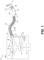
- the respiratory system 10 can include a main device housing 100.
- the main device housing 100 can contain a flow generator 11 that can be in the form of a motor/impeller arrangement, an optional humidifier or humidification chamber 12, a controller 13, and a user interface 14.
- the user interface 14 can include a display and input device(s) such as button(s), a touch screen, a combination of a touch screen and button(s), or the like.
- the controller 13 can include one or more hardware and/or software processors and can be configured or programmed to control the components of the system, including but not limited to operating the flow generator 11 to create a flow of gases for delivery to a patient, operating the humidifier or humidification chamber 12 (if present) to humidify and/or heat the gases flow, receiving user input from the user interface 14 for reconfiguration and/or user-defined operation of the respiratory system 10, and outputting information (for example on the display) to the user.
- the user can be a patient, healthcare professional, or others.
- the gases flow can be generated by the flow generator 11, and may be humidified, before being delivered to the patient via the patient breathing conduit 16 through the patient interface 17.
- the controller 13 can control the flow generator 11 to generate a gases flow of a desired flow rate, and/or one or more valves to control mixing of air and oxygen or other breathable gas.
- the controller 13 can control a heating element in the humidification chamber 12, if present, to heat the gases to a desired temperature that achieves a desired level of temperature and/or humidity for delivery to the patient.
- the patient breathing conduit 16 can have a heating element 16a, such as a heater wire, to heat gases flow passing through to the patient.
- the heating element 16a can also be under the control of the controller 13.
- the system 10 can use ultrasonic transducer(s), flow sensor(s) such as a thermistor flow sensor, pressure sensor(s), temperature sensor(s), humidity sensor(s), or other sensors, in communication with the controller 13, to monitor characteristics of the gases flow and/or operate the system 10 in a manner that provides suitable therapy.
- the gases flow characteristics can include gases concentration, flow rate, pressure, temperature, humidity, or others.
- the sensors 3a, 3b, 3c, 20, 25, such as pressure, temperature, humidity, and/or flow sensors, can be placed in various locations in the main device housing 100, the patient conduit 16, and/or the patient interface 17.
- Typical flow rates for pediatric users often range from, but are not limited to, about one liter per minute per kilogram of user weight to about three liters per minute per kilogram of user weight or greater.
- High flow therapy can also optionally include gas mixture compositions including supplemental oxygen and/or administration of therapeutic medicaments.
- High flow therapy is often referred to as nasal high flow (NHF), humidified high flow nasal cannula (HHFNC), high flow nasal oxygen (HFNO), high flow therapy (HFT), or tracheal high flow (THF), among other common names.
- High flow therapy can be effective in meeting or exceeding the patient's inspiratory demand, increasing oxygenation of the patient and/or reducing the work of breathing. Additionally, high flow therapy may generate a flushing effect in the nasopharynx such that the anatomical dead space of the upper airways is flushed by the high incoming gases flow. The flushing effect can create a reservoir of fresh gas available of each and every breath, while minimizing re-breathing of carbon dioxide, nitrogen, etc.
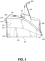
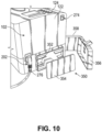
- the main housing upper chassis 102 can further include a substantially vertical right side outer wall 116 that is oriented in a front-to-rear direction of the main housing 100, a substantially vertical right side inner wall 118 that is oriented in a front-to-rear direction of the main housing 100, and an interconnecting wall 120 that extends between and interconnects the upper ends of the right side inner and outer walls 116, 118.
- the interconnecting walls 114, 120 are angled towards respective outer edges of the main housing 100, but can alternatively be substantially horizontal or inwardly angled.
- the main housing lower chassis 202 can be attachable to the upper chassis 102, either by suitable fasteners or integrated attachment features such as clips for example.
- the main housing lower chassis 202 can include a substantially vertical left side outer wall 210 that is oriented in a front-to-rear direction of the main housing 100 and is contiguous with the left side outer wall 110 of the upper chassis 102, and a substantially vertical right side outer wall 216 that is oriented in a front-to-rear direction of the main housing 100 and is contiguous with the right side outer wall 116 of the upper chassis 102.
- the main housing lower chassis 202 can further include a substantially vertical rear outer wall 222 that is contiguous with the rear outer wall 122 of the upper chassis 102.
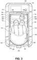
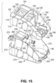
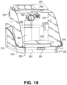
- the lower chassis 202 can have a motor recess 250 for receipt of a motor and sensor module.
- the motor and sensor module may be non-removable from the main housing 100.
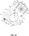
- the motor and sensor module can be removable from the main housing 100, as illustrated in Figures 17-18 .
- a recess opening 251 can be provided in the bottom wall 230 adjacent a rear edge thereof, for receipt of a motor/sensor module.
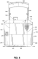
- a continuous, gas impermeable, unbroken peripheral wall 252 can be integrally formed with the bottom wall 230 of the lower chassis 202 and extend upwardly from the periphery of the opening 251.
- the motor and sensor module can be insertable into the recess 250 and attachable to the lower chassis 202. Upon insertion of the motor and sensor module into the lower chassis 202, the gases flow passage tube 264 can extend through the downward extension tube 133 and be sealed by the soft seal.
- the humidification chamber 300 can be fluidly coupled to the apparatus 10 in a linear slide-on motion in a rearward direction of the humidification chamber 300 into the chamber bay 108, from a position at the front of the housing 100 in a direction toward the rear of the housing 100.
- a gases outlet port 322 can be in fluid communication with the motor.
- a gases inlet port 340 (humidified gases return) as shown in Figure 8 can include a removable L-shaped elbow.
- the removable elbow can further include a patient outlet port 344 for coupling to the patient conduit 16 to deliver gases to the patient interface.
- the gases outlet port 322, gases inlet port 340, and patient outlet port 344 each can have soft seals such as O-ring seals or T-seals to provide a sealed gases passageway between the apparatus 10, the humidification chamber 300, and the patient conduit 16.
- the humidification chamber gases inlet port 306 can be complementary with the gases outlet port 322, and the humidification chamber gases outlet port 308 can be complementary with the gases inlet port 340.
- the axes of those ports can be parallel to each other to enable the humidification chamber 300 to be inserted into the chamber bay 108 in a linear movement.
- the respiratory device can have air and oxygen (or alternative auxiliary gas) inlets in fluid communication with the motor to enable the motor to deliver air, oxygen (or alternative auxiliary gas), or a mixture thereof to the humidification chamber 300 and thereby to the patient.
- the device can have a combined air/oxygen (or alternative auxiliary gas) inlet arrangement 350.
- This arrangement can include a combined air/oxygen port 352 into the housing 100, a filter 354, and a cover 356 with a hinge 358.
- a gases tube can also optionally extend laterally or in another appropriate direction and be in fluid communication with an oxygen (or alternative auxiliary gas) source.
- the port 352 can be fluidly coupled with the motor 402.
- the port 352 may be coupled with the motor/sensor module 400 via a gases flow passage between the port 352 and an inlet aperture or port in the motor and sensor module 400, which in turn would lead to the motor.
- the device can have the arrangement shown in Figures 11 to 14 to enable the motor to deliver air, oxygen (or alternative auxiliary gas), or a suitable mixture thereof to the humidification chamber 300 and thereby to the patient.
- This arrangement can include an air inlet 356' in the rear wall 222 of the lower chassis 202 of the housing 100.
- the air inlet 356' comprises a rigid plate with a suitable grill arrangement of apertures and/or slots. Sound dampening foam may be provided adjacent the plate on the interior side of the plate.
- An air filter box 354' can be positioned adjacent the air inlet 356' internally in the main housing 100, and include an air outlet port 360 to deliver filtered air to the motor via an air inlet port 404 in the motor/sensor module 400.
- the air filter box 354' may include a filter configured to remove particulates (e.g. dust) and/or pathogens (e.g. viruses or bacteria) from the gases flow.
- a soft seal such as an O-ring seal can be provided between the air outlet port 360 and air inlet port 404 to seal between the components.
- the device can include a separate oxygen inlet port 358' positioned adjacent one side of the housing 100 at a rear end thereof, the oxygen port 358' for receipt of oxygen from an oxygen source such as a tank or source of piped oxygen.
- the oxygen inlet port 358' is in fluid communication with a valve 362.
- the valve 362 can suitably be a solenoid valve that enables the control of the amount of oxygen that is added to the gases flow that is delivered to the humidification chamber 300.
- the oxygen port 358' and valve 362 may be used with other auxiliary gases to control the addition of other auxiliary gases to the gases flow.
- the other auxiliary gases can include any one or more of a number of gases useful for gas therapy, including but not limited to heliox and nitric oxide.
- the lower housing chassis 202 can include suitable electronics boards, such as sensing circuit boards.
- the electronics boards can be positioned adjacent respective outer side walls 210, 216 of the lower housing chassis 202.
- the electronics boards can contain, or can be in electrical communication with, suitable electrical or electronics components, such as but not limited to microprocessors, capacitors, resistors, diodes, operational amplifiers, comparators, and switches. Sensors can be used with the electronic boards.
- Components of the electronics boards (such as but not limited to one or more microprocessors) can act as the controller 13 of the apparatus.
- One or both of the electronics boards can be in electrical communication with the electrical components of the apparatus 10, including the display unit and user interface 14, motor, valve 362, and the heater plate 140 to operate the motor to provide the desired flow rate of gases, operate the humidification chamber 300 to humidify and heat the gases flow to an appropriate level, and supply appropriate quantities of oxygen (or quantities of an alternative auxiliary gas) to the gases flow.
- the electronics boards can be in electrical communication with a connector arrangement 274 projecting from the rear wall 122 of the upper housing chassis 102.
- the connector arrangement 274 may be coupled to an alarm, pulse oximetry port, and/or other suitable accessories.
- the electronics boards can also be in electrical communication with an electrical connector 276 that can also be provided in the rear wall 122 of the upper housing chassis 102 to provide mains or battery power to the components of the device.
- operation sensors such as flow, temperature, humidity, and/or pressure sensors can be placed in various locations in the respiratory device, the patient breathing conduit 16, and/or cannula 17 such as shown in Figure 1 .
- the electronics boards can be in electrical communication with those sensors. Output from the sensors can be received by the controller 13, to assist the controller 13 to operate the respiratory system 10 in a manner that provides optimal therapy, including meeting inspiratory demand.
- the electronics boards and other electrical and electronic components can be pneumatically isolated from the gases flow path to improve safety.
- the sealing also prevents water ingress.
- FIG. 19A illustrates a block diagram 900 of an example control system 920 (which can be the controller 13 in Figure 1 ) that can detect patient conditions and control operation of the respiratory system including the gases source.
- the control system 920 can manage a flow rate of the gases flowing through the respiratory system as the gases are delivered to a patient.
- the control system 920 can increase or decrease the flow rate by controlling an output of a motor speed of the blower (hereinafter also referred to as a "blower motor") 930 or an output of a valve 932 in a blender.
- the control system 920 can automatically determine a set value or a personalized value of the flow rate for a particular patient as discussed below.
- the flow rate can be optimized by the control system 920 to improve patient comfort and therapy.
- the control system 920 can also generate audio and/or display/visual outputs 938, 939.
- the flow therapy apparatus can include a display and/or a speaker.
- the display can indicate to the physicians any warnings or alarms generated by the control system 920.
- the display can also indicate control parameters that can be adjusted by the physicians.
- the control system 920 can automatically recommend a flow rate for a particular patient.
- the control system 920 can also determine a respiratory state of the patient, including but not limited to generating a respiratory rate of the patient, and send it to the display, which will be described in greater detail below.
- the control system 920 can change heater control outputs to control one or more of the heating elements (for example, to maintain a temperature set point of the gases delivered to the patient).
- the control system 920 can also change the operation or duty cycle of the heating elements.
- the heater control outputs can include heater plate control output(s) 934 and heated breathing tube control output(s) 936.
- the control system 920 can determine the outputs 930-939 based on one or more received inputs 901-916.
- the inputs 901-916 can correspond to sensor measurements received automatically by the controller 600 (shown in FIG. 19B ).
- the control system 920 can receive sensor inputs including but not limited to temperature sensor(s) inputs 901, flow rate sensor(s) inputs 902, motor speed inputs 903, pressure sensor(s) inputs 904, gas(s) fraction sensor(s) inputs 905, humidity sensor(s) inputs 906, pulse oximeter (for example, SpO 2 ) sensor(s) inputs 907, stored or user parameter(s) 908, duty cycle or pulse width modulation (PWM) inputs 909, voltage(s) inputs 910, current(s) inputs 911, acoustic sensor(s) inputs 912, power(s) inputs 913, resistance(s) inputs 914, CO 2 sensor(s) inputs 915, and/or spirometer inputs 916.
- PWM
- the control system 920 can receive inputs from the user or stored parameter values in a memory 624 (shown in FIG. 19B ).
- the control system 920 can dynamically adjust flow rate for a patient over the time of their therapy.
- the control system 920 can continuously detect system parameters and patient parameters.
- a person of ordinary skill in the art will appreciate based on the disclosure herein that any other suitable inputs and/or outputs can be used with the control system 920.
- the controller 600 can also include circuits 628 for receiving sensor signals.
- the controller 600 can further include a display 630 for transmitting status of the patient and the respiratory assistance system.
- the display 630 can also show warnings and/or other alerts.
- the display 630 can be configured to display characteristics of sensed gas(es) in real time or otherwise.
- the controller 600 can also receive user inputs via the user interface such as display 630.
- the user interface can include button(s) and/or dial(s).
- the user interface can comprise a touch screen.
- any of the features of the respiratory system described herein including but not limited to the humidification chamber, the flow generator, the user interface, the controller, and the patient breathing conduit configured to couple the gases flow outlet of the respiratory system to the patient interface, can be combined with any of the sensor modules described herein.
- FIG 20 illustrates a block diagram of the motor and sensor module 2000, which can be received by the recess 250 in the respiratory device (shown in Figures 17 and 18 ).
- the motor and sensor module can include a blower 2001, which entrains room air to deliver to a patient.
- the blower 2001 can be a centrifugal blower.
- One or more sensors may be used to measure a motor speed of the blower motor.
- the blower motor may comprise a brushless DC motor, from which motor speed can be measured without the use of separate sensors. For example, during operation of a brushless DC motor, back-EMF can be measured from the non-energized windings of the motor, from which a motor position can be determined, which can in turn be used to calculate a motor speed.
- a motor driver may be used to measure motor current, which can be used with the measured motor speed to calculate a motor torque.
- the blower motor may comprise a low inertia motor.
- Room air can enter a room air inlet 2002, which enters the blower 2001 through an inlet port 2003.
- the inlet port 2003 can include a valve 2004 through which a pressurized gas may enter the blower 2001.
- the valve 2004 can control a flow of oxygen into the blower 2001.
- the valve 2004 can be any type of valve, including a proportional valve or a binary valve. In some embodiments, the inlet port does not include a valve.
- the blower 2001 can operate at a motor speed of greater than 1,000 RPM and less than 30,000 RPM, greater than 2,000 RPM and less than 21,000 RPM, or between any of the foregoing values. Operation of the blower 2001 mixes the gases entering the blower 2001 through the inlet port 2003. Using the blower 2001 as the mixer can decrease the pressure drop that would otherwise occur in a system with a separate mixer, such as a static mixer comprising baffles, because mixing requires energy.
- the mixed air can exit the blower 2001 through a conduit 2005 and enters the flow path 2006 in the sensor chamber 2007.
- a sensing circuit board with sensors 2008 can positioned in the sensor chamber 2007 such that the sensing circuit board is at least partially immersed in the gases flow. At least some of the sensors 2008 on the sensing circuit board can be positioned within the gases flow to measure gases properties within the flow. After passing through the flow path 2006 in the sensor chamber 2007, the gases can exit 2009 to the humidification chamber.
- Positioning sensors 2008 downstream of the combined blower and mixer 2001 can increase accuracy of measurements, such as the measurement of gases fraction concentration, including oxygen concentration, over systems that position the sensors upstream of the blower and/or the mixer. Such a positioning can give a repeatable flow profile. Further, positioning the sensors downstream of the combined blower and mixer avoids the pressure drop that would otherwise occur, as where sensing occurs prior to the blower, a separate mixer, such as a static mixer with baffles, is required between the inlet and the sensing system. The mixer can introduce a pressure drop across the mixer. Positioning the sensing after the blower can allow the blower to be a mixer, and while a static mixer would lower pressure, in contrast, a blower increases pressure.
- immersing at least part of the sensing circuit board and sensors 2008 in the flow path can increase the accuracy of measurements because the sensors being immersed in the flow means they are more likely to be subject to the same conditions, such as temperature and pressure, as the gases flow and therefore provide a better representation of the gases flow characteristics.
- the gases exiting the blower can enter a flow path 402 in a sensor chamber 400, which can be positioned within the motor and sensor module and can be the sensor chamber 2007 of Figure 20 .
- the flow path 402 can have a curved shape.
- the flow path 402 can be configured to have a curved shape with no sharp turns.
- the flow path 402 can have curved ends with a straighter section between the curved ends.
- a curved flow path shape can reduce pressure drop in a gases flow without reducing the sensitivity of flow measurements by partially coinciding a measuring region with the flow path to form a measurement portion of the flow path, which will be described below with reference to Figures 23A-23B .
- a sensing circuit board 404 with sensors can be positioned in the sensor chamber 400 such that the sensing circuit board 404 is at least partially immersed in the flow path 402. Immersing at least part of the sensing circuit board and sensors in the flow path can increase the accuracy of measurements because the sensors immersed in the flow are more likely to be subject to the same conditions, such as temperature and pressure, as the gases flow, and therefore provide a better representation of the characteristics of the gases flow.
- the gases After passing through the flow path 402 in the sensor chamber 400, the gases can exit to the humidification chamber.
- the gases flow rate may be measured using at least two different types of sensors.
- the first type of sensor can comprise a thermistor, which can determine a flow rate by monitoring heat transfer between the gases flow and the thermistor.
- the thermistor flow sensor can run the thermistor at a constant target temperature within the flow when the gases flow around and past the thermistor.
- the sensor can measure an amount of power required to maintain the thermistor at the target temperature.
- the target temperature can be configured to be higher than a temperature of the gases flow, such that more power is required to maintain the thermistor at the target temperature at a higher flow rate.
- the thermistor flow rate sensor can also maintain a plurality of (for example, two, three, or more) constant temperatures on a thermistor to avoid the difference between the target temperature and the gases flow temperature from being too small or too large.
- the plurality of different target temperatures can allow the thermistor flow rate sensor to be accurate across a large temperature range of the gases.
- the thermistor circuit can be configured to be able to switch between two different target temperatures, such that the temperature of the gases flow will always fall within a certain range relative to one of the two target temperatures (for example, not too close but not too far).
- the thermistor circuit can be configured to operate at a first target temperature of about 50°C to about 70°C, or about 66°C.
- the first target temperature can be associated with a desirable flow temperature range of between about 0 0 C to about 60°C, or about 0°C and about 40°C.
- the thermistor circuit can be configured to operate at a second target temperature of about 90°C to about 110°C, or about 100°C.
- the second target temperature can be associated with a desirable flow temperature range of between about 20°C to about 100°C, or about 30°C and about 70°C.
- the controller can be configured to adjust the thermistor circuit to change between at least the first and second target temperature modes by connecting or bypassing a resistor within the thermistor circuit.
- the thermistor circuit can be arranged as a Wheatstone bridge configuration comprising a first voltage divider arm and a second voltage divider arm. The thermistor can be located on one of the voltage divider arms. More details of a thermistor flow rate sensor are described in PCT Application No. PCT/NZ2017/050119, filed September 3, 2017 .
- the second type of sensor can comprise an acoustic sensor assembly.
- Acoustic sensors including acoustic transmitters and/or receivers can be used to measure a time of flight of acoustic signals to determine gases velocity and/or composition, which can be used in flow therapy apparatuses.
- a driver causes a first sensor, such as an ultrasonic transducer, to produce an ultrasonic pulse in a first direction.
- a second sensor such as a second ultrasonic transducer, receives this pulse and provides a measurement of the time of flight of the pulse between the first and second ultrasonic transducers.
- the speed of sound of the gases flow between the ultrasonic transducers can be calculated by a processor or controller of the respiratory system.
- the second sensor can transmit and the first sensor can receive a pulse in a second direction opposite the first direction to provide a second measurement of the time of flight, allowing characteristics of the gases flow, such as a flow rate or velocity, to be determined.
- acoustic pulses transmitted by an acoustic transmitter, such as an ultrasonic transducer can be received by acoustic receivers, such as microphones. More details of an acoustic flow rate sensor are described in PCT application PCT/NZ2016/050193, filed December 2, 2016 .
- Readings from both the first and second types of sensors can be combined to determine a more accurate flow measurement. For example, a previously determined flow rate and one or more outputs from one of the types of sensor can be used to determine a predicted current flow rate. The predicted current flow rate can then be updated using one or more outputs from the other one of the first and second types of sensor, in order to calculate a final flow rate.
- a breathing signal is detected in the flow rate or other flow parameters due to the flow resistance variation caused by inhalation and exhalation.
- the patient can be detached from the breathing system such that there is no breathing signal in the gases flow parameter.
- the controller can compare the first value with a first threshold. If the first value is above the first threshold, the controller can deem the flow parameter data to be unsuitable, and the flow data point can be discarded at step 2344. If the first value is below the first threshold, the controller can deem the flow parameter data to be suitable at step 2345.
- oxygen (or other supplementary gas) concentration data can be used.
- Oxygen concentration data can be determined using one or more sensors in the respiratory device, such as ultrasonic sensors.
- Oxygen flow rate from the oxygen source can be determined by an oxygen flow rate sensor located downstream of the oxygen source.
- the controller can take a comparatively longer time (than when the patient is attached and breathing via the patient interface) to determine that a patient is detached, but can take a comparatively shorter time to determine that a patient is attached.
- This is in part because a number of algorithms for controlling the flow rate and/or motor speed of the respiratory device rely on a patient being attached in order to function. Incorrectly determining that a patient is detached may prevent these algorithms from functioning when needed. This may prevent the device from synchronizing the delivery of gases with the patient's breathing and/or reduce the effect of the respiratory therapy. Further, incorrectly determining that a patient is detached may result in discomfort due to incorrect flow rate and/or motor speed to the patient who is still attached to the patient interface.
- the estimated effect can assume no noise or patient interaction.
- the estimated effect can be calculated using the current value of the second parameter, such as the current motor speed, as well as a running average of a relationship between the motor speed and flow rate, which can be used to characterize the relationship between the first flow parameter and the second flow parameter.
- the flow parameter variation data can be determined by subtracting a first average value of the flow parameter data from a second average value of the flow parameter data.
- the first average value can be later in time than the second average value.
- the first average value can also be based on a longer window of data than the second average value.
- the second average value can be based on a longer window of data than the first average value.
- the windows of data can be mutually exclusive in time or overlapping in time.
- selecting a portion of the processed flow parameter data relating to a longer period of time can result in filtering out breathing signals with higher frequencies compared to selecting a portion of the processed flow parameter data relating to a shorter period of time. Accordingly, there can be a tradeoff between filtering noise and detecting or capturing instantaneous changes when selecting a portion of the processed flow parameter data representing a length of time. In a configuration, it can be advantageous to select a portion of the processed flow parameter data representing a length of time that is less than a breathing period.
- selecting a portion of the processed flow parameter data representing in the range of 0.5-2 seconds can provide reliability in detecting patient interaction or attachment for the majority of expected breathing frequencies (as well as talking, coughing, etc.), while being a length that makes it less likely to generate a false determination of patient attachment or interaction due to random noise.
- the selected portion of the processed flow parameter data can be less than 0.5, 0.5-1, 1-1.5, 1.5-2, 2-2.5, 2.5-3, 3-3.5, 3.5-4, 4-4.5, 4.5-5, 5-5.5, 5.5-6, or more than 6 seconds.
- the controller selects a portion of the processed flow parameter data before generating the flow parameter variation data at step 2608.
- the controller selects a portion (or window) of the processed flow parameter data relating to a specific length of time such that the signal noise is filtered out of the measure of instantaneous patient ventilation, described hereafter.
- the controller selects a portion of the processed flow parameter data relating to a specific length of time such that expected breathing frequencies, which can include all expected breathing frequencies, result in an increased measure of instantaneous patient ventilation.
- the controller fits one or more functions to the selected portion of the flow parameter variation data.
- the one or more functions can be algebraic, such as polynomial (for example, constant, linear, non-linear, quadratic, cubic, etc.), rational, root, and/or others.
- the one or more functions can be transcendental, such as exponential, hyperbolic, logarithmic, power, periodic (for example, trigonometric, etc.), and/or others.
- the controller can perform a variety of line and/or curve fitting techniques to fit the one or more functions to the selected portion of the flow parameter variation data, which can include the non-limiting example techniques of regression analysis, interpolation, extrapolation, linear least squares, non-linear least squares, total least squares, simple linear regressions, robust simple linear regression, polynomial regression, orthogonal regression, Deming regression, linear segmented regression, regression dilution, and/or others.
- the one or more functions which includes at least those above, can generate a curve.
- the curve can be a line.
- the lines or curves described herein can include a plurality of curves, vertices, and/or other features.
- the lines described herein can be straight, angled, and/or horizontal.
- the lines described herein can be a line of best fit.
- the controller can perform a least squares fit of a line, which can include fitting a linear function such as a straight line, to the selected portion of flow parameter variation data.
- t can be a linearly increasing normalized time parameter that is equal to minus one at the oldest data point used and equal to one at the most recent data points used.
- the controller can fit a horizontal line to the selected portion of flow parameter variation data.
- the horizontal line can be the average of the flow parameter variation data representing or relating to the selected portion.
- the controller generates a measure of patient ventilation.
- the measure of patient ventilation can mainly relate to patient ventilation but may include some noise.
- the controller can generate a measure of instantaneous patient ventilation, also referred to as a flow volume parameter or volume measurement, by determining an area under the function fit to the selected portion of the flow parameter variation data at step 2612.
- the controller can generate a measure of instantaneous patient ventilation by determining the area under a curve generated by the function fit to the flow parameter variation data at step 2612.
- the controller can generate a measure of instantaneous patient ventilation by determining the area under the absolute value of the one or more functions or curve generated by the one or more functions at step 2612. This can be determined by taking the integral of the absolute value of the one or more functions or curve generated by the one or more functions at step 2612. In one non-limiting example, this is represented in the equation illustrated below.
- the measure of instantaneous patient ventilation ( V 0 ) can be multiplied by one minute to be representative of minute patient ventilation.
- the measure of instantaneous patient ventilation can be filtered over time to generate the measure of patient ventilation which can be used to determine patient attachment.
- the measure of patient ventilation can be a measure of volume.
- the measure of patient ventilation can be represented by V ⁇ 0 .
- a filter coefficient can be set such that data relating to approximately one minute is used. A longer filter coefficient can be used to make the determination of patient attachment more reliable but that configuration may be slower to react to the attachments and detachments of a patient.
- the controller generates a measure of total signal fluctuation.
- the measure of total signal fluctuation can include noise resulting from electronics of the respiratory system, signal noise, the environment, patient respiration, patient ventilation, patient movement, and/or other noise originating from or not originating from the patient.
- the controller can generate a measure of instantaneous total signal fluctuation from the flow parameter variation data generated at step 2608.
- each data point for the offset can instead be made positive by taking the square of the flow parameter variation data. Taking the square of the flow parameter variation data, however, can result in erroneous patient attachment determinations due to random outliers in the flow parameter variation data. Utilizing the absolute value can be more tolerant to outlier values in the flow parameter variation data which can result from coughing, yawning, etc.
- the measure of instantaneous total signal fluctuation ( V short ) can be multiplied by one minute, similar to V 0 .
- the measure of instantaneous total signal fluctuation can be considered to be representative of the total fluctuations in the flow parameter variation data resulting from both the patient signal and random noise.
- the measure of instantaneous total signal fluctuation can be filtered over time to generate a measure of total signal fluctuation to facilitate determining patient attachment.
- the measure of total signal fluctuation can be represented by V ⁇ s hort .
- a filter coefficient can be set such that data relating to approximately one minute is used. A longer filter coefficient could be used to make the determination of patient attachment more reliable but that configuration could be slower to react to the attachments and detachments of a patient.
- the measure of patient ventilation ( V ⁇ 0 ) can be greater than or equal to the measure of total signal fluctuation ( V ⁇ short ), which can be greater than or equal to 0.
- the controller can determine patient attachment, at step 2618, by comparing the two values as shown in Figures 27 and 28 .
- the controller can determine four categories of the patient attachment status, that is, whether the patient is detached, attaching, attached, or detaching to or from the respiratory system, using the filtered features described above.
- This assessment can be made by comparing the main filtered feature with one or more feature thresholds (such as a threshold close to 1 or slightly below 1 as described above).
- the main filtered feature In order to arrive at a determination that the patient is attached or detached, the main filtered feature must be above or below a threshold.
- the threshold can be determined by further analyzing the recent variation in the main filtered feature, the previously calculated sum of recent changes in the flow conductance, and/or the value of the feature if the signal includes pure noise, that is, the known value of the feature when no patient is attached.
- the controller can determine whether the patient is previously attached to or in the process of detaching (that is, still attached to) the respiratory system. If the patient is not previously attached or detaching, that is, if the patient is detached or attaching, at step 2542, the controller can determine whether the main filtered feature is greater than a first threshold, or has the patient been attaching for a predetermined amount of time. If the main filtered feature is greater than the first threshold, or if the patient has been attaching to the respiratory system for at least the predetermined amount of time, at step 2550, the controller can determine that the patient is attached to the respiratory system.
- the controller can determine whether the main filtered feature is greater than a second threshold that is lower than the first threshold. If the main filtered feature is less than the second threshold, at step 2546, the controller can determine that the patient is detached. If the main filtered feature is greater than the second threshold, but is not greater than the first threshold (that is, between the first and second thresholds), at step 2548, the controller can determine that the patient is attaching to the respiratory system.
- the controller can determine whether the main filtered feature is less than a third threshold, or has the patient been in the process of detaching for a predetermined amount of time. If the main filtered feature is lower than the third threshold, or if the patient has been detaching for a predetermined amount of time, at step 2534, the controller can determine that the patient is detached.
- the controller can determine whether the main filtered feature is lower than a fourth threshold that is higher than the third threshold. If the main filtered feature is lower than the fourth threshold but not lower than the third threshold (that is, between the third and fourth threshold), at step 2538, the controller can determine the patient is detaching from the respiratory system. If the main filtered feature is not lower (or higher) than the fourth threshold, at step 2540, the controller can determine that the patient is attached.
- the first and fourth thresholds can be the same or different (for example, the fourth threshold can be lower than the first threshold).
- the second and fourth thresholds can be the same or different (for example, the fourth threshold can be lower than the second threshold).
- the absolute value of the difference between the first and second thresholds and the difference between the third and fourth thresholds can be the same or different.
- the process illustrated in Figure 25B ensures that the controller does not make a determination that the patient is attached or detached based on the main filtered feature briefly crossing a threshold by a small amount, for example, by determining that the patient is still in the process of attaching to or detaching from the respiratory system. If the main filtered feature crosses the threshold, but not by a significant amount, the patient is determined to be attaching or detaching. Further, if the patient is determined to be attaching or detaching for a certain amount of time, the determination can switch to attached or detached, without needing the main filtered feature to be significantly above or below the feature threshold.
- the controller can determine the patient attachment status, for example whether the patient is attached to or detached from the respiratory system, using the generated measure of patient ventilation ( V ⁇ 0 ) and measure of total signal fluctuation ( V ⁇ short ) described above in reference to Figure 26 . This determination can be made by comparing the measure of patient ventilation ( V ⁇ 0 ) and measure of total signal fluctuation ( V ⁇ short ). If the measure of patient ventilation ( V ⁇ 0 ) and measure of total signal fluctuation ( V ⁇ short ) are similar, the controller can determine that the majority of the signal variation is caused by the patient, and consequently, the patient is attached or connected.
- the controller can determine that the majority of signal variation is caused by random noise, and therefore, a patient is not attached or connected.
- the controller can determine that the majority of the signal variation is caused by the patient, and consequently, the patient is attached or connected.
- the controller can determine that the majority of signal variation is caused by random noise, and therefore, a patient is not attached or connected.
- the relationship between the measure of patient ventilation ( V ⁇ 0 ) and measure of total signal fluctuation ( V ⁇ s hort ) can be represented by a patient connection measure ( ⁇ ), which can be determined by (or including in part) the ratio between V ⁇ 0 and V ⁇ short .
- a patient connection measure ⁇
- the equation below can be used to calculate the patient connection measure ( ⁇ ).
- the patient connection measure ( ⁇ ) can be determined in part by using a correction factor.
- the correction factor can be determined by comparing two or more measures of instantaneous patient ventilation ( V 0 ) with each being calculated by a different method.
- the correction factor can be determined by comparing two or more measures of patient ventilation ( V ⁇ 0 ) with each being calculated by a different method.
- the correction factor can be used as an indication of the smoothness of the respiratory flow of the patient.
- the patient connection measure ( ⁇ ) can be related to the signal noise ratio (SNR). In one non-limiting example, the relationship can be represented by the equation below. ⁇ ⁇ SNR 2 1 + SNR 2
- the patient connection measure ( ⁇ ) can be zero when the signal noise ratio (SNR) is zero.
- the patient connection measure ( ⁇ ) can approach zero as the signal noise ratio (SNR) approaches zero.
- the patient connection measure ( ⁇ ) can be one when the signal noise ratio (SNR) is infinite.
- the patient connection measure ( ⁇ ) can approach one as the signal noise ratio (SNR) approaches infinity.
- the patient connection measure ( ⁇ ) can be used to determine patient attachment by comparing the patient connection measure ( ⁇ ) with one or more thresholds.
- the controller can also alternatively determine whether the patient is attached to the respiratory system by comparing any one of the patient connection measure, the correction factor, any measures of patient minute ventilation, or any combinations thereof, against specific thresholds. The combinations can be based on an average value or any weighted average value.
- the correction factor and/or the measures of minute ventilation tend towards 0 when a patient is detached, and as such should exceed a certain threshold if a patient is attached to the respiratory system.
- the controller can, at decision step 2702, determine whether the patient is previously attached to or detached from the respiratory system. If the patient is previously detached, at step 2704, the controller can determine whether the patient connection measure ( ⁇ ), which can be, for example, the ratio between the measure of patient ventilation ( V ⁇ 0 ) and measure of total signal fluctuation ( V ⁇ short ), exceeds an attachment threshold. If the patient connection measure ( ⁇ ) exceeds the attachment threshold, the controller determines at step 2706 that the patient is attached. If the patient connection measure ( ⁇ ) does not exceed the attachment threshold, the controller determines at step 2708 that the patient is detached.
- the attachment threshold can be set to a value that corresponds to a signal to noise ratio above which it can be reliably assumed that the fluctuations are not entirely generated by random noise.
- the controller can determine whether the patient connection measure ( ⁇ ) falls below a detachment threshold. If the patient connection measure ( ⁇ ) falls below the detachment threshold, the controller determines at step 2714 that the patient is detached. If the patient connection measure ( ⁇ ) does not fall below the detachment threshold, the controller determines at step 2712 that the patient is attached.
- the detachment threshold is below the attachment threshold.
- the detachment threshold can be set at a value at which the variations can be reliably assumed to be solely caused by random noise. In a configuration, at step 2710, the controller can determine whether the patient connection measure ( ⁇ ) falls below the detachment threshold continuously for a set time period.
- the time period can be such that a short time period of data, such as a few seconds, will have been decayed away by the end of the time period. This can advantageously prevent a few seconds of erroneous data from resulting in an incorrect determination of patient attachment.
- the controller can determine four categories of the patient attachment status, that is, whether the patient is detached, attaching to, attached, or detaching from the respiratory system, using the patient connection measure ( ⁇ ) described above. This assessment can be made by comparing the patient connection measure ( ⁇ ), also described as a ratio, with one or more thresholds. In order to arrive at a determination that the patient is attached or detached, the patient connection measure ( ⁇ ) must be above or below a threshold.
- the controller can determine whether the patient is previously attached to or in the process of detaching (that is, still attached to) the respiratory system. If the patient is not previously attached or detaching, that is, if the patient is detached or attaching, at step 2842, the controller can determine whether patient connection measure ( ⁇ ) is greater than a first threshold, or has the patient been attaching for a predetermined amount of time. If the patient connection measure ( ⁇ ) is greater than the first threshold, or if the patient has been attaching to the respiratory system for at least the predetermined amount of time, at step 2850, the controller can determine that the patient is attached to the respiratory system.
- the controller can determine whether the patient connection measure ( ⁇ ) is greater than a second threshold that is lower than the first threshold. If the patient connection measure ( ⁇ ) is less than the second threshold, at step 2846, the controller can determine that the patient is detached. If the patient connection measure ( ⁇ ) is greater than the second threshold, but is not greater than the first threshold (that is, between the first and second thresholds), at step 2848, the controller can determine that the patient is attaching to the respiratory system.
- the controller can determine whether the patient connection measure ( ⁇ ) is less than a third threshold, or has the patient been in the process of detaching for a predetermined amount of time. If the patient connection measure ( ⁇ ) is lower than the third threshold, or if the patient has been detaching for a predetermined amount of time, at step 2834, the controller can determine that the patient is detached.
- the controller can determine whether the patient connection measure ( ⁇ ) is lower than a fourth threshold that is higher than the third threshold. If the patient connection measure ( ⁇ ) is lower than the fourth threshold but not lower than the third threshold (that is, between the third and fourth threshold), at step 2838, the controller can determine the patient is detaching from the respiratory system. If the patient connection measure ( ⁇ ) is not lower (or higher) than the fourth threshold, at step 2840, the controller can determine that the patient is attached.
- the controller can generate a proxy measure of patient ventilation ( V ) based on the measure of patient ventilation ( V ⁇ 0 ).
- the controller can generate the proxy measure of patient ventilation ( V ) based on the patient connection measure ( ⁇ ) and measure of total signal fluctuation ( V ⁇ short ), as represented in the function below.
- the patient's minute ventilation can be estimated using the absolute value of variations in the processed flow by taking into account the estimated proportion of these variations that was caused by the patient themselves.
- V f ⁇ V ⁇ short
- the respiratory device can generate an alarm when the patient becomes detached.
- the alarm can be generated instantly or after a preset time of determining that the patient has become detached.
- the preset time can be between about 10 seconds and about 10 minutes, or between about 30 seconds and 5 minutes, or between about 1 minute and about 2 minutes.
- the alarm can additionally be outputted to a nurse call port.
- the device can provide an option for the user, for example, via the user interface of the respiratory device, to confirm whether the patient has been detached from the device. If the patient is still attached to the device, the user can use the option to manually override the controller's determination that the patient has been detached.
- the override option can reduce false positive detections, for example, in cases where the patient may be attached to the device but breathing shallowly.
- Breath synchronization can include adjusting a flow source (such as the flow generator) to have a phase matching that of the patient's breath cycle, such as by increasing a flow rate when the patient is inhaling and/or decreasing a flow rate when the patient is exhaling.
- a patient breath cycle may be determined using one or more measured parameters, such as a flow rate, a blower motor speed, and/or a system pressure. Additional details of breath synchronization can be found in International Patent Publication No. WO 2017/200394, filed May 17, 2017 .
- the controller of the respiratory device can begin to increase the oxygen concentration in the mixture of gases to be delivered to the patient.
- the device can automatically adjust the FdO2 in order to achieve a targeted SpO2 value for the patient.
- the oxygen concentration in the gases flow can be high, which can result in a spike in the patient's oxygen saturation and be harmful to the patient.
- the patient detachment detection can be factored into the oxygen delivery control of the device so that the controller does not begin increasing the oxygen delivery or the controller switches to a specific value when the patient is determined to be detached from the device.
- the device can also be configured to close the valve to stop delivery of oxygen or other breathable gas to be mixed with air upon determining that the patient is detached. Closing the valve to the inlet of oxygen or other breathable gas can reduce the cost of providing the therapy and/or improve user safety.
- the device can be configured to reduce the flow rate, reduce or turn off power to the heating element of the humidification chamber, and/or reduce or turn off power to the heating element of the patient breathing conduit, upon determining that the patient is detached.
- the reduction in flow rate can reduce noise.
- the reduction in flow rate and/or the reduction of or turning off power to the heating element(s) of the humidification chamber and/or the patient breathing conduit can reduce power consumption of the device, thereby prolonging the battery life and/or the life of another power source of the device.
- the device can be configured to increase the flow rate for an initial period of time when the patient is determined to be detached. An increased flow rate can improve the reliability of the patient detection processes.
- the initial period of time of flow rate increase can be used to confirm that the patient has actually been detached from the device, that is, to reduce false positives. If the controller determines that the patient is detached at the higher flow rate, the device can take other actions as described above (for example, deactivating certain control algorithms, outputting an alarm, reducing the flow rate, reducing or turning off power to the heating elements of the humidification chamber and/or the patient breathing conduit, and/or the like).
- the initial period of time can be, for example, between about 10 seconds and about 10 minutes, or between about 30 seconds and 5 minutes, or between about 1 minute and about 2 minutes.
- the device can resume normal operation, for example, increasing the flow rate and/or turning on power to the heating elements of the humidification chamber and/or the patient breathing conduit, etc., upon detecting that the patient is re-attached to the device.
- each embodiment of this invention may comprise, additional to its essential features described herein, one or more features as described herein from each other embodiment of the invention disclosed herein.
Landscapes
- Health & Medical Sciences (AREA)
- Engineering & Computer Science (AREA)
- Public Health (AREA)
- General Health & Medical Sciences (AREA)
- Biomedical Technology (AREA)
- Life Sciences & Earth Sciences (AREA)
- Veterinary Medicine (AREA)
- Heart & Thoracic Surgery (AREA)
- Animal Behavior & Ethology (AREA)
- Anesthesiology (AREA)
- Pulmonology (AREA)
- Emergency Medicine (AREA)
- Hematology (AREA)
- Medical Informatics (AREA)
- Primary Health Care (AREA)
- Epidemiology (AREA)
- Surgery (AREA)
- Pathology (AREA)
- Biophysics (AREA)
- Molecular Biology (AREA)
- Business, Economics & Management (AREA)
- General Business, Economics & Management (AREA)
- Physics & Mathematics (AREA)
- Nuclear Medicine, Radiotherapy & Molecular Imaging (AREA)
- Urology & Nephrology (AREA)
- Measurement Of The Respiration, Hearing Ability, Form, And Blood Characteristics Of Living Organisms (AREA)
- Measuring And Recording Apparatus For Diagnosis (AREA)
Priority Applications (1)
| Application Number | Priority Date | Filing Date | Title |
|---|---|---|---|
| EP25182763.0A EP4593033A3 (en) | 2019-03-05 | 2020-03-04 | Patient attachment detection in respiratory flow therapy systems |
Applications Claiming Priority (3)
| Application Number | Priority Date | Filing Date | Title |
|---|---|---|---|
| US201962813981P | 2019-03-05 | 2019-03-05 | |
| US201962893122P | 2019-08-28 | 2019-08-28 | |
| PCT/IB2020/051816 WO2020178746A1 (en) | 2019-03-05 | 2020-03-04 | Patient attachment detection in respiratory flow therapy systems |
Related Child Applications (1)
| Application Number | Title | Priority Date | Filing Date |
|---|---|---|---|
| EP25182763.0A Division EP4593033A3 (en) | 2019-03-05 | 2020-03-04 | Patient attachment detection in respiratory flow therapy systems |
Publications (3)
| Publication Number | Publication Date |
|---|---|
| EP3934725A1 EP3934725A1 (en) | 2022-01-12 |
| EP3934725A4 EP3934725A4 (en) | 2022-12-21 |
| EP3934725B1 true EP3934725B1 (en) | 2025-06-25 |
Family
ID=72336917
Family Applications (2)
| Application Number | Title | Priority Date | Filing Date |
|---|---|---|---|
| EP20766870.8A Active EP3934725B1 (en) | 2019-03-05 | 2020-03-04 | Patient attachment detection in respiratory flow therapy systems |
| EP25182763.0A Pending EP4593033A3 (en) | 2019-03-05 | 2020-03-04 | Patient attachment detection in respiratory flow therapy systems |
Family Applications After (1)
| Application Number | Title | Priority Date | Filing Date |
|---|---|---|---|
| EP25182763.0A Pending EP4593033A3 (en) | 2019-03-05 | 2020-03-04 | Patient attachment detection in respiratory flow therapy systems |
Country Status (8)
| Country | Link |
|---|---|
| US (2) | US12161798B2 (enExample) |
| EP (2) | EP3934725B1 (enExample) |
| JP (2) | JP7763402B2 (enExample) |
| CN (3) | CN113556941A (enExample) |
| AU (2) | AU2020231108B2 (enExample) |
| SG (1) | SG11202109474PA (enExample) |
| TW (2) | TWI849071B (enExample) |
| WO (1) | WO2020178746A1 (enExample) |
Families Citing this family (8)
| Publication number | Priority date | Publication date | Assignee | Title |
|---|---|---|---|---|
| EP3934725B1 (en) | 2019-03-05 | 2025-06-25 | Fisher & Paykel Healthcare Limited | Patient attachment detection in respiratory flow therapy systems |
| US20240207553A1 (en) * | 2021-02-03 | 2024-06-27 | Fisher & Paykel Healthcare Limited | Nasal minute ventilation and peak inspiratory flow in respiratory flow therapy systems |
| CN117136084A (zh) | 2021-02-05 | 2023-11-28 | 费雪派克医疗保健有限公司 | 确定呼吸流治疗系统中的吸气和呼气参数 |
| JP2024516701A (ja) | 2021-05-05 | 2024-04-16 | フィッシャー アンド ペイケル ヘルスケア リミテッド | 呼吸補助装置及び/又はそのコンポーネント及び/又はその使用 |
| KR20240023392A (ko) | 2021-05-26 | 2024-02-21 | 피셔 앤 페이켈 핼스케어 리미티드 | 호흡 보조 장치의 구성요소의 제어 |
| JP2025502678A (ja) | 2021-12-17 | 2025-01-28 | フィッシャー アンド ペイケル ヘルスケア リミテッド | 呼吸補助装置のための及び/又は診断を実行するための測定デバイス及びシステム |
| US20240057940A1 (en) * | 2022-08-19 | 2024-02-22 | Cardiac Pacemakers, Inc. | Managing an operating mode of a wearable health monitor |
| CN117216483B (zh) * | 2023-11-07 | 2024-02-20 | 湖南一特医疗股份有限公司 | 一种制氧机流量监测数据处理方法 |
Family Cites Families (17)
| Publication number | Priority date | Publication date | Assignee | Title |
|---|---|---|---|---|
| AUPO247496A0 (en) * | 1996-09-23 | 1996-10-17 | Resmed Limited | Assisted ventilation to match patient respiratory need |
| US7168429B2 (en) * | 2001-10-12 | 2007-01-30 | Ric Investments, Llc | Auto-titration pressure support system and method of using same |
| US8474455B2 (en) * | 2006-01-10 | 2013-07-02 | Carefusion 207, Inc. | System and method for circuit compliance compensated volume assured pressure control in a patient respiratory ventilator |
| US10773038B2 (en) * | 2009-02-11 | 2020-09-15 | ResMed Pty Ltd | Acoustic detection for respiratory treatment apparatus |
| CN102665809B (zh) * | 2009-12-21 | 2016-01-06 | 皇家飞利浦电子股份有限公司 | 压力支持系统中的患者接口装置的自动标识 |
| JP5570853B2 (ja) * | 2010-02-26 | 2014-08-13 | 日本光電工業株式会社 | 人工呼吸装置 |
| WO2014128668A1 (en) | 2013-02-25 | 2014-08-28 | Koninklijke Philips N.V. | Ventilator synchronized to an intermittently connected patient |
| NZ630750A (en) * | 2014-02-13 | 2016-03-31 | Resmed Ltd | Diagnosis and treatment of respiratory disorders |
| US9757532B2 (en) | 2014-02-14 | 2017-09-12 | Breathe Technologies, Inc. | Detection of patient interface disconnect for controlling continuous positive airway pressure therapy |
| US11497870B2 (en) * | 2015-02-24 | 2022-11-15 | Somnetics International, Inc. | Systems and methods for estimating flow in positive airway pressure therapy |
| CN114569848B (zh) | 2015-08-14 | 2026-03-24 | 瑞思迈巴黎股份有限公司 | 监测呼吸压力治疗 |
| US11213643B2 (en) | 2016-05-17 | 2022-01-04 | Fisher & Paykel Healthcare Limited | Flow path sensing for flow therapy apparatus |
| IT201600089365A1 (it) * | 2016-09-02 | 2018-03-02 | Paola Papoff | Metodo e sistema per la determinazione del profilo respiratorio di un paziente sottoposto ad ossigenoterapia ad alti flussi mediante nasocannule |
| WO2018089837A1 (en) * | 2016-11-11 | 2018-05-17 | The Regents Of The University Of California | Resuscitation and ventilation asynchrony monitor |
| CN107261280B (zh) | 2017-08-23 | 2019-12-13 | 孔晓坤 | 一种内科护理诊断监测呼吸装置 |
| CN111432866B (zh) * | 2017-11-22 | 2024-03-19 | 费雪派克医疗保健有限公司 | 用于呼吸流治疗系统的呼吸速率监测 |
| EP3934725B1 (en) | 2019-03-05 | 2025-06-25 | Fisher & Paykel Healthcare Limited | Patient attachment detection in respiratory flow therapy systems |
-
2020
- 2020-03-04 EP EP20766870.8A patent/EP3934725B1/en active Active
- 2020-03-04 TW TW109107118A patent/TWI849071B/zh active
- 2020-03-04 SG SG11202109474PA patent/SG11202109474PA/en unknown
- 2020-03-04 EP EP25182763.0A patent/EP4593033A3/en active Pending
- 2020-03-04 CN CN202080018490.1A patent/CN113556941A/zh active Pending
- 2020-03-04 TW TW113102651A patent/TW202442262A/zh unknown
- 2020-03-04 JP JP2021552144A patent/JP7763402B2/ja active Active
- 2020-03-04 AU AU2020231108A patent/AU2020231108B2/en active Active
- 2020-03-04 US US17/310,727 patent/US12161798B2/en active Active
- 2020-03-04 WO PCT/IB2020/051816 patent/WO2020178746A1/en not_active Ceased
- 2020-03-04 CN CN202511947216.3A patent/CN121731612A/zh active Pending
- 2020-03-04 CN CN202210244127.2A patent/CN114712645B/zh active Active
-
2024
- 2024-08-19 JP JP2024137558A patent/JP2024174881A/ja active Pending
- 2024-10-31 US US18/933,267 patent/US20250108181A1/en active Pending
-
2025
- 2025-11-07 AU AU2025263836A patent/AU2025263836A1/en active Pending
Also Published As
| Publication number | Publication date |
|---|---|
| EP4593033A3 (en) | 2025-09-10 |
| SG11202109474PA (en) | 2021-09-29 |
| TWI849071B (zh) | 2024-07-21 |
| JP2024174881A (ja) | 2024-12-17 |
| EP4593033A2 (en) | 2025-07-30 |
| EP3934725A4 (en) | 2022-12-21 |
| US20220134028A1 (en) | 2022-05-05 |
| US20250108181A1 (en) | 2025-04-03 |
| AU2025263836A1 (en) | 2025-11-27 |
| CN114712645A (zh) | 2022-07-08 |
| JP7763402B2 (ja) | 2025-11-04 |
| WO2020178746A1 (en) | 2020-09-10 |
| EP3934725A1 (en) | 2022-01-12 |
| AU2020231108A1 (en) | 2021-08-12 |
| CN114712645B (zh) | 2025-10-17 |
| JP2022523407A (ja) | 2022-04-22 |
| TW202100196A (zh) | 2021-01-01 |
| TW202442262A (zh) | 2024-11-01 |
| CN113556941A (zh) | 2021-10-26 |
| CN121731612A (zh) | 2026-03-27 |
| AU2020231108B2 (en) | 2025-08-21 |
| US12161798B2 (en) | 2024-12-10 |
Similar Documents
| Publication | Publication Date | Title |
|---|---|---|
| EP3934725B1 (en) | Patient attachment detection in respiratory flow therapy systems | |
| US20240115824A1 (en) | Respiratory rate monitoring for respiratory flow therapy systems | |
| US20240082521A1 (en) | Determining inspiratory and expiratory parameters in respiratory flow therapy systems | |
| JP2022523407A5 (enExample) | ||
| US20240207553A1 (en) | Nasal minute ventilation and peak inspiratory flow in respiratory flow therapy systems |
Legal Events
| Date | Code | Title | Description |
|---|---|---|---|
| STAA | Information on the status of an ep patent application or granted ep patent |
Free format text: STATUS: THE INTERNATIONAL PUBLICATION HAS BEEN MADE |
|
| PUAI | Public reference made under article 153(3) epc to a published international application that has entered the european phase |
Free format text: ORIGINAL CODE: 0009012 |
|
| STAA | Information on the status of an ep patent application or granted ep patent |
Free format text: STATUS: REQUEST FOR EXAMINATION WAS MADE |
|
| 17P | Request for examination filed |
Effective date: 20210721 |
|
| AK | Designated contracting states |
Kind code of ref document: A1 Designated state(s): AL AT BE BG CH CY CZ DE DK EE ES FI FR GB GR HR HU IE IS IT LI LT LU LV MC MK MT NL NO PL PT RO RS SE SI SK SM TR |
|
| DAV | Request for validation of the european patent (deleted) | ||
| DAX | Request for extension of the european patent (deleted) | ||
| A4 | Supplementary search report drawn up and despatched |
Effective date: 20221117 |
|
| RIC1 | Information provided on ipc code assigned before grant |
Ipc: G16H 40/63 20180101ALI20221111BHEP Ipc: G16H 20/40 20180101ALI20221111BHEP Ipc: A61M 16/00 20060101ALI20221111BHEP Ipc: A61B 5/00 20060101ALI20221111BHEP Ipc: A61M 16/06 20060101AFI20221111BHEP |
|
| P01 | Opt-out of the competence of the unified patent court (upc) registered |
Effective date: 20230526 |
|
| GRAP | Despatch of communication of intention to grant a patent |
Free format text: ORIGINAL CODE: EPIDOSNIGR1 |
|
| STAA | Information on the status of an ep patent application or granted ep patent |
Free format text: STATUS: GRANT OF PATENT IS INTENDED |
|
| RIC1 | Information provided on ipc code assigned before grant |
Ipc: G16H 40/63 20180101ALI20250109BHEP Ipc: G16H 20/40 20180101ALI20250109BHEP Ipc: A61M 16/00 20060101ALI20250109BHEP Ipc: A61B 5/00 20060101ALI20250109BHEP Ipc: A61M 16/06 20060101AFI20250109BHEP |
|
| INTG | Intention to grant announced |
Effective date: 20250121 |
|
| GRAS | Grant fee paid |
Free format text: ORIGINAL CODE: EPIDOSNIGR3 |
|
| GRAA | (expected) grant |
Free format text: ORIGINAL CODE: 0009210 |
|
| STAA | Information on the status of an ep patent application or granted ep patent |
Free format text: STATUS: THE PATENT HAS BEEN GRANTED |
|
| AK | Designated contracting states |
Kind code of ref document: B1 Designated state(s): AL AT BE BG CH CY CZ DE DK EE ES FI FR GB GR HR HU IE IS IT LI LT LU LV MC MK MT NL NO PL PT RO RS SE SI SK SM TR |
|
| REG | Reference to a national code |
Ref country code: GB Ref legal event code: FG4D |
|
| REG | Reference to a national code |
Ref country code: CH Ref legal event code: EP |
|
| REG | Reference to a national code |
Ref country code: CH Ref legal event code: EP |
|
| REG | Reference to a national code |
Ref country code: IE Ref legal event code: FG4D |
|
| REG | Reference to a national code |
Ref country code: DE Ref legal event code: R096 Ref document number: 602020053360 Country of ref document: DE |
|
| REG | Reference to a national code |
Ref country code: NL Ref legal event code: FP |
|
| PG25 | Lapsed in a contracting state [announced via postgrant information from national office to epo] |
Ref country code: FI Free format text: LAPSE BECAUSE OF FAILURE TO SUBMIT A TRANSLATION OF THE DESCRIPTION OR TO PAY THE FEE WITHIN THE PRESCRIBED TIME-LIMIT Effective date: 20250625 |
|
| REG | Reference to a national code |
Ref country code: LT Ref legal event code: MG9D |
|
| PG25 | Lapsed in a contracting state [announced via postgrant information from national office to epo] |
Ref country code: NO Free format text: LAPSE BECAUSE OF FAILURE TO SUBMIT A TRANSLATION OF THE DESCRIPTION OR TO PAY THE FEE WITHIN THE PRESCRIBED TIME-LIMIT Effective date: 20250925 Ref country code: GR Free format text: LAPSE BECAUSE OF FAILURE TO SUBMIT A TRANSLATION OF THE DESCRIPTION OR TO PAY THE FEE WITHIN THE PRESCRIBED TIME-LIMIT Effective date: 20250926 |
|
| PG25 | Lapsed in a contracting state [announced via postgrant information from national office to epo] |
Ref country code: BG Free format text: LAPSE BECAUSE OF FAILURE TO SUBMIT A TRANSLATION OF THE DESCRIPTION OR TO PAY THE FEE WITHIN THE PRESCRIBED TIME-LIMIT Effective date: 20250625 |
|
| PG25 | Lapsed in a contracting state [announced via postgrant information from national office to epo] |
Ref country code: HR Free format text: LAPSE BECAUSE OF FAILURE TO SUBMIT A TRANSLATION OF THE DESCRIPTION OR TO PAY THE FEE WITHIN THE PRESCRIBED TIME-LIMIT Effective date: 20250625 |
|
| PG25 | Lapsed in a contracting state [announced via postgrant information from national office to epo] |
Ref country code: RS Free format text: LAPSE BECAUSE OF FAILURE TO SUBMIT A TRANSLATION OF THE DESCRIPTION OR TO PAY THE FEE WITHIN THE PRESCRIBED TIME-LIMIT Effective date: 20250925 |
|
| PG25 | Lapsed in a contracting state [announced via postgrant information from national office to epo] |
Ref country code: LV Free format text: LAPSE BECAUSE OF FAILURE TO SUBMIT A TRANSLATION OF THE DESCRIPTION OR TO PAY THE FEE WITHIN THE PRESCRIBED TIME-LIMIT Effective date: 20250625 |
|
| PG25 | Lapsed in a contracting state [announced via postgrant information from national office to epo] |
Ref country code: PT Free format text: LAPSE BECAUSE OF FAILURE TO SUBMIT A TRANSLATION OF THE DESCRIPTION OR TO PAY THE FEE WITHIN THE PRESCRIBED TIME-LIMIT Effective date: 20251027 |
|
| REG | Reference to a national code |
Ref country code: AT Ref legal event code: MK05 Ref document number: 1805838 Country of ref document: AT Kind code of ref document: T Effective date: 20250625 |
|
| PG25 | Lapsed in a contracting state [announced via postgrant information from national office to epo] |
Ref country code: IS Free format text: LAPSE BECAUSE OF FAILURE TO SUBMIT A TRANSLATION OF THE DESCRIPTION OR TO PAY THE FEE WITHIN THE PRESCRIBED TIME-LIMIT Effective date: 20251025 |
|
| PG25 | Lapsed in a contracting state [announced via postgrant information from national office to epo] |
Ref country code: SM Free format text: LAPSE BECAUSE OF FAILURE TO SUBMIT A TRANSLATION OF THE DESCRIPTION OR TO PAY THE FEE WITHIN THE PRESCRIBED TIME-LIMIT Effective date: 20250625 Ref country code: AT Free format text: LAPSE BECAUSE OF FAILURE TO SUBMIT A TRANSLATION OF THE DESCRIPTION OR TO PAY THE FEE WITHIN THE PRESCRIBED TIME-LIMIT Effective date: 20250625 |
|
| PG25 | Lapsed in a contracting state [announced via postgrant information from national office to epo] |
Ref country code: CZ Free format text: LAPSE BECAUSE OF FAILURE TO SUBMIT A TRANSLATION OF THE DESCRIPTION OR TO PAY THE FEE WITHIN THE PRESCRIBED TIME-LIMIT Effective date: 20250625 |
|
| PG25 | Lapsed in a contracting state [announced via postgrant information from national office to epo] |
Ref country code: PL Free format text: LAPSE BECAUSE OF FAILURE TO SUBMIT A TRANSLATION OF THE DESCRIPTION OR TO PAY THE FEE WITHIN THE PRESCRIBED TIME-LIMIT Effective date: 20250625 |
|
| PG25 | Lapsed in a contracting state [announced via postgrant information from national office to epo] |
Ref country code: EE Free format text: LAPSE BECAUSE OF FAILURE TO SUBMIT A TRANSLATION OF THE DESCRIPTION OR TO PAY THE FEE WITHIN THE PRESCRIBED TIME-LIMIT Effective date: 20250625 |
|
| PG25 | Lapsed in a contracting state [announced via postgrant information from national office to epo] |
Ref country code: SK Free format text: LAPSE BECAUSE OF FAILURE TO SUBMIT A TRANSLATION OF THE DESCRIPTION OR TO PAY THE FEE WITHIN THE PRESCRIBED TIME-LIMIT Effective date: 20250625 |
|
| PG25 | Lapsed in a contracting state [announced via postgrant information from national office to epo] |
Ref country code: ES Free format text: LAPSE BECAUSE OF FAILURE TO SUBMIT A TRANSLATION OF THE DESCRIPTION OR TO PAY THE FEE WITHIN THE PRESCRIBED TIME-LIMIT Effective date: 20250625 |
|
| PGFP | Annual fee paid to national office [announced via postgrant information from national office to epo] |
Ref country code: NL Payment date: 20260219 Year of fee payment: 7 |
|
| REG | Reference to a national code |
Ref country code: CH Ref legal event code: U11 Free format text: ST27 STATUS EVENT CODE: U-0-0-U10-U11 (AS PROVIDED BY THE NATIONAL OFFICE) Effective date: 20260401 |
|
| PGFP | Annual fee paid to national office [announced via postgrant information from national office to epo] |
Ref country code: GB Payment date: 20260219 Year of fee payment: 7 |
|
| PG25 | Lapsed in a contracting state [announced via postgrant information from national office to epo] |
Ref country code: DK Free format text: LAPSE BECAUSE OF FAILURE TO SUBMIT A TRANSLATION OF THE DESCRIPTION OR TO PAY THE FEE WITHIN THE PRESCRIBED TIME-LIMIT Effective date: 20250625 |
|
| PGFP | Annual fee paid to national office [announced via postgrant information from national office to epo] |
Ref country code: DE Payment date: 20260219 Year of fee payment: 7 |
|
| PGFP | Annual fee paid to national office [announced via postgrant information from national office to epo] |
Ref country code: IT Payment date: 20260219 Year of fee payment: 7 |
|
| PGFP | Annual fee paid to national office [announced via postgrant information from national office to epo] |
Ref country code: FR Payment date: 20260220 Year of fee payment: 7 |
|
| PLBE | No opposition filed within time limit |
Free format text: ORIGINAL CODE: 0009261 |
|
| STAA | Information on the status of an ep patent application or granted ep patent |
Free format text: STATUS: NO OPPOSITION FILED WITHIN TIME LIMIT |