EP3934307A1 - Communication device, control method for communication device, and program - Google Patents
Communication device, control method for communication device, and program Download PDFInfo
- Publication number
- EP3934307A1 EP3934307A1 EP20763969.1A EP20763969A EP3934307A1 EP 3934307 A1 EP3934307 A1 EP 3934307A1 EP 20763969 A EP20763969 A EP 20763969A EP 3934307 A1 EP3934307 A1 EP 3934307A1
- Authority
- EP
- European Patent Office
- Prior art keywords
- eht
- sig
- frame
- field
- communication device
- Prior art date
- Legal status (The legal status is an assumption and is not a legal conclusion. Google has not performed a legal analysis and makes no representation as to the accuracy of the status listed.)
- Granted
Links
Images



Classifications
-
- H—ELECTRICITY
- H04—ELECTRIC COMMUNICATION TECHNIQUE
- H04L—TRANSMISSION OF DIGITAL INFORMATION, e.g. TELEGRAPHIC COMMUNICATION
- H04L5/00—Arrangements affording multiple use of the transmission path
- H04L5/003—Arrangements for allocating sub-channels of the transmission path
- H04L5/0048—Allocation of pilot signals, i.e. of signals known to the receiver
-
- H—ELECTRICITY
- H04—ELECTRIC COMMUNICATION TECHNIQUE
- H04L—TRANSMISSION OF DIGITAL INFORMATION, e.g. TELEGRAPHIC COMMUNICATION
- H04L25/00—Baseband systems
- H04L25/02—Details ; arrangements for supplying electrical power along data transmission lines
- H04L25/03—Shaping networks in transmitter or receiver, e.g. adaptive shaping networks
- H04L25/03006—Arrangements for removing intersymbol interference
-
- H—ELECTRICITY
- H04—ELECTRIC COMMUNICATION TECHNIQUE
- H04W—WIRELESS COMMUNICATION NETWORKS
- H04W72/00—Local resource management
- H04W72/04—Wireless resource allocation
- H04W72/044—Wireless resource allocation based on the type of the allocated resource
- H04W72/046—Wireless resource allocation based on the type of the allocated resource the resource being in the space domain, e.g. beams
-
- H—ELECTRICITY
- H04—ELECTRIC COMMUNICATION TECHNIQUE
- H04L—TRANSMISSION OF DIGITAL INFORMATION, e.g. TELEGRAPHIC COMMUNICATION
- H04L5/00—Arrangements affording multiple use of the transmission path
- H04L5/0091—Signalling for the administration of the divided path, e.g. signalling of configuration information
- H04L5/0094—Indication of how sub-channels of the path are allocated
-
- H—ELECTRICITY
- H04—ELECTRIC COMMUNICATION TECHNIQUE
- H04B—TRANSMISSION
- H04B7/00—Radio transmission systems, i.e. using radiation field
- H04B7/02—Diversity systems; Multi-antenna system, i.e. transmission or reception using multiple antennas
- H04B7/04—Diversity systems; Multi-antenna system, i.e. transmission or reception using multiple antennas using two or more spaced independent antennas
- H04B7/0413—MIMO systems
- H04B7/0452—Multi-user MIMO systems
-
- H—ELECTRICITY
- H04—ELECTRIC COMMUNICATION TECHNIQUE
- H04L—TRANSMISSION OF DIGITAL INFORMATION, e.g. TELEGRAPHIC COMMUNICATION
- H04L27/00—Modulated-carrier systems
- H04L27/26—Systems using multi-frequency codes
- H04L27/2601—Multicarrier modulation systems
- H04L27/2602—Signal structure
- H04L27/2603—Signal structure ensuring backward compatibility with legacy system
-
- H—ELECTRICITY
- H04—ELECTRIC COMMUNICATION TECHNIQUE
- H04L—TRANSMISSION OF DIGITAL INFORMATION, e.g. TELEGRAPHIC COMMUNICATION
- H04L5/00—Arrangements affording multiple use of the transmission path
- H04L5/0001—Arrangements for dividing the transmission path
- H04L5/0014—Three-dimensional division
- H04L5/0023—Time-frequency-space
-
- H—ELECTRICITY
- H04—ELECTRIC COMMUNICATION TECHNIQUE
- H04L—TRANSMISSION OF DIGITAL INFORMATION, e.g. TELEGRAPHIC COMMUNICATION
- H04L5/00—Arrangements affording multiple use of the transmission path
- H04L5/0001—Arrangements for dividing the transmission path
- H04L5/0014—Three-dimensional division
- H04L5/0023—Time-frequency-space
- H04L5/0025—Spatial division following the spatial signature of the channel
-
- H—ELECTRICITY
- H04—ELECTRIC COMMUNICATION TECHNIQUE
- H04L—TRANSMISSION OF DIGITAL INFORMATION, e.g. TELEGRAPHIC COMMUNICATION
- H04L5/00—Arrangements affording multiple use of the transmission path
- H04L5/003—Arrangements for allocating sub-channels of the transmission path
- H04L5/0053—Allocation of signalling, i.e. of overhead other than pilot signals
-
- H—ELECTRICITY
- H04—ELECTRIC COMMUNICATION TECHNIQUE
- H04W—WIRELESS COMMUNICATION NETWORKS
- H04W16/00—Network planning, e.g. coverage or traffic planning tools; Network deployment, e.g. resource partitioning or cells structures
- H04W16/24—Cell structures
- H04W16/28—Cell structures using beam steering
-
- H—ELECTRICITY
- H04—ELECTRIC COMMUNICATION TECHNIQUE
- H04L—TRANSMISSION OF DIGITAL INFORMATION, e.g. TELEGRAPHIC COMMUNICATION
- H04L25/00—Baseband systems
- H04L25/02—Details ; arrangements for supplying electrical power along data transmission lines
- H04L25/03—Shaping networks in transmitter or receiver, e.g. adaptive shaping networks
- H04L25/03006—Arrangements for removing intersymbol interference
- H04L2025/03592—Adaptation methods
- H04L2025/03598—Algorithms
- H04L2025/03713—Subspace algorithms
-
- H—ELECTRICITY
- H04—ELECTRIC COMMUNICATION TECHNIQUE
- H04L—TRANSMISSION OF DIGITAL INFORMATION, e.g. TELEGRAPHIC COMMUNICATION
- H04L25/00—Baseband systems
- H04L25/02—Details ; arrangements for supplying electrical power along data transmission lines
- H04L25/03—Shaping networks in transmitter or receiver, e.g. adaptive shaping networks
- H04L25/03006—Arrangements for removing intersymbol interference
- H04L2025/03592—Adaptation methods
- H04L2025/03745—Timing of adaptation
- H04L2025/03764—Timing of adaptation only during predefined intervals
- H04L2025/0377—Timing of adaptation only during predefined intervals during the reception of training signals
-
- H—ELECTRICITY
- H04—ELECTRIC COMMUNICATION TECHNIQUE
- H04L—TRANSMISSION OF DIGITAL INFORMATION, e.g. TELEGRAPHIC COMMUNICATION
- H04L25/00—Baseband systems
- H04L25/02—Details ; arrangements for supplying electrical power along data transmission lines
- H04L25/03—Shaping networks in transmitter or receiver, e.g. adaptive shaping networks
- H04L25/03006—Arrangements for removing intersymbol interference
- H04L2025/03777—Arrangements for removing intersymbol interference characterised by the signalling
- H04L2025/03802—Signalling on the reverse channel
- H04L2025/03815—Transmission of a training request
-
- H—ELECTRICITY
- H04—ELECTRIC COMMUNICATION TECHNIQUE
- H04W—WIRELESS COMMUNICATION NETWORKS
- H04W84/00—Network topologies
- H04W84/02—Hierarchically pre-organised networks, e.g. paging networks, cellular networks, WLAN [Wireless Local Area Network] or WLL [Wireless Local Loop]
- H04W84/10—Small scale networks; Flat hierarchical networks
- H04W84/12—WLAN [Wireless Local Area Networks]
Definitions
- the present invention relates to a communication control technique in a wireless LAN.
- wireless local area network wireless LAN
- wireless LAN wireless local area network
- IEEE802.11 implements a high peak throughput of up to 9.6 gigabits per second (Gbps) and additionally improves the communication speed under a congestion situation using OFDMA (Orthogonal frequency-division multiple access) (PTL 1).
- OFDMA Orthogonal frequency-division multiple access
- IEEE802.11EHT Extremely High Throughput
- MIMO Multiple Input Milti-Output
- the MIMO is a method of improving a channel resource use efficiency in a wireless communication network formed by an access point (AP) and a station (STA) that is a wireless LAN terminal by forming a plurality of spatial streams using a plurality of antennas and performing communication. If there is a single STA, the method is called SU-MIMO (Single-User MIMO).
- the method is called MU-MIMO (Multi-User MIMO).
- MIMO has proliferated as a technique for a next-generation communication system in recent years, and is employed in the IEEE802.11 standards as well.
- IEEE802.11ax the method is adaptable to eight spatial streams (SS) at maximum.
- IEEE802.11EHT increasing the maximum number of spatial streams to 16 has been examined. When the number of spatial streams is increased, the space use efficiency further improves, and throughput improvement can be implemented.
- the maximum number of spatial streams is assumed to be set to 16.
- a mechanism that notifies each STA of information concerning allocation of the number of spatial streams in a case in which the total number of spatial streams allocated to one or more STAs (wireless LAN terminals) becomes larger than 8 has not been defined.
- the present invention provides a mechanism configured to notify one or more wireless LAN terminals of allocation of the number of spatial streams, which is larger than 8 in total.
- a communication device has the following characteristic features. That is, there is provided
- a mechanism configured to notify one or more wireless LAN terminals of allocation of the number of spatial streams, which is larger than 8 in total.
- Fig. 1 shows an example of the configuration of a wireless communication network according to this embodiment.
- This wireless communication network is configured to include one access point (AP 102) and three STAs (STA 103, STA 104, and STA 105) as devices (EHT devices) complying with the IEEE802.11EHT (Extremely High Throughput) standard. Note that it may be understood that EHT is an acronym of Extremely High Throughput.
- the AP 102 can be considered as one form of an STA because it has the same functions as the STAs 103 to 105 except that it has a relay function. STAs located in a circle 101 representing the area where a signal transmitted from the AP 102 reaches can communicate with the AP 102.
- the AP 102 communicates with the STAs 103 to 105 in accordance with the wireless communication method of the IEEE802.11EHT standard.
- the AP 102 can establish a radio link with each of the STAs 103 to 105 via connection processing such as an association process complying with a standard of the IEEE802.11 series.
- the configuration of the wireless communication network shown in Fig. 1 is merely an example for the description and, for example, a network including many EHT devices and legacy devices (communication devices complying with the IEEE802.11a/b/g/n/ax standards) in a wider area may be formed. Also, the arrangement of the communication devices is not limited to that shown in Fig. 1 , and the following argument is applicable to various positional relationships of the communication devices as well.
- Fig. 2 is a block diagram showing the functional configuration of the AP 102.
- the AP 102 includes, as an example of its functional configuration, a wireless LAN control unit 201, a frame generation unit 202, a signal analysis unit 203, and a UI (User Interface) control unit 204.
- a wireless LAN control unit 201 includes, as an example of its functional configuration, a wireless LAN control unit 201, a frame generation unit 202, a signal analysis unit 203, and a UI (User Interface) control unit 204.
- a UI User Interface
- the wireless LAN control unit 201 can be configured to include one or more antennas 205 and circuits configured to transmit/receive a radio signal (radio frame) to/from another wireless LAN device, and a program configured to control these.
- the wireless LAN control unit 201 executes communication control of the wireless LAN based on a frame generated by the frame generation unit 202 in accordance with the standard of the IEEE802.11 series.
- the frame generation unit 202 generates a frame to be transmitted by the wireless LAN control unit 201 based on the result of analysis performed by the signal analysis unit 203 for a signal received by the wireless LAN control unit 201.
- the frame generation unit 202 may create a frame without depending on the analysis result of the signal analysis unit 203.
- the signal analysis unit 203 analyzes a signal received by the wireless LAN control unit 201.
- the UI control unit 204 accepts an operation by the user (not shown) of the AP 102 on an input unit 304 ( Fig. 3 ), and performs control of transmitting a control signal corresponding to the operation to each constituent element or controls output (including display and the like) for an output unit 305 ( Fig. 3 ).
- Fig. 3 shows the hardware configuration of the AP 102 according to this embodiment.
- the AP 102 includes, as an example of its hardware configuration, a storage unit 301, a control unit 302, a function unit 303, the input unit 304, the output unit 305, a communication unit 306, and the one or more antennas 205.
- the storage unit 301 is formed by both of a ROM and a RAM or one of them, and stores programs for performing various kinds of operations to be described later and various kinds of information such as communication parameters for wireless communication.
- a storage medium such as a flexible disk, a hard disk, an optical disk, a magnetooptical disk, a CD-ROM, a CD-R, a magnetic tape, a nonvolatile memory card, or a DVD may be used as the storage unit 301.
- the control unit 302 is formed by, for example, a processor such as a CPU or an MPU, an ASIC (Application Specific Integrated Circuit), a DSP (Digital Signal Processor), an FPGA (Field Programmable Gate Array), or the like.
- CPU is an acronym of Central Processing Unit
- MPU is an acronym of Micro Processing Unit.
- the control unit 302 executes the programs stored in the storage unit 301, thereby controlling the entire AP 102. Note that the control unit 302 may control the entire AP 102 by cooperation of the programs stored in the storage unit 301 and an OS (Operating System).
- control unit 302 controls the function unit 303 to execute predetermined processing such as image capturing, printing, or projection.
- the function unit 303 is hardware used by the AP 102 to execute predetermined processing. For example, if the AP 102 is a camera, the function unit 303 is an image capturing unit and performs image capturing processing. For example, if the AP 102 is a printer, the function unit 303 is a printing unit and performs print processing. For example, if the AP 102 is a projector, the function unit 303 is a projection unit and performs projection processing. Data to be processed by the function unit 303 may be data stored in the storage unit 301, or may be data communicated with an STA or another AP via the communication unit 306 to be described later.
- the input unit 304 accepts various kinds of operations from a user.
- the output unit 305 performs various kinds of outputs for the user.
- the output by the output unit 305 includes at least one of display on a screen, audio output by a loudspeaker, vibration output, and the like.
- both the input unit 304 and the output unit 305 may be implemented by one module, like a touch panel.
- the communication unit 206 controls wireless communication complying with the IEEE802.11EHT standard, or controls wireless communication complying with Wi-Fi or IP (Internet Protocol) communication. Also, the communication unit 306 controls the one or more antennas 205 to transmit/receive radio signals for wireless communication.
- the AP 102 communicates contents such as image data, document data, and video data with another communication device via the communication unit 306.
- each of the STAs 103 to 105 can be configured to include, as its functional configuration, the wireless LAN control unit 201, the frame generation unit 202, the signal analysis unit 203, and the UI control unit 204 and include, as its hardware configuration, the storage unit 301, the control unit 302, the function unit 303, the input unit 304, the output unit 305, the communication unit 306, and the one or more antennas 205.
- Fig. 4 is a flowchart showing processing executed by the AP 102.
- the flowchart shown in Fig. 4 can be implemented when the control unit 302 of the AP 102 executes a control program stored in the storage unit 301 and executes calculation and processing of information and control of each hardware.
- Fig. 5 shows a sequence chart of processing executed by the wireless communication system.
- the AP 102 performs connection processing complying with the standard of the IEEE802.11 series for each of the STAs 103 to 105 (step S401, F501). That is, frames such as Probe Request/Response, Association Request/Response, and Auth (authentication) are transmitted/received between the AP 102 and each of the STAs 103 to 105, thereby establishing a radio link.
- the AP 102 decides the number of spatial streams for each of the STAs 103 to 105.
- the number of spatial streams for each STA can be decided by the signal analysis unit 203 based on information concerning the reception state such as CSI (Channel State Information) received from each STA.
- CSI Channel State Information
- the number of spatial streams for each STA may be decided in advance in the wireless communication network or may be decided by an operation of the user (not shown) of the AP 102 on the input unit 304.
- the AP 102 decides communication parameters including the information concerning the numbers of spatial streams decided in step S402 or F502 and other parameters (information/values), which are included in a radio frame to be transmitted (step S403, F503).
- the AP 102 transmits data in a form of a radio frame including the decided communication parameters and data to the STAs 103 to 105 (step S404, F504).
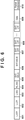
- Fig. 6 shows an example of the PHY (physical) frame structure of a PPDU defined by the IEEE802.11EHT standard and transmitted in step S404 or F504.
- PPDU is an abbreviation of Physical Layer Protocol Data Unit.
- the head portion of the PPDU shown in Fig. 6 includes an L (Legacy)-STF (Short Training Field) 601, an L-LTF (Long Training Field) 602, and an L-SIG (Signal Field) 603 having backward compatibility with the IEEE802.11a/b/g/n/ax standards.
- the L-STF 601 is used for detection of a PHY frame signal, automatic gain control (AGC), timing detection, or the like.
- AGC automatic gain control
- the L-LTF 602 arranged immediately after the L-STF 601 is used for highly accurate frequency/time synchronization, obtainment of propagation channel information (CSI), or the like.
- the L-SIG 603 arranged immediately after the L-LTF 602 is used for transmitting control information including information such as a data transmission rate and a PHY frame length.
- a legacy device complying with the IEEE802.11a/b/g/n/ax standards can decode data of the above-described various kinds of legacy fields (the L-STF 601, the L-LTF 602, and the L-SIG 603).
- the PPDU further includes an RL-SIG 604, an EHT-SIG-A 605, an EHT-SIG-B 606, an EHT-STF 607, an EHT-LTF 608, a data field 609, and a Packet extension 610.
- the RL-SIG 604 may be absent.
- the EHT-SIG-A 605 is arranged after the L-SIG 603, the EHT-SIG-B 606 is arranged immediately after the EHT-SIG-A 605, the EHT-STF 607 is arranged immediately after the EHT-SIG-B 606, the EHT-LTF 608 is arranged immediately after the EHT-STF 607.
- Fig. 6 shows a frame structure having backward compatibility with the IEEE802.11a/b/g/n/ax standards. If backward compatibility need not be ensured, the fields of the L-STF and the L-LTG may be omitted. Instead, the EHT-STF and the EHT-LTF may be inserted.
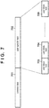
- Fig. 7 shows fields that form the EHT-SIG-B 606.
- the EHT-SIG-B 606 is formed by a Common field 701 and a User specific field 702.
- the User specific field 702 is formed by connecting User Block fields 703, 704, and 705 corresponding to sub-bands each having a bandwidth of 20 MHz.
- Subfields that form the User Block field and a description thereof are shown in Table 1. [Table 1] Subfield Bit Count Description User Block field User field N ⁇ 21 The contents change depending on whether the allocation is Non-MU MIMO allocation or MU MIMO allocation. CRC 4 CRC calculation value Tail 6 Trailer bit, which is set to 0.
- the User field uses a format shown in Table 2 when transmitting data to a plurality of users (STAs) by MU-MIMO.
- Table 2 shows a description of the subfields of the User field when transmitting data by MU-MIMO.
- Spatial Configuration indicates the number of spatial streams (the array of spatial streams) allocated to each STA, and 6 bits are ensured for this subfield.
- Bit Position Subfield Bit Count Description User field B0-B10 STA-ID 11 This subfield indicates the ID of an STA or an STA group that is the receiver of the RU of an HE MU PPDU B11-B16 Spatial Configuration 6 This subfield indicates the number of Spatial Streams of an STA in MU-MIMO Allocation B17-B20 MCS 4 This subfield indicates the value of Modulation and Coding Scheme B21 Reserved 1 Reserved field B22 Coding 1 When BCC (Binary Convolutional Code) is used, "0" is set. When LDPC (Low Density Parity Check) is used, "1" is set.
- BCC Binary Convolutional Code
- LDPC Low Density Parity Check
- the maximum number of spatial streams of MU-MIMO is set to 16, and the upper limit of the number of spatial streams (the number of antennas) held by each STA is set to 4.
- the bit string of the Spatial Configuration subfield indicates the list of the numbers of spatial streams allocated to STAs in a specific number.
- Fig. 8 shows the correspondence between the bit string of the Spatial Configuration subfield and the number of streams of each STA in a case in which the number of STAs is 6.
- the bits of the Spatial Configuration subfield (6 bits) are represented by B5,..., B0 for the description.
- each STA that has received the frame including the subfield grasps the correspondence shown in Fig. 8 and the ID of the STA in the correspondence, thereby detecting, from the frame, the number of spatial streams allocated to the self-STA.
- the number of spatial streams is 1 in all the six STAs. If the Spatial Configuration subfield is "011001", the numbers of spatial streams of the six STAs are 4, 4, 2, 2, 1, and 1. There are a total of 54 patterns of spatial stream arrays. If the number of STAs is less than 6, the number of patterns is less than 54. That is, all patterns of spatial stream arrays can be expressed by 6 bits independently of the number of STAs. Although a detailed correspondence will be omitted, a similar correspondence can be created even if the number of STAs is other than 6.
- a mechanism configured to include, in the PPDU, the information of the spatial stream array in a case in which the number of users (STAs) is 6, the maximum number of spatial streams of MU-MIMO is 16, and the upper limit of the number of spatial streams (the number of antennas) held by each STA is 4. This makes it possible to communicate the information of the spatial stream array between the AP and each STA.
- Table 3 shows a description of the subfields of a User field in an EHT-SIG-B 606 when transmitting data by MU-MIMO.
- Spatial Configuration indicates the number of spatial streams (the array of spatial streams) allocated to each STA, and 8 bits are ensured for this subfield.
- Bit Position Subfield Bit Count Description User field B0-B10 STA-ID 11 This subfield indicates the ID of an STA or an STA group that is the receiver of the RU of an HE MU PPDU B11-B18 Spatial Configuration 8 This subfield indicates the number of Spatial Streams of an STA in MU-MIMO Allocation B19-B22 MCS 4 This subfield indicates the value of Modulation and Coding Scheme B23 Reserved 1 Reserved field B24 Coding 1 When BCC (Binary Convolutional Code) is used, "0" is set. When LDPC (Low Density Parity Check) is used, "1" is set.
- BCC Binary Convolutional Code
- LDPC Low Density Parity Check
- the maximum number of spatial streams of MU-MIMO is set to 16, and the upper limit of the number of spatial streams (the number of antennas) held by each STA is set to 4.
- the bit string of the Spatial Configuration subfield indicates the list of the numbers of spatial streams allocated to STAs in a specific number.
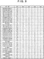
- Fig. 9 shows the correspondence between the bit string of the Spatial Configuration subfield and the number of streams of each STA in a case in which the number of STAs is 8.
- the bits of the Spatial Configuration subfield (8 bits) are represented by B7,..., B0 for the description.
- Nsi indicates the number of antennas of the ith STA, and the spatial streams are allocated such that concerning i > j, "Nsi is always not less than Nsj" holds.
- a mechanism configured to include, in the PPDU, the information of the spatial stream array in a case in which the number of users (STAs) is 5, the maximum number of spatial streams of MU-MIMO is 16, and the upper limit of the number of spatial streams (the number of antennas) held by each STA is 8. This makes it possible to communicate the information of the spatial stream array between the AP and each STA.
- the present invention can be implemented by processing of supplying a program for implementing one or more functions of the above-described embodiments to a system or apparatus via a network or storage medium, and causing one or more processors in the computer of the system or apparatus to read out and execute the program.
- the present invention can also be implemented by a circuit (for example, an ASIC) for implementing one or more functions.
Landscapes
- Engineering & Computer Science (AREA)
- Signal Processing (AREA)
- Computer Networks & Wireless Communication (AREA)
- Power Engineering (AREA)
- Mobile Radio Communication Systems (AREA)
- Communication Control (AREA)
Abstract
Description
- The present invention relates to a communication control technique in a wireless LAN.
- The Internet usage has recently increased year by year along with the development of information communication technologies, and various communication techniques have been developed to cope with an increase in demand. In particular, wireless local area network (wireless LAN) techniques implement throughput improvement in Internet communications for packet data, audio, video, and the like by wireless LAN terminals, and various technological developments have still been conducted actively.
- In the development of wireless LAN techniques, a lot of standardization works by the IEEE (Institute of Electrical and Electronics Engineers) 802, which is a standardization organization for wireless LAN techniques, play an important role. As one of the wireless LAN communication standards, the IEEE802.11 standards are known, including standards such as IEEE802.11n/a/b/g/ac and IEEE802.11ax. For example, IEEE802.11ax implements a high peak throughput of up to 9.6 gigabits per second (Gbps) and additionally improves the communication speed under a congestion situation using OFDMA (Orthogonal frequency-division multiple access) (PTL 1).
- Recently, in order to further improve throughput, a study group called IEEE802.11EHT (Extremely High Throughput) has been formed as a successor standard of IEEE802.11ax. One of measures for throughput improvement that is a target for the IEEE802.11EHT is increasing the number of spatial streams of the MIMO (Multi-Input Milti-Output) method. The MIMO is a method of improving a channel resource use efficiency in a wireless communication network formed by an access point (AP) and a station (STA) that is a wireless LAN terminal by forming a plurality of spatial streams using a plurality of antennas and performing communication. If there is a single STA, the method is called SU-MIMO (Single-User MIMO). If a plurality of STAs exist, the method is called MU-MIMO (Multi-User MIMO). The MIMO has proliferated as a technique for a next-generation communication system in recent years, and is employed in the IEEE802.11 standards as well. For example, in IEEE802.11ax, the method is adaptable to eight spatial streams (SS) at maximum. In IEEE802.11EHT, increasing the maximum number of spatial streams to 16 has been examined. When the number of spatial streams is increased, the space use efficiency further improves, and throughput improvement can be implemented.
- PTL 1:
Japanese Patent Laid-Open No. 2018-50133 - As described above, in the IEEE802.11EHT, the maximum number of spatial streams is assumed to be set to 16. However, in the conventional standards for a wireless LAN, a mechanism that notifies each STA of information concerning allocation of the number of spatial streams in a case in which the total number of spatial streams allocated to one or more STAs (wireless LAN terminals) becomes larger than 8 has not been defined.
- In consideration of the above-described problem, the present invention provides a mechanism configured to notify one or more wireless LAN terminals of allocation of the number of spatial streams, which is larger than 8 in total.
- A communication device according to one aspect of the present invention has the following characteristic features. That is, there is provided
- a communication device including transmission means for transmitting a physical (PHY) frame including a preamble and a data field, characterized in that
- the preamble includes:
- a Legacy Short Training Field (L-STF);
- a Legacy Long Training Field (L-LTF) arranged immediately after the L-STF in the frame;
- a Legacy Signal Field (L-SIG) arranged immediately after the L-LTF in the frame;
- a first EHT (Extremely High Throughput) Signal Field (EHT-SIG-A) arranged after the L-SIG in the frame;
- a second EHT Signal Field (EHT-SIG-B) arranged immediately after the EHT-SIG-A in the frame;
- an EHT Short Training Field (EHT-STF) arranged immediately after the EHT-SIG-B in the frame; and
- an EHT Long Training Field (EHT-LTF) arranged immediately after the EHT-STF in the frame, and
- the EHT-SIG-B includes a subfield indicating the number of spatial streams allocated to each of not less than one other communication device that communicates with the communication device, and the sum of the numbers of spatial streams is larger than 8.
- According to the present invention, there is provided a mechanism configured to notify one or more wireless LAN terminals of allocation of the number of spatial streams, which is larger than 8 in total.
- Other features and advantages of the present invention will be apparent from the following description taken in conjunction with the accompanying drawings. Note that the same reference numerals denote the same or like components throughout the accompanying drawings.
- The accompanying drawings, which are incorporated in and constitute a part of the specification, illustrate embodiments of the invention and, together with the description, serve to explain principles of the invention.
-
Fig. 1 is a view showing an example of the configuration of a network; -
Fig. 2 is a block diagram showing an example of the functional configuration of an AP; -
Fig. 3 is a block diagram showing an example of the hardware configuration of the AP; -
Fig. 4 is a flowchart showing processing executed by the AP; -
Fig. 5 is a sequence chart showing processing executed in a wireless communication network; -
Fig. 6 is a view showing an example of the PHY frame structure of a PPDU used in the embodiment; -
Fig. 7 is a view showing the configuration in an EHT-SIG-B field; -
Fig. 8 is a view showing an example of the correspondence between a Spatial Configuration subfield and the number of spatial streams of each STA; and -
Fig. 9 is a view showing another example of the correspondence between the Spatial Configuration subfield and the number of spatial streams of each STA. - Hereinafter, embodiments will be described in detail with reference to the attached drawings. Note, the following embodiments are not intended to limit the scope of the claimed invention. Multiple features are described in the embodiments, but limitation is not made an invention that requires all such features, and multiple such features may be combined as appropriate. Furthermore, in the attached drawings, the same reference numerals are given to the same or similar configurations, and redundant description thereof is omitted.
-
Fig. 1 shows an example of the configuration of a wireless communication network according to this embodiment. This wireless communication network is configured to include one access point (AP 102) and three STAs (STA 103, STA 104, and STA 105) as devices (EHT devices) complying with the IEEE802.11EHT (Extremely High Throughput) standard. Note that it may be understood that EHT is an acronym of Extremely High Throughput. The AP 102 can be considered as one form of an STA because it has the same functions as theSTAs 103 to 105 except that it has a relay function. STAs located in a circle 101 representing the area where a signal transmitted from the AP 102 reaches can communicate with the AP 102. The AP 102 communicates with theSTAs 103 to 105 in accordance with the wireless communication method of the IEEE802.11EHT standard. The AP 102 can establish a radio link with each of theSTAs 103 to 105 via connection processing such as an association process complying with a standard of the IEEE802.11 series. - Note that the configuration of the wireless communication network shown in
Fig. 1 is merely an example for the description and, for example, a network including many EHT devices and legacy devices (communication devices complying with the IEEE802.11a/b/g/n/ax standards) in a wider area may be formed. Also, the arrangement of the communication devices is not limited to that shown inFig. 1 , and the following argument is applicable to various positional relationships of the communication devices as well. -
Fig. 2 is a block diagram showing the functional configuration of theAP 102. TheAP 102 includes, as an example of its functional configuration, a wirelessLAN control unit 201, aframe generation unit 202, asignal analysis unit 203, and a UI (User Interface)control unit 204. - The wireless
LAN control unit 201 can be configured to include one ormore antennas 205 and circuits configured to transmit/receive a radio signal (radio frame) to/from another wireless LAN device, and a program configured to control these. The wirelessLAN control unit 201 executes communication control of the wireless LAN based on a frame generated by theframe generation unit 202 in accordance with the standard of the IEEE802.11 series. - The
frame generation unit 202 generates a frame to be transmitted by the wirelessLAN control unit 201 based on the result of analysis performed by thesignal analysis unit 203 for a signal received by the wirelessLAN control unit 201. Theframe generation unit 202 may create a frame without depending on the analysis result of thesignal analysis unit 203. Thesignal analysis unit 203 analyzes a signal received by the wirelessLAN control unit 201. TheUI control unit 204 accepts an operation by the user (not shown) of theAP 102 on an input unit 304 (Fig. 3 ), and performs control of transmitting a control signal corresponding to the operation to each constituent element or controls output (including display and the like) for an output unit 305 (Fig. 3 ). -
Fig. 3 shows the hardware configuration of theAP 102 according to this embodiment. TheAP 102 includes, as an example of its hardware configuration, astorage unit 301, acontrol unit 302, afunction unit 303, theinput unit 304, theoutput unit 305, acommunication unit 306, and the one ormore antennas 205. - The
storage unit 301 is formed by both of a ROM and a RAM or one of them, and stores programs for performing various kinds of operations to be described later and various kinds of information such as communication parameters for wireless communication. Note that other than the memories such as a ROM and a RAM, a storage medium such as a flexible disk, a hard disk, an optical disk, a magnetooptical disk, a CD-ROM, a CD-R, a magnetic tape, a nonvolatile memory card, or a DVD may be used as thestorage unit 301. - The
control unit 302 is formed by, for example, a processor such as a CPU or an MPU, an ASIC (Application Specific Integrated Circuit), a DSP (Digital Signal Processor), an FPGA (Field Programmable Gate Array), or the like. Here, CPU is an acronym of Central Processing Unit, and MPU is an acronym of Micro Processing Unit. Thecontrol unit 302 executes the programs stored in thestorage unit 301, thereby controlling theentire AP 102. Note that thecontrol unit 302 may control theentire AP 102 by cooperation of the programs stored in thestorage unit 301 and an OS (Operating System). - In addition, the
control unit 302 controls thefunction unit 303 to execute predetermined processing such as image capturing, printing, or projection. Thefunction unit 303 is hardware used by theAP 102 to execute predetermined processing. For example, if theAP 102 is a camera, thefunction unit 303 is an image capturing unit and performs image capturing processing. For example, if theAP 102 is a printer, thefunction unit 303 is a printing unit and performs print processing. For example, if theAP 102 is a projector, thefunction unit 303 is a projection unit and performs projection processing. Data to be processed by thefunction unit 303 may be data stored in thestorage unit 301, or may be data communicated with an STA or another AP via thecommunication unit 306 to be described later. - The
input unit 304 accepts various kinds of operations from a user. Theoutput unit 305 performs various kinds of outputs for the user. Here, the output by theoutput unit 305 includes at least one of display on a screen, audio output by a loudspeaker, vibration output, and the like. Note that both theinput unit 304 and theoutput unit 305 may be implemented by one module, like a touch panel. - The communication unit 206 controls wireless communication complying with the IEEE802.11EHT standard, or controls wireless communication complying with Wi-Fi or IP (Internet Protocol) communication. Also, the
communication unit 306 controls the one ormore antennas 205 to transmit/receive radio signals for wireless communication. TheAP 102 communicates contents such as image data, document data, and video data with another communication device via thecommunication unit 306. - The functional configuration and the hardware configuration of the
STAs 103 to 105 are the same as the functional configuration (Fig. 2 ) and the hardware configuration (Fig. 3 ) of theAP 102 described above, respectively. That is, each of theSTAs 103 to 105 can be configured to include, as its functional configuration, the wirelessLAN control unit 201, theframe generation unit 202, thesignal analysis unit 203, and theUI control unit 204 and include, as its hardware configuration, thestorage unit 301, thecontrol unit 302, thefunction unit 303, theinput unit 304, theoutput unit 305, thecommunication unit 306, and the one ormore antennas 205. - Next, the procedure of processing executed by the
AP 102 configured as described above and the sequence of processing executed by the wireless communication system shown inFig. 1 will be described with reference toFigs. 4 and 5. Fig. 4 is a flowchart showing processing executed by theAP 102. The flowchart shown inFig. 4 can be implemented when thecontrol unit 302 of theAP 102 executes a control program stored in thestorage unit 301 and executes calculation and processing of information and control of each hardware.Fig. 5 shows a sequence chart of processing executed by the wireless communication system. - The
AP 102 performs connection processing complying with the standard of the IEEE802.11 series for each of theSTAs 103 to 105 (step S401, F501). That is, frames such as Probe Request/Response, Association Request/Response, and Auth (authentication) are transmitted/received between theAP 102 and each of theSTAs 103 to 105, thereby establishing a radio link. Next, theAP 102 decides the number of spatial streams for each of theSTAs 103 to 105. The number of spatial streams for each STA can be decided by thesignal analysis unit 203 based on information concerning the reception state such as CSI (Channel State Information) received from each STA. Also, the number of spatial streams for each STA may be decided in advance in the wireless communication network or may be decided by an operation of the user (not shown) of theAP 102 on theinput unit 304. Next, theAP 102 decides communication parameters including the information concerning the numbers of spatial streams decided in step S402 or F502 and other parameters (information/values), which are included in a radio frame to be transmitted (step S403, F503). Next, theAP 102 transmits data in a form of a radio frame including the decided communication parameters and data to theSTAs 103 to 105 (step S404, F504). -
Fig. 6 shows an example of the PHY (physical) frame structure of a PPDU defined by the IEEE802.11EHT standard and transmitted in step S404 or F504. Note that PPDU is an abbreviation of Physical Layer Protocol Data Unit. The head portion of the PPDU shown inFig. 6 includes an L (Legacy)-STF (Short Training Field) 601, an L-LTF (Long Training Field) 602, and an L-SIG (Signal Field) 603 having backward compatibility with the IEEE802.11a/b/g/n/ax standards. The L-STF 601 is used for detection of a PHY frame signal, automatic gain control (AGC), timing detection, or the like. The L-LTF 602 arranged immediately after the L-STF 601 is used for highly accurate frequency/time synchronization, obtainment of propagation channel information (CSI), or the like. The L-SIG 603 arranged immediately after the L-LTF 602 is used for transmitting control information including information such as a data transmission rate and a PHY frame length. A legacy device complying with the IEEE802.11a/b/g/n/ax standards can decode data of the above-described various kinds of legacy fields (the L-STF 601, the L-LTF 602, and the L-SIG 603). - After the L-
SIG 603, the PPDU further includes an RL-SIG 604, an EHT-SIG-A 605, an EHT-SIG-B 606, an EHT-STF 607, an EHT-LTF 608, adata field 609, and aPacket extension 610. The RL-SIG 604 may be absent. The EHT-SIG-A 605 is arranged after the L-SIG 603, the EHT-SIG-B 606 is arranged immediately after the EHT-SIG-A 605, the EHT-STF 607 is arranged immediately after the EHT-SIG-B 606, the EHT-LTF 608 is arranged immediately after the EHT-STF 607. Note that the field including the L-STF 601, the L-LTF 602, the L-SIG 603, the RL-SIG 604, the EHT-SIG-A 605, the EHT-SIG-B 606, the EHT-STF 607, and the EHT-LTF 608 is called a preamble. Note thatFig. 6 shows a frame structure having backward compatibility with the IEEE802.11a/b/g/n/ax standards. If backward compatibility need not be ensured, the fields of the L-STF and the L-LTG may be omitted. Instead, the EHT-STF and the EHT-LTF may be inserted. -
Fig. 7 shows fields that form the EHT-SIG-B 606. The EHT-SIG-B 606 is formed by aCommon field 701 and a Userspecific field 702. The Userspecific field 702 is formed by connecting User Block fields 703, 704, and 705 corresponding to sub-bands each having a bandwidth of 20 MHz. Subfields that form the User Block field and a description thereof are shown in Table 1.[Table 1] Subfield Bit Count Description User Block field User field N × 21 The contents change depending on whether the allocation is Non-MU MIMO allocation or MU MIMO allocation. CRC 4 CRC calculation value Tail 6 Trailer bit, which is set to 0. - In Table 1, the bit count of the User field is expressed, using an integer N, as N × 21 bits. If the User Block field is the final user block field in the User specific field, and if it holds information of only one user, N = 1. Otherwise, N = 2.
- In the User Block field shown in Table 1, the User field uses a format shown in Table 2 when transmitting data to a plurality of users (STAs) by MU-MIMO. Table 2 shows a description of the subfields of the User field when transmitting data by MU-MIMO. Spatial Configuration indicates the number of spatial streams (the array of spatial streams) allocated to each STA, and 6 bits are ensured for this subfield.
[Table 2] Bit Position Subfield Bit Count Description User field B0-B10 STA-ID 11 This subfield indicates the ID of an STA or an STA group that is the receiver of the RU of an HE MU PPDU B11- B16 Spatial Configuration 6 This subfield indicates the number of Spatial Streams of an STA in MU-MIMO Allocation B17- B20 MCS 4 This subfield indicates the value of Modulation and Coding Scheme B21 Reserved 1 Reserved field B22 Coding 1 When BCC (Binary Convolutional Code) is used, "0" is set. When LDPC (Low Density Parity Check) is used, "1" is set. - In this embodiment, the maximum number of spatial streams of MU-MIMO is set to 16, and the upper limit of the number of spatial streams (the number of antennas) held by each STA is set to 4. The bit string of the Spatial Configuration subfield indicates the list of the numbers of spatial streams allocated to STAs in a specific number. As an example,
Fig. 8 shows the correspondence between the bit string of the Spatial Configuration subfield and the number of streams of each STA in a case in which the number of STAs is 6. - In
Fig. 8 , the bits of the Spatial Configuration subfield (6 bits) are represented by B5,..., B0 for the description. In addition, Nsi indicates the number of antennas of the ith (i = an ID added to an STA) STA, and the spatial streams are allocated such that concerning i > j, "Nsi is always not less than Nsj" holds. Note that each STA that has received the frame including the subfield grasps the correspondence shown inFig. 8 and the ID of the STA in the correspondence, thereby detecting, from the frame, the number of spatial streams allocated to the self-STA.Fig. 8 lists all arrays of spatial streams in a case in which the sum of all Nsi (i = 1, 2, 3, 4, 5, and 6) is 16 or less. For example, if the Spatial Configuration subfield is "000000", the number of spatial streams is 1 in all the six STAs. If the Spatial Configuration subfield is "011001", the numbers of spatial streams of the six STAs are 4, 4, 2, 2, 1, and 1. There are a total of 54 patterns of spatial stream arrays. If the number of STAs is less than 6, the number of patterns is less than 54. That is, all patterns of spatial stream arrays can be expressed by 6 bits independently of the number of STAs. Although a detailed correspondence will be omitted, a similar correspondence can be created even if the number of STAs is other than 6. - As described above, according to this embodiment, when 4 or more bits are ensured for the subfield indicating the number of spatial streams allocated to each STA in the EHT-SIG-B, even if the total number of spatial streams is larger than 8, it is possible to notify each STA of the number of allocated spatial streams. Also, there is provided a mechanism configured to include, in the PPDU, the information of the spatial stream array in a case in which the number of users (STAs) is 6, the maximum number of spatial streams of MU-MIMO is 16, and the upper limit of the number of spatial streams (the number of antennas) held by each STA is 4. This makes it possible to communicate the information of the spatial stream array between the AP and each STA.
- In this embodiment, a case in which the number of users (STAs) is 5, the maximum number of spatial streams of MU-MIMO is 16, and the upper limit of the number of spatial streams (the number of antennas) held by each STA is 8 will be described. Differences from the first embodiment will be described below.
- Table 3 shows a description of the subfields of a User field in an EHT-SIG-
B 606 when transmitting data by MU-MIMO. Spatial Configuration indicates the number of spatial streams (the array of spatial streams) allocated to each STA, and 8 bits are ensured for this subfield.[Table 3] Bit Position Subfield Bit Count Description User field B0-B10 STA-ID 11 This subfield indicates the ID of an STA or an STA group that is the receiver of the RU of an HE MU PPDU B11-B18 Spatial Configuration 8 This subfield indicates the number of Spatial Streams of an STA in MU-MIMO Allocation B19- B22 MCS 4 This subfield indicates the value of Modulation and Coding Scheme B23 Reserved 1 Reserved field B24 Coding 1 When BCC (Binary Convolutional Code) is used, "0" is set. When LDPC (Low Density Parity Check) is used, "1" is set. - In this embodiment, the maximum number of spatial streams of MU-MIMO is set to 16, and the upper limit of the number of spatial streams (the number of antennas) held by each STA is set to 4. The bit string of the Spatial Configuration subfield indicates the list of the numbers of spatial streams allocated to STAs in a specific number.
Fig. 9 shows the correspondence between the bit string of the Spatial Configuration subfield and the number of streams of each STA in a case in which the number of STAs is 8. - In
Fig. 9 , the bits of the Spatial Configuration subfield (8 bits) are represented by B7,..., B0 for the description. In addition, Nsi indicates the number of antennas of the ith STA, and the spatial streams are allocated such that concerning i > j, "Nsi is always not less than Nsj" holds.Fig. 9 lists all arrays of spatial streams in a case in which the sum of all Nsi (i = 1, 2, 3, 4, and 5) is 16 or less. For example, if the Spatial Configuration subfield is "00000000", the number of streams is 1 in all the five STAs. If the Spatial Configuration subfield is "00110110", the numbers of streams of the five STAs are 3, 3, 3, 1, and 1. There are a total of 136 patterns of spatial stream arrays. If the number of STAs is less than 5, the number of patterns is less than 136. That is, all patterns can be expressed by 8 bits independently of the number of STAs. Although a detailed correspondence will be omitted, a similar correspondence can be created even if the number of STAs is other than 5. - As described above, according to this embodiment, there is provided a mechanism configured to include, in the PPDU, the information of the spatial stream array in a case in which the number of users (STAs) is 5, the maximum number of spatial streams of MU-MIMO is 16, and the upper limit of the number of spatial streams (the number of antennas) held by each STA is 8. This makes it possible to communicate the information of the spatial stream array between the AP and each STA.
- The present invention can be implemented by processing of supplying a program for implementing one or more functions of the above-described embodiments to a system or apparatus via a network or storage medium, and causing one or more processors in the computer of the system or apparatus to read out and execute the program. The present invention can also be implemented by a circuit (for example, an ASIC) for implementing one or more functions.
- The present invention is not limited to the above embodiments and various changes and modifications can be made within the spirit and scope of the present invention. Therefore, to apprise the public of the scope of the present invention, the following claims are made.
- This application claims priority from
Japanese Patent Application No. 2019-036403 filed February 28, 2019
Claims (9)
- A communication device including transmission means for transmitting a physical (PHY) frame including a preamble and a data field, characterized in thatthe preamble includes:a Legacy Short Training Field (L-STF);a Legacy Long Training Field (L-LTF) arranged immediately after the L-STF in the frame;a Legacy Signal Field (L-SIG) arranged immediately after the L-LTF in the frame;a first EHT (Extremely High Throughput) Signal Field (EHT-SIG-A) arranged after the L-SIG in the frame;a second EHT Signal Field (EHT-SIG-B) arranged immediately after the EHT-SIG-A in the frame;an EHT Short Training Field (EHT-STF) arranged immediately after the EHT-SIG-B in the frame; andan EHT Long Training Field (EHT-LTF) arranged immediately after the EHT-STF in the frame, andthe EHT-SIG-B includes a subfield indicating the number of spatial streams allocated to each of not less than one other communication device that communicates with the communication device, and the sum of the numbers of spatial streams is larger than 8.
- A communication device including reception means for receiving a physical (PHY) frame including a preamble and a data field, characterized in thatthe preamble includes:a Legacy Short Training Field (L-STF);a Legacy Long Training Field (L-LTF) arranged immediately after the L-STF in the frame;a Legacy Signal Field (L-SIG) arranged immediately after the L-LTF in the frame;a first EHT (Extremely High Throughput) Signal Field (EHT-SIG-A) arranged after the L-SIG in the frame;a second EHT Signal Field (EHT-SIG-B) arranged immediately after the EHT-SIG-A in the frame;an EHT Short Training Field (EHT-STF) arranged immediately after the EHT-SIG-B in the frame; andan EHT Long Training Field (EHT-LTF) arranged immediately after the EHT-STF in the frame, andthe EHT-SIG-B includes a subfield indicating the number of spatial streams allocated to the communication device to communicate with another communication device, and the subfield is formed by not less than 4 bits.
- The communication device according to claim 1 or 2, characterized in that the subfield is a 6-bit Spatial Configuration subfield included in a User field.
- The communication device according to claim 1 or 2, characterized in that the subfield is an 8-bit Spatial Configuration subfield included in a User field.
- A control method of a communication device including transmission means for transmitting a physical (PHY) frame including a preamble and a data field, characterized in thatthe preamble includes:a Legacy Short Training Field (L-STF);a Legacy Long Training Field (L-LTF) arranged immediately after the L-STF in the frame;a Legacy Signal Field (L-SIG) arranged immediately after the L-LTF in the frame;a first EHT (Extremely High Throughput) Signal Field (EHT-SIG-A) arranged after the L-SIG in the frame;a second EHT Signal Field (EHT-SIG-B) arranged immediately after the EHT-SIG-A in the frame;an EHT Short Training Field (EHT-STF) arranged immediately after the EHT-SIG-B in the frame; andan EHT Long Training Field (EHT-LTF) arranged immediately after the EHT-STF in the frame, andthe EHT-SIG-B includes a subfield indicating the number of spatial streams allocated to each of not less than one other communication device that communicates with the communication device, and the sum of the numbers of spatial streams is larger than 8.
- A control method of a communication device including reception means for receiving a physical (PHY) frame including a preamble and a data field, characterized in thatthe preamble includes:a Legacy Short Training Field (L-STF);a Legacy Long Training Field (L-LTF) arranged immediately after the L-STF in the frame;a Legacy Signal Field (L-SIG) arranged immediately after the L-LTF in the frame;a first EHT (Extremely High Throughput) Signal Field (EHT-SIG-A) arranged after the L-SIG in the frame;a second EHT Signal Field (EHT-SIG-B) arranged immediately after the EHT-SIG-A in the frame;an EHT Short Training Field (EHT-STF) arranged immediately after the EHT-SIG-B in the frame; andan EHT Long Training Field (EHT-LTF) arranged immediately after the EHT-STF in the frame, andthe EHT-SIG-B includes a subfield indicating the number of spatial streams allocated to the communication device to communicate with another communication device, and the subfield is formed by not less than 4 bits.
- The control method of the communication device according to claim 5 or 6, characterized in that the subfield is a 6-bit Spatial Configuration subfield included in a User field.
- The control method of the communication device according to claim 5 or 6, characterized in that the subfield is an 8-bit Spatial Configuration subfield included in a User field.
- A program configured to cause a computer to function as a communication device defined in any one of claims 1 to 4.
Priority Applications (1)
| Application Number | Priority Date | Filing Date | Title |
|---|---|---|---|
| EP24212025.1A EP4498628A3 (en) | 2019-02-28 | 2020-02-05 | Communication device, control method for communication device, and program |
Applications Claiming Priority (2)
| Application Number | Priority Date | Filing Date | Title |
|---|---|---|---|
| JP2019036403A JP2020141301A (en) | 2019-02-28 | 2019-02-28 | Communication device, communication method of communication device, and program |
| PCT/JP2020/004214 WO2020175043A1 (en) | 2019-02-28 | 2020-02-05 | Communication device, control method for communication device, and program |
Related Child Applications (1)
| Application Number | Title | Priority Date | Filing Date |
|---|---|---|---|
| EP24212025.1A Division EP4498628A3 (en) | 2019-02-28 | 2020-02-05 | Communication device, control method for communication device, and program |
Publications (3)
| Publication Number | Publication Date |
|---|---|
| EP3934307A1 true EP3934307A1 (en) | 2022-01-05 |
| EP3934307A4 EP3934307A4 (en) | 2022-11-16 |
| EP3934307B1 EP3934307B1 (en) | 2024-12-11 |
Family
ID=72239855
Family Applications (2)
| Application Number | Title | Priority Date | Filing Date |
|---|---|---|---|
| EP20763969.1A Active EP3934307B1 (en) | 2019-02-28 | 2020-02-05 | Communication device, control method for communication device, and program |
| EP24212025.1A Pending EP4498628A3 (en) | 2019-02-28 | 2020-02-05 | Communication device, control method for communication device, and program |
Family Applications After (1)
| Application Number | Title | Priority Date | Filing Date |
|---|---|---|---|
| EP24212025.1A Pending EP4498628A3 (en) | 2019-02-28 | 2020-02-05 | Communication device, control method for communication device, and program |
Country Status (10)
| Country | Link |
|---|---|
| US (1) | US20210385110A1 (en) |
| EP (2) | EP3934307B1 (en) |
| JP (2) | JP2020141301A (en) |
| KR (2) | KR20240116567A (en) |
| CN (2) | CN113597783B (en) |
| BR (1) | BR112021016415A2 (en) |
| ES (1) | ES3006436T3 (en) |
| FI (1) | FI3934307T3 (en) |
| PH (1) | PH12021552052A1 (en) |
| WO (1) | WO2020175043A1 (en) |
Families Citing this family (2)
| Publication number | Priority date | Publication date | Assignee | Title |
|---|---|---|---|---|
| US11616547B2 (en) * | 2020-05-26 | 2023-03-28 | Mediatek Singapore Pte. Ltd. | Spatial configuration subfield designs of user field for MU-MIMO allocation in extreme-high-throughput systems |
| EP4338548A4 (en) * | 2021-06-24 | 2024-07-24 | Guangdong Oppo Mobile Telecommunications Corp., Ltd. | ACCESS POINT, STATION AND WIRELESS COMMUNICATION METHODS |
Family Cites Families (19)
| Publication number | Priority date | Publication date | Assignee | Title |
|---|---|---|---|---|
| US10231215B2 (en) * | 2014-08-07 | 2019-03-12 | Lg Electronics Inc. | Multi-user transmission method in wireless communication system and device therefor |
| AU2015304131B2 (en) * | 2014-08-21 | 2018-08-02 | Lg Electronics Inc. | Method for uplink transmission in wireless communication system and apparatus therefor |
| US9826532B1 (en) * | 2015-02-09 | 2017-11-21 | Marvell International Ltd. | Orthogonal frequency division multiple access resource request |
| WO2016175614A1 (en) * | 2015-04-29 | 2016-11-03 | 엘지전자 주식회사 | Method for transmitting and receiving confirmation response signal for uplink multi-user data in wireless lan system, and apparatus therefor |
| WO2016200020A1 (en) * | 2015-06-11 | 2016-12-15 | 엘지전자 주식회사 | Method for transmitting and receiving signal in wireless lan system and apparatus therefor |
| US10523361B2 (en) * | 2015-07-07 | 2019-12-31 | Lg Electronics Inc. | Method for operating sounding in wireless LAN system, and apparatus therefor |
| JP6437109B2 (en) * | 2015-08-06 | 2018-12-12 | エルジー エレクトロニクス インコーポレイティド | Method and apparatus for generating a training signal using a preset binary sequence in a wireless LAN system |
| KR102213184B1 (en) * | 2015-08-10 | 2021-02-05 | 엘지전자 주식회사 | Method and apparatus for configuring a control signal including a control field in a wireless LAN system |
| CN108432173B (en) * | 2015-12-21 | 2021-05-28 | 高通股份有限公司 | Method and apparatus for wireless communication |
| JP2018050133A (en) | 2016-09-20 | 2018-03-29 | キヤノン株式会社 | Communication device, control method, and program |
| KR102155707B1 (en) | 2016-11-04 | 2020-09-14 | 주식회사 엘지화학 | Electrode assembly and the manufacturing method |
| JP6966255B2 (en) | 2017-08-10 | 2021-11-10 | 株式会社ニューフレアテクノロジー | How to adjust the optical system of the image acquisition device |
| US10365362B2 (en) * | 2017-09-11 | 2019-07-30 | Intel IP Corporation | Location measurement reporting |
| WO2019182427A1 (en) * | 2018-03-23 | 2019-09-26 | 엘지전자 주식회사 | Method and apparatus for transmitting data over nccb in wireless lan system |
| US11272490B2 (en) * | 2018-06-01 | 2022-03-08 | Qualcomm Incorporated | Techniques for control signaling in extreme high throughput environments |
| SG10201807233SA (en) * | 2018-08-24 | 2020-03-30 | Panasonic Ip Corp America | Communication apparatus and communication method for control signaling |
| US10813061B2 (en) * | 2018-09-18 | 2020-10-20 | Intel Corporation | Power reduction in a wireless network |
| US11165544B2 (en) * | 2018-10-04 | 2021-11-02 | Qualcomm Incorporated | Multi-user preamble format for a wireless local area network |
| WO2020080786A1 (en) * | 2018-10-15 | 2020-04-23 | 엘지전자 주식회사 | Signaling method related to spatial stream for wireless communication |
-
2019
- 2019-02-28 JP JP2019036403A patent/JP2020141301A/en active Pending
-
2020
- 2020-02-05 PH PH1/2021/552052A patent/PH12021552052A1/en unknown
- 2020-02-05 ES ES20763969T patent/ES3006436T3/en active Active
- 2020-02-05 CN CN202080017351.7A patent/CN113597783B/en active Active
- 2020-02-05 FI FIEP20763969.1T patent/FI3934307T3/en active
- 2020-02-05 KR KR1020247023901A patent/KR20240116567A/en active Pending
- 2020-02-05 EP EP20763969.1A patent/EP3934307B1/en active Active
- 2020-02-05 CN CN202410626681.6A patent/CN118573338A/en active Pending
- 2020-02-05 KR KR1020217028957A patent/KR20210122851A/en not_active Ceased
- 2020-02-05 WO PCT/JP2020/004214 patent/WO2020175043A1/en not_active Ceased
- 2020-02-05 BR BR112021016415-4A patent/BR112021016415A2/en unknown
- 2020-02-05 EP EP24212025.1A patent/EP4498628A3/en active Pending
-
2021
- 2021-08-24 US US17/409,839 patent/US20210385110A1/en not_active Abandoned
-
2023
- 2023-11-09 JP JP2023191716A patent/JP7724827B2/en active Active
Also Published As
| Publication number | Publication date |
|---|---|
| KR20240116567A (en) | 2024-07-29 |
| JP2023184728A (en) | 2023-12-28 |
| CN113597783A (en) | 2021-11-02 |
| ES3006436T3 (en) | 2025-03-18 |
| CN113597783B (en) | 2024-05-31 |
| FI3934307T3 (en) | 2025-02-27 |
| EP3934307B1 (en) | 2024-12-11 |
| WO2020175043A1 (en) | 2020-09-03 |
| EP3934307A4 (en) | 2022-11-16 |
| EP4498628A2 (en) | 2025-01-29 |
| PH12021552052A1 (en) | 2022-07-11 |
| CN118573338A (en) | 2024-08-30 |
| KR20210122851A (en) | 2021-10-12 |
| US20210385110A1 (en) | 2021-12-09 |
| EP4498628A3 (en) | 2025-04-30 |
| BR112021016415A2 (en) | 2021-10-13 |
| JP7724827B2 (en) | 2025-08-18 |
| JP2020141301A (en) | 2020-09-03 |
Similar Documents
| Publication | Publication Date | Title |
|---|---|---|
| CN113491089B (en) | Communication device, information processing device, communication method, and computer-readable storage medium | |
| US11612014B2 (en) | Communication device, communication method thereof, information processing device, control method thereof, and storage medium | |
| US12549416B2 (en) | Communication device, communication method, and computer-readable storage medium | |
| US20240305505A1 (en) | Communication device, communication method thereof, information processing device, control method thereof, and computer-readable storage medium | |
| JP7600303B2 (en) | COMMUNICATION DEVICE AND ITS COMMUNICATION METHOD, INFORMATION PROCESSING DEVICE AND ITS CONTROL METHOD, AND PROGRAM | |
| US20250240054A1 (en) | Communication device, communication method, and storage medium | |
| JP2023053119A (en) | Communication device, communication method, and program | |
| JP7724827B2 (en) | COMMUNICATION DEVICE, COMMUNICATION METHOD FOR COMMUNICATION DEVICE, AND PROGRAM | |
| US20260142854A1 (en) | Communication device, communication method, and computer-readable storage medium |
Legal Events
| Date | Code | Title | Description |
|---|---|---|---|
| STAA | Information on the status of an ep patent application or granted ep patent |
Free format text: STATUS: THE INTERNATIONAL PUBLICATION HAS BEEN MADE |
|
| PUAI | Public reference made under article 153(3) epc to a published international application that has entered the european phase |
Free format text: ORIGINAL CODE: 0009012 |
|
| STAA | Information on the status of an ep patent application or granted ep patent |
Free format text: STATUS: REQUEST FOR EXAMINATION WAS MADE |
|
| 17P | Request for examination filed |
Effective date: 20210928 |
|
| AK | Designated contracting states |
Kind code of ref document: A1 Designated state(s): AL AT BE BG CH CY CZ DE DK EE ES FI FR GB GR HR HU IE IS IT LI LT LU LV MC MK MT NL NO PL PT RO RS SE SI SK SM TR |
|
| DAV | Request for validation of the european patent (deleted) | ||
| DAX | Request for extension of the european patent (deleted) | ||
| REG | Reference to a national code |
Ref country code: DE Ref legal event code: R079 Free format text: PREVIOUS MAIN CLASS: H04W0016280000 Ipc: H04L0027260000 Ref country code: DE Ref legal event code: R079 Ref document number: 602020042995 Country of ref document: DE Free format text: PREVIOUS MAIN CLASS: H04W0016280000 Ipc: H04L0027260000 |
|
| A4 | Supplementary search report drawn up and despatched |
Effective date: 20221014 |
|
| RIC1 | Information provided on ipc code assigned before grant |
Ipc: H04L 5/00 20060101ALI20221010BHEP Ipc: H04B 7/0452 20170101ALI20221010BHEP Ipc: H04L 27/26 20060101AFI20221010BHEP |
|
| STAA | Information on the status of an ep patent application or granted ep patent |
Free format text: STATUS: EXAMINATION IS IN PROGRESS |
|
| 17Q | First examination report despatched |
Effective date: 20230728 |
|
| GRAP | Despatch of communication of intention to grant a patent |
Free format text: ORIGINAL CODE: EPIDOSNIGR1 |
|
| STAA | Information on the status of an ep patent application or granted ep patent |
Free format text: STATUS: GRANT OF PATENT IS INTENDED |
|
| INTG | Intention to grant announced |
Effective date: 20240207 |
|
| GRAJ | Information related to disapproval of communication of intention to grant by the applicant or resumption of examination proceedings by the epo deleted |
Free format text: ORIGINAL CODE: EPIDOSDIGR1 |
|
| STAA | Information on the status of an ep patent application or granted ep patent |
Free format text: STATUS: EXAMINATION IS IN PROGRESS |
|
| GRAP | Despatch of communication of intention to grant a patent |
Free format text: ORIGINAL CODE: EPIDOSNIGR1 |
|
| STAA | Information on the status of an ep patent application or granted ep patent |
Free format text: STATUS: GRANT OF PATENT IS INTENDED |
|
| INTC | Intention to grant announced (deleted) | ||
| INTG | Intention to grant announced |
Effective date: 20240701 |
|
| GRAS | Grant fee paid |
Free format text: ORIGINAL CODE: EPIDOSNIGR3 |
|
| GRAA | (expected) grant |
Free format text: ORIGINAL CODE: 0009210 |
|
| STAA | Information on the status of an ep patent application or granted ep patent |
Free format text: STATUS: THE PATENT HAS BEEN GRANTED |
|
| P01 | Opt-out of the competence of the unified patent court (upc) registered |
Free format text: CASE NUMBER: APP_59191/2024 Effective date: 20241030 |
|
| AK | Designated contracting states |
Kind code of ref document: B1 Designated state(s): AL AT BE BG CH CY CZ DE DK EE ES FI FR GB GR HR HU IE IS IT LI LT LU LV MC MK MT NL NO PL PT RO RS SE SI SK SM TR |
|
| REG | Reference to a national code |
Ref country code: GB Ref legal event code: FG4D |
|
| REG | Reference to a national code |
Ref country code: CH Ref legal event code: EP |
|
| REG | Reference to a national code |
Ref country code: DE Ref legal event code: R096 Ref document number: 602020042995 Country of ref document: DE |
|
| REG | Reference to a national code |
Ref country code: IE Ref legal event code: FG4D |
|
| REG | Reference to a national code |
Ref country code: SE Ref legal event code: TRGR |
|
| REG | Reference to a national code |
Ref country code: NL Ref legal event code: FP |
|
| REG | Reference to a national code |
Ref country code: FI Ref legal event code: FGE |
|
| REG | Reference to a national code |
Ref country code: ES Ref legal event code: FG2A Ref document number: 3006436 Country of ref document: ES Kind code of ref document: T3 Effective date: 20250318 |
|
| REG | Reference to a national code |
Ref country code: LT Ref legal event code: MG9D |
|
| PG25 | Lapsed in a contracting state [announced via postgrant information from national office to epo] |
Ref country code: HR Free format text: LAPSE BECAUSE OF FAILURE TO SUBMIT A TRANSLATION OF THE DESCRIPTION OR TO PAY THE FEE WITHIN THE PRESCRIBED TIME-LIMIT Effective date: 20241211 |
|
| PG25 | Lapsed in a contracting state [announced via postgrant information from national office to epo] |
Ref country code: BG Free format text: LAPSE BECAUSE OF FAILURE TO SUBMIT A TRANSLATION OF THE DESCRIPTION OR TO PAY THE FEE WITHIN THE PRESCRIBED TIME-LIMIT Effective date: 20241211 |
|
| PG25 | Lapsed in a contracting state [announced via postgrant information from national office to epo] |
Ref country code: LV Free format text: LAPSE BECAUSE OF FAILURE TO SUBMIT A TRANSLATION OF THE DESCRIPTION OR TO PAY THE FEE WITHIN THE PRESCRIBED TIME-LIMIT Effective date: 20241211 Ref country code: GR Free format text: LAPSE BECAUSE OF FAILURE TO SUBMIT A TRANSLATION OF THE DESCRIPTION OR TO PAY THE FEE WITHIN THE PRESCRIBED TIME-LIMIT Effective date: 20250312 |
|
| PG25 | Lapsed in a contracting state [announced via postgrant information from national office to epo] |
Ref country code: RS Free format text: LAPSE BECAUSE OF FAILURE TO SUBMIT A TRANSLATION OF THE DESCRIPTION OR TO PAY THE FEE WITHIN THE PRESCRIBED TIME-LIMIT Effective date: 20250311 |
|
| REG | Reference to a national code |
Ref country code: AT Ref legal event code: MK05 Ref document number: 1751241 Country of ref document: AT Kind code of ref document: T Effective date: 20241211 |
|
| PG25 | Lapsed in a contracting state [announced via postgrant information from national office to epo] |
Ref country code: SM Free format text: LAPSE BECAUSE OF FAILURE TO SUBMIT A TRANSLATION OF THE DESCRIPTION OR TO PAY THE FEE WITHIN THE PRESCRIBED TIME-LIMIT Effective date: 20241211 |
|
| PG25 | Lapsed in a contracting state [announced via postgrant information from national office to epo] |
Ref country code: PL Free format text: LAPSE BECAUSE OF FAILURE TO SUBMIT A TRANSLATION OF THE DESCRIPTION OR TO PAY THE FEE WITHIN THE PRESCRIBED TIME-LIMIT Effective date: 20241211 |
|
| PG25 | Lapsed in a contracting state [announced via postgrant information from national office to epo] |
Ref country code: IS Free format text: LAPSE BECAUSE OF FAILURE TO SUBMIT A TRANSLATION OF THE DESCRIPTION OR TO PAY THE FEE WITHIN THE PRESCRIBED TIME-LIMIT Effective date: 20250411 |
|
| PG25 | Lapsed in a contracting state [announced via postgrant information from national office to epo] |
Ref country code: PT Free format text: LAPSE BECAUSE OF FAILURE TO SUBMIT A TRANSLATION OF THE DESCRIPTION OR TO PAY THE FEE WITHIN THE PRESCRIBED TIME-LIMIT Effective date: 20250411 |
|
| PG25 | Lapsed in a contracting state [announced via postgrant information from national office to epo] |
Ref country code: EE Free format text: LAPSE BECAUSE OF FAILURE TO SUBMIT A TRANSLATION OF THE DESCRIPTION OR TO PAY THE FEE WITHIN THE PRESCRIBED TIME-LIMIT Effective date: 20241211 |
|
| PG25 | Lapsed in a contracting state [announced via postgrant information from national office to epo] |
Ref country code: AT Free format text: LAPSE BECAUSE OF FAILURE TO SUBMIT A TRANSLATION OF THE DESCRIPTION OR TO PAY THE FEE WITHIN THE PRESCRIBED TIME-LIMIT Effective date: 20241211 Ref country code: RO Free format text: LAPSE BECAUSE OF FAILURE TO SUBMIT A TRANSLATION OF THE DESCRIPTION OR TO PAY THE FEE WITHIN THE PRESCRIBED TIME-LIMIT Effective date: 20241211 |
|
| PG25 | Lapsed in a contracting state [announced via postgrant information from national office to epo] |
Ref country code: SK Free format text: LAPSE BECAUSE OF FAILURE TO SUBMIT A TRANSLATION OF THE DESCRIPTION OR TO PAY THE FEE WITHIN THE PRESCRIBED TIME-LIMIT Effective date: 20241211 |
|
| PG25 | Lapsed in a contracting state [announced via postgrant information from national office to epo] |
Ref country code: CZ Free format text: LAPSE BECAUSE OF FAILURE TO SUBMIT A TRANSLATION OF THE DESCRIPTION OR TO PAY THE FEE WITHIN THE PRESCRIBED TIME-LIMIT Effective date: 20241211 |
|
| REG | Reference to a national code |
Ref country code: DE Ref legal event code: R097 Ref document number: 602020042995 Country of ref document: DE |
|
| PG25 | Lapsed in a contracting state [announced via postgrant information from national office to epo] |
Ref country code: MC Free format text: LAPSE BECAUSE OF FAILURE TO SUBMIT A TRANSLATION OF THE DESCRIPTION OR TO PAY THE FEE WITHIN THE PRESCRIBED TIME-LIMIT Effective date: 20241211 |
|
| REG | Reference to a national code |
Ref country code: CH Ref legal event code: PL |
|
| PG25 | Lapsed in a contracting state [announced via postgrant information from national office to epo] |
Ref country code: DK Free format text: LAPSE BECAUSE OF FAILURE TO SUBMIT A TRANSLATION OF THE DESCRIPTION OR TO PAY THE FEE WITHIN THE PRESCRIBED TIME-LIMIT Effective date: 20241211 |
|
| PG25 | Lapsed in a contracting state [announced via postgrant information from national office to epo] |
Ref country code: LU Free format text: LAPSE BECAUSE OF NON-PAYMENT OF DUE FEES Effective date: 20250205 |
|
| PLBE | No opposition filed within time limit |
Free format text: ORIGINAL CODE: 0009261 |
|
| STAA | Information on the status of an ep patent application or granted ep patent |
Free format text: STATUS: NO OPPOSITION FILED WITHIN TIME LIMIT |
|
| PG25 | Lapsed in a contracting state [announced via postgrant information from national office to epo] |
Ref country code: CH Free format text: LAPSE BECAUSE OF NON-PAYMENT OF DUE FEES Effective date: 20250228 |
|
| 26N | No opposition filed |
Effective date: 20250912 |
|
| REG | Reference to a national code |
Ref country code: BE Ref legal event code: MM Effective date: 20250228 |
|
| PG25 | Lapsed in a contracting state [announced via postgrant information from national office to epo] |
Ref country code: BE Free format text: LAPSE BECAUSE OF NON-PAYMENT OF DUE FEES Effective date: 20250228 |
|
| PG25 | Lapsed in a contracting state [announced via postgrant information from national office to epo] |
Ref country code: IE Free format text: LAPSE BECAUSE OF NON-PAYMENT OF DUE FEES Effective date: 20250205 |
|
| PGFP | Annual fee paid to national office [announced via postgrant information from national office to epo] |
Ref country code: NL Payment date: 20260121 Year of fee payment: 7 |
|
| PGFP | Annual fee paid to national office [announced via postgrant information from national office to epo] |
Ref country code: SE Payment date: 20260121 Year of fee payment: 7 |
|
| PGFP | Annual fee paid to national office [announced via postgrant information from national office to epo] |
Ref country code: GB Payment date: 20260121 Year of fee payment: 7 |
|
| PGFP | Annual fee paid to national office [announced via postgrant information from national office to epo] |
Ref country code: ES Payment date: 20260302 Year of fee payment: 7 |
|
| PGFP | Annual fee paid to national office [announced via postgrant information from national office to epo] |
Ref country code: DE Payment date: 20260121 Year of fee payment: 7 Ref country code: NO Payment date: 20260123 Year of fee payment: 7 |
|
| PGFP | Annual fee paid to national office [announced via postgrant information from national office to epo] |
Ref country code: FI Payment date: 20260121 Year of fee payment: 7 Ref country code: IT Payment date: 20260121 Year of fee payment: 7 |
|
| PGFP | Annual fee paid to national office [announced via postgrant information from national office to epo] |
Ref country code: FR Payment date: 20260121 Year of fee payment: 7 |