EP3934038A1 - Thermal expansion slide with cable clamp - Google Patents
Thermal expansion slide with cable clamp Download PDFInfo
- Publication number
- EP3934038A1 EP3934038A1 EP21182500.5A EP21182500A EP3934038A1 EP 3934038 A1 EP3934038 A1 EP 3934038A1 EP 21182500 A EP21182500 A EP 21182500A EP 3934038 A1 EP3934038 A1 EP 3934038A1
- Authority
- EP
- European Patent Office
- Prior art keywords
- clamp
- management system
- cable
- cable management
- attach
- Prior art date
- Legal status (The legal status is an assumption and is not a legal conclusion. Google has not performed a legal analysis and makes no representation as to the accuracy of the status listed.)
- Pending
Links
- 238000009434 installation Methods 0.000 claims abstract description 17
- 230000006835 compression Effects 0.000 claims description 50
- 238000007906 compression Methods 0.000 claims description 50
- 229920000642 polymer Polymers 0.000 claims description 6
- 230000008602 contraction Effects 0.000 abstract description 5
- 230000003466 anti-cipated effect Effects 0.000 abstract description 3
- 230000007246 mechanism Effects 0.000 description 3
- 230000004308 accommodation Effects 0.000 description 2
- 230000006872 improvement Effects 0.000 description 2
- 238000009413 insulation Methods 0.000 description 2
- 239000002184 metal Substances 0.000 description 2
- 238000000034 method Methods 0.000 description 2
- 239000004020 conductor Substances 0.000 description 1
- 238000005260 corrosion Methods 0.000 description 1
- 230000007797 corrosion Effects 0.000 description 1
- 239000013013 elastic material Substances 0.000 description 1
- 229920001971 elastomer Polymers 0.000 description 1
- 238000011900 installation process Methods 0.000 description 1
- 239000000463 material Substances 0.000 description 1
- 239000007769 metal material Substances 0.000 description 1
- 230000004048 modification Effects 0.000 description 1
- 238000012986 modification Methods 0.000 description 1
- 230000008569 process Effects 0.000 description 1
- 229920002725 thermoplastic elastomer Polymers 0.000 description 1
Images



Classifications
-
- H—ELECTRICITY
- H01—ELECTRIC ELEMENTS
- H01B—CABLES; CONDUCTORS; INSULATORS; SELECTION OF MATERIALS FOR THEIR CONDUCTIVE, INSULATING OR DIELECTRIC PROPERTIES
- H01B7/00—Insulated conductors or cables characterised by their form
- H01B7/0045—Cable-harnesses
-
- H—ELECTRICITY
- H02—GENERATION; CONVERSION OR DISTRIBUTION OF ELECTRIC POWER
- H02G—INSTALLATION OF ELECTRIC CABLES OR LINES, OR OF COMBINED OPTICAL AND ELECTRIC CABLES OR LINES
- H02G3/00—Installations of electric cables or lines or protective tubing therefor in or on buildings, equivalent structures or vehicles
- H02G3/02—Details
- H02G3/04—Protective tubing or conduits, e.g. cable ladders or cable troughs
- H02G3/0493—Service poles
-
- F—MECHANICAL ENGINEERING; LIGHTING; HEATING; WEAPONS; BLASTING
- F16—ENGINEERING ELEMENTS AND UNITS; GENERAL MEASURES FOR PRODUCING AND MAINTAINING EFFECTIVE FUNCTIONING OF MACHINES OR INSTALLATIONS; THERMAL INSULATION IN GENERAL
- F16B—DEVICES FOR FASTENING OR SECURING CONSTRUCTIONAL ELEMENTS OR MACHINE PARTS TOGETHER, e.g. NAILS, BOLTS, CIRCLIPS, CLAMPS, CLIPS OR WEDGES; JOINTS OR JOINTING
- F16B7/00—Connections of rods or tubes, e.g. of non-circular section, mutually, including resilient connections
- F16B7/18—Connections of rods or tubes, e.g. of non-circular section, mutually, including resilient connections using screw-thread elements
- F16B7/187—Connections of rods or tubes, e.g. of non-circular section, mutually, including resilient connections using screw-thread elements with sliding nuts or other additional connecting members for joining profiles provided with grooves or channels
-
- F—MECHANICAL ENGINEERING; LIGHTING; HEATING; WEAPONS; BLASTING
- F16—ENGINEERING ELEMENTS AND UNITS; GENERAL MEASURES FOR PRODUCING AND MAINTAINING EFFECTIVE FUNCTIONING OF MACHINES OR INSTALLATIONS; THERMAL INSULATION IN GENERAL
- F16F—SPRINGS; SHOCK-ABSORBERS; MEANS FOR DAMPING VIBRATION
- F16F1/00—Springs
- F16F1/02—Springs made of steel or other material having low internal friction; Wound, torsion, leaf, cup, ring or the like springs, the material of the spring not being relevant
- F16F1/04—Wound springs
- F16F1/12—Attachments or mountings
-
- F—MECHANICAL ENGINEERING; LIGHTING; HEATING; WEAPONS; BLASTING
- F16—ENGINEERING ELEMENTS AND UNITS; GENERAL MEASURES FOR PRODUCING AND MAINTAINING EFFECTIVE FUNCTIONING OF MACHINES OR INSTALLATIONS; THERMAL INSULATION IN GENERAL
- F16L—PIPES; JOINTS OR FITTINGS FOR PIPES; SUPPORTS FOR PIPES, CABLES OR PROTECTIVE TUBING; MEANS FOR THERMAL INSULATION IN GENERAL
- F16L3/00—Supports for pipes, cables or protective tubing, e.g. hangers, holders, clamps, cleats, clips, brackets
- F16L3/08—Supports for pipes, cables or protective tubing, e.g. hangers, holders, clamps, cleats, clips, brackets substantially surrounding the pipe, cable or protective tubing
- F16L3/10—Supports for pipes, cables or protective tubing, e.g. hangers, holders, clamps, cleats, clips, brackets substantially surrounding the pipe, cable or protective tubing divided, i.e. with two members engaging the pipe, cable or protective tubing
- F16L3/1091—Supports for pipes, cables or protective tubing, e.g. hangers, holders, clamps, cleats, clips, brackets substantially surrounding the pipe, cable or protective tubing divided, i.e. with two members engaging the pipe, cable or protective tubing with two members, the two members being fixed to each other with fastening members on each side
-
- F—MECHANICAL ENGINEERING; LIGHTING; HEATING; WEAPONS; BLASTING
- F16—ENGINEERING ELEMENTS AND UNITS; GENERAL MEASURES FOR PRODUCING AND MAINTAINING EFFECTIVE FUNCTIONING OF MACHINES OR INSTALLATIONS; THERMAL INSULATION IN GENERAL
- F16L—PIPES; JOINTS OR FITTINGS FOR PIPES; SUPPORTS FOR PIPES, CABLES OR PROTECTIVE TUBING; MEANS FOR THERMAL INSULATION IN GENERAL
- F16L3/00—Supports for pipes, cables or protective tubing, e.g. hangers, holders, clamps, cleats, clips, brackets
- F16L3/16—Supports for pipes, cables or protective tubing, e.g. hangers, holders, clamps, cleats, clips, brackets with special provision allowing movement of the pipe
- F16L3/18—Supports for pipes, cables or protective tubing, e.g. hangers, holders, clamps, cleats, clips, brackets with special provision allowing movement of the pipe allowing movement in axial direction
-
- H—ELECTRICITY
- H01—ELECTRIC ELEMENTS
- H01B—CABLES; CONDUCTORS; INSULATORS; SELECTION OF MATERIALS FOR THEIR CONDUCTIVE, INSULATING OR DIELECTRIC PROPERTIES
- H01B17/00—Insulators or insulating bodies characterised by their form
- H01B17/56—Insulating bodies
- H01B17/58—Tubes, sleeves, beads, or bobbins through which the conductor passes
- H01B17/583—Grommets; Bushings
-
- H—ELECTRICITY
- H02—GENERATION; CONVERSION OR DISTRIBUTION OF ELECTRIC POWER
- H02G—INSTALLATION OF ELECTRIC CABLES OR LINES, OR OF COMBINED OPTICAL AND ELECTRIC CABLES OR LINES
- H02G3/00—Installations of electric cables or lines or protective tubing therefor in or on buildings, equivalent structures or vehicles
- H02G3/30—Installations of cables or lines on walls, floors or ceilings
- H02G3/32—Installations of cables or lines on walls, floors or ceilings using mounting clamps
-
- H—ELECTRICITY
- H02—GENERATION; CONVERSION OR DISTRIBUTION OF ELECTRIC POWER
- H02G—INSTALLATION OF ELECTRIC CABLES OR LINES, OR OF COMBINED OPTICAL AND ELECTRIC CABLES OR LINES
- H02G3/00—Installations of electric cables or lines or protective tubing therefor in or on buildings, equivalent structures or vehicles
- H02G3/30—Installations of cables or lines on walls, floors or ceilings
-
- H—ELECTRICITY
- H02—GENERATION; CONVERSION OR DISTRIBUTION OF ELECTRIC POWER
- H02G—INSTALLATION OF ELECTRIC CABLES OR LINES, OR OF COMBINED OPTICAL AND ELECTRIC CABLES OR LINES
- H02G7/00—Overhead installations of electric lines or cables
- H02G7/05—Suspension arrangements or devices for electric cables or lines
- H02G7/053—Suspension clamps and clips for electric overhead lines not suspended to a supporting wire
-
- Y—GENERAL TAGGING OF NEW TECHNOLOGICAL DEVELOPMENTS; GENERAL TAGGING OF CROSS-SECTIONAL TECHNOLOGIES SPANNING OVER SEVERAL SECTIONS OF THE IPC; TECHNICAL SUBJECTS COVERED BY FORMER USPC CROSS-REFERENCE ART COLLECTIONS [XRACs] AND DIGESTS
- Y02—TECHNOLOGIES OR APPLICATIONS FOR MITIGATION OR ADAPTATION AGAINST CLIMATE CHANGE
- Y02E—REDUCTION OF GREENHOUSE GAS [GHG] EMISSIONS, RELATED TO ENERGY GENERATION, TRANSMISSION OR DISTRIBUTION
- Y02E10/00—Energy generation through renewable energy sources
- Y02E10/70—Wind energy
- Y02E10/72—Wind turbines with rotation axis in wind direction
Definitions
- This disclosure relates to a cable management system configured to account for and accommodate physical movement of the cables being managed.
- Cable management especially in outdoor applications, presents installation complications due to expansion and/or contraction movements in the cables as the cables are exposed to the elements (e.g., temperature fluctuations).
- cables In addition to the cable movements caused by exposure to the elements, cables have a tendency to naturally expand in a process referred to as cable creep.
- Proper cable management systems strive to firmly hold onto cables to prevent cable creep, while also allowing for the movement in the cables from the expansion and/or contraction movements caused by the elements.
- This disclosure relates to a cable management system configured to account for and accommodate physical movement of the cables being managed.
- the cable management system is configured to provide an elastic element, such as a spring and/or sliding mechanisms, to accommodate for the anticipated expansion and/or contraction movements of the cables being managed.
- the elastic element is an improvement over strictly rigid members that do not provide any accommodations for movements in the cables being managed.
- the cable management system may be especially useful for vertical cable installation projects such as those used in wind turbine applications.
- a cable management system comprising a slider strut comprising a slider channel, and an elastic element installed within the slider channel.
- the cable management system further comprising a cable clamp comprising a lower clamp installed within the slider channel to rest on the elastic element, an upper clamp, a first compression grommet sleeve attached to the lower clamp, and_a second compression grommet sleeve attached to the upper clamp.
- This disclosure relates to a cable management system configured to account for and accommodate physical movement of the cables it manages.
- the cable management system is configured to provide an elastic element, such as a spring and/or sliding mechanism, to accommodate for the anticipated expansion and/or contraction movements of the cables being managed.
- the elastic element is an improvement over strictly rigid members that do not provide any accommodations for movements in the cables being managed.
- the cable management system may be especially useful for vertical cable installation projects such as those used in wind turbine applications, and/or horizontal cable installation project taking place outdoors where the elements may be a factor in moving the cables.
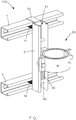
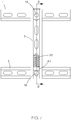
- FIG. 1 illustrates an exemplary cable management system 100 that includes a cable clamp assembly 50 installed onto a slider strut 3, where the slider strut 3 is attached to a first strut 1 and a second strut 2.
- the first strut 1 and/or the second strut 2 may be included in the cable management system 100.
- first strut 1 and/or the second strut 2 may be included as part of an outdoor system (e.g., wind turbine system) onto which the cable management system 100 is attached for managing cables.
- an outdoor system e.g., wind turbine system
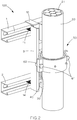
- FIG. 2 shows the cable management system 100 in an assembled state where the cable clamp assembly 50 has been inserted down through the slider channel 31 of the slider strut 3 to rest on top of an elastic element such as the support spring 30.
- the support spring 30 is shown to sit on top of a rigid stop 40 installed within the slider channel 31 of the slider strut 3.
- the cable clamp assembly 50 is shown to be securely holding a cable 20 installed within it.
- the cable 20 may be a cable having an outer insulation jacket layer and one or more conductors 21 (e.g., conductive wires) inside the insulation jacket layer, or other type of cable used to transmit information/data.
- the top of the slider channel 31 may be closed off with a capping member such as, for example, another rigid stop 40 at the top end of the slider channel 31.
- the support spring 30 may be a polymer spring made from an elastic thermoplastic elastomer material. Alternatively, the support spring 30 may be made from a metal material.
- the polymer spring offers advantages such as not suffering from risk of corrosion when installed in the outdoor elements as compared to metal springs.
- the polymer spring may also offer advantages during field installations compared to metal springs such as being safer (lower risk of uncontrolled release) and being easier to install due to its smaller size and lower weight. According to some embodiments where the cable management system 100 is used for substantially horizontal installation scenarios, the support spring 30 may not be included within the slider channel 31.
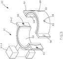
- FIG. 3 shows a partially exploded view of the cable clamp assembly 50.
- the cable clamp assembly 50 includes a lower clamp 51 and an upper clamp 52.
- the lower clamp 51 is comprised of two portions, namely a stem portion 51-1 and a clamp portion 51-2.
- the stem portion 51-1 takes on a substantially cubed shape to fit securely (i.e., snuggly) through the slider channel 31 and travel within the slider channel 31.
- the stem portion 51-1 may travel within the slider channel 31 until it rests on top of the support spring 30 in a vertical installation scenario.
- the clamp portion 51-2 of the lower clamp 51 and the upper clamp 52 are formed into semi-cylindrical shapes to come together around the cable 20.
- the cable clamp assembly 50 may also include a compression grommet sleeve comprise of a first sleeve 53 and a second sleeve 54.
- the first sleeve is placed into the lower clamp 51 and the second sleeve 54 is placed into the upper clamp 52, as shown in FIG 3 .
- the compression grommet may be made from rubber, polymer, sponge, or other elastic material.
- the surface of the compression grommet coming into contact with the clamp portion 51-2 and/or the upper clamp 52 may be shaped (e.g., convex "V" shaped) to abut into an inner surface of the clamp portion 51-2 and/or the upper clamp 52 that is shaped to receive the first sleeve 53 and the second sleeve 54, as described in more detail below.
- shaped e.g., convex "V" shaped
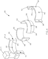
- FIG. 4 shows an exploded view of the cable clamp assembly 50.
- the compression grommet sleeves (first sleeve 53 and second sleeve 54) respectively include both a v-shaped curve 63, 64 and retainment tabs 58 to secure attachment onto the lower clamp 51 and the upper clamp 52, respectively.
- the v-shaped curve 63 on the first sleeve 53 is shaped to fit within a v-groove of the clamp portion 51-2 in the lower clamp 51
- the retainment tabs 58 protruding from the first sleeve 53 are further configured to fit within receiving holes 59 included the clamp portion 51-2 in the lower clamp 51.
- the v-shaped curve 64 on the second sleeve 54 is shaped to fit within a v-groove 66 of the upper clamp 52, and the retainment tabs 58 protruding from the second sleeve 54 are further configured to fit within receiving holes 60 included in the upper clamp 52.
- two retainment tabs 58 are shown to be included on each of the first sleeve 53 and the second sleeve 54, one or more retainment tabs 58 may be included on the first sleeve 53 and/or the second sleeve 54 according to other embodiments, with the lower clamp 51 and the upper clamp 52 adjusting their number of receiving holes 59, 60 accordingly.
- the first sleeve 53 and/or the second sleeve 54 may include no retainment tabs 58. According to still other embodiments, the first sleeve 53 and/or the second sleeve 54 may not include their respective v-shaped curves 63, 64 with the clamp portion 51-2 in the lower clamp 51 and the upper clamp 52 also removing their respective v-grooves 65, 66 accordingly, and instead providing a flat surface.
- the compression grommet is attached to the cable clamp assembly 50.
- Attaching the compression grommet to the cable clamp assembly 50 includes attaching the first sleeve 53 to the clamp portion 51-2 and attaching the second sleeve 54 to the upper clamp 52 using one or more of the attachment mechanisms described herein. Then the lower clamp 51 is lowered into the slider channel 31 in the direction B until the lower clamp 51 rests on top the support spring 30, as shown in FIGs. 5-6 .
- FIG. 6 shows the lower clamp 51 installed into the slider strut 3, and the cable 20 placed between the lower clamp 51 and the upper clamp 52, where the cable 20 is ready to be installed into the cable clamp assembly 50. Then with the cable 20 is placed into the lower clamp 51, the upper clamp 52 (having the second sleeve 54 attached) is brought together with the lower clamp 51 to surround and securely hold the cable 20 between them as shown in FIG. 2 .
- the lower clamp 51 includes threaded holes 55 that are configured to line up with through holes 56 on the upper clamp 52 when the lower clamp 51 and the upper clamp 52 are brought together to achieve the assembled state of the cable clamp assembly 50.
- the fasteners 61 e.g., threaded bolts
- the fasteners 61 are inserted through the open passage provided through the threaded holes 55 and the through holes 56 from the side of the upper clamp 52.
- the fasteners 61 are mated with a termination piece (e.g., nuts) on the side of the lower clamp 51.
- the fasteners 61 are torqued to compress the attached compression grommet sleeve (first sleeve 53 and second sleeve 54) around the cable 20.
- the v-grooves 65, 66 and the v-shaped curves 63, 64 of the compression grommet sleeve work together to resist movement of the cable 20 within the cable clamp assembly 50.
- the fasteners 61 are shown to be hex head bolts, but may also be other types of fastener that can be torqued and be mated by a termination piece on the side of the lower clamp 51.
- the upper clamp 52 may be removed by raising the lower clamp 51 up the slider channel 31 in the direction A, as shown in FIG. 5 .
- FIG. 7 shows a front view of the slider strut 3 being attached to the first strut 1 and the second strut 2.
- FIG. 8 shows a sectional view taken along line 8-8 from FIG. 7 , where the sectional view shown in FIG. 8 illustrates how the slider strut 3 is attached to the first strut 1 by an installation hook 10 and a first strut nut assembly that includes a fastener 13 and a strut nut 12.
- the strut nut 12 includes a strut nut spring 11, although according to other embodiments the strut nut 12 may not include the strut nut spring 11.
- the slider strut 3 is attached to the second strut 2 by a second strut nut assembly that includes a fastener 16 and a strut nut 15.
- the strut nut 15 includes a strut nut spring 14, although according to other embodiments the strut nut 15 may not include the strut nut spring 14.
Landscapes
- Engineering & Computer Science (AREA)
- General Engineering & Computer Science (AREA)
- Mechanical Engineering (AREA)
- Architecture (AREA)
- Civil Engineering (AREA)
- Structural Engineering (AREA)
- Installation Of Indoor Wiring (AREA)
Abstract
Description
- This disclosure relates to a cable management system configured to account for and accommodate physical movement of the cables being managed.
- Cable management, especially in outdoor applications, presents installation complications due to expansion and/or contraction movements in the cables as the cables are exposed to the elements (e.g., temperature fluctuations). In addition to the cable movements caused by exposure to the elements, cables have a tendency to naturally expand in a process referred to as cable creep. Proper cable management systems strive to firmly hold onto cables to prevent cable creep, while also allowing for the movement in the cables from the expansion and/or contraction movements caused by the elements.
- This disclosure relates to a cable management system configured to account for and accommodate physical movement of the cables being managed. The cable management system is configured to provide an elastic element, such as a spring and/or sliding mechanisms, to accommodate for the anticipated expansion and/or contraction movements of the cables being managed. The elastic element is an improvement over strictly rigid members that do not provide any accommodations for movements in the cables being managed. The cable management system may be especially useful for vertical cable installation projects such as those used in wind turbine applications.
- According to an embodiment, a cable management system is disclosed. The cable management system comprising a slider strut comprising a slider channel, and an elastic element installed within the slider channel. The cable management system further comprising a cable clamp comprising a lower clamp installed within the slider channel to rest on the elastic element, an upper clamp, a first compression grommet sleeve attached to the lower clamp, and_a second compression grommet sleeve attached to the upper clamp.
- A detailed description of these and other non-limiting exemplary embodiments of a cable management system, and method of installation, is set forth below together with the accompanying drawings.
-
-
FIG. 1 is a front perspective view of an exemplary cable management system, according to an embodiment. -
FIG. 2 is the front perspective view of the cable management system shown inFIG. 1 , having a cable installed into the cable management system. -
FIG. 3 is a partially exploded view of a cable clamp included in the cable management system shown inFIG. 1 . -
FIG. 4 is an exploded view of the cable clamp included in the cable management system shown inFIG. 1 . -
FIG. 5 is a partially exploded view of the cable management system shown inFIG. 1 , where the cable clamp is outside a slider channel. -
FIG. 6 is a partially exploded view of the cable management system shown inFIG. 1 , where the cable clamp is installed into the slider channel and is ready to receive the cable. -
FIG. 7 is a front facing view of a strut assembly included in the cable management system shown inFIG. 1 . -
FIG. 8 is a sectional view of the strut assembly taken along line 8-8 fromFIG. 7 . - Detailed non-limiting embodiments are disclosed herein. However, it is to be understood that the disclosed embodiments are merely exemplary and may take various and alternative forms. The figures are not necessarily to scale, and features may be exaggerated or minimized to show details of particular components. Therefore, specific structural and functional details disclosed herein may not be limiting, and are provided as a representative basis for teaching one skilled in the art.
- This disclosure relates to a cable management system configured to account for and accommodate physical movement of the cables it manages. The cable management system is configured to provide an elastic element, such as a spring and/or sliding mechanism, to accommodate for the anticipated expansion and/or contraction movements of the cables being managed. The elastic element is an improvement over strictly rigid members that do not provide any accommodations for movements in the cables being managed. The cable management system may be especially useful for vertical cable installation projects such as those used in wind turbine applications, and/or horizontal cable installation project taking place outdoors where the elements may be a factor in moving the cables.
-
FIG. 1 illustrates an exemplarycable management system 100 that includes acable clamp assembly 50 installed onto aslider strut 3, where theslider strut 3 is attached to afirst strut 1 and asecond strut 2. Thefirst strut 1 and/or thesecond strut 2 may be included in thecable management system 100. Alternatively,first strut 1 and/or thesecond strut 2 may be included as part of an outdoor system (e.g., wind turbine system) onto which thecable management system 100 is attached for managing cables. -
FIG. 2 shows thecable management system 100 in an assembled state where thecable clamp assembly 50 has been inserted down through theslider channel 31 of theslider strut 3 to rest on top of an elastic element such as thesupport spring 30. Thesupport spring 30 is shown to sit on top of arigid stop 40 installed within theslider channel 31 of theslider strut 3. In this assembled state shown inFIG. 2 , thecable clamp assembly 50 is shown to be securely holding acable 20 installed within it. Thecable 20 may be a cable having an outer insulation jacket layer and one or more conductors 21 (e.g., conductive wires) inside the insulation jacket layer, or other type of cable used to transmit information/data. Although not expressly illustrated, the top of theslider channel 31 may be closed off with a capping member such as, for example, anotherrigid stop 40 at the top end of theslider channel 31. - The
support spring 30 may be a polymer spring made from an elastic thermoplastic elastomer material. Alternatively, thesupport spring 30 may be made from a metal material. The polymer spring offers advantages such as not suffering from risk of corrosion when installed in the outdoor elements as compared to metal springs. The polymer spring may also offer advantages during field installations compared to metal springs such as being safer (lower risk of uncontrolled release) and being easier to install due to its smaller size and lower weight. According to some embodiments where thecable management system 100 is used for substantially horizontal installation scenarios, thesupport spring 30 may not be included within theslider channel 31. -
FIG. 3 shows a partially exploded view of thecable clamp assembly 50. Thecable clamp assembly 50 includes alower clamp 51 and anupper clamp 52. Thelower clamp 51 is comprised of two portions, namely a stem portion 51-1 and a clamp portion 51-2. The stem portion 51-1 takes on a substantially cubed shape to fit securely (i.e., snuggly) through theslider channel 31 and travel within theslider channel 31. The stem portion 51-1 may travel within theslider channel 31 until it rests on top of thesupport spring 30 in a vertical installation scenario. The clamp portion 51-2 of thelower clamp 51 and theupper clamp 52 are formed into semi-cylindrical shapes to come together around thecable 20. To provide a more secure fit with thecable 20, thecable clamp assembly 50 may also include a compression grommet sleeve comprise of afirst sleeve 53 and asecond sleeve 54. The first sleeve is placed into thelower clamp 51 and thesecond sleeve 54 is placed into theupper clamp 52, as shown inFIG 3 . The compression grommet may be made from rubber, polymer, sponge, or other elastic material. The surface of the compression grommet coming into contact with the clamp portion 51-2 and/or theupper clamp 52, may be shaped (e.g., convex "V" shaped) to abut into an inner surface of the clamp portion 51-2 and/or theupper clamp 52 that is shaped to receive thefirst sleeve 53 and thesecond sleeve 54, as described in more detail below. -
FIG. 4 shows an exploded view of thecable clamp assembly 50. The compression grommet sleeves (first sleeve 53 and second sleeve 54) respectively include both a v-shaped curve retainment tabs 58 to secure attachment onto thelower clamp 51 and theupper clamp 52, respectively. For example, the v-shaped curve 63 on thefirst sleeve 53 is shaped to fit within a v-groove of the clamp portion 51-2 in thelower clamp 51, and theretainment tabs 58 protruding from thefirst sleeve 53 are further configured to fit within receivingholes 59 included the clamp portion 51-2 in thelower clamp 51. Similarly, the v-shaped curve 64 on thesecond sleeve 54 is shaped to fit within a v-groove 66 of theupper clamp 52, and theretainment tabs 58 protruding from thesecond sleeve 54 are further configured to fit within receivingholes 60 included in theupper clamp 52. Although tworetainment tabs 58 are shown to be included on each of thefirst sleeve 53 and thesecond sleeve 54, one ormore retainment tabs 58 may be included on thefirst sleeve 53 and/or thesecond sleeve 54 according to other embodiments, with thelower clamp 51 and theupper clamp 52 adjusting their number of receivingholes first sleeve 53 and/or thesecond sleeve 54 may include noretainment tabs 58. According to still other embodiments, thefirst sleeve 53 and/or thesecond sleeve 54 may not include their respective v-shaped curves lower clamp 51 and theupper clamp 52 also removing their respective v-grooves - To initiate an installation of a cable onto the
cable management system 100, the compression grommet is attached to thecable clamp assembly 50. Attaching the compression grommet to thecable clamp assembly 50 includes attaching thefirst sleeve 53 to the clamp portion 51-2 and attaching thesecond sleeve 54 to theupper clamp 52 using one or more of the attachment mechanisms described herein. Then thelower clamp 51 is lowered into theslider channel 31 in the direction B until thelower clamp 51 rests on top thesupport spring 30, as shown inFIGs. 5-6 . - To continue the installation, the
cable 20 is placed into thelower clamp 51 by abutting thecable 20 against thefirst sleeve 53.FIG. 6 shows thelower clamp 51 installed into theslider strut 3, and thecable 20 placed between thelower clamp 51 and theupper clamp 52, where thecable 20 is ready to be installed into thecable clamp assembly 50. Then with thecable 20 is placed into thelower clamp 51, the upper clamp 52 (having thesecond sleeve 54 attached) is brought together with thelower clamp 51 to surround and securely hold thecable 20 between them as shown inFIG. 2 . - As shown in
FIG. 4 , thelower clamp 51 includes threadedholes 55 that are configured to line up with throughholes 56 on theupper clamp 52 when thelower clamp 51 and theupper clamp 52 are brought together to achieve the assembled state of thecable clamp assembly 50. So as part of a final step in the installation process, as the threadedhole 55 and the throughholes 56 line up with each other to present an open passage, the fasteners 61 (e.g., threaded bolts) are inserted through the open passage provided through the threadedholes 55 and the throughholes 56 from the side of theupper clamp 52. Then thefasteners 61 are mated with a termination piece (e.g., nuts) on the side of thelower clamp 51. Thefasteners 61 are torqued to compress the attached compression grommet sleeve (first sleeve 53 and second sleeve 54) around thecable 20. The v-grooves curves cable 20 within thecable clamp assembly 50. Thefasteners 61 are shown to be hex head bolts, but may also be other types of fastener that can be torqued and be mated by a termination piece on the side of thelower clamp 51. - After installation, the
upper clamp 52 may be removed by raising thelower clamp 51 up theslider channel 31 in the direction A, as shown inFIG. 5 . -
FIG. 7 shows a front view of theslider strut 3 being attached to thefirst strut 1 and thesecond strut 2.FIG. 8 shows a sectional view taken along line 8-8 fromFIG. 7 , where the sectional view shown inFIG. 8 illustrates how theslider strut 3 is attached to thefirst strut 1 by aninstallation hook 10 and a first strut nut assembly that includes afastener 13 and astrut nut 12. According to the embodiments disclosed byFIG. 8 , thestrut nut 12 includes astrut nut spring 11, although according to other embodiments thestrut nut 12 may not include thestrut nut spring 11. On the other end, theslider strut 3 is attached to thesecond strut 2 by a second strut nut assembly that includes afastener 16 and astrut nut 15. According to the embodiments disclosed byFIG. 8 , thestrut nut 15 includes astrut nut spring 14, although according to other embodiments thestrut nut 15 may not include thestrut nut spring 14. - Furthermore, while the particular embodiments described herein have been shown and described, it will be obvious to those skilled in the art that changes and modifications may be made without departing from the teaching of the invention. The matter set forth in the foregoing description and accompanying drawings is offered by way of illustration only and not as limitation. The actual scope of the invention is intended to be defined in the following claims when viewed in their proper perspective.
- Also disclosed herein are the following numbered clauses:
- 1. A cable management system comprising:
- a slider strut comprising:
- a slider channel; and
- an elastic element installed within the slider channel; and
- a cable clamp comprising:
- a lower clamp installed within the slider channel and configured to translate within the slider channel; and
- an upper clamp configured to attach to the lower clamp via at least one fastener.
- a slider strut comprising:
- 2. The cable management system of
clause 1, the cable clamp further comprising:- a first compression grommet sleeve configured to attach to the lower clamp; and
- a second compression grommet sleeve configured to attach to the upper clamp.
- 3. The cable management system of
clause 1, wherein the lower clamp comprises:- a stem portion configured to fit and translate within the slider channel; and
- a clamp portion.
- 4. The cable management system of
clause 1, the cable clamp further comprising:- a first compression grommet sleeve configured to attach to the lower clamp; and
- a second compression grommet sleeve configured to attach to the upper clamp;
- wherein the lower clamp includes a first v-groove and the first compression grommet sleeve includes a first v-shaped curve configured to fit into the first v-groove of the lower clamp; and
- wherein the upper clamp includes a second v-groove and the second compression grommet sleeve includes a second v-shaped curve configured to fit into the second v-groove of the upper clamp.
- 5. The cable management system of
clause 1, the cable clamp further comprising:- a first compression grommet sleeve configured to attach to the lower clamp; and
- a second compression grommet sleeve configured to attach to the upper clamp;
- wherein the first compression grommet sleeve includes a first retainment protrusion, and the lower clamp includes a first receiving hole for receiving the first retainment protrusion; and
- wherein the second compression grommet sleeve includes a second retainment protrusion, and the upper clamp includes a second receiving hole for receiving the second retainment protrusion.
- 6. The cable management system of
clause 1, wherein the elastic element is a polymer spring. - 7. The cable management system of
clause 1, wherein the elastic element is located at a bottom end of the slider channel. - 8. The cable management system of
clause 1, further comprising an attachment assembly configured to attach the cable management system to a device strut. - 9. The cable management system of
clause 8, wherein the attachment assembly comprises an installation hook, a fastener, a strut nut, and a strut nut spring. - 10. The cable management system of
clause 1, further comprising a rigid stop attached within the slider channel, wherein the elastic element rests on top of the rigid stop. - 11. A cable management system comprising:
- a slider strut comprising:
- a slider channel; and
- stopping member positioned within the slider channel; and
- a cable clamp comprising:
- a lower clamp installed within the slider channel and configured to translate within the slider channel; and
- an upper clamp configured to attach to the lower clamp via at least one fastener.
- a slider strut comprising:
- 12. The cable management system of
clause 11, the cable clamp further comprising:- a first compression grommet sleeve configured to attach to the lower clamp; and
- a second compression grommet sleeve configured to attach to the upper clamp.
- 13. The cable management system of
clause 11, wherein the lower clamp comprises:- a stem portion configured to fit and translate within the slider channel; and
- a clamp portion.
- 14. The cable management system of
clause 11, the cable clamp further comprising:- a first compression grommet sleeve configured to attach to the lower clamp; and
- a second compression grommet sleeve configured to attach to the upper clamp;
- wherein the lower clamp includes a first v-groove and the first compression grommet sleeve includes a first v-shaped curve configured to fit into the first v-groove of the lower clamp; and
- wherein the upper clamp includes a second v-groove and the second compression grommet sleeve includes a second v-shaped curve configured to fit into the second v-groove of the upper clamp.
- 15. The cable management system of
clause 11, the cable clamp further comprising:- a first compression grommet sleeve configured to attach to the lower clamp; and
- a second compression grommet sleeve configured to attach to the upper clamp;
- wherein the first compression grommet sleeve includes a first retainment protrusion, and the lower clamp includes a first receiving hole for receiving the first retainment protrusion; and
- wherein the second compression grommet sleeve includes a second retainment protrusion, and the upper clamp includes a second receiving hole for receiving the second retainment protrusion.
- 16. The cable management system of
clause 11, wherein the stopping member is located at a top end of the slider channel. - 17. The cable management system of
clause 11, wherein the stopping member is located at a bottom end of the slider channel. - 18. The cable management system of
clause 11, further comprising an attachment assembly configured to attach the cable management system to a device strut. - 19. The cable management system of clause 18, wherein the attachment assembly comprises an installation hook, a fastener, a strut nut, and a strut nut spring.
- 20. The cable management system of
clause 11, further comprising a capping member at a top end of the sliding channel.
Claims (15)
- A cable management system comprising:a slider strut comprising:a slider channel; andan elastic element installed within the slider channel; anda cable clamp comprising:a lower clamp installed within the slider channel and configured to translate within the slider channel; andan upper clamp configured to attach to the lower clamp via at least one fastener.
- The cable management system of claim 1, the cable clamp further comprising:a first compression grommet sleeve configured to attach to the lower clamp; anda second compression grommet sleeve configured to attach to the upper clamp.
- The cable management system of claim 1, wherein the lower clamp comprises:a stem portion configured to fit and translate within the slider channel; anda clamp portion.
- The cable management system of claim 1, the cable clamp further comprising:a first compression grommet sleeve configured to attach to the lower clamp; anda second compression grommet sleeve configured to attach to the upper clamp;wherein the lower clamp includes a first v-groove and the first compression grommet sleeve includes a first v-shaped curve configured to fit into the first v-groove of the lower clamp; andwherein the upper clamp includes a second v-groove and the second compression grommet sleeve includes a second v-shaped curve configured to fit into the second v-groove of the upper clamp.
- The cable management system of claim 1, the cable clamp further comprising:a first compression grommet sleeve configured to attach to the lower clamp; anda second compression grommet sleeve configured to attach to the upper clamp;wherein the first compression grommet sleeve includes a first retainment protrusion, and the lower clamp includes a first receiving hole for receiving the first retainment protrusion; andwherein the second compression grommet sleeve includes a second retainment protrusion, and the upper clamp includes a second receiving hole for receiving the second retainment protrusion.
- The cable management system of claim 1, wherein the elastic element is a polymer spring; or / and optionally
wherein the elastic element is located at a bottom end of the slider channel. - The cable management system of claim 1, further comprising an attachment assembly configured to attach the cable management system to a device strut; and optionally
wherein the attachment assembly comprises an installation hook, a fastener, a strut nut, and a strut nut spring. - The cable management system of claim 1, further comprising a rigid stop attached within the slider channel, wherein the elastic element rests on top of the rigid stop.
- A cable management system comprising:a slider strut comprising:a slider channel; andstopping member positioned within the slider channel; anda cable clamp comprising:a lower clamp installed within the slider channel and configured to translate within the slider channel; andan upper clamp configured to attach to the lower clamp via at least one fastener.
- The cable management system of claim 9, the cable clamp further comprising:a first compression grommet sleeve configured to attach to the lower clamp; anda second compression grommet sleeve configured to attach to the upper clamp; or / and optionallywherein the lower clamp comprises:a stem portion configured to fit and translate within the slider channel; anda clamp portion.
- The cable management system of claim 9, the cable clamp further comprising:a first compression grommet sleeve configured to attach to the lower clamp; anda second compression grommet sleeve configured to attach to the upper clamp;wherein the lower clamp includes a first v-groove and the first compression grommet sleeve includes a first v-shaped curve configured to fit into the first v-groove of the lower clamp; andwherein the upper clamp includes a second v-groove and the second compression grommet sleeve includes a second v-shaped curve configured to fit into the second v-groove of the upper clamp.
- The cable management system of claim 9, the cable clamp further comprising:a first compression grommet sleeve configured to attach to the lower clamp; anda second compression grommet sleeve configured to attach to the upper clamp;wherein the first compression grommet sleeve includes a first retainment protrusion, and the lower clamp includes a first receiving hole for receiving the first retainment protrusion; andwherein the second compression grommet sleeve includes a second retainment protrusion, and the upper clamp includes a second receiving hole for receiving the second retainment protrusion.
- The cable management system of claim 9, wherein the stopping member is located at a top end of the slider channel; or
wherein the stopping member is located at a bottom end of the slider channel. - The cable management system of claim 9, further comprising an attachment assembly configured to attach the cable management system to a device strut; and optionally
wherein the attachment assembly comprises an installation hook, a fastener, a strut nut, and a strut nut spring. - The cable management system of claim 9, further comprising a capping member at a top end of the sliding channel.
Applications Claiming Priority (2)
| Application Number | Priority Date | Filing Date | Title |
|---|---|---|---|
| US202063045239P | 2020-06-29 | 2020-06-29 | |
| US17/304,220 US11651869B2 (en) | 2020-06-29 | 2021-06-16 | Thermal expansion slide with cable clamp |
Publications (1)
| Publication Number | Publication Date |
|---|---|
| EP3934038A1 true EP3934038A1 (en) | 2022-01-05 |
Family
ID=76708103
Family Applications (1)
| Application Number | Title | Priority Date | Filing Date |
|---|---|---|---|
| EP21182500.5A Pending EP3934038A1 (en) | 2020-06-29 | 2021-06-29 | Thermal expansion slide with cable clamp |
Country Status (4)
| Country | Link |
|---|---|
| US (1) | US11651869B2 (en) |
| EP (1) | EP3934038A1 (en) |
| KR (1) | KR102799487B1 (en) |
| CN (1) | CN216146031U (en) |
Families Citing this family (14)
| Publication number | Priority date | Publication date | Assignee | Title |
|---|---|---|---|---|
| US11835165B2 (en) * | 2020-12-28 | 2023-12-05 | Sti Co., Ltd. | Male connector holder for automatic chemical supply apparatus |
| KR102516372B1 (en) * | 2021-01-20 | 2023-03-31 | (주)에스티아이 | Male connector holding unit of chemical automatic supply apparatus |
| US12129946B2 (en) * | 2021-07-12 | 2024-10-29 | Dustin Zander | Protective bracket for loader hose lines |
| EP4119793B1 (en) * | 2021-07-15 | 2026-01-21 | General Electric Renovables España S.L. | Cable guiding structure for a tower for a wind turbine, method for mounting a cable guiding structure, and wind turbine |
| JP7700652B2 (en) * | 2021-11-26 | 2025-07-01 | 住友電装株式会社 | Wire Harness |
| USD991773S1 (en) * | 2021-12-03 | 2023-07-11 | Hailin Liu | Fixed holder |
| CN114430154B (en) * | 2022-02-17 | 2023-10-31 | 北京大敖海洋科技有限公司 | Anti-bending clamping device for deep sea cable and adjusting method |
| CN115425585B (en) * | 2022-09-05 | 2025-05-02 | 浙江博莱特制冷设备有限公司 | A mounting structure for a motor power supply cable |
| CN116111535B (en) * | 2023-04-17 | 2023-07-28 | 国网山东省电力公司潍坊市寒亭区供电公司 | Cable clamp for cable installation |
| US12341329B2 (en) * | 2023-04-17 | 2025-06-24 | Bruce Brown | Wire management device |
| US12494625B2 (en) | 2023-12-18 | 2025-12-09 | Cablofil, Inc. | Cable bus management block |
| CN118431988B (en) * | 2024-04-07 | 2025-08-01 | 中山市昭远电器有限公司 | Flexible fixing device for cable installation and erection |
| CN118728669B (en) * | 2024-06-03 | 2025-10-17 | 国电联合动力技术有限公司 | Cable limiting device, control method and wind turbine generator |
| CN118487193B (en) * | 2024-07-16 | 2024-10-18 | 国网山东省电力公司滨州市滨城区供电公司 | A buffer clamp mechanism for cable support |
Citations (7)
| Publication number | Priority date | Publication date | Assignee | Title |
|---|---|---|---|---|
| US2355742A (en) * | 1942-09-21 | 1944-08-15 | Adel Prec Products Corp | Conduit supporting block |
| EP1957844A1 (en) * | 2005-12-06 | 2008-08-20 | HYDAC Accessories GmbH | Insert element for pipe clamps, and pipe clamp for accommodating such an insert element |
| KR20090063740A (en) * | 2007-12-14 | 2009-06-18 | 현대자동차주식회사 | Circuit absorption device of wiring |
| WO2011025081A1 (en) * | 2009-08-24 | 2011-03-03 | Choi Kwang-Sul | Cable guide system of industrial robot |
| DE102014200870A1 (en) * | 2013-01-18 | 2014-07-24 | Leoni Kabel Holding Gmbh | Device for guiding and resetting flexible line of articulated arm robot, particularly for guiding hose pack, has resetting mechanism which has segments, namely base segment for fastening at articulated arm robot and pull-out segment |
| FR3001175A1 (en) * | 2013-01-18 | 2014-07-25 | Leoni Cia Cable Systems | Device for guiding and recalling flexible pipe of e.g. industrial robot, has elastic return mechanism to return slide towards position and comprising pulley connected to spiral spring to actuate spring and traction cable fixed at pulley |
| US20150083463A1 (en) * | 2012-04-16 | 2015-03-26 | Tappat Engineering Pty Ltd | Cable clamp |
Family Cites Families (26)
| Publication number | Priority date | Publication date | Assignee | Title |
|---|---|---|---|---|
| US2696139A (en) | 1952-05-28 | 1954-12-07 | Charles W Attwood | Nut for locking engagement with unistrut |
| US3683450A (en) | 1970-06-22 | 1972-08-15 | Rixson Inc | Friction door holder |
| US4073114A (en) | 1977-04-01 | 1978-02-14 | Unistrut Corporation | Insert assembly for use in pre-stressed concrete structures |
| US4595165A (en) * | 1984-12-24 | 1986-06-17 | Aluminum Company Of America | Adjustable anchoring assembly |
| US4662590A (en) * | 1986-05-05 | 1987-05-05 | Hungerford Charles S Jr | Connector device for supporting a conduct in a flanged channel |
| NZ241458A (en) * | 1991-02-05 | 1994-12-22 | Cateye Co Ltd | Interlocking rail and groove fastening for bicycle fittings such as light: transversely latching mechanism |
| US5261633A (en) * | 1992-12-17 | 1993-11-16 | Mastro Ronald J | Pipe support system |
| KR100754806B1 (en) | 2004-11-09 | 2007-09-03 | 정근우 | Hydraulically Operated Wash Basin Height Adjuster |
| US7614593B2 (en) | 2007-05-17 | 2009-11-10 | International Clamps, Inc. | Lined clamp for hoses and control lines |
| US7770848B2 (en) * | 2007-11-29 | 2010-08-10 | The Boeing Company | Clamp for securing an object to a structure |
| KR20090063474A (en) | 2007-12-14 | 2009-06-18 | 현대자동차주식회사 | Check valve |
| US8998150B2 (en) | 2010-01-29 | 2015-04-07 | The Subsea Company | Retrofit clamp for MUX, umbilicals and IWOCS |
| GB2478959B (en) | 2010-03-24 | 2014-11-26 | Graphicshow Cable Accessories Gca Ltd | Clamp |
| KR101277856B1 (en) | 2010-03-31 | 2013-06-27 | 미츠비시 쥬고교 가부시키가이샤 | Wind turbine generator |
| EP2518844B1 (en) | 2011-04-27 | 2013-11-13 | Siemens Aktiengesellschaft | Arrangement and method for installing cables |
| GB201214892D0 (en) | 2012-08-21 | 2012-10-03 | Ellis Patents Ltd | Modular cable hanger systems |
| US9341206B2 (en) * | 2013-03-15 | 2016-05-17 | Panduit Corp. | Flange for support channel assembly |
| DE102013010821A1 (en) | 2013-06-28 | 2014-12-31 | Hydac Accessories Gmbh | Device for fixing and / or guiding strand-like elements |
| EP2918828B1 (en) | 2014-03-11 | 2023-07-26 | Siemens Gamesa Renewable Energy A/S | Cable support arrangement |
| US20150276092A1 (en) | 2014-03-27 | 2015-10-01 | Unistrut International Corporation | Enhanced corrosion resistant channels, fittings and fasteners |
| WO2016049941A1 (en) | 2014-10-03 | 2016-04-07 | General Electric Company | Spacer for wind turbine cables |
| DE102014016869A1 (en) | 2014-11-14 | 2016-05-19 | Hydac Accessories Gmbh | Device for fixing and / or guiding strand-like elements |
| DE102015013791A1 (en) | 2015-10-22 | 2017-04-27 | Hydac Accessories Gmbh | Device for fixing and / or guiding strand-like elements |
| US10266122B2 (en) | 2016-01-13 | 2019-04-23 | Panduit Corp. | Ladder rack and cable cleat system |
| US10302249B1 (en) | 2016-07-08 | 2019-05-28 | Voytas Inc. | Speed strut clamp |
| US10221994B2 (en) * | 2016-07-19 | 2019-03-05 | Steven Marc Baiera | Modular mounting system |
-
2021
- 2021-06-16 US US17/304,220 patent/US11651869B2/en active Active
- 2021-06-22 KR KR1020210080546A patent/KR102799487B1/en active Active
- 2021-06-28 CN CN202121447946.4U patent/CN216146031U/en active Active
- 2021-06-29 EP EP21182500.5A patent/EP3934038A1/en active Pending
Patent Citations (7)
| Publication number | Priority date | Publication date | Assignee | Title |
|---|---|---|---|---|
| US2355742A (en) * | 1942-09-21 | 1944-08-15 | Adel Prec Products Corp | Conduit supporting block |
| EP1957844A1 (en) * | 2005-12-06 | 2008-08-20 | HYDAC Accessories GmbH | Insert element for pipe clamps, and pipe clamp for accommodating such an insert element |
| KR20090063740A (en) * | 2007-12-14 | 2009-06-18 | 현대자동차주식회사 | Circuit absorption device of wiring |
| WO2011025081A1 (en) * | 2009-08-24 | 2011-03-03 | Choi Kwang-Sul | Cable guide system of industrial robot |
| US20150083463A1 (en) * | 2012-04-16 | 2015-03-26 | Tappat Engineering Pty Ltd | Cable clamp |
| DE102014200870A1 (en) * | 2013-01-18 | 2014-07-24 | Leoni Kabel Holding Gmbh | Device for guiding and resetting flexible line of articulated arm robot, particularly for guiding hose pack, has resetting mechanism which has segments, namely base segment for fastening at articulated arm robot and pull-out segment |
| FR3001175A1 (en) * | 2013-01-18 | 2014-07-25 | Leoni Cia Cable Systems | Device for guiding and recalling flexible pipe of e.g. industrial robot, has elastic return mechanism to return slide towards position and comprising pulley connected to spiral spring to actuate spring and traction cable fixed at pulley |
Non-Patent Citations (1)
| Title |
|---|
| THORNE & DERRICK: "Ellis Patents No Bolts Cleat - Polymeric Cable Cleats for Rail Cables", 7 March 2019 (2019-03-07), XP055859526, Retrieved from the Internet <URL:https://www.youtube.com/watch?v=ZFCTEIzYkvk&t=93s> [retrieved on 20211109] * |
Also Published As
| Publication number | Publication date |
|---|---|
| KR102799487B1 (en) | 2025-04-23 |
| US11651869B2 (en) | 2023-05-16 |
| US20210407703A1 (en) | 2021-12-30 |
| KR20220001473A (en) | 2022-01-05 |
| CN216146031U (en) | 2022-03-29 |
Similar Documents
| Publication | Publication Date | Title |
|---|---|---|
| US11651869B2 (en) | Thermal expansion slide with cable clamp | |
| EP2595246B1 (en) | Cable clamp having winged flanges | |
| KR101785014B1 (en) | Coupling cable with improved fixing power cable | |
| JP2013524044A (en) | Solar cell assembly secured on a sloping roof with minimal penetration and associated method | |
| US20170346439A1 (en) | Apparatus for Mounting Conduit to Solar Panel Arrays | |
| CN103003081B (en) | Device for positional adjustment and attachment of a locking member on a support by compensating for play | |
| CN105830338A (en) | Housing for solar panel electric connection | |
| US12535169B2 (en) | Pipeline mounting head for vehicle, pipeline structure and vehicle | |
| KR101822905B1 (en) | Seismic isolation device for a bridge | |
| CN201891938U (en) | Clamp assembly for securing cables to structural supports and wind turbine | |
| AU2013405481B2 (en) | Bend stiffener | |
| CN119891065A (en) | Connection structure of conductor spacer and wire | |
| CN219202018U (en) | Optical cable hanger device for 5G base station construction | |
| CN111396637A (en) | Water supply and drainage pipe connecting and fixing support for building construction and installation engineering | |
| CN114977052B (en) | Wireless charging system installation device | |
| US4483500A (en) | Piping support system for liquid-metal fast-breeder reactor | |
| KR102076801B1 (en) | Extra-high voltage distribution line with adjustable vertical position | |
| CN217482163U (en) | Antidetonation support with freely angle regulation | |
| CN221236501U (en) | Cross arm annular hoop | |
| CN115313535B (en) | Mounting structure | |
| CN224264621U (en) | A cable tray connection structure | |
| CN219571112U (en) | Hydropower pipeline fixing frame | |
| CN223638932U (en) | A trough-type cable tray that is easy to assemble | |
| CN216819283U (en) | Device for fixing cable and vertical bridge structure comprising same | |
| CN219760895U (en) | Cable beam connection node for light Fu Rouxing bracket |
Legal Events
| Date | Code | Title | Description |
|---|---|---|---|
| PUAI | Public reference made under article 153(3) epc to a published international application that has entered the european phase |
Free format text: ORIGINAL CODE: 0009012 |
|
| STAA | Information on the status of an ep patent application or granted ep patent |
Free format text: STATUS: THE APPLICATION HAS BEEN PUBLISHED |
|
| AK | Designated contracting states |
Kind code of ref document: A1 Designated state(s): AL AT BE BG CH CY CZ DE DK EE ES FI FR GB GR HR HU IE IS IT LI LT LU LV MC MK MT NL NO PL PT RO RS SE SI SK SM TR |
|
| B565 | Issuance of search results under rule 164(2) epc |
Effective date: 20211118 |
|
| STAA | Information on the status of an ep patent application or granted ep patent |
Free format text: STATUS: REQUEST FOR EXAMINATION WAS MADE |
|
| 17P | Request for examination filed |
Effective date: 20220705 |
|
| RBV | Designated contracting states (corrected) |
Designated state(s): AL AT BE BG CH CY CZ DE DK EE ES FI FR GB GR HR HU IE IS IT LI LT LU LV MC MK MT NL NO PL PT RO RS SE SI SK SM TR |
|
| STAA | Information on the status of an ep patent application or granted ep patent |
Free format text: STATUS: EXAMINATION IS IN PROGRESS |
|
| 17Q | First examination report despatched |
Effective date: 20240312 |