EP3933943A1 - Light emitting device - Google Patents
Light emitting device Download PDFInfo
- Publication number
- EP3933943A1 EP3933943A1 EP21182546.8A EP21182546A EP3933943A1 EP 3933943 A1 EP3933943 A1 EP 3933943A1 EP 21182546 A EP21182546 A EP 21182546A EP 3933943 A1 EP3933943 A1 EP 3933943A1
- Authority
- EP
- European Patent Office
- Prior art keywords
- light
- light emitting
- rendering index
- emitting device
- color rendering
- Prior art date
- Legal status (The legal status is an assumption and is not a legal conclusion. Google has not performed a legal analysis and makes no representation as to the accuracy of the status listed.)
- Granted
Links
Images






Classifications
-
- F—MECHANICAL ENGINEERING; LIGHTING; HEATING; WEAPONS; BLASTING
- F21—LIGHTING
- F21V—FUNCTIONAL FEATURES OR DETAILS OF LIGHTING DEVICES OR SYSTEMS THEREOF; STRUCTURAL COMBINATIONS OF LIGHTING DEVICES WITH OTHER ARTICLES, NOT OTHERWISE PROVIDED FOR
- F21V9/00—Elements for modifying spectral properties, polarisation or intensity of the light emitted, e.g. filters
- F21V9/40—Elements for modifying spectral properties, polarisation or intensity of the light emitted, e.g. filters with provision for controlling spectral properties, e.g. colour, or intensity
- F21V9/45—Elements for modifying spectral properties, polarisation or intensity of the light emitted, e.g. filters with provision for controlling spectral properties, e.g. colour, or intensity by adjustment of photoluminescent elements
-
- H—ELECTRICITY
- H10—SEMICONDUCTOR DEVICES; ELECTRIC SOLID-STATE DEVICES NOT OTHERWISE PROVIDED FOR
- H10W—GENERIC PACKAGES, INTERCONNECTIONS, CONNECTORS OR OTHER CONSTRUCTIONAL DETAILS OF DEVICES COVERED BY CLASS H10
- H10W90/00—Package configurations
-
- H—ELECTRICITY
- H05—ELECTRIC TECHNIQUES NOT OTHERWISE PROVIDED FOR
- H05B—ELECTRIC HEATING; ELECTRIC LIGHT SOURCES NOT OTHERWISE PROVIDED FOR; CIRCUIT ARRANGEMENTS FOR ELECTRIC LIGHT SOURCES, IN GENERAL
- H05B45/00—Circuit arrangements for operating light-emitting diodes [LED]
- H05B45/20—Controlling the colour of the light
-
- H—ELECTRICITY
- H10—SEMICONDUCTOR DEVICES; ELECTRIC SOLID-STATE DEVICES NOT OTHERWISE PROVIDED FOR
- H10H—INORGANIC LIGHT-EMITTING SEMICONDUCTOR DEVICES HAVING POTENTIAL BARRIERS
- H10H20/00—Individual inorganic light-emitting semiconductor devices having potential barriers, e.g. light-emitting diodes [LED]
- H10H20/80—Constructional details
- H10H20/85—Packages
- H10H20/851—Wavelength conversion means
- H10H20/8511—Wavelength conversion means characterised by their material, e.g. binder
- H10H20/8512—Wavelength conversion materials
-
- H—ELECTRICITY
- H10—SEMICONDUCTOR DEVICES; ELECTRIC SOLID-STATE DEVICES NOT OTHERWISE PROVIDED FOR
- H10H—INORGANIC LIGHT-EMITTING SEMICONDUCTOR DEVICES HAVING POTENTIAL BARRIERS
- H10H20/00—Individual inorganic light-emitting semiconductor devices having potential barriers, e.g. light-emitting diodes [LED]
- H10H20/80—Constructional details
- H10H20/85—Packages
- H10H20/851—Wavelength conversion means
- H10H20/8511—Wavelength conversion means characterised by their material, e.g. binder
- H10H20/8512—Wavelength conversion materials
- H10H20/8513—Wavelength conversion materials having two or more wavelength conversion materials
-
- Y—GENERAL TAGGING OF NEW TECHNOLOGICAL DEVELOPMENTS; GENERAL TAGGING OF CROSS-SECTIONAL TECHNOLOGIES SPANNING OVER SEVERAL SECTIONS OF THE IPC; TECHNICAL SUBJECTS COVERED BY FORMER USPC CROSS-REFERENCE ART COLLECTIONS [XRACs] AND DIGESTS
- Y02—TECHNOLOGIES OR APPLICATIONS FOR MITIGATION OR ADAPTATION AGAINST CLIMATE CHANGE
- Y02B—CLIMATE CHANGE MITIGATION TECHNOLOGIES RELATED TO BUILDINGS, e.g. HOUSING, HOUSE APPLIANCES OR RELATED END-USER APPLICATIONS
- Y02B20/00—Energy efficient lighting technologies, e.g. halogen lamps or gas discharge lamps
- Y02B20/40—Control techniques providing energy savings, e.g. smart controller or presence detection
Definitions
- the present disclosure relates to a light emitting device.
- Light such as illumination and displays
- WELL certification Well Building Standard
- IWBI International WELL Building Institute
- WELL certification evaluates buildings such as offices on multiple items, such as air, water, food, light, and comfort, and gives certification if they meet the criteria.
- Examples of the verification item of light in WELL certification include consideration for the visual environment, consideration for circadian, consideration for glare from fixtures and sunlight, and color rendering properties.
- the present disclosure has an object to provide a light emitting device in consideration of circadian rhythm and color rendering properties.
- the light emitting device disclosed in the embodiment comprises one or a plurality of light emitting elements and a plurality of fluorescent materials, and emits a first light from one or a plurality of light emitting elements and one or a plurality of first fluorescent materials among the one or a plurality of light emitting elements and the plurality of fluorescent materials, a second light from one or a plurality of light emitting elements and one or a plurality of second fluorescent materials containing at least a fluorescent material different from the first fluorescent materials among the one or a plurality of light emitting elements and the plurality of fluorescent materials, and a third light from one or a plurality of light emitting elements and one or a plurality of third fluorescent materials containing at least a fluorescent material different from the first fluorescent materials and the second fluorescent materials among the one or a plurality of light emitting elements and the plurality of fluorescent materials, wherein the first light has a first color temperature with a correlated color temperature in a range of 1,500 K or more and 3,500 K or less, and has a color rendering index R
- a light emitting device in consideration of circadian rhythm and color rendering properties can be provided.
- the WELL certification described in the background requires an illumination design in consideration of circadian.
- consideration of circadian means consideration of circadian rhythm.
- the circadian rhythm of human beings is longer than one day and is approximately 25 hours, and when it is not adjusted to one day, that is, a 24 hours cycle, the rhythm cycle deviates from one day. Light thus plays an important role as a synchronization factor for adjusting to 24 hours.
- the human biological clock is adjusted to 24 hours by being exposed to the sunlight, which naturally causes people to live in the rhythm of one day, such as waking up in the morning and going to sleep at night.
- the human body is equipped with a synchronization function utilizing light in order to live in a 24-hour rhythm.
- a synchronization function utilizing light in order to live in a 24-hour rhythm.
- the suprachiasmatic nucleus which plays the role of the biological clock that controls circadian rhythm.
- ipRGC intrinsically photosensitive retinal ganglion cell
- the ipRGC contains a photoreceptor protein called melanopsin, and it has been clarified that melanopsin is involved in the light synchronization of circadian rhythm.
- Melanopsin has absorption characteristics according to the wavelength of light, and the peak is in the vicinity of 480 to 490 nm.
- Melanopsin is also involved in secretion or suppression of melatonin which is a sleep promoting hormone, and it is considered that, for example, the secretion of melatonin is suppressed by increasing the amount of stimulation to the ipRGC. Normally, the peak of melatonin secretion in the body comes at night, and the secretion of melatonin promotes sleep. The secretion of melatonin is thus suppressed during the day.
- EML melanopic lux
- FIG. 1 is a graph showing curves of a circadian response and a visual sensitivity response.
- the light emitting device 1 is, for example, an illumination device. It is also, for example, a display device such as a television or a computer display. It is also, for example, a package equipped with a light emitting element such as an LED (light emitting diode) that is mounted on an illumination device or a display device. It is not limited to these.
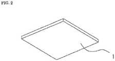
- FIG. 2 shows an example of the light emitting device 1 as an illumination device.
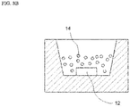
- FIG. 3A shows an example of the light emitting device 1 as an LED package.
- a plurality of LED packages shown in FIG. 3A is mounted in the light emitting device 1 serving as an illumination device shown in FIG. 2 .
- the LED package including a plurality of light emitting elements 12 and a plurality of fluorescent materials 14 a plurality of LED packages including one light emitting element 12 and one or a plurality of fluorescent materials 14 may be mounted, as shown in FIG. 3B .
- the light emitting device 1 can change the correlated color temperature of emitted light (hereinafter referred to as "emitting light"). Actually, the mechanism to control this change may be incorporated in the light emitting device 1, or may be realized by an external device connected to the light emitting device 1. The light emitting device 1 can emit at least emitting light having different correlated color temperatures.
- the emitting light is illumination emitted from the illumination device.
- the emitting light is, for example, a backlight.
- the emitting light is light emitted from the package to the outside.
- the light emitting device 1 includes one or a plurality of light emitting elements 12, and a plurality of fluorescent materials 14.
- the light emitting device 1 also includes a plurality of types of fluorescent materials 14 having different compositions.
- the light emitting device 1 also uses one or a plurality of light emitting elements 12 and one or a plurality of fluorescent materials 14, which are selected from the one or a plurality of light emitting elements 12 and the plurality of fluorescent materials 14, to thereby emit a plurality of lights having different light emission spectra from each other.
- the light emitting device 1 can also change the correlated color temperature within a predetermined range by adjusting the ratio of the plurality of lights and combining them.
- the light emitted from the selected one or a plurality light emitting elements 12 and the one or a plurality fluorescent materials 14 is referred to as single light.
- the light emitting device 1 emits a plurality of single lights having different light emission spectra from each other.
- the light obtained by combining a plurality of single lights is referred to as mixed light.
- the light emitting device 1 can emit single light or mixed light as the emitting light.
- the first light has a color rendering index R9 of 50 or more.
- the first light has a color rendering index R9 of 60 or more. More preferably, the first light has a color rendering index R9 of 65 or more.
- the color rendering index R9 is a value used for evaluating the color rendering property of red.
- the second light emitting device not only achieves a higher MR value than that of the conventional one by the third light, but also has a good color rendering index R9 value. Furthermore, the color rendering index R15 value is also excellent.
- Table 5 6500K 5000K 4000K 3500K 3000K 2700K Ra 98 94 97 97 96 96 R9 98 86 90 86 77 68 R15 95 95 99 99 97 94 MR 1.09 0.86 0.77 0.67 0.59 0.52
- the light emitting device 1 also achieves a color rendering index R9 of 90 or more and an MR value of 1.05 or more in the light having a correlated color temperature of 6,500 K composed of two or more lights including at least the third light among the first light, the second light, and the third light.
- the light emitting device 1 has an MR variation width of 0.55 or more and a color rendering index R9 of 65 or more in the correlated color temperature range of 2,700 K or more and 6,500 K or less.
- the MR value monotonically increases as the correlated color temperature increases.
- the MR value may not increase linearly as long as it increases monotonically.
- the information processing device 2 has a dimming determination unit 3 that determines a control command for adjusting illumination light emitted by the light emitting device 1.
- the dimming determination unit 3 determines the light emission ratio for emitting a plurality of single lights from the light emitting device 1 when controlling the correlated color temperature in the range from the first value to the second value.
Landscapes
- Physics & Mathematics (AREA)
- Spectroscopy & Molecular Physics (AREA)
- Engineering & Computer Science (AREA)
- General Engineering & Computer Science (AREA)
- Led Device Packages (AREA)
- Luminescent Compositions (AREA)
Abstract
Description
- This application claims priority to
Japanese Patent Application No. 2020-113376, filed on June 30, 2020 - The present disclosure relates to a light emitting device.
- Light, such as illumination and displays, has become an essential element in human work spaces. There are many hours in a day to receive light from inside buildings, computer equipment.
- In recent years, there has been a movement to emphasize considering the influence on a human body in shaping a human work environment. One of them is, for example, a certification system called WELL certification (Well Building Standard) established by IWBI (International WELL Building Institute). WELL certification evaluates buildings such as offices on multiple items, such as air, water, food, light, and comfort, and gives certification if they meet the criteria. Examples of the verification item of light in WELL certification include consideration for the visual environment, consideration for circadian, consideration for glare from fixtures and sunlight, and color rendering properties.
- Japanese Translation of PCT International Application Publication No.
2018-511386 - The present disclosure has an object to provide a light emitting device in consideration of circadian rhythm and color rendering properties.
- The light emitting device disclosed in the embodiment comprises one or a plurality of light emitting elements and a plurality of fluorescent materials, and emits a first light from one or a plurality of light emitting elements and one or a plurality of first fluorescent materials among the one or a plurality of light emitting elements and the plurality of fluorescent materials, a second light from one or a plurality of light emitting elements and one or a plurality of second fluorescent materials containing at least a fluorescent material different from the first fluorescent materials among the one or a plurality of light emitting elements and the plurality of fluorescent materials, and a third light from one or a plurality of light emitting elements and one or a plurality of third fluorescent materials containing at least a fluorescent material different from the first fluorescent materials and the second fluorescent materials among the one or a plurality of light emitting elements and the plurality of fluorescent materials, wherein the first light has a first color temperature with a correlated color temperature in a range of 1,500 K or more and 3,500 K or less, and has a color rendering index R9 of 50 or more, the second light has a second color temperature with a correlated color temperature in a range of 3,500 K or more and 5,500 K or less that is higher than the first color temperature, and has a color rendering index R9 of 50 or more, the third light has values of X and Y coordinates in the chromaticity diagram of the CIE1931 color system that are smaller than the values of X and Y coordinates at a color temperature of 5,500 K on the black body radiation locus, and a light having a correlated color temperature of 6,500 K composed of two or more lights including at least the third light among the first light, the second light, and the third light, has a color rendering index R9 of 50 or more and a melanopic ratio of 1.0 or more.
- In accordance with the present disclosure, a light emitting device in consideration of circadian rhythm and color rendering properties can be provided.
-
-
FIG. 1 is a graph showing curves of a circadian response and a visual sensitivity response. -
FIG. 2 is a schematic perspective view showing an example of the light emitting device according to the embodiment. -
FIG. 3A is a schematic cross-sectional view showing another example of the light emitting device according to the embodiment. -
FIG. 3B is a schematic cross-sectional view showing an example of the LED package according to the embodiment. -
FIG. 4 is a graph showing an example of the light emission spectrum of the first light in the light emitting device according to the embodiment. -
FIG. 5 is a graph showing an example of the light emission spectrum of the second light in the light emitting device according to the embodiment. -
FIG. 6 is a graph showing another example of the light emission spectrum of the second light in the light emitting device according to the embodiment. -
FIG. 7 is a graph showing another example of the light emission spectrum of the second light in the light emitting device according to the embodiment. -
FIG. 8 is a graph showing an example of the light emission spectrum of the third light in the light emitting device according to the embodiment. -
FIG. 9 is a system constitution diagram showing an example of the toning control system according to the embodiment. -
FIG. 10 is a block diagram for explaining the hardware constitution of the information processing device. - First, the effect of illumination on a human body will be described.
- As an example, the WELL certification described in the background requires an illumination design in consideration of circadian. Here, consideration of circadian means consideration of circadian rhythm.
- The circadian rhythm of human beings is longer than one day and is approximately 25 hours, and when it is not adjusted to one day, that is, a 24 hours cycle, the rhythm cycle deviates from one day. Light thus plays an important role as a synchronization factor for adjusting to 24 hours. The human biological clock is adjusted to 24 hours by being exposed to the sunlight, which naturally causes people to live in the rhythm of one day, such as waking up in the morning and going to sleep at night.
- In other words, the human body is equipped with a synchronization function utilizing light in order to live in a 24-hour rhythm. Specifically, there is a very small area in the hypothalamus of the brain called the suprachiasmatic nucleus, which plays the role of the biological clock that controls circadian rhythm. In addition, as a cell for giving a light signal to the suprachiasmatic nucleus, there is an intrinsically photosensitive retinal ganglion cell (hereinafter referred to as "ipRGC") on the retina.
- The ipRGC contains a photoreceptor protein called melanopsin, and it has been clarified that melanopsin is involved in the light synchronization of circadian rhythm. Melanopsin has absorption characteristics according to the wavelength of light, and the peak is in the vicinity of 480 to 490 nm.
- Melanopsin is also involved in secretion or suppression of melatonin which is a sleep promoting hormone, and it is considered that, for example, the secretion of melatonin is suppressed by increasing the amount of stimulation to the ipRGC. Normally, the peak of melatonin secretion in the body comes at night, and the secretion of melatonin promotes sleep. The secretion of melatonin is thus suppressed during the day.
- The WELL certification introduces an equivalent melanopic lux (hereinafter referred to as "EML") in order to evaluate whether or not the illumination design is in consideration of circadian. The EML is calculated by the following formula (1):

- The melanopic ratio (hereinafter referred to as "MR") in the formula (1) is calculated by the following formula (2):

FIG. 1 is a graph showing curves of a circadian response and a visual sensitivity response. - As seen from the formula (1), there are two possible ways of increasing the EML value: increasing illuminance or increasing MR. Further, it can be seen that the dependence on the characteristics of circadian rhythm is larger in MR than in illuminance. Therefore, in consideration of circadian rhythm, it can be considered that considering the MR value is preferred.
- Embodiments for carrying out the present disclosure will be hereunder described with reference to the drawings. The embodiments described below are intended to embody the technical idea of the present disclosure and are not intended to limit the present disclosure. Further, in the following description, the same name or symbol represents the same or equivalent member, and detailed description thereof will be omitted as appropriate. The sizes and positional relationships of members shown in each drawing may be exaggerated for clarity of explanation.
- The relationship between color names and chromaticity coordinates, and the relationship between wavelength ranges of light and color names of monochromic light are in accordance with Japanese Industrial Standard (JIS) Z8110. Further, the color rendering index is in accordance with JIS Z8726. In this specification, the "fluorescent material" is used in the same meaning as a "fluorescent phosphor".
- A
light emitting device 1 according to the embodiment will be described. Thelight emitting device 1 is, for example, an illumination device. It is also, for example, a display device such as a television or a computer display. It is also, for example, a package equipped with a light emitting element such as an LED (light emitting diode) that is mounted on an illumination device or a display device. It is not limited to these. -
FIG. 2 shows an example of thelight emitting device 1 as an illumination device.FIG. 3A shows an example of thelight emitting device 1 as an LED package. For example, a plurality of LED packages shown inFIG. 3A is mounted in thelight emitting device 1 serving as an illumination device shown inFIG. 2 . For example, instead of the LED package including a plurality oflight emitting elements 12 and a plurality offluorescent materials 14, a plurality of LED packages including onelight emitting element 12 and one or a plurality offluorescent materials 14 may be mounted, as shown inFIG. 3B . - The
light emitting device 1 can change the correlated color temperature of emitted light (hereinafter referred to as "emitting light"). Actually, the mechanism to control this change may be incorporated in thelight emitting device 1, or may be realized by an external device connected to thelight emitting device 1. Thelight emitting device 1 can emit at least emitting light having different correlated color temperatures. - In the case where the
light emitting device 1 is an illumination device, the emitting light is illumination emitted from the illumination device. In the case where thelight emitting device 1 is a display device, the emitting light is, for example, a backlight. In the case where thelight emitting device 1 is a package, the emitting light is light emitted from the package to the outside. - The
light emitting device 1 includes one or a plurality oflight emitting elements 12, and a plurality offluorescent materials 14. Thelight emitting device 1 also includes a plurality of types offluorescent materials 14 having different compositions. Thelight emitting device 1 also uses one or a plurality oflight emitting elements 12 and one or a plurality offluorescent materials 14, which are selected from the one or a plurality oflight emitting elements 12 and the plurality offluorescent materials 14, to thereby emit a plurality of lights having different light emission spectra from each other. Thelight emitting device 1 can also change the correlated color temperature within a predetermined range by adjusting the ratio of the plurality of lights and combining them. - For example, the
light emitting device 1 can change the correlated color temperature in a range of 2,700 K or more and 6,500 K or less. The range of the correlated color temperature that can be changed in thelight emitting device 1 is not limited to the above. For example, it may be in a range of 3,000 K or more and 6,000 K or less. - Here, the light emitted from the selected one or a plurality
light emitting elements 12 and the one or aplurality fluorescent materials 14 is referred to as single light. In other words, it can be said that thelight emitting device 1 emits a plurality of single lights having different light emission spectra from each other. In addition, the light obtained by combining a plurality of single lights is referred to as mixed light. Thelight emitting device 1 can emit single light or mixed light as the emitting light. - The plurality of single lights emitted from the
light emitting device 1 is respectively plotted at a different chromaticity coordinate in the chromaticity diagram of the CIE1931 color system (hereinafter simply referred to as "chromaticity diagram"). In other words, the plurality of single lights is respectively a light having a different chromaticity coordinate in the chromaticity diagram. - At least two or more single lights out of the plurality of single lights use one or more fluorescent materials different from each other. One or more of the same fluorescent materials may be used. All single lights may use one or more fluorescent materials different from each other.
- The plurality of single lights emitted by the
light emitting device 1 includes at least three single lights. Here, the three single lights are respectively referred to as a first light, a second light, and a third light. Each light will be hereunder described. - The first light is a light having a correlated color temperature in a range of 1,500 K or more and 3,500 K or less. Here, when indicating the correlated color temperature for a specific light, unless otherwise specified, it is assumed to indicate the correlated color temperature having a color deviation in a range of ±0.02.
- The first light has an average color rendering index Ra of 80 or more. Preferably, the first light has an average color rendering index Ra of 90 or more. More preferably, the first light has an average color rendering index Ra of 95 or more.
- The first light has a color rendering index R9 of 50 or more. Preferably, the first light has a color rendering index R9 of 60 or more. More preferably, the first light has a color rendering index R9 of 65 or more. The color rendering index R9 is a value used for evaluating the color rendering property of red.
- The first light has a color rendering index R15 of 75 or more. Preferably, the first light has a color rendering index R15 of 85 or more. More preferably, the first light has a color rendering index R15 of 90 or more. The color rendering index R15 is a value used for evaluating the color rendering property of Japanese skin tones.
- The first light has an MR value of 0.70 or less. Preferably, the first light has an MR value of 0.60 or less. More preferably, the first light has an MR value of 0.55 or less.
- For example, the first light is emitted from a
light emitting device 12 which is a nitride semiconductor and has a light emission peak in a range of 410 nm or more and 490 nm or less, a rare earthaluminate fluorescent material 14 having a composition represented by a formula of Y3(Al,Ga)5O12:Ce and having a light emission peak in the vicinity of 496 nm as a main fluorescent material, and afluoride fluorescent material 14 having a composition represented by a formula of K2SiF6:Mn4+ and having a light emission peak in the vicinity of 630 nm. -
FIG. 4 shows a specific example of the light emission spectrum of the first light. The first light in this specific example has a correlated color temperature of 2,700 K, an average color rendering index Ra of 96, a color rendering index R9 of 68, a color rendering index R15 of 94, and an MR value of 0.51. The first light is a light that is excellent in the values of the average color rendering index Ra and the color rendering index R15, and has a good value of the color rendering index R9 and a low MR value. - Here, as for the average color rendering index Ra, a value in a range of 80 or more and less than 90 is considered good, and a value of 90 or more is considered excellent. As for the color rendering index R9, a value in a range of 50 or more and less than 70 is considered good, and a value of 70 or more is considered excellent. As for the color rendering index R15, a value in a range of 75 or more and less than 85 is considered good, and a value of 85 or more is considered excellent. In the case where the value is below the range considered to be good, it is considered to be not good.
- The second light is a light having a correlated color temperature in a range of 3,500 K or more and 5,500 K or less. The second light is also a light having a correlated color temperature in a range of 3,500 K or more and 4,500 K or less. The second light is also a light having a correlated color temperature in a range of 4,500 K or more and 5,500 K or less.
- The second light has an average color rendering index Ra of 80 or more. Preferably, the second light has an average color rendering index Ra of 90 or more. More preferably, the second light has an average color rendering index Ra of 95 or more.
- The second light has a color rendering index R9 of 50 or more. Preferably, the second light has a color rendering index R9 of 70 or more. More preferably, the second light has a color rendering index R9 of 80 or more.
- The second light has a color rendering index R15 of 75 or more. Preferably, the second light has a color rendering index R15 of 85 or more. More preferably, the second light has a color rendering index R15 of 90 or more. Particularly preferably, the second light has a color rendering index R15 of 95 or more.
- The second light has an MR value in a range of 0.55 or more and 1.00 or less. Preferably, the second light has an MR value in a range of 0.60 or more and 0.90 or less. More preferably, the second light has an MR value in a range of 0.65 or more and 0.75 or less.
- For example, the second light is emitted from a
light emitting device 12 which is a nitride semiconductor and has a light emission peak in a range of 410 nm or more and 490 nm or less, a rare earth aluminumgarnet fluorescent material 14 having a composition represented by a formula of Lu3Al5O12:Ce and having a light emission peak in the vicinity of 520 nm as a main fluorescent material, and afluoride fluorescent material 14 having a composition represented by a formula of K2SiF6:Mn4+ and having a light emission peak in the vicinity of 630 nm. -
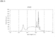
FIG. 5 shows a specific example of the light emission spectrum of the second light emitted from the above-mentionedlight emitting element 12 and thefluorescent materials 14. The second light in this specific example has a correlated color temperature of 4,000 K, an average color rendering index Ra of 94, a color rendering index R9 of 82, a color rendering index R15 of 95, and an MR value of 0.69. The second light is a light having excellent values of the average color rendering index Ra, the color rendering index R9, and the color rendering index R15. - For example, the second light is also emitted from a
light emitting device 12 which is a nitride semiconductor and has a light emission peak in a range of 410 nm or more and 490 nm or less, a rare earthaluminate fluorescent material 14 having a composition represented by a formula of Y3(Al,Ga)5O12:Ce and having a light emission peak in the vicinity of 520 nm as a main fluorescent material, and afluoride fluorescent material 14 having a composition represented by a formula of K2SiF6:Mn4+ and having a light emission peak in the vicinity of 630 nm. -
FIG. 6 shows another specific example of the light emission spectrum of the second light emitted from the above-mentionedlight emitting element 12 and thefluorescent materials 14. The second light in this specific example has a correlated color temperature of 5,000 K, an average color rendering index Ra of 94, a color rendering index R9 of 86, a color rendering index R15 of 95, and an MR value of 0.85. The second light is a light having excellent values of the average color rendering index Ra, the color rendering index R9, and the color rendering index R15. -
FIG. 7 shows another specific example of the light emission spectrum of the second light emitted from the above-mentionedlight emitting element 12 and thefluorescent materials 14. The second light in this specific example has a correlated color temperature of 3,500 K, an average color rendering index Ra of 95, a color rendering index R9 of 79, a color rendering index R15 of 96, and an MR value of 0.62. The second light is a light having excellent values of the average color rendering index Ra, the color rendering index R9, and the color rendering index R15. - The third light is a light of which the values of X and Y coordinates in the chromaticity diagram are plotted to values that are smaller than those of X and Y coordinates at a color temperature of 5,500 K on the black body radiation locus. The third light is also a light that is not plotted in a range where the correlated color temperature is 6,500 K or less in the chromaticity diagram. The third light is also a light that is not plotted in a range where the correlated color temperature is 8,000 K or less in the chromaticity diagram.
- The third light has an MR value of 1.80 or more. Preferably, the third light has an MR value of 2.00 or more. More preferably, the third light has an MR value of 2.20 or more. The third light also has an MR value of 3.00 or less.
- The third light has a color rendering index R9 of less than 50. Alternatively, the third light has a color rendering index R9 of less than 30. Alternatively, the third light has a color rendering index R9 of less than 10.
- The third light has a color rendering index R15 of less than 50. Alternatively, the third light has a color rendering index R15 of less than 30. Alternatively, the third light has a color rendering index R15 of less than 10.
- The third light is emitted from a
light emitting device 12 which is a nitride semiconductor and has a light emission peak in a range of 410 nm or more and 490 nm or less, and an alkaline earth metalaluminate fluorescent material 14 having a composition represented by a formula of Sr4Al14O25:Eu and having a light emission peak in the vicinity of 495 nm as a main fluorescent material. -
FIG. 8 shows a specific example of the light emission spectrum of the third light. The third light in this specific example has an X coordinate of 0.146 and a Y coordinate of 0.237 in the chromaticity diagram, and has an MR value of 2.84. Further, the third light has a color rendering index R9 of 0, and a color rendering index R15 of 0. As shown inFIG. 8 , the third light is a light having a high MR value corresponding to the circadian response. While the third light is specialized for MR, it is not good for the color rendering index R9 and the color rendering index R15. - Next, in the
light emitting device 1, the changes in the values of the average color rendering index Ra, the color rendering index R9, the color rendering index R15, and the MR value when changing the correlated color temperature by using the first light, the second light, and the third light, will be described. Prior to this description, a conventional light emitting device to be compared (hereinafter referred to as "comparative light emitting device") will be described. This comparative light emitting device is a light emitting device selected in terms of the balance between good luminous efficiency and high average color rendering index Ra, which is adopted in conventional illumination devices. - The comparative light emitting device is composed of two single lights having a correlated color temperature of 2,700 K and 6,500 K, respectively. Each of the single lights is emitted from: a
light emitting element 12 which is a nitride semiconductor and has a light emission peak in a range of 410 nm or more and 490 nm or less; and fluorescent materials including a rare earth aluminate fluorescent material having a composition represented by a formula of Y3Al5O12:Ce, a rare earth aluminate fluorescent material having a composition represented by a formula of Lu3Al5O12:Ce, and a silicon nitride fluorescent material having a composition represented by a formula of (SrCa)AlSiN3:Eu. - The comparative light emitting device achieves an average color rendering index Ra of 80 or more and a luminous efficiency of 180 to 200 lm/W in the correlated color temperature range of 2,700 K or more and 6,500 K or less. On the other hand, the MR value is below 1.00 at the maximum. The variation width of the MR value is less than 0.55 in the correlated color temperature range of 2,700 K or more and 6,500 K or less. The detailed values of the average color rendering index Ra, the color rendering index R9, the color rendering index R15, and the MR value at predetermined correlated color temperatures are shown in Table 1 below.
Table 1 6500K 5000K 4000K 3500K 3000K 2700K Ra 84 86 86 85 83 82 R9 10 21 23 19 9 4 R15 77 81 81 79 74 72 MR 0.95 0.82 0.70 0.62 0.52 0.44 - Next, a light emitting device obtained by using the comparative light emitting device and replacing the single light having a correlated color temperature of 6,500 K adopted in the comparative light emitting device with the third light specialized for MR, will be described as a reference. This light emitting device is referred to as a first reference light emitting device.
- The first reference light emitting device has an average color rendering index Ra of 80 or more and an MR value of more than 1.20 at the maximum in the correlated color temperature range of 2,700 K or more and 6,500 K or less. The variation width of the MR value is more than 0.80 in the correlated color temperature range of 2,700 K or more and 6,500 K or less. This means that a higher MR value is achieved by the third light. On the other hand, the value of the color rendering index R9 is less than 50 at the correlated color temperature of 3,500 K or less, and the value of the color rendering index R15 is less than 75 at the correlated color temperature of 2,700 K. The detailed values of the average color rendering index Ra, the color rendering index R9, the color rendering index R15, and MR at predetermined correlated color temperatures are shown in Table 2 below.
Table 2 6500K 5000K 4000K 3500K 3000K 2700K Ra 86 88 91 89 84 81 R9 91 75 52 30 12 -1 R15 91 95 92 84 76 70 MR 1.23 1.01 0.81 0.65 0.51 0.42 - Next, a light emitting device obtained by using the first reference light emitting device and replacing the single light having a correlated color temperature of 2,700 K adopted in the first reference light emitting device (also adopted in the comparative light emitting device) with the first light having a good color rendering index R9 value, will be described as a reference. This light emitting device is referred to as a second reference light emitting device.
- The second reference light emitting device has an average color rendering index Ra of 75 or more and an MR value of more than 1.20 at the maximum in the correlated color temperature range of 2,700 K or more and 6,500 K or less. The variation width of the MR value is more than 0.75 in the correlated color temperature range of 2,700 K or more and 6,500 K or less. Similar to the first reference light emitting device, a higher MR value is achieved by the third light. On the other hand, the value of the color rendering index R9 is less than 50 at the correlated color temperature of 6,500 K, and the value of the color rendering index R15 is less than 85 at the correlated color temperature of 4,000 K or more. The detailed values of the average color rendering index Ra, the color rendering index R9, the color rendering index R15, and MR at predetermined correlated color temperatures are shown in Table 3 below.
Table 3 6500K 5000K 4000K 3500K 3000K 2700K Ra 79 82 85 89 93 96 R9 41 56 75 90 84 68 R15 75 79 84 90 98 94 MR 1.28 1.08 0.90 0.78 0.62 0.51 - Next, a first light emitting device, which is an example of the
light emitting device 1, will be described. The first light emitting device is the light emittingdevice 1, which adopts the first light shown inFIG. 4 , the second light shown inFIG. 5 , and the third light shown inFIG. 8 . - The first light emitting device has an average color rendering index Ra of 90 or more and an MR value of more than 1.10 at the maximum in the correlated color temperature range of 2,700 K or more and 6,500 K or less. The variation width of the MR value is more than 0.60 in the correlated color temperature range of 2,700 K or more and 6,500 K or less. The color rendering index R9 is 60 or more in the correlated color temperature range of 2,700 K or more and 6,500 K or less, 70 or more at the correlated color temperature of 3,000 K or more, and 80 or more at the correlated color temperature of 3,500 K or more. The color rendering index R15 is 90 or more in the correlated color temperature range of 2,700 K or more and 6,500 K or less.
- The first light emitting device not only achieves a higher MR value than that of the conventional one by the third light, but also has a good color rendering index R9 value. Furthermore, the color rendering index R15 value is also excellent. The detailed values of the average color rendering index Ra, the color rendering index R9, the color rendering index R15, and MR at predetermined correlated color temperatures are shown in Table 4 below.
Table 4 6500K 5000K 4000K 3500K 3000K 2700K Ra 94 98 94 96 97 96 R9 84 97 82 81 76 68 R15 91 96 95 97 96 94 MR 1.15 0.93 0.70 0.64 0.58 0.52 - Next, a second light emitting device, which is an example of the
light emitting device 1, will be described. The second light emitting device is the light emittingdevice 1, which adopts the first light shown inFIG. 4 , the second light shown inFIG. 6 , and the third light shown inFIG. 8 . - The second light emitting device has an average color rendering index Ra of 90 or more and an MR value of more than 1.00 at the maximum in the correlated color temperature range of 2,700 K or more and 6,500 K or less. The variation width of the MR value is more than 0.55 in the correlated color temperature range of 2,700 K or more and 6,500 K or less. The color rendering index R9 is 60 or more in the correlated color temperature range of 2,700 K or more and 6,500 K or less, 70 or more at the correlated color temperature of 3,000 K or more, and 80 or more at the correlated color temperature of 3,500 K or more. The color rendering index R15 is 90 or more in the correlated color temperature range of 2,700 K or more and 6,500 K or less.
- The second light emitting device not only achieves a higher MR value than that of the conventional one by the third light, but also has a good color rendering index R9 value. Furthermore, the color rendering index R15 value is also excellent. The detailed values of the average color rendering index Ra, the color rendering index R9, the color rendering index R15, and MR at predetermined correlated color temperatures are shown in Table 5 below.
Table 5 6500K 5000K 4000K 3500K 3000K 2700K Ra 98 94 97 97 96 96 R9 98 86 90 86 77 68 R15 95 95 99 99 97 94 MR 1.09 0.86 0.77 0.67 0.59 0.52 - In view of the overall correlated color temperature range of 2,700 K or more and 6,500 K or less, the second light emitting device tends to have a slightly lower MR value, but a slightly higher color rendering index R9 value, compared to the first light emitting device. The color rendering index R15 value also tends to be slightly higher. That is, it can be said that the second light emitting device emphasizes the value of the color rendering index R9 or the color rendering index R15, compared to the first light emitting device.
- Next, a third light emitting device, which is an example of the
light emitting device 1, will be described. The third light emitting device is the light emittingdevice 1, which adopts the first light shown inFIG. 4 , the second light shown inFIG. 7 , and the third light shown inFIG. 8 . - The third light emitting device has an average color rendering index Ra of 90 or more and an MR value of more than 1.10 at the maximum in the correlated color temperature range of 2,700 K or more and 6,500 K or less. The variation width of the MR value is more than 0.65 in the correlated color temperature range of 2,700 K or more and 6,500 K or less. The color rendering index R9 is 60 or more in the correlated color temperature range of 2,700 K or more and 6,500 K or less, and 70 or more at the correlated color temperature of 3,000 K or more. The color rendering index R15 is 80 or more in the correlated color temperature range of 2,700 K or more and 6,500 K or less, and 90 or more at the correlated color temperature of 5,000 K or less.
- The third light emitting device not only achieves a higher MR value than that of the conventional one by the third light, but also has a good color rendering index R9 value. Furthermore, the color rendering index R15 value is also excellent. The detailed values of the average color rendering index Ra, the color rendering index R9, the color rendering index R15, and MR at predetermined correlated color temperatures are shown in Table 6 below.
Table 6 6500K 5000K 4000K 3500K 3000K 2700K Ra 90 94 97 95 96 96 R9 71 85 96 79 74 68 R15 87 91 97 96 96 94 MR 1.19 0.97 0.77 0.62 0.57 0.52 - In view of the overall correlated color temperature range of 2,700 K or more and 6,500 K or less, the third light emitting device tends to have a slightly higher MR value, but a slightly lower color rendering index R9 value, compared to the first light emitting device. The color rendering index R15 value also tends to be slightly low. That is, it can be said that the third light emitting device emphasizes the MR value compared to the first light emitting device.
- Accordingly, all of the first, second, and third light emitting devices achieve higher MR values and larger MR variation widths than those of the conventional one in the correlated color temperature range of 2,700 K or more and 6,500 K or less. The same applies to the first and second reference light emitting devices in this respect; and the first and second reference light emitting devices can achieve higher maximum MR values and larger MR variation widths than those of the first, second, and third light emitting devices. That is, from the viewpoint of MR, such light emitting devices can be expected to obtain superior effects compared to conventional ones.
- In addition, the first, second, and third light emitting devices exhibit good or excellent characteristics in terms of color rendering index R9 over a wide range of correlated color temperatures. In this respect, it can be said that the first, second, and third light emitting devices are superior to the first and second reference light emitting devices.
- The second light has a correlated color temperature in the range of 3,500 K or more and 5,500 K or less, and the MR value of the
light emitting device 1 at the correlated color temperature of 6,500 K becomes higher as the correlated color temperature of the second light is closer to the lower limit (3,500 K). The overall color rendering index R9 value also improves as the correlated color temperature of the second light is closer to the upper limit (5,500 K). - In other words, by changing the correlated color temperature of the second light, the balance between the MR value and the color rendering index R9 value can be appropriately adjusted. The same applies to the balance between the MR value and the color rendering index R15 value.
- The maximum value of the correlated color temperature achieved in the
light emitting device 1 may not be limited to 6,500 K. It may be more than 6,500 K or may be less than 6,500 K, but is higher than the correlated color temperature of the second light. The correlated color temperature of the first light can be equal to or less than the minimum value of the correlated color temperature achieved in thelight emitting device 1. In the case where the first light among the plurality of single lights provided in thelight emitting device 1 is a light having the lowest correlated color temperature, the correlated color temperature of the first light is equal to or less than the minimum value of the correlated color temperature achieved in thelight emitting device 1. - The
light emitting device 1 achieves a color rendering index R9 of 50 or more and an MR value of 1.0 or more in the light having a correlated color temperature of 6,500 K composed of two or more lights including at least the third light among the first light, the second light, and the third light. In addition, the color rendering index R15 value is 85 or more. Furthermore, thelight emitting device 1 achieves a color rendering index R9 of 50 or more in the light having a correlated color temperature of 2,700 K composed of one or more lights including at least the first light among the first light, the second light, and the third light. - The
light emitting device 1 also achieves a color rendering index R9 of 70 or more in the light having a correlated color temperature of 6,500 K composed of two or more lights including at least the third light among the first light, the second light, and the third light. - The
light emitting device 1 also achieves an MR value of 1.05 or more in the light having a correlated color temperature of 6,500 K composed of two or more lights including at least the third light among the first light, the second light, and the third light. - The
light emitting device 1 also achieves a color rendering index R9 of 80 or more and an MR value of 1.10 or more in the light having a correlated color temperature of 6,500 K composed of two or more lights including at least the third light among the first light, the second light, and the third light. - The
light emitting device 1 also achieves a color rendering index R9 of 90 or more and an MR value of 1.05 or more in the light having a correlated color temperature of 6,500 K composed of two or more lights including at least the third light among the first light, the second light, and the third light. - The
light emitting device 1 also achieves a color rendering index R9 of 70 or more and an MR value of 1.15 or more in the light having a correlated color temperature of 6,500 K composed of two or more lights including at least the third light among the first light, the second light, and the third light. - Further, the
light emitting device 1 has an MR variation width of 0.55 or more and a color rendering index R9 of 65 or more in the correlated color temperature range of 2,700 K or more and 6,500 K or less. The MR value monotonically increases as the correlated color temperature increases. The MR value may not increase linearly as long as it increases monotonically. - The
light emitting device 1 has an average color rendering index Ra of 80 or more in the correlated color temperature range of 2,700 K or more and 6,500 K or less. Thelight emitting device 1 also has a color rendering index R15 of 85 or more in the correlated color temperature range of 2,700 K or more and 6,500 K or less. The correlated color temperature of the first light is in a range of 1,500 K or more and 2,700 K or less. - The
light emitting device 1 has a color rendering index R9 of 75 or more in the correlated color temperature range of 3,500 K or more and 6,500 K or less. Thelight emitting device 1 also has a color rendering index R9 of 80 or more in the correlated color temperature range of 3,500 K or more and 6,500 K or less. Thelight emitting device 1 also has a color rendering index R9 of 85 or more in the correlated color temperature range of 3,500 K or more and 6,500 K or less. - Next, toning control performed using the
light emitting device 1 will be described. Here, a situation where a plurality of light emittingdevices 1 as illumination devices is installed in a living room in a building, is assumed. Thelight emitting device 1 as an illumination device is not limited to such a providing embodiment. - As long as the color temperature is within the range of the correlated color temperature that can be adjusted by the
light emitting device 1, theinformation processing device 2 that controls illumination by thelight emitting device 1 can perform toning within a desired range. In other words, the correlated color temperature of the illumination may be adjusted in a range smaller than the range where thelight emitting device 1 can perform toning. - The toning control system includes a plurality of light emitting
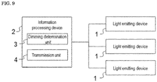
devices 1 and aninformation processing device 2. The plurality of light emittingdevices 1 and theinformation processing device 2 are communicably connected, and theinformation processing device 2 transmits control signals to thelight emitting devices 1 via communication means, thereby controlling the illumination by thelight emitting devices 1.FIG. 9 is a diagram showing an example of the constitution of the toning control system. The number of light emittingdevices 1 may be one. - The
information processing device 2 can be constituted by a computer, a server device, and the like.FIG. 10 is a diagram showing an example of the hardware constitution of theinformation processing device 2. Theinformation processing device 2 hasCPU 70,ROM 71,RAM 72,storage 73, graphics I/F 74, data I/F 75, communication I/F 76, andinput device 77, each of which is connected to the bus. - The
storage 73 is a storage medium capable of storing data non-volatilely. For example, a hard disk drive, a flash memory can be used. TheCPU 70 is a processor that executes processing in accordance with a program stored in theROM 71 and thestorage 73 by using theRAM 72 as a work memory. The graphics I/F 74 is an interface that converts generated display control signals into signals that can be displayed by the device and outputs the signals. - The data I/
F 75 is an interface for inputting data from the outside. For example, an interface such as USB can be applied. The communication I/F 76 is an interface for communicating with a network using a predetermined protocol. Theinput device 77 receives user input and outputs predetermined control signals. - In the toning control system, the
information processing device 2 has a dimmingdetermination unit 3 that determines a control command for adjusting illumination light emitted by thelight emitting device 1. The dimmingdetermination unit 3 determines the light emission ratio for emitting a plurality of single lights from thelight emitting device 1 when controlling the correlated color temperature in the range from the first value to the second value. - The
information processing device 2 also has atransmission unit 4 that transmits a control command for instructing light emission at a determined light emission ratio. Thelight emitting device 1 emits illumination based on the control command received from theinformation processing device 2. - In order to perform toning in accordance with the circadian rhythm, the toning is preferably performed corresponding to the change in the color temperature of sunlight. However, the toning may not be accurately performed according to the change of sunlight. For example, the correlated color temperature is linearly increased from 4,000 K to 6,500 K during 6:00 to 10:00 in a day to reach 6,500 K at 10:00. Thereafter, the correlated color temperature is maintained at 6,500 K until 14:30, and linearly decreased from 6,500 K to 4,000 K during 14:30 to 17:00. The correlated color temperature is further decreased from 4,000 K to 2,700 K during 17:00 to 19:00.
- As described above, the
light emitting device 1 according to the embodiment is able to emit a light having a high color rendering index R9, that is, an emitting light having high color rendering properties in the red region. The emitting light having excellent red reproducibility can be thus utilized for lighting such as illumination and displays, thereby improving user visibility. - Since the
light emitting device 1 has an excellent melanopic ratio, it is also possible to consider the circadian rhythm of users. Thelight emitting device 1 is able to suppress variations in the value of the color rendering index R9 and maintain a good value even in toning control where the value of the melanopic ratio increases or decreases, and thus a light emitting device in consideration of circadian rhythm and color rendering properties can be realized. - The light emitting device or toning control system according to the embodiment can be used in the fields of illumination and displays. It can also be used for electronic signboards and electronic advertisements. Further, it can also be used for information processing terminals that display augmented reality, virtual 3D space.
Claims (6)
- A light emitting device,
comprising one or a plurality of light emitting elements and a plurality of fluorescent materials; and
configured to emit
a first light from one or a plurality of light emitting elements and one or a plurality of first fluorescent materials among the one or a plurality of light emitting elements and the plurality of fluorescent materials,
a second light from one or a plurality of light emitting elements and one or a plurality of second fluorescent materials containing at least a fluorescent material different from the first fluorescent materials among the one or a plurality of light emitting elements and the plurality of fluorescent materials, and
a third light from one or a plurality of light emitting elements and one or a plurality of third fluorescent materials containing at least a fluorescent material different from the first fluorescent materials and the second fluorescent materials among the one or a plurality of light emitting elements and the plurality of fluorescent materials,
wherein the first light has a first color temperature with a correlated color temperature in a range of 1,500 K or more and 3,500 K or less, and has a color rendering index R9 of 50 or more,
the second light has a second color temperature with a correlated color temperature in a range of 3,500 K or more and 5,500 K or less that is higher than the first color temperature, and has a color rendering index R9 of 50 or more,
the third light has values of X and Y coordinates in the chromaticity diagram of the CIE1931 color system that are smaller than the values of X and Y coordinates at a color temperature of 5,500 K on the black body radiation locus, and
a light having a correlated color temperature of 6,500 K composed of two or more lights including at least the third light among the first light, the second light, and the third light, has a color rendering index R9 of 50 or more and a melanopic ratio of 1.0 or more. - The light emitting device according to claim 1, wherein the light having a correlated color temperature of 6,500 K composed of two or more lights including at least the third light among the first light, the second light, and the third light, has a color rendering index R15 of 85 or more.
- The light emitting device according to claim 1 or 2, wherein a light having a correlated color temperature in a range of 3,500 K or more and 5,500 K or less composed of one or more lights among the first light, the second light, and the third light, has a color rendering index R9 of 60 or more.
- The light emitting device according to any one of claims 1 to 3,
wherein the first color temperature has a correlated color temperature in a range of 1,500 K or more and 2,700 K or less, and
a light having a correlated color temperature in a range of 2,700 K or more and 6,500 K or less composed of one or more lights among the first light, the second light, and the third light, has an average color rendering index Ra of 80 or more. - The light emitting device according to claim 4, wherein the light having a correlated color temperature in a range of 2,700 K or more and 6,500 K or less composed of one or more lights among the first light, the second light, and the third light, has a melanopic ratio that is monotonically increased.
- The light emitting device according to any one of claims 1 to 5, wherein the third light has a color rendering index R9 of less than 30.
Priority Applications (1)
| Application Number | Priority Date | Filing Date | Title |
|---|---|---|---|
| EP22206870.2A EP4156311B1 (en) | 2020-06-30 | 2021-06-29 | Light emitting device |
Applications Claiming Priority (1)
| Application Number | Priority Date | Filing Date | Title |
|---|---|---|---|
| JP2020113376A JP7174266B2 (en) | 2020-06-30 | 2020-06-30 | light emitting device |
Related Child Applications (2)
| Application Number | Title | Priority Date | Filing Date |
|---|---|---|---|
| EP22206870.2A Division EP4156311B1 (en) | 2020-06-30 | 2021-06-29 | Light emitting device |
| EP22206870.2A Division-Into EP4156311B1 (en) | 2020-06-30 | 2021-06-29 | Light emitting device |
Publications (2)
| Publication Number | Publication Date |
|---|---|
| EP3933943A1 true EP3933943A1 (en) | 2022-01-05 |
| EP3933943B1 EP3933943B1 (en) | 2022-12-28 |
Family
ID=76890800
Family Applications (2)
| Application Number | Title | Priority Date | Filing Date |
|---|---|---|---|
| EP22206870.2A Active EP4156311B1 (en) | 2020-06-30 | 2021-06-29 | Light emitting device |
| EP21182546.8A Active EP3933943B1 (en) | 2020-06-30 | 2021-06-29 | Light emitting device |
Family Applications Before (1)
| Application Number | Title | Priority Date | Filing Date |
|---|---|---|---|
| EP22206870.2A Active EP4156311B1 (en) | 2020-06-30 | 2021-06-29 | Light emitting device |
Country Status (4)
| Country | Link |
|---|---|
| US (2) | US11598508B2 (en) |
| EP (2) | EP4156311B1 (en) |
| JP (2) | JP7174266B2 (en) |
| CN (1) | CN113871376A (en) |
Families Citing this family (7)
| Publication number | Priority date | Publication date | Assignee | Title |
|---|---|---|---|---|
| US20120022057A1 (en) | 2009-03-18 | 2012-01-26 | Schering Corporation | Bicyclic compounds as inhibitors of diacyglycerol acyltransferase |
| US20120172369A1 (en) | 2009-09-14 | 2012-07-05 | Ting Pauline C | Inhibitors of diacylglycerol acyltransferase |
| JP7824502B2 (en) * | 2020-03-31 | 2026-03-05 | 日亜化学工業株式会社 | Light-emitting device and lighting fixture equipped with same |
| JP7174266B2 (en) * | 2020-06-30 | 2022-11-17 | 日亜化学工業株式会社 | light emitting device |
| JP7185146B2 (en) * | 2020-09-15 | 2022-12-07 | 日亜化学工業株式会社 | light emitting device |
| JP7606639B1 (en) | 2024-03-28 | 2024-12-25 | 株式会社Maruwa | Light-emitting device and lighting fixture |
| TWI908192B (en) * | 2024-07-15 | 2025-12-11 | 星亞視覺股份有限公司 | Adjustment method for light emitting system and light emitting system |
Citations (4)
| Publication number | Priority date | Publication date | Assignee | Title |
|---|---|---|---|---|
| WO2016146688A1 (en) * | 2015-03-19 | 2016-09-22 | Philips Lighting Holding B.V. | Bio hue lamp |
| US20180077767A1 (en) * | 2016-09-13 | 2018-03-15 | Biological Innovation & Optimization Systems, LLC | Systems and methods for controlling the spectral content of led lighting devices |
| WO2020118280A1 (en) * | 2018-12-07 | 2020-06-11 | Lutron Technology Company Llc | Light source for maintaining circadian metrics while allowing flexibility in changing intensity and color temperature |
| JP2020098855A (en) * | 2018-12-18 | 2020-06-25 | シチズン時計株式会社 | LED light emitting device |
Family Cites Families (41)
| Publication number | Priority date | Publication date | Assignee | Title |
|---|---|---|---|---|
| JP4221950B2 (en) | 2002-05-23 | 2009-02-12 | 日亜化学工業株式会社 | Phosphor |
| JP2004161808A (en) | 2002-11-08 | 2004-06-10 | Nichia Chem Ind Ltd | Nitride-based fluorescent sheet, light-emitting device, and method for manufacturing nitride-based fluorescent film |
| US7737623B2 (en) | 2004-06-30 | 2010-06-15 | Mitsubishi Chemical Corporation | Light emitting device, lighting system, backlight unit for display device, and display device |
| JP5320655B2 (en) | 2004-06-30 | 2013-10-23 | 三菱化学株式会社 | LIGHT EMITTING DEVICE, LIGHTING, BACKLIGHT UNIT FOR DISPLAY DEVICE, AND DISPLAY DEVICE |
| EP2106198A1 (en) | 2006-12-08 | 2009-09-30 | Sharp Kabushiki Kaisha | Light source and light irradiating device |
| EP2211083A4 (en) | 2007-11-12 | 2014-06-25 | Mitsubishi Chem Corp | LIGHTING SYSTEM |
| JP2010267571A (en) | 2009-05-18 | 2010-11-25 | Toshiba Lighting & Technology Corp | Lighting device |
| JP5260424B2 (en) * | 2009-07-08 | 2013-08-14 | 株式会社ジャパンディスプレイ | Liquid crystal display |
| JP2013502047A (en) | 2009-08-14 | 2013-01-17 | キユーデイー・ビジヨン・インコーポレーテツド | LIGHTING DEVICE, OPTICAL COMPONENT AND METHOD FOR LIGHTING DEVICE |
| US8791642B2 (en) * | 2011-03-03 | 2014-07-29 | Cree, Inc. | Semiconductor light emitting devices having selectable and/or adjustable color points and related methods |
| JP5705623B2 (en) | 2011-04-08 | 2015-04-22 | シチズン電子株式会社 | Chromaticity adjustment type white light emitting device. |
| CN103493226B (en) | 2011-04-22 | 2016-09-28 | 株式会社东芝 | White light source and white light source system including said white light source |
| US9541242B2 (en) | 2012-03-01 | 2017-01-10 | Koninklijke Philips N.V. | LED lighting arrangement |
| JP3177205U (en) | 2012-05-11 | 2012-07-26 | 株式会社ボルクスジャパン | Lighting equipment for aquarium |
| KR20150022918A (en) | 2012-06-01 | 2015-03-04 | 쓰리엠 이노베이티브 프로퍼티즈 컴파니 | Hybrid light bulbs using combinations of remote phosphor leds and direct emitting leds |
| TWI662223B (en) * | 2012-12-07 | 2019-06-11 | 樂金顯示科技股份有限公司 | Lighting apparatus |
| JP6145679B2 (en) * | 2013-10-28 | 2017-06-14 | パナソニックIpマネジメント株式会社 | Light source module and lighting device |
| JP6548104B2 (en) | 2013-12-12 | 2019-07-24 | パナソニックIpマネジメント株式会社 | Light source module and light source unit |
| US9537062B2 (en) | 2013-12-17 | 2017-01-03 | Philips Lighting Holding B.V. | Solid state light emitter package, a light emission device, a flexible LED strip and a luminaire |
| CN104075162B (en) | 2014-07-04 | 2016-07-13 | 复旦大学 | A high color rendering white LED lighting system with adjustable color temperature |
| EP3546544B1 (en) | 2014-10-08 | 2024-05-01 | Seoul Semiconductor Co., Ltd. | Light emitting device |
| EP3316322B1 (en) | 2015-06-24 | 2023-12-13 | Seoul Semiconductor Co., Ltd. | White light source system |
| JP6435243B2 (en) | 2015-08-04 | 2018-12-05 | 日立アプライアンス株式会社 | Lighting device |
| WO2017106759A1 (en) * | 2015-12-18 | 2017-06-22 | Musco Corportion | Lighting optimized for melanopic vision |
| WO2018200685A2 (en) * | 2017-04-27 | 2018-11-01 | Ecosense Lighting Inc. | Methods and systems for an automated design, fulfillment, deployment and operation platform for lighting installations |
| CN109312911B (en) | 2016-01-28 | 2021-01-01 | 生态照明公司 | Method for generating melatonin-responsive tunable white light with high color rendering |
| EP3460860A4 (en) | 2016-05-20 | 2020-02-12 | Kabushiki Kaisha Toshiba | SOURCE OF WHITE LIGHT |
| JP6735514B2 (en) | 2016-11-29 | 2020-08-05 | パナソニックIpマネジメント株式会社 | Lighting equipment |
| JP7016038B2 (en) | 2017-07-26 | 2022-02-04 | パナソニックIpマネジメント株式会社 | Lighting equipment and lighting control system |
| WO2019050260A1 (en) | 2017-09-06 | 2019-03-14 | 지엘비텍 주식회사 | High color rendering d50/d65 standard led illuminant module and lighting apparatus |
| US10837607B2 (en) * | 2017-09-26 | 2020-11-17 | Lumileds Llc | Light emitting device with improved warm-white color point |
| KR102613239B1 (en) | 2018-06-04 | 2023-12-14 | 삼성전자주식회사 | White light emitting diode module and lighting apparatus |
| US10685941B1 (en) * | 2019-07-09 | 2020-06-16 | Intematix Corporation | Full spectrum white light emitting devices |
| EP4223366A3 (en) | 2018-08-31 | 2023-09-20 | Signify Holding B.V. | Cyan enriched white light |
| WO2020055119A1 (en) | 2018-09-12 | 2020-03-19 | 서울반도체주식회사 | Light-emitting device |
| JP7303437B2 (en) | 2018-09-28 | 2023-07-05 | 日亜化学工業株式会社 | Light-emitting device and lamp equipped with the same |
| CN111755429B (en) | 2019-03-29 | 2024-07-09 | 日亚化学工业株式会社 | Light-emitting device |
| JP7125618B2 (en) | 2019-03-29 | 2022-08-25 | 日亜化学工業株式会社 | light emitting device |
| CN210073838U (en) | 2019-05-23 | 2020-02-14 | 昕诺飞控股有限公司 | LED devices and corresponding lamps |
| US10697591B1 (en) * | 2019-08-30 | 2020-06-30 | Gregory Yeutter | Light bulb with controlled color and flicker |
| JP7174266B2 (en) | 2020-06-30 | 2022-11-17 | 日亜化学工業株式会社 | light emitting device |
-
2020
- 2020-06-30 JP JP2020113376A patent/JP7174266B2/en active Active
-
2021
- 2021-06-29 EP EP22206870.2A patent/EP4156311B1/en active Active
- 2021-06-29 EP EP21182546.8A patent/EP3933943B1/en active Active
- 2021-06-30 CN CN202110733638.6A patent/CN113871376A/en active Pending
- 2021-06-30 US US17/305,124 patent/US11598508B2/en active Active
-
2022
- 2022-11-02 JP JP2022176183A patent/JP7445164B2/en active Active
-
2023
- 2023-01-26 US US18/159,962 patent/US12287089B2/en active Active
Patent Citations (4)
| Publication number | Priority date | Publication date | Assignee | Title |
|---|---|---|---|---|
| WO2016146688A1 (en) * | 2015-03-19 | 2016-09-22 | Philips Lighting Holding B.V. | Bio hue lamp |
| US20180077767A1 (en) * | 2016-09-13 | 2018-03-15 | Biological Innovation & Optimization Systems, LLC | Systems and methods for controlling the spectral content of led lighting devices |
| WO2020118280A1 (en) * | 2018-12-07 | 2020-06-11 | Lutron Technology Company Llc | Light source for maintaining circadian metrics while allowing flexibility in changing intensity and color temperature |
| JP2020098855A (en) * | 2018-12-18 | 2020-06-25 | シチズン時計株式会社 | LED light emitting device |
Also Published As
| Publication number | Publication date |
|---|---|
| JP7445164B2 (en) | 2024-03-07 |
| US12287089B2 (en) | 2025-04-29 |
| US11598508B2 (en) | 2023-03-07 |
| JP2023011822A (en) | 2023-01-24 |
| EP4156311A1 (en) | 2023-03-29 |
| JP2022022660A (en) | 2022-02-07 |
| EP3933943B1 (en) | 2022-12-28 |
| US20230243485A1 (en) | 2023-08-03 |
| EP4156311B1 (en) | 2026-04-15 |
| JP7174266B2 (en) | 2022-11-17 |
| US20210404632A1 (en) | 2021-12-30 |
| CN113871376A (en) | 2021-12-31 |
Similar Documents
| Publication | Publication Date | Title |
|---|---|---|
| EP3933943B1 (en) | Light emitting device | |
| US10324250B2 (en) | Circadian-friendly LED light sources | |
| EP3483496B1 (en) | White light source and white light source system including the same | |
| CN112424962B (en) | Lighting | |
| KR102219769B1 (en) | Circadian-friendly led light source | |
| JP7311818B2 (en) | light emitting device | |
| CN102714260B (en) | Include the solid-state lighting device of light mixture | |
| JP7125618B2 (en) | light emitting device | |
| US11778705B2 (en) | Lighting control system | |
| JP7381960B2 (en) | light emitting device | |
| JP7510068B2 (en) | Lighting fixtures, dimming control systems | |
| CN109473534B (en) | Lighting element, lighting device, method for operating a lighting device, and conversion element | |
| JP2020174035A (en) | Lighting control system and lighting equipment. | |
| CN113757573A (en) | A light source module and lighting device | |
| CN221237741U (en) | Light source, light source module and lighting device | |
| JP7448829B2 (en) | lighting equipment | |
| CN216079367U (en) | Light source module and lighting device | |
| CN112747263B (en) | A light source module and a lighting device including the light source module | |
| CN113775944A (en) | Light source module and lighting device comprising same | |
| JP7790699B2 (en) | Illumination device for illuminating a color display - Patent Application 20070122997 |
Legal Events
| Date | Code | Title | Description |
|---|---|---|---|
| PUAI | Public reference made under article 153(3) epc to a published international application that has entered the european phase |
Free format text: ORIGINAL CODE: 0009012 |
|
| STAA | Information on the status of an ep patent application or granted ep patent |
Free format text: STATUS: THE APPLICATION HAS BEEN PUBLISHED |
|
| AK | Designated contracting states |
Kind code of ref document: A1 Designated state(s): AL AT BE BG CH CY CZ DE DK EE ES FI FR GB GR HR HU IE IS IT LI LT LU LV MC MK MT NL NO PL PT RO RS SE SI SK SM TR |
|
| B565 | Issuance of search results under rule 164(2) epc |
Effective date: 20211208 |
|
| STAA | Information on the status of an ep patent application or granted ep patent |
Free format text: STATUS: REQUEST FOR EXAMINATION WAS MADE |
|
| 17P | Request for examination filed |
Effective date: 20220506 |
|
| RBV | Designated contracting states (corrected) |
Designated state(s): AL AT BE BG CH CY CZ DE DK EE ES FI FR GB GR HR HU IE IS IT LI LT LU LV MC MK MT NL NO PL PT RO RS SE SI SK SM TR |
|
| GRAP | Despatch of communication of intention to grant a patent |
Free format text: ORIGINAL CODE: EPIDOSNIGR1 |
|
| STAA | Information on the status of an ep patent application or granted ep patent |
Free format text: STATUS: GRANT OF PATENT IS INTENDED |
|
| INTG | Intention to grant announced |
Effective date: 20220819 |
|
| RAP3 | Party data changed (applicant data changed or rights of an application transferred) |
Owner name: NICHIA CORPORATION |
|
| RIN1 | Information on inventor provided before grant (corrected) |
Inventor name: TAKAHASHI, JUN Inventor name: NIKI, KENTA |
|
| GRAS | Grant fee paid |
Free format text: ORIGINAL CODE: EPIDOSNIGR3 |
|
| GRAA | (expected) grant |
Free format text: ORIGINAL CODE: 0009210 |
|
| STAA | Information on the status of an ep patent application or granted ep patent |
Free format text: STATUS: THE PATENT HAS BEEN GRANTED |
|
| AK | Designated contracting states |
Kind code of ref document: B1 Designated state(s): AL AT BE BG CH CY CZ DE DK EE ES FI FR GB GR HR HU IE IS IT LI LT LU LV MC MK MT NL NO PL PT RO RS SE SI SK SM TR |
|
| REG | Reference to a national code |
Ref country code: GB Ref legal event code: FG4D |
|
| REG | Reference to a national code |
Ref country code: CH Ref legal event code: EP |
|
| REG | Reference to a national code |
Ref country code: DE Ref legal event code: R096 Ref document number: 602021001102 Country of ref document: DE |
|
| REG | Reference to a national code |
Ref country code: AT Ref legal event code: REF Ref document number: 1541024 Country of ref document: AT Kind code of ref document: T Effective date: 20230115 |
|
| REG | Reference to a national code |
Ref country code: IE Ref legal event code: FG4D |
|
| REG | Reference to a national code |
Ref country code: LT Ref legal event code: MG9D |
|
| PG25 | Lapsed in a contracting state [announced via postgrant information from national office to epo] |
Ref country code: SE Free format text: LAPSE BECAUSE OF FAILURE TO SUBMIT A TRANSLATION OF THE DESCRIPTION OR TO PAY THE FEE WITHIN THE PRESCRIBED TIME-LIMIT Effective date: 20221228 Ref country code: NO Free format text: LAPSE BECAUSE OF FAILURE TO SUBMIT A TRANSLATION OF THE DESCRIPTION OR TO PAY THE FEE WITHIN THE PRESCRIBED TIME-LIMIT Effective date: 20230328 Ref country code: LT Free format text: LAPSE BECAUSE OF FAILURE TO SUBMIT A TRANSLATION OF THE DESCRIPTION OR TO PAY THE FEE WITHIN THE PRESCRIBED TIME-LIMIT Effective date: 20221228 Ref country code: FI Free format text: LAPSE BECAUSE OF FAILURE TO SUBMIT A TRANSLATION OF THE DESCRIPTION OR TO PAY THE FEE WITHIN THE PRESCRIBED TIME-LIMIT Effective date: 20221228 |
|
| REG | Reference to a national code |
Ref country code: NL Ref legal event code: MP Effective date: 20221228 |
|
| REG | Reference to a national code |
Ref country code: AT Ref legal event code: MK05 Ref document number: 1541024 Country of ref document: AT Kind code of ref document: T Effective date: 20221228 |
|
| PG25 | Lapsed in a contracting state [announced via postgrant information from national office to epo] |
Ref country code: RS Free format text: LAPSE BECAUSE OF FAILURE TO SUBMIT A TRANSLATION OF THE DESCRIPTION OR TO PAY THE FEE WITHIN THE PRESCRIBED TIME-LIMIT Effective date: 20221228 Ref country code: LV Free format text: LAPSE BECAUSE OF FAILURE TO SUBMIT A TRANSLATION OF THE DESCRIPTION OR TO PAY THE FEE WITHIN THE PRESCRIBED TIME-LIMIT Effective date: 20221228 Ref country code: HR Free format text: LAPSE BECAUSE OF FAILURE TO SUBMIT A TRANSLATION OF THE DESCRIPTION OR TO PAY THE FEE WITHIN THE PRESCRIBED TIME-LIMIT Effective date: 20221228 Ref country code: GR Free format text: LAPSE BECAUSE OF FAILURE TO SUBMIT A TRANSLATION OF THE DESCRIPTION OR TO PAY THE FEE WITHIN THE PRESCRIBED TIME-LIMIT Effective date: 20230329 |
|
| P01 | Opt-out of the competence of the unified patent court (upc) registered |
Effective date: 20230522 |
|
| PG25 | Lapsed in a contracting state [announced via postgrant information from national office to epo] |
Ref country code: NL Free format text: LAPSE BECAUSE OF FAILURE TO SUBMIT A TRANSLATION OF THE DESCRIPTION OR TO PAY THE FEE WITHIN THE PRESCRIBED TIME-LIMIT Effective date: 20221228 |
|
| PG25 | Lapsed in a contracting state [announced via postgrant information from national office to epo] |
Ref country code: SM Free format text: LAPSE BECAUSE OF FAILURE TO SUBMIT A TRANSLATION OF THE DESCRIPTION OR TO PAY THE FEE WITHIN THE PRESCRIBED TIME-LIMIT Effective date: 20221228 Ref country code: RO Free format text: LAPSE BECAUSE OF FAILURE TO SUBMIT A TRANSLATION OF THE DESCRIPTION OR TO PAY THE FEE WITHIN THE PRESCRIBED TIME-LIMIT Effective date: 20221228 Ref country code: PT Free format text: LAPSE BECAUSE OF FAILURE TO SUBMIT A TRANSLATION OF THE DESCRIPTION OR TO PAY THE FEE WITHIN THE PRESCRIBED TIME-LIMIT Effective date: 20230428 Ref country code: ES Free format text: LAPSE BECAUSE OF FAILURE TO SUBMIT A TRANSLATION OF THE DESCRIPTION OR TO PAY THE FEE WITHIN THE PRESCRIBED TIME-LIMIT Effective date: 20221228 Ref country code: EE Free format text: LAPSE BECAUSE OF FAILURE TO SUBMIT A TRANSLATION OF THE DESCRIPTION OR TO PAY THE FEE WITHIN THE PRESCRIBED TIME-LIMIT Effective date: 20221228 Ref country code: CZ Free format text: LAPSE BECAUSE OF FAILURE TO SUBMIT A TRANSLATION OF THE DESCRIPTION OR TO PAY THE FEE WITHIN THE PRESCRIBED TIME-LIMIT Effective date: 20221228 Ref country code: AT Free format text: LAPSE BECAUSE OF FAILURE TO SUBMIT A TRANSLATION OF THE DESCRIPTION OR TO PAY THE FEE WITHIN THE PRESCRIBED TIME-LIMIT Effective date: 20221228 |
|
| PG25 | Lapsed in a contracting state [announced via postgrant information from national office to epo] |
Ref country code: SK Free format text: LAPSE BECAUSE OF FAILURE TO SUBMIT A TRANSLATION OF THE DESCRIPTION OR TO PAY THE FEE WITHIN THE PRESCRIBED TIME-LIMIT Effective date: 20221228 Ref country code: PL Free format text: LAPSE BECAUSE OF FAILURE TO SUBMIT A TRANSLATION OF THE DESCRIPTION OR TO PAY THE FEE WITHIN THE PRESCRIBED TIME-LIMIT Effective date: 20221228 Ref country code: IS Free format text: LAPSE BECAUSE OF FAILURE TO SUBMIT A TRANSLATION OF THE DESCRIPTION OR TO PAY THE FEE WITHIN THE PRESCRIBED TIME-LIMIT Effective date: 20230428 Ref country code: AL Free format text: LAPSE BECAUSE OF FAILURE TO SUBMIT A TRANSLATION OF THE DESCRIPTION OR TO PAY THE FEE WITHIN THE PRESCRIBED TIME-LIMIT Effective date: 20221228 |
|
| REG | Reference to a national code |
Ref country code: DE Ref legal event code: R097 Ref document number: 602021001102 Country of ref document: DE |
|
| PG25 | Lapsed in a contracting state [announced via postgrant information from national office to epo] |
Ref country code: DK Free format text: LAPSE BECAUSE OF FAILURE TO SUBMIT A TRANSLATION OF THE DESCRIPTION OR TO PAY THE FEE WITHIN THE PRESCRIBED TIME-LIMIT Effective date: 20221228 |
|
| PLBE | No opposition filed within time limit |
Free format text: ORIGINAL CODE: 0009261 |
|
| STAA | Information on the status of an ep patent application or granted ep patent |
Free format text: STATUS: NO OPPOSITION FILED WITHIN TIME LIMIT |
|
| 26N | No opposition filed |
Effective date: 20230929 |
|
| PG25 | Lapsed in a contracting state [announced via postgrant information from national office to epo] |
Ref country code: MC Free format text: LAPSE BECAUSE OF FAILURE TO SUBMIT A TRANSLATION OF THE DESCRIPTION OR TO PAY THE FEE WITHIN THE PRESCRIBED TIME-LIMIT Effective date: 20221228 |
|
| PG25 | Lapsed in a contracting state [announced via postgrant information from national office to epo] |
Ref country code: SI Free format text: LAPSE BECAUSE OF FAILURE TO SUBMIT A TRANSLATION OF THE DESCRIPTION OR TO PAY THE FEE WITHIN THE PRESCRIBED TIME-LIMIT Effective date: 20221228 Ref country code: MC Free format text: LAPSE BECAUSE OF FAILURE TO SUBMIT A TRANSLATION OF THE DESCRIPTION OR TO PAY THE FEE WITHIN THE PRESCRIBED TIME-LIMIT Effective date: 20221228 |
|
| REG | Reference to a national code |
Ref country code: BE Ref legal event code: MM Effective date: 20230630 |
|
| PG25 | Lapsed in a contracting state [announced via postgrant information from national office to epo] |
Ref country code: LU Free format text: LAPSE BECAUSE OF NON-PAYMENT OF DUE FEES Effective date: 20230629 |
|
| REG | Reference to a national code |
Ref country code: IE Ref legal event code: MM4A |
|
| PG25 | Lapsed in a contracting state [announced via postgrant information from national office to epo] |
Ref country code: LU Free format text: LAPSE BECAUSE OF NON-PAYMENT OF DUE FEES Effective date: 20230629 |
|
| PG25 | Lapsed in a contracting state [announced via postgrant information from national office to epo] |
Ref country code: IE Free format text: LAPSE BECAUSE OF NON-PAYMENT OF DUE FEES Effective date: 20230629 |
|
| PG25 | Lapsed in a contracting state [announced via postgrant information from national office to epo] |
Ref country code: IE Free format text: LAPSE BECAUSE OF NON-PAYMENT OF DUE FEES Effective date: 20230629 |
|
| PG25 | Lapsed in a contracting state [announced via postgrant information from national office to epo] |
Ref country code: IT Free format text: LAPSE BECAUSE OF FAILURE TO SUBMIT A TRANSLATION OF THE DESCRIPTION OR TO PAY THE FEE WITHIN THE PRESCRIBED TIME-LIMIT Effective date: 20221228 Ref country code: BE Free format text: LAPSE BECAUSE OF NON-PAYMENT OF DUE FEES Effective date: 20230630 |
|
| PG25 | Lapsed in a contracting state [announced via postgrant information from national office to epo] |
Ref country code: BG Free format text: LAPSE BECAUSE OF FAILURE TO SUBMIT A TRANSLATION OF THE DESCRIPTION OR TO PAY THE FEE WITHIN THE PRESCRIBED TIME-LIMIT Effective date: 20221228 |
|
| REG | Reference to a national code |
Ref country code: DE Ref legal event code: R079 Ref document number: 602021001102 Country of ref document: DE Free format text: PREVIOUS MAIN CLASS: H01L0033500000 Ipc: H10H0020851000 |
|
| PG25 | Lapsed in a contracting state [announced via postgrant information from national office to epo] |
Ref country code: BG Free format text: LAPSE BECAUSE OF FAILURE TO SUBMIT A TRANSLATION OF THE DESCRIPTION OR TO PAY THE FEE WITHIN THE PRESCRIBED TIME-LIMIT Effective date: 20221228 |
|
| REG | Reference to a national code |
Ref country code: CH Ref legal event code: PL |
|
| PG25 | Lapsed in a contracting state [announced via postgrant information from national office to epo] |
Ref country code: CH Free format text: LAPSE BECAUSE OF NON-PAYMENT OF DUE FEES Effective date: 20240630 |
|
| PGFP | Annual fee paid to national office [announced via postgrant information from national office to epo] |
Ref country code: DE Payment date: 20250507 Year of fee payment: 5 |
|
| PGFP | Annual fee paid to national office [announced via postgrant information from national office to epo] |
Ref country code: GB Payment date: 20250508 Year of fee payment: 5 |
|
| PGFP | Annual fee paid to national office [announced via postgrant information from national office to epo] |
Ref country code: FR Payment date: 20250508 Year of fee payment: 5 |
|
| PG25 | Lapsed in a contracting state [announced via postgrant information from national office to epo] |
Ref country code: CY Free format text: LAPSE BECAUSE OF FAILURE TO SUBMIT A TRANSLATION OF THE DESCRIPTION OR TO PAY THE FEE WITHIN THE PRESCRIBED TIME-LIMIT; INVALID AB INITIO Effective date: 20210629 |
|
| PG25 | Lapsed in a contracting state [announced via postgrant information from national office to epo] |
Ref country code: HU Free format text: LAPSE BECAUSE OF FAILURE TO SUBMIT A TRANSLATION OF THE DESCRIPTION OR TO PAY THE FEE WITHIN THE PRESCRIBED TIME-LIMIT; INVALID AB INITIO Effective date: 20210629 |
|
| PG25 | Lapsed in a contracting state [announced via postgrant information from national office to epo] |
Ref country code: TR Free format text: LAPSE BECAUSE OF FAILURE TO SUBMIT A TRANSLATION OF THE DESCRIPTION OR TO PAY THE FEE WITHIN THE PRESCRIBED TIME-LIMIT Effective date: 20221228 |