EP3933413A1 - Method and device for determining adjacent channel leakage ratio on the basis of a bandwidth-limited measurement - Google Patents
Method and device for determining adjacent channel leakage ratio on the basis of a bandwidth-limited measurement Download PDFInfo
- Publication number
- EP3933413A1 EP3933413A1 EP20182774.8A EP20182774A EP3933413A1 EP 3933413 A1 EP3933413 A1 EP 3933413A1 EP 20182774 A EP20182774 A EP 20182774A EP 3933413 A1 EP3933413 A1 EP 3933413A1
- Authority
- EP
- European Patent Office
- Prior art keywords
- respect
- basis
- model
- determining
- linearities
- Prior art date
- Legal status (The legal status is an assumption and is not a legal conclusion. Google has not performed a legal analysis and makes no representation as to the accuracy of the status listed.)
- Withdrawn
Links
Images




Classifications
-
- G—PHYSICS
- G01—MEASURING; TESTING
- G01R—MEASURING ELECTRIC VARIABLES; MEASURING MAGNETIC VARIABLES
- G01R23/00—Arrangements for measuring frequencies; Arrangements for analysing frequency spectra
- G01R23/16—Spectrum analysis; Fourier analysis
- G01R23/20—Measurement of non-linear distortion
-
- G—PHYSICS
- G01—MEASURING; TESTING
- G01R—MEASURING ELECTRIC VARIABLES; MEASURING MAGNETIC VARIABLES
- G01R23/00—Arrangements for measuring frequencies; Arrangements for analysing frequency spectra
- G01R23/16—Spectrum analysis; Fourier analysis
- G01R23/163—Spectrum analysis; Fourier analysis adapted for measuring in circuits having distributed constants
Definitions
- the invention relates to a method for determining adjacent channel leakage ratio on the basis of a measurement limited to a certain bandwidth and a device and computer program for determining adjacent channel leakage ratio on the basis of a measurement limited to a certain bandwidth.
- EP 1 688 751 A1 relates to a method, wherein time correlation of signal to distortion characteristics is achieved by acquiring time domain data for a frequency band representing a communication signal, the communication signal having multiple channels.
- the time domain data is simultaneously converted to frequency and demodulation domain data in sequential time blocks.
- the frequency and demodulation domain data are processed to obtain respectively frequency and demodulation domain measurements.
- the resulting measurements are displayed simultaneously as a function of time for all the time blocks and/or for a selected one of the time blocks.
- a certain display provides a display having a time axis and a frequency axis in the form of bars spanning the frequency band for each time block with each bar being divided into frequency sub-bands representing a main channel and adjacent side channels, the shading of each segment of the bar representing a measurement value for that segment.
- a single capture would not be sufficient, which leads to time-consuming, and thus inefficient, measurements.
- a method for determining information, especially adjacent channel leakage ratio, on the basis of a measurement limited to a certain bandwidth comprises the steps of determining an ideal output signal with respect to a device under test on the basis of a reference signal provided to the device under test, determining a model of non-linearities on the basis of a comparison between the ideal output signal and a measured output signal with respect to the device under test, and determining the adjacent channel leakage ratio on the basis of an out-of-band signal behavior created by applying the model.
- a single capture is sufficient for determining the adjacent channel leakage ratio, which saves time and therefore leads to a particularly high efficiency, thereby also ensuring a notably high accuracy.
- the certain bandwidth comprises or is the bandwidth of the respective fundamental.
- the certain bandwidth comprises or is less than three-times the respective carrier bandwidth.
- costs can be reduced due to a narrow analysis bandwidth especially leading to less expensive hardware.
- the method comprises the step of determining the reference signal on the basis of a demodulation of the respective fundamental.
- complexity can be reduced, which leads to an increased efficiency.
- the method comprises the step of measuring over time in order to eliminate the respective noise via averaging, preferably I/Q averaging.
- averaging preferably I/Q averaging.
- accuracy can be increased in an efficient manner.
- said I/Q averaging is especially configured to average real and imaginary components of the respective complex baseband signal separately.
- the method comprises the step of equalizing in order to eliminate the respective frequency response.
- inaccuracies can further be reduced.
- the model comprises or is a mathematical model.
- the non-linearities comprise or are distortions.
- the non-linearities comprise or are distortions.
- the model comprises or is a polynomial model.
- complexity can be reduced, which leads to an increased efficiency.
- the method comprises the step of determining the respective third order coefficient and/or the respective fifth order coefficient.
- the respective third order coefficient and/or the respective fifth order coefficient can further increase efficiency.
- the method comprises the step of determining the respective second order coefficient and/or the respective fourth order coefficient.
- measurement time can be shortened by using just a part of the coefficients.
- the non-linearities comprise or are memory effects distortions.
- the method comprises the step of determining the memory effects distortions especially on the basis of the Volterra model, a memory polynomial model, a generalized memory polynomial model, or any combination thereof.
- both efficiency and accuracy can further be increased.
- any mathematical model comprising and/or considering memory effects can be used.
- the non-linearities comprise or are time non-linearities.
- the method comprises the step of determining the time non-linearities on the basis of iterations configured to find a respective pre-distortion eliminating the time non-linearities.
- inaccuracies can be reduced in a particularly efficient manner.
- a device for determining information, especially adjacent channel leakage ratio, on the basis of a measurement limited to a certain bandwidth is provided.
- Said device is configured to determine an ideal output signal with respect to a device under test on the basis of a reference signal provided to the device under test.
- the device is further configured to determine a model of non-linearities on the basis of a comparison between the ideal output signal and a measured output signal with respect to the device under test.
- the device is configured to determine the adjacent channel leakage ratio on the basis of an out-of-band signal behavior created by applying the model.
- a single capture is sufficient for determining the adjacent channel leakage ratio, which saves time and therefore leads to a particularly high efficiency, thereby also ensuring a notably high accuracy.
- the device comprises or is a signal analyzer comprising a signal analysis bandwidth.
- the certain bandwidth comprises or is the bandwidth of the respective fundamental.
- the certain bandwidth comprises or is less than three-times the respective carrier bandwidth.
- the device is configured to determine the reference signal on the basis of a demodulation of the respective fundamental.
- the signal analysis bandwidth comprises or is the certain bandwidth.
- complexity can be reduced, which leads to an increased efficiency.
- the device is configured to measure over time in order to eliminate the respective noise via averaging, preferably I/Q averaging.
- averaging preferably I/Q averaging.
- accuracy can be increased in an efficient manner.
- said I/Q averaging is especially configured to average real and imaginary components of the respective complex baseband signal separately.
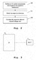
- Fig. 1 shows a flow chart of an embodiment of the inventive method for determining adjacent channel leakage ratio on the basis of a measurement limited to a certain bandwidth.
- a first step 100 an ideal output signal with respect to a device under test is determine on the basis of a reference signal provided to the device under test.
- a model of non-linearities is determined on the basis of a comparison between the ideal output signal and a measured output signal with respect to the device under test.
- the adjacent channel leakage ratio is determined on the basis of an out-of-band signal behavior created by applying the model.
- the reference signal may especially comprise or be a known signal, preferably a known signal into the respective amplifier.
- the certain bandwidth may especially comprise or be the bandwidth of the respective fundamental. In addition to this or as an alternative, the certain bandwidth may comprise or be less than three-times the respective carrier bandwidth.
- the method comprises the step of determining the reference signal on the basis of a demodulation of the respective fundamental.
- the method comprises the step of measuring over time in order to eliminate the respective noise via averaging, preferably I/Q averaging.
- the method may especially comprise the step of equalizing in order to eliminate the respective frequency response.
- the model may especially comprise or be a mathematical model. Additionally or alternatively, with respect to the non-linearities, the non-linearities may especially comprise or be distortions. In further addition to this or as a further alternative, also with respect to the model, the model, preferably the mathematical model, may especially comprise or be a polynomial model. In this context, the polynomial model may especially model the respective coefficients.
- the method may especially comprise the step of determining the respective third order coefficient and/or the respective fifth order coefficient. Additionally or alternatively, also with respect to the polynomial model, the method may especially comprise the step of determining the respective second order coefficient and/or the respective fourth order coefficient.
- the non-linearities may especially comprise or be memory effects distortions.
- the method may especially comprise the step of determining the memory effects distortions on the basis of the Volterra model, a memory polynomial model, a generalized memory polynomial model, or any combination thereof.
- the non-linearities may comprise or be time non-linearities.
- the method may especially comprise the step of determining the time non-linearities on the basis of iterations configured to find a respective pre-distortion eliminating the time non-linearities.
- said time non-linearities may especially comprise or be memory effects, preferably the memory effects distortions.
- Fig. 2 illustrates a flow chart of a further embodiment of the inventive method for determining adjacent channel leakage ratio on the basis of a measurement limited to a certain bandwidth.
- this second embodiment of the inventive method can at least partly be seen as an addition or as an alternative to the first embodiment according to Fig. 1 . Accordingly, these two embodiments could also be combined especially in order to form further embodiments of the inventive method. It is further noted that these combinations or further embodiments (including the first and the second embodiment according to Fig. 1 and Fig. 2 ), respectively, do analogously apply for the inventive device such as the exemplary embodiment thereof according to Fig. 3 .
- a first step 200 an IQ (In-phase Quadrature-phase) capture measurement is performed with respect to the respective fundamental.
- the respective distortion is modelled.
- the respective adjacent channel leakage ratio is calculated.
- the respective fundamental may especially comprise at least one higher order distortion such as third and/or fifth order distortions.
- the respective distortion may especially be modelled by a polynomial algorithm such as the polynomial model according to the first embodiment of Fig. 1 .
- another algorithm such as an iteration may be used.
- the respective error vector magnitude may be calculated. It is further noted that the calculation of the respective adjacent channel leakage ration and/or the respective error vector magnitude may preferably be based on the model, especially the model of the respective distortion, and/or on at least one, especially one, set of IQ data.
- the invention provides the benefit that only one, especially only one narrow band, capture is necessary, which saves not only time but also costs. Further advantageously, especially with respect to a device for determining the adjacent channel leakage ratio, there is no need to switch between a swept spectrum and an IQ mode. Furthermore, the invention especially allows for no stitching of several captures. As a further benefit, it is noted that especially in accordance with the invention, one capture is sufficient not only for adjacent channel leakage ratio but also for error magnitude vector measurements.
- FIG. 3 a block diagram of an exemplary embodiment of the inventive device 10 for determining adjacent channel leakage ratio on the basis of a measurement limited to a certain bandwidth is shown.
- the device 10 is configured to determine an ideal output signal with respect to a device under test 11 on the basis of a reference signal provided to the device under test 11.
- the device 10 is further configured to determine a model of non-linearities on the basis of a comparison between the ideal output signal and a measured output signal with respect to the device under test 11.
- the device 10 is configured to determine the adjacent channel leakage ratio on the basis of an out-of-band signal behavior created by applying the model.
- the device 10 comprises or is a signal analyzer comprising a signal analysis bandwidth.
- the certain bandwidth may especially comprise or be the bandwidth of the respective fundamental. Further additionally or further alternatively, the certain bandwidth may especially comprise or be less than three-times the respective carrier bandwidth.
- the device 10 may alternatively comprise or be a spectrum analyzer.
- the device 10 may especially be configured to determine the reference signal on the basis of a demodulation of the respective fundamental.
- the signal analysis bandwidth may comprise or be the certain bandwidth. Accordingly, the signal analysis bandwidth may preferably be less than three-times the respective carrier bandwidth.
- the device 10 may especially be configured to measure over time in order to eliminate the respective noise via averaging, preferably I/Q averaging.
- the device 10 may especially be configured to equalize in order to eliminate the respective frequency response.
- the model may especially comprise or be a mathematical model. Additionally or alternatively, with respect to the non-linearities, it is noted that the non-linearities may especially comprise or be distortions. In further addition to this or as a further alternative, the model, preferably the mathematical model, may especially comprise or be a polynomial model.
- the device 10 may especially be configured to determine the respective third order coefficient and/or the respective fifth order coefficient.
- the device 10 may especially be configured to determine the respective second order coefficient and/or the respective fourth order coefficient.
- the non-linearities may especially comprise or be memory effects distortions.
- the device 10 may especially be configured to determine the memory effects distortions on the basis of the Volterra model, a memory polynomial model, a generalized memory polynomial model, or any combination thereof.
- the non-linearities may especially comprise or be time non-linearities.
- the device 10 may especially be configured to determine the time non-linearities such as memory effects, preferably the memory effects distortions, on the basis of iterations configured to find a respective pre-distortion eliminating the time non-linearities.
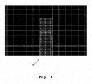
- Fig. 4 an exemplary signal 30 is shown. As it can be seen, said signal 30 is a perfect or ideal signal. Accordingly, there are no non-linearities and there is no adjacent channel leakage.
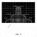
- Fig. 5 illustrates an exemplary imperfect or real signal 31.
- non-linearities especially cause spectral regrowth.
- the respective fundamental signal is especially underlaid with higher order distortions.
- the fundamental signal is exemplarily underlaid with a third and a fifth order distortion.
- an IQ capturing of the fundamental would especially capture also a part of the higher order distortions, exemplarily the third and the fifth order distortions.
- Fig. 6 shows the real signal 31 with non-linearities according to Fig. 5 again.
- the respective transmitting channel (Tx) and adjacent channels exemplarily two adjacent channels (Adj 1 and Adj 2), are marked.
- Fig. 7 shows the imperfect or real signal 31 with non-linearities according to Fig. 5 or Fig. 6 , respectively, again.
- the respective analysis bandwidth 32 is marked.
- the analysis bandwidth 32 is especially equal to the bandwidth of the respective fundamental.
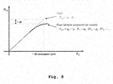
- Fig. 8 shows the output power as a function of the respective input power with respect to an ideal signal such as the signal 30 of Fig. 4 and with respect to a real signal such as the signal 31 according to Fig. 5 .
- Fig. 9 illustrates a further exemplary embodiment of a polynomial model.
- equation (2) is exemplarily applied to a two-tone signal comprising the frequencies f 1 and f 2 .
- second and third order distortions are exemplarily depicted.
Landscapes
- Physics & Mathematics (AREA)
- Nonlinear Science (AREA)
- Mathematical Physics (AREA)
- General Physics & Mathematics (AREA)
- Digital Transmission Methods That Use Modulated Carrier Waves (AREA)
Abstract
Description
- The invention relates to a method for determining adjacent channel leakage ratio on the basis of a measurement limited to a certain bandwidth and a device and computer program for determining adjacent channel leakage ratio on the basis of a measurement limited to a certain bandwidth.
- Generally, in times of an increasing number of communication applications providing wireless connectivity capabilities, there is a growing need of a method for determining adjacent channel leakage ratio on the basis of a measurement limited to a certain bandwidth and a device for determining adjacent channel leakage ratio on the basis of a measurement limited to a certain bandwidth for performing measurements with respect to such applications in order to verify their correct functioning.
-
EP 1 688 751 A1 - Accordingly, there is an object to provide a method for determining adjacent channel leakage ratio on the basis of a measurement limited to a certain bandwidth and a device for determining adjacent channel leakage ratio on the basis of a measurement limited to a certain bandwidth, whereby a particularly high efficiency and accuracy of the measurement are ensured.
- This object is solved by the features of the first independent claim for a method for determining adjacent channel leakage ratio on the basis of a measurement limited to a certain bandwidth and the features of the second independent claim for a device for determining adjacent channel leakage ratio on the basis of a measurement limited to a certain bandwidth. The dependent claims contain further developments.
- According to a first aspect of the invention, a method for determining information, especially adjacent channel leakage ratio, on the basis of a measurement limited to a certain bandwidth is provided. Said method comprises the steps of determining an ideal output signal with respect to a device under test on the basis of a reference signal provided to the device under test, determining a model of non-linearities on the basis of a comparison between the ideal output signal and a measured output signal with respect to the device under test, and determining the adjacent channel leakage ratio on the basis of an out-of-band signal behavior created by applying the model. Advantageously, a single capture is sufficient for determining the adjacent channel leakage ratio, which saves time and therefore leads to a particularly high efficiency, thereby also ensuring a notably high accuracy.
- According to a first preferred implementation form of the first aspect of the invention, the certain bandwidth comprises or is the bandwidth of the respective fundamental. In addition to this or as an alternative, the certain bandwidth comprises or is less than three-times the respective carrier bandwidth. Advantageously, for instance, costs can be reduced due to a narrow analysis bandwidth especially leading to less expensive hardware.
- According to a second preferred implementation form of the first aspect of the invention, with respect to the reference signal, the method comprises the step of determining the reference signal on the basis of a demodulation of the respective fundamental. Advantageously, for example, complexity can be reduced, which leads to an increased efficiency.
- According to a further preferred implementation form of the first aspect of the invention, with respect to the measured output signal, the method comprises the step of measuring over time in order to eliminate the respective noise via averaging, preferably I/Q averaging. Advantageously, for instance, accuracy can be increased in an efficient manner.
- Further advantageously, said I/Q averaging is especially configured to average real and imaginary components of the respective complex baseband signal separately.
- According to a further preferred implementation form of the first aspect of the invention, with respect to the measured output signal, the method comprises the step of equalizing in order to eliminate the respective frequency response. Advantageously, for example, inaccuracies can further be reduced.
- According to a further preferred implementation form of the first aspect of the invention, the model comprises or is a mathematical model. In addition to this or as an alternative, the non-linearities comprise or are distortions. Advantageously, for instance, not only efficiency but also accuracy can be increased.
- According to a further preferred implementation form of the first aspect of the invention, the model comprises or is a polynomial model. Advantageously, for example, complexity can be reduced, which leads to an increased efficiency.
- According to a further preferred implementation form of the first aspect of the invention, with respect to the polynomial model, the method comprises the step of determining the respective third order coefficient and/or the respective fifth order coefficient. Advantageously, for instance, using just a part of the coefficients can further increase efficiency.
- According to a further preferred implementation form of the first aspect of the invention, with respect to the polynomial model, the method comprises the step of determining the respective second order coefficient and/or the respective fourth order coefficient. Advantageously, for example, measurement time can be shortened by using just a part of the coefficients.
- According to a further preferred implementation form of the first aspect of the invention, the non-linearities comprise or are memory effects distortions. In this context, with respect to the memory effects distortions, the method comprises the step of determining the memory effects distortions especially on the basis of the Volterra model, a memory polynomial model, a generalized memory polynomial model, or any combination thereof.. Advantageously, for instance, both efficiency and accuracy can further be increased. Further advantageously, with respect to the Volterra model, the memory polynomial model, the generalized memory polynomial model, or any combination thereof, respectively, it is noted that any mathematical model comprising and/or considering memory effects can be used.
- According to a further preferred implementation form of the first aspect of the invention, the non-linearities comprise or are time non-linearities. In this context, with respect to the time non-linearities, the method comprises the step of determining the time non-linearities on the basis of iterations configured to find a respective pre-distortion eliminating the time non-linearities. Advantageously, for example, inaccuracies can be reduced in a particularly efficient manner.
- According to a second aspect of the invention, a device for determining information, especially adjacent channel leakage ratio, on the basis of a measurement limited to a certain bandwidth is provided. Said device is configured to determine an ideal output signal with respect to a device under test on the basis of a reference signal provided to the device under test. The device is further configured to determine a model of non-linearities on the basis of a comparison between the ideal output signal and a measured output signal with respect to the device under test. In addition to this, the device is configured to determine the adjacent channel leakage ratio on the basis of an out-of-band signal behavior created by applying the model. Advantageously, a single capture is sufficient for determining the adjacent channel leakage ratio, which saves time and therefore leads to a particularly high efficiency, thereby also ensuring a notably high accuracy.
- According to a first preferred implementation form of the second aspect of the invention, the device comprises or is a signal analyzer comprising a signal analysis bandwidth. In addition to this or as an alternative, the certain bandwidth comprises or is the bandwidth of the respective fundamental. Further additionally or further alternatively, the certain bandwidth comprises or is less than three-times the respective carrier bandwidth. Advantageously, for instance, costs can be reduced due to a narrow analysis bandwidth especially leading to less expensive hardware.
- According to a second preferred implementation form of the second aspect of the invention, with respect to the reference signal, the device is configured to determine the reference signal on the basis of a demodulation of the respective fundamental. In addition to this or as an alternative, in the case that the device comprises or is a signal analyzer, the signal analysis bandwidth comprises or is the certain bandwidth. Advantageously, for example, complexity can be reduced, which leads to an increased efficiency.
- According to a further preferred implementation form of the second aspect of the invention, with respect to the measured output signal, the device is configured to measure over time in order to eliminate the respective noise via averaging, preferably I/Q averaging. Advantageously, for instance, accuracy can be increased in an efficient manner. Further advantageously, said I/Q averaging is especially configured to average real and imaginary components of the respective complex baseband signal separately.
- Exemplary embodiments of the invention are now further explained with respect to the drawings by way of example only, and not for limitation. In the drawings:
- Fig. 1
- shows a flow chart of an embodiment of the first aspect of the invention;
- Fig. 2
- shows a flow chart of a further embodiment of the inventive method;
- Fig. 3
- shows an exemplary embodiment of an inventive device;
- Fig. 4
- shows an exemplary perfect or ideal signal without non-linearities;
- Fig. 5
- shows an exemplary imperfect or real signal with non-linearities;
- Fig. 6
- shows the signal according to
Fig. 5 with marked transmitting channel and adjacent channels; - Fig. 7
- shows the signal according to
Fig. 5 with marked analysis bandwidth; - Fig. 8
- shows an exemplary embodiment of a polynomial model; and
- Fig. 9
- shows a further exemplary embodiment of a polynomial model.
-
Fig. 1 shows a flow chart of an embodiment of the inventive method for determining adjacent channel leakage ratio on the basis of a measurement limited to a certain bandwidth. In afirst step 100, an ideal output signal with respect to a device under test is determine on the basis of a reference signal provided to the device under test. Then, in asecond step 101, a model of non-linearities is determined on the basis of a comparison between the ideal output signal and a measured output signal with respect to the device under test. Furthermore, in athird step 102, the adjacent channel leakage ratio is determined on the basis of an out-of-band signal behavior created by applying the model. - With respect to the reference signal, it is noted that the reference signal may especially comprise or be a known signal, preferably a known signal into the respective amplifier. With respect to the certain bandwidth, it is noted that the certain bandwidth may especially comprise or be the bandwidth of the respective fundamental. In addition to this or as an alternative, the certain bandwidth may comprise or be less than three-times the respective carrier bandwidth.
- Again, with respect to the reference signal, it might be particularly advantageous if the method comprises the step of determining the reference signal on the basis of a demodulation of the respective fundamental. With respect to the measured output signal, it might be particularly advantageous if the method comprises the step of measuring over time in order to eliminate the respective noise via averaging, preferably I/Q averaging. In addition to this or as an alternative, also with respect to the measured output signal, the method may especially comprise the step of equalizing in order to eliminate the respective frequency response.
- With respect to the model, it is noted that the model may especially comprise or be a mathematical model. Additionally or alternatively, with respect to the non-linearities, the non-linearities may especially comprise or be distortions. In further addition to this or as a further alternative, also with respect to the model, the model, preferably the mathematical model, may especially comprise or be a polynomial model. In this context, the polynomial model may especially model the respective coefficients.
- Furthermore, with respect to the polynomial model, the method may especially comprise the step of determining the respective third order coefficient and/or the respective fifth order coefficient. Additionally or alternatively, also with respect to the polynomial model, the method may especially comprise the step of determining the respective second order coefficient and/or the respective fourth order coefficient.
- Again, with respect to the non-linearities, the non-linearities may especially comprise or be memory effects distortions. In this context, with respect to the memory effects distortions, the method may especially comprise the step of determining the memory effects distortions on the basis of the Volterra model, a memory polynomial model, a generalized memory polynomial model, or any combination thereof.
- In addition to this or as an alternative, the non-linearities may comprise or be time non-linearities. Furthermore, with respect to the time non-linearities, the method may especially comprise the step of determining the time non-linearities on the basis of iterations configured to find a respective pre-distortion eliminating the time non-linearities. For instance, said time non-linearities may especially comprise or be memory effects, preferably the memory effects distortions.
-
Fig. 2 illustrates a flow chart of a further embodiment of the inventive method for determining adjacent channel leakage ratio on the basis of a measurement limited to a certain bandwidth. In this context, it is noted that this second embodiment of the inventive method can at least partly be seen as an addition or as an alternative to the first embodiment according toFig. 1 . Accordingly, these two embodiments could also be combined especially in order to form further embodiments of the inventive method. It is further noted that these combinations or further embodiments (including the first and the second embodiment according toFig. 1 andFig. 2 ), respectively, do analogously apply for the inventive device such as the exemplary embodiment thereof according toFig. 3 . - As it can be seen from
Fig. 2 , in afirst step 200, an IQ (In-phase Quadrature-phase) capture measurement is performed with respect to the respective fundamental. According to asecond step 201, the respective distortion is modelled. Then, in athird step 202, the respective adjacent channel leakage ratio is calculated. With respect to thefirst step 200, it is noted that the respective fundamental may especially comprise at least one higher order distortion such as third and/or fifth order distortions. - In addition to this or as an alternative, with respect to the
second step 201, it is noted that the respective distortion may especially be modelled by a polynomial algorithm such as the polynomial model according to the first embodiment ofFig. 1 . In this context, as an alternative, another algorithm such as an iteration may be used. - Furthermore, with respect to the
third step 202, it is noted that in addition or as an alternative to the respective adjacent channel leakage ratio, the respective error vector magnitude may be calculated. It is further noted that the calculation of the respective adjacent channel leakage ration and/or the respective error vector magnitude may preferably be based on the model, especially the model of the respective distortion, and/or on at least one, especially one, set of IQ data. - It is generally noted that the invention provides the benefit that only one, especially only one narrow band, capture is necessary, which saves not only time but also costs. Further advantageously, especially with respect to a device for determining the adjacent channel leakage ratio, there is no need to switch between a swept spectrum and an IQ mode. Furthermore, the invention especially allows for no stitching of several captures. As a further benefit, it is noted that especially in accordance with the invention, one capture is sufficient not only for adjacent channel leakage ratio but also for error magnitude vector measurements.
- In
Fig. 3 , a block diagram of an exemplary embodiment of theinventive device 10 for determining adjacent channel leakage ratio on the basis of a measurement limited to a certain bandwidth is shown. - In this context, the
device 10 is configured to determine an ideal output signal with respect to a device undertest 11 on the basis of a reference signal provided to the device undertest 11. Thedevice 10 is further configured to determine a model of non-linearities on the basis of a comparison between the ideal output signal and a measured output signal with respect to the device undertest 11. In addition to this thedevice 10 is configured to determine the adjacent channel leakage ratio on the basis of an out-of-band signal behavior created by applying the model. - It is noted that it might be particularly advantageous if the
device 10 comprises or is a signal analyzer comprising a signal analysis bandwidth. In addition to this or as an alternative, the certain bandwidth may especially comprise or be the bandwidth of the respective fundamental. Further additionally or further alternatively, the certain bandwidth may especially comprise or be less than three-times the respective carrier bandwidth. In this context, especially with respect to the signal analyzer, thedevice 10 may alternatively comprise or be a spectrum analyzer. - Furthermore, with respect to the reference signal, the
device 10 may especially be configured to determine the reference signal on the basis of a demodulation of the respective fundamental. In addition to this or as an alternative, especially in the case that thedevice 10 comprises or is a signal analyzer or a spectrum analyzer, the signal analysis bandwidth may comprise or be the certain bandwidth. Accordingly, the signal analysis bandwidth may preferably be less than three-times the respective carrier bandwidth. - Moreover, with respect to the measured output signal, the
device 10 may especially be configured to measure over time in order to eliminate the respective noise via averaging, preferably I/Q averaging. In addition to this or as an alternative, also with respect to the measured output signal, thedevice 10 may especially be configured to equalize in order to eliminate the respective frequency response. - With respect to the model, it is noted that the model may especially comprise or be a mathematical model. Additionally or alternatively, with respect to the non-linearities, it is noted that the non-linearities may especially comprise or be distortions. In further addition to this or as a further alternative, the model, preferably the mathematical model, may especially comprise or be a polynomial model.
- In this context, with respect to the polynomial model, the
device 10 may especially be configured to determine the respective third order coefficient and/or the respective fifth order coefficient. In addition to this or as an alternative, also with respect to the polynomial model, thedevice 10 may especially be configured to determine the respective second order coefficient and/or the respective fourth order coefficient. - Again, with respect to the non-linearities, it is noted that the non-linearities may especially comprise or be memory effects distortions. In this context, with respect to the memory effects distortions, the
device 10 may especially be configured to determine the memory effects distortions on the basis of the Volterra model, a memory polynomial model, a generalized memory polynomial model, or any combination thereof. - Additionally or alternatively, also with respect to the non-linearities, it is noted that the non-linearities may especially comprise or be time non-linearities. In this context, with respect to the time non-linearities, the
device 10 may especially be configured to determine the time non-linearities such as memory effects, preferably the memory effects distortions, on the basis of iterations configured to find a respective pre-distortion eliminating the time non-linearities. - In
Fig. 4 , anexemplary signal 30 is shown. As it can be seen, saidsignal 30 is a perfect or ideal signal. Accordingly, there are no non-linearities and there is no adjacent channel leakage. - In contrast to
Fig. 4 ,Fig. 5 illustrates an exemplary imperfect orreal signal 31. In this context, non-linearities especially cause spectral regrowth. Accordingly, the respective fundamental signal is especially underlaid with higher order distortions. As it can be seen fromFig. 5 , the fundamental signal is exemplarily underlaid with a third and a fifth order distortion. For instance, it is noted that an IQ capturing of the fundamental would especially capture also a part of the higher order distortions, exemplarily the third and the fifth order distortions. -
Fig. 6 shows thereal signal 31 with non-linearities according toFig. 5 again. In this context, the respective transmitting channel (Tx) and adjacent channels, exemplarily two adjacent channels (Adj 1 and Adj 2), are marked. - Moreover,
Fig. 7 shows the imperfect orreal signal 31 with non-linearities according toFig. 5 orFig. 6 , respectively, again. As it can be seen fromFig. 7 , therespective analysis bandwidth 32 is marked. Exemplarily, theanalysis bandwidth 32 is especially equal to the bandwidth of the respective fundamental. - Now, with respect to
Fig. 8 , an exemplary embodiment of a polynomial model is illustrated. More specifically,Fig. 8 shows the output power as a function of the respective input power with respect to an ideal signal such as thesignal 30 ofFig. 4 and with respect to a real signal such as thesignal 31 according toFig. 5 . - In accordance with
Fig. 8 , for an ideal signal, the following equation applies:
- wherein Pout denotes the output power,
- wherein a 1 denotes a coefficient, and
- wherein Pin denotes the input power.
- Furthermore, for a real signal, especially in accordance with a simple polynomial model, the following equation applies:

- wherein, as already noted above, Pout denotes the output power,
- wherein a 0 , a1 , a2, a3, ... denote coefficients, especially polynomial coefficients, and
- wherein, as already noted above, Pin denotes the input power.
- As it can further be seen from
Fig. 8 , the respective 1 dB compression point with respect to the ideal and the real signal is marked. - Finally,
Fig. 9 illustrates a further exemplary embodiment of a polynomial model. In this context, the above-mentioned equation (2) is exemplarily applied to a two-tone signal comprising the frequencies f1 and f 2. Additionally, second and third order distortions are exemplarily depicted. - Accordingly, for the respective input power of said two-tone signal, the following applies:

- Now, the corresponding output power can be calculated especially in a simplified manner with the aid of equation (2) as follows:

- It is noted that the knowledge of the polynomial coefficients allows to derive the respective spectral regrowth.
- While various embodiments of the present invention have been described above, it should be understood that they have been presented by way of example only, and not limitation. Numerous changes to the disclosed embodiments can be made in accordance with the disclosure herein without departing from the spirit or scope of the invention. Thus, the breadth and scope of the present invention should not be limited by any of the above described embodiments. Rather, the scope of the invention should be defined in accordance with the following claims and their equivalents.
- Although the invention has been illustrated and described with respect to one or more implementations, equivalent alterations and modifications will occur to others skilled in the art upon the reading and understanding of this specification and the annexed drawings. In addition, while a particular feature of the invention may have been disclosed with respect to only one of several implementations, such feature may be combined with one or more other features of the other implementations as may be desired and advantageous for any given or particular application.
Claims (17)
- A method for determining adjacent channel information on the basis of a measurement limited to a certain bandwidth, the method comprising the steps of:determining an ideal output signal with respect to a device under test (11) on the basis of a reference signal provided to the device under test (11),determining a model of non-linearities on the basis of a comparison between the ideal output signal and a measured output signal with respect to the device under test (11), anddetermining the adjacent channel information on the basis of an out-of-band signal behavior created by applying the model.
- The method according to claim 1,
wherein the certain bandwidth comprises or is the bandwidth of the respective fundamental, and/or
wherein the certain bandwidth comprises or is less than three-times the respective carrier bandwidth. - The method according to claim 1 or 2,
wherein with respect to the reference signal, the method comprises the step of determining the reference signal on the basis of a demodulation of the respective fundamental. - The method according to any of the claims 1 to 3,
wherein with respect to the measured output signal, the method comprises the step of measuring over time in order to eliminate the respective noise via averaging, preferably I/Q averaging. - The method according to any of the claims 1 to 4,
wherein with respect to the measured output signal, the method comprises the step of equalizing in order to eliminate the respective frequency response. - The method according to any of the claims 1 to 5,
wherein the model comprises or is a mathematical model, and/or
wherein the non-linearities comprise or are distortions. - The method according to any of the claims 1 to 6,
wherein the model comprises or is a polynomial model and/or
wherein the adjacent channel information determined is an adjacent channel leakage ratio. - The method according to claim 7,
wherein with respect to the polynomial model, the method comprises the step of determining the respective third order coefficient and/or the respective fifth order coefficient. - The method according to claim 7 or 8,
wherein with respect to the polynomial model, the method comprises the step of determining the respective second order coefficient and/or the respective fourth order coefficient. - The method according to any of the claims 1 to 9,
wherein the non-linearities comprise or are memory effects distortions,
wherein with respect to the memory effects distortions, the method comprises the step of determining the memory effects distortions especially on the basis of the Volterra model, a memory polynomial model, a generalized memory polynomial model, or any combination thereof. - The method according to any of the claims 1 to 10,
wherein the non-linearities comprise or are time non-linearities,
wherein with respect to the time non-linearities, the method comprises the step of determining the time non-linearities on the basis of iterations configured to find a respective pre-distortion eliminating the time non-linearities. - A device (10) for determining adjacent channel information on the basis of a measurement limited to a certain bandwidth, the device (10) being configured to
determine an ideal output signal with respect to a device under test (11) on the basis of a reference signal provided to the device under test (11),
determine a model of non-linearities on the basis of a comparison between the ideal output signal and a measured output signal with respect to the device under test (11), and
determine the adjacent channel information on the basis of an out-of-band signal behavior created by applying the model. - The device (10) according to claim 12,
wherein the device (10) comprises or is a signal analyzer comprising a signal analysis bandwidth (32), and/or
wherein the certain bandwidth comprises or is the bandwidth of the respective fundamental, and/or
wherein the certain bandwidth comprises or is less than three-times the respective carrier bandwidth. - The device (10) according to claim 12 or 13,
wherein with respect to the reference signal, the device (10) is configured to determine the reference signal on the basis of a demodulation of the respective fundamental. - The device (10) according to claim 13,
wherein, the signal analysis bandwidth (32) comprises or is the certain bandwidth. - The device (10) according to any of the claims 12 to 15,
wherein with respect to the measured output signal, the device (10) is configured to measure over time in order to eliminate the respective noise via averaging, preferably I/Q averaging, and/or
wherein the adjacent channel information determined is an adjacent channel leakage ratio. - A computer program with computer program means for performing all steps of any of claims 1 to 11 if the computer program runs on a computer or digital signal processor.
Priority Applications (1)
| Application Number | Priority Date | Filing Date | Title |
|---|---|---|---|
| EP20182774.8A EP3933413A1 (en) | 2020-06-29 | 2020-06-29 | Method and device for determining adjacent channel leakage ratio on the basis of a bandwidth-limited measurement |
Applications Claiming Priority (1)
| Application Number | Priority Date | Filing Date | Title |
|---|---|---|---|
| EP20182774.8A EP3933413A1 (en) | 2020-06-29 | 2020-06-29 | Method and device for determining adjacent channel leakage ratio on the basis of a bandwidth-limited measurement |
Publications (1)
| Publication Number | Publication Date |
|---|---|
| EP3933413A1 true EP3933413A1 (en) | 2022-01-05 |
Family
ID=71266434
Family Applications (1)
| Application Number | Title | Priority Date | Filing Date |
|---|---|---|---|
| EP20182774.8A Withdrawn EP3933413A1 (en) | 2020-06-29 | 2020-06-29 | Method and device for determining adjacent channel leakage ratio on the basis of a bandwidth-limited measurement |
Country Status (1)
| Country | Link |
|---|---|
| EP (1) | EP3933413A1 (en) |
Citations (7)
| Publication number | Priority date | Publication date | Assignee | Title |
|---|---|---|---|---|
| JPH11154880A (en) * | 1997-09-05 | 1999-06-08 | Fujitsu Ltd | Signal correction method and device, distortion compensation device, distortion compensation data creation device, and transmitter |
| US20040098215A1 (en) * | 2002-11-19 | 2004-05-20 | Kevin Gee | Method for the rapid estimation of figures of merit for multiple devices based on nonlinear modeling |
| EP1688751A1 (en) | 2005-02-07 | 2006-08-09 | Tektronix, Inc. | Time correlation of signal power to distortion characteristics |
| US20090058521A1 (en) * | 2007-08-31 | 2009-03-05 | Fernandez Andrew D | System and method of digital linearization in electronic devices |
| KR101195977B1 (en) * | 2010-11-17 | 2012-10-30 | 서강대학교산학협력단 | Apparatus and method for behavioral modeling of the power amplifier |
| US10379162B1 (en) * | 2017-10-31 | 2019-08-13 | Keysight Technologies, Inc. | System for performing modulation analysis without using a modulated signal |
| US20200021253A1 (en) * | 2017-02-15 | 2020-01-16 | Fadhel Ghannouchi | System and method for rf amplifiers |
-
2020
- 2020-06-29 EP EP20182774.8A patent/EP3933413A1/en not_active Withdrawn
Patent Citations (7)
| Publication number | Priority date | Publication date | Assignee | Title |
|---|---|---|---|---|
| JPH11154880A (en) * | 1997-09-05 | 1999-06-08 | Fujitsu Ltd | Signal correction method and device, distortion compensation device, distortion compensation data creation device, and transmitter |
| US20040098215A1 (en) * | 2002-11-19 | 2004-05-20 | Kevin Gee | Method for the rapid estimation of figures of merit for multiple devices based on nonlinear modeling |
| EP1688751A1 (en) | 2005-02-07 | 2006-08-09 | Tektronix, Inc. | Time correlation of signal power to distortion characteristics |
| US20090058521A1 (en) * | 2007-08-31 | 2009-03-05 | Fernandez Andrew D | System and method of digital linearization in electronic devices |
| KR101195977B1 (en) * | 2010-11-17 | 2012-10-30 | 서강대학교산학협력단 | Apparatus and method for behavioral modeling of the power amplifier |
| US20200021253A1 (en) * | 2017-02-15 | 2020-01-16 | Fadhel Ghannouchi | System and method for rf amplifiers |
| US10379162B1 (en) * | 2017-10-31 | 2019-08-13 | Keysight Technologies, Inc. | System for performing modulation analysis without using a modulated signal |
Non-Patent Citations (2)
| Title |
|---|
| GARD K G ET AL: "The Impact of RF Front-End Characteristics on the Spectral Regrowth of Communications Signals", IEEE TRANSACTIONS ON MICROWAVE THEORY AND TECHNIQUES, PLENUM, USA, vol. 53, no. 6, 1 June 2005 (2005-06-01), pages 2179 - 2186, XP011134729, ISSN: 0018-9480, DOI: 10.1109/TMTT.2005.848801 * |
| HAMMI OUALID ET AL: "Agile broadband behavioral modelling of nonlinear power amplifiers using coarse-predistortion technique", 2018 INTERNATIONAL CONFERENCE ON SIGNALS AND SYSTEMS (ICSIGSYS), IEEE, 1 May 2018 (2018-05-01), pages 7 - 12, XP033354371, DOI: 10.1109/ICSIGSYS.2018.8373571 * |
Similar Documents
| Publication | Publication Date | Title |
|---|---|---|
| US7822130B2 (en) | Apparatus and method for simultaneous testing of multiple orthogonal frequency division multiplexed transmitters with single vector signal analyzer | |
| Gharaibeh et al. | Accurate estimation of digital communication system metrics-SNR, EVM and/spl rho/in a nonlinear amplifier environment | |
| US7652532B2 (en) | Correlation method for monitoring power amplifier | |
| EP0847153A2 (en) | Method and apparatus for measuring waveform quality of CDMA signal | |
| EP1152563B1 (en) | Method for displaying signal quality measurement | |
| CN114563769B (en) | Method and device for measuring phase nonlinearity of digital phased array receiving channel | |
| US10379162B1 (en) | System for performing modulation analysis without using a modulated signal | |
| US20040098215A1 (en) | Method for the rapid estimation of figures of merit for multiple devices based on nonlinear modeling | |
| US8358169B2 (en) | Systems and methods for distortion measurement using distortion-to-amplitude transformations | |
| US12452111B2 (en) | Method, apparatus and communication system for evaluating nonlinear compensation performance | |
| US12480991B2 (en) | Electronic device for improving a performance of a signal chain | |
| Sombrin | On the formal identity of EVM and NPR measurement methods: Conditions for identity of error vector magnitude and noise power ratio | |
| US20230266370A1 (en) | Method, apparatus and system for measuring nonlinear related parameters of nonlinear device | |
| US10057020B2 (en) | Joint estimation of coefficients for skew, gain imbalance and channel response for signal sources | |
| US11496166B1 (en) | Predistortion method and system for a non-linear device-under-test | |
| US10476549B1 (en) | Transmitter linearity built-in-self-test | |
| US6657492B1 (en) | System for estimating a non-linear characteristic of an amplifier | |
| CN112130011B (en) | A kind of EVM test method for spaceborne power amplifier | |
| CN101268643B (en) | Apparatus and method for simultaneously testing multiple OFDM transmitters using a single vector signal analyzer | |
| Rodriguez-Avila et al. | A frequency-selective I/Q imbalance analysis technique | |
| US10243678B2 (en) | Linearization of radio frequency transceivers and test systems through dynamic extraction of complex nonlinear models thereof | |
| Santos et al. | EVM estimation in RF/wireless components | |
| Fu et al. | Test bed for power amplifier behavioral characterization and modeling | |
| US7720137B2 (en) | Characterization of a frequency response for a frequency translation device | |
| Silva et al. | Survey of characterization techniques for nonlinear communication components and systems |
Legal Events
| Date | Code | Title | Description |
|---|---|---|---|
| PUAI | Public reference made under article 153(3) epc to a published international application that has entered the european phase |
Free format text: ORIGINAL CODE: 0009012 |
|
| STAA | Information on the status of an ep patent application or granted ep patent |
Free format text: STATUS: REQUEST FOR EXAMINATION WAS MADE |
|
| 17P | Request for examination filed |
Effective date: 20210427 |
|
| AK | Designated contracting states |
Kind code of ref document: A1 Designated state(s): AL AT BE BG CH CY CZ DE DK EE ES FI FR GB GR HR HU IE IS IT LI LT LU LV MC MK MT NL NO PL PT RO RS SE SI SK SM TR |
|
| B565 | Issuance of search results under rule 164(2) epc |
Effective date: 20210114 |
|
| STAA | Information on the status of an ep patent application or granted ep patent |
Free format text: STATUS: EXAMINATION IS IN PROGRESS |
|
| 17Q | First examination report despatched |
Effective date: 20221223 |
|
| P01 | Opt-out of the competence of the unified patent court (upc) registered |
Effective date: 20230525 |
|
| STAA | Information on the status of an ep patent application or granted ep patent |
Free format text: STATUS: THE APPLICATION IS DEEMED TO BE WITHDRAWN |
|
| 18D | Application deemed to be withdrawn |
Effective date: 20250322 |