EP3933378A1 - Particle separating and measuring device, and particle separating and measuring apparatus - Google Patents
Particle separating and measuring device, and particle separating and measuring apparatus Download PDFInfo
- Publication number
- EP3933378A1 EP3933378A1 EP20762604.5A EP20762604A EP3933378A1 EP 3933378 A1 EP3933378 A1 EP 3933378A1 EP 20762604 A EP20762604 A EP 20762604A EP 3933378 A1 EP3933378 A1 EP 3933378A1
- Authority
- EP
- European Patent Office
- Prior art keywords
- flow path
- flow
- inlet
- opening
- separation
- Prior art date
- Legal status (The legal status is an assumption and is not a legal conclusion. Google has not performed a legal analysis and makes no representation as to the accuracy of the status listed.)
- Withdrawn
Links
Images






Classifications
-
- B—PERFORMING OPERATIONS; TRANSPORTING
- B01—PHYSICAL OR CHEMICAL PROCESSES OR APPARATUS IN GENERAL
- B01L—CHEMICAL OR PHYSICAL LABORATORY APPARATUS FOR GENERAL USE
- B01L3/00—Containers or dishes for laboratory use, e.g. laboratory glassware; Droppers
- B01L3/50—Containers for the purpose of retaining a material to be analysed, e.g. test tubes
- B01L3/502—Containers for the purpose of retaining a material to be analysed, e.g. test tubes with fluid transport, e.g. in multi-compartment structures
- B01L3/5027—Containers for the purpose of retaining a material to be analysed, e.g. test tubes with fluid transport, e.g. in multi-compartment structures by integrated microfluidic structures, i.e. dimensions of channels and chambers are such that surface tension forces are important, e.g. lab-on-a-chip
- B01L3/502761—Containers for the purpose of retaining a material to be analysed, e.g. test tubes with fluid transport, e.g. in multi-compartment structures by integrated microfluidic structures, i.e. dimensions of channels and chambers are such that surface tension forces are important, e.g. lab-on-a-chip specially adapted for handling suspended solids or molecules independently from the bulk fluid flow, e.g. for trapping or sorting beads or physically stretching molecules
-
- G—PHYSICS
- G01—MEASURING; TESTING
- G01N—INVESTIGATING OR ANALYSING MATERIALS BY DETERMINING THEIR CHEMICAL OR PHYSICAL PROPERTIES
- G01N15/00—Investigating characteristics of particles; Investigating permeability, pore-volume or surface-area of porous materials
- G01N15/10—Investigating individual particles
- G01N15/1023—Microstructural devices for non-optical measurement
-
- G—PHYSICS
- G01—MEASURING; TESTING
- G01N—INVESTIGATING OR ANALYSING MATERIALS BY DETERMINING THEIR CHEMICAL OR PHYSICAL PROPERTIES
- G01N15/00—Investigating characteristics of particles; Investigating permeability, pore-volume or surface-area of porous materials
- G01N15/02—Investigating particle size or size distribution
- G01N15/0255—Investigating particle size or size distribution with mechanical, e.g. inertial, classification, and investigation of sorted collections
-
- G—PHYSICS
- G01—MEASURING; TESTING
- G01N—INVESTIGATING OR ANALYSING MATERIALS BY DETERMINING THEIR CHEMICAL OR PHYSICAL PROPERTIES
- G01N15/00—Investigating characteristics of particles; Investigating permeability, pore-volume or surface-area of porous materials
- G01N15/10—Investigating individual particles
- G01N15/14—Optical investigation techniques, e.g. flow cytometry
- G01N15/1456—Optical investigation techniques, e.g. flow cytometry without spatial resolution of the texture or inner structure of the particle, e.g. processing of pulse signals
- G01N15/1459—Optical investigation techniques, e.g. flow cytometry without spatial resolution of the texture or inner structure of the particle, e.g. processing of pulse signals the analysis being performed on a sample stream
-
- G—PHYSICS
- G01—MEASURING; TESTING
- G01N—INVESTIGATING OR ANALYSING MATERIALS BY DETERMINING THEIR CHEMICAL OR PHYSICAL PROPERTIES
- G01N37/00—Details not covered by any other group of this subclass
-
- B—PERFORMING OPERATIONS; TRANSPORTING
- B01—PHYSICAL OR CHEMICAL PROCESSES OR APPARATUS IN GENERAL
- B01L—CHEMICAL OR PHYSICAL LABORATORY APPARATUS FOR GENERAL USE
- B01L2200/00—Solutions for specific problems relating to chemical or physical laboratory apparatus
- B01L2200/06—Fluid handling related problems
- B01L2200/0636—Focussing flows, e.g. to laminate flows
-
- B—PERFORMING OPERATIONS; TRANSPORTING
- B01—PHYSICAL OR CHEMICAL PROCESSES OR APPARATUS IN GENERAL
- B01L—CHEMICAL OR PHYSICAL LABORATORY APPARATUS FOR GENERAL USE
- B01L2200/00—Solutions for specific problems relating to chemical or physical laboratory apparatus
- B01L2200/06—Fluid handling related problems
- B01L2200/0647—Handling flowable solids, e.g. microscopic beads, cells, particles
- B01L2200/0652—Sorting or classification of particles or molecules
-
- B—PERFORMING OPERATIONS; TRANSPORTING
- B01—PHYSICAL OR CHEMICAL PROCESSES OR APPARATUS IN GENERAL
- B01L—CHEMICAL OR PHYSICAL LABORATORY APPARATUS FOR GENERAL USE
- B01L2300/00—Additional constructional details
- B01L2300/06—Auxiliary integrated devices, integrated components
- B01L2300/0681—Filter
-
- B—PERFORMING OPERATIONS; TRANSPORTING
- B01—PHYSICAL OR CHEMICAL PROCESSES OR APPARATUS IN GENERAL
- B01L—CHEMICAL OR PHYSICAL LABORATORY APPARATUS FOR GENERAL USE
- B01L2300/00—Additional constructional details
- B01L2300/08—Geometry, shape and general structure
- B01L2300/0809—Geometry, shape and general structure rectangular shaped
- B01L2300/0816—Cards, e.g. flat sample carriers usually with flow in two horizontal directions
-
- B—PERFORMING OPERATIONS; TRANSPORTING
- B01—PHYSICAL OR CHEMICAL PROCESSES OR APPARATUS IN GENERAL
- B01L—CHEMICAL OR PHYSICAL LABORATORY APPARATUS FOR GENERAL USE
- B01L2300/00—Additional constructional details
- B01L2300/08—Geometry, shape and general structure
- B01L2300/0887—Laminated structure
-
- B—PERFORMING OPERATIONS; TRANSPORTING
- B01—PHYSICAL OR CHEMICAL PROCESSES OR APPARATUS IN GENERAL
- B01L—CHEMICAL OR PHYSICAL LABORATORY APPARATUS FOR GENERAL USE
- B01L2300/00—Additional constructional details
- B01L2300/16—Surface properties and coatings
- B01L2300/168—Specific optical properties, e.g. reflective coatings
-
- G—PHYSICS
- G01—MEASURING; TESTING
- G01N—INVESTIGATING OR ANALYSING MATERIALS BY DETERMINING THEIR CHEMICAL OR PHYSICAL PROPERTIES
- G01N15/00—Investigating characteristics of particles; Investigating permeability, pore-volume or surface-area of porous materials
- G01N15/10—Investigating individual particles
- G01N15/14—Optical investigation techniques, e.g. flow cytometry
- G01N15/1484—Optical investigation techniques, e.g. flow cytometry microstructural devices
-
- G—PHYSICS
- G01—MEASURING; TESTING
- G01N—INVESTIGATING OR ANALYSING MATERIALS BY DETERMINING THEIR CHEMICAL OR PHYSICAL PROPERTIES
- G01N15/00—Investigating characteristics of particles; Investigating permeability, pore-volume or surface-area of porous materials
- G01N15/10—Investigating individual particles
- G01N15/14—Optical investigation techniques, e.g. flow cytometry
- G01N15/149—Optical investigation techniques, e.g. flow cytometry specially adapted for sorting particles, e.g. by their size or optical properties
-
- G—PHYSICS
- G01—MEASURING; TESTING
- G01N—INVESTIGATING OR ANALYSING MATERIALS BY DETERMINING THEIR CHEMICAL OR PHYSICAL PROPERTIES
- G01N15/00—Investigating characteristics of particles; Investigating permeability, pore-volume or surface-area of porous materials
- G01N15/01—Investigating characteristics of particles; Investigating permeability, pore-volume or surface-area of porous materials specially adapted for biological cells, e.g. blood cells
- G01N2015/012—Red blood cells
-
- G—PHYSICS
- G01—MEASURING; TESTING
- G01N—INVESTIGATING OR ANALYSING MATERIALS BY DETERMINING THEIR CHEMICAL OR PHYSICAL PROPERTIES
- G01N15/00—Investigating characteristics of particles; Investigating permeability, pore-volume or surface-area of porous materials
- G01N15/01—Investigating characteristics of particles; Investigating permeability, pore-volume or surface-area of porous materials specially adapted for biological cells, e.g. blood cells
- G01N2015/016—White blood cells
-
- G—PHYSICS
- G01—MEASURING; TESTING
- G01N—INVESTIGATING OR ANALYSING MATERIALS BY DETERMINING THEIR CHEMICAL OR PHYSICAL PROPERTIES
- G01N15/00—Investigating characteristics of particles; Investigating permeability, pore-volume or surface-area of porous materials
- G01N15/10—Investigating individual particles
- G01N2015/1006—Investigating individual particles for cytology
-
- G—PHYSICS
- G01—MEASURING; TESTING
- G01N—INVESTIGATING OR ANALYSING MATERIALS BY DETERMINING THEIR CHEMICAL OR PHYSICAL PROPERTIES
- G01N15/00—Investigating characteristics of particles; Investigating permeability, pore-volume or surface-area of porous materials
- G01N15/10—Investigating individual particles
- G01N2015/1028—Sorting particles
-
- G—PHYSICS
- G01—MEASURING; TESTING
- G01N—INVESTIGATING OR ANALYSING MATERIALS BY DETERMINING THEIR CHEMICAL OR PHYSICAL PROPERTIES
- G01N15/00—Investigating characteristics of particles; Investigating permeability, pore-volume or surface-area of porous materials
- G01N15/10—Investigating individual particles
- G01N15/14—Optical investigation techniques, e.g. flow cytometry
- G01N2015/1486—Counting the particles
-
- G—PHYSICS
- G01—MEASURING; TESTING
- G01N—INVESTIGATING OR ANALYSING MATERIALS BY DETERMINING THEIR CHEMICAL OR PHYSICAL PROPERTIES
- G01N15/00—Investigating characteristics of particles; Investigating permeability, pore-volume or surface-area of porous materials
- G01N15/10—Investigating individual particles
- G01N15/14—Optical investigation techniques, e.g. flow cytometry
- G01N2015/1493—Particle size
Definitions
- the present disclosure relates to a particle separating and measuring device and a particle separating and measuring apparatus used to separate and measure specific particles from multiple types of particles contained in a liquid.
- a known particle separating device separates and extracts particles from a liquid using a microfluidic structure (micro flow paths) several to several hundred micrometers wide and having a flow inlet and multiple flow outlets (refer to, for example, Japanese Patent Application Laid-Open No. 2012-76016 ).
- a particle separating device receives a liquid (e.g., blood) containing, for example, multiple types of particles (e.g., erythrocytes and leukocytes) through the flow inlet, separates target particles (e.g., leukocytes) from the liquid, and individually extracts the target particles and the other particles through the multiple flow outlets.
- a liquid e.g., blood
- target particles e.g., leukocytes
- the separated and extracted target particles are then measured for, for example, their type, number, density, or optical properties.
- a particle separating and measuring device includes a first flow path device that is plate-like, and including a pre-separation flow inlet to receive a fluid containing target particles to be separated, a main flow path connected to the pre-separation flow inlet, a plurality of branch flow paths connected to the main flow path, and a post-separation flow outlet to discharge a first fluid containing the target particles after being separated, and a second flow path device that is plate-like, and including a first region receiving the first flow path device, a second region defining a region to allow measurement of the target particles, a first flow inlet to receive the first fluid, a second flow inlet to receive a second fluid free from the target particles, a first flow path located in the second region and connected to the first flow inlet to allow a flow of the first fluid, and a second flow path located in the second region and connected to the second flow inlet to allow a flow of the second fluid.
- the first flow path device having a lower surface having the post-separation flow outlet is on the second flow path device having an upper surface having the first flow inlet in the first region, with the post-separation flow outlet facing and connecting to the first flow inlet.
- the post-separation flow outlet and the first flow inlet each have a circular opening.
- the first flow inlet has the opening larger than the opening of the post-separation flow outlet.
- the post-separation flow outlet has the opening connecting to the opening of the first flow inlet at a peripheral portion of the opening of the first flow inlet.
- a particle separating and measuring apparatus includes the particle separating and measuring device according to the above aspect, an optical sensor that emits light toward measurement portions of the first flow path and the second flow path in the particle separating and measuring device, and receives light passing through the measurement portions of the first flow path and the second flow path, and a controller that measures the target particles by comparing an intensity of the light passing through the measurement portion of the first flow path and received by the optical sensor with an intensity of the light passing through the measurement portion of the second flow path and received by the optical sensor.
- a particle separating device for separating target particles in a liquid includes micro flow paths including a main flow path and multiple branch flow paths connected to the main flow path.
- the device receives a liquid specimen containing particles to be separated as well as multiple types of particles, and also receives a fluid for generating a pressing flow from the main flow path to the branch flow paths.
- the liquid containing the particles separated by the particle separating device then flows into a particle measuring device, where the liquid is introduced into flow paths in a measurement portion for measurement of, for example, the density of the particles.
- a particle separating and measuring device combines the particle separating device and the particle measuring device connected together to perform these tasks in a series of procedures.
- the particle separating and measuring device may allow a liquid containing separated particles to smoothly flow from the particle separating device into the particle measuring device with reduced particle accumulation at the joint.
- the post-separation flow outlet in the first flow path device faces and connects to the first flow inlet in the second flow path device (particle measuring device).
- the post-separation flow outlet and the first flow inlet each have a circular opening.
- the first flow inlet has the opening larger than the opening of the post-separation flow outlet.
- the post-separation flow outlet has the opening connecting to the opening of the first flow inlet at a peripheral portion of the opening of the first flow inlet.
- a particle separating and measuring device and a particle separating and measuring apparatus including the particle separating and measuring device according to one or more embodiments of the present disclosure will now be described with reference to the drawings.
- a Cartesian coordinate system (X, Y, Z) is defined for convenience, and the positive Z-direction is upward.
- any direction may be defined as upward or downward in one or more embodiments of the present disclosure.
- the embodiments below are examples of the present disclosure, and the present disclosure is not limited to the embodiments.
- FIGs. 1 and 2 schematically show an example particle separating and measuring device according to an embodiment of the present disclosure.
- FIG. 1 is a top view of a particle separating and measuring device 1.
- FIG. 2 is a cross-sectional view of the particle separating and measuring device 1 taken along line A-A shown in FIG. 1 .
- a fluid (specimen) containing target particles to be separated flows through a first flow path device 2 as a particle separating device.
- the first flow path device 2 thus separates and collects the target particles.
- the target particles (separated particles) then flow through a second flow path device 3 as a particle measuring device connected to the first flow path device 2.
- the second flow path device 3 thus allows measurement of the target particles.
- the particle separating and measuring device 1 separates and collects leukocytes as a target component from blood to allow measurement of the number of leukocytes.
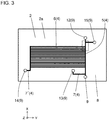
- FIG. 3 schematically shows the example first flow path device 2 as a particle separating device.
- FIG. 3 is a plan view of the first flow path device 2 in top perspective.
- Particle separating device first flow path device
- the first flow path device 2 is a particle separating device for separating and collecting target particles from a liquid (specimen) containing multiple types of particles including the target particles to be separated.
- the first flow path device 2 has a pre-separation flow inlet 12 to receive a fluid containing target particles to be separated, a main flow path 5 connected to the pre-separation flow inlet 12, multiple branch flow paths 6 connected to the main flow path 5, and a post-separation flow outlet 13 to allow discharge of the first fluid containing the target particles after being separated.
- the first flow path device 2 is substantially plate-like. More specifically, the flow path device 2 includes a plate-like base 2a having a separating flow path 4 inside.
- the separating flow path 4 includes the straight main flow path 5 and the multiple branch flow paths 6 connected to and branching from the main flow path 5.
- a specimen e.g., blood
- particles second particles, or for example, erythrocytes
- target particles first particles, or for example, leukocytes
- the branch flow paths 6 branch from the main flow path 5 to receive the second particles.
- particles flowing into the branch flow paths 6 are not limited to the second particles. Particles different from the second particles (e.g., third particles) may flow into the branch flow paths 6.
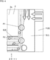
- FIG. 4 schematically shows the main flow path 5 and the branch flow paths 6 separating the first particles and the second particles.
- FIG. 4 is an enlarged plan view of the region enclosed by the broken line in FIG. 3 .
- the larger circles indicate first particles PI
- the smaller circles indicate second particles P2.
- the hatched arrows in X-direction indicate the main flow
- the white arrows in Y-direction indicate a pressing flow (described later).
- the hatched region in the figure indicates a lead-in flow (described later).
- the separating flow path 4 in the embodiment of the present disclosure includes the single main flow path 5 and the multiple branch flow paths 6 orthogonal to and connected to the main flow path 5 along the main flow path 5.
- the first flow path device 2 generates a lead-in flow in the main flow path 5 flowing from the main flow path 5 to the branch flow paths 6 by adjusting, for example, the cross-sectional areas and the lengths of the main flow path 5 and the branch flow paths 6 and the flow velocity of the specimen.
- the first flow path device 2 generates a pressing flow in the separating flow path 4 for pressing the specimen through the main flow path 5 into the branch flow paths 6. As shown in FIG.
- the branch flow paths 6 that receive the lead-in flow each have a width smaller than the size of the first particles P1 (target particles) flowing in the specimen and larger than the size of the second particles P2 (other particles).
- the second particles P2 are led into the branch flow paths 6.
- the lead-in flow is pressed by the pressing flow and moves along the main flow path 5 adjacent to the branch flow paths 6.
- the lead-in flow has a width larger than the distance between the edge of the main flow path 5 and the center of gravity of the second particles P2 flowing in the specimen and smaller than the distance between the edge and the center of gravity of the first particles P1.
- the second particles P2 are effectively led into the branch flow paths 6. This allows the first particles P1 to be separated as target particles in the specimen and collected with the flow through the main flow path 5. This also allows the second particles P2 to be separated in the specimen and collected with the flow through the branch flow paths 6.
- the first flow path device 2 may be used to separate erythrocytes and leukocytes in blood as a specimen.
- Erythrocytes in blood have, for example, a size of 6 to 8 ⁇ m and the center of gravity 3 to 4 ⁇ m away from the edge.
- Leukocytes have, for example, a size of 10 to 30 ⁇ m and the center of gravity 5 to 15 ⁇ m away from the edge.
- the main flow path 5 may have, for example, a cross-sectional area of 300 to 1000 ⁇ m 2 and a length of 0.5 to 20 mm.
- the main flow path 5 may have, for example, a cross section having an area within the above range, a width of about 30 ⁇ m, and a height of about 20 ⁇ m.
- the branch flow paths 6 may each have, for example, a cross-sectional area of 100 to 500 ⁇ m 2 and a length of 3 to 25 mm.
- the branch flow paths 6 may have, for example, a cross section having an area within the above range, a width of about 15 ⁇ m, and a height of about 20 ⁇ m.
- the flow velocity in the separating flow path 4 may be 0.2 to 5 m/s, for example. With these dimensions, the lead-in flow may have a width of, for example, 2 to 15 ⁇ m, allowing effective separating of erythrocytes and leukocytes in blood.
- the target particles may be any of various extracellular vesicles, instead of leukocytes or erythrocytes.
- extracellular vesicles include exosomes (30 to 200 nm), microvesicles (200 to 1000 nm), and large oncosomes (1 to 10 ⁇ m).
- the target particles may be inorganic matter or target fine particles in a fluid, such as a suspension containing fine powder.
- the separating flow path 4 may have a shape and dimensions designed as appropriate for, for example, the size of the target particles to be separated.
- the first flow path device 2 has multiple first openings 9 in one or both of the upper surface and the lower surface of the base 2a. At least two of the first openings 9 are flow inlets for receiving a specimen and a fluid to flow into the main flow path 5.
- the flow inlets include the pre-separation flow inlet 12 and a pressing-flow inlet 15.
- the pre-separation flow inlet 12 receives a specimen as a fluid containing target particles (e.g., the first particles PI) to be separated, and supplies the specimen to the main flow path 5.
- the pressing-flow inlet 15 is orthogonally connected to a portion of the main flow path 5 upstream from and opposite to the multiple branch flow paths 6 with respect to the main flow path 5.
- the pressing-flow inlet 15 receives a fluid for generating a pressing flow.
- the first opening 9 as the pre-separation flow inlet 12 may be circular and have a dimension of, for example, 1 to 3 mm.
- the flow paths in the separating flow path 4 may have the same height.
- the pre-separation flow inlet 12 may have a depth, for example, corresponding to the distance from the opening in the upper surface of the base 2a to the bottom surface of the main flow path 5.
- the first opening 9 as the pressing-flow inlet 15 may be circular and have a dimension of, for example, 1 to 3 mm.
- a flow path for a pressing flow may have the same height as the other flow paths in the separating flow path 4.
- the pressing-flow inlet 15 may have a depth, for example, corresponding to the distance from the opening in the upper surface of the base 2a to the bottom surface of the main flow path 5.
- the separating flow path 4 further includes a collection flow path 7 connected to the main flow path 5.
- the collection flow path 7 may be used to collect the separated first particles P1.
- the first particles P1 are collected in the collection flow path 7 using a pressing flow.
- the separating flow path 4 may also include a disposal flow path 7' connected to the multiple branch flow paths 6.
- the second particles P2 separated by the branch flow paths 6 may be collected or disposed through the disposal flow path 7'.
- the multiple branch flow paths 6 collect the second particles P2, which are then collected in the single disposal flow path 7' connected to the branch flow paths 6.
- the fluid containing the first particles P1 may flow from the main flow path 5 to the collection flow path 7 and may then be disposed.
- the first flow path device 2 includes the plate-like base 2a.
- the plate-like base 2a has the separating flow path 4 inside.
- the first flow path device 2 has a pair of first upper and lower surfaces 8 at the top and bottom in the thickness direction (Z-direction).
- the separating flow path 4 has the multiple first openings 9 in one or both of the pair of first upper and lower surfaces 8.
- first upper surface 10 For convenience, one of the pair of first upper and lower surfaces 8 is referred to as a first upper surface 10 and the other as a first lower surface 11 in the embodiment of the present disclosure.
- the first upper surface 10 of the pair of first upper and lower surfaces 8 is located in the positive Z-direction, and the first lower surface 11 is located in the negative Z-direction.
- at least one of the multiple first openings 9 is located in the first lower surface 11.
- the multiple first openings 9 include at least the pre-separation flow inlet 12, the post-separation flow outlet 13, and at least one disposal flow outlet 14.
- the pre-separation flow inlet 12 receives a specimen to flow into the main flow path 5.
- the post-separation flow outlet 13 discharges the first fluid containing the separated first particles P1 (target particles) for collection from the collection flow path 7.
- the disposal flow outlet 14 disposes, for collection, the components of the specimen excluding the first particles P1.
- the first openings 9 include the pressing-flow inlet 15 for receiving a fluid for generating a pressing flow that presses the specimen toward the branch flow paths 6.
- the disposal flow outlet 14 is connected to the main flow path 5 and the disposal flow path 7'. The fluid disposed through the disposal flow outlet 14 is collected through a through-hole 14' in the second flow path device 3 (described later).
- the first flow path device 2 is rectangular as viewed from above.
- the first upper and lower surfaces 8 are flat.
- the first flow path device 2 may not be rectangular as viewed from above.
- the first upper and lower surfaces 8 may not be flat.
- the first upper and lower surfaces 8 (the first upper surface 10 and the first lower surface 11) may have different shapes.
- the first flow path device 2 is formed from, for example, polydimethylsiloxane (PDMS) or polymethyl methacrylate or acrylic resin (PMMA).
- the first flow path device 2 may have a thickness of, for example, 1 to 5 mm.
- the first flow path device 2 may be, for example, rectangular as viewed from above with short sides of 10 to 20 mm and long sides of 10 to 30 mm.
- the first flow path device 2 is formed by, for example, preparing two substrates, forming grooves for the separating flow path 4 on one of the substrates, and placing the other substrate to cover the grooves and bonding the substrates together to complete the base 2a having the separating flow path 4 inside.
- the second flow path device 3 is used to measure target particles separated and collected by the first flow path device 2.
- the second flow path device 3 includes a first region 21 receiving the first flow path device 2, and a second region 22 defining a region to allow measurement of target particles.
- the second flow path device 3 also has a first flow inlet 23 to receive the first fluid, and a second flow inlet to receive a second fluid free from the target particles (described later).
- the second flow path device 3 also has a first flow path 16 located in the second region 22 and connected to the first flow inlet 23 to allow a flow of the first fluid, and a second flow path (described later) located in the second region 22 and connected to the second flow inlet to allow a flow of the second fluid.
- the second flow path device 3 is substantially plate-like.
- the second flow path device 3 has the first flow path 16 connected to the separating flow path 4 in the first flow path device 2.
- the second flow path device 3 is translucent.
- the first fluid containing target particles separated and collected by the first flow path device 2 flows through the first flow path 16, in which the target particles are measured with an optical sensor (described later). More specifically, the target particles are measured by measuring the intensity of light passing through the first fluid containing the target particles through the first flow path 16.
- the second flow path device 3 includes a plate-like base having flow paths inside.
- the plate-like base has the first flow path 16 inside.
- the second flow path device 3 has a pair of second upper and lower surfaces 17 at the top and bottom in the thickness direction (Z-direction).
- the first flow path 16 has multiple second openings 18 in one or both of the pair of second upper and lower surfaces 17.
- one of the pair of second upper and lower surfaces 17 is referred to as a second upper surface 19 and the other as a second lower surface 20 in the embodiment of the present disclosure.
- the second upper surface 19 of the pair of second upper and lower surfaces 17 is located in the positive Z-direction, and the second lower surface 20 is located in the negative Z-direction.
- the second flow path device 3 is rectangular as viewed from above.
- the second upper and lower surfaces 17 are flat.
- the second flow path device 3 may not be rectangular as viewed from above.
- the second upper and lower surfaces 17 may not be flat.
- the second upper and lower surfaces 17 (the second upper surface 19 and the second lower surface 20) may have different shapes.
- the second flow path device 3 is formed from, for example, PMMA or cycloolefin polymer (COP).
- the second flow path device 3 may have a thickness of, for example, 0.5 to 5 mm.
- the second flow path device 3 may be, for example, rectangular as viewed from above with short sides of 20 to 40 mm and long sides of 20 to 80 mm.
- the second flow path device 3 is formed by, for example, preparing two substrates, forming a groove for the first flow path 16 on one of the substrates, and placing the other substrate to cover the groove and bonding the substrates together to complete the base having the first flow path 16 inside.
- FIGs. 5A and 5B are partial schematic views of the example particle separating and measuring device 1 including the first flow path device 2 as a particle separating device and the second flow path device 3 as a particle measuring device.
- FIG. 5A is an enlarged cross-sectional view of the region enclosed by the broken line in FIG. 2 .
- FIG. 5B is an enlarged plan view of the region enclosed by the broken line in FIG. 5A , showing the profiles of the flow paths at the joint.
- the second flow path device 3 In the second flow path device 3 according to the embodiment of the present disclosure, at least one of the multiple second openings 18 is located in the second upper surface 19.
- the second upper surface 19 includes the first region 21 receiving the first flow path device 2 with the first lower surface 11 on the first region 21.
- One of the first openings 9 in the first lower surface 11 as the post-separation flow outlet 13 is connected to one of the second openings 18 in the second upper surface 19 as the first flow inlet 23.
- the flow path in the first flow path device 2 is directly connected to the flow path in the second flow path device 3. This allows target particles in a specimen to be separated, collected, and measured sequentially, improving processing efficiency.
- the particle separating and measuring device 1, in which the first flow path device 2 and second flow path device 3 are stacked in the thickness direction, is downsized.
- the second flow path device 3 has the second upper surface 19 including the first region 21 receiving the first flow path device 2, and the second region 22 defining the region to allow measurement of target particles.
- the first flow path 16 in the second flow path device 3 extends over the first region 21 to the second region 22, whereas the first flow path device 2 extends in the first region 21 in the second flow path device 3 alone.
- the first flow path 16 is thus located in the second region 22 without overlapping the first flow path device 2.
- the second region 22 is used for measuring particles with the first flow path 16 used as a measurement flow path.
- the particle separating and measuring device 1 may include a light reflector in the second region 22 as described later.
- the first flow path device 2 and the second flow path device 3 may be formed from different materials.
- the first flow path device 2 is formed from PDMS
- the second flow path device 3 is formed from COP.
- the first flow path device 2 is above the second flow path device 3. More specifically, the first flow path device 2 is located on the first region 21 in the second upper surface 19 of the second flow path device 3.
- the first fluid containing the target particles separated and collected by the first flow path device 2 efficiently flows into the second flow path device 3 using the gravity. This reduces accumulation of the first fluid containing the target particles in the flow path, for example, at a joint between the first flow path device 2 and the second flow path device 3.
- the present disclosure does not exclude embodiments in which the first flow path device 2 is located on the second lower surface 20 of the second flow path device 3.
- the multiple second openings 18 include the first flow inlet 23 and a first flow outlet 24.
- the first flow inlet 23 receives the first fluid containing the separated target particles to flow into the first flow path 16.
- the first flow outlet 24 discharges the first fluid from the first flow path 16 for collection.
- the first flow inlet 23 has an opening located in the second upper surface 19.
- the first flow inlet 23 faces and connects to the post-separation flow outlet 13 in the first flow path device 2.
- the first flow outlet 24 is located in the second lower surface 20.
- the first flow path device 2 is placed on the first region 21 in the second upper surface 19 of the second flow path device 3.
- the post-separation flow outlet 13 in the first flow path device 2 faces and connects to the first flow inlet 23 in the second flow path device 3.
- the post-separation flow outlet 13 and the first flow inlet 23 each have a circular opening.
- the first flow inlet 23 has the opening larger than the opening of the post-separation flow outlet 13.
- the post-separation flow outlet 13 has the opening connected to the opening of the first flow inlet 23 at a peripheral portion of the opening of the first flow inlet 23.
- the first fluid containing the target particles separated through the separating flow path 4 flows through the separating flow path 4 (the collection flow path 7) and reaches the joint with the post-separation flow outlet 13.
- the target particles tend to immediately fall into any hole in a flow path upon reaching the hole.
- the target particles can thus fall into the post-separation flow outlet 13 without flowing to the center of the circular opening of the post-separation flow outlet 13.
- the opening of the post-separation flow outlet 13 has the periphery opposite to the joint with the separating flow path 4 (the collection flow path 7) and located at a peripheral portion of the opening of the first flow inlet 23. This structure allows the target particles to efficiently flow into the first flow inlet 23 at the center of the first flow inlet 23 and further flow through a vertical portion 25 into the first flow path 16 at the center.
- This structure reduces uneven distribution of the target particles in the flow paths.
- the fluid flows into the first flow path 16 with reduced uneven distribution of the target particles.
- the first flow path 16 includes the vertical portion 25 connected to the first flow inlet 23 (the second opening 18) and extending in the thickness direction, and a planar portion 26 connected to the vertical portion 25 and extending in a direction in a plane over the second region 22.
- the vertical portion 25 is circular in cross section similarly to the opening of the first flow inlet 23, and has the same dimension as the first flow inlet 23.
- the cross section of the vertical portion 25 is a transverse section parallel to the XY plane.
- the first flow path 16 including the vertical portion 25 reduces accumulation of the first fluid at the joint with the separating flow path 4.
- the first flow path 16 can hold the first fluid in the planar portion 26 for measurement of particles, thus allowing reliable measurement.
- the post-separation flow outlet 13 may have an opening with a dimension of, for example, 0.5 to 3 mm, and more specifically, 1.5 to 2 mm.
- the opening of the first flow inlet 23 and the vertical portion 25 may each have a dimension (diameter) of, for example, 1.5 to 4 mm, and more specifically, 2.5 to 3 mm.
- the first flow inlet 23 has the opening larger than the opening of the post-separation flow outlet 13.
- the post-separation flow outlet 13 has the opening connecting to the opening of the first flow inlet 23 and located at a peripheral portion of the opening of the first flow inlet 23.
- the post-separation flow outlet 13 and the first flow inlet 23 may have the openings with their peripheries out of alignment with each other.
- the post-separation flow outlet 13 may have the opening with the periphery located inside the periphery of the opening of the first flow inlet 23.
- the post-separation flow outlet 13 may have the opening with the periphery located slightly outside the periphery of the opening of the first flow inlet 23 within assembly tolerances in manufacturing.
- the planar portion 26 may have a width of, for example, 3 to 6 mm.
- the vertical portion 25 may have a length of, for example, 0.5 to 1 mm.
- the planar portion 26 may have a height of, for example, 0.5 to 2 mm.
- the post-separation flow outlet 13 and the first flow inlet 23 have the openings with their centers aligning along the first flow path 16.
- the post-separation flow outlet 13 may have the opening located upstream along the first flow path 16.
- the post-separation flow outlet 13 having the opening located upstream along the first flow path 16 allows the target particles to efficiently flow into the first flow inlet 23 at the center of the first flow inlet 23 and further flow through the vertical portion 25 into the first flow path 16 at the center.
- the fluid flowing through the first flow path 16 allows effective dispersion of the target particles in the fluid. This allows accurate measurement.
- the separating flow path 4 (the collection flow path 7) may be connected to the post-separation flow outlet 13 from downstream along the first flow path 16. This allows the target particles to efficiently flow into the first flow inlet 23 at the center of the first flow inlet 23 and further flow through the vertical portion 25 effectively into the first flow path 16 at the center.
- the fluid flowing through the first flow path 16 allows uniform dispersion of the target particles in the fluid. This allows accurate measurement.
- the first flow path 16 with the vertical portion 25 includes the planar portion 26.
- the planar portion 26 is connected to the vertical portion 25 and extends in a direction in a plane over the second region 22.
- the first flow path 16 with the vertical portion 25 reduces accumulation of the first fluid at the joint with the separating flow path 4, and also reduces the uneven distribution of the separated target particles.
- the first flow path 16 can hold the first fluid in the planar portion 26 for measurement of particles, thus allowing reliable measurement.
- a sheet member 44 is placed between the first flow path device 2 and the second flow path device 3.
- the sheet member 44 is optional and may not be included as in the example shown in FIG. 5A .
- the first flow path device 2 and the second flow path device 3 may be directly connected to each other with a silane coupling agent applied to one or both of the first lower surface 11 of the first flow path device 2 and the second upper surface 19 of the second flow path device 3.
- the sheet member 44 may be placed between the first lower surface 11 of the first flow path device 2 and the second upper surface 19 of the second flow path device 3, as in the example shown in FIG. 2 .
- the particle separating and measuring device 1 may include the sheet member 44 between the first flow path device 2 and the second flow path device 3. More specifically, the first flow path device 2 may be placed on the second flow path device 3 with the sheet member 44 in between, and the post-separation flow outlet 13 and the first flow inlet 23 may connect to each other with a through-hole 45 in the sheet member 44.
- the through-hole 45 in the sheet member 44 may have a circular opening with substantially the same dimension as the opening of the post-separation flow outlet 13, as shown in FIGs. 6A and 6B .
- the openings with substantially the same dimension may include openings having dimensional differences within manufacturing tolerances.
- the through-hole 45 is smaller than the opening of the first flow inlet 23.
- the structure allows the target particles to efficiently flow from the post-separation flow outlet 13 through the through-hole 45 into the first flow inlet 23 at the center of the first flow inlet 23 and further flow through the vertical portion 25 effectively into the first flow path 16 at the center.
- the fluid flowing through the first flow path 16 allows uniform dispersion of the target particles in the fluid. This allows accurate measurement.
- the through-hole 45 in the sheet member 44 may have a uniform dimension in the vertical direction. In some embodiments, the through-hole 45 may be flared downward. The through-hole 45 flared downstream may increase the distribution of target particles flowing through the through-hole 45 into the first flow inlet 23.
- the sheet member 44 as an intermediate layer can firmly bond the devices, thus stably forming the particle separating and measuring device 1.
- the through-hole 45 between the post-separation flow outlet 13 and the first flow inlet 23 may have the opening with an appropriate dimension that falls between the dimensions of the openings of the post-separation flow outlet 13 and the first flow inlet 23. This effectively prevents accumulation of the first fluid and the target particles at the joint between the first flow path device 2 and the second flow path device 3.
- the sheet member 44 reduces leakage of, for example, the first fluid from the bonding surfaces of the first flow path device 2 and the second flow path device 3.
- the sheet member 44 also serves as an intermediate layer for bonding materials that are difficult to adhere to each other.
- the sheet member 44 may be of a material such as silicone or PDMS.
- the sheet member 44 also accommodates any deformation of the first lower surface 11 and the second upper surface 19 as bonding surfaces.
- the sheet member 44 may have multiple through-holes as appropriate, in addition to the through-hole 45 between the post-separation flow outlet 13 and the first flow inlet 23.
- the multiple through-holes, including the through-hole 45 face multiple first openings 9 and second openings 18. The fluid thus flows from the first flow path device 2 through these through-holes to the second flow path device 3.
- the sheet member 44 may have a thickness of, for example, about 0.5 to 3 mm.
- the sheet member 44 having a thickness of about 2 mm can sufficiently accommodate any deformation of the bonding surfaces, and also shorten the distance between the post-separation flow outlet 13 and the first flow inlet 23.
- the sheet member 44 with such a thickness can also reduce cracks or other damage when the first flow path device 2 and the second flow path device 3 are bonded together.
- the sheet member 44 may have any appropriate dimensions (area) large enough for adhesion around the through-hole 45 and smaller than or equal to the dimensions of the first lower surface 11 of the first flow path device 2.
- the sheet member 44 may not be a single sheet, and may be a combination of multiple sheets with predetermined shapes and dimensions.
- the first flow path device 2 and the second flow path device 3 may be directly connected to the sheet member 44, or may be connected with an adhesive applied to the upper and lower surfaces of the sheet member 44.
- the adhesive may be, for example, a photo-curable resin curable with ultraviolet light or a thermoplastic resin.
- the through-hole 45 in the sheet member 44 may have the opening larger than the opening of the post-separation flow outlet 13 and smaller than the opening of the first flow inlet 23, as in a cross-sectional view of FIG. 7A similar to FIG. 6A .
- the through-hole 45 may have the opening with a dimension of 2 to 2.5 mm when the post-separation flow outlet 13 has the opening with a dimension of 1.5 to 2 mm and the first flow inlet 23 has the opening with a dimension of 2.5 to 3 mm.
- the through-hole 45 may have a combination of dimensions within the above ranges to have the opening larger than the opening of the post-separation flow outlet 13 and smaller than the opening of the first flow inlet 23.
- the structure allows the target particles to efficiently flow and spread from the post-separation flow outlet 13 through the through-hole 45 into the first flow inlet 23 at the center of the first flow inlet 23 and further flow through the vertical portion 25 effectively into the first flow path 16 at the center.
- the fluid flowing through the first flow path 16 allows uniform dispersion of the target particles in the fluid. This allows accurate measurement.
- the particle separating and measuring device 1 may include, between the first flow path device 2 and the second flow path device 3, the sheet member 44 having a higher hardness than the first flow path device 2 and a lower hardness than the second flow path device 3. This allows the flow path in the softer first flow path device 2 to maintain its shape on the flat, harder base sheet member 44 between the first flow path device 2 and the sheet member 44.
- the sheet member 44 is tightly as well as firmly bonded to the second flow path device 3, serving as the harder base, between the second flow path device 3 and the sheet member 44.
- the bonding surfaces of the first flow path device 2 and the sheet member 44 may have substantially the same surface roughness.
- the bonding surfaces of the sheet member 44 and the second flow path device 3 may have substantially the same surface roughness. More specifically, these bonding surfaces may have an arithmetic mean roughness Ra of about 0.005 to 0.05 ⁇ m.
- the first flow path device 2 may have a hardness of at least 30 and lower than 80 under IRHD
- the sheet member 44 may have a hardness of about 80 under IRHD
- the second flow path device 3 may have a hardness of higher than 80 under IRHD
- the first flow path device 2 may be formed from PDMS, the sheet member 44 from silicone, and the second flow path device 3 from COP or PMMA to achieve a combination of the above hardness. More specifically, PDMS is about 30 under IRHD, silicone is about 80 under IRHD, and COP exceeds 80 under IRHD (about 50 in Rockwell hardness). These materials may be used to achieve a combination of the above hardness.
- the hardness can be measured by pressing an unsharp indenter into an object to be measured with a predetermined force, and measuring and quantifying its deformation.
- durometer hardness the force for pressing the indenter is applied with a spring.
- IRHD the force for pressing the indenter is applied with, for example, a weight for applying a constant load.
- Durometer hardness which can be measured with a simpler instrument, is more common and may be used in the present embodiment.
- FIGs. 8 and 9 schematically show the example second flow path device 3 included in the particle separating and measuring device 1.
- FIG. 8 is a plan view of the second flow path device 3 in top perspective.
- FIG. 9 is an enlarged plan view of the region enclosed by the broken line in FIG. 8 .
- Line A-A in FIG. 8 is at the same position as line A-A in FIG. 1 .
- the planar portion 26 in the first flow path 16 may have a greater width than the vertical portion 25 at least at the joint with the vertical portion 25. This reduces accumulation of the first fluid at the joint between the planar portion 26 and the vertical portion 25.
- the planar portion 26 may include a first planar portion 27 connected to the vertical portion 25, and a second planar portion 28 connected to the first planar portion 27 and having a greater width than the first planar portion 27.
- the first planar portion 27 and the second planar portion 28 may be connected to each other with a width-increasing portion 16a in between.
- the width-increasing portion 16a has a flow path width increasing downstream along the flow of the first fluid from the joint between the vertical portion 25 and the first flow path 16.
- the second flow path device 3 may include the width-increasing portion 16a between the first flow inlet 23 and the second planar portion 28 located in the second region 22 and used as the measurement portion in the first flow path 16.
- the width-increasing portion 16a has a flow path width increasing downstream along the flow of the first fluid.
- the width-increasing portion 16a causes a flow of the first fluid to spread in the width direction to disperse the target particles contained in the first fluid, reducing unevenness of the target particles for measurement. This facilitates, in the second planar portion 28, diffusion of particles (e.g., the first particles PI) separated and collected by the first flow path device 2.
- the first planar portion 27 may have a width of, for example, 0.5 to 3 mm.
- the second planar portion 28 may have a width of, for example, 1 to 5 mm.
- the second planar portion 28 may have a width of, for example, 2 to 10 times the width of the first planar portion 27.
- the width-increasing portion 16a has a width gradually increases at the joint between the first planar portion 27 and the second planar portion 28.
- the width-increasing portion 16a is flared in the width direction.
- the flared portion widens toward the end at 20 to 40° on each side of the centerline across the width of the planar portion 26 (the first planar portion 27 and the second planar portion 28).
- the flared portion may have a length of about 3 to 5 mm.
- the width-increasing portion 16a may widen in a curved or stepwise manner, rather than widening gradually in a straight manner.
- the width-increasing portion 16a connecting the first planar portion 27 to the second planar portion 28 may have a flow path width increasing stepwise, for example, from 1 mm to 2.5 mm, and from 2.5 mm to 5 mm.
- the width-increasing portion 16a having such a sharply increasing flow path width allows the second planar portion 28 to have a flow path width twice or more that of the first planar portion 27. This allows a vortex to occur in the first fluid flowing through these portions, facilitating agitation and mixing of the target particles contained in the first fluid.
- the second planar portion 28 may have a greater height than the first planar portion 27.
- the second flow path device 3 may include a height-increasing portion 16b between the first flow inlet 23 and the second planar portion 28 located in the second region 22 and used as the measurement portion in the first flow path 16.
- the height-increasing portion 16b has a flow path height increasing downstream along the flow of the first fluid.
- the height-increasing portion 16b causes a flow of the first fluid to spread in the height direction to disperse the target particles contained in the first fluid, reducing unevenness of the target particles for measurement.
- the flow path has a height increasing over a relatively short distance and thus allows a vortex to occur in the flow of fluid, facilitating agitation of the target particles. This facilitates the diffusion of the separated target particles (e.g., the first particles PI).
- the first planar portion 27 may have a height of, for example, 0.2 to 1 mm.
- the second planar portion 28 may have a height of, for example, 1 to 5 mm.
- the height-increasing portion 16b has a height gradually increasing at the joint between the first planar portion 27 and the second planar portion 28. In other words, the height-increasing portion 16b is flared in the height direction.
- the first planar portion 27 may have a height of 0.5 mm
- the second planar portion 28 may have a height of 1 mm, with the flared portion being flared at about 45°.
- the height-increasing portion 16b may be immediately upstream from the width-increasing portion 16a.
- the width-increasing portion 16a and height-increasing portion 16b may be closest possible to each other.
- the height-increasing portion may be upstream from the width-increasing portion.
- the second flow path device 3 may further include, in addition to the first flow path 16, a third flow path 29 connected to the first flow path 16.
- the third flow path 29 may be connected to the planar portion 26 in the first flow path 16.
- the third flow path 29 receives, for example, a gas for forcing out the fluid accumulating in the planar portion 26. This reduces fluid accumulation in the first flow path 16.
- the third flow path 29 is connected to the joint between the vertical portion 25 and the planar portion 26 in the first flow path 16 in the second flow path device 3 according to the embodiment of the present disclosure.
- the third flow path 29 has one end connected to the first flow path 16.
- the third flow path 29 has the other end being a third opening 30 located in the pair of second upper and lower surfaces 17. More specifically, the third flow path 29 has the third opening 30 located in one of the pair of second upper and lower surfaces 17 (the second upper surface 19 in the embodiment of the present disclosure).
- the third opening 30 receives a displacement fluid (e.g., gas) for forcing a fluid out of the second planar portion 28 in the second flow path 36.
- a displacement fluid e.g., gas
- the third flow path 29 may have a portion connected to the first flow path 16 and at least partially extending along the extension of the planar portion 26 (the second planar portion 28) in the first flow path 16.
- the third flow path 29 may have a portion connected to the first flow path 16 and at least partially having the same shape as a portion of the first flow path 16 connected to the third flow path 29. This eliminates a step at a joint between the first flow path 16 and the third flow path 29, reducing accumulation of the fluid at the joint.
- the third flow path 29 may include multiple straight portions 31 extending in a predetermined direction and arranged in a direction intersecting the direction.
- the third flow path 29 including the multiple straight portions 31 reduces the fluid flowing back from the first flow path 16 and leaking from the third opening 30.
- the first openings 9 as the pre-separation flow inlet 12 and the post-separation flow outlet 13 may be in the same surface (the first lower surface 11 in the embodiment of the present disclosure). In this case, a specimen flows into the first flow path device 2 from below (in the negative Z-direction). In this structure, the second particles P2 having a greater specific gravity than the first particles P1 sink and are thus easily separated.
- the second flow path device 3 may further include a fourth flow path 32 different from the first flow path 16 and the third flow path 29.
- the fourth flow path 32 may have multiple fourth openings 33 located in one or both of the pair of second upper and lower surfaces 17.
- the fourth flow path 32 allows a specimen to flow before target particles are separated in the specimen.
- the fourth flow path 32 in the second flow path device 3 allows the specimen to flow to reduce foreign matter before entering the first flow path device 2.
- the multiple fourth openings 33 include a fourth flow inlet 34 and a fourth flow outlet 35.
- the fourth flow inlet 34 is an opening for receiving the specimen to flow into the fourth flow path 32.
- the fourth flow outlet 35 is an opening for discharging the specimen from the fourth flow path 32.
- the fourth flow inlet 34 is open to receive the specimen from outside.
- the fourth flow outlet 35 is connected to the pre-separation flow inlet 12 in the first flow path device 2.
- the fourth flow inlet 34 and the fourth flow outlet 35 may be in the second upper surface 19. In this case, an operator can handle the device from above for, for example, connecting the device with an external component to supply a specimen.
- the fourth flow inlet 34 is in the same surface as the first flow outlet 24.
- the fourth flow outlet 35 is also in the same surface as the first flow outlet 24.
- the fourth flow inlet 34 is in the same surface as the third opening 30.
- the second flow path device 3 may further include a second flow path 36 different from the first flow path 16, the third flow path 29, and the fourth flow path 32.
- the first flow path 16 is used for the first fluid containing the target particles separated and collected by the first flow path device 2.
- the second flow path 36 is used for the second fluid free from the target particles.
- the second flow path 36 is used for the second fluid for comparison or calibration for measuring the first fluid.
- the second fluid may be the same fluid as the first fluid but excluding the target particles, or may be a different fluid.
- the first flow path 16 and the second flow path 36 may sequentially undergo measurement to determine the difference in light intensity between them. The difference can be used to estimate the number of target particles. The results are less susceptible to deterioration of the optical sensor.
- the second flow path 36 has multiple fifth openings 37 located in the pair of second upper and lower surfaces 17.
- the fifth openings 37 include a second flow inlet 38 and a second flow outlet 39.
- the second flow inlet 38 is an opening for receiving the second fluid to flow into the second flow path 36.
- the second flow outlet 39 is an opening for discharging the second fluid from the second flow path 36.
- the second flow path 36 includes a measurement portion similarly shaped to the second planar portion 28 in the first flow path 16.
- the second flow inlet 38 as one of the multiple fifth openings 37 is in the same surface as the third opening 30. In this case, an operator can handle the device on the same surface from above for, for example, supplying and discharging the second fluid.
- the second flow outlet 39 may be in the second lower surface 20.
- the second flow path device 3 may further include a sixth flow path 40 different from the first flow path 16, the third flow path 29, the fourth flow path 32, and the second flow path 36.
- the sixth flow path 40 has multiple sixth openings 41 in one or both of the pair of second upper and lower surfaces 17.
- the multiple sixth openings 41 include a sixth flow inlet 42 and a sixth flow outlet 43.
- the sixth flow inlet 42 is an opening for receiving a fluid for generating a pressing flow to flow into the sixth flow path 40.
- the sixth flow outlet 43 is an opening for discharging the fluid for generating a pressing flow from the sixth flow path 40.
- the sixth flow inlet 42 is located to receive the fluid.
- the sixth flow outlet 43 is connected to the pressing-flow inlet 15 in the first flow path device 2.
- the third flow path 29, the fourth flow path 32, the second flow path 36, and the sixth flow path 40 may be formed in the same manner as the first flow path 16.
- the particle separating apparatus includes the first flow path device 2 as a particle separating device, a first pump for pumping a specimen into the pre-separation flow inlet 12, and a second pump for pumping a fluid into the pressing-flow inlet 15.
- the particle separating device is the first flow path device 2 described above.
- the first flow path device 2 has the pre-separation flow inlet 12 connected to the first pump with, for example, a first tube.
- the first pump delivers a specimen, which then flows through the first tube into the pre-separation flow inlet 12 in the first flow path device 2.
- the first flow path device 2 has the pressing-flow inlet 15 connected to the second pump with, for example, a second tube.
- the second pump delivers a fluid, which flows through the second tube into the pressing-flow inlet 15 in the first flow path device 2.
- target particles e.g., the first particles PI
- the first and second pumps may be any of a variety of known pumps that can pump a fluid.
- the first pump may be capable of pumping a small amount of fluid (e.g., blood) containing particles into the pre-separation flow inlet 12 in the first flow path device 2 at a constant flow velocity.
- the second pump may be capable of pumping a fluid for generating a pressing flow (e.g., phosphate buffered saline, or PBS) into the pressing-flow inlet 15 in the first flow path device 2 at an appropriate flow rate, flow velocity, and pressure.
- the first and second pumps may be, for example, syringe pumps. Other pumps such as electroosmotic pumps, peristaltic pumps, and gas pumps may also be used.
- the first and second tubes may be formed from any of a variety of known materials in accordance with the fluid to be used.
- silicone tubes may be used for blood as the specimen and PBS as the fluid. These tubes are optional and may be eliminated when, for example, the first flow path device 2 is connected to the first and second pumps directly or with adapters.
- the apparatus includes the particle separating and measuring device according to the embodiment of the present disclosure.
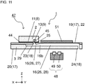
- FIGs. 11 and 12 schematically show a particle separating and measuring apparatus 47.
- FIG. 11 is a cross-sectional view of the particle separating and measuring apparatus 47 as viewed from the same viewpoint as FIGs. 2 and 10 . Some reference numerals are the same as those in FIGs. 2 and 10 and thus are not described.
- FIG. 12 is a block diagram of the particle separating and measuring apparatus 47, showing its example overall structure.
- the particle separating and measuring apparatus 47 includes the particle separating and measuring device 1 and an optical sensor 48.
- the optical sensor 48 includes a light-emitting element 49 and a light receiving element 50.
- the first flow path device 2 in the particle separating and measuring device 1 separates intended target particles (e.g., the first particles PI) in the specimen.
- the target particles then flow into the first flow path 16 (the second planar portion 28) in the second flow path device 3 in the particle separating and measuring device 1.
- the optical sensor 48 emits light with the light-emitting element 49 toward the target particles, and receives, with the light receiving element 50, light passing through the first flow path 16 (the second planar portion 28) for measurement of the particles.
- the light passing through the first flow path 16 is scattered, reflected, or absorbed by the particles (the first particles PI) in the first fluid and is thus attenuated in intensity.
- a calibration curve is predefined to show the relationship between the specimen having a known number of particles and the corresponding attenuation of light. The particles in the specimen can be measured by comparing the attenuation of received light measured by the particle separating and measuring apparatus 47 with the calibration curve.
- the particle separating and measuring apparatus 47 includes the particle separating and measuring device 1 according to the embodiment of the present disclosure described above, the optical sensor 48, and a controller.
- the optical sensor 48 emits light toward the measurement portions in the first flow path 16 and the second flow path 36 in the particle separating and measuring device 1, and receives light passing through the measurement portions in the first flow path 16 and the second flow path 36.
- the controller measures target particles by comparing the intensity of the light passing through the measurement portion in the first flow path 16 and received by the optical sensor 48 with the intensity of the light passing through the measurement portion in the second flow path 36 and received by the optical sensor 48.
- the light-emitting element 49 may be, for example, a light-emitting diode (LED).
- the light receiving element 50 may be, for example, a photodiode (PD).
- the light receiving element 50 is a PD formed on the upper surface of a semiconductor substrate and having regions of one conductivity type and another conductivity type.
- the light-emitting element 49 is an LED including multiple semiconductor layers stacked on the semiconductor substrate.
- the particle separating and measuring device 1 in the particle separating and measuring apparatus 47 includes a mirror 51 located in the second region 22 in the second upper surface 19 of the second flow path device 3.
- the optical sensor 48 has the light-emitting element 49 and the light receiving element 50 located adjacent to the second lower surface 20 of the second flow path device 3.
- light emitted from the light-emitting element 49 in the optical sensor 48 passes through the first flow path 16 (the second planar portion 28), is reflected by the mirror 51, and is then received by the light receiving element 50 in the optical sensor 48.
- the mirror 51 may be formed from, for example, aluminum or gold.
- the mirror 51 may be formed by, for example, depositing a metal foil with vapor deposition or sputtering.
- the particle separating and measuring apparatus 47 further includes a first supply unit 52 for supplying a specimen, a second supply unit 53 for supplying a fluid for generating a pressing flow, a third supply unit 54 for supplying a displacement fluid, and a fourth supply unit 55 for supplying the second fluid as a calibration fluid.
- the first to fourth supply units 52 to 55 are connected to the particle separating and measuring device 1.
- the first supply unit 52 is connected to the fourth flow inlet 34.
- the second supply unit 53 is connected to the sixth flow inlet 42.
- the third supply unit 54 is connected to the third opening 30.
- the fourth supply unit 55 is connected to the second flow inlet 38.
- the particle separating and measuring apparatus 47 includes a controller (not shown) for controlling the first supply unit 52, the second supply unit 53, the third supply unit 54, the fourth supply unit 55, and the optical sensor 48.
- the particle separating and measuring apparatus 47 includes the particle separating and measuring device 1 according to the embodiment of the present disclosure. Thus, the particle separating and measuring apparatus 47 separates target particles in a specimen for accurate and reliable measurement.
- the second flow path 36 has one end being the second flow outlet 39.
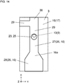
- the second flow path 36 may have one end connected to the first flow path 16 as shown in FIGs. 13 and 14 .
- This structure allows the second fluid in the second flow path 36 to be injected into the first flow path 16 to reduce the density of target particles (e.g., leukocytes) contained in the first fluid in the first flow path 16.
- FIGs. 13 and 14 are similar to FIGs. 8 and 9 as viewed from a similar viewpoint, and are not described in detail.
- the second flow path device 3 includes the second flow path 36 and the sixth flow path 40.
- the second flow path 36 may serve as the sixth flow path 40.
- the second flow path 36 and the sixth flow path 40 may be formed as a single flow path and connected to the separating flow path 4 (the pressing-flow inlet 15).
Landscapes
- Chemical & Material Sciences (AREA)
- Health & Medical Sciences (AREA)
- General Health & Medical Sciences (AREA)
- Physics & Mathematics (AREA)
- Analytical Chemistry (AREA)
- Dispersion Chemistry (AREA)
- Biochemistry (AREA)
- General Physics & Mathematics (AREA)
- Immunology (AREA)
- Pathology (AREA)
- Life Sciences & Earth Sciences (AREA)
- Hematology (AREA)
- Fluid Mechanics (AREA)
- Clinical Laboratory Science (AREA)
- Chemical Kinetics & Catalysis (AREA)
- Automatic Analysis And Handling Materials Therefor (AREA)
- Investigating Or Analysing Biological Materials (AREA)
- Separation Of Solids By Using Liquids Or Pneumatic Power (AREA)
- Sampling And Sample Adjustment (AREA)
- Physical Or Chemical Processes And Apparatus (AREA)
Abstract
Description
- The present disclosure relates to a particle separating and measuring device and a particle separating and measuring apparatus used to separate and measure specific particles from multiple types of particles contained in a liquid.
- A known particle separating device separates and extracts particles from a liquid using a microfluidic structure (micro flow paths) several to several hundred micrometers wide and having a flow inlet and multiple flow outlets (refer to, for example,
Japanese Patent Application Laid-Open No. 2012-76016 - The separated and extracted target particles are then measured for, for example, their type, number, density, or optical properties.
- A particle separating and measuring device according to an aspect of the present disclosure includes a first flow path device that is plate-like, and including a pre-separation flow inlet to receive a fluid containing target particles to be separated, a main flow path connected to the pre-separation flow inlet, a plurality of branch flow paths connected to the main flow path, and a post-separation flow outlet to discharge a first fluid containing the target particles after being separated, and a second flow path device that is plate-like, and including a first region receiving the first flow path device, a second region defining a region to allow measurement of the target particles, a first flow inlet to receive the first fluid, a second flow inlet to receive a second fluid free from the target particles, a first flow path located in the second region and connected to the first flow inlet to allow a flow of the first fluid, and a second flow path located in the second region and connected to the second flow inlet to allow a flow of the second fluid. The first flow path device having a lower surface having the post-separation flow outlet is on the second flow path device having an upper surface having the first flow inlet in the first region, with the post-separation flow outlet facing and connecting to the first flow inlet. The post-separation flow outlet and the first flow inlet each have a circular opening. The first flow inlet has the opening larger than the opening of the post-separation flow outlet. The post-separation flow outlet has the opening connecting to the opening of the first flow inlet at a peripheral portion of the opening of the first flow inlet.
- A particle separating and measuring apparatus according to another aspect of the present disclosure includes the particle separating and measuring device according to the above aspect, an optical sensor that emits light toward measurement portions of the first flow path and the second flow path in the particle separating and measuring device, and receives light passing through the measurement portions of the first flow path and the second flow path, and a controller that measures the target particles by comparing an intensity of the light passing through the measurement portion of the first flow path and received by the optical sensor with an intensity of the light passing through the measurement portion of the second flow path and received by the optical sensor.
-
-
FIG. 1 is a top view of an example particle separating and measuring device according to an embodiment of the present disclosure. -
FIG. 2 is a cross-sectional view of the example particle separating and measuring device according to the embodiment of the present disclosure. -
FIG. 3 is a plan view of an example first flow path device in the particle separating and measuring device according to the embodiment of the present disclosure. -
FIG. 4 is a partial plan view of the example first flow path device in the particle separating and measuring device according to the embodiment of the present disclosure. -
FIG. 5A is a partial cross-sectional view of the example particle separating and measuring device according to the embodiment of the present disclosure. -
FIG. 5B is a plan view showing a portion ofFIG. 5A . -
FIG. 6A is a partial cross-sectional view of an example particle separating and measuring device according to the embodiment of the present disclosure. -
FIG. 6B is a plan view showing a portion ofFIG. 6A . -
FIG. 7A is a partial cross-sectional view of an example particle separating and measuring device according to the embodiment of the present disclosure. -
FIG. 7B is a plan view showing a portion ofFIG. 7A . -
FIG. 8 is a plan view of an example second flow path device in the particle separating and measuring device according to the embodiment of the present disclosure. -
FIG. 9 is a partial plan view of the example second flow path device in the particle separating and measuring device according to the embodiment of the present disclosure. -
FIG. 10 is a cross-sectional view of the example particle separating and measuring device according to the embodiment of the present disclosure. -
FIG. 11 is a cross-sectional view of an example particle separating and measuring apparatus including the particle separating and measuring device according to the embodiment of the present disclosure. -
FIG. 12 is a block diagram of the particle separating and measuring apparatus according to the embodiment of the present disclosure, showing its example overall structure. -
FIG. 13 is a plan view of an example second flow path device in the particle separating and measuring device according to the embodiment of the present disclosure. -
FIG. 14 is a partial plan view of the example second flow path device in the particle separating and measuring device according to the embodiment of the present disclosure. - A particle separating device for separating target particles in a liquid includes micro flow paths including a main flow path and multiple branch flow paths connected to the main flow path. The device receives a liquid specimen containing particles to be separated as well as multiple types of particles, and also receives a fluid for generating a pressing flow from the main flow path to the branch flow paths. The liquid containing the particles separated by the particle separating device then flows into a particle measuring device, where the liquid is introduced into flow paths in a measurement portion for measurement of, for example, the density of the particles. A particle separating and measuring device combines the particle separating device and the particle measuring device connected together to perform these tasks in a series of procedures.
- The particle separating and measuring device may allow a liquid containing separated particles to smoothly flow from the particle separating device into the particle measuring device with reduced particle accumulation at the joint.
- In the particle separating and measuring device and the particle separating and measuring apparatus according to one or more embodiments of the present disclosure, the post-separation flow outlet in the first flow path device (particle separating device) faces and connects to the first flow inlet in the second flow path device (particle measuring device). The post-separation flow outlet and the first flow inlet each have a circular opening. The first flow inlet has the opening larger than the opening of the post-separation flow outlet. The post-separation flow outlet has the opening connecting to the opening of the first flow inlet at a peripheral portion of the opening of the first flow inlet. This structure reduces the likelihood that target particles separated by the first flow path device accumulate at the joint between the first flow path device and the second flow path device. Thus, the first fluid containing the target particles separated by the first flow path device smoothly flows into the second flow path device to allow reliable measurement.
- A particle separating and measuring device and a particle separating and measuring apparatus including the particle separating and measuring device according to one or more embodiments of the present disclosure will now be described with reference to the drawings. In one or more embodiments of the present disclosure, a Cartesian coordinate system (X, Y, Z) is defined for convenience, and the positive Z-direction is upward. However, any direction may be defined as upward or downward in one or more embodiments of the present disclosure. The embodiments below are examples of the present disclosure, and the present disclosure is not limited to the embodiments.
-
FIGs. 1 and2 schematically show an example particle separating and measuring device according to an embodiment of the present disclosure.FIG. 1 is a top view of a particle separating and measuringdevice 1.FIG. 2 is a cross-sectional view of the particle separating and measuringdevice 1 taken along line A-A shown inFIG. 1 . - In the particle separating and measuring
device 1, a fluid (specimen) containing target particles to be separated flows through a firstflow path device 2 as a particle separating device. The firstflow path device 2 thus separates and collects the target particles. The target particles (separated particles) then flow through a secondflow path device 3 as a particle measuring device connected to the firstflow path device 2. The secondflow path device 3 thus allows measurement of the target particles. For example, the particle separating and measuringdevice 1 separates and collects leukocytes as a target component from blood to allow measurement of the number of leukocytes. -
FIG. 3 schematically shows the example first flowpath device 2 as a particle separating device.FIG. 3 is a plan view of the firstflow path device 2 in top perspective. Particle separating device (first flow path device) - The first
flow path device 2 is a particle separating device for separating and collecting target particles from a liquid (specimen) containing multiple types of particles including the target particles to be separated. The firstflow path device 2 has apre-separation flow inlet 12 to receive a fluid containing target particles to be separated, amain flow path 5 connected to thepre-separation flow inlet 12, multiplebranch flow paths 6 connected to themain flow path 5, and apost-separation flow outlet 13 to allow discharge of the first fluid containing the target particles after being separated. - The first
flow path device 2 is substantially plate-like. More specifically, theflow path device 2 includes a plate-like base 2a having a separatingflow path 4 inside. The separatingflow path 4 includes the straightmain flow path 5 and the multiplebranch flow paths 6 connected to and branching from themain flow path 5. In the firstflow path device 2 according to the embodiment of the present disclosure, a specimen (e.g., blood) flows into themain flow path 5. Then, particles (second particles, or for example, erythrocytes) different from target particles (first particles, or for example, leukocytes) flow from themain flow path 5 into thebranch flow paths 6. Thus, the target particles (the first particles) in the specimen are separated. The second particles in the specimen may be separated by flowing into thebranch flow paths 6. - The
branch flow paths 6 branch from themain flow path 5 to receive the second particles. However, particles flowing into thebranch flow paths 6 are not limited to the second particles. Particles different from the second particles (e.g., third particles) may flow into thebranch flow paths 6. -
FIG. 4 schematically shows themain flow path 5 and thebranch flow paths 6 separating the first particles and the second particles.FIG. 4 is an enlarged plan view of the region enclosed by the broken line inFIG. 3 . InFIG. 4 , the larger circles indicate first particles PI, and the smaller circles indicate second particles P2. The hatched arrows in X-direction indicate the main flow, and the white arrows in Y-direction indicate a pressing flow (described later). The hatched region in the figure indicates a lead-in flow (described later). - The separating
flow path 4 in the embodiment of the present disclosure includes the singlemain flow path 5 and the multiplebranch flow paths 6 orthogonal to and connected to themain flow path 5 along themain flow path 5. The firstflow path device 2 generates a lead-in flow in themain flow path 5 flowing from themain flow path 5 to thebranch flow paths 6 by adjusting, for example, the cross-sectional areas and the lengths of themain flow path 5 and thebranch flow paths 6 and the flow velocity of the specimen. The firstflow path device 2 generates a pressing flow in the separatingflow path 4 for pressing the specimen through themain flow path 5 into thebranch flow paths 6. As shown inFIG. 4 , thebranch flow paths 6 that receive the lead-in flow each have a width smaller than the size of the first particles P1 (target particles) flowing in the specimen and larger than the size of the second particles P2 (other particles). Thus, the second particles P2 are led into thebranch flow paths 6. The lead-in flow is pressed by the pressing flow and moves along themain flow path 5 adjacent to thebranch flow paths 6. The lead-in flow has a width larger than the distance between the edge of themain flow path 5 and the center of gravity of the second particles P2 flowing in the specimen and smaller than the distance between the edge and the center of gravity of the first particles P1. Thus, the second particles P2 are effectively led into thebranch flow paths 6. This allows the first particles P1 to be separated as target particles in the specimen and collected with the flow through themain flow path 5. This also allows the second particles P2 to be separated in the specimen and collected with the flow through thebranch flow paths 6. - The first
flow path device 2 according to the embodiment of the present disclosure may be used to separate erythrocytes and leukocytes in blood as a specimen. Erythrocytes in blood have, for example, a size of 6 to 8 µm and the center ofgravity 3 to 4 µm away from the edge. Leukocytes have, for example, a size of 10 to 30 µm and the center ofgravity 5 to 15 µm away from the edge. In this case, themain flow path 5 may have, for example, a cross-sectional area of 300 to 1000 µm2 and a length of 0.5 to 20 mm. Themain flow path 5 may have, for example, a cross section having an area within the above range, a width of about 30 µm, and a height of about 20 µm. Thebranch flow paths 6 may each have, for example, a cross-sectional area of 100 to 500 µm2 and a length of 3 to 25 mm. Thebranch flow paths 6 may have, for example, a cross section having an area within the above range, a width of about 15 µm, and a height of about 20 µm. The flow velocity in the separatingflow path 4 may be 0.2 to 5 m/s, for example. With these dimensions, the lead-in flow may have a width of, for example, 2 to 15 µm, allowing effective separating of erythrocytes and leukocytes in blood. - The target particles may be any of various extracellular vesicles, instead of leukocytes or erythrocytes. Examples of extracellular vesicles include exosomes (30 to 200 nm), microvesicles (200 to 1000 nm), and large oncosomes (1 to 10 µm). The target particles may be inorganic matter or target fine particles in a fluid, such as a suspension containing fine powder. In either case, the separating
flow path 4 may have a shape and dimensions designed as appropriate for, for example, the size of the target particles to be separated. - The first
flow path device 2 has multiplefirst openings 9 in one or both of the upper surface and the lower surface of thebase 2a. At least two of thefirst openings 9 are flow inlets for receiving a specimen and a fluid to flow into themain flow path 5. The flow inlets include thepre-separation flow inlet 12 and a pressing-flow inlet 15. Thepre-separation flow inlet 12 receives a specimen as a fluid containing target particles (e.g., the first particles PI) to be separated, and supplies the specimen to themain flow path 5. The pressing-flow inlet 15 is orthogonally connected to a portion of themain flow path 5 upstream from and opposite to the multiplebranch flow paths 6 with respect to themain flow path 5. The pressing-flow inlet 15 receives a fluid for generating a pressing flow. - The
first opening 9 as thepre-separation flow inlet 12 may be circular and have a dimension of, for example, 1 to 3 mm. The flow paths in the separatingflow path 4 may have the same height. Thepre-separation flow inlet 12 may have a depth, for example, corresponding to the distance from the opening in the upper surface of thebase 2a to the bottom surface of themain flow path 5. - The
first opening 9 as the pressing-flow inlet 15 may be circular and have a dimension of, for example, 1 to 3 mm. A flow path for a pressing flow may have the same height as the other flow paths in the separatingflow path 4. The pressing-flow inlet 15 may have a depth, for example, corresponding to the distance from the opening in the upper surface of thebase 2a to the bottom surface of themain flow path 5. - The separating
flow path 4 further includes acollection flow path 7 connected to themain flow path 5. Thecollection flow path 7 may be used to collect the separated first particles P1. In the separatingflow path 4 in the embodiment of the present disclosure, the first particles P1 are collected in thecollection flow path 7 using a pressing flow. - The separating
flow path 4 may also include a disposal flow path 7' connected to the multiplebranch flow paths 6. The second particles P2 separated by thebranch flow paths 6 may be collected or disposed through the disposal flow path 7'. In some embodiments, the multiplebranch flow paths 6 collect the second particles P2, which are then collected in the single disposal flow path 7' connected to thebranch flow paths 6. In this case, the fluid containing the first particles P1 may flow from themain flow path 5 to thecollection flow path 7 and may then be disposed. - The first
flow path device 2 includes the plate-like base 2a. The plate-like base 2a has the separatingflow path 4 inside. The firstflow path device 2 has a pair of first upper andlower surfaces 8 at the top and bottom in the thickness direction (Z-direction). The separatingflow path 4 has the multiplefirst openings 9 in one or both of the pair of first upper andlower surfaces 8. - For convenience, one of the pair of first upper and
lower surfaces 8 is referred to as a firstupper surface 10 and the other as a firstlower surface 11 in the embodiment of the present disclosure. The firstupper surface 10 of the pair of first upper andlower surfaces 8 is located in the positive Z-direction, and the firstlower surface 11 is located in the negative Z-direction. In the embodiment of the present disclosure, at least one of the multiplefirst openings 9 is located in the firstlower surface 11. - The multiple
first openings 9 include at least thepre-separation flow inlet 12, thepost-separation flow outlet 13, and at least onedisposal flow outlet 14. Thepre-separation flow inlet 12 receives a specimen to flow into themain flow path 5. Thepost-separation flow outlet 13 discharges the first fluid containing the separated first particles P1 (target particles) for collection from thecollection flow path 7. Thedisposal flow outlet 14 disposes, for collection, the components of the specimen excluding the first particles P1. In the embodiment of the present disclosure, thefirst openings 9 include the pressing-flow inlet 15 for receiving a fluid for generating a pressing flow that presses the specimen toward thebranch flow paths 6. In the embodiment of the present disclosure, thedisposal flow outlet 14 is connected to themain flow path 5 and the disposal flow path 7'. The fluid disposed through thedisposal flow outlet 14 is collected through a through-hole 14' in the second flow path device 3 (described later). - The first
flow path device 2 according to the embodiment of the present disclosure is rectangular as viewed from above. The first upper andlower surfaces 8 are flat. The firstflow path device 2 may not be rectangular as viewed from above. The first upper andlower surfaces 8 may not be flat. The first upper and lower surfaces 8 (the firstupper surface 10 and the first lower surface 11) may have different shapes. - The first
flow path device 2 is formed from, for example, polydimethylsiloxane (PDMS) or polymethyl methacrylate or acrylic resin (PMMA). The firstflow path device 2 may have a thickness of, for example, 1 to 5 mm. The firstflow path device 2 may be, for example, rectangular as viewed from above with short sides of 10 to 20 mm and long sides of 10 to 30 mm. The firstflow path device 2 is formed by, for example, preparing two substrates, forming grooves for the separatingflow path 4 on one of the substrates, and placing the other substrate to cover the grooves and bonding the substrates together to complete thebase 2a having the separatingflow path 4 inside. - The second
flow path device 3 is used to measure target particles separated and collected by the firstflow path device 2. The secondflow path device 3, together with the firstflow path device 2, forms a particle separating and measuring device. The secondflow path device 3 includes afirst region 21 receiving the firstflow path device 2, and asecond region 22 defining a region to allow measurement of target particles. The secondflow path device 3 also has afirst flow inlet 23 to receive the first fluid, and a second flow inlet to receive a second fluid free from the target particles (described later). The secondflow path device 3 also has afirst flow path 16 located in thesecond region 22 and connected to thefirst flow inlet 23 to allow a flow of the first fluid, and a second flow path (described later) located in thesecond region 22 and connected to the second flow inlet to allow a flow of the second fluid. The secondflow path device 3 is substantially plate-like. - As shown in
FIG. 2 , the secondflow path device 3 has thefirst flow path 16 connected to the separatingflow path 4 in the firstflow path device 2. The secondflow path device 3 is translucent. In the secondflow path device 3, the first fluid containing target particles separated and collected by the firstflow path device 2 flows through thefirst flow path 16, in which the target particles are measured with an optical sensor (described later). More specifically, the target particles are measured by measuring the intensity of light passing through the first fluid containing the target particles through thefirst flow path 16. - The second
flow path device 3 includes a plate-like base having flow paths inside. The plate-like base has thefirst flow path 16 inside. The secondflow path device 3 has a pair of second upper andlower surfaces 17 at the top and bottom in the thickness direction (Z-direction). Thefirst flow path 16 has multiplesecond openings 18 in one or both of the pair of second upper andlower surfaces 17. - For convenience, one of the pair of second upper and
lower surfaces 17 is referred to as a secondupper surface 19 and the other as a secondlower surface 20 in the embodiment of the present disclosure. The secondupper surface 19 of the pair of second upper andlower surfaces 17 is located in the positive Z-direction, and the secondlower surface 20 is located in the negative Z-direction. - The second
flow path device 3 according to the embodiment of the present disclosure is rectangular as viewed from above. The second upper andlower surfaces 17 are flat. The secondflow path device 3 may not be rectangular as viewed from above. The second upper andlower surfaces 17 may not be flat. The second upper and lower surfaces 17 (the secondupper surface 19 and the second lower surface 20) may have different shapes. - The second
flow path device 3 is formed from, for example, PMMA or cycloolefin polymer (COP). The secondflow path device 3 may have a thickness of, for example, 0.5 to 5 mm. The secondflow path device 3 may be, for example, rectangular as viewed from above with short sides of 20 to 40 mm and long sides of 20 to 80 mm. The secondflow path device 3 is formed by, for example, preparing two substrates, forming a groove for thefirst flow path 16 on one of the substrates, and placing the other substrate to cover the groove and bonding the substrates together to complete the base having thefirst flow path 16 inside. -
FIGs. 5A and 5B are partial schematic views of the example particle separating and measuringdevice 1 including the firstflow path device 2 as a particle separating device and the secondflow path device 3 as a particle measuring device.FIG. 5A is an enlarged cross-sectional view of the region enclosed by the broken line inFIG. 2 .FIG. 5B is an enlarged plan view of the region enclosed by the broken line inFIG. 5A , showing the profiles of the flow paths at the joint. - In the second
flow path device 3 according to the embodiment of the present disclosure, at least one of the multiplesecond openings 18 is located in the secondupper surface 19. The secondupper surface 19 includes thefirst region 21 receiving the firstflow path device 2 with the firstlower surface 11 on thefirst region 21. One of thefirst openings 9 in the firstlower surface 11 as thepost-separation flow outlet 13 is connected to one of thesecond openings 18 in the secondupper surface 19 as thefirst flow inlet 23. In the particle separating and measuringdevice 1 according to the embodiment of the present disclosure, the flow path in the firstflow path device 2 is directly connected to the flow path in the secondflow path device 3. This allows target particles in a specimen to be separated, collected, and measured sequentially, improving processing efficiency. The particle separating and measuringdevice 1, in which the firstflow path device 2 and secondflow path device 3 are stacked in the thickness direction, is downsized. - The second
flow path device 3 according to the embodiment of the present disclosure has the secondupper surface 19 including thefirst region 21 receiving the firstflow path device 2, and thesecond region 22 defining the region to allow measurement of target particles. As viewed from above, thefirst flow path 16 in the secondflow path device 3 extends over thefirst region 21 to thesecond region 22, whereas the firstflow path device 2 extends in thefirst region 21 in the secondflow path device 3 alone. Thefirst flow path 16 is thus located in thesecond region 22 without overlapping the firstflow path device 2. Thus, thesecond region 22 is used for measuring particles with thefirst flow path 16 used as a measurement flow path. - The particle separating and measuring
device 1 may include a light reflector in thesecond region 22 as described later. - The first
flow path device 2 and the secondflow path device 3 may be formed from different materials. In the embodiment of the present disclosure, for example, the firstflow path device 2 is formed from PDMS, and the secondflow path device 3 is formed from COP. - As shown in the embodiment of the present disclosure, the first
flow path device 2 is above the secondflow path device 3. More specifically, the firstflow path device 2 is located on thefirst region 21 in the secondupper surface 19 of the secondflow path device 3. Thus, the first fluid containing the target particles separated and collected by the firstflow path device 2 efficiently flows into the secondflow path device 3 using the gravity. This reduces accumulation of the first fluid containing the target particles in the flow path, for example, at a joint between the firstflow path device 2 and the secondflow path device 3. - The present disclosure does not exclude embodiments in which the first
flow path device 2 is located on the secondlower surface 20 of the secondflow path device 3. - The multiple
second openings 18 include thefirst flow inlet 23 and afirst flow outlet 24. Thefirst flow inlet 23 receives the first fluid containing the separated target particles to flow into thefirst flow path 16. Thefirst flow outlet 24 discharges the first fluid from thefirst flow path 16 for collection. Thefirst flow inlet 23 has an opening located in the secondupper surface 19. Thefirst flow inlet 23 faces and connects to thepost-separation flow outlet 13 in the firstflow path device 2. Thefirst flow outlet 24 is located in the secondlower surface 20. Thus, the first fluid smoothly enters thefirst flow inlet 23 from the firstflow path device 2 with the gravity, facilitating collection of the first fluid at thefirst flow outlet 24. - The first
flow path device 2 is placed on thefirst region 21 in the secondupper surface 19 of the secondflow path device 3. Thepost-separation flow outlet 13 in the firstflow path device 2 faces and connects to thefirst flow inlet 23 in the secondflow path device 3. In the connection in the embodiment of the present disclosure, as shown inFIGs. 5A and 5B , thepost-separation flow outlet 13 and thefirst flow inlet 23 each have a circular opening. Thefirst flow inlet 23 has the opening larger than the opening of thepost-separation flow outlet 13. Thepost-separation flow outlet 13 has the opening connected to the opening of thefirst flow inlet 23 at a peripheral portion of the opening of thefirst flow inlet 23. This structure allows uniform dispersion of the target particles contained in the first fluid after the first fluid passes from thepost-separation flow outlet 13 to thefirst flow inlet 23 at the joint between the firstflow path device 2 and the secondflow path device 3. - The first fluid containing the target particles separated through the separating
flow path 4 flows through the separating flow path 4 (the collection flow path 7) and reaches the joint with thepost-separation flow outlet 13. The target particles tend to immediately fall into any hole in a flow path upon reaching the hole. The target particles can thus fall into thepost-separation flow outlet 13 without flowing to the center of the circular opening of thepost-separation flow outlet 13. In response to this, the opening of thepost-separation flow outlet 13 has the periphery opposite to the joint with the separating flow path 4 (the collection flow path 7) and located at a peripheral portion of the opening of thefirst flow inlet 23. This structure allows the target particles to efficiently flow into thefirst flow inlet 23 at the center of thefirst flow inlet 23 and further flow through avertical portion 25 into thefirst flow path 16 at the center. - This structure reduces uneven distribution of the target particles in the flow paths. Thus, the fluid flows into the
first flow path 16 with reduced uneven distribution of the target particles. This reduces uneven distribution of the target particles flowing from the joint into thefirst flow path 16, allowing uniform dispersion of the particles and accurate measurement in thefirst flow path 16. - The
first flow path 16 includes thevertical portion 25 connected to the first flow inlet 23 (the second opening 18) and extending in the thickness direction, and aplanar portion 26 connected to thevertical portion 25 and extending in a direction in a plane over thesecond region 22. Thevertical portion 25 is circular in cross section similarly to the opening of thefirst flow inlet 23, and has the same dimension as thefirst flow inlet 23. The cross section of thevertical portion 25 is a transverse section parallel to the XY plane. Thefirst flow path 16 including thevertical portion 25 reduces accumulation of the first fluid at the joint with the separatingflow path 4. Thefirst flow path 16 can hold the first fluid in theplanar portion 26 for measurement of particles, thus allowing reliable measurement. - The
post-separation flow outlet 13 may have an opening with a dimension of, for example, 0.5 to 3 mm, and more specifically, 1.5 to 2 mm. The opening of thefirst flow inlet 23 and thevertical portion 25 may each have a dimension (diameter) of, for example, 1.5 to 4 mm, and more specifically, 2.5 to 3 mm. Thefirst flow inlet 23 has the opening larger than the opening of thepost-separation flow outlet 13. Thepost-separation flow outlet 13 has the opening connecting to the opening of thefirst flow inlet 23 and located at a peripheral portion of the opening of thefirst flow inlet 23. Thepost-separation flow outlet 13 and thefirst flow inlet 23 may have the openings with their peripheries out of alignment with each other. Thepost-separation flow outlet 13 may have the opening with the periphery located inside the periphery of the opening of thefirst flow inlet 23. Thepost-separation flow outlet 13 may have the opening with the periphery located slightly outside the periphery of the opening of thefirst flow inlet 23 within assembly tolerances in manufacturing. Theplanar portion 26 may have a width of, for example, 3 to 6 mm. Thevertical portion 25 may have a length of, for example, 0.5 to 1 mm. Theplanar portion 26 may have a height of, for example, 0.5 to 2 mm. - As shown in
FIGs. 5A and 5B , thepost-separation flow outlet 13 and thefirst flow inlet 23 have the openings with their centers aligning along thefirst flow path 16. Thepost-separation flow outlet 13 may have the opening located upstream along thefirst flow path 16. Thepost-separation flow outlet 13 having the opening located upstream along thefirst flow path 16 allows the target particles to efficiently flow into thefirst flow inlet 23 at the center of thefirst flow inlet 23 and further flow through thevertical portion 25 into thefirst flow path 16 at the center. The fluid flowing through thefirst flow path 16 allows effective dispersion of the target particles in the fluid. This allows accurate measurement. - The separating flow path 4 (the collection flow path 7) may be connected to the
post-separation flow outlet 13 from downstream along thefirst flow path 16. This allows the target particles to efficiently flow into thefirst flow inlet 23 at the center of thefirst flow inlet 23 and further flow through thevertical portion 25 effectively into thefirst flow path 16 at the center. The fluid flowing through thefirst flow path 16 allows uniform dispersion of the target particles in the fluid. This allows accurate measurement. - The
first flow path 16 with thevertical portion 25 includes theplanar portion 26. Theplanar portion 26 is connected to thevertical portion 25 and extends in a direction in a plane over thesecond region 22. Thefirst flow path 16 with thevertical portion 25 reduces accumulation of the first fluid at the joint with the separatingflow path 4, and also reduces the uneven distribution of the separated target particles. Thefirst flow path 16 can hold the first fluid in theplanar portion 26 for measurement of particles, thus allowing reliable measurement. - In the example shown in
FIG. 2 , asheet member 44 is placed between the firstflow path device 2 and the secondflow path device 3. Thesheet member 44 is optional and may not be included as in the example shown inFIG. 5A . The firstflow path device 2 and the secondflow path device 3 may be directly connected to each other with a silane coupling agent applied to one or both of the firstlower surface 11 of the firstflow path device 2 and the secondupper surface 19 of the secondflow path device 3. - As in a cross-sectional view of
FIG. 6A similar toFIG. 5A , thesheet member 44 may be placed between the firstlower surface 11 of the firstflow path device 2 and the secondupper surface 19 of the secondflow path device 3, as in the example shown inFIG. 2 . In other words, the particle separating and measuringdevice 1 may include thesheet member 44 between the firstflow path device 2 and the secondflow path device 3. More specifically, the firstflow path device 2 may be placed on the secondflow path device 3 with thesheet member 44 in between, and thepost-separation flow outlet 13 and thefirst flow inlet 23 may connect to each other with a through-hole 45 in thesheet member 44. - The through-
hole 45 in thesheet member 44 may have a circular opening with substantially the same dimension as the opening of thepost-separation flow outlet 13, as shown inFIGs. 6A and 6B . The openings with substantially the same dimension may include openings having dimensional differences within manufacturing tolerances. The through-hole 45 is smaller than the opening of thefirst flow inlet 23. Similarly to the example shown inFIGs. 5A and 5B , the structure allows the target particles to efficiently flow from thepost-separation flow outlet 13 through the through-hole 45 into thefirst flow inlet 23 at the center of thefirst flow inlet 23 and further flow through thevertical portion 25 effectively into thefirst flow path 16 at the center. The fluid flowing through thefirst flow path 16 allows uniform dispersion of the target particles in the fluid. This allows accurate measurement. - The through-
hole 45 in thesheet member 44 may have a uniform dimension in the vertical direction. In some embodiments, the through-hole 45 may be flared downward. The through-hole 45 flared downstream may increase the distribution of target particles flowing through the through-hole 45 into thefirst flow inlet 23. - For the first
flow path device 2 and the secondflow path device 3 formed from materials that are difficult to adhere to each other, thesheet member 44 as an intermediate layer can firmly bond the devices, thus stably forming the particle separating and measuringdevice 1. The through-hole 45 between thepost-separation flow outlet 13 and thefirst flow inlet 23 may have the opening with an appropriate dimension that falls between the dimensions of the openings of thepost-separation flow outlet 13 and thefirst flow inlet 23. This effectively prevents accumulation of the first fluid and the target particles at the joint between the firstflow path device 2 and the secondflow path device 3. - The
sheet member 44 reduces leakage of, for example, the first fluid from the bonding surfaces of the firstflow path device 2 and the secondflow path device 3. Thesheet member 44 also serves as an intermediate layer for bonding materials that are difficult to adhere to each other. Thesheet member 44 may be of a material such as silicone or PDMS. Thesheet member 44 also accommodates any deformation of the firstlower surface 11 and the secondupper surface 19 as bonding surfaces. Thesheet member 44 may have multiple through-holes as appropriate, in addition to the through-hole 45 between thepost-separation flow outlet 13 and thefirst flow inlet 23. The multiple through-holes, including the through-hole 45, face multiplefirst openings 9 andsecond openings 18. The fluid thus flows from the firstflow path device 2 through these through-holes to the secondflow path device 3. - The
sheet member 44 may have a thickness of, for example, about 0.5 to 3 mm. Thesheet member 44 having a thickness of about 2 mm can sufficiently accommodate any deformation of the bonding surfaces, and also shorten the distance between thepost-separation flow outlet 13 and thefirst flow inlet 23. Thesheet member 44 with such a thickness can also reduce cracks or other damage when the firstflow path device 2 and the secondflow path device 3 are bonded together. - The
sheet member 44 may have any appropriate dimensions (area) large enough for adhesion around the through-hole 45 and smaller than or equal to the dimensions of the firstlower surface 11 of the firstflow path device 2. Thesheet member 44 may not be a single sheet, and may be a combination of multiple sheets with predetermined shapes and dimensions. - The first
flow path device 2 and the secondflow path device 3 according to the embodiment of the present disclosure may be directly connected to thesheet member 44, or may be connected with an adhesive applied to the upper and lower surfaces of thesheet member 44. The adhesive may be, for example, a photo-curable resin curable with ultraviolet light or a thermoplastic resin. - In the particle separating and measuring
device 1 according to the embodiment of the present disclosure, the through-hole 45 in thesheet member 44 may have the opening larger than the opening of thepost-separation flow outlet 13 and smaller than the opening of thefirst flow inlet 23, as in a cross-sectional view ofFIG. 7A similar toFIG. 6A . For example, the through-hole 45 may have the opening with a dimension of 2 to 2.5 mm when thepost-separation flow outlet 13 has the opening with a dimension of 1.5 to 2 mm and thefirst flow inlet 23 has the opening with a dimension of 2.5 to 3 mm. The through-hole 45 may have a combination of dimensions within the above ranges to have the opening larger than the opening of thepost-separation flow outlet 13 and smaller than the opening of thefirst flow inlet 23. Similarly to the example shown inFIG. 6A , the structure allows the target particles to efficiently flow and spread from thepost-separation flow outlet 13 through the through-hole 45 into thefirst flow inlet 23 at the center of thefirst flow inlet 23 and further flow through thevertical portion 25 effectively into thefirst flow path 16 at the center. The fluid flowing through thefirst flow path 16 allows uniform dispersion of the target particles in the fluid. This allows accurate measurement. - The particle separating and measuring
device 1 according to the embodiment of the present disclosure may include, between the firstflow path device 2 and the secondflow path device 3, thesheet member 44 having a higher hardness than the firstflow path device 2 and a lower hardness than the secondflow path device 3. This allows the flow path in the softer firstflow path device 2 to maintain its shape on the flat, harderbase sheet member 44 between the firstflow path device 2 and thesheet member 44. Thesheet member 44 is tightly as well as firmly bonded to the secondflow path device 3, serving as the harder base, between the secondflow path device 3 and thesheet member 44. The bonding surfaces of the firstflow path device 2 and thesheet member 44 may have substantially the same surface roughness. The bonding surfaces of thesheet member 44 and the secondflow path device 3 may have substantially the same surface roughness. More specifically, these bonding surfaces may have an arithmetic mean roughness Ra of about 0.005 to 0.05 µm. - To evaluate the hardness of the components, International Rubber Hardness Degrees (IRHD) are typically used for rubber molded products, and Rockwell hardness for resin molded products. The hardness of the components herein can be measured with IRHD for relative evaluation. For example, the first
flow path device 2 may have a hardness of at least 30 and lower than 80 under IRHD, thesheet member 44 may have a hardness of about 80 under IRHD, and the secondflow path device 3 may have a hardness of higher than 80 under IRHD For example, the firstflow path device 2 may be formed from PDMS, thesheet member 44 from silicone, and the secondflow path device 3 from COP or PMMA to achieve a combination of the above hardness. More specifically, PDMS is about 30 under IRHD, silicone is about 80 under IRHD, and COP exceeds 80 under IRHD (about 50 in Rockwell hardness). These materials may be used to achieve a combination of the above hardness. - The hardness can be measured by pressing an unsharp indenter into an object to be measured with a predetermined force, and measuring and quantifying its deformation. For durometer hardness, the force for pressing the indenter is applied with a spring. For IRHD, the force for pressing the indenter is applied with, for example, a weight for applying a constant load. Durometer hardness, which can be measured with a simpler instrument, is more common and may be used in the present embodiment.
-
FIGs. 8 and9 schematically show the example second flowpath device 3 included in the particle separating and measuringdevice 1.FIG. 8 is a plan view of the secondflow path device 3 in top perspective.FIG. 9 is an enlarged plan view of the region enclosed by the broken line inFIG. 8 . Line A-A inFIG. 8 is at the same position as line A-A inFIG. 1 . - The
planar portion 26 in thefirst flow path 16 may have a greater width than thevertical portion 25 at least at the joint with thevertical portion 25. This reduces accumulation of the first fluid at the joint between theplanar portion 26 and thevertical portion 25. - The
planar portion 26 may include a first planar portion 27 connected to thevertical portion 25, and a secondplanar portion 28 connected to the first planar portion 27 and having a greater width than the first planar portion 27. The first planar portion 27 and the secondplanar portion 28 may be connected to each other with a width-increasingportion 16a in between. The width-increasingportion 16a has a flow path width increasing downstream along the flow of the first fluid from the joint between thevertical portion 25 and thefirst flow path 16. More specifically, the secondflow path device 3 may include the width-increasingportion 16a between thefirst flow inlet 23 and the secondplanar portion 28 located in thesecond region 22 and used as the measurement portion in thefirst flow path 16. The width-increasingportion 16a has a flow path width increasing downstream along the flow of the first fluid. The width-increasingportion 16a causes a flow of the first fluid to spread in the width direction to disperse the target particles contained in the first fluid, reducing unevenness of the target particles for measurement. This facilitates, in the secondplanar portion 28, diffusion of particles (e.g., the first particles PI) separated and collected by the firstflow path device 2. - The first planar portion 27 may have a width of, for example, 0.5 to 3 mm. The second
planar portion 28 may have a width of, for example, 1 to 5 mm. The secondplanar portion 28 may have a width of, for example, 2 to 10 times the width of the first planar portion 27. In the embodiment of the present disclosure, the width-increasingportion 16a has a width gradually increases at the joint between the first planar portion 27 and the secondplanar portion 28. In other words, the width-increasingportion 16a is flared in the width direction. The flared portion widens toward the end at 20 to 40° on each side of the centerline across the width of the planar portion 26 (the first planar portion 27 and the second planar portion 28). The flared portion may have a length of about 3 to 5 mm. - The width-increasing
portion 16a may widen in a curved or stepwise manner, rather than widening gradually in a straight manner. The width-increasingportion 16a connecting the first planar portion 27 to the secondplanar portion 28 may have a flow path width increasing stepwise, for example, from 1 mm to 2.5 mm, and from 2.5 mm to 5 mm. The width-increasingportion 16a having such a sharply increasing flow path width allows the secondplanar portion 28 to have a flow path width twice or more that of the first planar portion 27. This allows a vortex to occur in the first fluid flowing through these portions, facilitating agitation and mixing of the target particles contained in the first fluid. - The second
planar portion 28 may have a greater height than the first planar portion 27. As in a cross-sectional view ofFIG. 10 similar toFIG. 2 , the secondflow path device 3 may include a height-increasingportion 16b between thefirst flow inlet 23 and the secondplanar portion 28 located in thesecond region 22 and used as the measurement portion in thefirst flow path 16. The height-increasingportion 16b has a flow path height increasing downstream along the flow of the first fluid. The height-increasingportion 16b causes a flow of the first fluid to spread in the height direction to disperse the target particles contained in the first fluid, reducing unevenness of the target particles for measurement. The flow path has a height increasing over a relatively short distance and thus allows a vortex to occur in the flow of fluid, facilitating agitation of the target particles. This facilitates the diffusion of the separated target particles (e.g., the first particles PI). - The first planar portion 27 may have a height of, for example, 0.2 to 1 mm. The second
planar portion 28 may have a height of, for example, 1 to 5 mm. In the embodiment of the present disclosure, the height-increasingportion 16b has a height gradually increasing at the joint between the first planar portion 27 and the secondplanar portion 28. In other words, the height-increasingportion 16b is flared in the height direction. For example, the first planar portion 27 may have a height of 0.5 mm, and the secondplanar portion 28 may have a height of 1 mm, with the flared portion being flared at about 45°. - For the structure including both the width-increasing
portion 16a and the height-increasingportion 16b, the height-increasingportion 16b may be immediately upstream from the width-increasingportion 16a. The width-increasingportion 16a and height-increasingportion 16b may be closest possible to each other. In the flow path having the width greater than the height, the height-increasing portion may be upstream from the width-increasing portion. This structure allows the fluid to be vertically agitated in the height-increasing portion with a narrow width and then laterally agitated with the increasing width. This allows more uniform agitation. A width-increasing portion located upstream can reduce the effects of agitation in the height direction. - The second
flow path device 3 may further include, in addition to thefirst flow path 16, athird flow path 29 connected to thefirst flow path 16. Thethird flow path 29 may be connected to theplanar portion 26 in thefirst flow path 16. Thethird flow path 29 receives, for example, a gas for forcing out the fluid accumulating in theplanar portion 26. This reduces fluid accumulation in thefirst flow path 16. - As shown in
FIGs. 8 and9 , thethird flow path 29 is connected to the joint between thevertical portion 25 and theplanar portion 26 in thefirst flow path 16 in the secondflow path device 3 according to the embodiment of the present disclosure. - The
third flow path 29 has one end connected to thefirst flow path 16. Thethird flow path 29 has the other end being athird opening 30 located in the pair of second upper andlower surfaces 17. More specifically, thethird flow path 29 has thethird opening 30 located in one of the pair of second upper and lower surfaces 17 (the secondupper surface 19 in the embodiment of the present disclosure). Thethird opening 30 receives a displacement fluid (e.g., gas) for forcing a fluid out of the secondplanar portion 28 in thesecond flow path 36. - As shown in
FIG. 8 , thethird flow path 29 may have a portion connected to thefirst flow path 16 and at least partially extending along the extension of the planar portion 26 (the second planar portion 28) in thefirst flow path 16. - The
third flow path 29 may have a portion connected to thefirst flow path 16 and at least partially having the same shape as a portion of thefirst flow path 16 connected to thethird flow path 29. This eliminates a step at a joint between thefirst flow path 16 and thethird flow path 29, reducing accumulation of the fluid at the joint. - As shown in
FIG. 8 , thethird flow path 29 may include multiplestraight portions 31 extending in a predetermined direction and arranged in a direction intersecting the direction. Thethird flow path 29 including the multiplestraight portions 31 reduces the fluid flowing back from thefirst flow path 16 and leaking from thethird opening 30. - The
first openings 9 as thepre-separation flow inlet 12 and thepost-separation flow outlet 13 may be in the same surface (the firstlower surface 11 in the embodiment of the present disclosure). In this case, a specimen flows into the firstflow path device 2 from below (in the negative Z-direction). In this structure, the second particles P2 having a greater specific gravity than the first particles P1 sink and are thus easily separated. - As shown
FIG. 8 , the secondflow path device 3 may further include afourth flow path 32 different from thefirst flow path 16 and thethird flow path 29. Thefourth flow path 32 may have multiplefourth openings 33 located in one or both of the pair of second upper andlower surfaces 17. Thefourth flow path 32 allows a specimen to flow before target particles are separated in the specimen. Thefourth flow path 32 in the secondflow path device 3 allows the specimen to flow to reduce foreign matter before entering the firstflow path device 2. - The multiple
fourth openings 33 include afourth flow inlet 34 and afourth flow outlet 35. Thefourth flow inlet 34 is an opening for receiving the specimen to flow into thefourth flow path 32. Thefourth flow outlet 35 is an opening for discharging the specimen from thefourth flow path 32. Thefourth flow inlet 34 is open to receive the specimen from outside. Thefourth flow outlet 35 is connected to thepre-separation flow inlet 12 in the firstflow path device 2. - The
fourth flow inlet 34 and thefourth flow outlet 35 may be in the secondupper surface 19. In this case, an operator can handle the device from above for, for example, connecting the device with an external component to supply a specimen. In the embodiment of the present disclosure, thefourth flow inlet 34 is in the same surface as thefirst flow outlet 24. In the embodiment of the present disclosure, thefourth flow outlet 35 is also in the same surface as thefirst flow outlet 24. Thefourth flow inlet 34 is in the same surface as thethird opening 30. - As shown in
FIG. 8 , the secondflow path device 3 may further include asecond flow path 36 different from thefirst flow path 16, thethird flow path 29, and thefourth flow path 32. Thefirst flow path 16 is used for the first fluid containing the target particles separated and collected by the firstflow path device 2. Thesecond flow path 36 is used for the second fluid free from the target particles. For example, thesecond flow path 36 is used for the second fluid for comparison or calibration for measuring the first fluid. The second fluid may be the same fluid as the first fluid but excluding the target particles, or may be a different fluid. For every measurement of the target particles, thefirst flow path 16 and thesecond flow path 36 may sequentially undergo measurement to determine the difference in light intensity between them. The difference can be used to estimate the number of target particles. The results are less susceptible to deterioration of the optical sensor. - The
second flow path 36 has multiplefifth openings 37 located in the pair of second upper andlower surfaces 17. Thefifth openings 37 include asecond flow inlet 38 and asecond flow outlet 39. Thesecond flow inlet 38 is an opening for receiving the second fluid to flow into thesecond flow path 36. Thesecond flow outlet 39 is an opening for discharging the second fluid from thesecond flow path 36. Thesecond flow path 36 includes a measurement portion similarly shaped to the secondplanar portion 28 in thefirst flow path 16. - The
second flow inlet 38 as one of the multiplefifth openings 37 is in the same surface as thethird opening 30. In this case, an operator can handle the device on the same surface from above for, for example, supplying and discharging the second fluid. Thesecond flow outlet 39 may be in the secondlower surface 20. - The second
flow path device 3 may further include asixth flow path 40 different from thefirst flow path 16, thethird flow path 29, thefourth flow path 32, and thesecond flow path 36. Thesixth flow path 40 has multiplesixth openings 41 in one or both of the pair of second upper andlower surfaces 17. The multiplesixth openings 41 include asixth flow inlet 42 and asixth flow outlet 43. Thesixth flow inlet 42 is an opening for receiving a fluid for generating a pressing flow to flow into thesixth flow path 40. Thesixth flow outlet 43 is an opening for discharging the fluid for generating a pressing flow from thesixth flow path 40. Thesixth flow inlet 42 is located to receive the fluid. Thesixth flow outlet 43 is connected to the pressing-flow inlet 15 in the firstflow path device 2. - The
third flow path 29, thefourth flow path 32, thesecond flow path 36, and thesixth flow path 40 may be formed in the same manner as thefirst flow path 16. - A particle separating apparatus in the particle separating and measuring apparatus according to the embodiment of the present disclosure will now be described. The particle separating apparatus according to the embodiment of the present disclosure includes the first
flow path device 2 as a particle separating device, a first pump for pumping a specimen into thepre-separation flow inlet 12, and a second pump for pumping a fluid into the pressing-flow inlet 15. The particle separating device is the firstflow path device 2 described above. The firstflow path device 2 has thepre-separation flow inlet 12 connected to the first pump with, for example, a first tube. The first pump delivers a specimen, which then flows through the first tube into thepre-separation flow inlet 12 in the firstflow path device 2. The firstflow path device 2 has the pressing-flow inlet 15 connected to the second pump with, for example, a second tube. The second pump delivers a fluid, which flows through the second tube into the pressing-flow inlet 15 in the firstflow path device 2. This structure allows target particles (e.g., the first particles PI) to be separated and collected from the specimen through themain flow path 5 and the multiplebranch flow paths 6, as described above. - The first and second pumps may be any of a variety of known pumps that can pump a fluid. The first pump may be capable of pumping a small amount of fluid (e.g., blood) containing particles into the
pre-separation flow inlet 12 in the firstflow path device 2 at a constant flow velocity. The second pump may be capable of pumping a fluid for generating a pressing flow (e.g., phosphate buffered saline, or PBS) into the pressing-flow inlet 15 in the firstflow path device 2 at an appropriate flow rate, flow velocity, and pressure. The first and second pumps may be, for example, syringe pumps. Other pumps such as electroosmotic pumps, peristaltic pumps, and gas pumps may also be used. - The first and second tubes may be formed from any of a variety of known materials in accordance with the fluid to be used. For example, silicone tubes may be used for blood as the specimen and PBS as the fluid. These tubes are optional and may be eliminated when, for example, the first
flow path device 2 is connected to the first and second pumps directly or with adapters. - A particle separating and measuring apparatus according to the embodiment of the present disclosure will now be described. The apparatus includes the particle separating and measuring device according to the embodiment of the present disclosure.
-
FIGs. 11 and12 schematically show a particle separating and measuringapparatus 47.FIG. 11 is a cross-sectional view of the particle separating and measuringapparatus 47 as viewed from the same viewpoint asFIGs. 2 and10 . Some reference numerals are the same as those inFIGs. 2 and10 and thus are not described.FIG. 12 is a block diagram of the particle separating and measuringapparatus 47, showing its example overall structure. - The particle separating and measuring
apparatus 47 includes the particle separating and measuringdevice 1 and anoptical sensor 48. Theoptical sensor 48 includes a light-emittingelement 49 and alight receiving element 50. The firstflow path device 2 in the particle separating and measuringdevice 1 separates intended target particles (e.g., the first particles PI) in the specimen. The target particles then flow into the first flow path 16 (the second planar portion 28) in the secondflow path device 3 in the particle separating and measuringdevice 1. Theoptical sensor 48 emits light with the light-emittingelement 49 toward the target particles, and receives, with thelight receiving element 50, light passing through the first flow path 16 (the second planar portion 28) for measurement of the particles. More specifically, the light passing through thefirst flow path 16 is scattered, reflected, or absorbed by the particles (the first particles PI) in the first fluid and is thus attenuated in intensity. A calibration curve is predefined to show the relationship between the specimen having a known number of particles and the corresponding attenuation of light. The particles in the specimen can be measured by comparing the attenuation of received light measured by the particle separating and measuringapparatus 47 with the calibration curve. - The particle separating and measuring
apparatus 47 according to the embodiment of the present disclosure includes the particle separating and measuringdevice 1 according to the embodiment of the present disclosure described above, theoptical sensor 48, and a controller. Theoptical sensor 48 emits light toward the measurement portions in thefirst flow path 16 and thesecond flow path 36 in the particle separating and measuringdevice 1, and receives light passing through the measurement portions in thefirst flow path 16 and thesecond flow path 36. The controller measures target particles by comparing the intensity of the light passing through the measurement portion in thefirst flow path 16 and received by theoptical sensor 48 with the intensity of the light passing through the measurement portion in thesecond flow path 36 and received by theoptical sensor 48. - The light-emitting
element 49 may be, for example, a light-emitting diode (LED). Thelight receiving element 50 may be, for example, a photodiode (PD). For example, thelight receiving element 50 is a PD formed on the upper surface of a semiconductor substrate and having regions of one conductivity type and another conductivity type. The light-emittingelement 49 is an LED including multiple semiconductor layers stacked on the semiconductor substrate. - The particle separating and measuring
device 1 in the particle separating and measuringapparatus 47 according to the embodiment of the present disclosure includes amirror 51 located in thesecond region 22 in the secondupper surface 19 of the secondflow path device 3. Theoptical sensor 48 has the light-emittingelement 49 and thelight receiving element 50 located adjacent to the secondlower surface 20 of the secondflow path device 3. Thus, light emitted from the light-emittingelement 49 in theoptical sensor 48 passes through the first flow path 16 (the second planar portion 28), is reflected by themirror 51, and is then received by thelight receiving element 50 in theoptical sensor 48. Themirror 51 may be formed from, for example, aluminum or gold. Themirror 51 may be formed by, for example, depositing a metal foil with vapor deposition or sputtering. - The particle separating and measuring
apparatus 47 further includes afirst supply unit 52 for supplying a specimen, asecond supply unit 53 for supplying a fluid for generating a pressing flow, athird supply unit 54 for supplying a displacement fluid, and afourth supply unit 55 for supplying the second fluid as a calibration fluid. The first tofourth supply units 52 to 55 are connected to the particle separating and measuringdevice 1. Thefirst supply unit 52 is connected to thefourth flow inlet 34. Thesecond supply unit 53 is connected to thesixth flow inlet 42. Thethird supply unit 54 is connected to thethird opening 30. Thefourth supply unit 55 is connected to thesecond flow inlet 38. The particle separating and measuringapparatus 47 includes a controller (not shown) for controlling thefirst supply unit 52, thesecond supply unit 53, thethird supply unit 54, thefourth supply unit 55, and theoptical sensor 48. - The particle separating and measuring
apparatus 47 according to the embodiment of the present disclosure includes the particle separating and measuringdevice 1 according to the embodiment of the present disclosure. Thus, the particle separating and measuringapparatus 47 separates target particles in a specimen for accurate and reliable measurement. - The present disclosure is not limited to the above embodiments, but may be changed and modified variously without departing from the spirit and scope of the present disclosure.
- In the above embodiments, the
second flow path 36 has one end being thesecond flow outlet 39. In some embodiments, thesecond flow path 36 may have one end connected to thefirst flow path 16 as shown inFIGs. 13 and14 . This structure allows the second fluid in thesecond flow path 36 to be injected into thefirst flow path 16 to reduce the density of target particles (e.g., leukocytes) contained in the first fluid in thefirst flow path 16.FIGs. 13 and14 are similar toFIGs. 8 and9 as viewed from a similar viewpoint, and are not described in detail. - In the above embodiments, the second
flow path device 3 includes thesecond flow path 36 and thesixth flow path 40. In some embodiments, thesecond flow path 36 may serve as thesixth flow path 40. More specifically, thesecond flow path 36 and thesixth flow path 40 may be formed as a single flow path and connected to the separating flow path 4 (the pressing-flow inlet 15). -
- 1
- particle separating and measuring device
- 2
- first flow path device (particle separating device)
- 2a
- base
- 3
- second flow path device (particle measuring device)
- 4
- separating flow path
- 5
- main flow path
- 6
- branch flow path
- 7
- collection flow path
- 12
- pre-separation flow inlet
- 13
- post-separation flow outlet
- 16
- first flow path
- 16a
- width-increasing portion
- 16b
- height-increasing portion
- 21
- first region
- 22
- second region
- 23
- first flow inlet
- 25
- vertical portion
- 36
- second flow path
- 38
- second flow inlet
- 44
- sheet member
- 45
- through-hole
- 47
- particle separating and measuring apparatus
- 48
- optical sensor
Claims (7)
- A particle separating and measuring device, comprising:a first flow path device that is plate-like, and includinga pre-separation flow inlet to receive a fluid containing target particles to be separated,a main flow path connected to the pre-separation flow inlet,a plurality of branch flow paths connected to the main flow path, anda post-separation flow outlet to discharge a first fluid containing the target particles after being separated; anda second flow path device that is plate-like, and includinga first region receiving the first flow path device,a second region defining a region to allow measurement of the target particles,a first flow inlet to receive the first fluid,a second flow inlet to receive a second fluid free from the target particles,a first flow path located in the second region and connected to the first flow inlet to allow a flow of the first fluid, anda second flow path located in the second region and connected to the second flow inlet to allow a flow of the second fluid;wherein the first flow path device having a lower surface having the post-separation flow outlet is on the second flow path device having an upper surface having the first flow inlet in the first region, with the post-separation flow outlet facing and connecting to the first flow inlet, andwherein the post-separation flow outlet and the first flow inlet each have a circular opening,the opening of the first flow inlet is larger than the opening of the post-separation flow outlet, andthe post-separation flow outlet has the opening connecting to the opening of the first flow inlet at a peripheral portion of the opening of the first flow inlet.
- The particle separating and measuring device according to claim 1, wherein
the openings of the post-separation flow outlet and the first flow inlet have centers aligning along the first flow path, and the opening of the post-separation flow outlet is located upstream along the first flow path. - The particle separating and measuring device according to claim 1, whereinthe first flow path device is on the second flow path device with a sheet member therebetween, and the post-separation flow outlet and the first flow inlet connect to each other with a through-hole in the sheet member, andthe through-hole in the sheet member has an opening with substantially the same dimension as the opening of the post-separation flow outlet.
- The particle separating and measuring device according to claim 1, whereinthe first flow path device is on the second flow path device with a sheet member therebetween, and the post-separation flow outlet and the first flow inlet connect to each other with a through-hole in the sheet member, andthe through-hole in the sheet member has an opening larger than the opening of the post-separation flow outlet and smaller than the opening of the first flow inlet.
- The particle separating and measuring device according to claim 3 or claim 4, wherein
the sheet member has a higher hardness than the first flow path device and a lower hardness than the second flow path device. - The particle separating and measuring device according to claim 1, wherein
the second flow path device includes a width-increasing portion between the first flow inlet and the first flow path, the width-increasing portion having a flow path width increasing downstream along a flow of the first fluid. - A particle separating and measuring apparatus, comprising:the particle separating and measuring device according to any one of claims 1 to 6;an optical sensor configured to emit light toward the first flow path and the second flow path in the particle separating and measuring device, and to receive light passing through the first flow path and the second flow path; anda controller configured to measure the target particles by comparing an intensity of the light passing through the first flow path and received by the optical sensor with an intensity of the light passing through the second flow path and received by the optical sensor.
Applications Claiming Priority (2)
| Application Number | Priority Date | Filing Date | Title |
|---|---|---|---|
| JP2019033556 | 2019-02-27 | ||
| PCT/JP2020/007409 WO2020175458A1 (en) | 2019-02-27 | 2020-02-25 | Particle separating and measuring device, and particle separating and measuring apparatus |
Publications (2)
| Publication Number | Publication Date |
|---|---|
| EP3933378A1 true EP3933378A1 (en) | 2022-01-05 |
| EP3933378A4 EP3933378A4 (en) | 2022-11-30 |
Family
ID=72240031
Family Applications (1)
| Application Number | Title | Priority Date | Filing Date |
|---|---|---|---|
| EP20762604.5A Withdrawn EP3933378A4 (en) | 2019-02-27 | 2020-02-25 | PARTICLE SEPARATION AND MEASURING DEVICE AND PARTICLE SEPARATION AND MEASURING APPARATUS |
Country Status (5)
| Country | Link |
|---|---|
| US (1) | US20220146400A1 (en) |
| EP (1) | EP3933378A4 (en) |
| JP (1) | JP7098044B2 (en) |
| CN (1) | CN113454437B (en) |
| WO (1) | WO2020175458A1 (en) |
Cited By (1)
| Publication number | Priority date | Publication date | Assignee | Title |
|---|---|---|---|---|
| EP3859305A4 (en) * | 2018-09-27 | 2022-06-29 | Kyocera Corporation | Particle separating and measuring device, and particle separating and measuring apparatus |
Families Citing this family (1)
| Publication number | Priority date | Publication date | Assignee | Title |
|---|---|---|---|---|
| WO2020175381A1 (en) * | 2019-02-27 | 2020-09-03 | 京セラ株式会社 | Particle separation and measurement device, and particle separation and measurement apparatus |
Family Cites Families (43)
| Publication number | Priority date | Publication date | Assignee | Title |
|---|---|---|---|---|
| US6159739A (en) * | 1997-03-26 | 2000-12-12 | University Of Washington | Device and method for 3-dimensional alignment of particles in microfabricated flow channels |
| EP1309404A2 (en) | 2000-08-07 | 2003-05-14 | Nanostream, Inc. | Fluidic mixer in microfluidic system |
| JP2006187770A (en) * | 2000-12-08 | 2006-07-20 | Konica Minolta Holdings Inc | Particle separation mechanism, particle separation device, and particle separation method |
| US7993908B2 (en) * | 2001-07-17 | 2011-08-09 | Parsortix, Inc. | Microstructure for particle and cell separation, identification, sorting, and manipulation |
| US6923907B2 (en) * | 2002-02-13 | 2005-08-02 | Nanostream, Inc. | Separation column devices and fabrication methods |
| JP4199609B2 (en) * | 2002-07-12 | 2008-12-17 | 三菱化学株式会社 | ANALYSIS CHIP, ANALYSIS CHIP UNIT, ANALYSIS DEVICE, AND METHOD FOR PRODUCING ANALYSIS CHIP |
| JP2004058214A (en) | 2002-07-29 | 2004-02-26 | Kawamura Inst Of Chem Res | Channel connecting method, member for channel connection, microfluidic device, and connecting structure of microfluidic device |
| US20050129580A1 (en) * | 2003-02-26 | 2005-06-16 | Swinehart Philip R. | Microfluidic chemical reactor for the manufacture of chemically-produced nanoparticles |
| US20050236319A1 (en) | 2004-04-23 | 2005-10-27 | Millipore Corporation | Pendant drop control in a multiwell plate |
| DE602005015852D1 (en) * | 2004-06-24 | 2009-09-17 | Agilent Technologies Inc | MICROFLUID DEVICE WITH AT LEAST ONE HOLDING DEVICE |
| JP4310408B2 (en) * | 2004-06-30 | 2009-08-12 | 国立大学法人山梨大学 | An analysis apparatus using a microfluidic device and an analysis method using the microfluidic device. |
| JPWO2006095615A1 (en) * | 2005-03-07 | 2008-08-14 | 株式会社クラレ | Microchannel array and manufacturing method, and blood measurement method using the same |
| JP4745755B2 (en) * | 2005-08-23 | 2011-08-10 | セイコーインスツル株式会社 | Fractionation microchip and fractionation device |
| EP2049902A4 (en) * | 2006-07-28 | 2010-09-01 | Biosite Inc | Devices and methods for performing receptor binding assays using magnetic particles |
| US8282358B2 (en) * | 2006-08-31 | 2012-10-09 | Kyocera Corporation | Fluidic device |
| AU2010246381B2 (en) * | 2008-04-23 | 2013-08-15 | Angle North America, Inc. | Methods and apparatus for segregation of particles |
| ITTO20100068U1 (en) * | 2010-04-20 | 2011-10-21 | Eltek Spa | MICROFLUID AND / OR EQUIPMENT DEVICES FOR MICROFLUID DEVICES |
| JP5641213B2 (en) | 2010-10-01 | 2014-12-17 | 国立大学法人 千葉大学 | Continuous two-dimensional particle separation apparatus and particle separation method |
| EP2646798B1 (en) * | 2010-12-03 | 2017-06-28 | Cellply S.R.L. | Microanalysis of cellular function |
| JP2012223683A (en) * | 2011-04-18 | 2012-11-15 | Seiko Epson Corp | Fine particle separation apparatus and fine particle separation method |
| JP2012239991A (en) * | 2011-05-20 | 2012-12-10 | Seiko Epson Corp | Device for classifying fine particle |
| KR101269168B1 (en) * | 2011-06-02 | 2013-05-29 | 연세대학교 산학협력단 | high efficiency particle separation apparatus and method |
| US9976963B2 (en) | 2012-12-21 | 2018-05-22 | Integrated Plasmonics Corporation | Microcuvette cartridge |
| JP2014174139A (en) * | 2013-03-13 | 2014-09-22 | Sony Corp | Flow channel device, particle sorter, particle outflow method, and particle sorting method |
| CN105229405B (en) * | 2013-05-15 | 2017-05-17 | 三菱电机株式会社 | Stacked Headers, Heat Exchangers and Air Conditioners |
| JP6237031B2 (en) * | 2013-09-18 | 2017-11-29 | 凸版印刷株式会社 | Component separation method, component analysis method, and component separation apparatus |
| JP5837107B2 (en) * | 2014-01-17 | 2015-12-24 | シャープ株式会社 | Particle measuring instrument |
| JP6337295B2 (en) * | 2014-07-18 | 2018-06-06 | 国立大学法人 東京大学 | Electrophoresis analysis chip and electrophoresis analyzer |
| WO2016122572A1 (en) * | 2015-01-30 | 2016-08-04 | Hewlett-Packard Development Company, L.P. | Diagnostic chip |
| KR20170109242A (en) * | 2015-01-30 | 2017-09-28 | 휴렛-팩커드 디벨롭먼트 컴퍼니, 엘.피. | Micro fluid sensing |
| CN104931551B (en) * | 2015-05-21 | 2017-12-26 | 西安交通大学 | Screen paper substrate micro-fluidic chip and the application of soil activation bacterium and composition |
| EP3299171B1 (en) * | 2015-06-29 | 2021-05-26 | Kyocera Corporation | Flow channel member, liquid-discharging head, and printing apparatus |
| JP6619577B2 (en) * | 2015-08-05 | 2019-12-11 | アルプスアルパイン株式会社 | Channel structure, measuring unit, measuring method for measuring liquid, and measuring device for measuring liquid |
| JP6729026B2 (en) * | 2016-06-15 | 2020-07-22 | ウシオ電機株式会社 | Micro channel chip and sample concentration measuring device |
| JPWO2017221986A1 (en) * | 2016-06-22 | 2019-05-16 | 京セラ株式会社 | Particle measuring instrument |
| WO2018148194A1 (en) * | 2017-02-07 | 2018-08-16 | Nodexus Inc. | Microfluidic system with combined electrical and optical detection for high accuracy particle sorting and methods thereof |
| JP6923385B2 (en) * | 2017-07-28 | 2021-08-18 | 京セラ株式会社 | Channel member and fine particle measuring instrument |
| JPWO2019092989A1 (en) * | 2017-11-10 | 2020-10-01 | Nok株式会社 | Microfluidic chips and microfluidic devices |
| EP3501651B1 (en) * | 2017-12-22 | 2024-03-06 | IMEC vzw | Microfluidic routing |
| EP3748332A4 (en) * | 2018-01-30 | 2021-10-27 | Kyocera Corporation | INSPECTION FLOW DUCT DEVICE AND INSPECTION DEVICE |
| US11925935B2 (en) * | 2018-08-28 | 2024-03-12 | Kyocera Corporation | Particle separation device and particle separation apparatus |
| US11740228B2 (en) * | 2018-09-27 | 2023-08-29 | Kyocera Corporation | Particle separating and measuring device, and particle separating and measuring apparatus |
| JP6761153B1 (en) * | 2019-03-20 | 2020-09-23 | 京セラ株式会社 | Particle measurement device and particle separation measurement device and particle separation measurement device |
-
2020
- 2020-02-25 WO PCT/JP2020/007409 patent/WO2020175458A1/en not_active Ceased
- 2020-02-25 CN CN202080014966.4A patent/CN113454437B/en active Active
- 2020-02-25 JP JP2021502259A patent/JP7098044B2/en active Active
- 2020-02-25 US US17/433,601 patent/US20220146400A1/en not_active Abandoned
- 2020-02-25 EP EP20762604.5A patent/EP3933378A4/en not_active Withdrawn
Cited By (1)
| Publication number | Priority date | Publication date | Assignee | Title |
|---|---|---|---|---|
| EP3859305A4 (en) * | 2018-09-27 | 2022-06-29 | Kyocera Corporation | Particle separating and measuring device, and particle separating and measuring apparatus |
Also Published As
| Publication number | Publication date |
|---|---|
| JPWO2020175458A1 (en) | 2021-12-16 |
| JP7098044B2 (en) | 2022-07-08 |
| CN113454437A (en) | 2021-09-28 |
| CN113454437B (en) | 2024-03-15 |
| WO2020175458A1 (en) | 2020-09-03 |
| EP3933378A4 (en) | 2022-11-30 |
| US20220146400A1 (en) | 2022-05-12 |
Similar Documents
| Publication | Publication Date | Title |
|---|---|---|
| US11925935B2 (en) | Particle separation device and particle separation apparatus | |
| US11351542B2 (en) | Inspection flow path device and inspection apparatus | |
| EP2226623B1 (en) | Flow cell | |
| EP3933378A1 (en) | Particle separating and measuring device, and particle separating and measuring apparatus | |
| US12000770B2 (en) | Particle separating and measuring device and particle separating and measuring apparatus | |
| EP3943913A1 (en) | Particle measuring device, particle separating and measuring device, and particle separating and measuring apparatus | |
| US11740228B2 (en) | Particle separating and measuring device, and particle separating and measuring apparatus | |
| CN112714872A (en) | Sample introduction method into sample processing apparatus | |
| CN113557423B (en) | Particle flow path plate, particle separation equipment, and particle separation measurement device | |
| EP2226622B1 (en) | Flow cell | |
| US12025546B2 (en) | Flow path device, method for manufacturing flow path device, flow path measuring device, and inspection apparatus | |
| WO2024242049A1 (en) | Microchannel and measuring device |
Legal Events
| Date | Code | Title | Description |
|---|---|---|---|
| STAA | Information on the status of an ep patent application or granted ep patent |
Free format text: STATUS: THE INTERNATIONAL PUBLICATION HAS BEEN MADE |
|
| PUAI | Public reference made under article 153(3) epc to a published international application that has entered the european phase |
Free format text: ORIGINAL CODE: 0009012 |
|
| STAA | Information on the status of an ep patent application or granted ep patent |
Free format text: STATUS: REQUEST FOR EXAMINATION WAS MADE |
|
| 17P | Request for examination filed |
Effective date: 20210816 |
|
| AK | Designated contracting states |
Kind code of ref document: A1 Designated state(s): AL AT BE BG CH CY CZ DE DK EE ES FI FR GB GR HR HU IE IS IT LI LT LU LV MC MK MT NL NO PL PT RO RS SE SI SK SM TR |
|
| DAV | Request for validation of the european patent (deleted) | ||
| DAX | Request for extension of the european patent (deleted) | ||
| A4 | Supplementary search report drawn up and despatched |
Effective date: 20221028 |
|
| RIC1 | Information provided on ipc code assigned before grant |
Ipc: B01L 3/00 20060101ALI20221024BHEP Ipc: G01N 15/00 20060101ALI20221024BHEP Ipc: G01N 15/10 20060101ALI20221024BHEP Ipc: G01N 15/02 20060101ALI20221024BHEP Ipc: G01N 37/00 20060101ALI20221024BHEP Ipc: G01N 33/48 20060101ALI20221024BHEP Ipc: B03B 5/00 20060101ALI20221024BHEP Ipc: G01N 15/14 20060101AFI20221024BHEP |
|
| P01 | Opt-out of the competence of the unified patent court (upc) registered |
Effective date: 20230508 |
|
| STAA | Information on the status of an ep patent application or granted ep patent |
Free format text: STATUS: EXAMINATION IS IN PROGRESS |
|
| 17Q | First examination report despatched |
Effective date: 20240417 |
|
| GRAP | Despatch of communication of intention to grant a patent |
Free format text: ORIGINAL CODE: EPIDOSNIGR1 |
|
| STAA | Information on the status of an ep patent application or granted ep patent |
Free format text: STATUS: GRANT OF PATENT IS INTENDED |
|
| INTG | Intention to grant announced |
Effective date: 20250613 |
|
| STAA | Information on the status of an ep patent application or granted ep patent |
Free format text: STATUS: THE APPLICATION IS DEEMED TO BE WITHDRAWN |
|
| 18D | Application deemed to be withdrawn |
Effective date: 20251014 |