EP3933348A1 - Optical fiber sensing system - Google Patents
Optical fiber sensing system Download PDFInfo
- Publication number
- EP3933348A1 EP3933348A1 EP20763351.2A EP20763351A EP3933348A1 EP 3933348 A1 EP3933348 A1 EP 3933348A1 EP 20763351 A EP20763351 A EP 20763351A EP 3933348 A1 EP3933348 A1 EP 3933348A1
- Authority
- EP
- European Patent Office
- Prior art keywords
- optical fiber
- monitoring target
- detection unit
- sensing
- state
- Prior art date
- Legal status (The legal status is an assumption and is not a legal conclusion. Google has not performed a legal analysis and makes no representation as to the accuracy of the status listed.)
- Withdrawn
Links
- 239000013307 optical fiber Substances 0.000 title claims abstract description 192
- 238000012544 monitoring process Methods 0.000 claims abstract description 115
- 238000001514 detection method Methods 0.000 claims abstract description 96
- 230000003287 optical effect Effects 0.000 claims abstract description 14
- 239000000853 adhesive Substances 0.000 claims description 6
- 239000000463 material Substances 0.000 claims description 3
- 230000001070 adhesive effect Effects 0.000 claims description 2
- 238000010586 diagram Methods 0.000 description 17
- 230000006866 deterioration Effects 0.000 description 12
- 230000008859 change Effects 0.000 description 8
- 238000000034 method Methods 0.000 description 8
- 230000009545 invasion Effects 0.000 description 7
- 239000012530 fluid Substances 0.000 description 6
- 238000004891 communication Methods 0.000 description 4
- 230000000694 effects Effects 0.000 description 3
- 230000007704 transition Effects 0.000 description 3
- 230000005540 biological transmission Effects 0.000 description 2
- 238000010276 construction Methods 0.000 description 2
- 238000010801 machine learning Methods 0.000 description 2
- VNWKTOKETHGBQD-UHFFFAOYSA-N methane Chemical compound C VNWKTOKETHGBQD-UHFFFAOYSA-N 0.000 description 2
- 230000009471 action Effects 0.000 description 1
- 238000005452 bending Methods 0.000 description 1
- 230000008901 benefit Effects 0.000 description 1
- 238000004590 computer program Methods 0.000 description 1
- 239000004567 concrete Substances 0.000 description 1
- 239000007789 gas Substances 0.000 description 1
- 239000002184 metal Substances 0.000 description 1
- 239000003345 natural gas Substances 0.000 description 1
- 239000011347 resin Substances 0.000 description 1
- 229920005989 resin Polymers 0.000 description 1
- 239000004065 semiconductor Substances 0.000 description 1
- 230000035945 sensitivity Effects 0.000 description 1
- 230000032258 transport Effects 0.000 description 1
- XLYOFNOQVPJJNP-UHFFFAOYSA-N water Substances O XLYOFNOQVPJJNP-UHFFFAOYSA-N 0.000 description 1
Images








Classifications
-
- G—PHYSICS
- G01—MEASURING; TESTING
- G01D—MEASURING NOT SPECIALLY ADAPTED FOR A SPECIFIC VARIABLE; ARRANGEMENTS FOR MEASURING TWO OR MORE VARIABLES NOT COVERED IN A SINGLE OTHER SUBCLASS; TARIFF METERING APPARATUS; MEASURING OR TESTING NOT OTHERWISE PROVIDED FOR
- G01D5/00—Mechanical means for transferring the output of a sensing member; Means for converting the output of a sensing member to another variable where the form or nature of the sensing member does not constrain the means for converting; Transducers not specially adapted for a specific variable
- G01D5/26—Mechanical means for transferring the output of a sensing member; Means for converting the output of a sensing member to another variable where the form or nature of the sensing member does not constrain the means for converting; Transducers not specially adapted for a specific variable characterised by optical transfer means, i.e. using infrared, visible, or ultraviolet light
- G01D5/32—Mechanical means for transferring the output of a sensing member; Means for converting the output of a sensing member to another variable where the form or nature of the sensing member does not constrain the means for converting; Transducers not specially adapted for a specific variable characterised by optical transfer means, i.e. using infrared, visible, or ultraviolet light with attenuation or whole or partial obturation of beams of light
- G01D5/34—Mechanical means for transferring the output of a sensing member; Means for converting the output of a sensing member to another variable where the form or nature of the sensing member does not constrain the means for converting; Transducers not specially adapted for a specific variable characterised by optical transfer means, i.e. using infrared, visible, or ultraviolet light with attenuation or whole or partial obturation of beams of light the beams of light being detected by photocells
- G01D5/353—Mechanical means for transferring the output of a sensing member; Means for converting the output of a sensing member to another variable where the form or nature of the sensing member does not constrain the means for converting; Transducers not specially adapted for a specific variable characterised by optical transfer means, i.e. using infrared, visible, or ultraviolet light with attenuation or whole or partial obturation of beams of light the beams of light being detected by photocells influencing the transmission properties of an optical fibre
- G01D5/35338—Mechanical means for transferring the output of a sensing member; Means for converting the output of a sensing member to another variable where the form or nature of the sensing member does not constrain the means for converting; Transducers not specially adapted for a specific variable characterised by optical transfer means, i.e. using infrared, visible, or ultraviolet light with attenuation or whole or partial obturation of beams of light the beams of light being detected by photocells influencing the transmission properties of an optical fibre using other arrangements than interferometer arrangements
-
- G—PHYSICS
- G01—MEASURING; TESTING
- G01D—MEASURING NOT SPECIALLY ADAPTED FOR A SPECIFIC VARIABLE; ARRANGEMENTS FOR MEASURING TWO OR MORE VARIABLES NOT COVERED IN A SINGLE OTHER SUBCLASS; TARIFF METERING APPARATUS; MEASURING OR TESTING NOT OTHERWISE PROVIDED FOR
- G01D5/00—Mechanical means for transferring the output of a sensing member; Means for converting the output of a sensing member to another variable where the form or nature of the sensing member does not constrain the means for converting; Transducers not specially adapted for a specific variable
- G01D5/26—Mechanical means for transferring the output of a sensing member; Means for converting the output of a sensing member to another variable where the form or nature of the sensing member does not constrain the means for converting; Transducers not specially adapted for a specific variable characterised by optical transfer means, i.e. using infrared, visible, or ultraviolet light
- G01D5/32—Mechanical means for transferring the output of a sensing member; Means for converting the output of a sensing member to another variable where the form or nature of the sensing member does not constrain the means for converting; Transducers not specially adapted for a specific variable characterised by optical transfer means, i.e. using infrared, visible, or ultraviolet light with attenuation or whole or partial obturation of beams of light
- G01D5/34—Mechanical means for transferring the output of a sensing member; Means for converting the output of a sensing member to another variable where the form or nature of the sensing member does not constrain the means for converting; Transducers not specially adapted for a specific variable characterised by optical transfer means, i.e. using infrared, visible, or ultraviolet light with attenuation or whole or partial obturation of beams of light the beams of light being detected by photocells
- G01D5/353—Mechanical means for transferring the output of a sensing member; Means for converting the output of a sensing member to another variable where the form or nature of the sensing member does not constrain the means for converting; Transducers not specially adapted for a specific variable characterised by optical transfer means, i.e. using infrared, visible, or ultraviolet light with attenuation or whole or partial obturation of beams of light the beams of light being detected by photocells influencing the transmission properties of an optical fibre
- G01D5/35338—Mechanical means for transferring the output of a sensing member; Means for converting the output of a sensing member to another variable where the form or nature of the sensing member does not constrain the means for converting; Transducers not specially adapted for a specific variable characterised by optical transfer means, i.e. using infrared, visible, or ultraviolet light with attenuation or whole or partial obturation of beams of light the beams of light being detected by photocells influencing the transmission properties of an optical fibre using other arrangements than interferometer arrangements
- G01D5/35354—Sensor working in reflection
- G01D5/35358—Sensor working in reflection using backscattering to detect the measured quantity
-
- G—PHYSICS
- G01—MEASURING; TESTING
- G01H—MEASUREMENT OF MECHANICAL VIBRATIONS OR ULTRASONIC, SONIC OR INFRASONIC WAVES
- G01H9/00—Measuring mechanical vibrations or ultrasonic, sonic or infrasonic waves by using radiation-sensitive means, e.g. optical means
- G01H9/004—Measuring mechanical vibrations or ultrasonic, sonic or infrasonic waves by using radiation-sensitive means, e.g. optical means using fibre optic sensors
-
- G—PHYSICS
- G01—MEASURING; TESTING
- G01K—MEASURING TEMPERATURE; MEASURING QUANTITY OF HEAT; THERMALLY-SENSITIVE ELEMENTS NOT OTHERWISE PROVIDED FOR
- G01K11/00—Measuring temperature based upon physical or chemical changes not covered by groups G01K3/00, G01K5/00, G01K7/00 or G01K9/00
- G01K11/32—Measuring temperature based upon physical or chemical changes not covered by groups G01K3/00, G01K5/00, G01K7/00 or G01K9/00 using changes in transmittance, scattering or luminescence in optical fibres
-
- G—PHYSICS
- G01—MEASURING; TESTING
- G01M—TESTING STATIC OR DYNAMIC BALANCE OF MACHINES OR STRUCTURES; TESTING OF STRUCTURES OR APPARATUS, NOT OTHERWISE PROVIDED FOR
- G01M11/00—Testing of optical apparatus; Testing structures by optical methods not otherwise provided for
- G01M11/08—Testing mechanical properties
- G01M11/083—Testing mechanical properties by using an optical fiber in contact with the device under test [DUT]
- G01M11/085—Testing mechanical properties by using an optical fiber in contact with the device under test [DUT] the optical fiber being on or near the surface of the DUT
-
- G—PHYSICS
- G01—MEASURING; TESTING
- G01M—TESTING STATIC OR DYNAMIC BALANCE OF MACHINES OR STRUCTURES; TESTING OF STRUCTURES OR APPARATUS, NOT OTHERWISE PROVIDED FOR
- G01M5/00—Investigating the elasticity of structures, e.g. deflection of bridges or air-craft wings
- G01M5/0008—Investigating the elasticity of structures, e.g. deflection of bridges or air-craft wings of bridges
-
- G—PHYSICS
- G01—MEASURING; TESTING
- G01M—TESTING STATIC OR DYNAMIC BALANCE OF MACHINES OR STRUCTURES; TESTING OF STRUCTURES OR APPARATUS, NOT OTHERWISE PROVIDED FOR
- G01M5/00—Investigating the elasticity of structures, e.g. deflection of bridges or air-craft wings
- G01M5/0091—Investigating the elasticity of structures, e.g. deflection of bridges or air-craft wings by using electromagnetic excitation or detection
Definitions
- the present disclosure relates to an optical fiber sensing system.
- optical fiber sensing using an optical fiber as a sensor.
- the optical fiber sensing is utilized for detecting a state or the like of a monitoring target.
- an existing optical fiber e.g., an existing communication optical fiber
- detection of a state or the like of the monitoring target is possible by making use of the existing optical fiber as a sensor.
- monitoring targets have been diversified, and an existing optical fiber is not necessarily laid near a monitoring target.
- a technique described in Patent Literature 1 can be cited as a technique for flexibly and easily building an optical fiber sensing system.
- the technique described in Patent Literature 1 places, in a monitoring area, a person detection sensor including an optical fiber fixed onto a sheet surface. When there is a person on a floor surface of the monitoring area, the person detection sensor is deformed, bending occurs at an optical fiber, and, as a result, power of an optical signal transmitted through the optical fiber fluctuates.
- the technique described in Patent Literature 1 detects presence or absence of a person in the monitoring area by detecting the fluctuation of the power of the optical signal.
- Patent Literature 1 Japanese Unexamined Patent Application Publication No. 2005-184772
- Patent Literature 1 performs detection of presence or absence of a person by monitoring power fluctuation of an optical signal when strong stress is applied to an optical fiber.
- an object of the present disclosure is to provide an optical fiber sensing system that solves the above-described problem, and can detect a state of a monitoring target with a high degree of accuracy.
- An optical fiber sensing system includes:
- an advantageous effect can be acquired in which an optical fiber sensing system that can detect a state of a monitoring target with a high degree of accuracy can be provided.
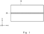
- Fig. 1 is a top view of a medium 10
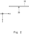
- Fig. 2 is a cross-sectional view of the sticking-type medium
- Fig. 3 is a cross-sectional view of the embedded-type medium 10.
- the medium 10 is a sheet or a plate with which a sensing optical fiber 20 is integrated.
- the medium 10 may be a sticking type in which the sensing optical fiber 20 is stuck to a surface of the medium 10.
- the medium 10 may be an embedded type in which the sensing optical fiber 20 is embedded in the medium 10.
- the medium 10 is arranged in a monitoring target 50 (see Fig. 5 and the like).
- the medium 10 may be only put on the monitoring target 50, or may be fixed to the monitoring target 50.
- a fixing portion for fixing the medium 10 to the monitoring target 50 may be, for example, an adhesive material, and, more specifically, may be an adhesive agent.
- the fixing portion is an adhesive agent
- the adhesive agent is applied to an adhesion surface of the medium 10, and the medium 10 is stuck to the monitoring target 50 by the adhesive agent.
- a method of fixing the medium 10 to the monitoring target 50 is not limited thereto.
- the optical fiber sensing system includes the medium 10 with which the sensing optical fiber 20 is integrated, and optical fiber sensing equipment 90. Moreover, the optical fiber sensing equipment 90 includes an optical fiber detection unit 30 and a state detection unit 40.
- the medium 10 is arranged in the monitoring target 50.
- the monitoring target 50 is, for example, an infrastructural structure such as a road, a railroad, a telephone pole, a tunnel, or a bridge, a building such as a floor or a wall, a piece of furniture such as a table, a chair, or a bed, or the like.
- the medium 10 may be arranged at each of a plurality of monitoring points, for one monitoring target 50.
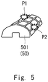
- Fig. 5 is an example of arranging the medium 10 at each of monitoring points P1 and P2 in two places of a tunnel 501 when the monitoring target 50 is the tunnel 501.
- the sensing optical fiber 20 is connected to the optical fiber detection unit 30.
- the sensing optical fiber 20 may be directly connected to the optical fiber detection unit 30, or may be indirectly connected to the optical fiber detection unit 30 via an existing optical fiber connected to the optical fiber detection unit 30.
- the existing optical fiber may be a communication optical fiber, or may be a sensing optical fiber previously laid for monitoring the monitoring target 50.
- Each of connection between the sensing optical fiber 20 and the optical fiber detection unit 30 and connection between the sensing optical fiber 20 and the existing optical fiber may be connection using a splice, or may be connection using a connector.
- the optical fiber detection unit 30 brings pulsed light into the sensing optical fiber 20. Moreover, the optical fiber detection unit 30 receives, from the sensing optical fiber 20, backward reflected light occurred at each transmission distance due to transmission of the pulsed light through the sensing optical fiber 20.
- the vibration, sound, temperature, stress, and the like are transmitted to the sensing optical fiber 20, and superimposed on backward reflected light transmitted by the sensing optical fiber 20.
- each of parameters of the vibration, sound, temperature, stress, and the like in the monitoring target 50 is superimposed on backward scattered light received by the optical fiber detection unit 30.
- a pattern contained in each parameter in the monitoring target 50 is a dynamically fluctuating fluctuation pattern, and differs according to a state of the monitoring target 50. For example, when a parameter is vibration, detecting transition of fluctuation in strength and weakness of the vibration, a vibration position, the number of vibrations, and the like enables defining a dynamic unique pattern of vibration occurred in the monitoring target 50.
- the optical fiber detection unit 30 detects a dynamic unique pattern of vibration in the monitoring target 50 according to a state or the like of the monitoring target 50, by use of, for example, a distributed vibration sensor and the like, based on backward scattered light received from the sensing optical fiber 20.
- Figs. 6 and 7 are examples of dynamic unique patterns of vibration when the monitoring target 50 is an infrastructural structure such as a tunnel, and each illustrate vibration data (frequency on a horizontal axis, and intensity (amplitude) on a vertical axis) after vibration data (time on a horizontal axis, and intensity (amplitude) on a vertical axis) of the infrastructural structure are subjected to fast Fourier transform (FFT).
- FFT fast Fourier transform
- the optical fiber detection unit 30 detects a dynamic unique pattern of vibration according to a deterioration state of the infrastructural structure, and this allows the state detection unit 40 at a subsequent stage to detect a deterioration state of the infrastructural structure.
- the optical fiber detection unit 30 may detect a multiplex unique pattern of the monitoring target 50 by detecting a dynamic unique pattern such as sound, temperature, and stress in the monitoring target 50 together, by use of a distributed acoustic sensor, a distributed temperature sensor, and the like. This allows the state detection unit 40 to detect a state of the monitoring target 50 with a higher degree of accuracy.
- the optical fiber detection unit 30 can also specify, based on, for example, a time difference between a time at which pulsed light is brought into the sensing optical fiber 20, and a time at which backward scattered light is received from the sensing optical fiber 20, a position where the backward scattered light occurs. Consequently, the optical fiber detection unit 30 is also capable of specifying a position of the monitoring target 50.
- the state detection unit 40 detects a state of the monitoring target 50, based on a unique pattern according to a state of the monitoring target 50 detected by the optical fiber detection unit 30. For example, in each of the above-described examples of Figs. 6 and 7 , a deterioration state of the monitoring target 50 is detected, based on a frequency at which a peak on vibration data occurs.
- the state detection unit 40 may detect a state of the monitoring target 50 by utilizing pattern matching. In other words, the state detection unit 40 may compare a unique pattern according to a state of the monitoring target 50 with a previously set matching pattern, and detect a specific state of the monitoring target 50 when the unique pattern matches the matching pattern. At this point, the state detection unit 40 may determine whether the unique pattern matches the matching pattern, by calculating a rate of matching the matching pattern with regard to the unique pattern according to a state of the monitoring target 50, and comparing the matching rate with a threshold value.
- the state detection unit 40 determines that a pattern matches when a matching rate is equal to or more than 70%, determines that a pattern does not match when a matching rate is equal to or less than 40%, and determines that there is a possibility of matching when a matching rate is between 40% and 70%.
- Matching rate Match/not match Equal to or more than 70% Match 40% to 70% There is a possibility of matching Equal to or less than 40% Not match
- a matching pattern may be learned by machine learning. Further, a matching pattern may be updated at any time by machine learning, or may be added.
- a state of the monitoring target 50 can be detected only by arranging the medium 10 in the monitoring target 50, and connecting the sensing optical fiber 20 integrated with the medium 10 to the optical fiber detection unit 30. This allows an optical fiber sensing system to be flexibly and easily built.
- the optical fiber detection unit 30 detects a pattern according to a state of the monitoring target 50, based on backward scattered light received from the sensing optical fiber 20, and the state detection unit 40 detects a state of the monitoring target 50, based on the detected pattern.
- the state detection unit 40 detects a state of the monitoring target 50, for example, not by detecting a state with such a broad criterion as whether vibration is large or small (e.g., specifying a state by largeness of vibration and a high number of vibrations) but by pattern-analyzing a change of a parameter dynamically (e.g., transition of a change in strength and weakness of vibration, and the like). This allows a state of the monitoring target 50 to be detected with a high degree of accuracy.
- optical fiber sensing system according to the present example embodiment is described below in more detail.
- the medium 10 may be a sheet 10A. Moreover, since the sheet 10A is small in thickness, it is preferable that the sheet 10A is a sticking type in which the sensing optical fiber 20 is stuck to a surface of the sheet 10A, but the sheet 10A may be an embedded type.
- Arrangement patterns of the sensing optical fiber 20 integrated with the sheet 10A may be various patterns.
- the sensing optical fiber 20 may have a linear arrangement pattern as illustrated in Fig. 8 , may have an arrangement pattern with a folded structure as illustrated in Fig. 9 , or may have an arrangement pattern with a helical structure as illustrated in Fig. 10 .
- the patterns with the folded structure and the helical structure illustrated in Figs. 9 and 10 improve density of the sensing optical fiber 20, and, therefore, enable improving detection sensitivity of the monitoring target 50.
- an arrangement pattern of the sensing optical fiber 20 may be used according to a shape of the monitoring target 50 and a pattern that is desired to be arranged in the monitoring target 50.
- a plurality of the sheets 10A may be combined and arranged in the monitoring target 50.
- the sensing optical fibers 20 in a plurality of the sheets 10A are connected in a one-stroke form. Connection of the sensing optical fibers 20 in the adjacent sheets 10A may be connection using a splice. Consequently, an optical fiber sensing system can be flexibly built without needing a complex construction.
- an arrangement pattern of the sensing optical fiber 20 in each of a plurality of the sheets 10A may be any arrangement pattern, and is not particularly limited.
- the sensing optical fiber 20 in each of all of a plurality of the sheets 10A may have the same arrangement pattern or may have a differing arrangement pattern, or some of the sensing optical fibers 20 may have the same arrangement pattern, and the other may have differing arrangement patterns.
- the medium 10 may be a plate 10B made of a material (e.g., concrete, resin, metal, and the like) having thickness. Moreover, since the plate 10B has thickness, it is preferable that the plate 10B is an embedded type in which the sensing optical fibers 20 is embedded in the plate 10B, but the plate 10B may be a sticking type.
- a material e.g., concrete, resin, metal, and the like
- a plurality of the plates 10B may be combined and arranged in the monitoring target 50 being a floor or the like of a monitoring target area.
- the sensing optical fibers 20 in a plurality of the plates 10B are connected in a one-stroke form. Connection of the sensing optical fibers 20 in the adjacent plates 10B may be connection using a connector. Consequently, an optical fiber sensing system can be flexibly built without needing a complex construction.
- an arrangement pattern of the sensing optical fiber 20 in each of a plurality of the plates 10B may be any arrangement pattern, and is not particularly limited.
- the sensing optical fiber 20 in each of all of a plurality of the plates 10B may have the same arrangement pattern or may have a differing arrangement pattern, or some of the sensing optical fibers 20 may have the same arrangement pattern, and the other may have differing arrangement patterns.
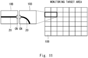
- Fig. 11 illustrates an example in which a plurality of the plates 10B are combined and arranged in the monitoring target 50 being a floor or the like of a monitoring target area.
- a plurality of the plates 10B are arranged in a lattice form in the monitoring target 50 being a floor or the like of a monitoring target area.
- the sensing optical fibers 20 in a plurality of the plates 10B are connected in a one-stroke form.
- an arrangement pattern of the sensing optical fiber 20 in each of a plurality of the plates 10B may be any arrangement pattern, as described above.
- the sensing optical fiber 20 has a linear arrangement pattern in one of the adjacent plates 10B
- the sensing optical fiber 20 has an arc-form arrangement pattern in the other of the adjacent plates 10B.
- the sensing optical fibers 20 of the adjacent plates 10B are connected by use of a connector CN.
- the monitoring target 50 is a chair or a bed
- a state of a person sitting on a chair or a person lying on a bed (a physical condition or an action of a person) can be detected by the optical fiber sensing system according to the present example embodiment.
- the sheet 10A as the medium 10 is described.
- the sheet 10A is stuck to the chair 502 in such a way that the sensing optical fibers 20 extend from a connector CN in two directions, one of the sensing optical fibers 20 is arranged in a seating surface portion of the chair 502, and the other sensing optical fiber 20 is arranged in a back plate portion of the chair 502.
- the connector CN is connected to the optical fiber detection unit 30.
- the optical fiber detection unit 30 is capable of detecting an occurrence position (a distance from the optical fiber detection unit 30) of backward scattered light as described above, it is necessary to specify which part of a body the occurrence position of the backward scattered light is in, in order to detect a state of a person.
- the state detection unit 40 previously holds a part information table associating a distance from the optical fiber detection unit 30 with part information indicating a part of a body being located at the distance, and specifies the part of the body by use of the part information table.
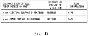
- Fig. 13 illustrates an example of a part information table.
- the part information table illustrated in Fig. 13 is a table in which a part of a body is specified on condition that vibration is present.
- the state detection unit 40 determines whether a person is sitting by presence or absence of vibration, and specifies a part of a body according to the part information table, when vibration is present.
- the part information table is a table generated based on a size of a standard body of a person sitting on the chair 502 by determining the size of the standard body from a size or type of the chair 502.
- the state detection unit 40 specifies a part to be an occurrence position of backward scattered light by use of the above-described part information table, and detects a state of a person sitting on the chair 502, based on a unique pattern occurred in the specified part.
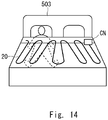
- the sheet 10A is stuck to the bed 503 in such a way that the sensing optical fiber 20 is arranged in a mattress of the bed 503.
- a connector CN is attached to an end of the sensing optical fiber 20, and the connector CN is connected to the optical fiber detection unit 30.
- the state detection unit 40 derives a distribution of an occurrence place of vibration occurred in the bed 503, and estimates, based on the distribution, a shape of a body of a person lying on the bed 503. Then, the state detection unit 40 generates a part information table as illustrated in Fig. 15 , based on an estimation result of the shape of the body of the person.
- the part information table illustrated in Fig. 15 is a table associating a distance from the optical fiber detection unit 30 with part information indicating a part of a body being located at the distance.
- the state detection unit 40 specifies a part to be an occurrence position of backward scattered light by use of the above-described part information table, and detects a state of a person lying on the bed 503, based on a unique pattern occurred in the specified part.
- the monitoring target 50 is an infrastructural structure such as a road, a railroad, a telephone pole, a tunnel, or a bridge
- a deterioration state of the infrastructural structure can be detected by the optical fiber sensing system according to the present example embodiment.
- the sheet 10A as the medium 10 is described.
- Fig. 5 described above is an example of sticking the sheet 10A to each of the monitoring points P1 and P2 in two places of the tunnel 501 when the monitoring target 50 is the tunnel 501, and detecting a deterioration state of the tunnel 501.
- the monitoring target 50 is a bridge 504
- the monitoring target 50 is a pipeline that transports fluid such as oil or natural gas
- outflow of the fluid from the pipeline can be detected by the optical fiber sensing system according to the present example embodiment.
- the sheet 10A as the medium 10 is described.
- the sheet 10A is stuck to an inner surface of the pipeline 505 in such a way that the sensing optical fiber 20 is arranged in the inner surface of the pipeline 505 along the pipeline 505.
- the state detection unit 40 monitors whether a local temperature change is detected in the sensing optical fiber 20, and determines that outflow of fluid from the pipeline 505 has occurred when a local temperature change is detected. Moreover, since the optical fiber detection unit 30 can specify a position where a local temperature change occurs (a distance from the optical fiber detection unit 30), the state detection unit 40 can specify, in a short period of time, a position where fluid has flowed out.
- the monitoring target 50 is a room
- a fire having a possibility of occurring in the room can be detected early by the optical fiber sensing system according to the present example embodiment.
- an example of using the sheet 10A as the medium 10 is described.
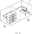
- the monitoring targets 50 are two rooms including a server room 506-1 and an office room 506-2.
- the sheet 10A is stuck in such a way that the sensing optical fiber 20 is arranged over the two rooms including the server room 506-1 and the office room 506-2.
- the sensing optical fiber 20 is arranged on walls of the two rooms, a server in the server room 506-1, and a computer in the office room 506-2 in Fig. 18 , the present disclosure is not limited thereto.
- the sensing optical fiber 20 may be arranged on ceilings of the two rooms.
- the state detection unit 40 monitors a temperature detected in the sensing optical fiber 20, and determines that there is a possibility that a fire occurs when a temperature higher than a normal temperature is detected.
- the optical fiber detection unit 30 is capable of specifying a position (a distance from the optical fiber detection unit 30) where a temperature higher than a normal temperature is detected.
- the state detection unit 40 can specify a room where there is a possibility that a fire occurs, by previously holding a room information table associating a distance from the optical fiber detection unit 30 with a room being located at the distance.
- the state detection unit 40 may notify insides of the server room 506-1 and the office room 506-2, a monitoring center, and the like of the fact as an alarm.
- unauthorized invasion detection is an important security task.
- unauthorized invasion detection is needed in a scene such as protection of an offshore platform and a generation facility.
- the monitoring target 50 is an important facility
- unauthorized invasion into the important facility can be detected by the optical fiber sensing system according to the present example embodiment.
- the monitoring target 50 is an airport 507.
- the sensing optical fiber 20 is arranged by sticking the sheet 10A to a fence 508 surrounding the airport 507, and vibration and sound occurred in the fence 508 and therearound are detected by the sensing optical fiber 20.
- the state detection unit 40 detects, for example, the following predetermined events, based on unique patterns of vibration and sound occurred in the fence 508 and therearound.
- the state detection unit 40 determines that the event is unauthorized invasion into the airport 507. Moreover, when determining that the event is unauthorized invasion into the airport 507, the state detection unit 40 may notify a monitoring center 60 of the fact as an alarm.
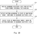
- FIG. 20 illustrates an operation after the medium 10 is arranged in the monitoring target 50, and the sensing optical fiber 20 integrated with the medium 10 is connected to the optical fiber detection unit 30.
- the optical fiber detection unit 30 brings pulsed light into the sensing optical fiber 20 integrated with the medium 10 arranged in the monitoring target 50, and receives backward scattered light from the sensing optical fiber 20 (step S11).
- the optical fiber detection unit 30 detects a pattern according to a state of the monitoring target 50, contained in the received backward scattered light (step S12).
- the state detection unit 40 detects a state of the monitoring target 50, based on the pattern contained in the backward scattered light (step S13).
- the state detection unit 40 may detect a state of the monitoring target 50 by utilizing pattern matching. In other words, the state detection unit 40 may compare a unique pattern according to a state of the monitoring target 50 with a matching pattern, and detect a specific state of the monitoring target 50 when the unique pattern matches the matching pattern.
- the sensing optical fiber 20 integrated with the medium 10 arranged in the monitoring target 50 is connected to the optical fiber detection unit 30, the optical fiber detection unit 30 detects a pattern according to a state of the monitoring target 50, contained in backward scattered light (an optical signal) received from the sensing optical fiber 20, and the state detection unit 40 detects a state of the monitoring target 50, based on the pattern contained in the backward scattered light.
- a state of the monitoring target 50 can be detected only by arranging the medium 10 in the monitoring target 50, and connecting the sensing optical fiber 20 integrated with the medium 10 to the optical fiber detection unit 30. This allows an optical fiber sensing system to be flexibly and easily built.
- the state detection unit 40 detects a state of the monitoring target 50, based on a pattern according to a state of the monitoring target 50, contained in backward scattered light.
- the state detection unit 40 detects a state of the monitoring target 50, for example, not by detecting a state with such a broad criterion as whether vibration is large or small (e.g., specifying a state by largeness of vibration and a high number of vibrations) but by pattern-analyzing a change of a parameter dynamically (e.g., transition of a change in strength and weakness of vibration, and the like). This allows a state of the monitoring target 50 to be detected with a high degree of accuracy.
- the optical fiber sensing equipment 90 includes the optical fiber detection unit 30 and the state detection unit 40 in the above-described example embodiment, the present disclosure is not limited thereto.
- the optical fiber detection unit 30 and the state detection unit 40 may be each achieved by a separate device.
- the present disclosure is also capable of achieving any processing of the optical fiber detection unit 30 and the state detection unit 40 by reading and executing, with a processor such as a central processing unit (CPU), a computer program stored in a memory such as a random access memory (RAM) or a read only memory (ROM).
- a processor such as a central processing unit (CPU)
- CPU central processing unit
- RAM random access memory
- ROM read only memory
- the above-described program can be stored by use of various types of non-transitory computer-readable media, and supplied to a computer.
- the non-transitory computer-readable media include various types of tangible storage media. Examples of the non-transitory computer-readable media include a magnetic recording medium (e.g., a flexible disk, a magnetic tape, and a hard disk drive), a magneto-optical recording medium (e.g., a magneto-optical disk), a compact disc-read only memory (CD-ROM), a CD-recordable (CD-R), a CD-rewritable (CD-R/W), and a semiconductor memory (e.g., a mask ROM, a programmable ROM (PROM), an erasable PROM (EPROM), a flash ROM, and a random access memory (RAM).
- a magnetic recording medium e.g., a flexible disk, a magnetic tape, and a hard disk drive
- a magneto-optical recording medium e
- the above-described program may be supplied to a computer by various types of transitory computer readable media.
- Examples of the transitory computer readable media include an electric signal, an optical signal, and an electromagnetic wave.
- the transitory computer readable medium can supply a program to a computer via a wired communication path such as an electric wire or an optical fiber, or a wireless communication path.
Landscapes
- Physics & Mathematics (AREA)
- General Physics & Mathematics (AREA)
- Engineering & Computer Science (AREA)
- Aviation & Aerospace Engineering (AREA)
- Chemical & Material Sciences (AREA)
- Analytical Chemistry (AREA)
- Electromagnetism (AREA)
- Geophysics And Detection Of Objects (AREA)
- Optical Transform (AREA)
- Measurement Of Mechanical Vibrations Or Ultrasonic Waves (AREA)
- Burglar Alarm Systems (AREA)
Abstract
Description
- The present disclosure relates to an optical fiber sensing system.
- There is a technique being referred as optical fiber sensing using an optical fiber as a sensor. The optical fiber sensing is utilized for detecting a state or the like of a monitoring target.
- Herein, when a monitoring target is an infrastructural structure such as a road, a railroad, a telephone pole, a tunnel, or a bridge, an existing optical fiber (e.g., an existing communication optical fiber) may be laid in the monitoring target. In this case, detection of a state or the like of the monitoring target is possible by making use of the existing optical fiber as a sensor.
- However, in recent years, in an optical fiber sensing system, monitoring targets have been diversified, and an existing optical fiber is not necessarily laid near a monitoring target.
- Thus, recently, flexibly and easily building an optical fiber sensing system has been required.
- For example, a technique described in Patent Literature 1 can be cited as a technique for flexibly and easily building an optical fiber sensing system. The technique described in Patent Literature 1 places, in a monitoring area, a person detection sensor including an optical fiber fixed onto a sheet surface. When there is a person on a floor surface of the monitoring area, the person detection sensor is deformed, bending occurs at an optical fiber, and, as a result, power of an optical signal transmitted through the optical fiber fluctuates. The technique described in Patent Literature 1 detects presence or absence of a person in the monitoring area by detecting the fluctuation of the power of the optical signal.
- [Patent Literature 1]
Japanese Unexamined Patent Application Publication No. 2005-184772 - However, a technique described in Patent Literature 1 performs detection of presence or absence of a person by monitoring power fluctuation of an optical signal when strong stress is applied to an optical fiber.
- Thus, there is a problem that, in a monitoring area, such an extreme state that strong stress is applied to an optical fiber can be detected, but detection of such a state as to hardly influence stress on an optical fiber is difficult.
- Accordingly, an object of the present disclosure is to provide an optical fiber sensing system that solves the above-described problem, and can detect a state of a monitoring target with a high degree of accuracy.
- An optical fiber sensing system according to one aspect includes:
- a sensing optical fiber;
- a medium that is integrated with the sensing optical fiber, and is arranged in a monitoring target;
- an optical fiber detection unit that is connected to the sensing optical fiber integrated with the medium, the optical fiber detection unit is configured to receive an optical signal from the sensing optical fiber, and detect a pattern according to a state of the monitoring target, contained in the optical signal; and
- a state detection unit configured to detect a state of the monitoring target, based on the pattern contained in the optical signal.
- According to the above-described aspect, an advantageous effect can be acquired in which an optical fiber sensing system that can detect a state of a monitoring target with a high degree of accuracy can be provided.
-
-
Fig. 1 is a top view illustrating a configuration example of a medium according to an example embodiment. -
Fig. 2 is a cross-sectional view illustrating a configuration example of a sticking-type medium according to the example embodiment. -
Fig. 3 is a cross-sectional view illustrating a configuration example of an embedded-type medium according to the example embodiment. -
Fig. 4 is a diagram illustrating a configuration example of an optical fiber sensing system according to the example embodiment. -
Fig. 5 is a diagram illustrating an example of a monitoring point of a monitoring target in which a medium according to the example embodiment is arranged. -
Fig. 6 is a diagram illustrating an example of a unique pattern according to a deterioration state of a monitoring target. -
Fig. 7 is a diagram illustrating another example of a unique pattern according to a deterioration state of a monitoring target. -
Fig. 8 is a diagram illustrating an example of an arrangement pattern of a sensing optical fiber in a medium (sheet) according to the example embodiment. -
Fig. 9 is a diagram illustrating another example of an arrangement pattern of a sensing optical fiber in a medium (sheet) according to the example embodiment. -
Fig. 10 is a diagram illustrating still another example of an arrangement pattern of a sensing optical fiber in a medium (sheet) according to the example embodiment. -
Fig. 11 is a diagram illustrating an example in which a plurality of media (plates) according to the example embodiment are combined and arranged in a floor or the like of a monitoring target area. -
Fig. 12 is a diagram illustrating an example of detecting a state of a person sitting on a chair, in the optical fiber sensing system according to the example embodiment. -
Fig. 13 is a diagram illustrating an example of a part information table used in the example ofFig. 12 . -
Fig. 14 is a diagram illustrating an example of detecting a state of a person lying on a bed, in the optical fiber sensing system according to the example embodiment. -
Fig. 15 is a diagram illustrating an example of a part information table used in the example ofFig. 14 . -
Fig. 16 is a diagram illustrating an example of detecting a deterioration state of a bridge, in the optical fiber sensing system according to the example embodiment. -
Fig. 17 is a diagram illustrating an example of detecting outflow of fluid from a pipeline, in the optical fiber sensing system according to the example embodiment. -
Fig. 18 is a diagram illustrating an example of detecting a fire early, in the optical fiber sensing system according to the example embodiment. -
Fig. 19 is a diagram illustrating an example of detecting unauthorized invasion into an airport, in the optical fiber sensing system according to the example embodiment. -
Fig. 20 is a flow diagram illustrating an example of an operation flow of the optical fiber sensing system according to the example embodiment. - Hereinafter, an example embodiment of the present disclosure is described with reference to the drawings.
- First, a configuration of a
medium 10 used in an optical fiber sensing system according to the present example embodiment is described with reference toFigs. 1 to 3 .Fig. 1 is a top view of amedium 10,Fig. 2 is a cross-sectional view of the sticking-type medium 10, andFig. 3 is a cross-sectional view of the embedded-type medium 10. - As illustrated in
Fig. 1 , themedium 10 is a sheet or a plate with which a sensingoptical fiber 20 is integrated. - Moreover, as illustrated in
Fig. 2 , themedium 10 may be a sticking type in which the sensingoptical fiber 20 is stuck to a surface of themedium 10. Alternatively, as illustrated inFig. 3 , themedium 10 may be an embedded type in which the sensingoptical fiber 20 is embedded in themedium 10. - Moreover, the
medium 10 is arranged in a monitoring target 50 (seeFig. 5 and the like). Themedium 10 may be only put on themonitoring target 50, or may be fixed to themonitoring target 50. A fixing portion for fixing themedium 10 to themonitoring target 50 may be, for example, an adhesive material, and, more specifically, may be an adhesive agent. For example, when the fixing portion is an adhesive agent, the adhesive agent is applied to an adhesion surface of themedium 10, and themedium 10 is stuck to themonitoring target 50 by the adhesive agent. However, a method of fixing themedium 10 to themonitoring target 50 is not limited thereto. - Further, a configuration of the optical fiber sensing system according to the present example embodiment is described with reference to
Fig. 4 . - As illustrated in
Fig. 4 , the optical fiber sensing system according to the present example embodiment includes themedium 10 with which the sensingoptical fiber 20 is integrated, and opticalfiber sensing equipment 90. Moreover, the opticalfiber sensing equipment 90 includes an opticalfiber detection unit 30 and astate detection unit 40. - The
medium 10 is arranged in themonitoring target 50. Themonitoring target 50 is, for example, an infrastructural structure such as a road, a railroad, a telephone pole, a tunnel, or a bridge, a building such as a floor or a wall, a piece of furniture such as a table, a chair, or a bed, or the like. Moreover, since vibration or the like differs at each position of themonitoring target 50, the medium 10 may be arranged at each of a plurality of monitoring points, for onemonitoring target 50.Fig. 5 is an example of arranging the medium 10 at each of monitoring points P1 and P2 in two places of atunnel 501 when themonitoring target 50 is thetunnel 501. - The sensing
optical fiber 20 is connected to the opticalfiber detection unit 30. The sensingoptical fiber 20 may be directly connected to the opticalfiber detection unit 30, or may be indirectly connected to the opticalfiber detection unit 30 via an existing optical fiber connected to the opticalfiber detection unit 30. The existing optical fiber may be a communication optical fiber, or may be a sensing optical fiber previously laid for monitoring themonitoring target 50. Each of connection between the sensingoptical fiber 20 and the opticalfiber detection unit 30 and connection between the sensingoptical fiber 20 and the existing optical fiber may be connection using a splice, or may be connection using a connector. - The optical
fiber detection unit 30 brings pulsed light into the sensingoptical fiber 20. Moreover, the opticalfiber detection unit 30 receives, from the sensingoptical fiber 20, backward reflected light occurred at each transmission distance due to transmission of the pulsed light through the sensingoptical fiber 20. - Herein, when vibration, sound, temperature, stress, and the like occur in the
monitoring target 50, the vibration, sound, temperature, stress, and the like are transmitted to the sensingoptical fiber 20, and superimposed on backward reflected light transmitted by the sensingoptical fiber 20. - Thus, each of parameters of the vibration, sound, temperature, stress, and the like in the
monitoring target 50 is superimposed on backward scattered light received by the opticalfiber detection unit 30. At this point, a pattern contained in each parameter in themonitoring target 50 is a dynamically fluctuating fluctuation pattern, and differs according to a state of themonitoring target 50. For example, when a parameter is vibration, detecting transition of fluctuation in strength and weakness of the vibration, a vibration position, the number of vibrations, and the like enables defining a dynamic unique pattern of vibration occurred in themonitoring target 50. - Thus, the optical
fiber detection unit 30 detects a dynamic unique pattern of vibration in themonitoring target 50 according to a state or the like of themonitoring target 50, by use of, for example, a distributed vibration sensor and the like, based on backward scattered light received from the sensingoptical fiber 20.Figs. 6 and7 are examples of dynamic unique patterns of vibration when themonitoring target 50 is an infrastructural structure such as a tunnel, and each illustrate vibration data (frequency on a horizontal axis, and intensity (amplitude) on a vertical axis) after vibration data (time on a horizontal axis, and intensity (amplitude) on a vertical axis) of the infrastructural structure are subjected to fast Fourier transform (FFT). In the vibration data illustrated inFigs. 6 and7 , a peak of intensity occurs, and a frequency at which the peak occurs differs according to a deterioration state of the infrastructural structure. Thus, the opticalfiber detection unit 30 detects a dynamic unique pattern of vibration according to a deterioration state of the infrastructural structure, and this allows thestate detection unit 40 at a subsequent stage to detect a deterioration state of the infrastructural structure. - Moreover, the optical
fiber detection unit 30 may detect a multiplex unique pattern of themonitoring target 50 by detecting a dynamic unique pattern such as sound, temperature, and stress in themonitoring target 50 together, by use of a distributed acoustic sensor, a distributed temperature sensor, and the like. This allows thestate detection unit 40 to detect a state of themonitoring target 50 with a higher degree of accuracy. - Moreover, the optical
fiber detection unit 30 can also specify, based on, for example, a time difference between a time at which pulsed light is brought into the sensingoptical fiber 20, and a time at which backward scattered light is received from the sensingoptical fiber 20, a position where the backward scattered light occurs. Consequently, the opticalfiber detection unit 30 is also capable of specifying a position of themonitoring target 50. - The
state detection unit 40 detects a state of themonitoring target 50, based on a unique pattern according to a state of themonitoring target 50 detected by the opticalfiber detection unit 30. For example, in each of the above-described examples ofFigs. 6 and7 , a deterioration state of themonitoring target 50 is detected, based on a frequency at which a peak on vibration data occurs. - Moreover, the
state detection unit 40 may detect a state of themonitoring target 50 by utilizing pattern matching. In other words, thestate detection unit 40 may compare a unique pattern according to a state of themonitoring target 50 with a previously set matching pattern, and detect a specific state of themonitoring target 50 when the unique pattern matches the matching pattern. At this point, thestate detection unit 40 may determine whether the unique pattern matches the matching pattern, by calculating a rate of matching the matching pattern with regard to the unique pattern according to a state of themonitoring target 50, and comparing the matching rate with a threshold value. For example, in an example of a table 1, thestate detection unit 40 determines that a pattern matches when a matching rate is equal to or more than 70%, determines that a pattern does not match when a matching rate is equal to or less than 40%, and determines that there is a possibility of matching when a matching rate is between 40% and 70%.[Table 1] Matching rate Match/not match Equal to or more than 70 % Match 40% to 70% There is a possibility of matching Equal to or less than 40% Not match - Moreover, a matching pattern may be learned by machine learning. Further, a matching pattern may be updated at any time by machine learning, or may be added.
- As described above, in the optical fiber sensing system according to the present example embodiment, a state of the
monitoring target 50 can be detected only by arranging the medium 10 in themonitoring target 50, and connecting the sensingoptical fiber 20 integrated with the medium 10 to the opticalfiber detection unit 30. This allows an optical fiber sensing system to be flexibly and easily built. - Moreover, in the optical fiber sensing system according to the present example embodiment, the optical
fiber detection unit 30 detects a pattern according to a state of themonitoring target 50, based on backward scattered light received from the sensingoptical fiber 20, and thestate detection unit 40 detects a state of themonitoring target 50, based on the detected pattern. In other words, thestate detection unit 40 detects a state of themonitoring target 50, for example, not by detecting a state with such a broad criterion as whether vibration is large or small (e.g., specifying a state by largeness of vibration and a high number of vibrations) but by pattern-analyzing a change of a parameter dynamically (e.g., transition of a change in strength and weakness of vibration, and the like). This allows a state of themonitoring target 50 to be detected with a high degree of accuracy. - The optical fiber sensing system according to the present example embodiment is described below in more detail.
- The medium 10 may be a
sheet 10A. Moreover, since thesheet 10A is small in thickness, it is preferable that thesheet 10A is a sticking type in which the sensingoptical fiber 20 is stuck to a surface of thesheet 10A, but thesheet 10A may be an embedded type. - Arrangement patterns of the sensing
optical fiber 20 integrated with thesheet 10A may be various patterns. For example, the sensingoptical fiber 20 may have a linear arrangement pattern as illustrated inFig. 8 , may have an arrangement pattern with a folded structure as illustrated inFig. 9 , or may have an arrangement pattern with a helical structure as illustrated inFig. 10 . Among the patterns, the patterns with the folded structure and the helical structure illustrated inFigs. 9 and10 improve density of the sensingoptical fiber 20, and, therefore, enable improving detection sensitivity of themonitoring target 50. Moreover, an arrangement pattern of the sensingoptical fiber 20 may be used according to a shape of themonitoring target 50 and a pattern that is desired to be arranged in themonitoring target 50. - Moreover, a plurality of the
sheets 10A may be combined and arranged in themonitoring target 50. In this case, the sensingoptical fibers 20 in a plurality of thesheets 10A are connected in a one-stroke form. Connection of the sensingoptical fibers 20 in theadjacent sheets 10A may be connection using a splice. Consequently, an optical fiber sensing system can be flexibly built without needing a complex construction. In this case, an arrangement pattern of the sensingoptical fiber 20 in each of a plurality of thesheets 10A may be any arrangement pattern, and is not particularly limited. For example, the sensingoptical fiber 20 in each of all of a plurality of thesheets 10A may have the same arrangement pattern or may have a differing arrangement pattern, or some of the sensingoptical fibers 20 may have the same arrangement pattern, and the other may have differing arrangement patterns. - The medium 10 may be a
plate 10B made of a material (e.g., concrete, resin, metal, and the like) having thickness. Moreover, since theplate 10B has thickness, it is preferable that theplate 10B is an embedded type in which the sensingoptical fibers 20 is embedded in theplate 10B, but theplate 10B may be a sticking type. - Moreover, a plurality of the
plates 10B may be combined and arranged in themonitoring target 50 being a floor or the like of a monitoring target area. In this case, the sensingoptical fibers 20 in a plurality of theplates 10B are connected in a one-stroke form. Connection of the sensingoptical fibers 20 in theadjacent plates 10B may be connection using a connector. Consequently, an optical fiber sensing system can be flexibly built without needing a complex construction. In this case, an arrangement pattern of the sensingoptical fiber 20 in each of a plurality of theplates 10B may be any arrangement pattern, and is not particularly limited. For example, the sensingoptical fiber 20 in each of all of a plurality of theplates 10B may have the same arrangement pattern or may have a differing arrangement pattern, or some of the sensingoptical fibers 20 may have the same arrangement pattern, and the other may have differing arrangement patterns. -
Fig. 11 illustrates an example in which a plurality of theplates 10B are combined and arranged in themonitoring target 50 being a floor or the like of a monitoring target area. - In the example of
Fig. 11 , a plurality of theplates 10B are arranged in a lattice form in themonitoring target 50 being a floor or the like of a monitoring target area. In this case, the sensingoptical fibers 20 in a plurality of theplates 10B are connected in a one-stroke form. Moreover, an arrangement pattern of the sensingoptical fiber 20 in each of a plurality of theplates 10B may be any arrangement pattern, as described above. For example, in the example ofFig. 11 , while the sensingoptical fiber 20 has a linear arrangement pattern in one of theadjacent plates 10B, the sensingoptical fiber 20 has an arc-form arrangement pattern in the other of theadjacent plates 10B. Moreover, the sensingoptical fibers 20 of theadjacent plates 10B are connected by use of a connector CN. - Further, an application achievable by the optical fiber sensing system according to the present example embodiment is described.
- For example, when the
monitoring target 50 is a chair or a bed, a state of a person sitting on a chair or a person lying on a bed (a physical condition or an action of a person) can be detected by the optical fiber sensing system according to the present example embodiment. Herein, an example of using thesheet 10A as the medium 10 is described. - First, an example of detecting a state of a person sitting on a
chair 502 when themonitoring target 50 is thechair 502 is described with reference toFig. 12 . - In the example of
Fig. 12 , thesheet 10A is stuck to thechair 502 in such a way that the sensingoptical fibers 20 extend from a connector CN in two directions, one of the sensingoptical fibers 20 is arranged in a seating surface portion of thechair 502, and the other sensingoptical fiber 20 is arranged in a back plate portion of thechair 502. The connector CN is connected to the opticalfiber detection unit 30. - Herein, while the optical
fiber detection unit 30 is capable of detecting an occurrence position (a distance from the optical fiber detection unit 30) of backward scattered light as described above, it is necessary to specify which part of a body the occurrence position of the backward scattered light is in, in order to detect a state of a person. - Thus, the
state detection unit 40 previously holds a part information table associating a distance from the opticalfiber detection unit 30 with part information indicating a part of a body being located at the distance, and specifies the part of the body by use of the part information table.Fig. 13 illustrates an example of a part information table. Moreover, the part information table illustrated inFig. 13 is a table in which a part of a body is specified on condition that vibration is present. In other words, thestate detection unit 40 determines whether a person is sitting by presence or absence of vibration, and specifies a part of a body according to the part information table, when vibration is present. Note that, it is preferable that the part information table is a table generated based on a size of a standard body of a person sitting on thechair 502 by determining the size of the standard body from a size or type of thechair 502. - The
state detection unit 40 specifies a part to be an occurrence position of backward scattered light by use of the above-described part information table, and detects a state of a person sitting on thechair 502, based on a unique pattern occurred in the specified part. - Further, an example of detecting a state of a person lying on a
bed 503 when themonitoring target 50 is thebed 503 is described with reference toFig. 14 . - In the example of
Fig. 14 , thesheet 10A is stuck to thebed 503 in such a way that the sensingoptical fiber 20 is arranged in a mattress of thebed 503. A connector CN is attached to an end of the sensingoptical fiber 20, and the connector CN is connected to the opticalfiber detection unit 30. - Herein, in a case of the
bed 503 as well as in thechair 502, it is necessary to specify which part of a body an occurrence position of backward scattered light is in, in order to detect a state of a person. - When a person lies on the
bed 503, vibration along a body of the person occurs in thebed 503. - Thus, the
state detection unit 40 derives a distribution of an occurrence place of vibration occurred in thebed 503, and estimates, based on the distribution, a shape of a body of a person lying on thebed 503. Then, thestate detection unit 40 generates a part information table as illustrated inFig. 15 , based on an estimation result of the shape of the body of the person. The part information table illustrated inFig. 15 is a table associating a distance from the opticalfiber detection unit 30 with part information indicating a part of a body being located at the distance. - The
state detection unit 40 specifies a part to be an occurrence position of backward scattered light by use of the above-described part information table, and detects a state of a person lying on thebed 503, based on a unique pattern occurred in the specified part. - Moreover, when the
monitoring target 50 is an infrastructural structure such as a road, a railroad, a telephone pole, a tunnel, or a bridge, a deterioration state of the infrastructural structure can be detected by the optical fiber sensing system according to the present example embodiment. Herein, an example of using thesheet 10A as the medium 10 is described. -
Fig. 5 described above is an example of sticking thesheet 10A to each of the monitoring points P1 and P2 in two places of thetunnel 501 when themonitoring target 50 is thetunnel 501, and detecting a deterioration state of thetunnel 501. - In addition, for example, as illustrated in
Fig. 16 , when themonitoring target 50 is abridge 504, it is also possible to stick thesheet 10A to the monitoring point P1 of thebridge 504, and detect a deterioration state of thebridge 504. - Note that, although it is possible to detect a deterioration state of the infrastructural structure by use of, for example, each of the methods described with
Figs. 6 and7 , the present disclosure is not limited to the example. - Moreover, when the
monitoring target 50 is a pipeline that transports fluid such as oil or natural gas, outflow of the fluid from the pipeline can be detected by the optical fiber sensing system according to the present example embodiment. Herein, an example of using thesheet 10A as the medium 10 is described. - For example, as illustrated in
Fig. 17 , when themonitoring target 50 is apipeline 505, thesheet 10A is stuck to an inner surface of thepipeline 505 in such a way that the sensingoptical fiber 20 is arranged in the inner surface of thepipeline 505 along thepipeline 505. - When fluid flows out from the
pipeline 505, a local temperature change occurs. Thus, thestate detection unit 40 monitors whether a local temperature change is detected in the sensingoptical fiber 20, and determines that outflow of fluid from thepipeline 505 has occurred when a local temperature change is detected. Moreover, since the opticalfiber detection unit 30 can specify a position where a local temperature change occurs (a distance from the optical fiber detection unit 30), thestate detection unit 40 can specify, in a short period of time, a position where fluid has flowed out. - Moreover, when the
monitoring target 50 is a room, a fire having a possibility of occurring in the room can be detected early by the optical fiber sensing system according to the present example embodiment. Herein, an example of using thesheet 10A as the medium 10 is described. - For example, as illustrated in
Fig. 18 , it is assumed that the monitoring targets 50 are two rooms including a server room 506-1 and an office room 506-2. In this case, thesheet 10A is stuck in such a way that the sensingoptical fiber 20 is arranged over the two rooms including the server room 506-1 and the office room 506-2. Note that, although the sensingoptical fiber 20 is arranged on walls of the two rooms, a server in the server room 506-1, and a computer in the office room 506-2 inFig. 18 , the present disclosure is not limited thereto. The sensingoptical fiber 20 may be arranged on ceilings of the two rooms. - The
state detection unit 40 monitors a temperature detected in the sensingoptical fiber 20, and determines that there is a possibility that a fire occurs when a temperature higher than a normal temperature is detected. Moreover, the opticalfiber detection unit 30 is capable of specifying a position (a distance from the optical fiber detection unit 30) where a temperature higher than a normal temperature is detected. Thus, thestate detection unit 40 can specify a room where there is a possibility that a fire occurs, by previously holding a room information table associating a distance from the opticalfiber detection unit 30 with a room being located at the distance. - Note that, when determining that there is a possibility that a fire occurs, the
state detection unit 40 may notify insides of the server room 506-1 and the office room 506-2, a monitoring center, and the like of the fact as an alarm. - In protection of a building and an outer periphery thereof, monitoring of a battlefield and a border, and the like, unauthorized invasion detection is an important security task. Moreover, in an oil industry and a gas industry as well, unauthorized invasion detection is needed in a scene such as protection of an offshore platform and a generation facility.
- When the
monitoring target 50 is an important facility, unauthorized invasion into the important facility can be detected by the optical fiber sensing system according to the present example embodiment. - For example, when an important facility is an airport, a port, a power plant, a border, or the like on ground, sticking the
sheet 10A to a fence, or embedding thesheet 10A or theplate 10B in ground around the fence can be conceived. - Moreover, when an important facility is an underground facility, a tunnel, or the like in ground, sticking the
sheet 10A to inside of a structure, or embedding thesheet 10A or theplate 10B in ground around the structure can be conceived. - Moreover, when an important facility is an offshore oil platform, a submarine cable landing station, or the like under water, sticking the
sheet 10A to a fence or a facility, or embedding thesheet 10A or theplate 10B in ground around the fence or the facility can be conceived. - For example, as illustrated in
Fig. 19 , it is assumed that themonitoring target 50 is anairport 507. In this case, the sensingoptical fiber 20 is arranged by sticking thesheet 10A to afence 508 surrounding theairport 507, and vibration and sound occurred in thefence 508 and therearound are detected by the sensingoptical fiber 20. - The
state detection unit 40 detects, for example, the following predetermined events, based on unique patterns of vibration and sound occurred in thefence 508 and therearound. - (1) A person grasps and shakes the
fence 508 - (2) A person hits the
fence 508 - (3) A person climbs up the
fence 508 - (4) A person places a ladder against the
fence 508, and climbs the ladder - (5) A person prowls around the
fence 508 - (6) A person digs around the
fence 508 - When detecting a predetermined event as described above, the
state detection unit 40 determines that the event is unauthorized invasion into theairport 507. Moreover, when determining that the event is unauthorized invasion into theairport 507, thestate detection unit 40 may notify amonitoring center 60 of the fact as an alarm. - An operation flow of a schematic operation of the optical fiber sensing system according to the present example embodiment is described below with reference to
Fig. 20 . Note that,Fig. 20 illustrates an operation after the medium 10 is arranged in themonitoring target 50, and the sensingoptical fiber 20 integrated with the medium 10 is connected to the opticalfiber detection unit 30. - As illustrated in
Fig. 20 , first, the opticalfiber detection unit 30 brings pulsed light into the sensingoptical fiber 20 integrated with the medium 10 arranged in themonitoring target 50, and receives backward scattered light from the sensing optical fiber 20 (step S11). - Further, the optical
fiber detection unit 30 detects a pattern according to a state of themonitoring target 50, contained in the received backward scattered light (step S12). - Thereafter, the
state detection unit 40 detects a state of themonitoring target 50, based on the pattern contained in the backward scattered light (step S13). At this point, as described above, thestate detection unit 40 may detect a state of themonitoring target 50 by utilizing pattern matching. In other words, thestate detection unit 40 may compare a unique pattern according to a state of themonitoring target 50 with a matching pattern, and detect a specific state of themonitoring target 50 when the unique pattern matches the matching pattern. - As described above, according to the present example embodiment, the sensing
optical fiber 20 integrated with the medium 10 arranged in themonitoring target 50 is connected to the opticalfiber detection unit 30, the opticalfiber detection unit 30 detects a pattern according to a state of themonitoring target 50, contained in backward scattered light (an optical signal) received from the sensingoptical fiber 20, and thestate detection unit 40 detects a state of themonitoring target 50, based on the pattern contained in the backward scattered light. - Thus, a state of the
monitoring target 50 can be detected only by arranging the medium 10 in themonitoring target 50, and connecting the sensingoptical fiber 20 integrated with the medium 10 to the opticalfiber detection unit 30. This allows an optical fiber sensing system to be flexibly and easily built. - Moreover, according to the present example embodiment, the
state detection unit 40 detects a state of themonitoring target 50, based on a pattern according to a state of themonitoring target 50, contained in backward scattered light. In other words, thestate detection unit 40 detects a state of themonitoring target 50, for example, not by detecting a state with such a broad criterion as whether vibration is large or small (e.g., specifying a state by largeness of vibration and a high number of vibrations) but by pattern-analyzing a change of a parameter dynamically (e.g., transition of a change in strength and weakness of vibration, and the like). This allows a state of themonitoring target 50 to be detected with a high degree of accuracy. - While the present disclosure has been described above with reference to the example embodiment, the present disclosure is not limited to the above-described example embodiment. Various changes that may be understood by a person skilled in the art can be made to a configuration and details according to the present disclosure within the scope of the present disclosure.
- For example, although the optical
fiber sensing equipment 90 includes the opticalfiber detection unit 30 and thestate detection unit 40 in the above-described example embodiment, the present disclosure is not limited thereto. The opticalfiber detection unit 30 and thestate detection unit 40 may be each achieved by a separate device. - Moreover, the present disclosure is also capable of achieving any processing of the optical
fiber detection unit 30 and thestate detection unit 40 by reading and executing, with a processor such as a central processing unit (CPU), a computer program stored in a memory such as a random access memory (RAM) or a read only memory (ROM). - The above-described program can be stored by use of various types of non-transitory computer-readable media, and supplied to a computer. The non-transitory computer-readable media include various types of tangible storage media. Examples of the non-transitory computer-readable media include a magnetic recording medium (e.g., a flexible disk, a magnetic tape, and a hard disk drive), a magneto-optical recording medium (e.g., a magneto-optical disk), a compact disc-read only memory (CD-ROM), a CD-recordable (CD-R), a CD-rewritable (CD-R/W), and a semiconductor memory (e.g., a mask ROM, a programmable ROM (PROM), an erasable PROM (EPROM), a flash ROM, and a random access memory (RAM). Moreover, the above-described program may be supplied to a computer by various types of transitory computer readable media. Examples of the transitory computer readable media include an electric signal, an optical signal, and an electromagnetic wave. The transitory computer readable medium can supply a program to a computer via a wired communication path such as an electric wire or an optical fiber, or a wireless communication path.
- This application is based upon and claims the benefit of priority from
Japanese Patent Application No. 2019-036933, filed on February 28, 2019 -
- 10
- Medium
- 10A
- Sheet
- 10B
- Plate
- 20
- Sensing optical fiber
- 30
- Optical fiber detection unit
- 40
- State detection unit
- 50
- Monitoring target
- 501
- Tunnel
- 502
- Chair
- 503
- Bed
- 504
- Bridge
- 505
- Pipeline
- 506-1
- Server room
- 506-2
- Office room
- 507
- Airport
- 508
- Fence
- 60
- Monitoring center
- 90
- Optical fiber sensing equipment
- CN
- Connector
Claims (7)
- An optical fiber sensing system comprising:a sensing optical fiber;a medium that is integrated with the sensing optical fiber, and is arranged in a monitoring target;an optical fiber detection unit that is connected to the sensing optical fiber integrated with the medium, the optical fiber detection unit is configured to receive an optical signal from the sensing optical fiber, and detect a pattern according to a state of the monitoring target, contained in the optical signal; anda state detection unit configured to detect a state of the monitoring target, based on the pattern contained in the optical signal.
- The optical fiber sensing system according to Claim 1, further comprising a fixing portion for fixing the medium to the monitoring target,
wherein the fixing portion is an adhesive material. - The optical fiber sensing system according to Claim 1 or 2, wherein a plurality of the media are combined and arranged in the monitoring target.
- The optical fiber sensing system according to Claim 3, wherein the sensing optical fibers in a plurality of the media combined and arranged in the monitoring target are connected in a one-stroke form.
- The optical fiber sensing system according to Claim 3 or 4, wherein an arrangement pattern of the sensing optical fibers in a plurality of the media combined and arranged in the monitoring target is any pattern.
- The optical fiber sensing system according to any one of Claims 1 to 5, further comprising an optical fiber being connected to the optical fiber detection unit, whereinthe sensing optical fiber is connected to the optical fiber, andthe optical fiber detection unit is connected to the sensing optical fiber via the optical fiber.
- The optical fiber sensing system according to any one of Claims 1 to 6, wherein the medium is a sheet or a plate.
Applications Claiming Priority (2)
| Application Number | Priority Date | Filing Date | Title |
|---|---|---|---|
| JP2019036933 | 2019-02-28 | ||
| PCT/JP2020/000885 WO2020174903A1 (en) | 2019-02-28 | 2020-01-14 | Optical fiber sensing system |
Publications (2)
| Publication Number | Publication Date |
|---|---|
| EP3933348A1 true EP3933348A1 (en) | 2022-01-05 |
| EP3933348A4 EP3933348A4 (en) | 2022-04-20 |
Family
ID=72239357
Family Applications (1)
| Application Number | Title | Priority Date | Filing Date |
|---|---|---|---|
| EP20763351.2A Withdrawn EP3933348A4 (en) | 2019-02-28 | 2020-01-14 | Optical fiber sensing system |
Country Status (5)
| Country | Link |
|---|---|
| US (1) | US20220136871A1 (en) |
| EP (1) | EP3933348A4 (en) |
| JP (2) | JP7238960B2 (en) |
| CN (1) | CN113508279A (en) |
| WO (1) | WO2020174903A1 (en) |
Families Citing this family (2)
| Publication number | Priority date | Publication date | Assignee | Title |
|---|---|---|---|---|
| CN113508279A (en) * | 2019-02-28 | 2021-10-15 | 日本电气株式会社 | Optical fiber sensing system |
| US12399039B2 (en) * | 2021-11-05 | 2025-08-26 | Nec Corporation | Underground cable localization by fast time series template matching |
Family Cites Families (18)
| Publication number | Priority date | Publication date | Assignee | Title |
|---|---|---|---|---|
| JP2002152937A (en) * | 2000-11-13 | 2002-05-24 | Toshiba Corp | Abnormal signal monitoring device |
| JP2005184772A (en) * | 2003-09-12 | 2005-07-07 | Oki Electric Ind Co Ltd | Optical fiber sensor system and external force detecting sensor |
| JP4418376B2 (en) * | 2005-01-26 | 2010-02-17 | 株式会社クレヴァシステムズ | Intrusion detection sensor |
| JP4706475B2 (en) * | 2005-12-28 | 2011-06-22 | 日立電線株式会社 | Measuring method using optical sensor |
| JP4626535B2 (en) * | 2006-02-22 | 2011-02-09 | 日立電線株式会社 | Tape optical fiber cable |
| WO2008011058A2 (en) * | 2006-07-19 | 2008-01-24 | Fiber Sensys Llc. | Fiber-optic mat sensor |
| US8337080B2 (en) * | 2007-01-10 | 2012-12-25 | Sumitomo Electric Industries, Ltd. | Method for measuring temperature distribution of object, and sensor unit |
| US8384886B2 (en) * | 2010-02-09 | 2013-02-26 | Prosensor Technology, Llc | Fiber optic building monitoring system |
| FR2988444B1 (en) * | 2012-03-20 | 2016-01-15 | Snecma | DETECTION OF A FOREIGN OBJECT IMPACT AT THE ENTRANCE OF AN AIRCRAFT ENGINE |
| JP6411156B2 (en) * | 2013-10-04 | 2018-10-24 | 株式会社東芝 | Piping inspection device and piping inspection method |
| GB2529674B (en) * | 2014-08-28 | 2019-07-10 | Silixa Ltd | Flexible Substrate Fiber Optic Sensing Mat For Distributed Acoustic Sensing |
| JP2018066699A (en) * | 2016-10-21 | 2018-04-26 | 株式会社栗本鐵工所 | Water pipeline degradation monitoring method and apparatus therefor |
| JP7033885B2 (en) | 2016-10-31 | 2022-03-11 | 日本放送協会 | Transmitter, receiver and chip |
| CN106482792A (en) * | 2016-11-21 | 2017-03-08 | 深圳市道桥维修中心桥梁检测站 | Bridge health monitoring system based on Brillouin distributed optical fiber sensing technology |
| CN108226819A (en) * | 2016-12-13 | 2018-06-29 | 中国移动通信集团上海有限公司 | A kind of ground magnetic field monitoring system and method based on fiber grating |
| CN108519166A (en) * | 2018-03-02 | 2018-09-11 | 武汉理工大学 | A kind of positioning of optical fiber optical grating array intelligent vibration and temperature monitoring system |
| JP7276356B2 (en) * | 2019-01-31 | 2023-05-18 | 日本電気株式会社 | OPTICAL FIBER SENSING SYSTEM, STATE DETECTION DEVICE, STATE DETECTION METHOD, AND PROGRAM |
| CN113508279A (en) | 2019-02-28 | 2021-10-15 | 日本电气株式会社 | Optical fiber sensing system |
-
2020
- 2020-01-14 CN CN202080017222.8A patent/CN113508279A/en active Pending
- 2020-01-14 US US17/433,711 patent/US20220136871A1/en not_active Abandoned
- 2020-01-14 EP EP20763351.2A patent/EP3933348A4/en not_active Withdrawn
- 2020-01-14 WO PCT/JP2020/000885 patent/WO2020174903A1/en not_active Ceased
- 2020-01-14 JP JP2021501686A patent/JP7238960B2/en active Active
-
2022
- 2022-12-21 JP JP2022204447A patent/JP7268793B2/en active Active
Also Published As
| Publication number | Publication date |
|---|---|
| CN113508279A (en) | 2021-10-15 |
| EP3933348A4 (en) | 2022-04-20 |
| WO2020174903A1 (en) | 2020-09-03 |
| JP7268793B2 (en) | 2023-05-08 |
| JPWO2020174903A1 (en) | 2021-12-02 |
| JP7238960B2 (en) | 2023-03-14 |
| US20220136871A1 (en) | 2022-05-05 |
| JP2023033312A (en) | 2023-03-10 |
Similar Documents
| Publication | Publication Date | Title |
|---|---|---|
| US11561118B2 (en) | State specifying system, state specifying apparatus, state specifying method, and non-transitory computer readable medium | |
| US8950482B2 (en) | Fracture monitoring | |
| KR101647704B1 (en) | Real time monitoring system and monitoring method for floor impact sound of apartment houses | |
| US12092514B2 (en) | Optical fiber sensing system, optical fiber sensing device, and method for detecting pipe deterioration | |
| JPWO2020044648A1 (en) | Utility pole position identification system, utility pole position identification device, utility pole position identification method, and program | |
| JP7318706B2 (en) | Optical fiber sensing system and sound source localization method | |
| JPWO2020044655A1 (en) | Utility pole deterioration detection system, utility pole deterioration detection device, utility pole deterioration detection method, and program | |
| EP3933348A1 (en) | Optical fiber sensing system | |
| US12078769B2 (en) | Monitoring system, monitoring device, monitoring method, and non-transitory computer-readable medium | |
| CN106114563A (en) | System and method for early stage train detection | |
| US20050194979A1 (en) | Online fiber optic sensor for detecting partial discharge and similar events in large utility station transformers and the like | |
| JP6429042B2 (en) | Local earthquake early warning system and related method for automatic calibration of ground characteristics | |
| US11846541B2 (en) | Optical fiber sensing system with improved state detection | |
| CN108445084B (en) | Stay cable or suspender-based broken wire monitoring method and system | |
| KR20160042687A (en) | Disaster prevention system and method | |
| WO2021010251A1 (en) | Optical fiber sensing system, optical fiber sensing equipment, and abnormality assessment method | |
| WO2021005649A1 (en) | Optical fiber sensing system, optical fiber sensing apparatus, and underground activity monitoring method | |
| JP2013040898A (en) | System, apparatus, method, and program for predicting tsunami height | |
| CN115963528B (en) | A real-time dynamic monitoring system for microseismic activity based on 5G mobile communications | |
| JP5742951B2 (en) | Seismic intensity estimation device, seismic intensity estimation method, and program | |
| JP7811346B2 (en) | Sound source location estimation method, learning model generation method, sound source location estimation device, and sound source location estimation system | |
| KR102123106B1 (en) | Earthquake sensing server using home appliance apparatus and method for operating earthquake sensing server | |
| Wang et al. | Source Parameter Estimation Method for Assessment of Structural Resiliencies | |
| Nishida et al. | An evaluation about the performance of a hydrophone on seafloor | |
| JP2018072195A (en) | Pump soundness evaluating device, pump soundness evaluating method, and program |
Legal Events
| Date | Code | Title | Description |
|---|---|---|---|
| STAA | Information on the status of an ep patent application or granted ep patent |
Free format text: STATUS: THE INTERNATIONAL PUBLICATION HAS BEEN MADE |
|
| PUAI | Public reference made under article 153(3) epc to a published international application that has entered the european phase |
Free format text: ORIGINAL CODE: 0009012 |
|
| STAA | Information on the status of an ep patent application or granted ep patent |
Free format text: STATUS: REQUEST FOR EXAMINATION WAS MADE |
|
| 17P | Request for examination filed |
Effective date: 20210806 |
|
| AK | Designated contracting states |
Kind code of ref document: A1 Designated state(s): AL AT BE BG CH CY CZ DE DK EE ES FI FR GB GR HR HU IE IS IT LI LT LU LV MC MK MT NL NO PL PT RO RS SE SI SK SM TR |
|
| REG | Reference to a national code |
Ref country code: DE Ref legal event code: R079 Free format text: PREVIOUS MAIN CLASS: G01D0005353000 Ipc: G01M0011080000 |
|
| A4 | Supplementary search report drawn up and despatched |
Effective date: 20220318 |
|
| RIC1 | Information provided on ipc code assigned before grant |
Ipc: G01D 5/353 20060101ALI20220314BHEP Ipc: G01M 11/08 20060101AFI20220314BHEP |
|
| DAV | Request for validation of the european patent (deleted) | ||
| DAX | Request for extension of the european patent (deleted) | ||
| STAA | Information on the status of an ep patent application or granted ep patent |
Free format text: STATUS: EXAMINATION IS IN PROGRESS |
|
| 17Q | First examination report despatched |
Effective date: 20231207 |
|
| STAA | Information on the status of an ep patent application or granted ep patent |
Free format text: STATUS: THE APPLICATION IS DEEMED TO BE WITHDRAWN |
|
| 18D | Application deemed to be withdrawn |
Effective date: 20240409 |