EP3933322A1 - Storage box for refrigerator at entrance - Google Patents
Storage box for refrigerator at entrance Download PDFInfo
- Publication number
- EP3933322A1 EP3933322A1 EP20763784.4A EP20763784A EP3933322A1 EP 3933322 A1 EP3933322 A1 EP 3933322A1 EP 20763784 A EP20763784 A EP 20763784A EP 3933322 A1 EP3933322 A1 EP 3933322A1
- Authority
- EP
- European Patent Office
- Prior art keywords
- storage box
- block
- sidewall
- link
- box according
- Prior art date
- Legal status (The legal status is an assumption and is not a legal conclusion. Google has not performed a legal analysis and makes no representation as to the accuracy of the status listed.)
- Granted
Links
Images



Classifications
-
- F—MECHANICAL ENGINEERING; LIGHTING; HEATING; WEAPONS; BLASTING
- F25—REFRIGERATION OR COOLING; COMBINED HEATING AND REFRIGERATION SYSTEMS; HEAT PUMP SYSTEMS; MANUFACTURE OR STORAGE OF ICE; LIQUEFACTION SOLIDIFICATION OF GASES
- F25D—REFRIGERATORS; COLD ROOMS; ICE-BOXES; COOLING OR FREEZING APPARATUS NOT OTHERWISE PROVIDED FOR
- F25D23/00—General constructional features
- F25D23/06—Walls
- F25D23/062—Walls defining a cabinet
- F25D23/063—Walls defining a cabinet formed by an assembly of panels
-
- F—MECHANICAL ENGINEERING; LIGHTING; HEATING; WEAPONS; BLASTING
- F25—REFRIGERATION OR COOLING; COMBINED HEATING AND REFRIGERATION SYSTEMS; HEAT PUMP SYSTEMS; MANUFACTURE OR STORAGE OF ICE; LIQUEFACTION SOLIDIFICATION OF GASES
- F25D—REFRIGERATORS; COLD ROOMS; ICE-BOXES; COOLING OR FREEZING APPARATUS NOT OTHERWISE PROVIDED FOR
- F25D23/00—General constructional features
- F25D23/10—Arrangements for mounting in particular locations, e.g. for built-in type, for corner type
-
- B—PERFORMING OPERATIONS; TRANSPORTING
- B65—CONVEYING; PACKING; STORING; HANDLING THIN OR FILAMENTARY MATERIAL
- B65D—CONTAINERS FOR STORAGE OR TRANSPORT OF ARTICLES OR MATERIALS, e.g. BAGS, BARRELS, BOTTLES, BOXES, CANS, CARTONS, CRATES, DRUMS, JARS, TANKS, HOPPERS, FORWARDING CONTAINERS; ACCESSORIES, CLOSURES, OR FITTINGS THEREFOR; PACKAGING ELEMENTS; PACKAGES
- B65D21/00—Nestable, stackable or joinable containers; Containers of variable capacity
- B65D21/02—Containers specially shaped, or provided with fittings or attachments, to facilitate nesting, stacking, or joining together
- B65D21/0209—Containers specially shaped, or provided with fittings or attachments, to facilitate nesting, stacking, or joining together stackable or joined together one-upon-the-other in the upright or upside-down position
- B65D21/0213—Containers presenting a continuous stacking profile along the upper or lower edge of at least two opposite side walls
-
- B—PERFORMING OPERATIONS; TRANSPORTING
- B65—CONVEYING; PACKING; STORING; HANDLING THIN OR FILAMENTARY MATERIAL
- B65D—CONTAINERS FOR STORAGE OR TRANSPORT OF ARTICLES OR MATERIALS, e.g. BAGS, BARRELS, BOTTLES, BOXES, CANS, CARTONS, CRATES, DRUMS, JARS, TANKS, HOPPERS, FORWARDING CONTAINERS; ACCESSORIES, CLOSURES, OR FITTINGS THEREFOR; PACKAGING ELEMENTS; PACKAGES
- B65D21/00—Nestable, stackable or joinable containers; Containers of variable capacity
- B65D21/08—Containers of variable capacity
- B65D21/083—Containers of variable capacity by means of additional elements, e.g. modular
-
- B—PERFORMING OPERATIONS; TRANSPORTING
- B65—CONVEYING; PACKING; STORING; HANDLING THIN OR FILAMENTARY MATERIAL
- B65D—CONTAINERS FOR STORAGE OR TRANSPORT OF ARTICLES OR MATERIALS, e.g. BAGS, BARRELS, BOTTLES, BOXES, CANS, CARTONS, CRATES, DRUMS, JARS, TANKS, HOPPERS, FORWARDING CONTAINERS; ACCESSORIES, CLOSURES, OR FITTINGS THEREFOR; PACKAGING ELEMENTS; PACKAGES
- B65D21/00—Nestable, stackable or joinable containers; Containers of variable capacity
- B65D21/08—Containers of variable capacity
- B65D21/086—Collapsible or telescopic containers
-
- F—MECHANICAL ENGINEERING; LIGHTING; HEATING; WEAPONS; BLASTING
- F25—REFRIGERATION OR COOLING; COMBINED HEATING AND REFRIGERATION SYSTEMS; HEAT PUMP SYSTEMS; MANUFACTURE OR STORAGE OF ICE; LIQUEFACTION SOLIDIFICATION OF GASES
- F25D—REFRIGERATORS; COLD ROOMS; ICE-BOXES; COOLING OR FREEZING APPARATUS NOT OTHERWISE PROVIDED FOR
- F25D23/00—General constructional features
- F25D23/06—Walls
- F25D23/065—Details
-
- F—MECHANICAL ENGINEERING; LIGHTING; HEATING; WEAPONS; BLASTING
- F25—REFRIGERATION OR COOLING; COMBINED HEATING AND REFRIGERATION SYSTEMS; HEAT PUMP SYSTEMS; MANUFACTURE OR STORAGE OF ICE; LIQUEFACTION SOLIDIFICATION OF GASES
- F25D—REFRIGERATORS; COLD ROOMS; ICE-BOXES; COOLING OR FREEZING APPARATUS NOT OTHERWISE PROVIDED FOR
- F25D25/00—Charging, supporting, and discharging the articles to be cooled
- F25D25/005—Charging, supporting, and discharging the articles to be cooled using containers
-
- B—PERFORMING OPERATIONS; TRANSPORTING
- B65—CONVEYING; PACKING; STORING; HANDLING THIN OR FILAMENTARY MATERIAL
- B65D—CONTAINERS FOR STORAGE OR TRANSPORT OF ARTICLES OR MATERIALS, e.g. BAGS, BARRELS, BOTTLES, BOXES, CANS, CARTONS, CRATES, DRUMS, JARS, TANKS, HOPPERS, FORWARDING CONTAINERS; ACCESSORIES, CLOSURES, OR FITTINGS THEREFOR; PACKAGING ELEMENTS; PACKAGES
- B65D2203/00—Decoration means, markings, information elements, contents indicators
- B65D2203/06—Arrangements on packages concerning bar-codes
-
- B—PERFORMING OPERATIONS; TRANSPORTING
- B65—CONVEYING; PACKING; STORING; HANDLING THIN OR FILAMENTARY MATERIAL
- B65D—CONTAINERS FOR STORAGE OR TRANSPORT OF ARTICLES OR MATERIALS, e.g. BAGS, BARRELS, BOTTLES, BOXES, CANS, CARTONS, CRATES, DRUMS, JARS, TANKS, HOPPERS, FORWARDING CONTAINERS; ACCESSORIES, CLOSURES, OR FITTINGS THEREFOR; PACKAGING ELEMENTS; PACKAGES
- B65D2313/00—Connecting or fastening means
- B65D2313/04—Connecting or fastening means of magnetic type
Definitions
- the present invention relates to a storage box for refrigerator at an entrance.
- a delivery service for delivering articles to a predetermined place has been activated.
- a refrigerator or a heating cabinet is provided in the delivery vehicle to prevent the food from being spoiling or getting cold so that the food is stored and delivered.
- the packaging material is made of environmental pollutants such as Styrofoam, thereby creating a social atmosphere to reduce usage.
- the delivery person and the user may face-to-face to receive food, but when the user is not at home or when the delivery time is too early or too late, it is difficult for the delivery person and the user to face-to-face to receive the food.
- the food may be delivered, and there is a need to not spoil or cool the food until it is finally delivered to the user.
- the refrigerator is installed at the entrance (front door) at a predetermined place, so that the delivery person keeps the food in the refrigerator to keep the food in a fresh state, and the user may access the refrigerator at a convenient time to receive the food.
- a separate storage box is not provided in a food storage space. That is, the storage box that is capable of being accommodated in or withdrawn from the storage space of the entrance refrigerator is not disclosed.
- a storage box for a refrigerator at an entrance includes: a base; a first sidewall erected at each of a front end and a rear end of a top surface of the base; and a second sidewall erected at each of a left end and a right end of the top surface of the base, wherein the first sidewall includes: a plurality blocks stacked in a vertical direction and arranged in a horizontal direction; and a plurality of connectors configured to movably connect the first blocks, which are adjacent to each other in the horizontal direction, to each other.
- the width and height of the storage box may be adjusted according to the size of the ordered product, and thus, the articles having various shapes and sizes may be flexibly accommodated.
- the bottom portion of the storage box is detachable separately, the bottom portion of the storage box may be removed in the state in which the storage box is placed on the shelf of the kitchen refrigerator, and then the wall portion may be left, so there is no need to move the articles one by one.
- an entrance refrigerator or a refrigerator for an entrance is used interchangeably, but they all have the same meaning, that is, a refrigerator mounted on a door or a wall of the entrance should be interpreted the same.
- Fig. 1 is a view illustrating a state in which an entrance refrigerator is installed on an entrance door according to an embodiment of the present invention
- Fig. 2 is a side view illustrating configurations of an indoor-side and an outdoor-side based on the door in the state in which the entrance refrigerator is installed on the entrance door
- Fig. 3 is a perspective view illustrating the inside of a storage compartment of the entrance refrigerator.
- an entrance refrigerator 100 may be installed at an entrance door D of a home or office.
- the entrance door D is installed on a wall W.
- a door lock L for opening the door D may be provided.
- An opening H is formed in the entrance door D, and the entrance refrigerator 100 may be inserted into the opening H to extend to an indoor-side I and an outdoor-side O.
- the direction will be defined.
- the outdoor-side O is defined as a "front side”
- the indoor-side I is defined as a "rear side”.
- the entrance refrigerator 100 includes a cabinet 110 that forms an outer appearance thereof.
- the cabinet 110 may have a substantially rectangular parallelepiped shape and be disposed to pass through the opening H.
- a sealer 160 is provided between the opening H and an outer surface of the cabinet 110 so that the cabinet 110 is in close contact with the opening H.
- a storage compartment 110a capable of storing food is formed inside the cabinet 110.
- a camera (not shown) may be provided on a top surface, that is, a ceiling, of a storage compartment 110a. The camera 118 may photograph the food stored in the storage compartment 110a and upload the captured image to a delivery application.
- the entrance refrigerator may be provided with a communication module capable of communicating with the outside.
- the communication module may include a Wi-Fi module.
- the storage compartment 110a may be opened at the indoor-side I and the outdoor-side O.
- the entrance refrigerator 100 may be provided at one side (outside) of the storage compartment 110a and may further include an outdoor-side door 180 capable of opening or closing the storage compartment 110a.
- the outdoor-side door 180 may be disposed at the outdoor-side O and may be, for example, a door opened by a food delivery person in order to put the food therein.
- the outdoor-side door 180 may be in a normally locked state to prevent an opening of any door.
- the entrance refrigerator 100 may be provided at the other side (indoor-side) of the storage compartment 110a and further include an indoor-side door 170 capable of opening or closing the storage compartment 110a.
- the indoor-side door 170 may be disposed at the indoor-side (I) and may be a door opened by a user in order to collect food.
- the outdoor-side door 180 and the indoor-side door 170 may be rotatably coupled to the cabinet 110.
- a code scanner 184 capable of reading information on delivered food may be provided on a front surface of the outdoor-side door 180.
- the code scanner 184 may include a barcode scanner or a QR code scanner.
- the entrance refrigerator 100 recognizes that the food is scheduled to be delivered and release the locked state of the outdoor-side door 180. In this state, the delivery person may open the outdoor-side door 180 to store the food.
- a display portion 150 may be provided on the outdoor-side door 180. Information that is necessary for use of the entrance refrigerator 100 is displayed on the display portion 150.
- the display portion 150 may display a "guide comment" for the delivery person.
- the guide comment may include a comment such as "Please recognize barcode or QR code of food to code scanner”.
- An input portion for inputting a password or an authentication number may be displayed on the display portion 150.
- the delivery person may release the lock state of the outdoor-side door 180 by inputting the password promised in advance with the user into the input portion.
- the delivery person allows the food code to be recognized to the code scanner 184 or inputs a password or authentication number to unlock the outdoor-side door 180, and thus, after opening the outdoor-side door 180, the food is stored in the storage compartment 110a.
- the cabinet 110 may extend toward the indoor-side I and the outdoor-side O through the door D.
- a front-rear width W2 of a portion of the cabinet 110, which extends toward the indoor-side I, may be greater than a front-rear width W1 of a portion, which extends toward the outdoor-side O.
- a front support portion 119 supported on an outer surface of the door D is formed on a lower portion of the cabinet 110 extending toward the indoor-side I.
- the front support portion 119 may be attached to a rear surface of the door D.
- a cold air supply device 200 may be provided at the lower portion of the entrance refrigerator 100. Since a front surface portion of a portion in which the relatively heavy cold air supply device 200 is accommodated, that is, the front support portion 119 is supported or attached to the door D, the entrance refrigerator 100 may be stably mounted on the door D.
- An indoor air suction hole (not shown) may be formed in the bottom surface 115 of the cabinet 110, and an indoor air discharge hole 256 for discharging indoor space suctioned into the indoor air suction hole to the indoor space again may be formed in each of both side surface portions of the cabinet 110.
- the formation positions of the indoor air suction hole and the indoor air discharge hole 256 are not limited to this embodiment and may be formed at appropriate positions according to design conditions.
- the storage compartment 110a may be defined by an inner wall of the cabinet 110.
- the inner wall of the cabinet 110 includes a storage compartment lower wall 121 forming a seating surface on which food is placed, a storage compartment sidewall 123 extending upward from both sides of the storage compartment lower wall 121, a storage compartment upper wall 126 forming a top surface of the storage compartment 110a and connecting an upper portion of the storage compartment sidewall 123, and a storage compartment rear wall 125 connecting a rear portion of the storage compartment sidewall 123.
- the storage compartment lower wall 121 may be provided with a rib 122 protruding upward, and the rib 122 may extend forward and backward and be provided in plurality, which are arranged in left and right directions. Food is placed at an upper side of the plurality of ribs 122 to prevent the food from being slid.
- a cold air inflow hole 128 for allowing the cold air inside the storage compartment 110a to return to the cold air supply device 200 is formed in the storage compartment lower wall 121.
- the cold air inflow hole 128 may be formed at a rear side of the storage compartment lower wall 121, but is not limited thereto.
- a cold air discharge hole 129 for supplying the cold air generated by the cold air supply device 200 to a side of the storage compartment 110a is formed in the storage compartment sidewall 123.
- the cold air generated in the cold air supply device 200 may be supplied to the side surface portion of the storage compartment 110a by the configurations of the cold air inflow hole 128 and the cold air discharge hole 129, and then be returned to the cold air supply device 200 through a rear lower portion.
- the formation position of the cold air discharge hole is not limited to this embodiment and may be formed at an appropriate position according to design conditions.
- the cold air supply device 200 may include a thermoelectric module.
- the cold air supply device 200 includes a thermoelectric element having a heat absorption surface and a heat generation surface, a cold sink attached to the heat absorption surface, a heat sink attached to the heat generation surface, a cooling fan disposed in front of the cold sink, and a heat dissipation fan disposed behind the heat sink.
- the storage box according to an embodiment of the present invention may be accommodated in the storage compartment 110a.
- Fig. 4 is a perspective view illustrating the storage box accommodated in the entrance refrigerator according to an embodiment of the present invention.
- a storage box 10 for an entrance refrigerator includes a base 30 forming a bottom portion on which an article is placed, and a pair of first sidewalls 40 and a pair of second sidewalls 50, which extend upward from an edge of the base 30.
- the pair of first sidewalls 40 may be understood as walls defining front and rear surfaces of the basket 10, and the pair of second sidewalls 40 may be understood as walls defining left and right surfaces of the basket.
- An order information code 101 and a temperature display portion 102 may be formed on the front surface of any one of the pair of first sidewalls 40.
- the order information code 101 may include a QR code or RF-ID tag containing information about an article ordered by a consumer. That is, when a delivery person who delivers goods brings the order information code 101 to a code scanner 184, a locking state of the outdoor-side door 180 is released. Alternatively, when the order information code 101 approaches a recognition range of the code scanner 184, the code scanner 184 may automatically recognize to unlock the outdoor-side door 180.
- the base 30 is configured to have a variable width in the left and right directions, and at least one of the first sidewalls 40 and the second sidewalls 50 has a variable width in the left and right directions and a height in a vertical direction.
- the width of each of the first sidewalls 40 varies in the left and right directions
- the width of the base 30 also varies in the left and right directions.
- Fig. 5 is a perspective view of the storage box in a state in which the widths of the base and the first sidewall increase
- Fig. 6 is a longitudinal cross-sectional view of the first sidewall, taken along line 6-6 of Fig. 4
- Fig. 7 is a longitudinal cross-sectional view of the first sidewall, taken along line 7-7 of Fig. 5 .
- the cross-sectional view illustrated in Fig. 6 is a cross-sectional view in a state before the width of the first side wall 40 varies
- the cross-sectional view illustrated in FIG. 7 is a cross-sectional view in a state in which the width of the first side wall 40 varies in a direction in which the width increases.
- a plurality of blocks 410 are stacked vertically, and the plurality of blocks are disposed in the left and right directions.
- the plurality of blocks disposed in the left and right directions are movably connected by a plurality of connectors 420.
- the block 410 may be defined as a first block.
- a left guide groove 411 and a right guide groove 412 are formed inside the block 410.
- a partition wall 415 is formed between the left guide groove 411 and the right guide groove 412.
- a left through-hole 416 is formed at a left side of the block 410
- a right through-hole 417 is formed at a right side of the block 410.
- a left magnet 413 is embedded in an inner left edge of the block 410
- a right magnet 414 is embedded in an inner right edge of the block 410.
- the connector 420 includes a connector body 421 extending by a predetermined length, a left hook end 422 extending from a left edge of the connector body 421, and a right hook end 423 extending from a right edge of the connector body 421.
- the left hook end 422 and the right hook end 423 extend in a direction perpendicular to the connector body 421.
- the magnets 424 and 425 are embedded in the left hook end 422 and the right hook end 423, respectively.
- the connector 420 is a means for connecting the two blocks 410 to each other.
- the left hook end 422 is inserted into the right guide groove 412 of the block 410 disposed at the left side, and the right hook end 423 is inserted into the left guide groove 411 disposed at the right side.
- the connector body 421 passes through the right through-hole 417 of the block 410 disposed at the left side and the left through-hole 416 of the block 410 disposed at the right side.
- the hook ends 422 and 423 of the connector 420 may be spaced apart from the side surfaces of the left guide groove 411 and the right guide groove 412 and be disposed at an approximately intermediate point.
- the width of the storage box 10 may maximally increase.
- the number of blocks 410 separated from each other in a lateral direction may be adjusted to adjust an increase in width of the storage box 10.
- Fig. 8 is a cutaway perspective view illustrating a state in which the width of the base constituting the storage box increases according to the present invention.
- the base 30 constituting the storage box 10 is also provided as a combination of a plurality of base blocks 310, like the first sidewalls 40.
- the base 30 includes a plurality of base blocks 310 arranged in the width direction, and a plurality of connectors 320 connecting the adjacent base blocks 310 to each other.
- the connector 320 includes a connector body 321 and left and right hook ends 322 and 323 respectively extending from both ends of the connector body 321.
- the left hook end 322 is accommodated in the right guide groove 312 of the left base block 310, and the right hook end 323 is accommodated in the left guide groove 312 of the right base block 310.
- a left magnet 313 and a right magnet 314 are respectively embedded in inner left and right edges of the base block 310, respectively.
- magnets 324 and 325 are also embedded in the left hook end 322 and the right hook end 323, respectively.
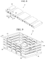
- Fig. 9 is a perspective view of a state in which the storage box is adjusted in height according to an embodiment of the present invention
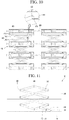
- Fig. 10 is a longitudinal cross-sectional view taken along line 10-10 of Fig. 9
- Fig. 11 is a longitudinal cross-sectional view taken along line 11-11 of Fig. 9 .
- the first sidewall 40 of the storage box 10 has a plurality of blocks 410 stacked in the vertical direction, and two blocks 410 adjacent to each other in the vertical direction are connected to each other by a link member 430.
- a slide groove 414 to which an end of the link member 430 is connected is formed inside the block 410 constituting the first sidewall 40.
- the slide groove 414 may have a length from a left end to a right end of the block 410.
- slide groove 414 may be formed on each of front and rear surfaces of the block 410.
- a bottom surface of the uppermost block 410, a top surface of the lowermost block 410, and top and bottom surfaces of the block 410 placed between the uppermost and lowermost blocks are opened and designed not to interrupt the slide of the link member 430.
- slide groove 415 may be formed at an upper side of the lowermost block 410 placed on the top surface of the base 30, and the guide grooves 411 and 412 may be formed at a lower side.
- the guide grooves 411 and 412 may be formed at the upper side, and the slide groove 415 may be formed at the lower side inside the block 410 placed at the uppermost side.
- slide grooves 415 are formed at the upper and lower sides, respectively, and the guide grooves 411 and 412 may be formed between the slide grooves 415 inside the blocks 410 stacked between the uppermost block 410 and the lowermost block 410.
- a plurality of restriction protrusions 416 may protrude from a bottom portion of the slide groove 415 to adjust a sliding position of the link member 430.
- the link member 430 may include a first link 431 and a second link 432 that intersect in an X shape, and points at which the first link 431 and the second link 432 intersect may be connected to each other a hinge shaft.
- a slide protrusion 433 may protrude from each of both ends of the first and second links 431 and 432.
- the slide protrusion 433 may protrude by a predetermined length from left and right sides of the links 431 and 432 and be inserted into the slide groove 415.
- the slide protrusion 433 passes over the restriction protrusion 416 providing from the bottom of the slide groove 415.
- the second sidewall 50 is also formed in a form in which a plurality of blocks 510 are stacked, like the first sidewall 40, and the plurality of stacked blocks 510 are connected to each other by a scissor link 520.
- the block 510 may be defined as a second block.
- Whether to apply the means for adjusting the length of the second sidewall 50 in the front and rear directions may be determined according to the size of the storage compartment 110a of the entrance refrigerator.
- the scissor link 520 is provided by connecting a plurality of link sets that intersect in an X-shape.
- hinge shafts 540 and 550 are inserted through a point at which two links constituting a link set intersect and both ends at which the plurality of link sets are connected to each other.
- the hinge shaft 540 inserted at the point at which the two links intersect is connected to the block 510, and thus, the intersection point of the link set and the block 510 is elevated as one body.
- One end of the support 530 may be rotatably connected to the lowermost link among the plurality of links constituting the scissor link 520.
- a hook protrusion 511 may protrude from the bottom of the lowermost block 510 so that the other end of the support 530 is selectively hooked.
- a manipulation protrusion 531 may protrude from a front surface of a support 530, and a guide hole 512 through which the manipulation protrusion 531 passes may be formed in a front surface of the lowermost block 510.
- the guide hole 512 is a long hole extending in a direction inclined at a predetermined angle from a horizontal plane, and the manipulation protrusion 531 may protrude from the front surface of the lowermost block 510.
- the user lowers the manipulation protrusion 531 downward in a state in which the height of the second sidewall 50 is extended, that is, in a state in which the length of the scissor link 520 increases, to allow the other end of the support 530 to be hooked with the hook protrusion 511, thereby preventing the plurality of blocks 510 from dropping downward by a load thereof.
- each of the plurality of blocks 510 descends by its own weight to return to its original state.
- Fig. 12 is an exploded perspective view illustrating a state in which the base of the storage box is separable according to an embodiment of the present invention.
- the base 30 forming the bottom portion of the storage box 10 is detachable from the first and second sidewalls 40 and 50.
- the order article is taken out from the entrance refrigerator 100 in a state in which the ordered article is stored in the storage box 10 to move to the kitchen refrigerator, and then the article together with the storage box 10 are accommodated in the kitchen refrigerator.
- the magnets 330 are embedded and installed in four corners of a top surface of the base 30, i.e., at fourth corners of a portion that is in contact with the lowermost first sidewall 40 or the lowermost second sidewall 50.
- the magnet 460 or 560 in which the attractive force acts with the magnet 330 is mounted also inside the first side wall 40 or the second side wall 50 corresponding to the directly above the magnet 330.
- Fig. 13 is a perspective view illustrating a state in which a plurality of storage boxes are stacked
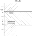
- Fig. 14 is a cross-sectional view taken along line 14-14 of Fig. 13 .
- a plurality of storage boxes 10 are capable of being stacked, and a means for preventing the stacked state of the storage boxes 10 from being easily released is proposed.
- a stacking protrusion 55 may be formed on a top surface of the storage box 10.
- the stacking protrusion 55 may be formed on a top surface of each of the first sidewall 40 or the second sidewall 50. Alternatively, it is also possible to be formed in all four places on the top surface of the storage box 10.
- a stacking groove 301 into which the stacking protrusion 55 is fitted may be formed in an edge of the bottom surface of the base 30 of the storage box 10.
- the magnet 570 may be embedded at an upper side of the stacking protrusion 55, and the magnet 370 may be embedded in the base 30 corresponding to the upper side of the stacking groove 301.
Landscapes
- Engineering & Computer Science (AREA)
- Mechanical Engineering (AREA)
- Chemical & Material Sciences (AREA)
- Combustion & Propulsion (AREA)
- Physics & Mathematics (AREA)
- Thermal Sciences (AREA)
- General Engineering & Computer Science (AREA)
- Refrigerator Housings (AREA)
- Devices That Are Associated With Refrigeration Equipment (AREA)
- Cold Air Circulating Systems And Constructional Details In Refrigerators (AREA)
- Stackable Containers (AREA)
Abstract
Description
- The present invention relates to a storage box for refrigerator at an entrance.
- Recently, a delivery service for delivering articles to a predetermined place has been activated. Particularly, when the article is fresh food, a refrigerator or a heating cabinet is provided in the delivery vehicle to prevent the food from being spoiling or getting cold so that the food is stored and delivered.
- It is common that food is generally delivered in packaging to be maintained in a cooled or warm state. The packaging material is made of environmental pollutants such as Styrofoam, thereby creating a social atmosphere to reduce usage.
- If the user is at home at the delivery time, the delivery person and the user may face-to-face to receive food, but when the user is not at home or when the delivery time is too early or too late, it is difficult for the delivery person and the user to face-to-face to receive the food.
- Therefore, even if the delivery person and the user do not directly face each other, the food may be delivered, and there is a need to not spoil or cool the food until it is finally delivered to the user.
- In order to solve this problem, recently, the refrigerator is installed at the entrance (front door) at a predetermined place, so that the delivery person keeps the food in the refrigerator to keep the food in a fresh state, and the user may access the refrigerator at a convenient time to receive the food.
- In the prior art below, an entrance refrigerator mounted on an entrance door is disclosed.
- Prior Art:
Korean Patent Publication No. 2011-0033394 (March 31, 2011 - In the entrance refrigerator disclosed in the prior art, a separate storage box is not provided in a food storage space. That is, the storage box that is capable of being accommodated in or withdrawn from the storage space of the entrance refrigerator is not disclosed.
- In addition, most of the storage boxes of the typical refrigerators are single-type storage boxes that are not capable of being adjusted in size. However, since a product ordered by a consumer through an on-line market vary in volume and shape depending on the type thereof, it is required to be able to adjust a size of a storage box to sufficiently accommodate the product.
- A storage box for a refrigerator at an entrance according to an embodiment of the present invention for achieving the above object includes: a base; a first sidewall erected at each of a front end and a rear end of a top surface of the base; and a second sidewall erected at each of a left end and a right end of the top surface of the base, wherein the first sidewall includes: a plurality blocks stacked in a vertical direction and arranged in a horizontal direction; and a plurality of connectors configured to movably connect the first blocks, which are adjacent to each other in the horizontal direction, to each other.
- According to the storage box for the entrance refrigerator according to the embodiment of the present invention having the above configuration, the width and height of the storage box may be adjusted according to the size of the ordered product, and thus, the articles having various shapes and sizes may be flexibly accommodated.
- In addition, when the large number of articles are ordered at one time, there may be the advantage that the storage box itself is carried to move, and it may be easy to move the article from the entrance refrigerator to the kitchen refrigerator.
- Also, since the bottom portion of the storage box is detachable separately, the bottom portion of the storage box may be removed in the state in which the storage box is placed on the shelf of the kitchen refrigerator, and then the wall portion may be left, so there is no need to move the articles one by one.
-
-
Fig. 1 is a view illustrating a state in which an entrance refrigerator is installed on an entrance door according to an embodiment of the present invention. -
Fig. 2 is a side view illustrating configurations of an indoor-side and an outdoor-side based on the door in the state in which the entrance refrigerator is installed on the entrance door. -
Fig. 3 is a perspective view illustrating the inside of a storage compartment of the entrance refrigerator. -
Fig. 4 is a perspective view illustrating a storage box accommodated in the entrance refrigerator according to an embodiment of the present invention. -
Fig. 5 is a perspective view of a storage box in a state in which widths of a base and a first sidewall increase. -
Fig. 6 is a longitudinal cross-sectional view of a first sidewall, taken along line 6-6 ofFig. 4 . -
Fig. 7 is a longitudinal cross-sectional view of a first sidewall, taken along line 7-7 ofFig. 5 . -
Fig. 8 is a cutaway perspective view illustrating a state in which a width of the base constituting the storage box increases according to the present invention. -
Fig. 9 is a perspective view of a state in which the storage box is adjusted in height according to an embodiment of the present invention. -
Fig. 10 is a longitudinal cross-sectional view taken along line 10-10 ofFig. 9 . -
Fig. 11 is a longitudinal cross-sectional view taken along line 11-11 ofFig. 9 . -
Fig. 12 is an exploded perspective view illustrating a state in which the base of the storage box is separable according to an embodiment of the present invention. -
Fig. 13 is a perspective view of a state in which a plurality of storage boxes are stacked. -
Fig. 14 is a cross-sectional view taken along line 14-14 ofFig. 13 . - Hereinafter, a storage box of an entrance refrigerator according to an embodiment of the present invention will be described in with reference to the accompanying drawings.
- In this specification, an entrance refrigerator or a refrigerator for an entrance is used interchangeably, but they all have the same meaning, that is, a refrigerator mounted on a door or a wall of the entrance should be interpreted the same.
-
Fig. 1 is a view illustrating a state in which an entrance refrigerator is installed on an entrance door according to an embodiment of the present invention,Fig. 2 is a side view illustrating configurations of an indoor-side and an outdoor-side based on the door in the state in which the entrance refrigerator is installed on the entrance door, andFig. 3 is a perspective view illustrating the inside of a storage compartment of the entrance refrigerator. - Referring to
Figs. 1 to 3 , anentrance refrigerator 100 according to an embodiment of the present invention may be installed at an entrance door D of a home or office. The entrance door D is installed on a wall W. A door lock L for opening the door D may be provided. - An opening H is formed in the entrance door D, and the
entrance refrigerator 100 may be inserted into the opening H to extend to an indoor-side I and an outdoor-side O. The direction will be defined. With respect to theentrance refrigerator 100, the outdoor-side O is defined as a "front side" and the indoor-side I is defined as a "rear side". - The
entrance refrigerator 100 includes acabinet 110 that forms an outer appearance thereof. - For example, the
cabinet 110 may have a substantially rectangular parallelepiped shape and be disposed to pass through the openingH. A sealer 160 is provided between the opening H and an outer surface of thecabinet 110 so that thecabinet 110 is in close contact with the opening H. - A
storage compartment 110a capable of storing food is formed inside thecabinet 110. A camera (not shown) may be provided on a top surface, that is, a ceiling, of astorage compartment 110a. The camera 118 may photograph the food stored in thestorage compartment 110a and upload the captured image to a delivery application. - For this, the entrance refrigerator may be provided with a communication module capable of communicating with the outside. For example, the communication module may include a Wi-Fi module.
- The
storage compartment 110a may be opened at the indoor-side I and the outdoor-side O. - In detail, the
entrance refrigerator 100 may be provided at one side (outside) of thestorage compartment 110a and may further include an outdoor-side door 180 capable of opening or closing thestorage compartment 110a. The outdoor-side door 180 may be disposed at the outdoor-side O and may be, for example, a door opened by a food delivery person in order to put the food therein. The outdoor-side door 180 may be in a normally locked state to prevent an opening of any door. - The
entrance refrigerator 100 may be provided at the other side (indoor-side) of thestorage compartment 110a and further include an indoor-side door 170 capable of opening or closing thestorage compartment 110a. The indoor-side door 170 may be disposed at the indoor-side (I) and may be a door opened by a user in order to collect food. - The outdoor-
side door 180 and the indoor-side door 170 may be rotatably coupled to thecabinet 110. - A
code scanner 184 capable of reading information on delivered food may be provided on a front surface of the outdoor-side door 180. Thecode scanner 184 may include a barcode scanner or a QR code scanner. - When a food delivery person brings food information (code information) provided on food or a food container to the
code scanner 184, theentrance refrigerator 100 recognizes that the food is scheduled to be delivered and release the locked state of the outdoor-side door 180. In this state, the delivery person may open the outdoor-side door 180 to store the food. - A
display portion 150 may be provided on the outdoor-side door 180. Information that is necessary for use of theentrance refrigerator 100 is displayed on thedisplay portion 150. - For example, the
display portion 150 may display a "guide comment" for the delivery person. For example, the guide comment may include a comment such as "Please recognize barcode or QR code of food to code scanner". - An input portion for inputting a password or an authentication number may be displayed on the
display portion 150. The delivery person may release the lock state of the outdoor-side door 180 by inputting the password promised in advance with the user into the input portion. - In summary, the delivery person allows the food code to be recognized to the
code scanner 184 or inputs a password or authentication number to unlock the outdoor-side door 180, and thus, after opening the outdoor-side door 180, the food is stored in thestorage compartment 110a. - The
cabinet 110 may extend toward the indoor-side I and the outdoor-side O through the door D. A front-rear width W2 of a portion of thecabinet 110, which extends toward the indoor-side I, may be greater than a front-rear width W1 of a portion, which extends toward the outdoor-side O. - According to such a configuration, since an area protruding from the door D toward the indoor-side I is large, and an area protruding from the door D toward the outdoor-side O is small, an area of the
entrance refrigerator 100, which is exposed to a space through which arbitrary people pass, may be reduced. Thus, possibility of damage to theentrance refrigerator 100 may be reduced. - A
front support portion 119 supported on an outer surface of the door D is formed on a lower portion of thecabinet 110 extending toward the indoor-side I. For example, thefront support portion 119 may be attached to a rear surface of the door D. - A cold
air supply device 200 may be provided at the lower portion of theentrance refrigerator 100. Since a front surface portion of a portion in which the relatively heavy coldair supply device 200 is accommodated, that is, thefront support portion 119 is supported or attached to the door D, theentrance refrigerator 100 may be stably mounted on the door D. - An indoor air suction hole (not shown) may be formed in the
bottom surface 115 of thecabinet 110, and an indoorair discharge hole 256 for discharging indoor space suctioned into the indoor air suction hole to the indoor space again may be formed in each of both side surface portions of thecabinet 110. - The formation positions of the indoor air suction hole and the indoor
air discharge hole 256 are not limited to this embodiment and may be formed at appropriate positions according to design conditions. - The
storage compartment 110a may be defined by an inner wall of thecabinet 110. In detail, the inner wall of thecabinet 110 includes a storage compartmentlower wall 121 forming a seating surface on which food is placed, astorage compartment sidewall 123 extending upward from both sides of the storage compartmentlower wall 121, a storage compartmentupper wall 126 forming a top surface of thestorage compartment 110a and connecting an upper portion of thestorage compartment sidewall 123, and a storage compartmentrear wall 125 connecting a rear portion of thestorage compartment sidewall 123. - The storage compartment
lower wall 121 may be provided with arib 122 protruding upward, and therib 122 may extend forward and backward and be provided in plurality, which are arranged in left and right directions. Food is placed at an upper side of the plurality ofribs 122 to prevent the food from being slid. - A cold
air inflow hole 128 for allowing the cold air inside thestorage compartment 110a to return to the coldair supply device 200 is formed in the storage compartmentlower wall 121. For example, the coldair inflow hole 128 may be formed at a rear side of the storage compartmentlower wall 121, but is not limited thereto. - A cold
air discharge hole 129 for supplying the cold air generated by the coldair supply device 200 to a side of thestorage compartment 110a is formed in thestorage compartment sidewall 123. The cold air generated in the coldair supply device 200 may be supplied to the side surface portion of thestorage compartment 110a by the configurations of the coldair inflow hole 128 and the coldair discharge hole 129, and then be returned to the coldair supply device 200 through a rear lower portion. The formation position of the cold air discharge hole is not limited to this embodiment and may be formed at an appropriate position according to design conditions. - The cold
air supply device 200 according to an embodiment of the present invention may include a thermoelectric module. - The cold
air supply device 200 includes a thermoelectric element having a heat absorption surface and a heat generation surface, a cold sink attached to the heat absorption surface, a heat sink attached to the heat generation surface, a cooling fan disposed in front of the cold sink, and a heat dissipation fan disposed behind the heat sink. - In detail, when the cooling fan is driven, air inside the
storage compartment 110a is suctioned into the cold sink through the cold air suction hole, cooled to a low temperature, and then discharged again to the coldair discharge hole 129. - When the heat dissipation fan is driven, air is suctioned into the heat sink through the indoor air suction hole to absorb heat, and then is discharged again into the indoor space through the indoor
air discharge hole 256. - The storage box according to an embodiment of the present invention may be accommodated in the
storage compartment 110a. -
Fig. 4 is a perspective view illustrating the storage box accommodated in the entrance refrigerator according to an embodiment of the present invention. - Referring to
Fig. 4 , astorage box 10 for an entrance refrigerator according to an embodiment of the present invention includes a base 30 forming a bottom portion on which an article is placed, and a pair offirst sidewalls 40 and a pair ofsecond sidewalls 50, which extend upward from an edge of thebase 30. - The pair of
first sidewalls 40 may be understood as walls defining front and rear surfaces of thebasket 10, and the pair ofsecond sidewalls 40 may be understood as walls defining left and right surfaces of the basket. - An
order information code 101 and atemperature display portion 102 may be formed on the front surface of any one of the pair offirst sidewalls 40. - The
order information code 101 may include a QR code or RF-ID tag containing information about an article ordered by a consumer. That is, when a delivery person who delivers goods brings theorder information code 101 to acode scanner 184, a locking state of the outdoor-side door 180 is released. Alternatively, when theorder information code 101 approaches a recognition range of thecode scanner 184, thecode scanner 184 may automatically recognize to unlock the outdoor-side door 180. - The
base 30 is configured to have a variable width in the left and right directions, and at least one of thefirst sidewalls 40 and thesecond sidewalls 50 has a variable width in the left and right directions and a height in a vertical direction. - Particularly, when the width of each of the
first sidewalls 40 varies in the left and right directions, the width of the base 30 also varies in the left and right directions. - Hereinafter, the structure having the variable width and height of the
storage box 10 will be described with reference to the drawings. -
Fig. 5 is a perspective view of the storage box in a state in which the widths of the base and the first sidewall increase,Fig. 6 is a longitudinal cross-sectional view of the first sidewall, taken along line 6-6 ofFig. 4, and Fig. 7 is a longitudinal cross-sectional view of the first sidewall, taken along line 7-7 ofFig. 5 . - In detail, the cross-sectional view illustrated in
Fig. 6 is a cross-sectional view in a state before the width of thefirst side wall 40 varies, and the cross-sectional view illustrated inFIG. 7 is a cross-sectional view in a state in which the width of thefirst side wall 40 varies in a direction in which the width increases. - First, a structure in which the width of the
first sidewall 40 is variable will be described. - Referring to
Figs. 5 to 7 , in thefirst sidewall 40 according to an embodiment of the present invention, a plurality ofblocks 410 are stacked vertically, and the plurality of blocks are disposed in the left and right directions. The plurality of blocks disposed in the left and right directions are movably connected by a plurality ofconnectors 420. Theblock 410 may be defined as a first block. - A
left guide groove 411 and aright guide groove 412 are formed inside theblock 410. Apartition wall 415 is formed between theleft guide groove 411 and theright guide groove 412. - In addition, a left through-
hole 416 is formed at a left side of theblock 410, and a right through-hole 417 is formed at a right side of theblock 410. - In addition, a
left magnet 413 is embedded in an inner left edge of theblock 410, and aright magnet 414 is embedded in an inner right edge of theblock 410. - The
connector 420 includes aconnector body 421 extending by a predetermined length, aleft hook end 422 extending from a left edge of theconnector body 421, and aright hook end 423 extending from a right edge of theconnector body 421. - The
left hook end 422 and theright hook end 423 extend in a direction perpendicular to theconnector body 421. - The
magnets left hook end 422 and theright hook end 423, respectively. - The
connector 420 is a means for connecting the twoblocks 410 to each other. Theleft hook end 422 is inserted into theright guide groove 412 of theblock 410 disposed at the left side, and theright hook end 423 is inserted into theleft guide groove 411 disposed at the right side. In addition, theconnector body 421 passes through the right through-hole 417 of theblock 410 disposed at the left side and the left through-hole 416 of theblock 410 disposed at the right side. - According to this configuration, as illustrated in
Fig. 1 , when the width of thestorage box 10 is in the basic state, theright magnet 414 embedded in the right side of theleft block 410 and theleft magnet 413 embedded in the left side of theright block 410 are attached to each other by attractive force therebetween, and thus, side surfaces of theadjacent blocks 410 are maintained to be in a close contact with each other. - In this state, the hook ends 422 and 423 of the
connector 420 may be spaced apart from the side surfaces of theleft guide groove 411 and theright guide groove 412 and be disposed at an approximately intermediate point. - In order to increase in width of the
storage box 10, when the left and right portions of thestorage box 10 are pulled in a width direction, a state as illustrated inFIG. 5 is obtained. - In the state of
Fig. 5 , as illustrated inFig. 7 , twoadjacent blocks 410 are separated from each other. - In detail, when the
left hook end 422 is in close contact with a right edge of theright guide groove 412 of theleft block 410, and theright hook end 423 is in close contact with the left edge of theleft guide groove 411 of theright block 410, the width of thestorage box 10 may maximally increase. - In addition, the number of
blocks 410 separated from each other in a lateral direction may be adjusted to adjust an increase in width of thestorage box 10. -
Fig. 8 is a cutaway perspective view illustrating a state in which the width of the base constituting the storage box increases according to the present invention. - Referring to
Fig. 8 , thebase 30 constituting thestorage box 10 according to the embodiment of the present invention is also provided as a combination of a plurality of base blocks 310, like thefirst sidewalls 40. - In detail, the
base 30 includes a plurality of base blocks 310 arranged in the width direction, and a plurality ofconnectors 320 connecting the adjacent base blocks 310 to each other. - In the
base block 310, like theblocks 410 constituting thefirst sidewall 40, aleft guide groove 311 and aright guide groove 312 are formed therein, and theconnector 320 includes aconnector body 321 and left and right hook ends 322 and 323 respectively extending from both ends of theconnector body 321. - The
left hook end 322 is accommodated in theright guide groove 312 of theleft base block 310, and theright hook end 323 is accommodated in theleft guide groove 312 of theright base block 310. - In addition, a
left magnet 313 and aright magnet 314 are respectively embedded in inner left and right edges of thebase block 310, respectively. - Also,
magnets left hook end 322 and theright hook end 323, respectively. - Since the variation in width of the
base 310 is the same as the method of varying in width of thefirst sidewall 40, a description thereof will be omitted. -
Fig. 9 is a perspective view of a state in which the storage box is adjusted in height according to an embodiment of the present invention,Fig. 10 is a longitudinal cross-sectional view taken along line 10-10 ofFig. 9 , andFig. 11 is a longitudinal cross-sectional view taken along line 11-11 ofFig. 9 . - Referring to
Figs. 9 and10 , thefirst sidewall 40 of thestorage box 10 according to the present invention has a plurality ofblocks 410 stacked in the vertical direction, and twoblocks 410 adjacent to each other in the vertical direction are connected to each other by alink member 430. - In detail, a
slide groove 414 to which an end of thelink member 430 is connected is formed inside theblock 410 constituting thefirst sidewall 40. Theslide groove 414 may have a length from a left end to a right end of theblock 410. - In addition, the
slide groove 414 may be formed on each of front and rear surfaces of theblock 410. - A bottom surface of the
uppermost block 410, a top surface of thelowermost block 410, and top and bottom surfaces of theblock 410 placed between the uppermost and lowermost blocks are opened and designed not to interrupt the slide of thelink member 430. - In addition, the
slide groove 415 may be formed at an upper side of thelowermost block 410 placed on the top surface of thebase 30, and theguide grooves - The
guide grooves slide groove 415 may be formed at the lower side inside theblock 410 placed at the uppermost side. - In addition, the
slide grooves 415 are formed at the upper and lower sides, respectively, and theguide grooves slide grooves 415 inside theblocks 410 stacked between theuppermost block 410 and thelowermost block 410. - In addition, a plurality of
restriction protrusions 416 may protrude from a bottom portion of theslide groove 415 to adjust a sliding position of thelink member 430. - The
link member 430 may include a first link 431 and asecond link 432 that intersect in an X shape, and points at which the first link 431 and thesecond link 432 intersect may be connected to each other a hinge shaft. - A
slide protrusion 433 may protrude from each of both ends of the first andsecond links 431 and 432. Theslide protrusion 433 may protrude by a predetermined length from left and right sides of thelinks 431 and 432 and be inserted into theslide groove 415. - In addition, when a height of the
storage box 10 is adjusted by an operation in which the verticallyadjacent blocks 410 move away from each other or close to each other in the vertical direction, theslide protrusion 433 passes over therestriction protrusion 416 providing from the bottom of theslide groove 415. - In addition, when the vertical movement of the
block 410 is stopped, theslide protrusion 433 is caught by therestriction protrusion 416 to prevent theupper block 410 from falling to thelower block 410. - Referring to
Figs. 9 and11 , thesecond sidewall 50 is also formed in a form in which a plurality ofblocks 510 are stacked, like thefirst sidewall 40, and the plurality of stackedblocks 510 are connected to each other by ascissor link 520. Theblock 510 may be defined as a second block. - Although it is illustrated that only the height of the
second sidewall 50 is adjusted in this embodiment, it is not excluded that the configuration is the same as that of thefirst sidewall 40. - Whether to apply the means for adjusting the length of the
second sidewall 50 in the front and rear directions may be determined according to the size of thestorage compartment 110a of the entrance refrigerator. - On the other hand, the
scissor link 520, as illustrated in the drawings, is provided by connecting a plurality of link sets that intersect in an X-shape. In detail, hingeshafts - According to this structure, when a width of the
scissor link 520 becomes narrow, the length of thescissor link 520 increases, and when the width increases, the length of the scissor link decreases. - In addition, the
hinge shaft 540 inserted at the point at which the two links intersect is connected to theblock 510, and thus, the intersection point of the link set and theblock 510 is elevated as one body. - Thus, when the height of the
second sidewall 50 increases while theblocks 510 adjacent to each other are spaced apart from each other, a distance between the verticallyadjacent blocks 540 increases. - One end of the
support 530 may be rotatably connected to the lowermost link among the plurality of links constituting thescissor link 520. In addition, ahook protrusion 511 may protrude from the bottom of thelowermost block 510 so that the other end of thesupport 530 is selectively hooked. - A
manipulation protrusion 531 may protrude from a front surface of asupport 530, and aguide hole 512 through which themanipulation protrusion 531 passes may be formed in a front surface of thelowermost block 510. - The
guide hole 512 is a long hole extending in a direction inclined at a predetermined angle from a horizontal plane, and themanipulation protrusion 531 may protrude from the front surface of thelowermost block 510. - Thus, the user lowers the
manipulation protrusion 531 downward in a state in which the height of thesecond sidewall 50 is extended, that is, in a state in which the length of thescissor link 520 increases, to allow the other end of thesupport 530 to be hooked with thehook protrusion 511, thereby preventing the plurality ofblocks 510 from dropping downward by a load thereof. - In addition, in order to lower the
second sidewall 50 to its original state, when the user pushes up themanipulation protrusion 531 so that the other end of thesupport 530 is released from thehook protrusion 511, each of the plurality ofblocks 510 descends by its own weight to return to its original state. -
Fig. 12 is an exploded perspective view illustrating a state in which the base of the storage box is separable according to an embodiment of the present invention. - Referring to
Fig. 12 , thebase 30 forming the bottom portion of thestorage box 10 is detachable from the first andsecond sidewalls - In detail, the order article is taken out from the
entrance refrigerator 100 in a state in which the ordered article is stored in thestorage box 10 to move to the kitchen refrigerator, and then the article together with thestorage box 10 are accommodated in the kitchen refrigerator. - In this state, only the
base 30 is slid forward to open a bottom portion of thestorage box 10. Then, the stored article is directly seated on a shelf of the refrigerator. - Thereafter, when the
first sidewall 40 and thesecond sidewall 50 are lifted upward to a height that does not interfere with the article and then taken out of the refrigerator, it is unnecessary to take out the articles stored in thestorage box 10 one by one. - For this, the
magnets 330 are embedded and installed in four corners of a top surface of thebase 30, i.e., at fourth corners of a portion that is in contact with the lowermostfirst sidewall 40 or the lowermostsecond sidewall 50. - In addition, the
magnet magnet 330 is mounted also inside thefirst side wall 40 or thesecond side wall 50 corresponding to the directly above themagnet 330. -
Fig. 13 is a perspective view illustrating a state in which a plurality of storage boxes are stacked, andFig. 14 is a cross-sectional view taken along line 14-14 ofFig. 13 . - Referring to
Figs. 13 and14 , a plurality ofstorage boxes 10 are capable of being stacked, and a means for preventing the stacked state of thestorage boxes 10 from being easily released is proposed. - In detail, a stacking protrusion 55 may be formed on a top surface of the
storage box 10. - The stacking protrusion 55 may be formed on a top surface of each of the
first sidewall 40 or thesecond sidewall 50. Alternatively, it is also possible to be formed in all four places on the top surface of thestorage box 10. - In addition, a stacking
groove 301 into which the stacking protrusion 55 is fitted may be formed in an edge of the bottom surface of thebase 30 of thestorage box 10. - Furthermore, the magnet 570 may be embedded at an upper side of the stacking protrusion 55, and the
magnet 370 may be embedded in the base 30 corresponding to the upper side of the stackinggroove 301. - Then, it is possible to prevent the upper storage box from falling or drop from the storage box to the lower side by firstly coupling the protrusion to the groove, and secondly by the attractive force between the
magnets 370 and 570.
Claims (17)
- A storage box for a refrigerator at an entrance, the storage box comprising:a base;a first sidewall erected at each of a front end and a rear end of a top surface of the base; anda second sidewall erected at each of a left end and a right end of the top surface of the base,wherein the first sidewall comprises:a plurality blocks stacked in a vertical direction and arranged in a horizontal direction; anda plurality of connectors configured to movably connect the first blocks, which are adjacent to each other in the horizontal direction, to each other.
- The storage box according to claim 1, wherein a left guide groove and a right guide groove are defined at left and right inner sides of the first block, respectively,wherein the left guide groove and the right guide groove are partitioned by a partition wall, anda left through-hole and a right through-hole are defined in left and right surfaces of the first block, respectively.
- The storage box according to claim 2, wherein each of the plurality of connectors comprises:a connector body extending by a predetermined length, the connector body having both ends, which are inserted into the right through-hole of the left block and the left through-hole of the right block, respectively; anda left hook end and a right hook end, which respectively extend from both ends of the connector body in a direction crossing the connection body,wherein the left hook end is accommodated in the right guide groove of the left block, andthe right hook end is accommodated in the left guide groove of the right block.
- The storage box according to claim 3, wherein a magnet is provided at each of a left inner edge and a right inner edge of the block.
- The storage box according to claim 3, wherein a magnet is provided inside each of the left hook end and the right hook end.
- The storage box according to claim 1, further comprising a link member configured to movably connect the first blocks, which are adjacent to each other in the vertical direction, to each other.
- The storage box according to claim 6, wherein the link member comprises a first link and a second link, which cross each other in an X shape,
wherein a slide groove, into which ends of the link are accommodated, extends in a longitudinal direction of the first block at one side or both sides of upper and lower sides inside the first block. - The storage box according to claim 7, wherein a slide protrusion extending in a direction crossing the first link and the second link protrudes from each of both ends of the first link and the second link, and
the slide groove is defined in each of front and rear inner surfaces of the first block. - The storage box according to claim 8, wherein a plurality of restriction protrusions are disposed on a bottom of the slide groove.
- The storage box according to claim 1, wherein the second sidewall comprises:a plurality of second blocks stacked in at least vertical direction; anda scissor link configured to movably connect the plurality of second blocks to each other.
- The storage box according to claim 10, wherein the scissor link comprises a plurality of link sets connected to be relatively rotatable with respect to each other,wherein each of the plurality of link sets comprises a pair of links crossing each other in an X shape,both ends of the plurality of link sets are connected to be relatively rotatable with respect to each other by a first hinge shaft, andthe pair of links are connected to be relatively rotatable with respect to each other by a second hinge shaft at an intersection,wherein the second hinge shaft is coupled to the second block.
- The storage box according to claim 11, further comprising:a support having one end rotatably connected to one side of the lowermost link;a hook protrusion protruding from a bottom of an inside of the lowermost second block so that the other end of the support is selectively hooked; anda manipulation protrusion protruding from a front surface of the support,wherein a guide hole having a long hole shape, through which the manipulation protrusion passes, is defined in the lowermost second block.
- The storage box according to claim 1, wherein the base is detachably coupled to a bottom surface of each of the first and second sidewalls in a sliding manner.
- The storage box according to claim 13, wherein a magnet is provided at each of an inside of the first or second sidewall and an inside of the base, which correspond to an area that the first or second sidewall is in contact with the base.
- The storage box according to claim 1, further comprising a stacking protrusion protruding from one side or each of both sides of a top surface of the uppermost first sidewall or a top surface of the uppermost second sidewall,
wherein a stacking groove configured to accommodate the stacking protrusion is defined in a bottom surface of the base. - The storage box according to claim 15, wherein a magnet is provided at each of:an inside of the stacking protrusion; andan inside of the base, which corresponds to an upper side of the stacking groove.
- The storage box according to claim 1, further comprising: at least one of:an order information code provided at one side of the first sidewall or the second sidewall; ora temperature display portion provided at the other side of the first sidewall or the second sidewall.
Applications Claiming Priority (3)
| Application Number | Priority Date | Filing Date | Title |
|---|---|---|---|
| KR1020190021867A KR102766351B1 (en) | 2019-02-25 | 2019-02-25 | Refrigerator installed at an entrance of the place |
| KR1020190065626A KR102744937B1 (en) | 2019-06-03 | 2019-06-03 | Storage box for refrigerator installed at an entrance of the place |
| PCT/KR2020/002081 WO2020175835A1 (en) | 2019-02-25 | 2020-02-13 | Storage box for refrigerator at entrance |
Publications (3)
| Publication Number | Publication Date |
|---|---|
| EP3933322A1 true EP3933322A1 (en) | 2022-01-05 |
| EP3933322A4 EP3933322A4 (en) | 2022-11-30 |
| EP3933322B1 EP3933322B1 (en) | 2025-04-02 |
Family
ID=72238528
Family Applications (1)
| Application Number | Title | Priority Date | Filing Date |
|---|---|---|---|
| EP20763784.4A Active EP3933322B1 (en) | 2019-02-25 | 2020-02-13 | Storage box for refrigerator at entrance |
Country Status (5)
| Country | Link |
|---|---|
| US (1) | US11841185B2 (en) |
| EP (1) | EP3933322B1 (en) |
| CN (1) | CN113474604A (en) |
| AU (1) | AU2020227569B2 (en) |
| WO (1) | WO2020175835A1 (en) |
Family Cites Families (20)
| Publication number | Priority date | Publication date | Assignee | Title |
|---|---|---|---|---|
| US3577673A (en) * | 1968-01-31 | 1971-05-04 | Ottorino Monestier | Block elements of variable angular form |
| GB2293594A (en) | 1994-09-08 | 1996-04-03 | Ngai Keung Metal & Plastic Man | Panels for building containers |
| US5774053A (en) | 1996-05-02 | 1998-06-30 | Porter; David | Storage device for the delivery and pickup of goods |
| JPH10236426A (en) | 1997-02-27 | 1998-09-08 | Nobuo Sugawara | Packaging container case |
| US20020121520A1 (en) * | 2000-04-05 | 2002-09-05 | Govrik Devee J. | Expandable organizer |
| US20080251513A1 (en) * | 2007-04-11 | 2008-10-16 | Arne Vatn | Telescopic container |
| KR20110033394A (en) | 2009-09-25 | 2011-03-31 | 조영택 | Refrigerator attached to front door and front door |
| CN202609381U (en) * | 2011-03-28 | 2012-12-19 | 四川宏华石油设备有限公司 | Fluid container, fluid container device and fluid container assembly |
| WO2013120260A1 (en) * | 2012-02-15 | 2013-08-22 | 四川宏华石油设备有限公司 | Shale gas production method |
| DE102012105186B4 (en) * | 2012-06-14 | 2015-01-08 | Michael Lutter | Collapsible container |
| US8864248B2 (en) | 2013-02-08 | 2014-10-21 | Giga-Byte Technology Co., Ltd. | Computer case |
| KR101632535B1 (en) | 2015-04-20 | 2016-06-21 | 변승하 | magnetic block toy |
| US9781900B2 (en) | 2015-06-04 | 2017-10-10 | Ford Global Technologies, Llc | Pet transport |
| SG10201508941SA (en) | 2015-07-03 | 2017-02-27 | Zhi Loong Lam | Intermodal devices and methods |
| KR101753211B1 (en) | 2015-10-02 | 2017-07-04 | 전원 | Possible height adjustable shelves system |
| KR20180064761A (en) | 2016-12-06 | 2018-06-15 | (주) 프렉코 | Lifting apparatus |
| CN106742548B (en) | 2016-12-29 | 2018-07-31 | 广州市仓配速效电子商务有限责任公司 | A kind of expansion and shrinkage type box for material circulation |
| KR102030233B1 (en) | 2017-04-12 | 2019-10-08 | 이흥범 | Apparatus for processing information based on internet of thing for containers and method for managing food using the same |
| US10279956B1 (en) * | 2017-06-20 | 2019-05-07 | Jose Gamboa | Vertical and horizontal simultaneously and selectively expandable structure |
| CN108284999B (en) | 2018-02-05 | 2019-08-02 | 温州职业技术学院 | A kind of scalable band separation packing case easy to use |
-
2020
- 2020-02-13 WO PCT/KR2020/002081 patent/WO2020175835A1/en not_active Ceased
- 2020-02-13 CN CN202080016315.9A patent/CN113474604A/en active Pending
- 2020-02-13 EP EP20763784.4A patent/EP3933322B1/en active Active
- 2020-02-13 US US17/433,570 patent/US11841185B2/en active Active
- 2020-02-13 AU AU2020227569A patent/AU2020227569B2/en active Active
Also Published As
| Publication number | Publication date |
|---|---|
| AU2020227569B2 (en) | 2023-08-17 |
| EP3933322B1 (en) | 2025-04-02 |
| US20220120491A1 (en) | 2022-04-21 |
| WO2020175835A1 (en) | 2020-09-03 |
| EP3933322A4 (en) | 2022-11-30 |
| CN113474604A (en) | 2021-10-01 |
| AU2020227569A1 (en) | 2021-10-14 |
| US11841185B2 (en) | 2023-12-12 |
Similar Documents
| Publication | Publication Date | Title |
|---|---|---|
| US11859898B2 (en) | Refrigerator having scissors lift for drawer | |
| US20190047460A1 (en) | Multi-modal distribution systems and methods using vending kiosks and autonomous delivery vehicles | |
| CN113597633A (en) | Modular vending machine | |
| JP3953436B2 (en) | Refrigerator partitioning device | |
| US11841185B2 (en) | Storage box for refrigerator at entrance | |
| KR102744937B1 (en) | Storage box for refrigerator installed at an entrance of the place | |
| KR20200144916A (en) | Commodity deposit device | |
| EP3699525B1 (en) | Entrance refrigerator | |
| EP3933321B1 (en) | Refrigerator for front door | |
| CN116583467A (en) | Automated warehouse with refrigerator | |
| JP5316223B2 (en) | vending machine | |
| KR20210030139A (en) | Refrigerator installed at an entrance of the place | |
| US12405048B2 (en) | Locker with valve assembly | |
| US12203692B2 (en) | Refrigerator comprising module having multiple storage chambers | |
| KR20210026663A (en) | Refrigerator installed at an entrance of the place | |
| CN218672784U (en) | Refrigerator with detachable storage frame | |
| KR102153897B1 (en) | Refrigerator | |
| JPH0742359Y2 (en) | Open showcase | |
| CN115574513A (en) | Freezer with reversible storage frame | |
| EP4067784A1 (en) | Refrigerator including module having plurality of storage chambers | |
| CN115628580A (en) | Refrigerator with detachable storage frame | |
| JP3927361B2 (en) | Storage | |
| KR20210026662A (en) | Refrigerator installed at an entrance of the place | |
| JPH11120431A (en) | vending machine | |
| JP5381540B2 (en) | vending machine |
Legal Events
| Date | Code | Title | Description |
|---|---|---|---|
| STAA | Information on the status of an ep patent application or granted ep patent |
Free format text: STATUS: THE INTERNATIONAL PUBLICATION HAS BEEN MADE |
|
| PUAI | Public reference made under article 153(3) epc to a published international application that has entered the european phase |
Free format text: ORIGINAL CODE: 0009012 |
|
| STAA | Information on the status of an ep patent application or granted ep patent |
Free format text: STATUS: REQUEST FOR EXAMINATION WAS MADE |
|
| 17P | Request for examination filed |
Effective date: 20210921 |
|
| AK | Designated contracting states |
Kind code of ref document: A1 Designated state(s): AL AT BE BG CH CY CZ DE DK EE ES FI FR GB GR HR HU IE IS IT LI LT LU LV MC MK MT NL NO PL PT RO RS SE SI SK SM TR |
|
| DAV | Request for validation of the european patent (deleted) | ||
| DAX | Request for extension of the european patent (deleted) | ||
| A4 | Supplementary search report drawn up and despatched |
Effective date: 20221103 |
|
| RIC1 | Information provided on ipc code assigned before grant |
Ipc: F25D 25/00 20060101ALI20221027BHEP Ipc: B65D 21/02 20060101ALI20221027BHEP Ipc: B65D 21/08 20060101ALI20221027BHEP Ipc: F25B 21/02 20060101ALI20221027BHEP Ipc: F25D 21/14 20060101ALI20221027BHEP Ipc: F25D 23/10 20060101AFI20221027BHEP |
|
| REG | Reference to a national code |
Ref country code: DE Ref legal event code: R079 Free format text: PREVIOUS MAIN CLASS: F25D0025000000 Ipc: F25D0023100000 Ref country code: DE Ref legal event code: R079 Ref document number: 602020048765 Country of ref document: DE Free format text: PREVIOUS MAIN CLASS: F25D0025000000 Ipc: F25D0023100000 |
|
| GRAP | Despatch of communication of intention to grant a patent |
Free format text: ORIGINAL CODE: EPIDOSNIGR1 |
|
| STAA | Information on the status of an ep patent application or granted ep patent |
Free format text: STATUS: GRANT OF PATENT IS INTENDED |
|
| RIC1 | Information provided on ipc code assigned before grant |
Ipc: F25D 25/00 20060101ALI20241108BHEP Ipc: B65D 21/02 20060101ALI20241108BHEP Ipc: B65D 21/08 20060101ALI20241108BHEP Ipc: F25B 21/02 20060101ALI20241108BHEP Ipc: F25D 21/14 20060101ALI20241108BHEP Ipc: F25D 23/10 20060101AFI20241108BHEP |
|
| INTG | Intention to grant announced |
Effective date: 20241121 |
|
| GRAS | Grant fee paid |
Free format text: ORIGINAL CODE: EPIDOSNIGR3 |
|
| GRAA | (expected) grant |
Free format text: ORIGINAL CODE: 0009210 |
|
| STAA | Information on the status of an ep patent application or granted ep patent |
Free format text: STATUS: THE PATENT HAS BEEN GRANTED |
|
| AK | Designated contracting states |
Kind code of ref document: B1 Designated state(s): AL AT BE BG CH CY CZ DE DK EE ES FI FR GB GR HR HU IE IS IT LI LT LU LV MC MK MT NL NO PL PT RO RS SE SI SK SM TR |
|
| REG | Reference to a national code |
Ref country code: GB Ref legal event code: FG4D |
|
| REG | Reference to a national code |
Ref country code: CH Ref legal event code: EP |
|
| REG | Reference to a national code |
Ref country code: DE Ref legal event code: R096 Ref document number: 602020048765 Country of ref document: DE |
|
| REG | Reference to a national code |
Ref country code: IE Ref legal event code: FG4D |
|
| REG | Reference to a national code |
Ref country code: NL Ref legal event code: MP Effective date: 20250402 |
|
| PG25 | Lapsed in a contracting state [announced via postgrant information from national office to epo] |
Ref country code: NL Free format text: LAPSE BECAUSE OF FAILURE TO SUBMIT A TRANSLATION OF THE DESCRIPTION OR TO PAY THE FEE WITHIN THE PRESCRIBED TIME-LIMIT Effective date: 20250402 |
|
| REG | Reference to a national code |
Ref country code: AT Ref legal event code: MK05 Ref document number: 1781624 Country of ref document: AT Kind code of ref document: T Effective date: 20250402 |
|
| PG25 | Lapsed in a contracting state [announced via postgrant information from national office to epo] |
Ref country code: FI Free format text: LAPSE BECAUSE OF FAILURE TO SUBMIT A TRANSLATION OF THE DESCRIPTION OR TO PAY THE FEE WITHIN THE PRESCRIBED TIME-LIMIT Effective date: 20250402 Ref country code: ES Free format text: LAPSE BECAUSE OF FAILURE TO SUBMIT A TRANSLATION OF THE DESCRIPTION OR TO PAY THE FEE WITHIN THE PRESCRIBED TIME-LIMIT Effective date: 20250402 Ref country code: PT Free format text: LAPSE BECAUSE OF FAILURE TO SUBMIT A TRANSLATION OF THE DESCRIPTION OR TO PAY THE FEE WITHIN THE PRESCRIBED TIME-LIMIT Effective date: 20250804 |
|
| REG | Reference to a national code |
Ref country code: LT Ref legal event code: MG9D |
|
| PG25 | Lapsed in a contracting state [announced via postgrant information from national office to epo] |
Ref country code: NO Free format text: LAPSE BECAUSE OF FAILURE TO SUBMIT A TRANSLATION OF THE DESCRIPTION OR TO PAY THE FEE WITHIN THE PRESCRIBED TIME-LIMIT Effective date: 20250702 Ref country code: GR Free format text: LAPSE BECAUSE OF FAILURE TO SUBMIT A TRANSLATION OF THE DESCRIPTION OR TO PAY THE FEE WITHIN THE PRESCRIBED TIME-LIMIT Effective date: 20250703 |
|
| PG25 | Lapsed in a contracting state [announced via postgrant information from national office to epo] |
Ref country code: PL Free format text: LAPSE BECAUSE OF FAILURE TO SUBMIT A TRANSLATION OF THE DESCRIPTION OR TO PAY THE FEE WITHIN THE PRESCRIBED TIME-LIMIT Effective date: 20250402 |
|
| PG25 | Lapsed in a contracting state [announced via postgrant information from national office to epo] |
Ref country code: BG Free format text: LAPSE BECAUSE OF FAILURE TO SUBMIT A TRANSLATION OF THE DESCRIPTION OR TO PAY THE FEE WITHIN THE PRESCRIBED TIME-LIMIT Effective date: 20250402 |
|
| PG25 | Lapsed in a contracting state [announced via postgrant information from national office to epo] |
Ref country code: HR Free format text: LAPSE BECAUSE OF FAILURE TO SUBMIT A TRANSLATION OF THE DESCRIPTION OR TO PAY THE FEE WITHIN THE PRESCRIBED TIME-LIMIT Effective date: 20250402 |
|
| PG25 | Lapsed in a contracting state [announced via postgrant information from national office to epo] |
Ref country code: AT Free format text: LAPSE BECAUSE OF FAILURE TO SUBMIT A TRANSLATION OF THE DESCRIPTION OR TO PAY THE FEE WITHIN THE PRESCRIBED TIME-LIMIT Effective date: 20250402 |
|
| PG25 | Lapsed in a contracting state [announced via postgrant information from national office to epo] |
Ref country code: RS Free format text: LAPSE BECAUSE OF FAILURE TO SUBMIT A TRANSLATION OF THE DESCRIPTION OR TO PAY THE FEE WITHIN THE PRESCRIBED TIME-LIMIT Effective date: 20250702 |
|
| PG25 | Lapsed in a contracting state [announced via postgrant information from national office to epo] |
Ref country code: IS Free format text: LAPSE BECAUSE OF FAILURE TO SUBMIT A TRANSLATION OF THE DESCRIPTION OR TO PAY THE FEE WITHIN THE PRESCRIBED TIME-LIMIT Effective date: 20250802 |
|
| PG25 | Lapsed in a contracting state [announced via postgrant information from national office to epo] |
Ref country code: LV Free format text: LAPSE BECAUSE OF FAILURE TO SUBMIT A TRANSLATION OF THE DESCRIPTION OR TO PAY THE FEE WITHIN THE PRESCRIBED TIME-LIMIT Effective date: 20250402 |
|
| REG | Reference to a national code |
Ref country code: DE Ref legal event code: R097 Ref document number: 602020048765 Country of ref document: DE |
|
| PG25 | Lapsed in a contracting state [announced via postgrant information from national office to epo] |
Ref country code: SM Free format text: LAPSE BECAUSE OF FAILURE TO SUBMIT A TRANSLATION OF THE DESCRIPTION OR TO PAY THE FEE WITHIN THE PRESCRIBED TIME-LIMIT Effective date: 20250402 Ref country code: DK Free format text: LAPSE BECAUSE OF FAILURE TO SUBMIT A TRANSLATION OF THE DESCRIPTION OR TO PAY THE FEE WITHIN THE PRESCRIBED TIME-LIMIT Effective date: 20250402 |
|
| PG25 | Lapsed in a contracting state [announced via postgrant information from national office to epo] |
Ref country code: CZ Free format text: LAPSE BECAUSE OF FAILURE TO SUBMIT A TRANSLATION OF THE DESCRIPTION OR TO PAY THE FEE WITHIN THE PRESCRIBED TIME-LIMIT Effective date: 20250402 |
|
| PG25 | Lapsed in a contracting state [announced via postgrant information from national office to epo] |
Ref country code: EE Free format text: LAPSE BECAUSE OF FAILURE TO SUBMIT A TRANSLATION OF THE DESCRIPTION OR TO PAY THE FEE WITHIN THE PRESCRIBED TIME-LIMIT Effective date: 20250402 |
|
| PG25 | Lapsed in a contracting state [announced via postgrant information from national office to epo] |
Ref country code: RO Free format text: LAPSE BECAUSE OF FAILURE TO SUBMIT A TRANSLATION OF THE DESCRIPTION OR TO PAY THE FEE WITHIN THE PRESCRIBED TIME-LIMIT Effective date: 20250402 Ref country code: SK Free format text: LAPSE BECAUSE OF FAILURE TO SUBMIT A TRANSLATION OF THE DESCRIPTION OR TO PAY THE FEE WITHIN THE PRESCRIBED TIME-LIMIT Effective date: 20250402 |
|
| PG25 | Lapsed in a contracting state [announced via postgrant information from national office to epo] |
Ref country code: IT Free format text: LAPSE BECAUSE OF FAILURE TO SUBMIT A TRANSLATION OF THE DESCRIPTION OR TO PAY THE FEE WITHIN THE PRESCRIBED TIME-LIMIT Effective date: 20250402 |
|
| PLBE | No opposition filed within time limit |
Free format text: ORIGINAL CODE: 0009261 |
|
| STAA | Information on the status of an ep patent application or granted ep patent |
Free format text: STATUS: NO OPPOSITION FILED WITHIN TIME LIMIT |
|
| REG | Reference to a national code |
Ref country code: CH Ref legal event code: L10 Free format text: ST27 STATUS EVENT CODE: U-0-0-L10-L00 (AS PROVIDED BY THE NATIONAL OFFICE) Effective date: 20260211 |
|
| 26N | No opposition filed |
Effective date: 20260105 |
|
| PGFP | Annual fee paid to national office [announced via postgrant information from national office to epo] |
Ref country code: DE Payment date: 20260105 Year of fee payment: 7 |