EP3933315A1 - Insulated glass corner assembly - Google Patents
Insulated glass corner assembly Download PDFInfo
- Publication number
- EP3933315A1 EP3933315A1 EP21182552.6A EP21182552A EP3933315A1 EP 3933315 A1 EP3933315 A1 EP 3933315A1 EP 21182552 A EP21182552 A EP 21182552A EP 3933315 A1 EP3933315 A1 EP 3933315A1
- Authority
- EP
- European Patent Office
- Prior art keywords
- glass panel
- end region
- interior surface
- exterior surface
- corner assembly
- Prior art date
- Legal status (The legal status is an assumption and is not a legal conclusion. Google has not performed a legal analysis and makes no representation as to the accuracy of the status listed.)
- Granted
Links
Images

Classifications
-
- F—MECHANICAL ENGINEERING; LIGHTING; HEATING; WEAPONS; BLASTING
- F25—REFRIGERATION OR COOLING; COMBINED HEATING AND REFRIGERATION SYSTEMS; HEAT PUMP SYSTEMS; MANUFACTURE OR STORAGE OF ICE; LIQUEFACTION SOLIDIFICATION OF GASES
- F25D—REFRIGERATORS; COLD ROOMS; ICE-BOXES; COOLING OR FREEZING APPARATUS NOT OTHERWISE PROVIDED FOR
- F25D23/00—General constructional features
-
- A—HUMAN NECESSITIES
- A47—FURNITURE; DOMESTIC ARTICLES OR APPLIANCES; COFFEE MILLS; SPICE MILLS; SUCTION CLEANERS IN GENERAL
- A47F—SPECIAL FURNITURE, FITTINGS, OR ACCESSORIES FOR SHOPS, STOREHOUSES, BARS, RESTAURANTS OR THE LIKE; PAYING COUNTERS
- A47F3/00—Show cases or show cabinets
- A47F3/12—Clamps or other devices for supporting, fastening, or connecting glass plates, panels or the like
-
- A—HUMAN NECESSITIES
- A47—FURNITURE; DOMESTIC ARTICLES OR APPLIANCES; COFFEE MILLS; SPICE MILLS; SUCTION CLEANERS IN GENERAL
- A47F—SPECIAL FURNITURE, FITTINGS, OR ACCESSORIES FOR SHOPS, STOREHOUSES, BARS, RESTAURANTS OR THE LIKE; PAYING COUNTERS
- A47F3/00—Show cases or show cabinets
- A47F3/005—Show cases or show cabinets with glass panels
-
- A—HUMAN NECESSITIES
- A47—FURNITURE; DOMESTIC ARTICLES OR APPLIANCES; COFFEE MILLS; SPICE MILLS; SUCTION CLEANERS IN GENERAL
- A47F—SPECIAL FURNITURE, FITTINGS, OR ACCESSORIES FOR SHOPS, STOREHOUSES, BARS, RESTAURANTS OR THE LIKE; PAYING COUNTERS
- A47F3/00—Show cases or show cabinets
- A47F3/04—Show cases or show cabinets air-conditioned, refrigerated
- A47F3/0404—Cases or cabinets of the closed type
- A47F3/0426—Details
- A47F3/0434—Glass or transparent panels
-
- F—MECHANICAL ENGINEERING; LIGHTING; HEATING; WEAPONS; BLASTING
- F16—ENGINEERING ELEMENTS AND UNITS; GENERAL MEASURES FOR PRODUCING AND MAINTAINING EFFECTIVE FUNCTIONING OF MACHINES OR INSTALLATIONS; THERMAL INSULATION IN GENERAL
- F16B—DEVICES FOR FASTENING OR SECURING CONSTRUCTIONAL ELEMENTS OR MACHINE PARTS TOGETHER, e.g. NAILS, BOLTS, CIRCLIPS, CLAMPS, CLIPS OR WEDGES; JOINTS OR JOINTING
- F16B12/00—Jointing of furniture or the like, e.g. hidden from exterior
- F16B12/02—Joints between panels and corner posts
-
- F—MECHANICAL ENGINEERING; LIGHTING; HEATING; WEAPONS; BLASTING
- F25—REFRIGERATION OR COOLING; COMBINED HEATING AND REFRIGERATION SYSTEMS; HEAT PUMP SYSTEMS; MANUFACTURE OR STORAGE OF ICE; LIQUEFACTION SOLIDIFICATION OF GASES
- F25D—REFRIGERATORS; COLD ROOMS; ICE-BOXES; COOLING OR FREEZING APPARATUS NOT OTHERWISE PROVIDED FOR
- F25D2400/00—General features of, or devices for refrigerators, cold rooms, ice-boxes, or for cooling or freezing apparatus not covered by any other subclass
- F25D2400/10—Refrigerator top-coolers
-
- F—MECHANICAL ENGINEERING; LIGHTING; HEATING; WEAPONS; BLASTING
- F25—REFRIGERATION OR COOLING; COMBINED HEATING AND REFRIGERATION SYSTEMS; HEAT PUMP SYSTEMS; MANUFACTURE OR STORAGE OF ICE; LIQUEFACTION SOLIDIFICATION OF GASES
- F25D—REFRIGERATORS; COLD ROOMS; ICE-BOXES; COOLING OR FREEZING APPARATUS NOT OTHERWISE PROVIDED FOR
- F25D2400/00—General features of, or devices for refrigerators, cold rooms, ice-boxes, or for cooling or freezing apparatus not covered by any other subclass
- F25D2400/18—Aesthetic features
Definitions
- the invention relates to refrigerated display cases. More particularly, the invention relates to the corner assemblies used between two insulated glass panels of such refrigerated display cases.
- Refrigerated display cases are used in a variety of commercial settings.
- refrigerated display cases can be used as a product presentation platform (e.g., in a grocery store) for chilled products.
- These refrigerated display cases commonly include a bottom surface and plurality of insulated glass panels extending around the perimeter of the bottom surface.
- the insulated glass panels form corner assemblies with one another.
- the corner assemblies are held together using at least one spacer.
- spacers hold the insulated glass panels a distance from one another and produce a seal between the insulated glass panels.
- these spacers traditionally are not transparent. Consequently, the use of spacers within refrigerated display cases is not ideal, as the spacers not only take away from the aesthetic appeal of the refrigerated display case, but also reduce the ability of the consumer to see the products within the refrigerated display case.
- a corner assembly including a first glass panel, a second glass panel, a sealing element, and a tape
- the first glass panel includes an end region, an interior surface, and an exterior surface.
- the second glass panel includes an end region, an interior surface, and an exterior surface.
- the sealing element is disposed between the end region of the first glass panel and the end region of the second glass panel.
- the tape includes an adhesive on an interior surface. The interior surface of the tape is adhesively attached to the exterior surface of the first glass panel and the exterior surface of the second glass panel.
- the first glass panel and the second glass panel may each respectively have a multi-layer insulated structure.
- the corner assembly may further include an external corner element with a first end, a second end, an interior surface, and an exterior surface.
- the interior surface of the external corner element may be disposed over at least a portion of the exterior surface of the tape.
- At least one of the first end and the second end of the external corner element may include an adhesive.
- the sealing element may include an internal portion and a leg, the leg extending approximately perpendicular from the internal portion.
- the leg may have a thickness less than half a thickness of the internal portion.
- the leg may have a rigidity greater than a rigidity of the internal portion.
- the internal portion may be disposed between the interior surface of the first glass panel and the interior surface of the second glass panel.
- the leg may be disposed between the end region of the first glass panel and the end region of the second glass panel.
- the end region of the first glass panel and the end region of the second glass panel may each respectively have a stepped structure.
- the stepped structure of the end region of the first glass panel may include a first portion and a second portion, the first portion having a width greater than a width of the second portion.
- the stepped structure of the end region of the second glass panel may include a first portion and a second portion, the first portion having a width less than a width of the second portion.
- At least one of the end region of the first glass panel and the end region of the second glass panel may include a heating element.
- a heating element may be disposed in the first portion of the stepped structure of the end region of the first glass panel.
- a heating element may be disposed between the first portion and the second portion of the stepped structure of the end region of the second glass panel.
- a method of manufacturing at least a portion of a refrigerated display case includes a first glass panel and a second glass panel, each respectively including an end region, an interior surface, and an exterior surface.
- the method includes a step for positioning an end region of the first glass panel approximately adjacent to the end region of the second glass panel.
- the method includes a step for inserting a sealing element between the end region of the first glass panel and the end region of the second glass panel.
- the method includes a step for adhesively attaching an interior surface of a tape to the exterior surface of the first glass panel and the exterior surface of the second glass panel.
- the method may further include a step for adhesively attaching an interior surface of an external corner element to at least a portion of an exterior surface of the tape.
- the sealing element may include an internal portion and a leg, the leg extending approximately perpendicular from the internal portion.
- the internal portion may be disposed between the interior surface of the first glass panel and the interior surface of the second glass panel, and the leg may be disposed between the end region of the first glass panel and the end region of the second glass panel.
- the end region of the first glass panel and the end region of the second glass panel may each respectively have a stepped structure.
- a corner assembly e.g., for a refrigerated display case
- a method of manufacturing at least a portion of a refrigerated display case are provided.
- the corner assembly could be used in any application in which two glass panels meet, for purposes of simplicity and brevity, the corner assembly is described in terms of being used in a refrigerated display case.
- the corner assembly is designed to have increased transparency when compared to traditional corner assemblies.
- the corner assembly may have a reduced amount of spacing between the glass panels (e.g., when compared to traditional corner assemblies), which may maximize the amount of transparent area of the refrigerated display case.
- the corner assembly may be, at least majorly, externally structurally supported (e.g., through use of a tape and/or external corner element), which may enable a fairly simplistic method of manufacture.
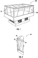
- FIG. 1 a perspective view of a refrigerated display case 100 is shown in FIG. 1 .
- This refrigerated display case 100 may be referred to as a "display case”, “freezer”, and/or “cabinet”.
- the refrigerated display case 100 may include multiple glass panels (e.g., a first glass panel 110 and a second glass panel 120) connected together to form corner assemblies 100 (shown in FIGs. 2 and 3 ). It should be appreciated that a single refrigerated display case 100 may include multiple corner assemblies.
- the corner assembly 100 includes a first glass panel 110, a second glass panel 120, a sealing element 130, and a tape 140. In certain instances, the corner assembly 100 may further include an external corner element 150.
- the first glass panel 110 includes an end region 114, an interior surface 115, and an exterior surface 116.
- the second glass panel 120 includes an end region 124, an interior surface 125, and an exterior surface 126.
- the sealing element 130 is disposed between the end region 114 of the fist glass panel 110 and the end region 124 of the second glass panel 120.
- the tape 140 may include an adhesive on an interior surface (not labeled, but to be viewed as the side of the tape 140 facing the exterior surface 116 of the first glass panel 110 and the exterior surface 126 of the second glass panel 120) to adhesively attach the interior surface of the tape 140 to the exterior surface 116 of the first glass panel 110 and the exterior surface 126 of the second glass panel 120.
- the tape 140 includes adhesive on only one side (e.g., only on the interior surface of the tape 140 and not on the exterior surface of the tape 140).
- first glass panel 110 and the second glass panel 120 each may respectively include a multi-layer insulated structure.
- a multi-layer insulated structure may be interpreted to mean that more than one pane of glass may be used to make up the structure.
- the first glass panel 110 and the second glass panel 120 may each respectively include multiple (e.g., at least two or three) panes of glass that are joined to each other via an intermediate layer.
- the multi-layer insulated structure of the first glass panel 110 may include three panes of glass 111, 112, 113, and the multi-layer insulated structure of the second glass panel 120 may include three panes of glass 121, 122, 123.
- the intermediate layer can be a thermoplastic material, such as polyvinyl butyral (PVB), ethylene vinyl acetate (EVA), polyurethane (PU), polyethylene terephthalate (PET), or multiple different layers thereof.
- PVB polyvinyl butyral
- EVA ethylene vinyl acetate
- PU polyurethane
- PET polyethylene terephthalate
- each pane of glass may be made of at least one of: flat glass, float glass, soda lime glass, quartz glass, or borosilicate glass. It should be appreciated that the thickness of each pane can vary. In certain instances, both the first glass panel 110 and the second glass panel 120 may have the same thickness (e.g., each may be approximately 28 mm thick).
- the corner assembly 100 may include an external corner element 150.
- the external corner element 150 may include a first end 151, a second end 152, an interior surface 153, and an exterior surface 154.
- the interior surface 153 of the external corner element 150 may be disposed over at least a portion of the exterior surface of the tape 140.
- at least one of the first end 151 and the second end 152 of the external corner element 150 include an adhesive (e.g., to adhesively attached the interior surface 153 of the external corner element 150 to the exterior surface of the tape 140).
- the external corner element 150 may be composed of a metal (e.g., stainless steel or aluminum) and may be configured to cover at least a portion of the exterior surface of the tape 140.
- the external corner element 150 may be a piece of metal flashing (e.g., being approximately between 0.5 mm and 2.5 mm thick). In certain instances, the external corner element 150 may be thicker at the first end 151 and the second end 152 (e.g., the metal may be doubled over, as shown in FIG. 3 ). It is envisioned that the tape 140 and the external corner element 150 may structurally support the corner assembly 100.
- the corner assembly 100 includes a sealing element 130.
- the sealing element 130 may include an internal portion 131 and a leg 132.
- the leg 132 may extend approximately perpendicular from the internal portion 131.
- the internal portion 131 may be disposed between the interior surface 115 of the first glass panel 110 and the interior surface 125 of the second glass panel 120, and the leg 131 may be disposed between the end region 114 of the first glass panel 110 and the end region 124 of the second glass panel 120.
- the internal portion 130 may be configured to tightly abut both interior surfaces 115, 125, and the leg 131 may be configured to tightly abut both end regions 114, 124 to create a seal between the first glass panel 110 and the second glass panel 120. Tightly abut may be interpreted to mean that, when correctly installed, there may not be a space between the sealing element 130 and the end region 114 of the first glass panel 110 or between the sealing element 130 and the end region 124 of the second glass panel 120.
- the sealing element 130 may be composed of a polyvinyl chloride (PVC).
- PVC typically comes in two basic forms: rigid (sometimes abbreviated as RPVC) and flexible.
- rigid sometimes abbreviated as RPVC
- flexible plasticizers, such as phthalates, may be added.
- the sealing element 130 may be designed to have the leg 132 more or less rigid than the internal portion 131.
- the leg 132 may be more rigid than the internal portion 131 to make it easier to assemble (e.g., the stiff structure may allow the sealing element 130 to be more easily slid down between the end region 114 of the first glass panel 110 and the end region 124 of the second glass panel 120).
- the leg 132 may be made of one or more sections of foam tape, which may be less rigid than the internal portion 132, which may be made of a silicone in certain instances. It should be appreciated that in certain instances the internal portion 131 may be more rigid than the leg 132.
- the sealing element 130 may be one continuous member in certain instances, it should be appreciated that in certain instances the sealing element 130 may be made of multiple, independent members adjacently configured to seal the end region 114 of the first glass panel 110 and the send region 124 of the second glass panel 120.
- the sealing element 130 is designed with minimal thickness.
- the leg 132 portion of the sealing element 130 may have a thickness less than half a thickness of the internal portion 131.
- the leg 132 portion sealing element 130 is about 1 mm thick (e.g., between 0.5 and 4 mm) and the internal portion 131 is about 2 mm thick (e.g., between 1 and 8 mm). This thickness of the sealing element 130, in combination with the way in which the first glass panel 110 and the second glass panel 120 align may make it possible to minimize the cross-sectional area of the corner assembly 100, which may enable more of the refrigerated display case 200 to be transparent.
- the end region 114 of the first glass panel 110 and the end region 124 of the second glass panel 120 each may respectively have a stepped structure.
- a stepped structure may be interpreted to mean that the end region 114, 124 may include multiple portions of differing widths.
- the stepped structure of the end region 114 of the first glass panel 110 may include a first portion 117 and a second portion 118.
- the first portion 117 may have a width greater than a width of the second portion 118 (e.g., the first portion 117 having a width of approximately 18 mm and the second portion 118 having a width of approximately 10 mm).
- the stepped structure of the end region 124 of the second glass panel 120 may also include a first portion 127 and a second portion 128.
- the first portion 127 has a width less than a width of the second portion 128.
- the stepped structure of the end regions 114, 124 may be complimentary to one another so as to form an approximately right angle at the intersection of the interior surfaces 115, 125 and the sealing element 130.
- the leg 132 of the sealing element 130 may have a complimentary stepped structure (e.g., similar to the stepped structure of the end regions 114, 124) so as to be able to be tightly abut the end regions 114, 124.
- the corner assembly 100 may include one or more heating element 161, 162.
- at least one of the end region 114 of the first glass panel 110 and the end region 124 of the second glass panel 120 may include a heating element 161, 162.
- this heating element 161, 162 may be configured as a tube (e.g., extending along at least a portion of the length of the corner assembly 100).
- This heating element 161, 162 may be an electrically powered tubular heating element.
- the corner assembly 100 includes a heating element 161 disposed in the first portion 117 of the stepped structure of the end region 114 of the first glass panel 110.
- the corner assembly 100 includes a heating element 162 disposed between the first portion 127 and the second portion 128 of the stepped structure of the end region of the second glass panel 120. It should be appreciated that although depicted herein to include a heating element 161, 162 disposed on each end region 114, 124, in certain instances, only one heating element 161, 162 (or no heating element) may be incorporated.
- the design and configuration of the corner assembly 100 make it possible to maximize the transparent area of a refrigerated display case 200, which may make the refrigerated display case 200 more aesthetically appealing and better suited to display chilled products (by minimizing the blocking of the goods). This design and configuration may also enable a fairly simplistic method of manufacture (e.g., by reducing the number of structural components needed on the interior of the refrigerated display case 200).
- the corner assembly 100 is externally structurally supported (e.g., through use of a tape 140 and/or external corner element 150), and has minimal internal components (e.g., only the internal portion 131 of the sealing element 130 is on the interior surface 115, 125 of the glass panels 110, 120).
- the method of manufacturing at least a portion of a refrigerated display case 200 is shown in FIG. 4 .
- This method may be done, for example, using exemplary corner assembly 100, as shown in FIGs. 2 and 3 .
- the refrigerated display case 200 includes at least a first glass panel 110 and a second glass panel 120, each respectively including an end region 114, 124, an interior surface 115, 125, and an exterior surface 116, 126.
- the method 800 provides step 810 for positioning the end region 114 of the first glass panel 110 approximately adjacent to the end region 124 of the second glass panel 120.
- a support e.g., a brace
- the method 800 provides step 820 for inserting a sealing element 130 between the end region 114 of the first glass panel 110 and the end region 124 of the second glass panel 120.
- the sealing element 130 may be slid from the top down between the first glass panel 110 and the second glass panel 120.
- the method 800 provides step 830 for adhesively attaching an interior surface of a tape 140 to the exterior surface 116 of the first glass panel 110 and the exterior surface 126 of the second glass panel 120.
- a single strip of tape 140 may be applied to the exterior surfaces 116, 126 so as to span the gap between the exterior surfaces 116, 126. It should be appreciated that a single piece of tape 140 may be used to span the entire length of the corner assembly 100.
- the method 800 provides step 840 for adhesively attaching an interior surface 153 of an external corner element 150 to at least a portion of an exterior surface of the tape 140.
Landscapes
- Engineering & Computer Science (AREA)
- General Engineering & Computer Science (AREA)
- Physics & Mathematics (AREA)
- Mechanical Engineering (AREA)
- Thermal Sciences (AREA)
- Chemical & Material Sciences (AREA)
- Combustion & Propulsion (AREA)
- Joining Of Glass To Other Materials (AREA)
- Refrigerator Housings (AREA)
Abstract
Description
- The invention relates to refrigerated display cases. More particularly, the invention relates to the corner assemblies used between two insulated glass panels of such refrigerated display cases.
- Refrigerated display cases (commonly referred to as "freezers" or "cabinets") are used in a variety of commercial settings. One key use of such refrigerated display cases is for retail display and vending. For example, refrigerated display cases can be used as a product presentation platform (e.g., in a grocery store) for chilled products. These refrigerated display cases commonly include a bottom surface and plurality of insulated glass panels extending around the perimeter of the bottom surface. The insulated glass panels form corner assemblies with one another. Conventionally, the corner assemblies are held together using at least one spacer. These spacers hold the insulated glass panels a distance from one another and produce a seal between the insulated glass panels. However, these spacers traditionally are not transparent. Consequently, the use of spacers within refrigerated display cases is not ideal, as the spacers not only take away from the aesthetic appeal of the refrigerated display case, but also reduce the ability of the consumer to see the products within the refrigerated display case.
- Accordingly, there remains a need for a corner assembly for a refrigerated display case with increased transparency when compared to traditional corner assemblies.
- According to a first aspect of the invention, a corner assembly including a first glass panel, a second glass panel, a sealing element, and a tape is provided. The first glass panel includes an end region, an interior surface, and an exterior surface. The second glass panel includes an end region, an interior surface, and an exterior surface. The sealing element is disposed between the end region of the first glass panel and the end region of the second glass panel. The tape includes an adhesive on an interior surface. The interior surface of the tape is adhesively attached to the exterior surface of the first glass panel and the exterior surface of the second glass panel.
- The first glass panel and the second glass panel may each respectively have a multi-layer insulated structure. The corner assembly may further include an external corner element with a first end, a second end, an interior surface, and an exterior surface. The interior surface of the external corner element may be disposed over at least a portion of the exterior surface of the tape.
- At least one of the first end and the second end of the external corner element may include an adhesive.
- The sealing element may include an internal portion and a leg, the leg extending approximately perpendicular from the internal portion.
- The leg may have a thickness less than half a thickness of the internal portion.
- The leg may have a rigidity greater than a rigidity of the internal portion.
- The internal portion may be disposed between the interior surface of the first glass panel and the interior surface of the second glass panel.
- The leg may be disposed between the end region of the first glass panel and the end region of the second glass panel.
- The end region of the first glass panel and the end region of the second glass panel may each respectively have a stepped structure.
- The stepped structure of the end region of the first glass panel may include a first portion and a second portion, the first portion having a width greater than a width of the second portion.
- The stepped structure of the end region of the second glass panel may include a first portion and a second portion, the first portion having a width less than a width of the second portion.
- At least one of the end region of the first glass panel and the end region of the second glass panel may include a heating element.
- A heating element may be disposed in the first portion of the stepped structure of the end region of the first glass panel.
- A heating element may be disposed between the first portion and the second portion of the stepped structure of the end region of the second glass panel.
- According to a second aspect of the invention, a method of manufacturing at least a portion of a refrigerated display case is provided. The refrigerated display case includes a first glass panel and a second glass panel, each respectively including an end region, an interior surface, and an exterior surface. The method includes a step for positioning an end region of the first glass panel approximately adjacent to the end region of the second glass panel. The method includes a step for inserting a sealing element between the end region of the first glass panel and the end region of the second glass panel. The method includes a step for adhesively attaching an interior surface of a tape to the exterior surface of the first glass panel and the exterior surface of the second glass panel.
- The method may further include a step for adhesively attaching an interior surface of an external corner element to at least a portion of an exterior surface of the tape.
- The sealing element may include an internal portion and a leg, the leg extending approximately perpendicular from the internal portion.
- The internal portion may be disposed between the interior surface of the first glass panel and the interior surface of the second glass panel, and the leg may be disposed between the end region of the first glass panel and the end region of the second glass panel.
- The end region of the first glass panel and the end region of the second glass panel may each respectively have a stepped structure.
- The following descriptions of the drawings should not be considered limiting in any way. With reference to the accompanying drawings, like elements are numbered alike:
-
FIG. 1 is a perspective view of a refrigerated display case. -
FIG. 2 is a perspective view of a corner assembly. -
FIG. 3 is a cross-sectional top view of a corner assembly. -
FIG. 4 is a flow diagram illustrating a method of manufacturing at least a portion of a refrigerated display case. - As will be described below, a corner assembly (e.g., for a refrigerated display case), and a method of manufacturing at least a portion of a refrigerated display case are provided. Although it is envisioned that the corner assembly could be used in any application in which two glass panels meet, for purposes of simplicity and brevity, the corner assembly is described in terms of being used in a refrigerated display case. The corner assembly is designed to have increased transparency when compared to traditional corner assemblies. For example, the corner assembly may have a reduced amount of spacing between the glass panels (e.g., when compared to traditional corner assemblies), which may maximize the amount of transparent area of the refrigerated display case. In addition to providing for increased transparency, the corner assembly may be, at least majorly, externally structurally supported (e.g., through use of a tape and/or external corner element), which may enable a fairly simplistic method of manufacture.
- With reference now to the Figures, a perspective view of a refrigerated
display case 100 is shown inFIG. 1 . This refrigerateddisplay case 100, in certain instances, may be referred to as a "display case", "freezer", and/or "cabinet". As shown inFIG. 1 , the refrigerateddisplay case 100 may include multiple glass panels (e.g., afirst glass panel 110 and a second glass panel 120) connected together to form corner assemblies 100 (shown inFIGs. 2 and3 ). It should be appreciated that a single refrigerateddisplay case 100 may include multiple corner assemblies. As shown inFIG. 3 , thecorner assembly 100 includes afirst glass panel 110, asecond glass panel 120, asealing element 130, and atape 140. In certain instances, thecorner assembly 100 may further include anexternal corner element 150. - As depicted in
FIG. 3 , thefirst glass panel 110 includes anend region 114, aninterior surface 115, and anexterior surface 116. Thesecond glass panel 120 includes anend region 124, aninterior surface 125, and anexterior surface 126. The sealingelement 130 is disposed between theend region 114 of thefist glass panel 110 and theend region 124 of thesecond glass panel 120. Thetape 140 may include an adhesive on an interior surface (not labeled, but to be viewed as the side of thetape 140 facing theexterior surface 116 of thefirst glass panel 110 and theexterior surface 126 of the second glass panel 120) to adhesively attach the interior surface of thetape 140 to theexterior surface 116 of thefirst glass panel 110 and theexterior surface 126 of thesecond glass panel 120. In certain instances, thetape 140 includes adhesive on only one side (e.g., only on the interior surface of thetape 140 and not on the exterior surface of the tape 140). - It should be appreciated that the
first glass panel 110 and thesecond glass panel 120 each may respectively include a multi-layer insulated structure. A multi-layer insulated structure may be interpreted to mean that more than one pane of glass may be used to make up the structure. For example, thefirst glass panel 110 and thesecond glass panel 120 may each respectively include multiple (e.g., at least two or three) panes of glass that are joined to each other via an intermediate layer. As shown inFIG. 3 , the multi-layer insulated structure of thefirst glass panel 110 may include three panes ofglass second glass panel 120 may include three panes ofglass first glass panel 110 and thesecond glass panel 120 may have the same thickness (e.g., each may be approximately 28 mm thick). - As mentioned above, the
corner assembly 100 may include anexternal corner element 150. Theexternal corner element 150 may include afirst end 151, asecond end 152, aninterior surface 153, and an exterior surface 154. Theinterior surface 153 of theexternal corner element 150 may be disposed over at least a portion of the exterior surface of thetape 140. In certain instances, at least one of thefirst end 151 and thesecond end 152 of theexternal corner element 150 include an adhesive (e.g., to adhesively attached theinterior surface 153 of theexternal corner element 150 to the exterior surface of the tape 140). It is envisioned that theexternal corner element 150 may be composed of a metal (e.g., stainless steel or aluminum) and may be configured to cover at least a portion of the exterior surface of thetape 140. For example, theexternal corner element 150 may be a piece of metal flashing (e.g., being approximately between 0.5 mm and 2.5 mm thick). In certain instances, theexternal corner element 150 may be thicker at thefirst end 151 and the second end 152 (e.g., the metal may be doubled over, as shown inFIG. 3 ). It is envisioned that thetape 140 and theexternal corner element 150 may structurally support thecorner assembly 100. - To seal the
first glass panel 110 and thesecond glass panel 120 together thecorner assembly 100 includes a sealingelement 130. The sealingelement 130 may include aninternal portion 131 and aleg 132. Theleg 132 may extend approximately perpendicular from theinternal portion 131. Theinternal portion 131 may be disposed between theinterior surface 115 of thefirst glass panel 110 and theinterior surface 125 of thesecond glass panel 120, and theleg 131 may be disposed between theend region 114 of thefirst glass panel 110 and theend region 124 of thesecond glass panel 120. For example, theinternal portion 130 may be configured to tightly abut bothinterior surfaces leg 131 may be configured to tightly abut bothend regions first glass panel 110 and thesecond glass panel 120. Tightly abut may be interpreted to mean that, when correctly installed, there may not be a space between the sealingelement 130 and theend region 114 of thefirst glass panel 110 or between the sealingelement 130 and theend region 124 of thesecond glass panel 120. - It is envisioned that the sealing
element 130 may be composed of a polyvinyl chloride (PVC). PVC typically comes in two basic forms: rigid (sometimes abbreviated as RPVC) and flexible. To make the PVC more flexible (i.e., less rigid) plasticizers, such as phthalates, may be added. It is envisioned that the sealingelement 130 may be designed to have theleg 132 more or less rigid than theinternal portion 131. For example, theleg 132 may be more rigid than theinternal portion 131 to make it easier to assemble (e.g., the stiff structure may allow thesealing element 130 to be more easily slid down between theend region 114 of thefirst glass panel 110 and theend region 124 of the second glass panel 120). In certain instances, theleg 132 may be made of one or more sections of foam tape, which may be less rigid than theinternal portion 132, which may be made of a silicone in certain instances. It should be appreciated that in certain instances theinternal portion 131 may be more rigid than theleg 132. Although described herein that the sealingelement 130 may be one continuous member in certain instances, it should be appreciated that in certain instances the sealingelement 130 may be made of multiple, independent members adjacently configured to seal theend region 114 of thefirst glass panel 110 and thesend region 124 of thesecond glass panel 120. - In certain instances, the sealing
element 130 is designed with minimal thickness. For example, theleg 132 portion of the sealingelement 130 may have a thickness less than half a thickness of theinternal portion 131. In certain instances, theleg 132portion sealing element 130 is about 1 mm thick (e.g., between 0.5 and 4 mm) and theinternal portion 131 is about 2 mm thick (e.g., between 1 and 8 mm). This thickness of the sealingelement 130, in combination with the way in which thefirst glass panel 110 and thesecond glass panel 120 align may make it possible to minimize the cross-sectional area of thecorner assembly 100, which may enable more of the refrigerateddisplay case 200 to be transparent. - It is envisioned that the
end region 114 of thefirst glass panel 110 and theend region 124 of thesecond glass panel 120 each may respectively have a stepped structure. A stepped structure may be interpreted to mean that theend region FIG. 3 , the stepped structure of theend region 114 of thefirst glass panel 110 may include afirst portion 117 and asecond portion 118. In certain instances, thefirst portion 117 may have a width greater than a width of the second portion 118 (e.g., thefirst portion 117 having a width of approximately 18 mm and thesecond portion 118 having a width of approximately 10 mm). The stepped structure of theend region 124 of thesecond glass panel 120 may also include afirst portion 127 and asecond portion 128. In certain instances, thefirst portion 127 has a width less than a width of thesecond portion 128. As shown the stepped structure of theend regions interior surfaces element 130. It should be appreciated that theleg 132 of the sealingelement 130 may have a complimentary stepped structure (e.g., similar to the stepped structure of theend regions 114, 124) so as to be able to be tightly abut theend regions - To prevent frost buildup along the
corner assembly 100, thecorner assembly 100 may include one ormore heating element end region 114 of thefirst glass panel 110 and theend region 124 of thesecond glass panel 120 may include aheating element FIG. 3 , thisheating element heating element corner assembly 100 includes aheating element 161 disposed in thefirst portion 117 of the stepped structure of theend region 114 of thefirst glass panel 110. In certain instances, thecorner assembly 100 includes aheating element 162 disposed between thefirst portion 127 and thesecond portion 128 of the stepped structure of the end region of thesecond glass panel 120. It should be appreciated that although depicted herein to include aheating element end region heating element 161, 162 (or no heating element) may be incorporated. - The design and configuration of the
corner assembly 100 make it possible to maximize the transparent area of arefrigerated display case 200, which may make therefrigerated display case 200 more aesthetically appealing and better suited to display chilled products (by minimizing the blocking of the goods). This design and configuration may also enable a fairly simplistic method of manufacture (e.g., by reducing the number of structural components needed on the interior of the refrigerated display case 200). As mentioned above, thecorner assembly 100 is externally structurally supported (e.g., through use of atape 140 and/or external corner element 150), and has minimal internal components (e.g., only theinternal portion 131 of the sealingelement 130 is on theinterior surface glass panels 110, 120). - The method of manufacturing at least a portion of a
refrigerated display case 200 is shown inFIG. 4 . This method may be done, for example, usingexemplary corner assembly 100, as shown inFIGs. 2 and3 . As described above, therefrigerated display case 200 includes at least afirst glass panel 110 and asecond glass panel 120, each respectively including anend region interior surface exterior surface method 800 providesstep 810 for positioning theend region 114 of thefirst glass panel 110 approximately adjacent to theend region 124 of thesecond glass panel 120. To position thefirst glass panel 110 and the second glass panel 120 a support (e.g., a brace) may be used. Themethod 800 providesstep 820 for inserting a sealingelement 130 between theend region 114 of thefirst glass panel 110 and theend region 124 of thesecond glass panel 120. For example, the sealingelement 130 may be slid from the top down between thefirst glass panel 110 and thesecond glass panel 120. Themethod 800 providesstep 830 for adhesively attaching an interior surface of atape 140 to theexterior surface 116 of thefirst glass panel 110 and theexterior surface 126 of thesecond glass panel 120. For example, a single strip oftape 140 may be applied to theexterior surfaces exterior surfaces tape 140 may be used to span the entire length of thecorner assembly 100. In certain instances, themethod 800 providesstep 840 for adhesively attaching aninterior surface 153 of anexternal corner element 150 to at least a portion of an exterior surface of thetape 140. - The use of the terms "a" and "and" and "the" and similar referents, in the context of describing the invention, are to be construed to cover both the singular and the plural, unless otherwise indicated herein or cleared contradicted by context. The use of any and all example, or exemplary language (e.g., "such as", "e.g.", "for example", etc.) provided herein is intended merely to better illuminate the invention and does not pose a limitation on the scope of the invention unless otherwise claimed. No language in the specification should be construed as indicating any non-claimed elements as essential to the practice of the invention.
- While the present invention has been described with reference to an exemplary embodiment or embodiments, it will be understood by those skilled in the art that various changes may be made and equivalents may be substituted for elements thereof without departing from the scope of the invention as set out in the appended claims. Therefore, it is intended that the invention as set out in the appended claims not be limited to the particular embodiment disclosed as the best mode contemplated for carrying out this invention, but that the invention will include all embodiments falling within the scope of the claims.
Claims (15)
- A corner assembly (100) comprising:a first glass panel (110) comprising an end region (114), an interior surface (115), and an exterior surface (116);a second glass panel (120) comprising an end region (124), an interior surface (125), and an exterior surface (126);a sealing element (130) disposed between the end region (114) of the first glass panel and the end region (124) of the second glass panel; anda tape (140) comprising an adhesive on an interior surface, the interior surface of the tape adhesively attached to the exterior surface (116) of the first glass panel (110) and the exterior surface (126) of the second glass panel (120).
- The corner assembly (100) of claim 1, wherein the first glass panel (110) and the second glass panel (120) each respectively comprise a multi-layer insulated structure.
- The corner assembly (100) of claim 1 or 2, further comprising an external corner element (150) comprising a first end (151), a second end (152), an interior surface (153), and an exterior surface (154), the interior surface (153) of the external corner element disposed over at least a portion of an exterior surface of the tape (140).
- The corner assembly (100) of claim 3, wherein at least one of the first end (151) and the second end (152) of the external corner element (150) comprise an adhesive.
- The corner assembly (100) of any preceding claim, wherein the sealing element (130) comprises an internal portion (131) and a leg (132), the leg extending approximately perpendicular from the internal portion, optionally:
wherein the leg (132) comprises a thickness less than half a thickness of the internal portion (131), and/or:
wherein the leg (132) comprises a rigidity greater than a rigidity of the internal portion (131). - The corner assembly of claim 5, wherein the internal portion (131) is disposed between the interior surface (114) of the first glass panel and the interior surface (124) of the second glass panel, and/or:
wherein the leg (132) is disposed between the end region (114) of the first glass panel and the end region (124) of the second glass panel. - The corner assembly of any preceding claim, wherein the end region (114) of the first glass panel (110) and the end region (124) of the second glass panel (120) each respectively comprise a stepped structure, optionally:
wherein the stepped structure of the end region (114) of the first glass panel comprises a first portion (117) and a second portion (118), the first portion comprising a width greater than a width of the second portion, and/or:
wherein the stepped structure of the end region (124) of the second glass panel comprises a first portion (127) and a second portion (128), the first portion comprising a width less than a width of the second portion. - The corner assembly of any preceding claim, wherein at least one of the end region (114) of the first glass panel (110) and the end region (124) of the second glass panel (120) comprise a heating element (161, 162).
- The corner assembly of claim 7, wherein a heating element (161) is disposed in the first portion (117) of the stepped structure of the end region (114) of the first glass panel (110).
- The corner assembly of claim 7 or 9, wherein a heating element (162) is disposed between the first portion (127) and the second portion (128) of the stepped structure of the end region (124) of the second glass panel (120).
- A method of manufacturing at least a portion of a refrigerated display case (200), the refrigerated display case comprising a first glass panel (110) and a second glass panel (120), each respectively comprising an end region (114, 124), an interior surface (115, 125), and an exterior surface (116, 126), the method comprising:positioning the end region (114) of the first glass panel (110) approximately adjacent to the end region (124) of the second glass panel (120);inserting a sealing element (130) between the end region (114) of the first glass panel and the end region (124) of the second glass panel; andadhesively attaching an interior surface of a tape (140) to the exterior surface (116) of the first glass panel and the exterior surface (126) of the second glass panel.
- The method of claim 11, further comprising adhesively attaching an interior surface (153) of an external corner element (150) to at least a portion of an exterior surface of the tape (140).
- The method of claim 11 or 12, wherein the sealing element (130) comprises an internal portion (131) and a leg (132), the leg extending approximately perpendicular from the internal portion.
- The method of claim 13, wherein the internal portion (131) is disposed between the interior surface (115) of the first glass panel and the interior surface (125) of the second glass panel, and the leg (132) is disposed between the end region (114) of the first glass panel and the end region (124) of the second glass panel.
- The method of any of claims 11 to 14, wherein the end region (114) of the first glass panel and the end region (124) of the second glass panel each respectively comprise a stepped structure.
Applications Claiming Priority (1)
| Application Number | Priority Date | Filing Date | Title |
|---|---|---|---|
| US202062705486P | 2020-06-30 | 2020-06-30 |
Publications (2)
| Publication Number | Publication Date |
|---|---|
| EP3933315A1 true EP3933315A1 (en) | 2022-01-05 |
| EP3933315B1 EP3933315B1 (en) | 2023-08-23 |
Family
ID=76708130
Family Applications (1)
| Application Number | Title | Priority Date | Filing Date |
|---|---|---|---|
| EP21182552.6A Active EP3933315B1 (en) | 2020-06-30 | 2021-06-29 | Refrigerated display case and method of manufacturing thereof |
Country Status (2)
| Country | Link |
|---|---|
| EP (1) | EP3933315B1 (en) |
| CN (1) | CN113854783A (en) |
Cited By (1)
| Publication number | Priority date | Publication date | Assignee | Title |
|---|---|---|---|---|
| EP4099870B1 (en) * | 2020-02-03 | 2024-02-28 | Mondial Framec S.r.l. | Refrigerated display cabinet |
Citations (4)
| Publication number | Priority date | Publication date | Assignee | Title |
|---|---|---|---|---|
| US3721366A (en) * | 1970-12-21 | 1973-03-20 | B Battershall | Glass tank construction |
| US4660903A (en) * | 1984-06-29 | 1987-04-28 | Sanden Corporation | Temperature controlled display case |
| EP2979588A1 (en) * | 2014-07-31 | 2016-02-03 | Goppion S.p.A. | Showcase having shaped and glued walls made of a transparent material |
| US20160242571A1 (en) * | 2015-02-20 | 2016-08-25 | Structural Concepts Corporation | Insulated glass enclosure for refrigerated display case |
-
2021
- 2021-06-29 EP EP21182552.6A patent/EP3933315B1/en active Active
- 2021-06-30 CN CN202110732101.8A patent/CN113854783A/en active Pending
Patent Citations (4)
| Publication number | Priority date | Publication date | Assignee | Title |
|---|---|---|---|---|
| US3721366A (en) * | 1970-12-21 | 1973-03-20 | B Battershall | Glass tank construction |
| US4660903A (en) * | 1984-06-29 | 1987-04-28 | Sanden Corporation | Temperature controlled display case |
| EP2979588A1 (en) * | 2014-07-31 | 2016-02-03 | Goppion S.p.A. | Showcase having shaped and glued walls made of a transparent material |
| US20160242571A1 (en) * | 2015-02-20 | 2016-08-25 | Structural Concepts Corporation | Insulated glass enclosure for refrigerated display case |
Cited By (1)
| Publication number | Priority date | Publication date | Assignee | Title |
|---|---|---|---|---|
| EP4099870B1 (en) * | 2020-02-03 | 2024-02-28 | Mondial Framec S.r.l. | Refrigerated display cabinet |
Also Published As
| Publication number | Publication date |
|---|---|
| CN113854783A (en) | 2021-12-31 |
| EP3933315B1 (en) | 2023-08-23 |
Similar Documents
| Publication | Publication Date | Title |
|---|---|---|
| EP3450892B1 (en) | Refrigerated display case door and refrigerated display case | |
| US6606832B2 (en) | Apparatus and methods of forming a display case door and frame | |
| US10791849B2 (en) | Insulating glazing unit, in particular for a climate chamber | |
| US9661940B2 (en) | Glass element for a cabinet having a refrigerated chamber | |
| US9389013B2 (en) | Thermal frame for a refrigerated enclosure | |
| US10704318B2 (en) | Insulating glazing unit, in particular for a climate chamber | |
| KR100606428B1 (en) | Climate Condition Recycling Cabinet | |
| US20090072679A1 (en) | Glass door for refrigerated merchandiser | |
| JP2017515082A5 (en) | ||
| US20120324806A1 (en) | High R-Value, Removable and Transparent Window Insulation Panels | |
| EP2584135A2 (en) | Insulated glass unit | |
| EP1629749B1 (en) | Multi-pane glass assembly for a refrigerated display case | |
| EP3933315B1 (en) | Refrigerated display case and method of manufacturing thereof | |
| US20160367046A1 (en) | Insulated glass enclosure for refrigerated display case | |
| JPH09228748A (en) | Multi-layer glass shoji, rotating window and sliding window | |
| GB2569337A (en) | Roof lights and windows | |
| EP3730731A1 (en) | Improved transparent double-glazing unit | |
| US20250179866A1 (en) | Glazing | |
| WO2012163748A1 (en) | Showcase for controlled-temperature exhibitors | |
| US10760327B2 (en) | Insulating glazing, in particular for a temperature-controlled piece of furniture | |
| JPH04240378A (en) | Door for refrigerator | |
| JPH04136168U (en) | Refrigerated, frozen case | |
| CN111706240A (en) | Embedded multi-cavity full-warm frame built-in sun-shading energy-saving hollow glass product | |
| JP2007188480A (en) | Partition plate for vending machine, method for manufacturing the same, and vending machine | |
| BR112018068388B1 (en) | INSULATING GLAZING ESPECIALLY FOR CLIMATE CHAMBER, DOOR AND AIR CONDITIONED UNIT |
Legal Events
| Date | Code | Title | Description |
|---|---|---|---|
| PUAI | Public reference made under article 153(3) epc to a published international application that has entered the european phase |
Free format text: ORIGINAL CODE: 0009012 |
|
| STAA | Information on the status of an ep patent application or granted ep patent |
Free format text: STATUS: THE APPLICATION HAS BEEN PUBLISHED |
|
| AK | Designated contracting states |
Kind code of ref document: A1 Designated state(s): AL AT BE BG CH CY CZ DE DK EE ES FI FR GB GR HR HU IE IS IT LI LT LU LV MC MK MT NL NO PL PT RO RS SE SI SK SM TR |
|
| B565 | Issuance of search results under rule 164(2) epc |
Effective date: 20211129 |
|
| STAA | Information on the status of an ep patent application or granted ep patent |
Free format text: STATUS: REQUEST FOR EXAMINATION WAS MADE |
|
| 17P | Request for examination filed |
Effective date: 20220323 |
|
| RBV | Designated contracting states (corrected) |
Designated state(s): AL AT BE BG CH CY CZ DE DK EE ES FI FR GB GR HR HU IE IS IT LI LT LU LV MC MK MT NL NO PL PT RO RS SE SI SK SM TR |
|
| RIC1 | Information provided on ipc code assigned before grant |
Ipc: F16B 12/46 20060101ALI20230213BHEP Ipc: A47F 3/04 20060101ALI20230213BHEP Ipc: F25D 23/00 20060101AFI20230213BHEP |
|
| GRAP | Despatch of communication of intention to grant a patent |
Free format text: ORIGINAL CODE: EPIDOSNIGR1 |
|
| STAA | Information on the status of an ep patent application or granted ep patent |
Free format text: STATUS: GRANT OF PATENT IS INTENDED |
|
| INTG | Intention to grant announced |
Effective date: 20230324 |
|
| GRAS | Grant fee paid |
Free format text: ORIGINAL CODE: EPIDOSNIGR3 |
|
| GRAA | (expected) grant |
Free format text: ORIGINAL CODE: 0009210 |
|
| STAA | Information on the status of an ep patent application or granted ep patent |
Free format text: STATUS: THE PATENT HAS BEEN GRANTED |
|
| AK | Designated contracting states |
Kind code of ref document: B1 Designated state(s): AL AT BE BG CH CY CZ DE DK EE ES FI FR GB GR HR HU IE IS IT LI LT LU LV MC MK MT NL NO PL PT RO RS SE SI SK SM TR |
|
| REG | Reference to a national code |
Ref country code: GB Ref legal event code: FG4D |
|
| REG | Reference to a national code |
Ref country code: CH Ref legal event code: EP |
|
| REG | Reference to a national code |
Ref country code: IE Ref legal event code: FG4D |
|
| REG | Reference to a national code |
Ref country code: DE Ref legal event code: R096 Ref document number: 602021004457 Country of ref document: DE |
|
| REG | Reference to a national code |
Ref country code: NL Ref legal event code: FP |
|
| REG | Reference to a national code |
Ref country code: LT Ref legal event code: MG9D |
|
| REG | Reference to a national code |
Ref country code: AT Ref legal event code: MK05 Ref document number: 1603041 Country of ref document: AT Kind code of ref document: T Effective date: 20230823 |
|
| PG25 | Lapsed in a contracting state [announced via postgrant information from national office to epo] |
Ref country code: GR Free format text: LAPSE BECAUSE OF FAILURE TO SUBMIT A TRANSLATION OF THE DESCRIPTION OR TO PAY THE FEE WITHIN THE PRESCRIBED TIME-LIMIT Effective date: 20231124 |
|
| PG25 | Lapsed in a contracting state [announced via postgrant information from national office to epo] |
Ref country code: IS Free format text: LAPSE BECAUSE OF FAILURE TO SUBMIT A TRANSLATION OF THE DESCRIPTION OR TO PAY THE FEE WITHIN THE PRESCRIBED TIME-LIMIT Effective date: 20231223 |
|
| PG25 | Lapsed in a contracting state [announced via postgrant information from national office to epo] |
Ref country code: SE Free format text: LAPSE BECAUSE OF FAILURE TO SUBMIT A TRANSLATION OF THE DESCRIPTION OR TO PAY THE FEE WITHIN THE PRESCRIBED TIME-LIMIT Effective date: 20230823 Ref country code: RS Free format text: LAPSE BECAUSE OF FAILURE TO SUBMIT A TRANSLATION OF THE DESCRIPTION OR TO PAY THE FEE WITHIN THE PRESCRIBED TIME-LIMIT Effective date: 20230823 Ref country code: PT Free format text: LAPSE BECAUSE OF FAILURE TO SUBMIT A TRANSLATION OF THE DESCRIPTION OR TO PAY THE FEE WITHIN THE PRESCRIBED TIME-LIMIT Effective date: 20231226 Ref country code: NO Free format text: LAPSE BECAUSE OF FAILURE TO SUBMIT A TRANSLATION OF THE DESCRIPTION OR TO PAY THE FEE WITHIN THE PRESCRIBED TIME-LIMIT Effective date: 20231123 Ref country code: LV Free format text: LAPSE BECAUSE OF FAILURE TO SUBMIT A TRANSLATION OF THE DESCRIPTION OR TO PAY THE FEE WITHIN THE PRESCRIBED TIME-LIMIT Effective date: 20230823 Ref country code: LT Free format text: LAPSE BECAUSE OF FAILURE TO SUBMIT A TRANSLATION OF THE DESCRIPTION OR TO PAY THE FEE WITHIN THE PRESCRIBED TIME-LIMIT Effective date: 20230823 Ref country code: IS Free format text: LAPSE BECAUSE OF FAILURE TO SUBMIT A TRANSLATION OF THE DESCRIPTION OR TO PAY THE FEE WITHIN THE PRESCRIBED TIME-LIMIT Effective date: 20231223 Ref country code: HR Free format text: LAPSE BECAUSE OF FAILURE TO SUBMIT A TRANSLATION OF THE DESCRIPTION OR TO PAY THE FEE WITHIN THE PRESCRIBED TIME-LIMIT Effective date: 20230823 Ref country code: GR Free format text: LAPSE BECAUSE OF FAILURE TO SUBMIT A TRANSLATION OF THE DESCRIPTION OR TO PAY THE FEE WITHIN THE PRESCRIBED TIME-LIMIT Effective date: 20231124 Ref country code: FI Free format text: LAPSE BECAUSE OF FAILURE TO SUBMIT A TRANSLATION OF THE DESCRIPTION OR TO PAY THE FEE WITHIN THE PRESCRIBED TIME-LIMIT Effective date: 20230823 Ref country code: AT Free format text: LAPSE BECAUSE OF FAILURE TO SUBMIT A TRANSLATION OF THE DESCRIPTION OR TO PAY THE FEE WITHIN THE PRESCRIBED TIME-LIMIT Effective date: 20230823 |
|
| P01 | Opt-out of the competence of the unified patent court (upc) registered |
Effective date: 20240119 |
|
| PG25 | Lapsed in a contracting state [announced via postgrant information from national office to epo] |
Ref country code: PL Free format text: LAPSE BECAUSE OF FAILURE TO SUBMIT A TRANSLATION OF THE DESCRIPTION OR TO PAY THE FEE WITHIN THE PRESCRIBED TIME-LIMIT Effective date: 20230823 |
|
| PG25 | Lapsed in a contracting state [announced via postgrant information from national office to epo] |
Ref country code: ES Free format text: LAPSE BECAUSE OF FAILURE TO SUBMIT A TRANSLATION OF THE DESCRIPTION OR TO PAY THE FEE WITHIN THE PRESCRIBED TIME-LIMIT Effective date: 20230823 |
|
| PG25 | Lapsed in a contracting state [announced via postgrant information from national office to epo] |
Ref country code: SM Free format text: LAPSE BECAUSE OF FAILURE TO SUBMIT A TRANSLATION OF THE DESCRIPTION OR TO PAY THE FEE WITHIN THE PRESCRIBED TIME-LIMIT Effective date: 20230823 Ref country code: RO Free format text: LAPSE BECAUSE OF FAILURE TO SUBMIT A TRANSLATION OF THE DESCRIPTION OR TO PAY THE FEE WITHIN THE PRESCRIBED TIME-LIMIT Effective date: 20230823 Ref country code: ES Free format text: LAPSE BECAUSE OF FAILURE TO SUBMIT A TRANSLATION OF THE DESCRIPTION OR TO PAY THE FEE WITHIN THE PRESCRIBED TIME-LIMIT Effective date: 20230823 Ref country code: EE Free format text: LAPSE BECAUSE OF FAILURE TO SUBMIT A TRANSLATION OF THE DESCRIPTION OR TO PAY THE FEE WITHIN THE PRESCRIBED TIME-LIMIT Effective date: 20230823 Ref country code: DK Free format text: LAPSE BECAUSE OF FAILURE TO SUBMIT A TRANSLATION OF THE DESCRIPTION OR TO PAY THE FEE WITHIN THE PRESCRIBED TIME-LIMIT Effective date: 20230823 Ref country code: CZ Free format text: LAPSE BECAUSE OF FAILURE TO SUBMIT A TRANSLATION OF THE DESCRIPTION OR TO PAY THE FEE WITHIN THE PRESCRIBED TIME-LIMIT Effective date: 20230823 Ref country code: SK Free format text: LAPSE BECAUSE OF FAILURE TO SUBMIT A TRANSLATION OF THE DESCRIPTION OR TO PAY THE FEE WITHIN THE PRESCRIBED TIME-LIMIT Effective date: 20230823 |
|
| REG | Reference to a national code |
Ref country code: DE Ref legal event code: R097 Ref document number: 602021004457 Country of ref document: DE |
|
| PLBE | No opposition filed within time limit |
Free format text: ORIGINAL CODE: 0009261 |
|
| STAA | Information on the status of an ep patent application or granted ep patent |
Free format text: STATUS: NO OPPOSITION FILED WITHIN TIME LIMIT |
|
| 26N | No opposition filed |
Effective date: 20240524 |
|
| PG25 | Lapsed in a contracting state [announced via postgrant information from national office to epo] |
Ref country code: SI Free format text: LAPSE BECAUSE OF FAILURE TO SUBMIT A TRANSLATION OF THE DESCRIPTION OR TO PAY THE FEE WITHIN THE PRESCRIBED TIME-LIMIT Effective date: 20230823 |
|
| PG25 | Lapsed in a contracting state [announced via postgrant information from national office to epo] |
Ref country code: BG Free format text: LAPSE BECAUSE OF FAILURE TO SUBMIT A TRANSLATION OF THE DESCRIPTION OR TO PAY THE FEE WITHIN THE PRESCRIBED TIME-LIMIT Effective date: 20230823 |
|
| PG25 | Lapsed in a contracting state [announced via postgrant information from national office to epo] |
Ref country code: BG Free format text: LAPSE BECAUSE OF FAILURE TO SUBMIT A TRANSLATION OF THE DESCRIPTION OR TO PAY THE FEE WITHIN THE PRESCRIBED TIME-LIMIT Effective date: 20230823 |
|
| PG25 | Lapsed in a contracting state [announced via postgrant information from national office to epo] |
Ref country code: MC Free format text: LAPSE BECAUSE OF FAILURE TO SUBMIT A TRANSLATION OF THE DESCRIPTION OR TO PAY THE FEE WITHIN THE PRESCRIBED TIME-LIMIT Effective date: 20230823 |
|
| REG | Reference to a national code |
Ref country code: CH Ref legal event code: PL |
|
| PG25 | Lapsed in a contracting state [announced via postgrant information from national office to epo] |
Ref country code: LU Free format text: LAPSE BECAUSE OF NON-PAYMENT OF DUE FEES Effective date: 20240629 |
|
| PG25 | Lapsed in a contracting state [announced via postgrant information from national office to epo] |
Ref country code: IE Free format text: LAPSE BECAUSE OF NON-PAYMENT OF DUE FEES Effective date: 20240629 |
|
| PG25 | Lapsed in a contracting state [announced via postgrant information from national office to epo] |
Ref country code: BE Free format text: LAPSE BECAUSE OF NON-PAYMENT OF DUE FEES Effective date: 20240630 Ref country code: CH Free format text: LAPSE BECAUSE OF NON-PAYMENT OF DUE FEES Effective date: 20240630 |
|
| REG | Reference to a national code |
Ref country code: BE Ref legal event code: MM Effective date: 20240630 |
|
| PGFP | Annual fee paid to national office [announced via postgrant information from national office to epo] |
Ref country code: GB Payment date: 20250620 Year of fee payment: 5 |
|
| PGFP | Annual fee paid to national office [announced via postgrant information from national office to epo] |
Ref country code: NL Payment date: 20250618 Year of fee payment: 5 |
|
| PGFP | Annual fee paid to national office [announced via postgrant information from national office to epo] |
Ref country code: FR Payment date: 20250624 Year of fee payment: 5 |
|
| PGFP | Annual fee paid to national office [announced via postgrant information from national office to epo] |
Ref country code: DE Payment date: 20250827 Year of fee payment: 5 |
|
| PGFP | Annual fee paid to national office [announced via postgrant information from national office to epo] |
Ref country code: IT Payment date: 20250630 Year of fee payment: 5 |
|
| PG25 | Lapsed in a contracting state [announced via postgrant information from national office to epo] |
Ref country code: CY Free format text: LAPSE BECAUSE OF FAILURE TO SUBMIT A TRANSLATION OF THE DESCRIPTION OR TO PAY THE FEE WITHIN THE PRESCRIBED TIME-LIMIT; INVALID AB INITIO Effective date: 20210629 |
|
| PG25 | Lapsed in a contracting state [announced via postgrant information from national office to epo] |
Ref country code: HU Free format text: LAPSE BECAUSE OF FAILURE TO SUBMIT A TRANSLATION OF THE DESCRIPTION OR TO PAY THE FEE WITHIN THE PRESCRIBED TIME-LIMIT; INVALID AB INITIO Effective date: 20210629 |