EP3933288A1 - Air conditioner indoor unit - Google Patents
Air conditioner indoor unit Download PDFInfo
- Publication number
- EP3933288A1 EP3933288A1 EP19927145.3A EP19927145A EP3933288A1 EP 3933288 A1 EP3933288 A1 EP 3933288A1 EP 19927145 A EP19927145 A EP 19927145A EP 3933288 A1 EP3933288 A1 EP 3933288A1
- Authority
- EP
- European Patent Office
- Prior art keywords
- detection device
- component
- air
- indoor unit
- conditioner indoor
- Prior art date
- Legal status (The legal status is an assumption and is not a legal conclusion. Google has not performed a legal analysis and makes no representation as to the accuracy of the status listed.)
- Granted
Links
Images



Classifications
-
- F—MECHANICAL ENGINEERING; LIGHTING; HEATING; WEAPONS; BLASTING
- F24—HEATING; RANGES; VENTILATING
- F24F—AIR-CONDITIONING; AIR-HUMIDIFICATION; VENTILATION; USE OF AIR CURRENTS FOR SCREENING
- F24F11/00—Control or safety arrangements
- F24F11/70—Control systems characterised by their outputs; Constructional details thereof
-
- F—MECHANICAL ENGINEERING; LIGHTING; HEATING; WEAPONS; BLASTING
- F24—HEATING; RANGES; VENTILATING
- F24F—AIR-CONDITIONING; AIR-HUMIDIFICATION; VENTILATION; USE OF AIR CURRENTS FOR SCREENING
- F24F1/00—Room units for air-conditioning, e.g. separate or self-contained units or units receiving primary air from a central station
- F24F1/0007—Indoor units, e.g. fan coil units
- F24F1/0011—Indoor units, e.g. fan coil units characterised by air outlets
-
- F—MECHANICAL ENGINEERING; LIGHTING; HEATING; WEAPONS; BLASTING
- F24—HEATING; RANGES; VENTILATING
- F24F—AIR-CONDITIONING; AIR-HUMIDIFICATION; VENTILATION; USE OF AIR CURRENTS FOR SCREENING
- F24F11/00—Control or safety arrangements
- F24F11/30—Control or safety arrangements for purposes related to the operation of the system, e.g. for safety or monitoring
- F24F11/32—Responding to malfunctions or emergencies
- F24F11/36—Responding to malfunctions or emergencies to leakage of heat-exchange fluid
-
- F—MECHANICAL ENGINEERING; LIGHTING; HEATING; WEAPONS; BLASTING
- F24—HEATING; RANGES; VENTILATING
- F24F—AIR-CONDITIONING; AIR-HUMIDIFICATION; VENTILATION; USE OF AIR CURRENTS FOR SCREENING
- F24F2110/00—Control inputs relating to air properties
- F24F2110/50—Air quality properties
- F24F2110/65—Concentration of specific substances or contaminants
-
- F—MECHANICAL ENGINEERING; LIGHTING; HEATING; WEAPONS; BLASTING
- F24—HEATING; RANGES; VENTILATING
- F24F—AIR-CONDITIONING; AIR-HUMIDIFICATION; VENTILATION; USE OF AIR CURRENTS FOR SCREENING
- F24F2140/00—Control inputs relating to system states
- F24F2140/20—Heat-exchange fluid temperature
-
- Y—GENERAL TAGGING OF NEW TECHNOLOGICAL DEVELOPMENTS; GENERAL TAGGING OF CROSS-SECTIONAL TECHNOLOGIES SPANNING OVER SEVERAL SECTIONS OF THE IPC; TECHNICAL SUBJECTS COVERED BY FORMER USPC CROSS-REFERENCE ART COLLECTIONS [XRACs] AND DIGESTS
- Y02—TECHNOLOGIES OR APPLICATIONS FOR MITIGATION OR ADAPTATION AGAINST CLIMATE CHANGE
- Y02B—CLIMATE CHANGE MITIGATION TECHNOLOGIES RELATED TO BUILDINGS, e.g. HOUSING, HOUSE APPLIANCES OR RELATED END-USER APPLICATIONS
- Y02B30/00—Energy efficient heating, ventilation or air conditioning [HVAC]
- Y02B30/70—Efficient control or regulation technologies, e.g. for control of refrigerant flow, motor or heating
Definitions
- the present application relates to the field of air conditioning technologies, and more particularly to an air conditioner indoor unit.
- R290 i.e., propane
- propane which can be directly obtained from liquefied petroleum gas.
- propane has risk of combustion or explosion when encountering a heat source or open flame under certain conditions, and the air conditioner indoor unit using this type of refrigerant has potential safety hazards.
- the present disclosure seeks to solve at least one of the problems existing in the related art to at least some extent.
- an objective of the present disclosure provides an air conditioner indoor unit.
- the air conditioner indoor unit includes an air outlet; an air outlet component provided at the air outlet and configured to change outlet airflow effect of the air outlet; a heat exchange component and an air supplying component, the air supplying component being configured to make air enter the air conditioner indoor unit and exchange heat with the heat exchange component, and then make the air, after exchanging heat, flow to the air outlet component, to be blown out through the air outlet; and a detection component including at least either a first detection device or a second detection device, the first detection device being mounted on the air outlet component and configured to detect refrigerant leakage condition of the air conditioner indoor unit, the second detection device being provided at the heat exchange component and configured to detect refrigerant leakage.
- the air conditioner indoor unit by provision of the detection component, can improve operational safety of the air conditioner indoor unit.
- the first detection device includes a detection body and a transmission wire
- the transmission wire electrically couples the detection body to an electric control board of the air conditioner indoor unit
- the air outlet component defines a wiring trough for wiring of the transmission wire
- the first detection device includes a detection body and a power storage member, the power storage member is electrically coupled to the detection body, and the detection body and an electric control board of the air conditioner indoor unit are provided with no transmission wire therebetween.
- the air outlet component includes an air guiding plate component
- the first detection device is provided at the air guiding plate component
- the air guiding plate component includes: an outer air guiding plate movably provided at the air outlet and configured to open and close the air outlet and regulate an air blowing direction of the air outlet.
- the outer air guiding plate includes: a body part extending in a length direction of the air outlet; and mounting parts provided at two ends of a length of the body part, the outer air guiding plate being mounted through the mounting parts, at least either the body part or the mounting parts being provided with the first detection device.
- the first detection device include a semiconductor gas sensor provided at a working face of a middle of the body part, and/or, the first detection device includes an infrared transmitter and an infrared receiver, the infrared transmitter being provided on an inner surface of one mounting part, the infrared receiver being provided on an inner surface of the other mounting part.
- the air guiding plate component further includes: an inner air guiding plate provided at an inner side of the outer air guiding plate and configured to regulate the air blowing direction of the air outlet, at least either the outer air guiding plate or the inner air guiding plate is provided with the first detection device.
- the air outlet component includes a louver component including a mounting plate, a louver and a coupling rod, a plurality of louvers are provided and arranged on the mounting plate, the coupling rod is coupled to the louvers, and at least one among the mounting plate, the louvers and the coupling rod is provided with the first detection device.
- the air outlet component includes an opening/closing door component including an opening/closing door body and a vent hole defined in the opening/closing door body, and the first detection device is provided on an inner surface of the opening/closing door body.
- the heat exchange component includes a refrigerant tube, at least one second detection device is provided at a bend segment of the refrigerant tube, and/or, at least one second detection device is provided at a weld of the refrigerant tube.
- the heat exchange component includes a fin, and at least one second detection device is mounted on the fin.
- At least one second detection device is provided below the heat exchange component.
- the second detection device includes a first type detection device directly or indirectly mounted to the heat exchange component and in touch with the heat exchange component.
- the second detection device includes a second type detection device directly or indirectly mounted to the heat exchange component and spaced apart from the heat exchange component.
- the second detection device includes at least either a gas sensor or a temperature sensor.
- the air supplying component is located downstream of the heat exchange component
- the second detection device is located upstream of the air supplying component
- the second detection device is located downstream of the heat exchange component
- some air conditioner indoor units use combustible refrigerant (such as refrigerant R29, i.e., propane).
- refrigerant R29 i.e., propane
- these air conditioner indoor units in the related art generally have a refrigerant leakage detection device to prevent danger.
- the refrigerant leakage detection device in the related art is affected by the mounting position and has poor detection effectiveness.
- the present application proposes an air conditioner indoor unit 100 which can detect the refrigerant leakage relatively in time.
- the air conditioner indoor unit 1000 may include an air outlet 12, an air outlet component 2, an air supplying component 5 and a heat exchange component 6.
- the air supplying component 5 is used to make air enter the air conditioner indoor unit 1000 and exchange heat with the heat exchange component 6, and then make the air after heat exchange flow to the air outlet component 2, to be blown out through the air outlet 12.
- the air outlet component 2 is provided at the air outlet 12 and used to change outlet airflow effect of the air outlet 12, such as outlet airflow direction, outlet airflow rate, outlet airflow volume, etc.
- a first detection device 3 is mounted on the air outlet component 2.
- the air conditioner indoor unit 1000 further includes at least one of the first detection device 3 and a second detection device 4.
- the first detection device 3 details about the first detection device 3 are first introduced, and then details about the second detection device 4 are introduced.
- the first detection device 3 is used to detect refrigerant leakage condition of the air conditioner indoor unit 1000.
- the first detection device 3 may be located near the air outlet 12.
- concentration of refrigerant detected by the first detection device 3 is concentration of refrigerant blown from an inside of air conditioner indoor unit 1000 to environment.
- leaked refrigerant may be thoroughly mixed with the air and flow to the air outlet 12, and concentration of refrigerant at the air outlet 12 can represent current average concentration of the leaked refrigerant inside the air conditioner indoor unit 1000 more accurately, to speculate risk of refrigerant leakage accurately according to concentration data detected by the first detection device 3.
- the first detection device 3 since the first detection device 3 is located near the air outlet 12, it is convenient for a user or maintenance personnel to detach and replace the first detection device 3, and it is ensured that the first detection device 3 is always located in a main airflow path, and the refrigerant leakage detection device 3 may always detect leakage condition of the refrigerant. Therefore, the refrigerant leakage can be detected not only when the air supplying component 5 is in operation, but also when the air supplying component 5 is stopped.
- the air conditioner indoor unit 1000 has different specific types, and for example it may be an integrated air conditioner (such as a window air conditioner, a portable air conditioner, etc.) or a split air conditioner (such as a split wall-mounted air conditioner, a split cabinet air conditioner, etc.).
- the air conditioner indoor unit 1000 at least includes an indoor unit portion adapted to be provided indoors (such as an indoor unit of the window air conditioner, an indoor unit of the split wall-mounted air conditioner, an indoor unit of the split cabinet air conditioner, etc.). Since the indoor unit portion is located indoors and indoor environment is relatively closed, there is a higher risk of exposure and the indoor unit portion may be provided with the first detection device 3, to improve use safety of the air conditioner indoor unit 1000.
- the air conditioner indoor unit 1000 may also include an outdoor unit portion adapted to be provided outdoors.
- the outdoor unit portion may also be provided with the first detection device 3, to further improve use safety of the air conditioner indoor unit 1000.
- the indoor unit portion including the above-described heat exchange component 1, air outlet component 2 and first detection device 3 is taken as an example, and those skilled in the art can readily appreciate specific implementations of the outdoor unit portion including the above-described heat exchange component 1, air outlet component 2 and first detection device 3 after reading the following technical solutions.
- the air outlet component 2 when the air outlet component 2 is applied to the indoor unit portion of the split wall-mounted air conditioner, the air outlet component 2 may include an air guiding plate component 21, or include an air guiding plate and a louver component 22 located at an inner side of the air guiding plate component 21.
- the air outlet component 2 when the air outlet component 2 is applied to the indoor unit portion of the split wall-mounted air conditioner, the air outlet component 2 may include an air guiding plate component 21, or include an air guiding plate and a louver component 22 located at an inner side of the air guiding plate component 21.
- the air outlet component 2 when the air outlet component 2 is applied to the indoor unit portion of the split cabinet air conditioner, the air outlet component 2 may include an opening/closing door component 23 and a louver component 22 located at an inner side of the opening/closing door component 23.
- the present application is not limited to this, when the application scenario is specifically determined, those skilled in the art can know what the air outlet component 2 specifically refers to; and as long as the component is provided near the air outlet 12 and used to change the outlet airflow effect (such as outlet airflow direction, outlet airflow rate, etc.), it may be construed as the air outlet component 2 indicated herein.
- the number of the first detection device 3 according to embodiments of the present application is not limited, and may be specifically set according to actual requirement. Additionally, when a plurality of first detection devices 3 are provided, the mounting positions of the plurality of first detection devices 3 may be set on the same air outlet component 2, and the plurality of first detection devices 3 may also be provided on different air outlet components 2. For example, some first detection devices 3 may be provided on the louver component 22, some first detection devices 3 may be provided on the air guiding plate component 21, which is not elaborated herein. Hereinafter, some specific mounting solutions of the first detection device 3 according to embodiments of the present application will be described.
- the air outlet component 2 may include the air guiding plate component 21.
- the air guiding plate component 21 includes an outer air guiding plate 211.
- the outer air guiding plate 211 is movably provided at the air outlet 12, and is used to open and close the air outlet 12 and adjust an air blowing direction of the air outlet 12. That is to say, the outer air guiding plate 211 at least has two functions, one is to adjust the outlet airflow direction, and the other is to open and close the air outlet 12.
- the first detection device 3 is provided to the air guiding plate component 21, that is, the first detection device 3 is mounted on the air guiding plate component 21, but not limited to being mounted on the outer air guiding plate 211.
- the first detection device 3 has higher detection accuracy and can perform detection when the air outlet component 2 is working or stopped.
- the outer air guiding plate 211 may include a body part 211a and a mounting part 211b.
- the body part 211a extends in a length direction of the air outlet 12.
- the length direction of the air outlet 12 may be a horizontal direction, and in this case the length direction of the body part 211a is also the horizontal direction.
- the length direction of the air outlet 12 may be a vertical direction, and in this case the length direction of the body part 211a is also the vertical direction.
- the mounting parts 211b are provided at two ends of the length of the body part 211a and used to mount the outer air guiding plate 211. That is, the outer air guiding plate 211 is mounted through the mounting parts 211b.
- the first detection device 3 may be mounted on the outer air guiding plate 211.
- the first detection device 3 may be mounted on at least one of the body part 211a and the mounting parts 211b.
- the first detection device 3 can be flexibly mounted according to different specific model selections of the first detection device 3.
- the first detection device 3 may be mounted on the body part 211a.
- the first detection device 3 may include a semiconductor gas sensor 3a, and the semiconductor gas sensor 3a is provided on a working face of a middle of the body part 211a.
- the mounting space is ample, and the mounting and maintenance are convenient; furthermore mixing effect at the middle of the outer air guiding plate 211 is more uniform, and the detected concentration of refrigerant is closer to the average.
- the first detection device 3 may also be provided on a wording face of an end of the length of the body part 211a, and thus closer to a wielding position of tubing of the heat exchange component 6, to detect leakage problem more quickly.
- the semiconductor gas sensor 3a may be a solution that "includes a detection body 31 and a power storage member 33", to avoid defining a wiring trough 20 in the body part 211a.
- the semiconductor gas sensor 3a may also be a solution that "includes a detection body 31 and a transmission wire 32".
- the first detection device 3 may also be mounted on the mounting part 211b.
- the first detection device 3 includes an infrared transmitter 3b and an infrared receiver 3c, the infrared transmitter 3b is provided on an inner surface of one mounting part 211b, and the infrared receiver 3c is provided on an inner surface of the other mounting part 211b.
- the infrared transmitter 3b and the infrared receiver 3c may be spaced apart in the length direction of the air outlet 12, refrigerant leakage detection can be performed for larger area, and the detected value is further closer to the average.
- each of the infrared transmitter 3b and the infrared receiver 3c may be a solution that "includes a detection body 31 and a transmission wire 32".
- the transmission wire 32 may be directly led out from the mounting parts 211b at two sides of the body part 211a.
- the mounting part 211b includes a rotating shaft
- the transmission wire 32 may be directly led out along the vicinity rotating shaft or from an interior of the rotating shaft, etc., to reduce the costs.
- each of the infrared transmitter 3b and the infrared receiver 3c may also be a solution that "includes a detection body 31 and a power storage member 33", to avoid interference with the transmission wire 32 when the air outlet component 2 moves.
- the present application is not limited to this, when the first detection device 3 includes the infrared transmitter 3b and the infrared receiver 3c, the infrared transmitter 3b and the infrared receiver 3c may also be provided on any two support structures 213 (referring to FIG. 3 ) at an inner side of the outer air guiding plate 211, to be spaced apart in the length direction of the air outlet 12, which is not elaborated herein.
- each of the body part 211a and the mounting parts 211b may also be provided with the first detection device 3, and in this case, model selection and mounting mode of the first detection device 3 may refer to the above description, which are not limited herein.
- fixing and mounting mode of the first detection device 3 is not limited. For example, mounting modes such as snap-fit, screws, etc. can be employed, as long as the mounting and detachment are easy.
- the first detection device 3 is not limited to being provided on the outer air guiding plate 211.
- the air guiding plate component 21 also includes an inner air guiding plate 212
- the inner air guiding plate 212 may also be provided at the inner side of the outer air guiding plate 211, and used to adjust the air blowing direction of the air outlet 12, and at least one of the outer air guiding plate 211 and the inner air guiding plate 212 is provided with the first detection device 3.
- flexible mounting of the first detection device 3 can be realized.
- coupling mode of the outer air guiding plate 211 and the inner air guiding plate 212 is not limited, such as fixed coupling (e.g., coupling via the support structure 213 described above) or relatively movable coupling, which is not limited herein.
- the air outlet component 2 may include a louver component 22.
- the louver component 22 includes a mounting plate 221, a louver 222 and a coupling rod 223.
- a plurality of louvers 222 are provided and arranged on the mounting plate 221, the coupling rod 223 is coupled to the louvers 222, and at least one of the mounting plate 221, the louvers 222 and the coupling rod 223 is provided with the first detection device 3.
- the first detection device 3 on the louver component 22, it can be closer to the interior of the air conditioner indoor unit 1000, and refrigerant leakage problem can be detected more quickly, to eradicate explosion problem due to the refrigerant more quickly and completely.
- the air outlet component 2 includes an opening/closing door component 23.
- the opening/closing door component 23 includes an opening/closing door body 231 and a vent hole 232 defined in the opening/closing door body 231, and when the opening/closing door body 231 is in a state of closing the air outlet 12, the airflow blown out from the air outlet component 2 can pass through the vent hole 232 in the opening/closing door body 231 to be blown out, to weaken the strength of the airflow blown out and reach a breezeless or soft air blowing effect.
- an inner surface of the opening/closing door body 231 may be provided with the first detection device 3.
- the first detection device 3 can be prevented from being exposed, and the first detection device 3 can be protected, to ensure service life and operational reliability of the first detection device 3.
- the first detection device 3 may include a detection body 31 and a transmission wire 32.
- the transmission wire 32 electrically couples the detection body 31 to an electric control board 7 of the air conditioner indoor unit 1000.
- the electric control board 7 can accordingly regulate the air conditioner indoor unit 1000 based on the date fed back by the first detection device 3, to reduce the explosion risk and improve safety of the air conditioner indoor unit 1000.
- the air outlet component 2 (including the air guiding plate component 21, the louver component 22 and the opening/closing door component 23, as described above) may also have the wiring trough 20 for wiring of the transmission wire 32, to facilitate arrangement of the wire and improve neatness and safety of the air conditioner indoor unit 1000.
- the first detection device 3 may include a detection body 31 and a power storage member 33 (such as an ordinary battery, a rechargeable battery, etc.), and the power storage member 33 is electrically coupled to the detection body 31.
- the first detection device 3 may get power from its own power storage member 33 to carry out the detection work.
- the first detection device 3 and the electric control board 7 may be provided with no transmission wire 32 between them, application of transmission wire 32 is avoided, the costs are reduced, and the structural simplicity and assembly efficiency are improved.
- the first detection device 3 may also communicate with the electric control board 7 via wireless transmission mode, the electric control board 7 can accordingly regulate the air conditioner indoor unit 1000 based on the date fed back by the first detection device 3 (specific control method can refer to the following description, but it is not limited to this), to reduce the explosion risk and improve safety of the air conditioner indoor unit 1000.
- the air conditioner indoor unit 1000 is a horizontal split wall-mounted air conditioner indoor unit
- the air guiding plate component 21 extends in the horizontal direction and horizontal sides thereof are fixed with the infrared transmitter 3b and the infrared receiver 3c by a certain structural form respectively, and the infrared transmitter 3b and the infrared receiver 3c are both located at a side of the air guiding plate component 21 facing the air outlet 12.
- a coupling line direction of the infrared transmitter 3b and the infrared receiver 3c and the length direction of the air guiding plate component 21 are each a horizontal direction and parallel to each other.
- An infrared signal transmitted by the infrared transmitter 3b can be received by the infrared receiver 3c, the signal can be transmitted to the electric control board 7 through the transmission wire 32, and the electric control board 7 can analyze concentration of refrigerant at the area through which the infrared signal passed according to the strength of the detected signal.
- the first detection device 3 in the present embodiment can detect the concentration of refrigerant accurately whether the air guiding plate component 21 is in a closed state and in this case the air supplying component 5 is stopped, or the air guiding plate component 21 is in an open state and in this case the air supplying component 5 is in operation. Additionally, in the present embodiment, since density of the refrigerant is greater than that of the air, and the air conditioner air outlet 12 is below the indoor heat exchange component 1, the first detection device 3 can detect the refrigerant leakage not only when the air supplying component 5 is in operation but also when the air supplying component 5 is stopped.
- the air conditioner indoor unit 100 may include a housing 1, a heat exchange component 2, an air supplying component 3 and a second detection device 4.
- the housing 1 has an air passage 11 therein, the heat exchange component 2 is provided in the housing 1 and used to exchange heat with the airflow in the air passage 11, and the air supplying component 3 is provided in the housing 1 and used to ventilate the air passage 11.
- an interior of the housing 1 of the air conditioner indoor unit 100 has the air passage 11, the heat exchange component 2, the air supplying component 3 and the second detection device 4, the air supplying component 3 makes the air flow from an outside of the housing 1 into the air passage 11 inside the housing 1 and make airflow in the air passage 11 be discharged to the outside of the housing 1; the heat exchange component 2 exchanges heat with the airflow in the air passage 11 to change the temperature of the airflow passing through the air passage 11, and further to change the environmental temperature after the airflow passing through the air passage 11 is discharged to the outside of the housing 1.
- the second detection device 4 is provided at the heat exchange component 2 and used to detect the refrigerant leakage.
- the second detection device 4 being provided at the heat exchange component 2 means that the second detection device 4 is provided close to the heat exchange component 2, or touches the heat exchanger 2, to ensure that the second detection device 4 is located on or near the heat exchange component 2.
- the inventors found in the real life that, the refrigerant passes through an interior of the heat exchange component 2 of the air conditioner indoor unit 100, and the refrigerant is easy to leak near the heat exchange component 2. Therefore, by providing the second detection device 4 near the heat exchange component 2 and close to the above-described refrigerant leakage position, the air conditioner indoor unit 100 according to the present application can detect the refrigerant leakage relatively timely and effectively and improve operational safety of the air conditioner indoor unit 100.
- the heat exchange component 2 may include a refrigerant tube 61, and at least one second detection device 4 (such as a first sensor 41 illustrated in FIG. 10 ) is provided at a bend segment 611 of the refrigerant tube 61.
- the refrigerant tube 61 of the heat exchange component 2 has the bend segment 611, and the bend segment 611 is formed by bending straight segment into the bend segment in a bending process, and thus an outside wall of at a bend of the bend segment 611 is thin and even has cracks, etc., and potential hazards of the refrigerant leakage exists.
- the bend segment 611 of the refrigerant tube 61 is more prone to the refrigerant leakage than the straight segment of the refrigerant tube 61, and by providing at least one second detection device 4 near the bend segment 611 to detect whether the refrigerant leakage occurs at the bend segment 611 of the refrigerant tube 61, the second detection device 4 can detect the refrigerant leakage as soon as possible, i.e., more quickly, to improve the operational safety of the air conditioner indoor unit 100.
- the heat exchange component 2 may include a plurality of refrigerant tubes 61.
- the heat exchange component 2 when the heat exchange component 2 is a fin-and-tube heat exchange component, the heat exchange component 2 includes stacked fins 62 and the refrigerant tube 61 penetrating the fins 62.
- a portion of the refrigerant tube 61 penetrating an inside of the fin 62 is the straight segment of the refrigerant tube 61, and portions of the refrigerant tube 61 located at two ends of the fins 62 in a stacked direction (such as a left-right direction illustrated in FIGS. 11 and 12 ) are mostly the bend segments 611.
- the first sensor 41 may be provided at the bend segment 611 of a left side of the fin 62, and as illustrated in FIG. 12 , the first sensor 41 may also be provided at the bend segment 611 of a right side of the fin 62.
- the heat exchange component 2 may include the refrigerant tube 61, and at least one second detection device 4(such as a second sensor 42 illustrated in FIG. 10 ) is provided at a weld 612 of the refrigerant tube.
- the refrigerant tube 61 of the heat exchange component 2 mostly employs welding as the coupling mode during arrangement. During welding the refrigerant tube 61, internal defects such as slag inclusion, porosity, etc.
- the weld 612 of the refrigerant tube 61 is more prone to the refrigerant leakage than other positions of the refrigerant tube 61, and by providing at least one second detection device 4 near the weld 612, to at least detect whether the refrigerant leakage occurs at the weld 612 of the refrigerant tube 61, the second detection device 4 can detect the refrigerant leakage as soon as possible, i.e., more quickly, to improve the operational safety of the air conditioner indoor unit 100.
- the heat exchange component 2 may include a plurality of refrigerant tubes 61, and adjacent straight segments of the refrigerant tube 61 on the heat exchange component 2 usually form a weld 612 between them (such as a weld 612a illustrated in FIG. 11 ). Furthermore, the refrigerant tube 61 and other refrigerant tubes except for the heat exchange component 2 (such as an outdoor refrigerant coupling tube) usually form a weld 612 between them (such as a weld 612b illustrated in FIG. 11 ), at least one second detection device 4 may be provided near at least one of the above welds 612.
- the heat exchange component 2 when the heat exchange component 2 is a fin-and-tube heat exchange component, the heat exchange component 2 may include stacked fins 62 and the refrigerant tube 61 penetrating the fins 62.
- a portion of the refrigerant tube 61 penetrating an inside of the fin 62 is the straight segment of the refrigerant tube 61, and portions of the refrigerant tube 61 located at two ends of the fins 62 in a stacked direction (such as a left-right direction illustrated in FIGS. 11 and 12 ) are mostly the bend segments 611.
- the bend segment 611 and the straight segment at a side of the fin 62 in the stacked direction (such as a right side illustrated in FIGS.
- the bend segment 611 and the straight segment at the other side of the fin 62 in the stacked direction may be formed by bending one same tube.
- the second sensor 42 in the second detection device 4 may be provided at the weld 612 at the right side of the fin 62.
- the heat exchange component 2 may include a fin 62, and at least one second detection device 4(such as a third sensor 43 illustrated in the figure) is mounted on the fin 62.
- the heat exchange component 2 and the third sensor 43 can constitute an integral component to simplify the structure, reduce the costs and improve mounting efficiency; furthermore relative position of the third sensor 43 and the heat exchange component 2 can be more reliable, to avoid displacement, deviation, etc. of the third sensor 43 relative to the heat exchange component 2 due to vibration, etc. during transportation or use to the greatest extent and to improve operational stability and reliability of the third sensor 43.
- At least one second detection device 4 may be provided below the heat exchange component 2.
- the inventors found in real life that, since the density of the refrigerant is greater than the density of the air, the leaked refrigerant will gradually diffuse downwards under its own gravity, and the corresponding second detection device 4 (such as the fourth sensor 44 illustrated in FIG. 13 ) can detect the refrigerant leakage more reliably, to improve the operational safety of the air conditioner indoor unit 100.
- the at least one second detection device 4 such as the fourth sensor 44 illustrated in FIG. 13 below the heat exchange component 2
- the fourth sensor 44 may be closer to a collected position of the refrigerant, and the fourth sensor 44 can detect the refrigerant leakage more reliably to improve the operational safety of the air conditioner indoor unit 100.
- the type of the air conditioner indoor unit 100 is not limited.
- the air conditioner indoor unit 100 may be a horizontal wall-mounted air conditioner, and in this case, the heat exchange component 2 may extend horizontally, and the fourth sensor 44 may be located at a lower side of a width of the fin 62 (for example, in this case the fourth sensor 44 may be mounted on the fin 62 of the heat exchange component 2).
- the air conditioner indoor unit 100 may also be a vertical cabinet air conditioner, and in this case, the heat exchange component 2 may extend in the vertical direction, and the fourth sensor 44 may be located at a lower side of the length of the fin 62 (for example, in this case the fourth sensor 44 may be mounted on the refrigerant tube 61 of the heat exchange component 2).
- the second detection device 4 may include a first type detection device 4a.
- the first type detection device 4a is directly or indirectly mounted to the heat exchange component 2 and in touch with the heat exchange component 2.
- the first type detection device 4a By making the first type detection device 4a be directly or indirectly mounted on the heat exchange component 2 and in touch with the heat exchange component 2, positioning difficulty can be reduced and assembly efficiency can be improved; furthermore, relative position of the first type detection device 4a and the heat exchange component 2 can be more reliable, to avoid displacement, deviation, etc. of the first type detection device 4a relative to the heat exchange component 2 due to vibration, etc. during transportation or use to the greatest extent, and to improve detection stability and reliability of the first type detection device 4a.
- any one of the above-described first sensor 41, second sensor 42, third sensor 43, and fourth sensor 44 may be the first type detection device 4a.
- the second detection device 4 may include a second type detection device 4b.
- the second type detection device 4b is directly or indirectly mounted to the heat exchange component 2 and spaced apart from the heat exchange component 2, heat exchange efficiency of the heat exchange component 2 can be ensured, and relative position of the second type detection device 4b and the heat exchange component 2 can be more reliable, to avoid displacement, deviation, etc. of the second type detection device 4b relative to the heat exchange component 2 due to vibration, etc. during transportation or use to the greatest extent, and to improve detection stability and reliability of the second type detection device 4b.
- any one of the above-described first sensor 41, second sensor 42, third sensor 43, and fourth sensor 44 may be the second type detection device 4b.
- the second detection device 4 being mounted to the heat exchange component 2 means that the second detection device 4 may be mounted at any location of the heat exchange component 2, such as the above-described bend 211, weld 612, fin 62, etc.
- coupling of the second detection device 4 and the heat exchange component 2 is not limited. For example, they may be directly fixed. For instance, each of the second detection device 4 and the heat exchange component 2 is provided with a coupling lug or other structures, to realize the direct coupling, improve the assembly efficiency, and reduce the number of the parts and components.
- they may be indirectly fixed.
- the second detection device 4 may be indirectly fixed on the heat exchange component 2 by a support component 8, etc., to reduce structural complexity of the second detection device 4 and the heat exchange component 2 and reduce the costs.
- a distance L between each second detection device 4 and the heat exchange component 2 is smaller than or equal to 20mm.
- L may be 5mm, 10mm, 15mm, 20mm, etc.
- the second detection device 4 may be closer to the heat exchange component 2, the second detection device 4 can detect the refrigerant leakage as soon as possible, i.e., more quickly, to improve the operational safety of the air conditioner indoor unit 100.
- the distance L between the second detection device 4 and the heat exchange component 2 may also be greater than or equal to 20mm, such as 25mm, 30mm, 35mm, etc.
- the second detection device 4 may include at least one of a gas sensor and a temperature sensor.
- each of the above-described first sensor 41, second sensor 42, third sensor 43, and fourth sensor 44 may be a gas sensor or temperature sensor.
- the air supplying component 3 is located downstream of the heat exchange component 2
- the second detection device 4 is located upstream of the air supplying component 3
- the second detection device 4 is located downstream of the heat exchange component 2. That is, the second detection device 4 is provided between the air supplying component 3 and the heat exchange component 2.
- the second detection device 4 can detect the refrigerant leakage as soon as possible, i.e., more quickly, to improve the operational safety of the air conditioner indoor unit 100.
- upstream and downstream is determined according to a flow direction of the airflow, a direction of a position where the airflow passes first is the upstream, and a direction of a position where the airflow passes later is the downstream.
- the air conditioner indoor unit 100 may also have other characteristics.
- the housing 1 may also have an air outlet 12 and an air inlet 13, the air outlet 12 may be located in a lower front of the housing 1, and the air inlet 13 may be located in a top of the housing 1, which however is not limited to this.
- the control method may include the following steps: detecting refrigerant leakage by a second detection device 4 (that is, the second detection device 4 acquires a signal); determining that the refrigerant leakage occurs when a change rate of a signal value (i.e., change quantity of the signal per unit time) output by the second detection device 4 is greater than a preset threshold (such as leakage threshold or danger threshold described below), and in this case a corresponding action may be performed to avoid the danger.
- a preset threshold such as leakage threshold or danger threshold described below
- concentration of refrigerant detected by the second detection device 4 in the air conditioner indoor unit 100 is greater than the leakage threshold, it is determined that in this case the refrigerant leakage occurs, and an indoor fan is started to diffuse the refrigerant faster (in this case if the air conditioner indoor unit 100 is in the on and operation state, the speed of the indoor fan can be increased), to realize mandatory discharge; when concentration of refrigerant detected by the second detection device 4 is greater than the danger threshold, the power supply of the air conditioner indoor unit 100 is cut off, to avoid potential safety hazards caused by continuous power supply.
- a structure in which a first feature is “on” or “below” a second feature may include an embodiment in which the first feature is in direct contact with the second feature, and may also include an embodiment in which the first feature and the second feature are not in direct contact with each other, but are contacted via an additional feature formed therebetween.
Landscapes
- Engineering & Computer Science (AREA)
- Chemical & Material Sciences (AREA)
- Combustion & Propulsion (AREA)
- Mechanical Engineering (AREA)
- General Engineering & Computer Science (AREA)
- Air Conditioning Control Device (AREA)
- Air Filters, Heat-Exchange Apparatuses, And Housings Of Air-Conditioning Units (AREA)
Abstract
Description
- This application is based on and claims priority to
Chinese Patent Application Serial No. 201910354030.5, filed on April 29, 2019 Chinese Patent Application Serial No. 201920613842.2, filed on April 29, 2019 Chinese Patent Application Serial No. 201920776157.1, filed on May 27, 2019 - The present application relates to the field of air conditioning technologies, and more particularly to an air conditioner indoor unit.
- With application and development of air conditioning technologies, more and more cooling systems employ a refrigerant R290, i.e., propane, which can be directly obtained from liquefied petroleum gas. However, the propane has risk of combustion or explosion when encountering a heat source or open flame under certain conditions, and the air conditioner indoor unit using this type of refrigerant has potential safety hazards.
- The present disclosure seeks to solve at least one of the problems existing in the related art to at least some extent.
- To this end, an objective of the present disclosure provides an air conditioner indoor unit.
- The air conditioner indoor unit according to embodiments of the present application includes an air outlet; an air outlet component provided at the air outlet and configured to change outlet airflow effect of the air outlet; a heat exchange component and an air supplying component, the air supplying component being configured to make air enter the air conditioner indoor unit and exchange heat with the heat exchange component, and then make the air, after exchanging heat, flow to the air outlet component, to be blown out through the air outlet; and a detection component including at least either a first detection device or a second detection device, the first detection device being mounted on the air outlet component and configured to detect refrigerant leakage condition of the air conditioner indoor unit, the second detection device being provided at the heat exchange component and configured to detect refrigerant leakage.
- The air conditioner indoor unit according to embodiments of the present application, by provision of the detection component, can improve operational safety of the air conditioner indoor unit.
- In some embodiments, the first detection device includes a detection body and a transmission wire, the transmission wire electrically couples the detection body to an electric control board of the air conditioner indoor unit, and the air outlet component defines a wiring trough for wiring of the transmission wire.
- In some embodiments, the first detection device includes a detection body and a power storage member, the power storage member is electrically coupled to the detection body, and the detection body and an electric control board of the air conditioner indoor unit are provided with no transmission wire therebetween.
- In some embodiments, the air outlet component includes an air guiding plate component, the first detection device is provided at the air guiding plate component, and the air guiding plate component includes: an outer air guiding plate movably provided at the air outlet and configured to open and close the air outlet and regulate an air blowing direction of the air outlet.
- In some embodiments, the outer air guiding plate includes: a body part extending in a length direction of the air outlet; and mounting parts provided at two ends of a length of the body part, the outer air guiding plate being mounted through the mounting parts, at least either the body part or the mounting parts being provided with the first detection device.
- In some embodiments, the first detection device include a semiconductor gas sensor provided at a working face of a middle of the body part, and/or, the first detection device includes an infrared transmitter and an infrared receiver, the infrared transmitter being provided on an inner surface of one mounting part, the infrared receiver being provided on an inner surface of the other mounting part.
- In some embodiments, the air guiding plate component further includes: an inner air guiding plate provided at an inner side of the outer air guiding plate and configured to regulate the air blowing direction of the air outlet, at least either the outer air guiding plate or the inner air guiding plate is provided with the first detection device.
- In some embodiments, the air outlet component includes a louver component including a mounting plate, a louver and a coupling rod, a plurality of louvers are provided and arranged on the mounting plate, the coupling rod is coupled to the louvers, and at least one among the mounting plate, the louvers and the coupling rod is provided with the first detection device.
- In some embodiments, the air outlet component includes an opening/closing door component including an opening/closing door body and a vent hole defined in the opening/closing door body, and the first detection device is provided on an inner surface of the opening/closing door body.
- In some embodiments, the heat exchange component includes a refrigerant tube, at least one second detection device is provided at a bend segment of the refrigerant tube, and/or, at least one second detection device is provided at a weld of the refrigerant tube.
- In some embodiments, the heat exchange component includes a fin, and at least one second detection device is mounted on the fin.
- In some embodiments, at least one second detection device is provided below the heat exchange component.
- In some embodiments, the second detection device includes a first type detection device directly or indirectly mounted to the heat exchange component and in touch with the heat exchange component.
- In some embodiments, the second detection device includes a second type detection device directly or indirectly mounted to the heat exchange component and spaced apart from the heat exchange component.
- In some embodiments, the second detection device includes at least either a gas sensor or a temperature sensor.
- In some embodiments, the air supplying component is located downstream of the heat exchange component, the second detection device is located upstream of the air supplying component, and the second detection device is located downstream of the heat exchange component.
- Additional aspects and advantages of embodiments of present disclosure will be given in part in the following descriptions, become apparent in part from the following descriptions, or be learned from the practice of the embodiments of the present disclosure.
-
-
FIG. 1 is a sectional view of an air conditioner indoor unit according to an embodiment of the present application. -
FIG. 2 is a sectional view of an air conditioner indoor unit according to an embodiment of the present application. -
FIG. 3 is a perspective view of an air guiding plate component according to an embodiment of the present application. -
FIG. 4 is a side view of the air guiding plate component illustrated inFIG. 3 . -
FIG. 5 is a perspective view of an air conditioner indoor unit according to an embodiment of the present application. -
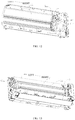
FIG. 6 is an assembly view of an air guiding plate component and a first detection device according to an embodiment of the present application. -
FIG. 7 is an assembly view of an air guiding plate component and a first detection device according to an embodiment of the present application. -
FIG. 8 is an assembly view of an air guiding plate component and a first detection device according to an embodiment of the present application. -
FIG. 9 is a side sectional view of an air conditioner indoor unit according to another embodiment of the present application. -
FIG. 10 is a view showing an internal structure of an air conditioner indoor unit according to another embodiment of the present application. -
FIG. 11 is a view showing an internal structure of an air conditioner indoor unit according to another embodiment of the present application. -
FIG. 12 is a view showing an internal structure of an air conditioner indoor unit according to another embodiment of the present application. -
FIG. 13 is a view showing an internal structure of an air conditioner indoor unit according to another embodiment of the present application. -
FIG. 14 is a perspective view of an air conditioner indoor unit according to an embodiment of the present application. -
FIG. 15 is a control flow chart of an air conditioner indoor unit according to an embodiment of the present application. -
- air conditioner
indoor unit 1000; - housing 1;
air passage 11;air outlet 12;air inlet 13; -
air outlet component 2;-
wiring trough 20; - air guiding
plate component 21; outerair guiding plate 211; innerair guiding plate 212;support structure 213;
body part 211a; mountingpart 211b; -
louver component 22;mounting plate 221;louver 222;coupling rod 223; - opening/closing
door component 23; opening/closingdoor body 231;vent hole 232;
-
-
first detection device 3;-
detection body 31;transmission wire 32; power storage member 33; - semiconductor gas sensor 3a;
infrared transmitter 3b; infrared receiver 3c;
-
-
second detection device 4; first type detection device 4a; secondtype detection device 4b; -
first sensor 41;second sensor 42;third sensor 43;fourth sensor 44;air supplying component 5; -
heat exchange component 6;refrigerant tube 61;bend segment 611;weld 612;fin 62; - electric control board 7; support component 8.
- Embodiments of the present application will be described in detail and examples of the embodiments will be illustrated in the drawings, where same or similar reference numerals are used to indicate same or similar members or members with same or similar functions. The embodiments described herein with reference to drawings are explanatory, illustrative, and intended to generally understand the present application. The embodiments shall not be construed to limit the present application.
- The following disclosure provides many different embodiments or examples to realize different structures of the present application. To simplify the disclosure of the present application, components and configurations in particular examples are elaborated. Of course, they are illustrative, and are not intended to limit the present application. Additionally, the present application can repeat reference numerals and/or letters in different examples. This repeat is for the purpose of simplicity and clarity, which shall not be constructed to indicate the relationships among various embodiments and/or configurations. In addition, the present application provides examples of various specific processes and materials, but applicability of other processes and/or utilization of other materials are conceivable for those skilled in the art.
- In the related art, some air conditioner indoor units use combustible refrigerant (such as refrigerant R29, i.e., propane). When leaked refrigerant of the air conditioner indoor unit reaches a certain concentration, explosion may occur. Hence, these air conditioner indoor units in the related art generally have a refrigerant leakage detection device to prevent danger. However, the refrigerant leakage detection device in the related art is affected by the mounting position and has poor detection effectiveness. In view of this, the present application proposes an air conditioner
indoor unit 100 which can detect the refrigerant leakage relatively in time. - Hereinafter, an air conditioner
indoor unit 1000 according to embodiments of the present application is described with reference to the accompanying drawings. - As illustrated in
FIGS. 1 and 2 , the air conditionerindoor unit 1000 according to embodiments of the present application may include anair outlet 12, anair outlet component 2, anair supplying component 5 and aheat exchange component 6. Theair supplying component 5 is used to make air enter the air conditionerindoor unit 1000 and exchange heat with theheat exchange component 6, and then make the air after heat exchange flow to theair outlet component 2, to be blown out through theair outlet 12. Theair outlet component 2 is provided at theair outlet 12 and used to change outlet airflow effect of theair outlet 12, such as outlet airflow direction, outlet airflow rate, outlet airflow volume, etc. Afirst detection device 3 is mounted on theair outlet component 2. - The air conditioner
indoor unit 1000 according to embodiments of the present application further includes at least one of thefirst detection device 3 and asecond detection device 4. Hereinafter, details about thefirst detection device 3 are first introduced, and then details about thesecond detection device 4 are introduced. - As illustrated in
FIGS. 1 and 2 , thefirst detection device 3 is used to detect refrigerant leakage condition of the air conditionerindoor unit 1000. Thus, by mounting thefirst detection device 3 on theair outlet component 2, thefirst detection device 3 may be located near theair outlet 12. In this case, concentration of refrigerant detected by thefirst detection device 3 is concentration of refrigerant blown from an inside of air conditionerindoor unit 1000 to environment. Moreover, due to full stirring of theair supplying component 5, leaked refrigerant may be thoroughly mixed with the air and flow to theair outlet 12, and concentration of refrigerant at theair outlet 12 can represent current average concentration of the leaked refrigerant inside the air conditionerindoor unit 1000 more accurately, to speculate risk of refrigerant leakage accurately according to concentration data detected by thefirst detection device 3. - In addition, since the
first detection device 3 is located near theair outlet 12, it is convenient for a user or maintenance personnel to detach and replace thefirst detection device 3, and it is ensured that thefirst detection device 3 is always located in a main airflow path, and the refrigerantleakage detection device 3 may always detect leakage condition of the refrigerant. Therefore, the refrigerant leakage can be detected not only when theair supplying component 5 is in operation, but also when theair supplying component 5 is stopped. - It should be noted that, the air conditioner
indoor unit 1000 according to embodiments of the present application has different specific types, and for example it may be an integrated air conditioner (such as a window air conditioner, a portable air conditioner, etc.) or a split air conditioner (such as a split wall-mounted air conditioner, a split cabinet air conditioner, etc.). In some embodiments of the present application, the air conditionerindoor unit 1000 at least includes an indoor unit portion adapted to be provided indoors (such as an indoor unit of the window air conditioner, an indoor unit of the split wall-mounted air conditioner, an indoor unit of the split cabinet air conditioner, etc.). Since the indoor unit portion is located indoors and indoor environment is relatively closed, there is a higher risk of exposure and the indoor unit portion may be provided with thefirst detection device 3, to improve use safety of the air conditionerindoor unit 1000. - Certainly, the present application is not limited to this. For example, in some other embodiments of the present application, the air conditioner
indoor unit 1000 may also include an outdoor unit portion adapted to be provided outdoors. In this case, the outdoor unit portion may also be provided with thefirst detection device 3, to further improve use safety of the air conditionerindoor unit 1000. Hereinafter, for simplification of description, only the indoor unit portion including the above-described heat exchange component 1,air outlet component 2 andfirst detection device 3 is taken as an example, and those skilled in the art can readily appreciate specific implementations of the outdoor unit portion including the above-described heat exchange component 1,air outlet component 2 andfirst detection device 3 after reading the following technical solutions. - It should be noted that, what the
air outlet component 2 according to embodiments of the present application specifically refers to needs to be determined according to specific location of the specific air conditionerindoor unit 1000 to which theair outlet component 2 is applied. For example, in an example illustrated inFIG. 2 , when theair outlet component 2 is applied to the indoor unit portion of the split wall-mounted air conditioner, theair outlet component 2 may include an air guidingplate component 21, or include an air guiding plate and alouver component 22 located at an inner side of the air guidingplate component 21. For another example, in an example illustrated inFIG. 1 , when theair outlet component 2 is applied to the indoor unit portion of the split cabinet air conditioner, theair outlet component 2 may include an opening/closing door component 23 and alouver component 22 located at an inner side of the opening/closing door component 23. However, the present application is not limited to this, when the application scenario is specifically determined, those skilled in the art can know what theair outlet component 2 specifically refers to; and as long as the component is provided near theair outlet 12 and used to change the outlet airflow effect (such as outlet airflow direction, outlet airflow rate, etc.), it may be construed as theair outlet component 2 indicated herein. - In addition, it should be noted that, the number of the
first detection device 3 according to embodiments of the present application is not limited, and may be specifically set according to actual requirement. Additionally, when a plurality offirst detection devices 3 are provided, the mounting positions of the plurality offirst detection devices 3 may be set on the sameair outlet component 2, and the plurality offirst detection devices 3 may also be provided on differentair outlet components 2. For example, somefirst detection devices 3 may be provided on thelouver component 22, somefirst detection devices 3 may be provided on the air guidingplate component 21, which is not elaborated herein. Hereinafter, some specific mounting solutions of thefirst detection device 3 according to embodiments of the present application will be described. - As illustrated in
FIGS. 2 and3 , theair outlet component 2 may include the air guidingplate component 21. The air guidingplate component 21 includes an outerair guiding plate 211. The outerair guiding plate 211 is movably provided at theair outlet 12, and is used to open and close theair outlet 12 and adjust an air blowing direction of theair outlet 12. That is to say, the outerair guiding plate 211 at least has two functions, one is to adjust the outlet airflow direction, and the other is to open and close theair outlet 12. Thefirst detection device 3 is provided to the air guidingplate component 21, that is, thefirst detection device 3 is mounted on the air guidingplate component 21, but not limited to being mounted on the outerair guiding plate 211. Thus, mou nting and fixation of thefirst detection device 3 can be simply and effectively realized, maintenance and replacement are facilitated; furthermore, thefirst detection device 3 has higher detection accuracy and can perform detection when theair outlet component 2 is working or stopped. - As illustrated in
FIGS. 3 and 4 , the outerair guiding plate 211 may include abody part 211a and a mountingpart 211b. Thebody part 211a extends in a length direction of theair outlet 12. For example, in an example illustrated inFIGS. 5 and 6 , when the air guidingplate component 21 is applied to the indoor unit of the split wall-mounted air conditioner, the length direction of theair outlet 12 may be a horizontal direction, and in this case the length direction of thebody part 211a is also the horizontal direction. For another example, when the air guidingplate component 21 is applied to the indoor unit of the split cabinet air conditioner, the length direction of theair outlet 12 may be a vertical direction, and in this case the length direction of thebody part 211a is also the vertical direction. The mountingparts 211b are provided at two ends of the length of thebody part 211a and used to mount the outerair guiding plate 211. That is, the outerair guiding plate 211 is mounted through the mountingparts 211b. - In a specific example of the present application, the
first detection device 3 may be mounted on the outerair guiding plate 211. In this case, thefirst detection device 3 may be mounted on at least one of thebody part 211a and the mountingparts 211b. Thus, thefirst detection device 3 can be flexibly mounted according to different specific model selections of thefirst detection device 3. - For example, in some specific examples, the
first detection device 3 may be mounted on thebody part 211a. For example, in an example illustrated inFIG. 6 , thefirst detection device 3 may include a semiconductor gas sensor 3a, and the semiconductor gas sensor 3a is provided on a working face of a middle of thebody part 211a. Thus, the mounting space is ample, and the mounting and maintenance are convenient; furthermore mixing effect at the middle of the outerair guiding plate 211 is more uniform, and the detected concentration of refrigerant is closer to the average. Certainly, the present application is not limited to this, thefirst detection device 3 may also be provided on a wording face of an end of the length of thebody part 211a, and thus closer to a wielding position of tubing of theheat exchange component 6, to detect leakage problem more quickly. In addition, in the present embodiment, the semiconductor gas sensor 3a may be a solution that "includes adetection body 31 and a power storage member 33", to avoid defining awiring trough 20 in thebody part 211a. Certainly, the present application is not limited to this, and the semiconductor gas sensor 3a may also be a solution that "includes adetection body 31 and atransmission wire 32". - For another example, in some specific examples, the
first detection device 3 may also be mounted on the mountingpart 211b. For example, in an example illustrated inFIG. 7 , thefirst detection device 3 includes aninfrared transmitter 3b and an infrared receiver 3c, theinfrared transmitter 3b is provided on an inner surface of one mountingpart 211b, and the infrared receiver 3c is provided on an inner surface of the other mountingpart 211b. Thus, theinfrared transmitter 3b and the infrared receiver 3c may be spaced apart in the length direction of theair outlet 12, refrigerant leakage detection can be performed for larger area, and the detected value is further closer to the average. In addition, in the present embodiment, each of theinfrared transmitter 3b and the infrared receiver 3c may be a solution that "includes adetection body 31 and atransmission wire 32". In this case, thetransmission wire 32 may be directly led out from the mountingparts 211b at two sides of thebody part 211a. For example, when the mountingpart 211b includes a rotating shaft, thetransmission wire 32 may be directly led out along the vicinity rotating shaft or from an interior of the rotating shaft, etc., to reduce the costs. Certainly, the present application is not limited to this, each of theinfrared transmitter 3b and the infrared receiver 3c may also be a solution that "includes adetection body 31 and a power storage member 33", to avoid interference with thetransmission wire 32 when theair outlet component 2 moves. - Certainly, the present application is not limited to this, when the
first detection device 3 includes theinfrared transmitter 3b and the infrared receiver 3c, theinfrared transmitter 3b and the infrared receiver 3c may also be provided on any two support structures 213 (referring toFIG. 3 ) at an inner side of the outerair guiding plate 211, to be spaced apart in the length direction of theair outlet 12, which is not elaborated herein. For another example, in some specific examples, as illustrated inFIG. 8 , each of thebody part 211a and the mountingparts 211b may also be provided with thefirst detection device 3, and in this case, model selection and mounting mode of thefirst detection device 3 may refer to the above description, which are not limited herein. Additionally, it should be noted that, fixing and mounting mode of thefirst detection device 3 is not limited. For example, mounting modes such as snap-fit, screws, etc. can be employed, as long as the mounting and detachment are easy. - Additionally, when the
first detection device 3 is provided on the air guidingplate component 21, thefirst detection device 3 is not limited to being provided on the outerair guiding plate 211. For example, in an example illustrated inFIG. 3 , when the air guidingplate component 21 also includes an innerair guiding plate 212, the innerair guiding plate 212 may also be provided at the inner side of the outerair guiding plate 211, and used to adjust the air blowing direction of theair outlet 12, and at least one of the outerair guiding plate 211 and the innerair guiding plate 212 is provided with thefirst detection device 3. Thus, flexible mounting of thefirst detection device 3 can be realized. Additionally, it should be noted that, coupling mode of the outerair guiding plate 211 and the innerair guiding plate 212 is not limited, such as fixed coupling (e.g., coupling via thesupport structure 213 described above) or relatively movable coupling, which is not limited herein. - As illustrated in
FIG. 2 , theair outlet component 2 may include alouver component 22. Thelouver component 22 includes a mountingplate 221, alouver 222 and acoupling rod 223. A plurality oflouvers 222 are provided and arranged on the mountingplate 221, thecoupling rod 223 is coupled to thelouvers 222, and at least one of the mountingplate 221, thelouvers 222 and thecoupling rod 223 is provided with thefirst detection device 3. Thus, by providing thefirst detection device 3 on thelouver component 22, it can be closer to the interior of the air conditionerindoor unit 1000, and refrigerant leakage problem can be detected more quickly, to eradicate explosion problem due to the refrigerant more quickly and completely. - As illustrated in
FIG. 1 , theair outlet component 2 includes an opening/closing door component 23. The opening/closing door component 23 includes an opening/closing door body 231 and avent hole 232 defined in the opening/closing door body 231, and when the opening/closing door body 231 is in a state of closing theair outlet 12, the airflow blown out from theair outlet component 2 can pass through thevent hole 232 in the opening/closing door body 231 to be blown out, to weaken the strength of the airflow blown out and reach a breezeless or soft air blowing effect. In the present embodiment, an inner surface of the opening/closing door body 231 may be provided with thefirst detection device 3. Thus, by providing thefirst detection device 3 on the inner surface of the opening/closing door body 231, thefirst detection device 3 can be prevented from being exposed, and thefirst detection device 3 can be protected, to ensure service life and operational reliability of thefirst detection device 3. - Additionally, without contradicting each other, those skilled in the art can incorporate and combine different embodiments or examples or features of different embodiments or examples described in the specification. Therefore, an embodiment obtained from any combination of the above Embodiment 1,
Embodiment 2,Embodiment 3 of the present application may also be an optional embodiment set forth in the present disclosure. - In some embodiments of the present application, as illustrated in
FIG. 1 , thefirst detection device 3 may include adetection body 31 and atransmission wire 32. Thetransmission wire 32 electrically couples thedetection body 31 to an electric control board 7 of the air conditionerindoor unit 1000. Thus, not only thefirst detection device 3 can get power from the electric control board 7 to carry out the detection work, but also thefirst detection device 3 can transmit data to the electric control board 7; furthermore, the electric control board 7 can accordingly regulate the air conditionerindoor unit 1000 based on the date fed back by thefirst detection device 3, to reduce the explosion risk and improve safety of the air conditionerindoor unit 1000. Additionally, referring toFIG.1 , the air outlet component 2 (including the air guidingplate component 21, thelouver component 22 and the opening/closing door component 23, as described above) may also have thewiring trough 20 for wiring of thetransmission wire 32, to facilitate arrangement of the wire and improve neatness and safety of the air conditionerindoor unit 1000. - In some embodiments of the present application, as illustrated in
FIG. 1 , thefirst detection device 3 may include adetection body 31 and a power storage member 33 (such as an ordinary battery, a rechargeable battery, etc.), and the power storage member 33 is electrically coupled to thedetection body 31. Thus, thefirst detection device 3 may get power from its own power storage member 33 to carry out the detection work. Thus, thefirst detection device 3 and the electric control board 7 may be provided with notransmission wire 32 between them, application oftransmission wire 32 is avoided, the costs are reduced, and the structural simplicity and assembly efficiency are improved. Additionally, it should be noted that, in the present embodiment, thefirst detection device 3 may also communicate with the electric control board 7 via wireless transmission mode, the electric control board 7 can accordingly regulate the air conditionerindoor unit 1000 based on the date fed back by the first detection device 3 (specific control method can refer to the following description, but it is not limited to this), to reduce the explosion risk and improve safety of the air conditionerindoor unit 1000. - Additionally, it should be noted that, when the specific type of the air conditioner
indoor unit 1000 is determined, other constitutions and operations of the air conditionerindoor unit 1000 according to embodiments of the present application are known to a person of ordinary skill in the art, which will not described in detail herein. - Hereinafter, an air conditioner
indoor unit 1000 according to a specific embodiment of the present application is described. - In the present embodiment, the air conditioner
indoor unit 1000 is a horizontal split wall-mounted air conditioner indoor unit, the air guidingplate component 21 extends in the horizontal direction and horizontal sides thereof are fixed with theinfrared transmitter 3b and the infrared receiver 3c by a certain structural form respectively, and theinfrared transmitter 3b and the infrared receiver 3c are both located at a side of the air guidingplate component 21 facing theair outlet 12. A coupling line direction of theinfrared transmitter 3b and the infrared receiver 3c and the length direction of the air guidingplate component 21 are each a horizontal direction and parallel to each other. An infrared signal transmitted by theinfrared transmitter 3b can be received by the infrared receiver 3c, the signal can be transmitted to the electric control board 7 through thetransmission wire 32, and the electric control board 7 can analyze concentration of refrigerant at the area through which the infrared signal passed according to the strength of the detected signal. - The
first detection device 3 in the present embodiment can detect the concentration of refrigerant accurately whether the air guidingplate component 21 is in a closed state and in this case theair supplying component 5 is stopped, or the air guidingplate component 21 is in an open state and in this case theair supplying component 5 is in operation. Additionally, in the present embodiment, since density of the refrigerant is greater than that of the air, and the airconditioner air outlet 12 is below the indoor heat exchange component 1, thefirst detection device 3 can detect the refrigerant leakage not only when theair supplying component 5 is in operation but also when theair supplying component 5 is stopped. - In an embodiment of the present application, the air conditioner
indoor unit 100 according to the present application, as illustrated inFIG. 9 , may include a housing 1, aheat exchange component 2, anair supplying component 3 and asecond detection device 4. The housing 1 has anair passage 11 therein, theheat exchange component 2 is provided in the housing 1 and used to exchange heat with the airflow in theair passage 11, and theair supplying component 3 is provided in the housing 1 and used to ventilate theair passage 11. That is, an interior of the housing 1 of the air conditionerindoor unit 100 has theair passage 11, theheat exchange component 2, theair supplying component 3 and thesecond detection device 4, theair supplying component 3 makes the air flow from an outside of the housing 1 into theair passage 11 inside the housing 1 and make airflow in theair passage 11 be discharged to the outside of the housing 1; theheat exchange component 2 exchanges heat with the airflow in theair passage 11 to change the temperature of the airflow passing through theair passage 11, and further to change the environmental temperature after the airflow passing through theair passage 11 is discharged to the outside of the housing 1. - As illustrated in
FIG. 9 , thesecond detection device 4 is provided at theheat exchange component 2 and used to detect the refrigerant leakage. Herein, it should be noted that, "thesecond detection device 4 being provided at theheat exchange component 2" means that thesecond detection device 4 is provided close to theheat exchange component 2, or touches theheat exchanger 2, to ensure that thesecond detection device 4 is located on or near theheat exchange component 2. - Specifically, the inventors found in the real life that, the refrigerant passes through an interior of the
heat exchange component 2 of the air conditionerindoor unit 100, and the refrigerant is easy to leak near theheat exchange component 2. Therefore, by providing thesecond detection device 4 near theheat exchange component 2 and close to the above-described refrigerant leakage position, the air conditionerindoor unit 100 according to the present application can detect the refrigerant leakage relatively timely and effectively and improve operational safety of the air conditionerindoor unit 100. - In some embodiments, as illustrated in
FIG. 10 , theheat exchange component 2 may include arefrigerant tube 61, and at least one second detection device 4 (such as afirst sensor 41 illustrated inFIG. 10 ) is provided at abend segment 611 of therefrigerant tube 61. Specifically, the inventors found in real life that, therefrigerant tube 61 of theheat exchange component 2 has thebend segment 611, and thebend segment 611 is formed by bending straight segment into the bend segment in a bending process, and thus an outside wall of at a bend of thebend segment 611 is thin and even has cracks, etc., and potential hazards of the refrigerant leakage exists. That is, thebend segment 611 of therefrigerant tube 61 is more prone to the refrigerant leakage than the straight segment of therefrigerant tube 61, and by providing at least onesecond detection device 4 near thebend segment 611 to detect whether the refrigerant leakage occurs at thebend segment 611 of therefrigerant tube 61, thesecond detection device 4 can detect the refrigerant leakage as soon as possible, i.e., more quickly, to improve the operational safety of the air conditionerindoor unit 100. - It could be understood that, the
heat exchange component 2 may include a plurality ofrefrigerant tubes 61. For example, in an example illustrated inFIGS. 11 and12 , when theheat exchange component 2 is a fin-and-tube heat exchange component, theheat exchange component 2 includes stackedfins 62 and therefrigerant tube 61 penetrating thefins 62. A portion of therefrigerant tube 61 penetrating an inside of thefin 62 is the straight segment of therefrigerant tube 61, and portions of therefrigerant tube 61 located at two ends of thefins 62 in a stacked direction (such as a left-right direction illustrated inFIGS. 11 and12 ) are mostly thebend segments 611. As illustrated inFIG. 11 , thefirst sensor 41 may be provided at thebend segment 611 of a left side of thefin 62, and as illustrated inFIG. 12 , thefirst sensor 41 may also be provided at thebend segment 611 of a right side of thefin 62. - In some embodiments, as illustrated in
FIG. 10 , theheat exchange component 2 may include therefrigerant tube 61, and at least one second detection device 4(such as asecond sensor 42 illustrated inFIG. 10 ) is provided at aweld 612 of the refrigerant tube. Specifically, the inventors found in real life that, therefrigerant tube 61 of theheat exchange component 2 mostly employs welding as the coupling mode during arrangement. During welding therefrigerant tube 61, internal defects such as slag inclusion, porosity, etc. may generate at theweld 612 due to welding environment, and these internal defects may damage therefrigerant tube 61 at theweld 612 due to vibration or other environmental factors during transportation and operation, and potential hazards of refrigerant leakage exists. That is, theweld 612 of therefrigerant tube 61 is more prone to the refrigerant leakage than other positions of therefrigerant tube 61, and by providing at least onesecond detection device 4 near theweld 612, to at least detect whether the refrigerant leakage occurs at theweld 612 of therefrigerant tube 61, thesecond detection device 4 can detect the refrigerant leakage as soon as possible, i.e., more quickly, to improve the operational safety of the air conditionerindoor unit 100. - It could be understood that, the
heat exchange component 2 may include a plurality ofrefrigerant tubes 61, and adjacent straight segments of therefrigerant tube 61 on theheat exchange component 2 usually form aweld 612 between them (such as aweld 612a illustrated inFIG. 11 ). Furthermore, therefrigerant tube 61 and other refrigerant tubes except for the heat exchange component 2 (such as an outdoor refrigerant coupling tube) usually form aweld 612 between them (such as aweld 612b illustrated inFIG. 11 ), at least onesecond detection device 4 may be provided near at least one of the above welds 612. - Additionally, for example, in an example illustrated in
FIGS. 11 and12 , when theheat exchange component 2 is a fin-and-tube heat exchange component, theheat exchange component 2 may includestacked fins 62 and therefrigerant tube 61 penetrating thefins 62. A portion of therefrigerant tube 61 penetrating an inside of thefin 62 is the straight segment of therefrigerant tube 61, and portions of therefrigerant tube 61 located at two ends of thefins 62 in a stacked direction (such as a left-right direction illustrated inFIGS. 11 and12 ) are mostly thebend segments 611. Thebend segment 611 and the straight segment at a side of thefin 62 in the stacked direction (such as a right side illustrated inFIGS. 11 and12 ) form theweld 612 by welding, and thebend segment 611 and the straight segment at the other side of thefin 62 in the stacked direction (such as a left side illustrated inFIGS. 11 and12 ) may be formed by bending one same tube. As illustrated inFIG. 12 , thesecond sensor 42 in thesecond detection device 4 may be provided at theweld 612 at the right side of thefin 62. - In some embodiments, as illustrated in
FIG. 13 , theheat exchange component 2 may include afin 62, and at least one second detection device 4(such as athird sensor 43 illustrated in the figure) is mounted on thefin 62. Thus, by mounting at least onesecond detection device 4, such as thethird sensor 43 on thefin 62, theheat exchange component 2 and thethird sensor 43 can constitute an integral component to simplify the structure, reduce the costs and improve mounting efficiency; furthermore relative position of thethird sensor 43 and theheat exchange component 2 can be more reliable, to avoid displacement, deviation, etc. of thethird sensor 43 relative to theheat exchange component 2 due to vibration, etc. during transportation or use to the greatest extent and to improve operational stability and reliability of thethird sensor 43. - In some embodiments, as illustrated in
FIG. 13 , at least one second detection device 4 (such as afourth sensor 44 illustrated inFIG. 13 ) may be provided below theheat exchange component 2. Specifically, the inventors found in real life that, since the density of the refrigerant is greater than the density of the air, the leaked refrigerant will gradually diffuse downwards under its own gravity, and the corresponding second detection device 4 (such as thefourth sensor 44 illustrated inFIG. 13 ) can detect the refrigerant leakage more reliably, to improve the operational safety of the air conditionerindoor unit 100. - If the refrigerant leakage occurs on the
heat exchange component 2, since the density of the refrigerant is greater than the density of the air, the leaked refrigerant will gradually diffuse downwards and collect in a lower area of an internal space of the housing 1, concentration of refrigerant in this area increases gradually, and safety incident may occur. Therefore, by providing the at least onesecond detection device 4, such as thefourth sensor 44 illustrated inFIG. 13 below theheat exchange component 2, thefourth sensor 44 may be closer to a collected position of the refrigerant, and thefourth sensor 44 can detect the refrigerant leakage more reliably to improve the operational safety of the air conditionerindoor unit 100. - It should be noted that, the type of the air conditioner
indoor unit 100 is not limited. For example, the air conditionerindoor unit 100 may be a horizontal wall-mounted air conditioner, and in this case, theheat exchange component 2 may extend horizontally, and thefourth sensor 44 may be located at a lower side of a width of the fin 62 (for example, in this case thefourth sensor 44 may be mounted on thefin 62 of the heat exchange component 2). For another example, the air conditionerindoor unit 100 may also be a vertical cabinet air conditioner, and in this case, theheat exchange component 2 may extend in the vertical direction, and thefourth sensor 44 may be located at a lower side of the length of the fin 62 (for example, in this case thefourth sensor 44 may be mounted on therefrigerant tube 61 of the heat exchange component 2). These are not elaborated herein. - In some embodiments, as illustrated in
FIG. 9 , thesecond detection device 4 may include a first type detection device 4a. The first type detection device 4a is directly or indirectly mounted to theheat exchange component 2 and in touch with theheat exchange component 2. By making the first type detection device 4a be directly or indirectly mounted on theheat exchange component 2 and in touch with theheat exchange component 2, positioning difficulty can be reduced and assembly efficiency can be improved; furthermore, relative position of the first type detection device 4a and theheat exchange component 2 can be more reliable, to avoid displacement, deviation, etc. of the first type detection device 4a relative to theheat exchange component 2 due to vibration, etc. during transportation or use to the greatest extent, and to improve detection stability and reliability of the first type detection device 4a. It should be noted that, any one of the above-describedfirst sensor 41,second sensor 42,third sensor 43, andfourth sensor 44 may be the first type detection device 4a. - In some embodiments, as illustrated in
FIGS. 9 and10 , thesecond detection device 4 may include a secondtype detection device 4b. The secondtype detection device 4b is directly or indirectly mounted to theheat exchange component 2 and spaced apart from theheat exchange component 2, heat exchange efficiency of theheat exchange component 2 can be ensured, and relative position of the secondtype detection device 4b and theheat exchange component 2 can be more reliable, to avoid displacement, deviation, etc. of the secondtype detection device 4b relative to theheat exchange component 2 due to vibration, etc. during transportation or use to the greatest extent, and to improve detection stability and reliability of the secondtype detection device 4b. It should be noted that, any one of the above-describedfirst sensor 41,second sensor 42,third sensor 43, andfourth sensor 44 may be the secondtype detection device 4b. - "The
second detection device 4 being mounted to theheat exchange component 2" means that thesecond detection device 4 may be mounted at any location of theheat exchange component 2, such as the above-describedbend 211,weld 612,fin 62, etc. Additionally, coupling of thesecond detection device 4 and theheat exchange component 2 is not limited. For example, they may be directly fixed. For instance, each of thesecond detection device 4 and theheat exchange component 2 is provided with a coupling lug or other structures, to realize the direct coupling, improve the assembly efficiency, and reduce the number of the parts and components. For another example, they may be indirectly fixed. For instance, thesecond detection device 4 may be indirectly fixed on theheat exchange component 2 by a support component 8, etc., to reduce structural complexity of thesecond detection device 4 and theheat exchange component 2 and reduce the costs. - In some embodiments, as illustrated in
FIG. 9 , a distance L between eachsecond detection device 4 and theheat exchange component 2 is smaller than or equal to 20mm. For example, L may be 5mm, 10mm, 15mm, 20mm, etc. Thus, thesecond detection device 4 may be closer to theheat exchange component 2, thesecond detection device 4 can detect the refrigerant leakage as soon as possible, i.e., more quickly, to improve the operational safety of the air conditionerindoor unit 100. Certainly, the present application is not limited to this, in other embodiments of the present application, the distance L between thesecond detection device 4 and theheat exchange component 2 may also be greater than or equal to 20mm, such as 25mm, 30mm, 35mm, etc. - In some embodiments, the
second detection device 4 may include at least one of a gas sensor and a temperature sensor. For example, each of the above-describedfirst sensor 41,second sensor 42,third sensor 43, andfourth sensor 44 may be a gas sensor or temperature sensor. Thus, different actual needs can be satisfied. It could be understood that, the principle of detecting the refrigerant leakage by using the gas sensor, and the principle of detecting the refrigerant leakage by using the temperature sensor are both well known to those skilled in the art, and hence are not elaborated herein. - In some embodiments, as illustrated in
FIG. 9 , theair supplying component 3 is located downstream of theheat exchange component 2, thesecond detection device 4 is located upstream of theair supplying component 3, and thesecond detection device 4 is located downstream of theheat exchange component 2. That is, thesecond detection device 4 is provided between theair supplying component 3 and theheat exchange component 2. Thus, the refrigerant in the airflow passing through theheat exchange component 2 can be detected, thesecond detection device 4 can detect the refrigerant leakage as soon as possible, i.e., more quickly, to improve the operational safety of the air conditionerindoor unit 100. It should be noted that, upstream and downstream is determined according to a flow direction of the airflow, a direction of a position where the airflow passes first is the upstream, and a direction of a position where the airflow passes later is the downstream. - Additionally, the air conditioner
indoor unit 100 according to embodiments of the present application may also have other characteristics. The housing 1 may also have anair outlet 12 and anair inlet 13, theair outlet 12 may be located in a lower front of the housing 1, and theair inlet 13 may be located in a top of the housing 1, which however is not limited to this. - Hereinafter, a control method for the air conditioner
indoor unit 100 according to embodiments of the present application is described. - As illustrated in
FIG. 15 , the control method according to embodiments of the present application may include the following steps: detecting refrigerant leakage by a second detection device 4 (that is, thesecond detection device 4 acquires a signal); determining that the refrigerant leakage occurs when a change rate of a signal value (i.e., change quantity of the signal per unit time) output by thesecond detection device 4 is greater than a preset threshold (such as leakage threshold or danger threshold described below), and in this case a corresponding action may be performed to avoid the danger. For example, when concentration of refrigerant detected by thesecond detection device 4 in the air conditionerindoor unit 100 is greater than the leakage threshold, it is determined that in this case the refrigerant leakage occurs, and an indoor fan is started to diffuse the refrigerant faster (in this case if the air conditionerindoor unit 100 is in the on and operation state, the speed of the indoor fan can be increased), to realize mandatory discharge; when concentration of refrigerant detected by thesecond detection device 4 is greater than the danger threshold, the power supply of the air conditionerindoor unit 100 is cut off, to avoid potential safety hazards caused by continuous power supply. - In the description of the present application, unless specified or limited otherwise, the terms "mounted," "coupled," "coupled," "fixed" and the like are used broadly, and may be, for example, direct couplings or indirect couplings via intervening structures; and may also be inner communications of twho elements. The above terms can be understood by those skilled in the art according to specific situations. In the present application, unless specified or limited otherwise, a structure in which a first feature is "on" or "below" a second feature may include an embodiment in which the first feature is in direct contact with the second feature, and may also include an embodiment in which the first feature and the second feature are not in direct contact with each other, but are contacted via an additional feature formed therebetween.
- Reference throughout this specification to "an embodiment," "some embodiments," "an example," "a specific example," or "some examples," means that a particular feature, structure, material, or characteristic described in connection with the embodiment or example is included in at least one embodiment or example of the present application. Thus, the appearances of the phrases in various places throughout this specification are not necessarily referring to the same embodiment or example of the present disclosure. Furthermore, the particular features, structures, materials, or characteristics may be combined in any suitable manner in one or more embodiments or examples.
- Although embodiments of the present application have been shown and illustrated, it shall be understood by those skilled in the art that various changes, modifications, alternatives and variants without departing from the principle of the present application are acceptable. The scope of the present application is defined by the claims or the like.
Claims (16)
- An air conditioner indoor unit, comprising:an air outlet;an air outlet component provided at the air outlet and configured to change an outlet airflow effect of the air outlet;a heat exchange component and an air supplying component, the air supplying component being configured to make the air enter the air conditioner indoor unit and exchange heat with the heat exchange component, and then make the air, after exchanging heat, flow to the air outlet component, so as to be blown out through the air outlet; anda detection component comprising at least either a first detection device or a second detection device, the first detection device being mounted on the air outlet component and being configured to detect a refrigerant leakage condition of the air conditioner indoor unit, the second detection device being provided at the heat exchange component and being configured to detect a refrigerant leakage.
- The air conditioner indoor unit according to claim 1, wherein the first detection device comprises a detection body and a transmission wire, the transmission wire electrically couples the detection body to an electric control board of the air conditioner indoor unit, the air outlet component defines a wiring trough for a wiring of the transmission wire.
- The air conditioner indoor unit according to claim 1, wherein the first detection device comprises a detection body and a power storage member, the power storage member is electrically coupled to the detection body, the detection body and an electric control board of the air conditioner indoor unit are provided with no transmission wire therebetween.
- The air conditioner indoor unit according to any one of claims 1 to 3, wherein the air outlet component comprises an air guiding plate component, the first detection device is provided at the air guiding plate component, the air guiding plate component comprises:
an outer air guiding plate movably provided at the air outlet and configured to open and close the air outlet and to regulate an air blowing direction of the air outlet. - The air conditioner indoor unit according to claim 4, wherein the outer air guiding plate comprises:a body part extending in a length direction of the air outlet; andmounting parts provided at two ends of a length of the body part, wherein the outer air guiding plate is mounted by the mounting parts, at least either the body part or the mounting parts is provided with the first detection device.
- The air conditioner indoor unit according to claim 5, wherein the first detection device comprise a semiconductor gas sensor, the semiconductor gas sensor being provided at a working face of a middle of the body part, and/or, the first detection device comprises an infrared transmitter and an infrared receiver, the infrared transmitter being provided on an inner surface of one mounting part, the infrared receiver being provided on an inner surface of the other mounting part.
- The air conditioner indoor unit according to claim 4, wherein the air guiding plate component further comprises:
an inner air guiding plate provided at an inner side of the outer air guiding plate and configured to regulate the air blowing direction of the air outlet, at least either the outer air guiding plate or the inner air guiding plate is provided with the first detection device. - The air conditioner indoor unit according to any one of claims 1 to 7, wherein the air outlet component comprises a louver component, wherein the louver component comprises a mounting plate, a louver and a coupling rod, a plurality of louvers are provided and arranged on the mounting plate, the coupling rod is coupled to the louvers, at least one among the mounting plate, the louvers and the coupling rod is provided with the first detection device.
- The air conditioner indoor unit according to any one of claims 1 to 8, wherein the air outlet component comprises an opening/closing door component, wherein the opening/closing door component comprises an opening/closing door body and a vent hole, the vent hole being providing at the opening/closing door body, the first detection device is provided on an inner surface of the opening/closing door body.
- The air conditioner indoor unit according to any one of claims 1 to 9, wherein the heat exchange component comprises a refrigerant tube, at least one second detection device is provided at a bend segment of the refrigerant tube, and/or, at least one second detection device is provided at a weld of the refrigerant tube.
- The air conditioner indoor unit according to any one of claims 1 to 10, wherein the heat exchange component comprises a fin, at least one second detection device is mounted on the fin.
- The air conditioner indoor unit according to any one of claims 1 to 11, wherein at least one second detection device is provided below the heat exchange component.
- The air conditioner indoor unit according to any one of claims 1 to 12, wherein the second detection device comprises a first type detection device, wherein the first type detection device is directly or indirectly mounted on the heat exchange component, and is in contact with the heat exchange component.
- The air conditioner indoor unit according to any one of claims 1 to 13, wherein the second detection device comprises a second type detection device, wherein the second type detection device is directly or indirectly mounted on the heat exchange component, and is spaced apart from the heat exchange component.
- The air conditioner indoor unit according to any one of claims 1 to 14, wherein the second detection device comprises at least either a gas sensor or a temperature sensor.
- The air conditioner indoor unit according to any one of claims 1 to 15, wherein the air supplying component is located downstream of the heat exchange component, the second detection device is located upstream of the air supplying component, the second detection device is located downstream of the heat exchange component.
Applications Claiming Priority (4)
| Application Number | Priority Date | Filing Date | Title |
|---|---|---|---|
| CN201910354030.5A CN109974090A (en) | 2019-04-29 | 2019-04-29 | Air conditioner |
| CN201920613842.2U CN209763283U (en) | 2019-04-29 | 2019-04-29 | air conditioner |
| CN201920776157.1U CN209944548U (en) | 2019-05-27 | 2019-05-27 | Indoor machine of air conditioner |
| PCT/CN2019/121002 WO2020220658A1 (en) | 2019-04-29 | 2019-11-26 | Air conditioner indoor unit |
Publications (4)
| Publication Number | Publication Date |
|---|---|
| EP3933288A1 true EP3933288A1 (en) | 2022-01-05 |
| EP3933288A4 EP3933288A4 (en) | 2022-04-13 |
| EP3933288B1 EP3933288B1 (en) | 2023-10-25 |
| EP3933288C0 EP3933288C0 (en) | 2023-10-25 |
Family
ID=73028759
Family Applications (1)
| Application Number | Title | Priority Date | Filing Date |
|---|---|---|---|
| EP19927145.3A Active EP3933288B1 (en) | 2019-04-29 | 2019-11-26 | Air conditioner indoor unit |
Country Status (3)
| Country | Link |
|---|---|
| EP (1) | EP3933288B1 (en) |
| JP (1) | JP7504119B2 (en) |
| WO (1) | WO2020220658A1 (en) |
Families Citing this family (7)
| Publication number | Priority date | Publication date | Assignee | Title |
|---|---|---|---|---|
| CN114576831B (en) * | 2020-11-30 | 2023-12-22 | 广东美的制冷设备有限公司 | Refrigerant detection method, air conditioner and storage medium |
| CN114576835B (en) * | 2020-11-30 | 2024-05-28 | 广东美的制冷设备有限公司 | Refrigerant leakage detection method, air conditioner and readable storage medium |
| CN115046302B (en) * | 2022-07-11 | 2024-11-29 | 珠海格力电器股份有限公司 | Air guide structure, air conditioner and air conditioning control method |
| JP2024036950A (en) * | 2022-09-06 | 2024-03-18 | パナソニックIpマネジメント株式会社 | Refrigeration cycle device, control method for refrigeration cycle device, and program |
| JP2024036951A (en) * | 2022-09-06 | 2024-03-18 | パナソニックIpマネジメント株式会社 | Air conditioner and control method for air conditioner |
| WO2025044225A1 (en) * | 2023-08-31 | 2025-03-06 | 广东美的制冷设备有限公司 | Air conditioner |
| CN119554690A (en) * | 2023-09-04 | 2025-03-04 | 广东美的暖通设备有限公司 | HVAC equipment indoor unit and HVAC equipment |
Family Cites Families (26)
| Publication number | Priority date | Publication date | Assignee | Title |
|---|---|---|---|---|
| JP3291407B2 (en) * | 1995-01-31 | 2002-06-10 | 三洋電機株式会社 | Cooling device |
| JPH09318208A (en) * | 1996-06-03 | 1997-12-12 | Daikin Ind Ltd | Refrigeration system using flammable refrigerant |
| JP4194812B2 (en) * | 2002-08-23 | 2008-12-10 | 三洋電機株式会社 | Air conditioner indoor unit |
| JP4623314B2 (en) * | 2006-09-08 | 2011-02-02 | 株式会社富士通ゼネラル | Embedded ceiling air conditioner |
| JP2008190779A (en) * | 2007-02-05 | 2008-08-21 | Mitsubishi Electric Corp | Air conditioner |
| JP2014224612A (en) * | 2011-09-16 | 2014-12-04 | パナソニック株式会社 | Air conditioner |
| EP3159633B1 (en) * | 2014-06-19 | 2019-08-28 | Mitsubishi Electric Corporation | Indoor unit for air-conditioning device, and air-conditioning device provided with said indoor unit |
| JP5892199B2 (en) * | 2014-06-27 | 2016-03-23 | ダイキン工業株式会社 | Air conditioning indoor unit |
| JP5939292B2 (en) * | 2014-10-31 | 2016-06-22 | ダイキン工業株式会社 | Air conditioner |
| EP3228956B1 (en) * | 2014-11-25 | 2022-01-19 | Mitsubishi Electric Corporation | Refrigeration cycle device |
| JP6431366B2 (en) * | 2014-12-26 | 2018-11-28 | 日立ジョンソンコントロールズ空調株式会社 | Air conditioning system |
| CN104566863A (en) * | 2014-12-30 | 2015-04-29 | 海信科龙电器股份有限公司 | Method for detecting refrigerant leakage and air conditioner |
| JP6466219B2 (en) * | 2015-03-20 | 2019-02-06 | 日立ジョンソンコントロールズ空調株式会社 | Air conditioner indoor unit |
| JP6507796B2 (en) * | 2015-03-31 | 2019-05-08 | ダイキン工業株式会社 | Air conditioner, air conditioner system, and gas sensor unit |
| ES2715766T3 (en) * | 2015-03-31 | 2019-06-06 | Daikin Ind Ltd | Air conditioner |
| JP6624811B2 (en) * | 2015-05-27 | 2019-12-25 | 日立ジョンソンコントロールズ空調株式会社 | Refrigeration air conditioner |
| JP6519360B2 (en) * | 2015-07-01 | 2019-05-29 | ダイキン工業株式会社 | Indoor unit of air conditioner |
| JP6519373B2 (en) * | 2015-07-15 | 2019-05-29 | ダイキン工業株式会社 | Indoor unit of air conditioner |
| CN204987237U (en) * | 2015-08-07 | 2016-01-20 | 广东美的制冷设备有限公司 | Indoor unit of air conditioner and air conditioner |
| JP6598878B2 (en) * | 2015-12-21 | 2019-10-30 | 三菱電機株式会社 | Refrigeration cycle equipment |
| JP6641457B2 (en) * | 2016-03-28 | 2020-02-05 | 三菱電機株式会社 | Air conditioner indoor unit |
| JP6876375B2 (en) * | 2016-04-18 | 2021-05-26 | ダイキン工業株式会社 | Fan drive circuit of heat pump device |
| JP6658687B2 (en) * | 2017-07-10 | 2020-03-04 | ダイキン工業株式会社 | Indoor unit of an air conditioner having a refrigerant detection sensor |
| JP2019027662A (en) * | 2017-07-28 | 2019-02-21 | 株式会社富士通ゼネラル | Air conditioner indoor unit |
| CN108954666A (en) * | 2018-08-21 | 2018-12-07 | 珠海格力电器股份有限公司 | Unit, isolation device and refrigerant leakage processing method and device |
| CN109974090A (en) * | 2019-04-29 | 2019-07-05 | 广东美的制冷设备有限公司 | Air conditioner |
-
2019
- 2019-11-26 EP EP19927145.3A patent/EP3933288B1/en active Active
- 2019-11-26 JP JP2021555553A patent/JP7504119B2/en active Active
- 2019-11-26 WO PCT/CN2019/121002 patent/WO2020220658A1/en not_active Ceased
Also Published As
| Publication number | Publication date |
|---|---|
| EP3933288B1 (en) | 2023-10-25 |
| EP3933288C0 (en) | 2023-10-25 |
| WO2020220658A1 (en) | 2020-11-05 |
| JP7504119B2 (en) | 2024-06-21 |
| EP3933288A4 (en) | 2022-04-13 |
| JP2022527440A (en) | 2022-06-02 |
Similar Documents
| Publication | Publication Date | Title |
|---|---|---|
| EP3933288B1 (en) | Air conditioner indoor unit | |
| CN109974090A (en) | Air conditioner | |
| JP6412395B2 (en) | Air conditioner indoor unit | |
| JP5527198B2 (en) | Air conditioner outdoor unit | |
| US5295531A (en) | Air conditioner with outside air introduction path | |
| JPWO2018198165A1 (en) | Indoor unit of refrigerant detection device and air conditioner | |
| US20200393140A1 (en) | Air condtioning apparatus indoor unit including refrigerant detection sensor | |
| CN103582397B (en) | integrated cabinet | |
| CN201852384U (en) | split air conditioner | |
| EP3412984B1 (en) | Indoor unit for air conditioners | |
| CN108317630A (en) | Air-conditioner outdoor unit, air conditioner and its control method | |
| KR20190053334A (en) | Air conditioner | |
| CN209763283U (en) | air conditioner | |
| JP2016075435A (en) | Air conditioner indoor unit | |
| CN106839213B (en) | Base station air conditioner with multiple air supply modes | |
| CN111082184A (en) | Energy storage box temperature control system | |
| US20250093051A1 (en) | Outdoor unit of air conditioner | |
| CN218629611U (en) | Door and window spare thermal insulation performance check out test set | |
| JP5305781B2 (en) | Air conditioner exhaust system | |
| CN209944548U (en) | Indoor machine of air conditioner | |
| JP6477126B2 (en) | Floor-mounted air conditioning indoor unit | |
| JP2015017802A (en) | Embedded ceiling air conditioner | |
| US11448421B2 (en) | Access door assembly for a vertical air conditioning unit | |
| CN220817914U (en) | Air conditioner indoor unit and air conditioner with same | |
| CN222364078U (en) | Bed mounted air conditioner |
Legal Events
| Date | Code | Title | Description |
|---|---|---|---|
| STAA | Information on the status of an ep patent application or granted ep patent |
Free format text: STATUS: THE INTERNATIONAL PUBLICATION HAS BEEN MADE |
|
| PUAI | Public reference made under article 153(3) epc to a published international application that has entered the european phase |
Free format text: ORIGINAL CODE: 0009012 |
|
| STAA | Information on the status of an ep patent application or granted ep patent |
Free format text: STATUS: REQUEST FOR EXAMINATION WAS MADE |
|
| 17P | Request for examination filed |
Effective date: 20210929 |
|
| AK | Designated contracting states |
Kind code of ref document: A1 Designated state(s): AL AT BE BG CH CY CZ DE DK EE ES FI FR GB GR HR HU IE IS IT LI LT LU LV MC MK MT NL NO PL PT RO RS SE SI SK SM TR |
|
| A4 | Supplementary search report drawn up and despatched |
Effective date: 20220314 |
|
| RIC1 | Information provided on ipc code assigned before grant |
Ipc: F24F 13/10 20060101ALI20220308BHEP Ipc: F24F 13/08 20060101ALI20220308BHEP Ipc: F24F 1/0011 20190101ALI20220308BHEP Ipc: F24F 11/36 20180101AFI20220308BHEP |
|
| DAV | Request for validation of the european patent (deleted) | ||
| DAX | Request for extension of the european patent (deleted) | ||
| GRAP | Despatch of communication of intention to grant a patent |
Free format text: ORIGINAL CODE: EPIDOSNIGR1 |
|
| STAA | Information on the status of an ep patent application or granted ep patent |
Free format text: STATUS: GRANT OF PATENT IS INTENDED |
|
| RIC1 | Information provided on ipc code assigned before grant |
Ipc: F24F 13/10 20060101ALI20230731BHEP Ipc: F24F 13/08 20060101ALI20230731BHEP Ipc: F24F 1/0011 20190101ALI20230731BHEP Ipc: F24F 11/36 20180101AFI20230731BHEP |
|
| INTG | Intention to grant announced |
Effective date: 20230818 |
|
| GRAS | Grant fee paid |
Free format text: ORIGINAL CODE: EPIDOSNIGR3 |
|
| GRAA | (expected) grant |
Free format text: ORIGINAL CODE: 0009210 |
|
| STAA | Information on the status of an ep patent application or granted ep patent |
Free format text: STATUS: THE PATENT HAS BEEN GRANTED |
|
| AK | Designated contracting states |
Kind code of ref document: B1 Designated state(s): AL AT BE BG CH CY CZ DE DK EE ES FI FR GB GR HR HU IE IS IT LI LT LU LV MC MK MT NL NO PL PT RO RS SE SI SK SM TR |
|
| REG | Reference to a national code |
Ref country code: GB Ref legal event code: FG4D |
|
| REG | Reference to a national code |
Ref country code: CH Ref legal event code: EP |
|
| REG | Reference to a national code |
Ref country code: DE Ref legal event code: R096 Ref document number: 602019040355 Country of ref document: DE |
|
| REG | Reference to a national code |
Ref country code: IE Ref legal event code: FG4D |
|
| U01 | Request for unitary effect filed |
Effective date: 20231115 |
|
| U07 | Unitary effect registered |
Designated state(s): AT BE BG DE DK EE FI FR IT LT LU LV MT NL PT SE SI Effective date: 20231121 |
|
| U20 | Renewal fee for the european patent with unitary effect paid |
Year of fee payment: 5 Effective date: 20231123 |
|
| PG25 | Lapsed in a contracting state [announced via postgrant information from national office to epo] |
Ref country code: GR Free format text: LAPSE BECAUSE OF FAILURE TO SUBMIT A TRANSLATION OF THE DESCRIPTION OR TO PAY THE FEE WITHIN THE PRESCRIBED TIME-LIMIT Effective date: 20240126 |
|
| PG25 | Lapsed in a contracting state [announced via postgrant information from national office to epo] |
Ref country code: IS Free format text: LAPSE BECAUSE OF FAILURE TO SUBMIT A TRANSLATION OF THE DESCRIPTION OR TO PAY THE FEE WITHIN THE PRESCRIBED TIME-LIMIT Effective date: 20240225 |
|
| PG25 | Lapsed in a contracting state [announced via postgrant information from national office to epo] |
Ref country code: ES Free format text: LAPSE BECAUSE OF FAILURE TO SUBMIT A TRANSLATION OF THE DESCRIPTION OR TO PAY THE FEE WITHIN THE PRESCRIBED TIME-LIMIT Effective date: 20231025 |
|
| PG25 | Lapsed in a contracting state [announced via postgrant information from national office to epo] |
Ref country code: IS Free format text: LAPSE BECAUSE OF FAILURE TO SUBMIT A TRANSLATION OF THE DESCRIPTION OR TO PAY THE FEE WITHIN THE PRESCRIBED TIME-LIMIT Effective date: 20240225 Ref country code: GR Free format text: LAPSE BECAUSE OF FAILURE TO SUBMIT A TRANSLATION OF THE DESCRIPTION OR TO PAY THE FEE WITHIN THE PRESCRIBED TIME-LIMIT Effective date: 20240126 Ref country code: ES Free format text: LAPSE BECAUSE OF FAILURE TO SUBMIT A TRANSLATION OF THE DESCRIPTION OR TO PAY THE FEE WITHIN THE PRESCRIBED TIME-LIMIT Effective date: 20231025 |
|
| PG25 | Lapsed in a contracting state [announced via postgrant information from national office to epo] |
Ref country code: RS Free format text: LAPSE BECAUSE OF FAILURE TO SUBMIT A TRANSLATION OF THE DESCRIPTION OR TO PAY THE FEE WITHIN THE PRESCRIBED TIME-LIMIT Effective date: 20231025 Ref country code: PL Free format text: LAPSE BECAUSE OF FAILURE TO SUBMIT A TRANSLATION OF THE DESCRIPTION OR TO PAY THE FEE WITHIN THE PRESCRIBED TIME-LIMIT Effective date: 20231025 Ref country code: NO Free format text: LAPSE BECAUSE OF FAILURE TO SUBMIT A TRANSLATION OF THE DESCRIPTION OR TO PAY THE FEE WITHIN THE PRESCRIBED TIME-LIMIT Effective date: 20240125 Ref country code: HR Free format text: LAPSE BECAUSE OF FAILURE TO SUBMIT A TRANSLATION OF THE DESCRIPTION OR TO PAY THE FEE WITHIN THE PRESCRIBED TIME-LIMIT Effective date: 20231025 |
|
| REG | Reference to a national code |
Ref country code: CH Ref legal event code: PL |
|
| PG25 | Lapsed in a contracting state [announced via postgrant information from national office to epo] |
Ref country code: CH Free format text: LAPSE BECAUSE OF NON-PAYMENT OF DUE FEES Effective date: 20231130 |
|
| PG25 | Lapsed in a contracting state [announced via postgrant information from national office to epo] |
Ref country code: CZ Free format text: LAPSE BECAUSE OF FAILURE TO SUBMIT A TRANSLATION OF THE DESCRIPTION OR TO PAY THE FEE WITHIN THE PRESCRIBED TIME-LIMIT Effective date: 20231025 |
|
| REG | Reference to a national code |
Ref country code: DE Ref legal event code: R097 Ref document number: 602019040355 Country of ref document: DE |
|
| PG25 | Lapsed in a contracting state [announced via postgrant information from national office to epo] |
Ref country code: SK Free format text: LAPSE BECAUSE OF FAILURE TO SUBMIT A TRANSLATION OF THE DESCRIPTION OR TO PAY THE FEE WITHIN THE PRESCRIBED TIME-LIMIT Effective date: 20231025 |
|
| PG25 | Lapsed in a contracting state [announced via postgrant information from national office to epo] |
Ref country code: SM Free format text: LAPSE BECAUSE OF FAILURE TO SUBMIT A TRANSLATION OF THE DESCRIPTION OR TO PAY THE FEE WITHIN THE PRESCRIBED TIME-LIMIT Effective date: 20231025 Ref country code: SK Free format text: LAPSE BECAUSE OF FAILURE TO SUBMIT A TRANSLATION OF THE DESCRIPTION OR TO PAY THE FEE WITHIN THE PRESCRIBED TIME-LIMIT Effective date: 20231025 Ref country code: RO Free format text: LAPSE BECAUSE OF FAILURE TO SUBMIT A TRANSLATION OF THE DESCRIPTION OR TO PAY THE FEE WITHIN THE PRESCRIBED TIME-LIMIT Effective date: 20231025 Ref country code: CZ Free format text: LAPSE BECAUSE OF FAILURE TO SUBMIT A TRANSLATION OF THE DESCRIPTION OR TO PAY THE FEE WITHIN THE PRESCRIBED TIME-LIMIT Effective date: 20231025 Ref country code: CH Free format text: LAPSE BECAUSE OF NON-PAYMENT OF DUE FEES Effective date: 20231130 |
|
| PG25 | Lapsed in a contracting state [announced via postgrant information from national office to epo] |
Ref country code: MC Free format text: LAPSE BECAUSE OF FAILURE TO SUBMIT A TRANSLATION OF THE DESCRIPTION OR TO PAY THE FEE WITHIN THE PRESCRIBED TIME-LIMIT Effective date: 20231025 |
|
| PG25 | Lapsed in a contracting state [announced via postgrant information from national office to epo] |
Ref country code: MC Free format text: LAPSE BECAUSE OF FAILURE TO SUBMIT A TRANSLATION OF THE DESCRIPTION OR TO PAY THE FEE WITHIN THE PRESCRIBED TIME-LIMIT Effective date: 20231025 |
|
| PLBE | No opposition filed within time limit |
Free format text: ORIGINAL CODE: 0009261 |
|
| STAA | Information on the status of an ep patent application or granted ep patent |
Free format text: STATUS: NO OPPOSITION FILED WITHIN TIME LIMIT |
|
| REG | Reference to a national code |
Ref country code: IE Ref legal event code: MM4A |
|
| GBPC | Gb: european patent ceased through non-payment of renewal fee |
Effective date: 20240125 |
|
| 26N | No opposition filed |
Effective date: 20240726 |
|
| PG25 | Lapsed in a contracting state [announced via postgrant information from national office to epo] |
Ref country code: IE Free format text: LAPSE BECAUSE OF NON-PAYMENT OF DUE FEES Effective date: 20231126 |
|
| PG25 | Lapsed in a contracting state [announced via postgrant information from national office to epo] |
Ref country code: GB Free format text: LAPSE BECAUSE OF NON-PAYMENT OF DUE FEES Effective date: 20240125 |
|
| PG25 | Lapsed in a contracting state [announced via postgrant information from national office to epo] |
Ref country code: IE Free format text: LAPSE BECAUSE OF NON-PAYMENT OF DUE FEES Effective date: 20231126 Ref country code: GB Free format text: LAPSE BECAUSE OF NON-PAYMENT OF DUE FEES Effective date: 20240125 |
|
| U20 | Renewal fee for the european patent with unitary effect paid |
Year of fee payment: 6 Effective date: 20241122 |
|
| PG25 | Lapsed in a contracting state [announced via postgrant information from national office to epo] |
Ref country code: CY Free format text: LAPSE BECAUSE OF FAILURE TO SUBMIT A TRANSLATION OF THE DESCRIPTION OR TO PAY THE FEE WITHIN THE PRESCRIBED TIME-LIMIT; INVALID AB INITIO Effective date: 20191126 |
|
| PG25 | Lapsed in a contracting state [announced via postgrant information from national office to epo] |
Ref country code: HU Free format text: LAPSE BECAUSE OF FAILURE TO SUBMIT A TRANSLATION OF THE DESCRIPTION OR TO PAY THE FEE WITHIN THE PRESCRIBED TIME-LIMIT; INVALID AB INITIO Effective date: 20191126 |
|
| PG25 | Lapsed in a contracting state [announced via postgrant information from national office to epo] |
Ref country code: TR Free format text: LAPSE BECAUSE OF FAILURE TO SUBMIT A TRANSLATION OF THE DESCRIPTION OR TO PAY THE FEE WITHIN THE PRESCRIBED TIME-LIMIT Effective date: 20231025 |
|
| U20 | Renewal fee for the european patent with unitary effect paid |
Year of fee payment: 7 Effective date: 20251127 |