EP3933197A1 - Capacity control valve - Google Patents
Capacity control valve Download PDFInfo
- Publication number
- EP3933197A1 EP3933197A1 EP20765478.1A EP20765478A EP3933197A1 EP 3933197 A1 EP3933197 A1 EP 3933197A1 EP 20765478 A EP20765478 A EP 20765478A EP 3933197 A1 EP3933197 A1 EP 3933197A1
- Authority
- EP
- European Patent Office
- Prior art keywords
- groove
- valve
- peripheral surface
- sliding region
- valve element
- Prior art date
- Legal status (The legal status is an assumption and is not a legal conclusion. Google has not performed a legal analysis and makes no representation as to the accuracy of the status listed.)
- Granted
Links
Images



Classifications
-
- F—MECHANICAL ENGINEERING; LIGHTING; HEATING; WEAPONS; BLASTING
- F16—ENGINEERING ELEMENTS AND UNITS; GENERAL MEASURES FOR PRODUCING AND MAINTAINING EFFECTIVE FUNCTIONING OF MACHINES OR INSTALLATIONS; THERMAL INSULATION IN GENERAL
- F16K—VALVES; TAPS; COCKS; ACTUATING-FLOATS; DEVICES FOR VENTING OR AERATING
- F16K17/00—Safety valves; Equalising valves, e.g. pressure relief valves
- F16K17/02—Safety valves; Equalising valves, e.g. pressure relief valves opening on surplus pressure on one side; closing on insufficient pressure on one side
- F16K17/04—Safety valves; Equalising valves, e.g. pressure relief valves opening on surplus pressure on one side; closing on insufficient pressure on one side spring-loaded
- F16K17/0473—Multiple-way safety valves
-
- F—MECHANICAL ENGINEERING; LIGHTING; HEATING; WEAPONS; BLASTING
- F16—ENGINEERING ELEMENTS AND UNITS; GENERAL MEASURES FOR PRODUCING AND MAINTAINING EFFECTIVE FUNCTIONING OF MACHINES OR INSTALLATIONS; THERMAL INSULATION IN GENERAL
- F16K—VALVES; TAPS; COCKS; ACTUATING-FLOATS; DEVICES FOR VENTING OR AERATING
- F16K17/00—Safety valves; Equalising valves, e.g. pressure relief valves
- F16K17/02—Safety valves; Equalising valves, e.g. pressure relief valves opening on surplus pressure on one side; closing on insufficient pressure on one side
- F16K17/04—Safety valves; Equalising valves, e.g. pressure relief valves opening on surplus pressure on one side; closing on insufficient pressure on one side spring-loaded
- F16K17/0486—Safety valves; Equalising valves, e.g. pressure relief valves opening on surplus pressure on one side; closing on insufficient pressure on one side spring-loaded with mechanical actuating means
-
- F—MECHANICAL ENGINEERING; LIGHTING; HEATING; WEAPONS; BLASTING
- F16—ENGINEERING ELEMENTS AND UNITS; GENERAL MEASURES FOR PRODUCING AND MAINTAINING EFFECTIVE FUNCTIONING OF MACHINES OR INSTALLATIONS; THERMAL INSULATION IN GENERAL
- F16K—VALVES; TAPS; COCKS; ACTUATING-FLOATS; DEVICES FOR VENTING OR AERATING
- F16K31/00—Actuating devices; Operating means; Releasing devices
- F16K31/02—Actuating devices; Operating means; Releasing devices electric; magnetic
- F16K31/06—Actuating devices; Operating means; Releasing devices electric; magnetic using a magnet, e.g. diaphragm valves, cutting off by means of a liquid
- F16K31/0603—Multiple-way valves
- F16K31/061—Sliding valves
- F16K31/0613—Sliding valves with cylindrical slides
-
- F—MECHANICAL ENGINEERING; LIGHTING; HEATING; WEAPONS; BLASTING
- F16—ENGINEERING ELEMENTS AND UNITS; GENERAL MEASURES FOR PRODUCING AND MAINTAINING EFFECTIVE FUNCTIONING OF MACHINES OR INSTALLATIONS; THERMAL INSULATION IN GENERAL
- F16K—VALVES; TAPS; COCKS; ACTUATING-FLOATS; DEVICES FOR VENTING OR AERATING
- F16K47/00—Means in valves for absorbing fluid energy
- F16K47/04—Means in valves for absorbing fluid energy for decreasing pressure or noise level, the throttle being incorporated in the closure member
- F16K47/06—Means in valves for absorbing fluid energy for decreasing pressure or noise level, the throttle being incorporated in the closure member with a throttle in the form of a helical channel
-
- G—PHYSICS
- G05—CONTROLLING; REGULATING
- G05D—SYSTEMS FOR CONTROLLING OR REGULATING NON-ELECTRIC VARIABLES
- G05D7/00—Control of flow
- G05D7/005—Control of flow characterised by the use of auxiliary non-electric power combined with the use of electric means
-
- F—MECHANICAL ENGINEERING; LIGHTING; HEATING; WEAPONS; BLASTING
- F04—POSITIVE - DISPLACEMENT MACHINES FOR LIQUIDS; PUMPS FOR LIQUIDS OR ELASTIC FLUIDS
- F04B—POSITIVE-DISPLACEMENT MACHINES FOR LIQUIDS; PUMPS
- F04B27/00—Multi-cylinder pumps specially adapted for elastic fluids and characterised by number or arrangement of cylinders
- F04B27/08—Multi-cylinder pumps specially adapted for elastic fluids and characterised by number or arrangement of cylinders having cylinders coaxial with, or parallel or inclined to, main shaft axis
- F04B27/14—Control
- F04B27/16—Control of pumps with stationary cylinders
- F04B27/18—Control of pumps with stationary cylinders by varying the relative positions of a swash plate and a cylinder block
- F04B27/1804—Controlled by crankcase pressure
- F04B2027/1809—Controlled pressure
- F04B2027/1813—Crankcase pressure
-
- F—MECHANICAL ENGINEERING; LIGHTING; HEATING; WEAPONS; BLASTING
- F04—POSITIVE - DISPLACEMENT MACHINES FOR LIQUIDS; PUMPS FOR LIQUIDS OR ELASTIC FLUIDS
- F04B—POSITIVE-DISPLACEMENT MACHINES FOR LIQUIDS; PUMPS
- F04B27/00—Multi-cylinder pumps specially adapted for elastic fluids and characterised by number or arrangement of cylinders
- F04B27/08—Multi-cylinder pumps specially adapted for elastic fluids and characterised by number or arrangement of cylinders having cylinders coaxial with, or parallel or inclined to, main shaft axis
- F04B27/14—Control
- F04B27/16—Control of pumps with stationary cylinders
- F04B27/18—Control of pumps with stationary cylinders by varying the relative positions of a swash plate and a cylinder block
- F04B27/1804—Controlled by crankcase pressure
- F04B2027/1822—Valve-controlled fluid connection
- F04B2027/1827—Valve-controlled fluid connection between crankcase and discharge chamber
-
- F—MECHANICAL ENGINEERING; LIGHTING; HEATING; WEAPONS; BLASTING
- F04—POSITIVE - DISPLACEMENT MACHINES FOR LIQUIDS; PUMPS FOR LIQUIDS OR ELASTIC FLUIDS
- F04B—POSITIVE-DISPLACEMENT MACHINES FOR LIQUIDS; PUMPS
- F04B27/00—Multi-cylinder pumps specially adapted for elastic fluids and characterised by number or arrangement of cylinders
- F04B27/08—Multi-cylinder pumps specially adapted for elastic fluids and characterised by number or arrangement of cylinders having cylinders coaxial with, or parallel or inclined to, main shaft axis
- F04B27/14—Control
- F04B27/16—Control of pumps with stationary cylinders
- F04B27/18—Control of pumps with stationary cylinders by varying the relative positions of a swash plate and a cylinder block
- F04B27/1804—Controlled by crankcase pressure
- F04B2027/1822—Valve-controlled fluid connection
- F04B2027/1831—Valve-controlled fluid connection between crankcase and suction chamber
-
- F—MECHANICAL ENGINEERING; LIGHTING; HEATING; WEAPONS; BLASTING
- F04—POSITIVE - DISPLACEMENT MACHINES FOR LIQUIDS; PUMPS FOR LIQUIDS OR ELASTIC FLUIDS
- F04B—POSITIVE-DISPLACEMENT MACHINES FOR LIQUIDS; PUMPS
- F04B27/00—Multi-cylinder pumps specially adapted for elastic fluids and characterised by number or arrangement of cylinders
- F04B27/08—Multi-cylinder pumps specially adapted for elastic fluids and characterised by number or arrangement of cylinders having cylinders coaxial with, or parallel or inclined to, main shaft axis
- F04B27/14—Control
- F04B27/16—Control of pumps with stationary cylinders
- F04B27/18—Control of pumps with stationary cylinders by varying the relative positions of a swash plate and a cylinder block
- F04B27/1804—Controlled by crankcase pressure
- F04B2027/184—Valve controlling parameter
- F04B2027/1845—Crankcase pressure
-
- F—MECHANICAL ENGINEERING; LIGHTING; HEATING; WEAPONS; BLASTING
- F04—POSITIVE - DISPLACEMENT MACHINES FOR LIQUIDS; PUMPS FOR LIQUIDS OR ELASTIC FLUIDS
- F04B—POSITIVE-DISPLACEMENT MACHINES FOR LIQUIDS; PUMPS
- F04B27/00—Multi-cylinder pumps specially adapted for elastic fluids and characterised by number or arrangement of cylinders
- F04B27/08—Multi-cylinder pumps specially adapted for elastic fluids and characterised by number or arrangement of cylinders having cylinders coaxial with, or parallel or inclined to, main shaft axis
- F04B27/14—Control
- F04B27/16—Control of pumps with stationary cylinders
- F04B27/18—Control of pumps with stationary cylinders by varying the relative positions of a swash plate and a cylinder block
-
- F—MECHANICAL ENGINEERING; LIGHTING; HEATING; WEAPONS; BLASTING
- F04—POSITIVE - DISPLACEMENT MACHINES FOR LIQUIDS; PUMPS FOR LIQUIDS OR ELASTIC FLUIDS
- F04B—POSITIVE-DISPLACEMENT MACHINES FOR LIQUIDS; PUMPS
- F04B27/00—Multi-cylinder pumps specially adapted for elastic fluids and characterised by number or arrangement of cylinders
- F04B27/08—Multi-cylinder pumps specially adapted for elastic fluids and characterised by number or arrangement of cylinders having cylinders coaxial with, or parallel or inclined to, main shaft axis
- F04B27/14—Control
- F04B27/16—Control of pumps with stationary cylinders
- F04B27/18—Control of pumps with stationary cylinders by varying the relative positions of a swash plate and a cylinder block
- F04B27/1804—Controlled by crankcase pressure
Definitions
- a variable displacement compressor used for an air conditioning system of an automobile, etc. includes a rotating shaft to be driven and rotated by an engine, a swash plate coupled to the rotating shaft in such a manner that a tilt angle is variable, compressing pistons coupled to the swash plate, etc., and by changing the tilt angle of the swash plate, changes a stroke amount of the pistons to control a discharge amount of a fluid.
- the swirling current is generated in the groove by the fluid flowing from the high-pressure side to the low-pressure side in the sliding region, and hence becomes a fluid resistance portion with respect to the fluid flowing in the axial direction from the high-pressure side to the low-pressure side in the sliding region, so that an amount of the fluid leaked from the high-pressure side to the low-pressure side of the sliding region can be reduced. Therefore, by shortening axial length of the sliding region and enlarging the clearance of the sliding region, a flow rate of the fluid flowing from the high-pressure side to the low-pressure side in the sliding region can be enhanced and while reducing leakage of the fluid to the low-pressure side of the sliding region, it is possible to suppress contaminant, etc. from remaining and accumulating in the sliding region to enhance resistance to foreign substances.
- the radial length of the clearance is within a range from 5 ⁇ m to 20 ⁇ m. According to this preferable configuration, the swirling current is generated by the fluid flowing from the high-pressure side to the low-pressure side in the sliding region and it is possible to reduce the amount of the fluid leaked to the low-pressure side of the sliding region.
- the groove is a multiple-thread spiral groove. According to this preferable configuration, since the fluid flows according to the flow rate from the high-pressure side to the low-pressure side in the plural spiral grooves, contaminant, etc. pulled into the grooves is more easily discharged.
- variable displacement compressor M has a casing 1 including a discharge chamber 2, a suction chamber 3, a control chamber 4, and plural cylinders 4a.
- a communication passage (not shown) providing direct communication between the control chamber 4 and the suction chamber 3 is provided in the variable displacement compressor M.
- a fixed orifice for adjusting to balance pressure between the suction chamber 3 and the control chamber 4 is provided in this communication passage.
- the first valve chamber 20 in a non-energized state of the capacity control valve V, by separating the axially left end 51a of the main/auxiliary valve element 51 from the main valve seat 10a formed in the valve housing 10 and opening the main valve 50, the first valve chamber 20 communicates with the pressure sensitive chamber 60 to which the control pressure Pc is supplied from the Pc port 14, and the fluid flows from the first valve chamber 20 to the pressure sensitive chamber 60 by a pressure difference (Pd > Pc) between the inside of the first valve chamber 20 and the inside of the pressure sensitive chamber 60 (see a solid arrow of FIG. 3 ).
- Pd > Pc a pressure difference between the inside of the first valve chamber 20 and the inside of the pressure sensitive chamber 60
- the swirling current W is generated by optimizing the axial length L1 of the sliding region S and the clearance C of the sliding region S, it is possible to reduce the amount of the fluid leaked to the low-pressure side of the sliding region S.
- the fluid flows from the high-pressure side to the low-pressure side according to a flow rate in the plural spiral grooves 57, 58.
- contaminant, etc. pulled into the spiral grooves 57, 58 is more easily discharged.
- the plural groove inlets 57a, 58a and the plural groove outlets 57b, 58b are formed, the fluid is more easily introduced into the groove 56 and the swirling current W is easily generated. Since contaminant, etc. can be dispersed over the plural spiral grooves 57, 58, it is possible to prevent contaminant, etc. from remaining and accumulating in the spiral grooves 57, 58.
- the groove 56 is the two-thread spiral groove formed by the two threads of the spiral grooves 57, 58, the axial length L2 of the pitch for one roll of the spiral grooves 57, 58 can be respectively shortened.
- L1 of the sliding region S i.e., L2 > L1
- the communication passage providing direct communication between the control chamber 4 and the suction chamber 3 of the variable displacement compressor M and the fixed orifice are not necessarily provided.
Landscapes
- Engineering & Computer Science (AREA)
- General Engineering & Computer Science (AREA)
- Mechanical Engineering (AREA)
- Power Engineering (AREA)
- Physics & Mathematics (AREA)
- General Physics & Mathematics (AREA)
- Automation & Control Theory (AREA)
- Magnetically Actuated Valves (AREA)
- Compressors, Vaccum Pumps And Other Relevant Systems (AREA)
- Multiple-Way Valves (AREA)
Abstract
Description
- The present invention relates to a capacity control valve that variably controls capacity of a working fluid, for example, a capacity control valve that controls a discharge amount of a variable displacement compressor used for an air conditioning system of an automobile in accordance with pressure.
- A variable displacement compressor used for an air conditioning system of an automobile, etc. includes a rotating shaft to be driven and rotated by an engine, a swash plate coupled to the rotating shaft in such a manner that a tilt angle is variable, compressing pistons coupled to the swash plate, etc., and by changing the tilt angle of the swash plate, changes a stroke amount of the pistons to control a discharge amount of a fluid. This tilt angle of the swash plate can be continuously changed by appropriately controlling pressure in a control chamber while utilizing suction pressure Ps of a suction chamber that suctions the fluid, discharge pressure Pd of a discharge chamber that discharges the fluid pressurized by the pistons, and control pressure Pc of the control chamber that houses the swash plate, with using a capacity control valve to be driven to open and close by electromagnetic force.
- At the time of continuously driving the variable displacement compressor, the capacity control valve performs normal control in which energization is controlled by a control computer, a valve element is moved in the axial direction by electromagnetic force generated in a solenoid, and a main valve is opened and closed to adjust the control pressure Pc of the control chamber of the variable displacement compressor.
- At the time of the normal control of the capacity control valve, the pressure of the control chamber in the variable displacement compressor is appropriately controlled, and by continuously changing the tilt angle of the swash plate with respect to the rotating shaft, the stroke amount of the pistons is changed to control the discharge amount of the fluid to the discharge chamber. Thus, the air conditioning system is adjusted to have a desired cooling ability.
- The rod-shaped valve element is inserted into a guide hole slidably with respect to the guide hole, and a control port through which a control fluid of control pressure passes and a suction port through which a suction fluid of suction pressure passes are partitioned across a sliding region (see Patent Citation 1).
- Patent Citation 1:
JP 2003-42062 A FIG. 2 ) - In the capacity control valve of Patent Citation 1, by providing plural annular grooves on an outer peripheral surface of a shaft moved together with the valve element and forming a labyrinth seal between an inner peripheral surface of the guide hole and the outer peripheral surface of the shaft in the sliding region, the control fluid and the suction fluid are partitioned across the sliding region in a sealed manner. However, since contaminant, etc. coming in a clearance between the outer peripheral surface of the shaft and the inner peripheral surface of the guide hole sometimes remains in the sliding region, there is a fear that sliding resistance of the shaft with respect to the guide hole is increased and the valve element is not normally operated. When, in order to suppress contaminant, etc. from remaining in the sliding region, axial length of the sliding region is shortened and the clearance is enlarged to increase a flow rate of the fluid on the low-pressure side of the sliding region, there is a problem that an amount of the fluid leaked to the low-pressure side of the sliding region is increased and compression efficiency of the variable displacement compressor controlled by the capacity control valve is lowered.
- The present invention is achieved focusing on such problems, and an object thereof is to provide a capacity control valve in which resistance to foreign substances can be enhanced while reducing leakage of a fluid to the low-pressure side of a sliding region.
- In order to solve the foregoing problems, a capacity control valve according to the present invention is a capacity control valve including a valve housing provided with a discharge port through which a discharge fluid of discharge pressure passes, a suction port through which a suction fluid of suction pressure passes, and a control port through which a control fluid of control pressure passes, and a valve element configured to be brought into contact with and separated from a valve seat by a driving force of a solenoid to open and close a communication between the control port and the discharge port or a communication between the control port and the suction port, wherein a sliding region is formed by an inner peripheral surface of the valve housing and an outer peripheral surface of the valve element, a groove extending in a circumferential direction is formed in at least one of the inner peripheral surface of the valve housing and the outer peripheral surface of the valve element, and the sliding region has a structure in which a swirling current is generated in the groove by a fluid flowing from a high-pressure side to a low-pressure side in a clearance between the inner peripheral surface of the valve housing and the outer peripheral surface of the valve element. According to the aforementioned feature of the present invention, the swirling current is generated in the groove by the fluid flowing from the high-pressure side to the low-pressure side in the sliding region, and hence becomes a fluid resistance portion with respect to the fluid flowing in the axial direction from the high-pressure side to the low-pressure side in the sliding region, so that an amount of the fluid leaked from the high-pressure side to the low-pressure side of the sliding region can be reduced. Therefore, by shortening axial length of the sliding region and enlarging the clearance of the sliding region, a flow rate of the fluid flowing from the high-pressure side to the low-pressure side in the sliding region can be enhanced and while reducing leakage of the fluid to the low-pressure side of the sliding region, it is possible to suppress contaminant, etc. from remaining and accumulating in the sliding region to enhance resistance to foreign substances.
- It may be preferable that a radial length of the clearance is within a range from 1/10 to 1/300 of an axial length of the sliding region. According to this preferable configuration, the swirling current is generated by the fluid flowing from the high-pressure side to the low-pressure side in the sliding region and it is possible to reduce the amount of the fluid leaked to the low-pressure side of the sliding region.
- It may be preferable that the radial length of the clearance is within a range from 5 µm to 20 µm. According to this preferable configuration, the swirling current is generated by the fluid flowing from the high-pressure side to the low-pressure side in the sliding region and it is possible to reduce the amount of the fluid leaked to the low-pressure side of the sliding region.
- It may be preferable that a depth of the groove is larger than the radial length of the clearance. According to this preferable configuration, since the fluid flowing from the high-pressure side to the low-pressure side in the clearance of the sliding region is reliably guided into the groove, the swirling current is more easily generated. In addition, since contaminant, etc. can be pulled into the groove by the swirling current, it is possible to prevent contaminant, etc. from remaining and accumulating in the clearance of the sliding region.
- It may be preferable that the groove is exposed on the low-pressure side of the sliding region in a stroke range of the valve element. According to this preferable configuration, it is possible to discharge contaminant, etc. pulled into the groove to the low-pressure side of the sliding region.
- It may be preferable that the groove extends so as to form a spiral shape, and a pitch of the groove for one roll from a groove inlet is longer than the axial length of the sliding region. According to this preferable configuration, since the groove is exposed on the low-pressure side of the sliding region by a short distance of one roll from the groove inlet, it is possible to more easily discharge contaminant, etc. pulled into the groove.
- It may be preferable that the groove is a multiple-thread spiral groove. According to this preferable configuration, since the fluid flows according to the flow rate from the high-pressure side to the low-pressure side in the plural spiral grooves, contaminant, etc. pulled into the grooves is more easily discharged.
-
-
FIG. 1 is a schematic configuration diagram showing a swash plate type variable displacement compressor into which a capacity control valve according to a first embodiment of the present invention is assembled. -
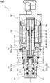
FIG. 2 is a sectional view showing a state where a main valve is opened and an auxiliary valve is closed in a non-energized state of the capacity control valve in the first embodiment. -
FIG. 3 is an enlarged sectional view ofFIG. 2 showing a sliding region formed between an outer peripheral surface of a main/auxiliary valve element and an inner peripheral surface of a valve housing in the non-energized state of the capacity control valve in the first embodiment. -
FIG. 4 is an enlarged sectional view showing the sliding region formed between the outer peripheral surface of the main/auxiliary valve element and the inner peripheral surface of the valve housing in an energized state of the capacity control valve in the first embodiment. -
FIG. 5 is an explanatory view showing a structure of a groove formed on the outer peripheral surface of the main/auxiliary valve element in the first embodiment. -
FIG. 6A is a view for explaining a state where a swirling current is generated in the groove by a fluid flowing from the high-pressure side to the low-pressure side in the sliding region in the energized state of the capacity control valve in the first embodiment; andFIG. 6B is a schematic view showing the swirling current flowing from the high-pressure side to the low-pressure side in the groove in the first embodiment. -
FIG. 7 is an enlarged sectional view showing a sliding region formed between an outer peripheral surface of a main/auxiliary valve element and an inner peripheral surface of a valve housing in an energized state of a capacity control valve according to a second embodiment of the present invention. -
FIG. 8 is an enlarged sectional view showing a sliding region formed between an outer peripheral surface of a main/auxiliary valve element and an inner peripheral surface of a valve housing in an energized state of a capacity control valve according to a third embodiment of the present invention. -
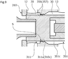
FIG. 9 is an enlarged sectional view showing a sliding region formed between an outer peripheral surface of a main/auxiliary valve element and an inner peripheral surface of a valve housing in an energized state of a capacity control valve according to a fourth embodiment of the present invention. - Modes for carrying out a capacity control valve according to the present invention will be described below based on embodiments.
- A capacity control valve according to a first embodiment of the present invention will be described with reference to
FIGS. 1 to 6 . Hereinafter, description will be given with the left and right sides seen from the front side ofFIG. 2 being the left and right sides of the capacity control valve. - A capacity control valve V of the present invention is assembled into a variable displacement compressor M used for an air conditioning system of an automobile, etc. By variably controlling pressure of a working fluid (hereinafter, simply referred to as the "fluid") serving as a coolant, a discharge amount of the variable displacement compressor M is controlled and the air conditioning system is adjusted to have a desired cooling ability.
- First of all, the variable displacement compressor M will be described. As shown in
FIG. 1 , the variable displacement compressor M has a casing 1 including a discharge chamber 2, asuction chamber 3, a control chamber 4, andplural cylinders 4a. A communication passage (not shown) providing direct communication between the control chamber 4 and thesuction chamber 3 is provided in the variable displacement compressor M. A fixed orifice for adjusting to balance pressure between thesuction chamber 3 and the control chamber 4 is provided in this communication passage. - The variable displacement compressor M also includes a rotating
shaft 5 to be driven and rotated by an engine (not shown) installed outside the casing 1, a swash plate 6 coupled to the rotatingshaft 5 in an eccentric state by a hinge mechanism 8 in the control chamber 4, and plural pistons 7 coupled to the swash plate 6 and fitted reciprocatably in therespective cylinders 4a. With using the capacity control valve V to be driven to open and close by electromagnetic force, a tilt angle of the swash plate 6 is continuously changed by appropriately controlling pressure in the control chamber 4 while utilizing suction pressure Ps of thesuction chamber 3 that suctions the fluid, discharge pressure Pd of the discharge chamber 2 that discharges the fluid pressurized by the pistons 7, and control pressure Pc of the control chamber 4 that houses the swash plate 6. Thereby, a stroke amount of the pistons 7 is changed to control a discharge amount of the fluid. For convenience of description, the capacity control valve V assembled into the variable displacement compressor M is not shown inFIG. 1 . - Specifically, the higher the control pressure Pc in the control chamber 4 is, the smaller the tilt angle of the swash plate 6 with respect to the rotating
shaft 5 becomes, and the more the stroke amount of the pistons 7 is reduced. However, when the pressure becomes fixed pressure or more, the swash plate 6 is brought into a substantially perpendicular state with respect to the rotatingshaft 5, that is, a state where the swash plate is slightly tilted from the exactly perpendicular state. At this time, the stroke amount of the pistons 7 becomes minimum, and pressurization of the fluid in thecylinders 4a by the pistons 7 becomes minimum. Therefore, the discharge amount of the fluid to the discharge chamber 2 is reduced, and the cooling ability of the air conditioning system becomes minimum. Meanwhile, the lower the control pressure Pc in the control chamber 4 is, the larger the tilt angle of the swash plate 6 with respect to the rotatingshaft 5 becomes, and the more the stroke amount of the pistons 7 is increased. However, when the pressure becomes fixed pressure or less, the tilt angle of the swash plate 6 with respect to the rotatingshaft 5 becomes maximum. At this time, the stroke amount of the pistons 7 becomes maximum, and the pressurization of the fluid in thecylinders 4a by the pistons 7 becomes maximum. Therefore, the discharge amount of the fluid to the discharge chamber 2 is increased, and the cooling ability of the air conditioning system becomes maximum. - As shown in
FIG. 2 , the capacity control valve V assembled into the variable displacement compressor M adjusts an electric current energized in acoil 86 forming asolenoid 80 and performs open/close control of amain valve 50 and anauxiliary valve 53 in the capacity control valve V, and also performs open/close control of a pressuresensitive valve 54 by suction pressure Ps in anintermediary communication passage 55, so that by controlling the fluid flowing into the control chamber 4 or flowing out from the control chamber 4, the control pressure Pc in the control chamber 4 is variably controlled. Theintermediary communication passage 55 passes through over the axial direction by connecting a main/auxiliary valve element 51 serving as a valve element and a hollow hole formed inside a pressuresensitive valve member 52, and forms a flow passage for discharging a liquid coolant. In detail, partly due to liquefication of the fluid whose pressure is increased in the control chamber 4 by leaving the variable displacement compressor M in a stop state for a long time, but by closing themain valve 50 and opening theauxiliary valve 53 by start-up of the variable displacement compressor M and energization of the capacity control valve V, and further by contracting a pressuresensitive body 61 and opening the pressuresensitive valve 54 by high suction pressure Ps in theintermediary communication passage 55, the liquid coolant of the control chamber 4 can be discharged to thesuction chamber 3 via theintermediary communication passage 55 for a short time. - In the present embodiment, the
main valve 50 is formed by the main/auxiliary valve element 51 and amain valve seat 10a serving as a valve seat which is formed in avalve housing 10, and by bringing and separating an axiallyleft end 51a of the main/auxiliary valve element 51 into contact with and from themain valve seat 10a, themain valve 50 is opened and closed. Theauxiliary valve 53 is formed by the main/auxiliary valve element 51 and anauxiliary valve seat 82a formed on the inner diameter side of an axially left end surface which serves as an opening end surface of a fixediron core 82, and by bringing and separating an axiallyright end 51b of the main/auxiliary valve element 51 into contact with and from theauxiliary valve seat 82a, theauxiliary valve 53 is opened and closed. The pressuresensitive valve 54 is formed by acap 70 forming the pressuresensitive body 61 and an annular pressuresensitive valve seat 52a formed in an axially left end of the pressuresensitive valve member 52. By bringing and separating a sealingsurface 70a formed on the outer diameter side of an axially right end of thecap 70 into contact with and from the pressuresensitive valve seat 52a, the pressuresensitive valve 54 is opened and closed. - Next, a structure of the capacity control valve V will be described. As shown in
FIG. 2 , the capacity control valve V is mainly formed by thevalve housing 10 made of a metal material or a resin material, the main/auxiliary valve element 51 arranged reciprocatably in the axial direction in thevalve housing 10, the pressuresensitive valve member 52, the pressuresensitive body 61 that applies axially rightward bias force to the main/auxiliary valve element 51 and the pressuresensitive valve member 52 in accordance with the suction pressure Ps in theintermediary communication passage 55, and thesolenoid 80 connected to thevalve housing 10, the solenoid that applies drive force to the main/auxiliary valve element 51 and the pressuresensitive valve member 52. - As shown in
FIG. 2 , thesolenoid 80 is mainly formed by acasing 81 having an openingportion 81a which is open on the axially left side, the substantially cylindrical fixediron core 82 inserted into theopening portion 81a of thecasing 81 from the axially left side and fixed on the inner diameter side of thecasing 81, adrive rod 83 inserted into the fixediron core 82 reciprocatably in the axial direction, the drive rod whose axially left end portion is inserted and fixed to the main/auxiliary valve element 51, amovable iron core 84 to which an axially right end portion of thedrive rod 83 is inserted and fixed, acoil spring 85 provided between the fixediron core 82 and themovable iron core 84, the coil spring biasing themovable iron core 84 to the axially right side which is the valve opening direction of themain valve 50, and theexcitation coil 86 wound on the outside of the fixediron core 82 via a bobbin. - A recessed
portion 81b in which the inner diameter side of an axially left end is recessed to the axially right side is formed in thecasing 81. An axially right end portion of thevalve housing 10 is inserted and fixed to this recessedportion 81b in a substantially sealed manner. - The fixed
iron core 82 is made of a rigid body which is a magnetic material such as iron or silicon steel, and includes acylindrical portion 82b extending in the axial direction, the cylindrical portion where aninsertion hole 82c into which thedrive rod 83 is inserted is formed, and anannular flange portion 82d extending in the outer diameter direction from an outer peripheral surface of an axially left end portion of thecylindrical portion 82b. Theauxiliary valve seat 82a is formed on the inner diameter side of the opening end surface of the fixediron core 82, that is, on an axially left end surface of thecylindrical portion 82b. - The fixed
iron core 82 is inserted and fixed to a recessedportion 10b recessed to the axially left side on the inner diameter side of an axially right end of thevalve housing 10 which is inserted and fixed to the recessedportion 81b of thecasing 81 in a substantially sealed manner in a state where an axially right end surface of theflange portion 82d is abutted with a bottom surface of the recessedportion 81b of thecasing 81. - Next, a structure of the
valve housing 10 will be described. As shown inFIG. 2 , aPd port 12 serving as a discharge port which communicates with the discharge chamber 2 of the variable displacement compressor M, aPs port 13 serving as a suction port which communicates with thesuction chamber 3 of the variable displacement compressor M, and aPc port 14 serving as a control port which communicates with the control chamber 4 of the variable displacement compressor M are formed in thevalve housing 10. - The
valve housing 10 is formed in a substantially cylindrical bottomed shape by press-fitting apartition adjusting member 71 to an axially left end portion in a substantially sealed manner. Thepartition adjusting member 71 can adjust the bias force of the pressuresensitive body 61 by adjusting an installment position of thevalve housing 10 in the axial direction. - A
first valve chamber 20 communicating with thePd port 12 where an axially left end portion of the main/auxiliary valve element 51 is arranged, asecond valve chamber 30 communicating with thePs port 13 where an axially right end portion of the main/auxiliary valve element 51 is arranged, and a pressuresensitive chamber 60 communicating with thePc port 14 where the pressuresensitive body 61 is arranged are formed inside thevalve housing 10. - As shown in
FIGS. 3 and4 , the main/auxiliary valve element 51 and the pressuresensitive valve member 52 connected to this main/auxiliary valve element 51 are arranged reciprocatably in the axial direction inside thevalve housing 10. An annular projectedportion 11 projecting in the inner diameter direction from a part between thePd port 12 and thePs port 13 in the axial direction is provided on an inner peripheral surface of thevalve housing 10, and a small-diameter guide hole 10c on which an outerperipheral surface 51c of the main/auxiliary valve element 51 is slidable is formed by an innerperipheral surface 11a of this projectedportion 11. The projectedportion 11 is formed to have a trapezoidal section by the innerperipheral surface 11a forming theguide hole 10c on which the outerperipheral surface 51c of the main/auxiliary valve element 51 is slidable and extending along the axial direction, aside surface 11b extending orthogonally to the axial direction on the side of thefirst valve chamber 20, and atapered side surface 11c whose diameter is gradually increased to the axially right side on the side of thesecond valve chamber 30. - In such a way, inside the
valve housing 10, thefirst valve chamber 20 and thesecond valve chamber 30 are partitioned in a sealed manner by the outerperipheral surface 51c of the main/auxiliary valve element 51 and the innerperipheral surface 11a of the projectedportion 11 forming theguide hole 10c, both the surfaces extending in parallel in the axial direction. A tiny clearance C (seeFIG. 6A ) is formed between the outerperipheral surface 51c of the main/auxiliary valve element 51 and the innerperipheral surface 11a of the projectedportion 11 forming theguide hole 10c by slightly separating the surfaces from each other in the radial direction. The main/auxiliary valve element 51 is smoothly relatively movable in the axial direction with respect to thevalve housing 10. - In the present embodiment, a part in which the inner
peripheral surface 11a of the projectedportion 11 forming theguide hole 10c and the outerperipheral surface 51c of the main/auxiliary valve element 51 slide with each other will be described as a sliding region S. Axial length L1 of the sliding region S corresponds to axial length of the innerperipheral surface 11a of the projectedportion 11 forming theguide hole 10c. The axial length L1 of the sliding region S in the present embodiment is set to be 0.3 mm, and radial length of the clearance C is set to be 10 µm. That is, the radial length of the clearance C is formed within a range from 1/10 to 1/300 of the axial length L1 of the sliding region S. The axial length L1 of the sliding region S is preferably within a range from 0.2 mm to 1.5 mm, and the radial length of the clearance C is preferably within a range from 5 µm to 20 µm. - As shown in
FIG. 4 , in an energized state of the capacity control valve V, the main/auxiliary valve element 51 is moved to the axially left side by the drive force of thesolenoid 80, the axiallyleft end 51a of the main/auxiliary valve element 51 is seated on themain valve seat 10a formed in thevalve housing 10, and themain valve 50 is closed, so that a flow of the fluid running from thefirst valve chamber 20 to the pressuresensitive chamber 60 is blocked (see a dotted arrow ofFIG. 4 ). Thus, a flow of the fluid running to the sliding region S is generated by a pressure difference (Pd > Ps) between the inside of thefirst valve chamber 20 to which the discharge pressure Pd is supplied form thePd port 12 and the inside of thesecond valve chamber 30 to which the suction pressure Ps is supplied from the Ps port 13 (see a solid arrow ofFIG. 4 ). As shown inFIG. 3 , in a non-energized state of the capacity control valve V, by separating the axiallyleft end 51a of the main/auxiliary valve element 51 from themain valve seat 10a formed in thevalve housing 10 and opening themain valve 50, thefirst valve chamber 20 communicates with the pressuresensitive chamber 60 to which the control pressure Pc is supplied from thePc port 14, and the fluid flows from thefirst valve chamber 20 to the pressuresensitive chamber 60 by a pressure difference (Pd > Pc) between the inside of thefirst valve chamber 20 and the inside of the pressure sensitive chamber 60 (see a solid arrow ofFIG. 3 ). Thus, the pressure difference between the inside of thefirst valve chamber 20 and the inside of thesecond valve chamber 30 is decreased, and the flow of the fluid running to the sliding region S is substantially not generated. - Next, a structure of the main/
auxiliary valve element 51 will be described. As shown inFIG. 2 , the main/auxiliary valve element 51 is formed in a cylindrical shape. The axially left end portion of thedrive rod 83 forming thesolenoid 80 is inserted and fixed to the axially right end portion of the main/auxiliary valve element 51 via anadapter 87, and the pressuresensitive valve member 52 of a separate body formed in a substantially cylindrical shape and a substantially artillery battery shape when seen from the side is inserted and fixed to the axially left end portion of the main/auxiliary valve element 51 in a substantially sealed manner. Both are movable in the axial direction. - As shown in
FIGS. 3 to 5 , agroove 56 is formed on the outerperipheral surface 51c of the main/auxiliary valve element 51. Thegroove 56 is formed by two threads ofspiral grooves peripheral surface 51c of the main/auxiliary valve element 51 for one and a half rolls while being tilted in the axial direction, the spiral grooves whose circumferential phases are displaced from each other by 180 degrees. That is, thegroove 56 is formed as a so-called two-thread spiral groove. Thespiral grooves peripheral surface 51c of the main/auxiliary valve element 51 for one and a half rolls but may be freely formed with the number of rolls of thespiral grooves groove 56 in an annular shape, the number is preferably one or more. Further, thegroove 56 is not limited to the groove formed as a two-thread spiral groove but thegroove 56 may be formed by three or more threads of spiral grooves as a so-called multiple-thread spiral groove. Regarding the main/auxiliary valve element 51 inFIGS. 2 to 4 , part of the outerperipheral surface 51c is shown in order to illustrate thegroove 56. For convenience of description, in the figures, one of the spiral grooves may be dotted in order to distinguish between the two threads of the spiral grooves. - As shown in
FIG. 5 in particular, groove sections of thespiral grooves spiral grooves spiral grooves - In the
spiral grooves groove inlets groove outlets peripheral surface 51c of the main/auxiliary valve element 51. In thespiral grooves roll portions groove inlets groove outlets FIG. 3 ) is also the same. As shown inFIG. 3 , the axial length L2 of the pitch for one roll of thespiral grooves - As shown in
FIGS. 3 and4 , in a stroke range of the main/auxiliary valve element 51, thegroove inlets spiral grooves groove outlets side surface 11c in the projectedportion 11 of thevalve housing 10, that is, in thesecond valve chamber 30 on the low-pressure side of the sliding region S. Thegroove outlets second valve chamber 30 but may be formed, for example, in such a manner that thegroove outlets second valve chamber 30 by a stroke of the main/auxiliary valve element 51 according to the capacity control valve V being controlled from the energized state into the non-energized state. - As described above, by forming the
groove 56 formed by the two threads of thespiral grooves peripheral surface 51c of the main/auxiliary valve element 51, as shown inFIG. 6A , by the fluid flowing from thefirst valve chamber 20 on the high-pressure side to thesecond valve chamber 30 on the low-pressure side in the sliding region S, a swirling current W along the groove sections of thespiral grooves peripheral surface 51c of the main/auxiliary valve element 51, and hence becomes a fluid resistance portion with respect to the fluid flowing in the axial direction from the high-pressure side to the low-pressure side in the sliding region S, so that an amount of the fluid leaked from the high-pressure side to the low-pressure side of the sliding region S can be reduced. Therefore, by shortening the axial length L1 of the sliding region S and enlarging the clearance C of the sliding region S, by the swirling current W, while reducing the amount of the fluid leaked to the low-pressure side of the sliding region S, it is possible to suppress contaminant, etc. from remaining and accumulating in the sliding region S to enhance resistance to foreign substances. Since the swirling current W is generated by optimizing the axial length L1 of the sliding region S and the clearance C of the sliding region S, it is possible to reduce the amount of the fluid leaked to the low-pressure side of the sliding region S. Since part of the swirling current W formed in thespiral grooves spiral grooves - As shown in
FIG. 6B , the swirling current W flowing from thegroove inlets spiral grooves groove outlets spiral grooves spiral grooves spiral grooves peripheral surface 51c of the main/auxiliary valve element 51. - The clearance C of the sliding region S is formed to extend in parallel to the axial direction by the outer
peripheral surface 51c of the main/auxiliary valve element 51 extending in parallel in the axial direction and the innerperipheral surface 11a of the projectedportion 11 forming theguide hole 10c. Thus, in the sliding region S, it is possible to more easily generate the swirling current W in thespiral grooves - On the outer
peripheral surface 51c of the main/auxiliary valve element 51 in the sliding region S, by forming thespiral grooves roll portions spiral grooves spiral grooves - As shown in
FIGS. 3 and4 , in the stroke range of the main/auxiliary valve element 51, thegroove inlets spiral grooves groove outlets second valve chamber 30 on the low-pressure side of the sliding region S. Thus, contaminant, etc. pulled into thespiral grooves second valve chamber 30. Not all contaminant, etc. pulled into thespiral grooves groove outlets second valve chamber 30. However, as shown inFIG. 6A , for example, in theroll portion 57c of thespiral groove 57 positioned out of the sliding region S and exposed in thesecond valve chamber 30, the force of the swirling current W is weakened. Thus, part of contaminant, etc. pulled into thespiral grooves roll portions second valve chamber 30. - By forming the
groove 56 by the two threads of thespiral grooves plural spiral grooves spiral grooves plural groove inlets plural groove outlets groove 56 and the swirling current W is easily generated. Since contaminant, etc. can be dispersed over theplural spiral grooves spiral grooves groove 56 is the two-thread spiral groove formed by the two threads of thespiral grooves spiral grooves - The
groove inlets spiral grooves first valve chamber 20 on the high-pressure side of the sliding region S. Thus, thefirst valve chamber 20 and thesecond valve chamber 30 do not directly communicate with each other by thespiral grooves second valve chamber 30 on the low-pressure side of the sliding region S is reduced. The axial length L2 of the pitch for one roll of thespiral grooves groove 56 is longer than the axial length L1 of the sliding region S. Thus, in a state where thegroove inlets groove outlets roll portions second valve chamber 30 on the low-pressure side of the sliding region S. In thespiral grooves roll portions second valve chamber 30 on the low-pressure side of the sliding region S by a short distance of one roll from thegroove inlets spiral grooves - Since the
groove 56 is formed on the outerperipheral surface 51c of the main/auxiliary valve element 51, processing for forming thegroove 56 is easily performed. - The plural spiral grooves forming the
groove 56 are not limited to the spiral grooves formed by the same configurations but spiral grooves having different sectional shapes, width, depth, extension size, etc. may be combined. - By forming width of the
groove outlets spiral grooves groove inlets spiral grooves groove outlets second valve chamber 30. - Next, a capacity control valve according to a second embodiment of the present invention will be described with reference to
FIG. 7 . The same constituent parts as the constituent parts shown in the first embodiment will be given the same reference signs and duplicated description will be omitted. - A capacity control valve V in the second embodiment will be described. As shown in
FIG. 7 , in the second embodiment, agroove 156 is formed on an outerperipheral surface 151c of a main/auxiliary valve element 151 serving as a valve element. Thegroove 156 is formed by one thread of aspiral groove 157 extending on the outerperipheral surface 151c of the main/auxiliary valve element 151 for one and a half rolls while being tilted in the axial direction as a so-called single-thread spiral groove. According to this, thegroove 156 is formed as the single-thread spiral groove on the outerperipheral surface 151c of the main/auxiliary valve element 151. Thus, processing for forming thegroove 156 is easily performed. - Next, a capacity control valve according to a third embodiment of the present invention will be described with reference to
FIG. 8 . The same constituent parts as the constituent parts shown in the first embodiment will be given the same reference signs and duplicated description will be omitted. - A capacity control valve V in the third embodiment will be described. As shown in
FIG. 8 , in the third embodiment, agroove 256 is formed on an outerperipheral surface 251c of a main/auxiliary valve element 251 serving as a valve element. Thegroove 256 is formed by an endlessannular groove 257 extending on the outerperipheral surface 251c of the main/auxiliary valve element 251 for one roll. According to this, a fluid less easily flows along the extending direction of thegroove 256, and it is possible to reduce an amount of the fluid leaked to asecond valve chamber 30 from a sliding region S. In a non-energized state of the capacity control valve V, at the time of moving the main/auxiliary valve element 251 to the axially right side, by forming in such a manner that at least part of theannular groove 257 is exposed in thesecond valve chamber 30 on the low-pressure side of the sliding region S, contaminant, etc. pulled in theannular groove 257 by a swirling current W (seeFIG. 6 ) may be more easily discharged to thesecond valve chamber 30. - The plural
annular grooves 257 forming thegroove 256 may be provided in the axial direction. - Next, a capacity control valve according to a fourth embodiment of the present invention will be described with reference to
FIG. 9 . The same constituent parts as the constituent parts shown in the first embodiment will be given the same reference signs and duplicated description will be omitted. - A capacity control valve V in the fourth embodiment will be described. As shown in
FIG. 9 , in the fourth embodiment, an outerperipheral surface 351c of a main/auxiliary valve element 351 serving as a valve element is formed in a flat curved surface, and no grooves are provided on this curved surface. - As shown in
FIG. 9 , an annular projectedportion 311 projecting in the inner diameter direction from a part between aPd port 12 and aPs port 13 in the axial direction is provided on an inner peripheral surface of avalve housing 310, and a small-diameter guide hole 310c on which the outerperipheral surface 351c of the main/auxiliary valve element 351 is slidable is formed by an innerperipheral surface 311a of this projectedportion 311. Agroove 356 is formed on the innerperipheral surface 311a of the projectedportion 311. Thegroove 356 is formed by one thread of aspiral groove 357 extending on the innerperipheral surface 311a of the projectedportion 311 for one and a half rolls while being tilted in the axial direction as a so-called single-thread spiral groove. Thegroove 356 formed on the innerperipheral surface 311a of the projectedportion 311 is not limited to the groove formed by a single-thread spiral groove but may be formed by a multiple-thread spiral groove such as two threads of spiral grooves as in the first embodiment, or an endless annular groove as in the third embodiment. - The embodiments of the present invention are described above with the drawings. However, specific configurations are not limited to these embodiments but the present invention includes changes and additions within the range not departing from the scope of the present invention.
- For example, in the above embodiments, the
auxiliary valve 53 is not necessarily provided. An axially right end of the main/auxiliary valve element is only required to function as a support member that receives a load in the axial direction and a sealing function is not necessarily required. - The example in which the main/auxiliary valve element and the pressure
sensitive valve member 52 are formed as separate bodies is described. However, both may be integrated. The example in which thedrive rod 83 and the main/auxiliary valve element are formed as separate bodies is described. However, both may be integrated. Further, the main/auxiliary valve element, the pressuresensitive valve member 52, and thedrive rod 83 may be integrated. - The communication passage providing direct communication between the control chamber 4 and the
suction chamber 3 of the variable displacement compressor M and the fixed orifice are not necessarily provided. - The groove may be formed by combining spiral grooves as in the first embodiment or the second embodiment and an annular groove as in the third embodiment. Grooves may be formed on both the outer peripheral surface of the main/auxiliary valve element and the inner peripheral surface of the valve housing.
- The projected portion provided on the inner peripheral surface of the valve housing may not have the tapered side surface but may be formed to have a rectangular section.
- The main/auxiliary valve element is not limited to the main/auxiliary valve element formed to have the same diameter over the axial direction but may be a main/auxiliary valve element whose diameter is partly reduced but not in a range where the groove is formed. In this case, the axial length of the sliding region may be shorter than the axial length of the inner peripheral surface of the projected portion forming the guide hole of the valve housing.
- In the present invention, the valve element has functions of reciprocating in the axial direction by the drive force of the solenoid, sliding with the guide hole of the valve housing, and being brought into contact with or separated from the main valve seat. In the first to fourth embodiments, the main/auxiliary valve element is described as an example. However, for example, as long as the drive rod in the first to fourth embodiments slides with the guide hole of the valve housing, the drive rod forms the valve element together with the main/auxiliary valve element.
-
- 1
- Casing
- 2
- Discharge chamber
- 3
- Suction chamber
- 4
- Control chamber
- 10
- Valve housing
- 10a
- Main valve seat (valve seat)
- 10c
- Guide hole
- 11
- Projected portion
- 11a
- Inner peripheral surface
- 12
- Pd port (discharge port)
- 13
- Ps port (suction port)
- 14
- Pc port (control port)
- 20
- First valve chamber
- 30
- Second valve chamber
- 50
- Main valve
- 51
- Main/auxiliary valve element (valve element)
- 51c
- Outer peripheral surface
- 56
- Groove
- 57, 58
- Spiral groove
- 57a, 58a
- Groove inlet
- 57b, 58b
- Groove outlet
- 57c, 58c
- Roll portion
- 60
- Pressure sensitive chamber
- 61
- Pressure sensitive body
- 80
- Solenoid
- 151
- Main/auxiliary valve element (valve element)
- 151c
- Outer peripheral surface
- 156
- Groove
- 157
- Spiral groove
- 251
- Main/auxiliary valve element (valve element)
- 251c
- Outer peripheral surface
- 256
- Groove
- 257
- Annular groove
- 310
- Valve housing
- 310c
- Guide hole
- 311
- Projected portion
- 311a
- Inner peripheral surface
- 351
- Main/auxiliary valve element (valve element)
- 351c
- Outer peripheral surface
- 356
- Groove
- 357
- Spiral groove
- C
- Clearance
- S
- Sliding region
- V
- Capacity control valve
- W
- Swirling current
- X
- Axial flow
Claims (7)
- A capacity control valve comprising:a valve housing provided with a discharge port through which a discharge fluid of discharge pressure passes, a suction port through which a suction fluid of suction pressure passes, and a control port through which a control fluid of control pressure passes; anda valve element configured to be brought into contact with and separated from a valve seat by a driving force of a solenoid to open and close a communication between the control port and the discharge port or a communication between the control port and the suction port, whereina sliding region is formed by an inner peripheral surface of the valve housing and an outer peripheral surface of the valve element,a groove extending in a circumferential direction is formed in at least one of the inner peripheral surface of the valve housing and the outer peripheral surface of the valve element, andthe sliding region has a structure in which a swirling current is generated in the groove by a fluid flowing from a high-pressure side to a low-pressure side in a clearance between the inner peripheral surface of the valve housing and the outer peripheral surface of the valve element.
- The capacity control valve according to claim 1, wherein
a radial length of the clearance is within a range from 1/10 to 1/300 of an axial length of the sliding region. - The capacity control valve according to claim 2, wherein
the radial length of the clearance is within a range from 5 µm to 20 µm. - The capacity control valve according to claim 2 or 3, wherein
a depth of the groove is larger than the radial length of the clearance. - The capacity control valve according to any one of claims 1 to 3, wherein
the groove is exposed on the low-pressure side of the sliding region in a stroke range of the valve element. - The capacity control valve according to claim 5, wherein
the groove extends so as to form a spiral shape, and a pitch of the groove for one roll from a groove inlet is longer than the axial length of the sliding region. - The capacity control valve according to any one of claims 1 to 6, wherein
the groove is a multiple-thread spiral groove.
Applications Claiming Priority (2)
| Application Number | Priority Date | Filing Date | Title |
|---|---|---|---|
| JP2019037960 | 2019-03-01 | ||
| PCT/JP2020/007953 WO2020179597A1 (en) | 2019-03-01 | 2020-02-27 | Capacity control valve |
Publications (3)
| Publication Number | Publication Date |
|---|---|
| EP3933197A1 true EP3933197A1 (en) | 2022-01-05 |
| EP3933197A4 EP3933197A4 (en) | 2022-11-30 |
| EP3933197B1 EP3933197B1 (en) | 2024-10-09 |
Family
ID=72337053
Family Applications (1)
| Application Number | Title | Priority Date | Filing Date |
|---|---|---|---|
| EP20765478.1A Active EP3933197B1 (en) | 2019-03-01 | 2020-02-27 | Capacity control valve |
Country Status (5)
| Country | Link |
|---|---|
| US (1) | US11598437B2 (en) |
| EP (1) | EP3933197B1 (en) |
| JP (1) | JP7391486B2 (en) |
| CN (1) | CN113474554B (en) |
| WO (1) | WO2020179597A1 (en) |
Families Citing this family (2)
| Publication number | Priority date | Publication date | Assignee | Title |
|---|---|---|---|---|
| US12292130B2 (en) * | 2019-01-21 | 2025-05-06 | Eagle Industry Co., Ltd. | Capacity control valve |
| JP7302514B2 (en) * | 2020-03-23 | 2023-07-04 | 株式会社デンソー | solenoid valve |
Family Cites Families (62)
| Publication number | Priority date | Publication date | Assignee | Title |
|---|---|---|---|---|
| JPS5862775A (en) | 1981-10-08 | 1983-04-14 | Sankyo Seiki Mfg Co Ltd | Processor for card with magnetic stripe |
| JP3089816B2 (en) | 1992-04-28 | 2000-09-18 | 株式会社豊田自動織機製作所 | Swash plate type variable displacement compressor |
| JPH06200875A (en) | 1993-01-08 | 1994-07-19 | Toyota Autom Loom Works Ltd | Rocking swash plate type variable displacement compressor |
| JP3242496B2 (en) | 1993-07-06 | 2001-12-25 | 株式会社豊田自動織機 | External switching type displacement control valve for variable displacement compressor |
| JPH09144929A (en) | 1995-11-16 | 1997-06-03 | Tosok Corp | Solenoid valve |
| US6010312A (en) | 1996-07-31 | 2000-01-04 | Kabushiki Kaisha Toyoda Jidoshokki Seiksakusho | Control valve unit with independently operable valve mechanisms for variable displacement compressor |
| JP3583951B2 (en) | 1999-06-07 | 2004-11-04 | 株式会社豊田自動織機 | Capacity control valve |
| JP2001073939A (en) | 1999-08-31 | 2001-03-21 | Toyota Autom Loom Works Ltd | Control valve for variable displacement compressor and variable displacement compressor |
| JP2001099060A (en) | 1999-10-04 | 2001-04-10 | Fuji Koki Corp | Control valve for variable displacement compressor |
| JP2001132632A (en) | 1999-11-10 | 2001-05-18 | Toyota Autom Loom Works Ltd | Control valve of variable displacement compressor |
| JP3942851B2 (en) | 2001-07-31 | 2007-07-11 | 株式会社テージーケー | Capacity control valve |
| JP4242624B2 (en) | 2002-09-26 | 2009-03-25 | イーグル工業株式会社 | Capacity control valve and control method thereof |
| JP4316955B2 (en) | 2003-08-11 | 2009-08-19 | イーグル工業株式会社 | Capacity control valve |
| JP2006097665A (en) | 2004-06-28 | 2006-04-13 | Toyota Industries Corp | Capacity control valve in variable displacement compressor |
| JP4431462B2 (en) | 2004-08-10 | 2010-03-17 | 株式会社鷺宮製作所 | Swash plate type variable capacity compressor and electromagnetic control valve |
| CN100516516C (en) | 2005-02-24 | 2009-07-22 | 株式会社丰田自动织机 | Capacity control valve |
| JP2006307828A (en) | 2005-03-31 | 2006-11-09 | Tgk Co Ltd | Control valve for variable displacement compressor |
| US7895527B2 (en) | 2005-07-15 | 2011-02-22 | Siemens Medical Solutions Usa, Inc. | Systems, user interfaces, and methods for processing medical data |
| CN101410620B (en) | 2006-03-15 | 2011-03-23 | 伊格尔工业股份有限公司 | Capacity control valve |
| JP2007247512A (en) | 2006-03-15 | 2007-09-27 | Toyota Industries Corp | Capacity control valve in variable capacity type compressor |
| JP2008014269A (en) | 2006-07-07 | 2008-01-24 | Toyota Industries Corp | Displacement control valve for variable displacement compressor |
| JP2008202572A (en) | 2007-02-22 | 2008-09-04 | Toyota Industries Corp | Capacity control valve of variable displacement compressor |
| JP4861956B2 (en) | 2007-10-24 | 2012-01-25 | 株式会社豊田自動織機 | Capacity control valve in variable capacity compressor |
| JP2011032916A (en) | 2009-07-31 | 2011-02-17 | Tgk Co Ltd | Control valve |
| KR101099121B1 (en) | 2009-08-19 | 2011-12-27 | 주식회사 두원전자 | Vacuum bellows assembly manufacturing method |
| KR101319565B1 (en) | 2010-03-16 | 2013-10-23 | 이구루코교 가부시기가이샤 | Volume control valve |
| US8757988B2 (en) | 2010-04-29 | 2014-06-24 | Eagle Industry Co., Ltd. | Capacity control valve |
| JP5907432B2 (en) * | 2011-06-15 | 2016-04-26 | イーグル工業株式会社 | Capacity control valve |
| JP5665722B2 (en) | 2011-11-17 | 2015-02-04 | 株式会社豊田自動織機 | Capacity control valve |
| KR101322404B1 (en) | 2012-01-19 | 2013-10-28 | (주)대정고분자산업 | Electric control valve for variable displacement compressor |
| US20150068628A1 (en) | 2012-05-24 | 2015-03-12 | Eagle Industry Co., Ltd. | Capacity control valve |
| JP6064132B2 (en) | 2012-10-09 | 2017-01-25 | 株式会社テージーケー | Compound valve |
| US9714646B2 (en) | 2012-12-12 | 2017-07-25 | Eagle Industry Co., Ltd. | Capacity control valve |
| JP6020130B2 (en) | 2012-12-19 | 2016-11-02 | 株式会社豊田自動織機 | Variable capacity swash plate compressor |
| EP2952741B1 (en) | 2013-01-31 | 2019-03-13 | Eagle Industry Co., Ltd. | Variable capacity compressor |
| JP6103586B2 (en) | 2013-03-27 | 2017-03-29 | 株式会社テージーケー | Control valve for variable capacity compressor |
| JP6149239B2 (en) | 2013-06-28 | 2017-06-21 | 株式会社テージーケー | Control valve for variable capacity compressor |
| JP6206274B2 (en) | 2014-03-19 | 2017-10-04 | 株式会社豊田自動織機 | Capacity control valve |
| EP3239570B1 (en) | 2014-12-25 | 2020-05-13 | Eagle Industry Co., Ltd. | Volume control valve |
| JP6500183B2 (en) | 2015-04-02 | 2019-04-17 | 株式会社テージーケー | Control valve for variable displacement compressor |
| US20170028462A1 (en) | 2015-07-28 | 2017-02-02 | Primetals Technologies USA LLC | Simple copper tube design for continuous casting process with enhanced rigidity |
| WO2017057160A1 (en) | 2015-09-29 | 2017-04-06 | 株式会社ヴァレオジャパン | Variable displacement compressor control valve |
| JP6383720B2 (en) | 2015-12-16 | 2018-08-29 | 株式会社不二工機 | Control valve for variable displacement compressor |
| JP6663227B2 (en) | 2016-01-19 | 2020-03-11 | サンデン・オートモーティブコンポーネント株式会社 | Displacement control valve for variable displacement compressor |
| JP6500186B2 (en) | 2016-02-25 | 2019-04-17 | 株式会社テージーケー | Control valve for variable displacement compressor |
| WO2017159553A1 (en) | 2016-03-17 | 2017-09-21 | イーグル工業株式会社 | Capacity control valve |
| CN108071824B (en) | 2016-06-13 | 2021-08-10 | 株式会社Tgk | Control valve for variable displacement compressor |
| JP6714274B2 (en) | 2016-06-13 | 2020-06-24 | 株式会社テージーケー | Control valve for variable capacity compressor |
| JP2018021646A (en) | 2016-08-05 | 2018-02-08 | 株式会社鷺宮製作所 | Pressure sensitive control valve |
| JP2018040385A (en) | 2016-09-05 | 2018-03-15 | 株式会社テージーケー | solenoid valve |
| EP3564528B1 (en) | 2016-12-28 | 2022-08-03 | Eagle Industry Co., Ltd. | Capacity control valve |
| JP2018145877A (en) | 2017-03-06 | 2018-09-20 | 株式会社豊田自動織機 | Variable capacity-type swash plate compressor |
| JP6924476B2 (en) | 2017-04-07 | 2021-08-25 | 株式会社テージーケー | Control valve for variable displacement compressor |
| JP6997536B2 (en) | 2017-05-09 | 2022-01-17 | サンデン・オートモーティブコンポーネント株式会社 | Solenoid control valve and variable displacement compressor equipped with it |
| JP2019002384A (en) | 2017-06-19 | 2019-01-10 | サンデン・オートモーティブコンポーネント株式会社 | Variable displacement compressor |
| CN110770441B (en) | 2017-07-05 | 2021-12-14 | 伊格尔工业股份有限公司 | volume control valve |
| US11512786B2 (en) | 2017-11-30 | 2022-11-29 | Eagle Industry Co., Ltd. | Capacity control valve and control method for capacity control valve |
| JP7167067B2 (en) | 2018-01-26 | 2022-11-08 | イーグル工業株式会社 | capacity control valve |
| EP3760864B1 (en) | 2018-02-27 | 2022-11-16 | Eagle Industry Co., Ltd. | Capacity control valve |
| US11873805B2 (en) | 2018-08-08 | 2024-01-16 | Eagle Industry Co., Ltd. | Capacity control valve |
| US11053933B2 (en) | 2018-12-13 | 2021-07-06 | Eagle Industry Co., Ltd. | Displacement control valve |
| US11300219B2 (en) | 2020-07-28 | 2022-04-12 | Mahle International Gmbh | Variable-capacity compressor control valve |
-
2020
- 2020-02-27 WO PCT/JP2020/007953 patent/WO2020179597A1/en not_active Ceased
- 2020-02-27 US US17/433,558 patent/US11598437B2/en active Active
- 2020-02-27 JP JP2021504011A patent/JP7391486B2/en active Active
- 2020-02-27 EP EP20765478.1A patent/EP3933197B1/en active Active
- 2020-02-27 CN CN202080016397.7A patent/CN113474554B/en active Active
Also Published As
| Publication number | Publication date |
|---|---|
| WO2020179597A1 (en) | 2020-09-10 |
| CN113474554B (en) | 2023-04-14 |
| US11598437B2 (en) | 2023-03-07 |
| CN113474554A (en) | 2021-10-01 |
| EP3933197B1 (en) | 2024-10-09 |
| US20220154837A1 (en) | 2022-05-19 |
| JPWO2020179597A1 (en) | 2020-09-10 |
| JP7391486B2 (en) | 2023-12-05 |
| EP3933197A4 (en) | 2022-11-30 |
Similar Documents
| Publication | Publication Date | Title |
|---|---|---|
| EP3239570B1 (en) | Volume control valve | |
| EP3822485B1 (en) | Capacity control valve | |
| EP3835578B1 (en) | Capacity control valve | |
| JPWO2019107377A1 (en) | Capacity control valve and capacity control valve control method | |
| JP7504989B2 (en) | Capacity Control Valve | |
| CN112384695B (en) | capacity control valve | |
| EP4160016B1 (en) | Capacity control valve | |
| CN111051753A (en) | The electromagnetic valve | |
| EP3951172B1 (en) | Capacity control valve | |
| EP3933197B1 (en) | Capacity control valve | |
| EP3835577B1 (en) | Capacity control valve | |
| EP4242504A2 (en) | Capacity control valve | |
| KR20210091270A (en) | capacity control valve | |
| EP4219994A1 (en) | Valve | |
| EP4194726A1 (en) | Valve | |
| CN113646529A (en) | volume control valve |
Legal Events
| Date | Code | Title | Description |
|---|---|---|---|
| STAA | Information on the status of an ep patent application or granted ep patent |
Free format text: STATUS: THE INTERNATIONAL PUBLICATION HAS BEEN MADE |
|
| PUAI | Public reference made under article 153(3) epc to a published international application that has entered the european phase |
Free format text: ORIGINAL CODE: 0009012 |
|
| STAA | Information on the status of an ep patent application or granted ep patent |
Free format text: STATUS: REQUEST FOR EXAMINATION WAS MADE |
|
| 17P | Request for examination filed |
Effective date: 20210906 |
|
| AK | Designated contracting states |
Kind code of ref document: A1 Designated state(s): AL AT BE BG CH CY CZ DE DK EE ES FI FR GB GR HR HU IE IS IT LI LT LU LV MC MK MT NL NO PL PT RO RS SE SI SK SM TR |
|
| DAV | Request for validation of the european patent (deleted) | ||
| DAX | Request for extension of the european patent (deleted) | ||
| A4 | Supplementary search report drawn up and despatched |
Effective date: 20221103 |
|
| RIC1 | Information provided on ipc code assigned before grant |
Ipc: F16K 41/00 20060101ALI20221027BHEP Ipc: F04B 27/18 20060101AFI20221027BHEP |
|
| RIC1 | Information provided on ipc code assigned before grant |
Ipc: F16K 47/06 20060101ALI20240424BHEP Ipc: F16K 31/06 20060101ALI20240424BHEP Ipc: F04B 27/18 20060101AFI20240424BHEP |
|
| GRAP | Despatch of communication of intention to grant a patent |
Free format text: ORIGINAL CODE: EPIDOSNIGR1 |
|
| STAA | Information on the status of an ep patent application or granted ep patent |
Free format text: STATUS: GRANT OF PATENT IS INTENDED |
|
| INTG | Intention to grant announced |
Effective date: 20240603 |
|
| GRAS | Grant fee paid |
Free format text: ORIGINAL CODE: EPIDOSNIGR3 |
|
| GRAA | (expected) grant |
Free format text: ORIGINAL CODE: 0009210 |
|
| STAA | Information on the status of an ep patent application or granted ep patent |
Free format text: STATUS: THE PATENT HAS BEEN GRANTED |
|
| AK | Designated contracting states |
Kind code of ref document: B1 Designated state(s): AL AT BE BG CH CY CZ DE DK EE ES FI FR GB GR HR HU IE IS IT LI LT LU LV MC MK MT NL NO PL PT RO RS SE SI SK SM TR |
|
| REG | Reference to a national code |
Ref country code: CH Ref legal event code: EP |
|
| REG | Reference to a national code |
Ref country code: DE Ref legal event code: R096 Ref document number: 602020039152 Country of ref document: DE |
|
| REG | Reference to a national code |
Ref country code: IE Ref legal event code: FG4D |
|
| REG | Reference to a national code |
Ref country code: LT Ref legal event code: MG9D |
|
| REG | Reference to a national code |
Ref country code: NL Ref legal event code: MP Effective date: 20241009 |
|
| REG | Reference to a national code |
Ref country code: AT Ref legal event code: MK05 Ref document number: 1730852 Country of ref document: AT Kind code of ref document: T Effective date: 20241009 |
|
| PG25 | Lapsed in a contracting state [announced via postgrant information from national office to epo] |
Ref country code: NL Free format text: LAPSE BECAUSE OF FAILURE TO SUBMIT A TRANSLATION OF THE DESCRIPTION OR TO PAY THE FEE WITHIN THE PRESCRIBED TIME-LIMIT Effective date: 20241009 |
|
| PG25 | Lapsed in a contracting state [announced via postgrant information from national office to epo] |
Ref country code: NL Free format text: LAPSE BECAUSE OF FAILURE TO SUBMIT A TRANSLATION OF THE DESCRIPTION OR TO PAY THE FEE WITHIN THE PRESCRIBED TIME-LIMIT Effective date: 20241009 |
|
| PG25 | Lapsed in a contracting state [announced via postgrant information from national office to epo] |
Ref country code: IS Free format text: LAPSE BECAUSE OF FAILURE TO SUBMIT A TRANSLATION OF THE DESCRIPTION OR TO PAY THE FEE WITHIN THE PRESCRIBED TIME-LIMIT Effective date: 20250209 Ref country code: PT Free format text: LAPSE BECAUSE OF FAILURE TO SUBMIT A TRANSLATION OF THE DESCRIPTION OR TO PAY THE FEE WITHIN THE PRESCRIBED TIME-LIMIT Effective date: 20250210 Ref country code: HR Free format text: LAPSE BECAUSE OF FAILURE TO SUBMIT A TRANSLATION OF THE DESCRIPTION OR TO PAY THE FEE WITHIN THE PRESCRIBED TIME-LIMIT Effective date: 20241009 |
|
| PG25 | Lapsed in a contracting state [announced via postgrant information from national office to epo] |
Ref country code: FI Free format text: LAPSE BECAUSE OF FAILURE TO SUBMIT A TRANSLATION OF THE DESCRIPTION OR TO PAY THE FEE WITHIN THE PRESCRIBED TIME-LIMIT Effective date: 20241009 |
|
| PG25 | Lapsed in a contracting state [announced via postgrant information from national office to epo] |
Ref country code: BG Free format text: LAPSE BECAUSE OF FAILURE TO SUBMIT A TRANSLATION OF THE DESCRIPTION OR TO PAY THE FEE WITHIN THE PRESCRIBED TIME-LIMIT Effective date: 20241009 |
|
| PG25 | Lapsed in a contracting state [announced via postgrant information from national office to epo] |
Ref country code: ES Free format text: LAPSE BECAUSE OF FAILURE TO SUBMIT A TRANSLATION OF THE DESCRIPTION OR TO PAY THE FEE WITHIN THE PRESCRIBED TIME-LIMIT Effective date: 20241009 |
|
| PG25 | Lapsed in a contracting state [announced via postgrant information from national office to epo] |
Ref country code: NO Free format text: LAPSE BECAUSE OF FAILURE TO SUBMIT A TRANSLATION OF THE DESCRIPTION OR TO PAY THE FEE WITHIN THE PRESCRIBED TIME-LIMIT Effective date: 20250109 |
|
| PG25 | Lapsed in a contracting state [announced via postgrant information from national office to epo] |
Ref country code: LV Free format text: LAPSE BECAUSE OF FAILURE TO SUBMIT A TRANSLATION OF THE DESCRIPTION OR TO PAY THE FEE WITHIN THE PRESCRIBED TIME-LIMIT Effective date: 20241009 Ref country code: GR Free format text: LAPSE BECAUSE OF FAILURE TO SUBMIT A TRANSLATION OF THE DESCRIPTION OR TO PAY THE FEE WITHIN THE PRESCRIBED TIME-LIMIT Effective date: 20250110 Ref country code: AT Free format text: LAPSE BECAUSE OF FAILURE TO SUBMIT A TRANSLATION OF THE DESCRIPTION OR TO PAY THE FEE WITHIN THE PRESCRIBED TIME-LIMIT Effective date: 20241009 |
|
| PG25 | Lapsed in a contracting state [announced via postgrant information from national office to epo] |
Ref country code: PL Free format text: LAPSE BECAUSE OF FAILURE TO SUBMIT A TRANSLATION OF THE DESCRIPTION OR TO PAY THE FEE WITHIN THE PRESCRIBED TIME-LIMIT Effective date: 20241009 |
|
| PG25 | Lapsed in a contracting state [announced via postgrant information from national office to epo] |
Ref country code: RS Free format text: LAPSE BECAUSE OF FAILURE TO SUBMIT A TRANSLATION OF THE DESCRIPTION OR TO PAY THE FEE WITHIN THE PRESCRIBED TIME-LIMIT Effective date: 20250109 |
|
| PG25 | Lapsed in a contracting state [announced via postgrant information from national office to epo] |
Ref country code: SM Free format text: LAPSE BECAUSE OF FAILURE TO SUBMIT A TRANSLATION OF THE DESCRIPTION OR TO PAY THE FEE WITHIN THE PRESCRIBED TIME-LIMIT Effective date: 20241009 |
|
| PG25 | Lapsed in a contracting state [announced via postgrant information from national office to epo] |
Ref country code: DK Free format text: LAPSE BECAUSE OF FAILURE TO SUBMIT A TRANSLATION OF THE DESCRIPTION OR TO PAY THE FEE WITHIN THE PRESCRIBED TIME-LIMIT Effective date: 20241009 |
|
| REG | Reference to a national code |
Ref country code: DE Ref legal event code: R097 Ref document number: 602020039152 Country of ref document: DE |
|
| PG25 | Lapsed in a contracting state [announced via postgrant information from national office to epo] |
Ref country code: EE Free format text: LAPSE BECAUSE OF FAILURE TO SUBMIT A TRANSLATION OF THE DESCRIPTION OR TO PAY THE FEE WITHIN THE PRESCRIBED TIME-LIMIT Effective date: 20241009 |
|
| PG25 | Lapsed in a contracting state [announced via postgrant information from national office to epo] |
Ref country code: RO Free format text: LAPSE BECAUSE OF FAILURE TO SUBMIT A TRANSLATION OF THE DESCRIPTION OR TO PAY THE FEE WITHIN THE PRESCRIBED TIME-LIMIT Effective date: 20241009 |
|
| PG25 | Lapsed in a contracting state [announced via postgrant information from national office to epo] |
Ref country code: SK Free format text: LAPSE BECAUSE OF FAILURE TO SUBMIT A TRANSLATION OF THE DESCRIPTION OR TO PAY THE FEE WITHIN THE PRESCRIBED TIME-LIMIT Effective date: 20241009 |
|
| PG25 | Lapsed in a contracting state [announced via postgrant information from national office to epo] |
Ref country code: CZ Free format text: LAPSE BECAUSE OF FAILURE TO SUBMIT A TRANSLATION OF THE DESCRIPTION OR TO PAY THE FEE WITHIN THE PRESCRIBED TIME-LIMIT Effective date: 20241009 |
|
| PG25 | Lapsed in a contracting state [announced via postgrant information from national office to epo] |
Ref country code: IT Free format text: LAPSE BECAUSE OF FAILURE TO SUBMIT A TRANSLATION OF THE DESCRIPTION OR TO PAY THE FEE WITHIN THE PRESCRIBED TIME-LIMIT Effective date: 20241009 |
|
| PLBE | No opposition filed within time limit |
Free format text: ORIGINAL CODE: 0009261 |
|
| STAA | Information on the status of an ep patent application or granted ep patent |
Free format text: STATUS: NO OPPOSITION FILED WITHIN TIME LIMIT |
|
| PG25 | Lapsed in a contracting state [announced via postgrant information from national office to epo] |
Ref country code: SE Free format text: LAPSE BECAUSE OF FAILURE TO SUBMIT A TRANSLATION OF THE DESCRIPTION OR TO PAY THE FEE WITHIN THE PRESCRIBED TIME-LIMIT Effective date: 20241009 |
|
| PG25 | Lapsed in a contracting state [announced via postgrant information from national office to epo] |
Ref country code: MC Free format text: LAPSE BECAUSE OF FAILURE TO SUBMIT A TRANSLATION OF THE DESCRIPTION OR TO PAY THE FEE WITHIN THE PRESCRIBED TIME-LIMIT Effective date: 20241009 |
|
| 26N | No opposition filed |
Effective date: 20250710 |
|
| REG | Reference to a national code |
Ref country code: CH Ref legal event code: PL |
|
| PG25 | Lapsed in a contracting state [announced via postgrant information from national office to epo] |
Ref country code: LU Free format text: LAPSE BECAUSE OF NON-PAYMENT OF DUE FEES Effective date: 20250227 |
|
| PG25 | Lapsed in a contracting state [announced via postgrant information from national office to epo] |
Ref country code: CH Free format text: LAPSE BECAUSE OF NON-PAYMENT OF DUE FEES Effective date: 20250228 |
|
| GBPC | Gb: european patent ceased through non-payment of renewal fee |
Effective date: 20250227 |
|
| REG | Reference to a national code |
Ref country code: BE Ref legal event code: MM Effective date: 20250228 |
|
| PG25 | Lapsed in a contracting state [announced via postgrant information from national office to epo] |
Ref country code: GB Free format text: LAPSE BECAUSE OF NON-PAYMENT OF DUE FEES Effective date: 20250227 |
|
| PG25 | Lapsed in a contracting state [announced via postgrant information from national office to epo] |
Ref country code: FR Free format text: LAPSE BECAUSE OF NON-PAYMENT OF DUE FEES Effective date: 20250228 |
|
| PG25 | Lapsed in a contracting state [announced via postgrant information from national office to epo] |
Ref country code: BE Free format text: LAPSE BECAUSE OF NON-PAYMENT OF DUE FEES Effective date: 20250228 |
|
| PG25 | Lapsed in a contracting state [announced via postgrant information from national office to epo] |
Ref country code: IE Free format text: LAPSE BECAUSE OF NON-PAYMENT OF DUE FEES Effective date: 20250227 |
|
| PGFP | Annual fee paid to national office [announced via postgrant information from national office to epo] |
Ref country code: DE Payment date: 20260102 Year of fee payment: 7 |