EP3933122A1 - Working machine - Google Patents
Working machine Download PDFInfo
- Publication number
- EP3933122A1 EP3933122A1 EP20766596.9A EP20766596A EP3933122A1 EP 3933122 A1 EP3933122 A1 EP 3933122A1 EP 20766596 A EP20766596 A EP 20766596A EP 3933122 A1 EP3933122 A1 EP 3933122A1
- Authority
- EP
- European Patent Office
- Prior art keywords
- work
- gnss
- upper swing
- controller
- swing structure
- Prior art date
- Legal status (The legal status is an assumption and is not a legal conclusion. Google has not performed a legal analysis and makes no representation as to the accuracy of the status listed.)
- Granted
Links
Images








Classifications
-
- E—FIXED CONSTRUCTIONS
- E02—HYDRAULIC ENGINEERING; FOUNDATIONS; SOIL SHIFTING
- E02F—DREDGING; SOIL-SHIFTING
- E02F9/00—Component parts of dredgers or soil-shifting machines, not restricted to one of the kinds covered by groups E02F3/00 - E02F7/00
- E02F9/26—Indicating devices
-
- E—FIXED CONSTRUCTIONS
- E02—HYDRAULIC ENGINEERING; FOUNDATIONS; SOIL SHIFTING
- E02F—DREDGING; SOIL-SHIFTING
- E02F9/00—Component parts of dredgers or soil-shifting machines, not restricted to one of the kinds covered by groups E02F3/00 - E02F7/00
- E02F9/26—Indicating devices
- E02F9/261—Surveying the work-site to be treated
-
- E—FIXED CONSTRUCTIONS
- E02—HYDRAULIC ENGINEERING; FOUNDATIONS; SOIL SHIFTING
- E02F—DREDGING; SOIL-SHIFTING
- E02F9/00—Component parts of dredgers or soil-shifting machines, not restricted to one of the kinds covered by groups E02F3/00 - E02F7/00
- E02F9/20—Drives; Control devices
- E02F9/2004—Control mechanisms, e.g. control levers
-
- E—FIXED CONSTRUCTIONS
- E02—HYDRAULIC ENGINEERING; FOUNDATIONS; SOIL SHIFTING
- E02F—DREDGING; SOIL-SHIFTING
- E02F9/00—Component parts of dredgers or soil-shifting machines, not restricted to one of the kinds covered by groups E02F3/00 - E02F7/00
- E02F9/08—Superstructures; Supports for superstructures
- E02F9/0858—Arrangement of component parts installed on superstructures not otherwise provided for, e.g. electric components, fenders, air-conditioning units
-
- E—FIXED CONSTRUCTIONS
- E02—HYDRAULIC ENGINEERING; FOUNDATIONS; SOIL SHIFTING
- E02F—DREDGING; SOIL-SHIFTING
- E02F9/00—Component parts of dredgers or soil-shifting machines, not restricted to one of the kinds covered by groups E02F3/00 - E02F7/00
- E02F9/20—Drives; Control devices
- E02F9/2025—Particular purposes of control systems not otherwise provided for
- E02F9/205—Remotely operated machines, e.g. unmanned vehicles
-
- E—FIXED CONSTRUCTIONS
- E02—HYDRAULIC ENGINEERING; FOUNDATIONS; SOIL SHIFTING
- E02F—DREDGING; SOIL-SHIFTING
- E02F9/00—Component parts of dredgers or soil-shifting machines, not restricted to one of the kinds covered by groups E02F3/00 - E02F7/00
- E02F9/26—Indicating devices
- E02F9/264—Sensors and their calibration for indicating the position of the work tool
- E02F9/265—Sensors and their calibration for indicating the position of the work tool with follow-up actions (e.g. control signals sent to actuate the work tool)
-
- G—PHYSICS
- G01—MEASURING; TESTING
- G01S—RADIO DIRECTION-FINDING; RADIO NAVIGATION; DETERMINING DISTANCE OR VELOCITY BY USE OF RADIO WAVES; LOCATING OR PRESENCE-DETECTING BY USE OF THE REFLECTION OR RERADIATION OF RADIO WAVES; ANALOGOUS ARRANGEMENTS USING OTHER WAVES
- G01S19/00—Satellite radio beacon positioning systems; Determining position, velocity or attitude using signals transmitted by such systems
- G01S19/01—Satellite radio beacon positioning systems transmitting time-stamped messages, e.g. GPS [Global Positioning System], GLONASS [Global Orbiting Navigation Satellite System] or GALILEO
- G01S19/13—Receivers
- G01S19/24—Acquisition or tracking or demodulation of signals transmitted by the system
- G01S19/28—Satellite selection
-
- G—PHYSICS
- G01—MEASURING; TESTING
- G01S—RADIO DIRECTION-FINDING; RADIO NAVIGATION; DETERMINING DISTANCE OR VELOCITY BY USE OF RADIO WAVES; LOCATING OR PRESENCE-DETECTING BY USE OF THE REFLECTION OR RERADIATION OF RADIO WAVES; ANALOGOUS ARRANGEMENTS USING OTHER WAVES
- G01S19/00—Satellite radio beacon positioning systems; Determining position, velocity or attitude using signals transmitted by such systems
- G01S19/38—Determining a navigation solution using signals transmitted by a satellite radio beacon positioning system
- G01S19/39—Determining a navigation solution using signals transmitted by a satellite radio beacon positioning system the satellite radio beacon positioning system transmitting time-stamped messages, e.g. GPS [Global Positioning System], GLONASS [Global Orbiting Navigation Satellite System] or GALILEO
- G01S19/42—Determining position
- G01S19/43—Determining position using carrier phase measurements, e.g. kinematic positioning; using long or short baseline interferometry
-
- G—PHYSICS
- G01—MEASURING; TESTING
- G01S—RADIO DIRECTION-FINDING; RADIO NAVIGATION; DETERMINING DISTANCE OR VELOCITY BY USE OF RADIO WAVES; LOCATING OR PRESENCE-DETECTING BY USE OF THE REFLECTION OR RERADIATION OF RADIO WAVES; ANALOGOUS ARRANGEMENTS USING OTHER WAVES
- G01S19/00—Satellite radio beacon positioning systems; Determining position, velocity or attitude using signals transmitted by such systems
- G01S19/38—Determining a navigation solution using signals transmitted by a satellite radio beacon positioning system
- G01S19/39—Determining a navigation solution using signals transmitted by a satellite radio beacon positioning system the satellite radio beacon positioning system transmitting time-stamped messages, e.g. GPS [Global Positioning System], GLONASS [Global Orbiting Navigation Satellite System] or GALILEO
- G01S19/53—Determining attitude
- G01S19/54—Determining attitude using carrier phase measurements; using long or short baseline interferometry
-
- E—FIXED CONSTRUCTIONS
- E02—HYDRAULIC ENGINEERING; FOUNDATIONS; SOIL SHIFTING
- E02F—DREDGING; SOIL-SHIFTING
- E02F9/00—Component parts of dredgers or soil-shifting machines, not restricted to one of the kinds covered by groups E02F3/00 - E02F7/00
- E02F9/20—Drives; Control devices
- E02F9/2058—Electric or electro-mechanical or mechanical control devices of vehicle sub-units
- E02F9/2079—Control of mechanical transmission
-
- E—FIXED CONSTRUCTIONS
- E02—HYDRAULIC ENGINEERING; FOUNDATIONS; SOIL SHIFTING
- E02F—DREDGING; SOIL-SHIFTING
- E02F9/00—Component parts of dredgers or soil-shifting machines, not restricted to one of the kinds covered by groups E02F3/00 - E02F7/00
- E02F9/20—Drives; Control devices
- E02F9/2058—Electric or electro-mechanical or mechanical control devices of vehicle sub-units
- E02F9/2087—Control of vehicle steering
-
- G—PHYSICS
- G01—MEASURING; TESTING
- G01S—RADIO DIRECTION-FINDING; RADIO NAVIGATION; DETERMINING DISTANCE OR VELOCITY BY USE OF RADIO WAVES; LOCATING OR PRESENCE-DETECTING BY USE OF THE REFLECTION OR RERADIATION OF RADIO WAVES; ANALOGOUS ARRANGEMENTS USING OTHER WAVES
- G01S19/00—Satellite radio beacon positioning systems; Determining position, velocity or attitude using signals transmitted by such systems
- G01S19/01—Satellite radio beacon positioning systems transmitting time-stamped messages, e.g. GPS [Global Positioning System], GLONASS [Global Orbiting Navigation Satellite System] or GALILEO
- G01S19/03—Cooperating elements; Interaction or communication between different cooperating elements or between cooperating elements and receivers
- G01S19/04—Cooperating elements; Interaction or communication between different cooperating elements or between cooperating elements and receivers providing carrier phase data
Definitions
- the present invention relates to a work machine such as a hydraulic excavator, and particularly to a work machine that incorporates a position measurement system that uses satellite signals of satellites to measure an absolute position of a monitor point set to a work device in a three-dimensional space.
- a predetermined point such as a predetermined point (monitor point) set to a work machine, using a three-dimensional position measurement system such as a GNSS (Global Navigation Satellite System) and to perform work management.
- GNSS Global Navigation Satellite System
- a typical example of the monitor point is a point set to a work device provided on a work machine, for example, a bucket distal end of a hydraulic excavator. If the position of the bucket distal end can be measured, by comparing measurement data by the measurement with terrain data or target shape data set in advance, a work progress situation during construction can be grasped, and accordingly, this enables management and control during construction. Further, by creating finished form data (for example, excavation terrain data) from a history of measurement data till the end of construction, construction management can be performed also after the construction.
- finished form data for example, excavation terrain data
- a work device that can be positioned higher than a GNSS antenna such as a boom, an arm, and a bucket or an obstacle around the work device becomes an obstacle to a signal (GNSS signal, satellite signal) transmitted from a GNSS satellite. Therefore, there is the possibility that the GNSS antenna may receive a GNSS signal as a diffracted wave or a reflected wave called multipath. If a diffracted wave or a reflected wave is used in position measurement of a monitor point, the possibility that a position measurement result may include an error is high.
- a solution method for eliminating the influence of the multipath for example, a solution method disclosed in Patent Document 1 is available.
- Patent Document 1 discloses a positioning apparatus that includes a reception device receiving signals from a plurality of transmitters (a plurality of satellites) and that decides transmitter positions of the individual transmitters (the plurality of satellites). Then, the positioning apparatus calculates transmitters (a plurality of satellites) from which signals can be received directly on the basis of the positions of the transmitters, a position of the positioning apparatus decided in a preceding operation cycle, and multipath information, and decides the present position of the positioning apparatus, ignoring the transmitters from which signals cannot be received directly.
- a reception device receiving signals from a plurality of transmitters (a plurality of satellites) and that decides transmitter positions of the individual transmitters (the plurality of satellites). Then, the positioning apparatus calculates transmitters (a plurality of satellites) from which signals can be received directly on the basis of the positions of the transmitters, a position of the positioning apparatus decided in a preceding operation cycle, and multipath information, and decides the present position of the positioning apparatus, ignoring the transmitters from which signals cannot be
- Patent Document 1 JP-2010-534849-T
- Patent Document 1 it is possible to reduce the influence of diffraction and reflection by an obstacle.
- a work machine that repeats a series of operations such as excavation, swing, and dumping of loaded soil like a hydraulic excavator
- the relative positions of the work machine and an obstacle around the work machine can change readily according to a change in posture of the work device or an upper swing structure. Therefore, there is the possibility that the combination of satellite signals to be used for position measurement may constantly switch.
- the position measurement by the GNSS has a subject that, if satellites to be used for position measurement switch, the position measurement error increases.
- the present invention has been made to solve the subject described above, and it is an object of the present invention to provide a work machine that can prevent accuracy degradation in GNSS position measurement even if the posture of a work device or an upper swing structure changes during work of the work machine.
- a work machine that includes a lower track structure, an upper swing structure swingably provided on the lower track structure and configuring a machine body together with the lower track structure, a work device rotatably provided on the upper swing structure, an inclination measurement device provided on the machine body, an angle measurement device provided on the work device, a three-dimensional position measurement device that calculates a three-dimensional position and a direction of itself on the basis of satellite signals of satellites, and a controller that calculates, on the basis of information from the inclination measurement device, the angle measurement device, and the three-dimensional position measurement device, a three-dimensional position and a posture of the machine body, and a three-dimensional position of a predetermined position of the work device, in which the three-dimensional position measurement device receives satellite signals of satellites, selects, from among the satellites whose satellite signals are received, the satellites to be used for calculation of a three-dimensional position and a direction of the three-dimensional position measurement device, and
- the controller stores, when the instruction is inputted through the storage instruction device, the combination of the satellites selected by the three-dimensional position measurement device as satellite selection information, and transmits, when a predetermined changing condition is satisfied, the satellite selection information to the three-dimensional measurement device, and the three-dimensional position measurement device preferentially selects, when the three-dimensional position measurement device receives the satellite selection information from the controller, the satellites included in the satellite selection information from among the satellites from which the satellite signals are received.
- the work accuracy can be improved.
- the present embodiment is an embodiment when the present invention is applied to a crawler type hydraulic excavator as a construction machine and a monitor point (control point) is set to a bucket distal end of the hydraulic excavator.
- a monitor point control point
- equivalent members are denoted by the same reference numerals and overlapping description is suitably omitted.
- FIG. 1 is a view depicting an appearance of the hydraulic excavator of the present embodiment.
- the hydraulic excavator 1 includes a lower track structure 2 that travels by crawlers driven by traveling hydraulic motors (not depicted), an upper swing structure 3 attached for swinging motion on the lower track structure 2 and configuring a machine body together with the lower track structure 2, a cab 4 provided on the upper swing structure 3, and a front work implement (work device) 5 attached to the upper swing structure 3.
- the upper swing structure 3 is driven to swing leftward and rightward by a swing hydraulic motor (not depicted).
- the front work implement 5 is an articulated type work apparatus including a boom 6 rotatably provided in upward and downward directions on the upper swing structure 3, an arm 7 rotatably provided in the upward and downward directions at a distal end of the boom 6, and a bucket (attachment) 8 rotatably provided in the upward and downward directions at a distal end of the arm 7.
- the boom 6, the arm 7, and the bucket 8 are driven by elongating or contracting a boom cylinder 9, an arm cylinder 10, and a bucket cylinder 11, respectively.
- Each of the boom 6, the arm 7, and the bucket 8 is sometimes referred to as a front member.
- a machine body IMU 21 for detecting an inclination angle (pitch angle) of the upper swing structure 3 with respect to a predetermined plane (for example, a horizontal plane) is attached to the upper swing structure 3.
- a boom IMU 22 for detecting an angle of the boom 6 (boom angle) with respect a predetermine plane (for example, the horizontal plane) is attached to the boom 6.
- An arm IMU 23 for detecting an angle of the arm 7 (arm angle) with respect to a predetermined plane (for example, the horizontal plane) is attached to the arm 7.
- a bucket IMU 24 for detecting an angle of the bucket 8 (bucket angle) with respect to a predetermined plane (for example, the horizontal plane) is attached to the bucket 8.
- the boom IMU 22, the arm IMU 23, and the bucket IMU 24 are sometimes referred to collectively as front IMUs (refer to FIG. 2 ).
- two GNSS antennae 31 and 32 for receiving satellite signals (navigation signals) transmitted from a plurality of GNSS satellites and an RTK correction data receiving antenna 34 for receiving RTK correction data (hereinafter described) from a reference station are provided.
- the two GNSS antennae 31 and 32 are installed on the left and right of a rear portion of the swing structure displaced from the center of swing of the upper swing structure 3.
- FIG. 2 is a block diagram of a position measurement system incorporated in the hydraulic excavator 1.
- the position measurement system 200 depicted in FIG. 2 includes a wireless device 35, a GNSS receiver 33, a controller 38, a display device 39 and a setting switch 40.
- the wireless device 35 receives RTK correction data (hereinafter described) from a reference station through the RTK correction data receiving antenna 34 and outputs the RTK correction data to the GNSS receiver 33.
- RTK correction data hereinafter described
- the GNSS receiver 33 calculates the position of the GNSS antenna 31 that is one of the two GNSS antennae 31 and 32 and a vector from the GNSS antenna 31 that is one of the two GNSS antennae 31 and 32 to the other GNSS antenna 32 on the real time basis on the basis of RTK correction data inputted from the wireless device 35 and signals from GNSS satellites received by the GNSS antennae 31 and 32. Accordingly, the position and the azimuth angle of the upper swing structure 3 in a geographic coordinate system (global coordinate system) can be calculated.
- the controller 38 receives the position and vector data calculated by the GNSS receiver 33 and angle data from the IMUs 21 to 24 as inputs thereto and calculates a position and an azimuth angle of the upper swing structure 3 and a position of the distal end (monitor point) of the bucket 8.
- the controller 38 includes, as hardware, an arithmetic processing unit (for example, a CPU), a storage device (for example, a semiconductor memory such as a ROM and a RAM), and an interface (inputting/outputting device).
- a program (software) stored in advance in the storage device is executed by the arithmetic processing unit, and arithmetic processing is performed by the arithmetic processing unit on the basis of data prescribed in the program and data inputted from the interface. Then, a signal (calculation result) is outputted from the interface to the outside.
- the GNSS receiver 33 can also include hardware similar to that of the controller 38.
- the display device (monitor) 39 displays a calculation result of the controller 38 and various kinds of data acquired by utilizing the calculation result.
- the setting switch (masking range reset switch) 40 is connected to the controller 38.
- the setting switch 40 is a switch for cancelling (deleting) all mask ranges (hereinafter described) set at that time.
- the setting switch 40 is depressed at a timing desired by an operator, and as a result, the controller 38 deletes all mask ranges. Details of setting of a mask range and a scene in which the setting switch 40 is utilized are hereinafter described.
- an external recording medium (external storage device) 42 such as a semiconductor memory can be connected to the controller 38.
- the external recording medium 42 has stored therein terrain data including present terrain data and target terrain data (also referred to as design data).
- the operator connects the external recording medium 42 to the controller 38 at a predetermined timing such as at the time of system startup and downloads, when necessary, data into a storage device in the controller 38. Then, at the time of end of a work or the like, for example, present terrain data after the work created from locus data on the bucket distal end position while the system is operating is recorded into the external recording medium 42 and is used in work management.
- FIG. 3 is a block diagram of an office side measurement system (reference station system) 50 having a role as a GNSS reference station.
- the office side measurement system 50 includes a GNSS antenna 52, a GNSS receiver 51, a wireless device 53, and a wireless antenna 54.
- the GNSS antenna 52 is an antenna for receiving satellite signals (navigation signals) transmitted from a plurality of GNSS satellites.
- the GNSS receiver 51 functions as a GNSS reference station (in the following description, the GNSS receiver 51 is sometimes represented as a GNSS reference station 51), and generates, on the basis of data on a three-dimensional position measured in advance (for example, the position of the GNSS antenna 52) and satellite signals received by the GNSS antenna 52, correction data for allowing the GNSS receiver 33 of the hydraulic excavator 1 to perform RTK (real time kinematic) measurement, and outputs the correction data to the wireless device 53.
- RTK real time kinematic
- the wireless device 53 transmits the correction data inputted from the GNSS receiver 51 to the wireless device 35 of the hydraulic excavator 1 through the wireless antenna 54.
- RTK measurement is performed by the GNSS receiver 33 depicted in FIG. 2 .
- the GNSS reference station 51 that creates correction data depicted in FIG. 3 is first required.
- the GNSS reference station 51 creates correction data for RTK measurement on the basis of the position data on the GNSS antenna 52 three-dimensionally measured in advance as described hereinabove and satellite signals from a plurality of GNSS satellites received by the GNSS antenna 52, and transmits the created correction data by the wireless device 53 in a fixed cycle through the antenna 54.
- the GNSS receiver 33 on the hydraulic excavator 1 side depicted in FIG. 2 performs RTK measurement on the three-dimensional position of the GNSS antenna 31 and the vector from the GNSS antenna 31 to the GNSS antenna 32 on the basis of the correction data received from the wireless device 35 through the antenna 34 and satellite signals from a plurality of GNSS satellites received by the GNSS antennae 31 and 32. Due to this RTK measurement, the three-dimensional position of the GNSS antenna 31 in the geographic coordinate system and the vector from the GNSS antenna 31 to the GNSS antenna 32 are measured with high accuracy. Then, the measured three-dimensional position data and vector data are inputted to the controller 38.
- the inclination angle of the hydraulic excavator 1 (upper swing structure 3) (namely, a pitch angle and a roll angle) and the angles of the boom 6, the arm 7, and the bucket 8 are measured by the IMUs 21 to 24 and are similarly inputted to the controller 38.
- the controller 38 performs general vector calculation and coordinate transformation on the basis of the various kinds of inputted data to calculate a position and a posture (including an azimuth angle) of the upper swing structure 3 and the position of the distal end (monitor point) of the bucket 8 in a predetermined coordinate system (for example, a site coordinate system set to the ground of the work site).
- a predetermined coordinate system for example, a site coordinate system set to the ground of the work site.
- the controller 38 to display an image of the bucket and a target terrain on the screen of the display device 39 on the basis of the calculated position and posture of the upper swing structure 3 and the calculated position of the distal end of the bucket 8, and the target terrain data inputted from the external recording medium 41 to notify the operator of the work situation.
- FIG. 4 schematically depicts a posture of the hydraulic excavator 1 upon excavation operation.
- the hydraulic excavator 1 performs a generally-called slope face forming work.
- the image depicted in FIG. 4 is generally equivalent to information displayed on the display device 39, and the operator will perform an excavation operation of the hydraulic excavator 1 on the basis of this information such that a present terrain 61 approaches a target terrain 62.
- FIG. 5 schematically depicts a posture of the hydraulic excavator 1 upon swing operation.
- the swing operation is performed in a state in which the boom 6 is raised after excavation operation ends, the arm 7 and the bucket 8 are moved inward, and a clearance between the bucket 8 and the ground is secured. Then, the arm 7 and the bucket 8 are dumped at a soil-dumping position to release the excavated soil down to a predetermined position. Thereafter, swing operation for returning to the excavation position is performed, and the excavation operation is repeated.
- FIG. 6 schematically depicts an excavation position and a soil-dumping position of the hydraulic excavator 1 and arrangement of GNSS satellites 81 to 87 existing within a sky view of the GNSS antennae 31 and 32 at that time.
- a state in which the front work implement 5 is directed to the upper side is defined as an excavation position 71
- a state in which the front work implement 5 is directed to the left side is defined as a soil-dumping position 72.
- movement from the excavation position 71 to the soil-dumping position 72 is performed by left swing and movement from the soil-dumping position 72 to the excavation position 71 is performed by right swing.
- the GNSS receiver 33 performs various condition decisions regarding the quality of satellite signals from GNSS satellites received by the GNSS antennae 31 and 32, arrangement of the GNSS satellites from which satellite signals are received, and so forth to select GNSS satellites (satellite signals) to be used in position calculation.
- the arrangement of GNSS satellites is evaluated with a numerical value called DOP (Dilution of Precision), and, for example, in such a case that GNSS satellites are distributed so as to be clustered to one direction of the sky view, the DOP is bad (the numerical value is high). As a result, the position accuracy in calculation is deteriorated. In contrast, where GNSS satellites are distributed without being clustered to the one direction in the sky view, the DOP is good (the numerical value is low), and the position accuracy in calculation is improved. This arises from that position measurement by the GNSS is a measurement system that applies triangulation.
- DOP Deution of Precision
- the GNSS satellites 81 to 87 which can be caught are arranged in such arrangement as indicated in FIG. 6 , as GNSS satellites to be used for position calculation at the excavation position 71, for example, the satellites 81, 83, 84, and 86 indicated with hatched lines in FIG. 7 are selected.
- the GNSS satellites 82 to 85 indicated with hatched lines in FIG. 8 are selected, and the GNSS satellites sometimes change from those of the combination selected at the excavation position 71 in FIG. 7 .
- the hydraulic excavator 1 returns to the excavation position 71 by right swing and repeats the excavation operation.
- the hydraulic excavator 1 swings rightward from the soil-dumping position 72 to the excavation position 71, since the satellite signals of the GNSS satellites 82 to 85 are not blocked by the front work implement 5, the combination of GNSS satellites to be used for position calculation is kept to be the GNSS satellites 82 to 85 also at the excavation position 71 as depicted in FIG. 9 . Consequently, the change from the combination of the GNSS satellites 81, 83, 84, and 86 having been selected at the time of the excavation operation in the preceding operation cycle sometimes remains.
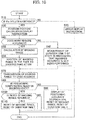
- FIG. 10 is a flow chart depicting an example of the satellite selection logic to be executed by the controller 38. It is to be noted that the flow chart of FIG. 10 is calculated repeatedly in a fixed cycle (for example, 100 ms).
- the controller 38 decides whether a Fix solution is obtained by RTK based on information from the GNSS receiver 33. Whether or not this state is achieved can be decided by referring to, for example, a GGA sentence of an NMEA message from the GNSS receiver 33.
- step S10 When it is decided at step S10 that a Fix solution is not obtained, the controller 38 decides that correct position measurement has not been performed, and the processing advances to step S20 at which the controller 38 displays on the display device 39 that correct measurement is not performed and returns to an initial state (waits till a next control cycle). On the other hand, when it is decided at step S10 that a Fix solution is obtained, the processing advances to step S30.
- the controller 38 performs, on the basis of a three-dimensional position of the GNSS antenna 31 inputted from the GNSS receiver 33, vector information from the GNSS antenna 31 to the GNSS antenna 32, and angle information inputted from the IMUs 21 to 24, general vector calculation and coordinate transformation to calculate the position and the posture of the upper swing structure 3 and the position of the distal end of the bucket 8 in the site coordinate system. Then, the controller 38 displays posture information of the bucket 8, a present terrain generated on the basis of terrain data acquired from the external recording medium 42 and information of a target shape on the display device 39.
- step S40 the controller 38 decides by a decision method depicted in FIG. 11 whether or not the hydraulic excavator 1 is performing a work that requires accuracy.
- the logic (decision logic) of the controller 38 for deciding whether or not the hydraulic excavator 1 is performing an excavation work that requires accuracy at step S40 is described with reference to FIG. 11.
- FIG. 11 is a flow chart depicting one of particular examples of the process performed at step S40.
- the controller 38 decides whether or not the distance between the front work implement 5 and a target surface (target surface distance) is equal to or smaller than a predetermined value d1.
- target surface distance for example, the distance between the bucket distal end (claw tip) position and the target surface can be used.
- a perpendicular line is drawn from the position of the bucket distal end (monitor point) calculated at step S30, a point at which the perpendicular line crosses with the target terrain surface defined by the target terrain data is calculated, and the distance between the point and the bucket distal end can be determined as the target surface distance.
- the controller 38 decides that, because the bucket distal end is at a position spaced away from the target surface, an excavation work that requires accuracy is not being performed. On the other hand, when it is the decision that the target surface distance is equal to or smaller than the predetermined value d1, the processing advances to step S402.
- the controller 38 decides whether or not an excavation operation is inputted to an operation device (not depicted) for operating the front work implement 5 (the boom 6, the arm 7, and the bucket 8) installed in the cab 4. Whether or not an excavation operation is inputted is decided here depending upon whether or not the arm 7 (arm cylinder 10) is being driven. Whether or not the arm 7 (arm cylinder 10) is being driven can be decided, for example, by detecting the operation pilot pressure of the arm 7 outputted from the operation device by a pressure sensor and checking whether or not the detected pressure exceeds a predetermined value.
- the controller 38 deems that the hydraulic excavator 1 is performing an excavation work that requires accuracy. In this manner, even if the distance between the bucket distal end and the target surface is equal to or smaller than the predetermined value d1 at step S401, when it is decided at step S402 that an excavation operation is not being performed, for example, in such a state in which the arm 7 stops with the distal end of the bucket 8 contacting with the terrain excavated according to the target surface, a decision that an excavation work is not being performed is made. Therefore, a mask range hereinafter described can be prevented from being widened more than necessary.
- step S401 when it is decided at step S401 that the target surface distance exceeds the predetermined value d1, for example, also when a rough finish work is being performed, the mask range hereinafter described can be prevented from being widened more than necessary.
- decision of an excavation operation may be made additionally on the basis of the operation pilot pressure of the boom 6 or the bucket 8. Further, the decision may be made taking not only an instantaneous value but also continuity of the operation pilot pressure in the past (namely, a time series of the detected operation pilot pressure), and the like into consideration.
- step S401 the operation pilot pressure
- step S402 an excavation reactive force or the like acting upon the arm cylinder 10
- step S402 the decision may be made on one of these two processes (steps S401 and S402). In other words, the decision may be made based on at least one of the two processes.
- step S40 when it is decided at step S40 that the hydraulic excavator 1 is not performing a work that requires accuracy, the processing advances to step S45.
- step S45 the controller 38 starts measurement of a time period (duration) T during which the state in which it is decided that the hydraulic excavator 1 is not performing a work that requires accuracy continues, and then, the processing advances to step S70. It is to be noted that, when measurement of the time period T is already started at the time of reaching step S45, the measurement is assumed to be continued.
- step S40 when it is decided at step S40 that the hydraulic excavator 1 is performing a work that requires accuracy, the processing advances to step S50.
- the controller 38 sets a range within which, when each of the two GNSS antennae 31 and 32 receives satellite signals from a plurality of GNSS satellites, the front work implement 5 possibly becomes an obstacle to the satellite signals, as a mask range in a coordinate system (for example, a site coordinate system) set to the ground.
- a satellite signal from a GNSS satellite positioned within the mask range can be excluded from the satellite signals to be utilized for position measurement by the GNSS receiver 33.
- a range of satellite arrangement that is not to be used for position measurement is calculated at step S50.
- the controller 38 of the present embodiment sets a mask range at step S50 on the basis of the installation positions of the two GNSS antennae 31 and 32 on the upper swing structure 3 (hydraulic excavator 1) (for example, coordinate positions in the machine body coordinate system set to the upper swing structure 3) stored in the storage device of the controller 38 in advance, a movable range of the front work implement 5 (boom 6, arm 7, and bucket 8), an inclination angle of the upper swing structure 3 detected by the machine body IMU 21, and an azimuth angle of the upper swing structure 3 calculated from the vector information from the GNSS antenna 31 to the GNSS antenna 32.
- the mask range is set for each of the two GNSS antennae 31 and 32.
- the mask range can be defined by a combination of an azimuth angle range (angle range in the leftward and rightward direction) and an elevation angle range (angle range in the upward and downward direction) with reference to each of the GNSS antennae 31 and 32.
- the controller 38 can set also a range within which satellite signals can be blocked by the obstacles as a mask range in addition to the setting of the mask range arising from the front work implement 5 described above.
- a mask range may be set in the following manner.
- Present terrain data from the external recording medium 42 is stored in advance as shape data on obstacles in the storage device in the controller 38.
- the controller 38 calculates, on the basis of the position, azimuth angle and inclination angle of the upper swing structure 3 in the geographic coordinate system (global coordinate system), installation positions of the two GNSS antennae 31 and 32 on the upper swing structure 3 (hydraulic excavator 1) and the present terrain data, a cross sectional shape of the present terrain in a predetermined azimuth angle direction with reference to the azimuth angle of the upper swing structure 3. Then, the controller 38 further takes into consideration a range within which the present terrain that has the cross sectional shape when each of the two GNSS antennae 31 and 32 receives satellite signals from a plurality of GNSS satellites may become an obstacle to the satellite signals, to thereby set the mask range.
- a mask range for the GNSS antenna 31 is described for the convenience of description, a mask range for the GNSS antenna 32 can also be calculated by a similar method.
- the elevation angle mask angle that defines an elevation angle range of a mask range a direction from the horizontal plane to the sky is defined as a positive direction, and the zenith direction is defined as an elevation angle of 90 degrees. Therefore, as the elevation angle mask angle, the lower end is 0 degrees, and the upper end is 90 degrees in the maximum. Further, the azimuth angle mask angle that defines an azimuth angle range of a mask range is defined as a range from 0 degrees to 360 degrees with the north direction defined as 0 degrees and the clockwise direction defined as a positive direction.
- FIG. 12 is a view depicting an example of a relation between the machine body reference azimuth angle and the front screening elevation angle ⁇ ft, and a front screening elevation angle ⁇ ft is set for each machine body reference azimuth angle.
- a range equal to or smaller than the front screening elevation angle ⁇ ft becomes a range (mask range) within which a satellite signal is blocked.
- the machine body reference azimuth angle and the front screening elevation angle ⁇ ft here are defined in the machine body coordinate system set to the upper swing structure 3. If, as depicted in FIG. 13 , using the GNSS antenna 31 as a reference, the forward direction of the hydraulic excavator 1 is defined as machine body reference azimuth angle of 0 degrees and the clockwise direction is a positive direction, the front screening elevation angle ⁇ ft is defined at intervals of 5 degrees while the machine body reference azimuth angle reaches 360 degrees from 0 degrees. In the example of FIG. 12 , since the front work implement 5 does not become an obstacle to satellite signals except a range of the machine body reference azimuth angle from 10 degrees to 25 degrees, the front screening elevation angle is 0 degrees.
- the range of the machine body reference azimuth angle from 10 degrees to 25 degrees is indicated as a mask range (azimuth angle range) 90 in FIG. 13 .
- the front screening elevation angle ⁇ ft may be defined from a maximum movable range of each of the front members 6, 7, and 8 or may be defined by a predicted movable range that is predicted to be used during a work.
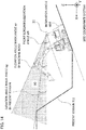
- FIG. 14 is a view of a present terrain cross section when the machine body reference azimuth angle is 15 degrees as viewed from a side.
- the elevation angle mask angle ⁇ s by the machine body (front work implement 5) in the site coordinate system can be calculated according to the following expression (1) from the front screening elevation angle ⁇ ft in the machine body coordinate system and the inclination angle ⁇ bd of the machine body calculated by the machine body IMU 21.
- ⁇ s ⁇ ft ⁇ ⁇ bd
- the elevation angle mask angle ⁇ g according to the present terrain in the site coordinate system is calculated.
- the present terrain depicted in FIG. 14 depicts a cross section of the present terrain in a direction of the machine body reference azimuth angle of 15 degrees. All straight lines that are tangential to the cross section of the present terrain are drawn from the position of the GNSS antenna 31 measured by the GNSS receiver 33, and a maximum value among angles defined by all straight lines and the horizontal plane is determined as the elevation angle mask angle ⁇ g according to the present terrain.
- the cross section of the present terrain depicted in FIG. 14 can be acquired by taking a cross section of the present terrain data in an angle direction obtained by addition of a machine body reference azimuth angle ⁇ b to an azimuth angle ⁇ t of the upper swing structure 3 calculated by the GNSS receiver 33 (namely, ⁇ t + ⁇ b).
- a greater one of the elevation angle mask angle ⁇ s by the machine body and the elevation angle mask angle ⁇ g by the present terrain calculated in such a manner as described above is determined as an elevation angle mask angle at the azimuth angle.
- ⁇ s > ⁇ g is satisfied, and therefore, the elevation angle mask angle ⁇ s by the machine body becomes the elevation angle mask angle, and the mask range 90 in the elevation angle range where the machine body reference azimuth angle is 15 degrees is as depicted in FIG. 14 .
- Similar calculation is performed for all azimuths to calculate elevation angle mask angles at all azimuths.
- a mask range is set to the site coordinate system on the basis of the resulting elevation angle mask angles. It is to be noted that it is sufficient if the mask range is set to the coordinate system set to the ground, and for example, the mask range may be set to the geographic coordinate system.
- the controller 38 adds (sums) the mask range calculated at step S50 (mask range set newly) to a mask range set before the present calculation cycle (mask range set in the past (however, except the mask ranges reset at steps S90 and S110 described hereinabove)).
- a new mask range is set according to such changes. Then, since the new mask range is added to the mask ranges in the past, the mask range is expanded according to a change in the inclination angle and the azimuth angle of the upper swing structure 3.
- the controller 38 transmits the mask range stored in the storage device to the GNSS receiver 33.
- the mask range at step S60 is transmitted to the GNSS receiver 33, and when the step 70 is reached after carrying out the step S45, the last mask range set at step S60 is transmitted (however, where the step S60 is not carried out at all after the mask range is reset at step S90 or S110, the mask range is not transmitted).
- the controller 38 decides whether or not information that position measurement cannot be performed in a state in which the mask range is set is received from the GNSS receiver 33. For this decision, a process described below is performed by the GNSS receiver 33.
- the GNSS receiver 33 receives the mask range transmitted from the controller 38 at step S70, excludes satellites that are positioned within the mask range from among a plurality of GNSS satellites from which a satellite signal can be received, and decides whether or not position measurement calculation can be performed on the basis of satellite signals transmitted from the remaining satellites.
- the GNSS receiver 33 decides that the position measurement calculation can be performed, the GNSS receiver 33 transmits information indicating that position measurement is possible in the state in which the mask range is set to the controller 38.
- the GNSS receiver 33 calculates the position of the GNSS antenna 31 and the vector from the GNSS antenna 31 to the GNSS antenna 32 and outputs a result of the calculation to the controller 38.
- the GNSS receiver 33 transmits information indicating that position measurement cannot be performed in the state in which the mask range is set to the controller 38.
- the controller 38 may acquire satellite numbers of satellites from which satellite signals can be received and information of the azimuth angle and the angle of elevation of the satellites from the GNSS receiver 33, calculate satellite numbers of satellites existing within the mask range calculated by the controller 38, and transmit the satellite numbers that are not used for position measurement calculation to the GNSS receiver 33, so that the decision described hereinabove may be carried out.
- step S80 When the information that position measurement cannot be performed in a state in which the mask range is set is received from the GNSS receiver 33 at step S80, the controller 38 advances the processing to step S90 at which to display that there is the possibility that the position measurement accuracy may be deteriorated on the screen of the display device 39 and reset the information of the mask range stored in the controller 38. Accordingly, all mask ranges are erased. It is to be noted that the time period T measured at step S45 is also reset simultaneously with the resetting of the mask range.
- step S100 when the information that position measurement is possible even in the state in which the mask range is set is received from the GNSS receiver 33 at step S80 (namely, when information that position measurement is impossible in the state in which the mask range is set is not received), the processing advances to step S100.
- the controller 38 decides whether or not it is necessary to reset (erase) the mask range. In this decision, the controller 38 decides that it is necessary to reset the mask range in any of a case in which the time period T measured at step S45 continues for a predetermined time period t1 or more (for example, for 10 minutes or more), another case in which the hydraulic excavator 1 moves by a predetermined distance or more (for example, 3 m or more) by a traveling operation for the lower track structure 2 by the operation device in the cab 4, a further case in which a demand of the operator that the mask range is to be reset is inputted through the setting switch (mask range reset switch) 40, and a still further case of a first calculation cycle immediately after system startup.
- the movement of the hydraulic excavator 1 by the traveling operation can be detected, for example, from pilot pressure detection for traveling and position movement of the hydraulic excavator 1 that is performed on the basis of position measurement calculation of the GNSS receiver 33.
- step S100 When it is decided at step S100 that it is necessary to reset the mask range, the controller 38 advances the processing to step S110 at which resetting of the mask range is performed and the time period T measured at step S45 is also reset to zero at the same time.
- a mask range according to the azimuth angle and the inclination angle of the upper swing structure 1 during a work is set to the site coordinate system, and position measurement calculation is performed by the GNSS receiver 33 without utilizing satellite signals of GNSS satellites positioned within the mask range. Consequently, it is prevented that the position measurement accuracy of the GNSS is deteriorated during a work by switching of satellites associated with operation of the front work implement 5 (principally, from boom raising operation) or diffraction of satellite signals. As a result, since the position calculation result of the monitor point is prevented from fluctuating, the control accuracy of the hydraulic excavator 1 can be improved.
- the hydraulic excavator 1 described above has such a specification that a mask range is set while a work that requires accuracy is being performed, and in a state in which a work that does not require accuracy continues for the predetermined time period t1 or more, in another state in which the measurement position accuracy is deteriorated by setting of a mask range, or in a like state, the setting of the mask range is cancelled.
- the hydraulic excavator 1 is configured such that, while a mask range is set only in a scene in which the accuracy is required to secure position measurement accuracy, in another scene in which accuracy is not required or in a further scene in which accuracy cannot be secured, immediacy not of accuracy but of position measurement is prioritized such that position measurement suitable for a scene can be performed.
- a mask range is set newly according to the change and the new mask range is added to a mask range set in the past thereby to expand the mask range.
- a mask range is set according to a change in azimuth angle of the upper swing structure 3 during the swing movement and is summed to the mask range in the past. Consequently, it can be avoided that different satellites are selected at the excavation position and the soil-dumping position, and therefore, the measurement accuracy can be prevented from being deteriorated by switching of satellites.
- a mask range can be set taking into consideration an influence by not only the front work implement 5 but also the obstacle (for example, a present terrain) on position measurement. Consequently, position measurement calculation can be performed without utilizing signals of satellites blocked by the obstacle, and therefore, the position measurement accuracy can be improved further.
- a mask range may be set in all cases.
- a configuration relating to the controller 38 described above may be a program (software) by which the functions relating to the configuration of the controlling device are implemented by an arithmetic processing unit (for example, a CPU) by reading out and executing the program.
- Information relating to the program can be stored, for example, into a semiconductor memory (flash memory, SSD, or the like), a magnetic storage device (hard disk drive or the like), a recording medium (magnetic disk, optical disc, or the like), or the like.
Landscapes
- Engineering & Computer Science (AREA)
- Radar, Positioning & Navigation (AREA)
- Remote Sensing (AREA)
- General Physics & Mathematics (AREA)
- Computer Networks & Wireless Communication (AREA)
- Physics & Mathematics (AREA)
- Structural Engineering (AREA)
- General Engineering & Computer Science (AREA)
- Civil Engineering (AREA)
- Mining & Mineral Resources (AREA)
- Position Fixing By Use Of Radio Waves (AREA)
- Operation Control Of Excavators (AREA)
- Component Parts Of Construction Machinery (AREA)
Abstract
Description
- The present invention relates to a work machine such as a hydraulic excavator, and particularly to a work machine that incorporates a position measurement system that uses satellite signals of satellites to measure an absolute position of a monitor point set to a work device in a three-dimensional space.
- In recent years, at a construction work site, it is popular to measure the position of a predetermined point (monitor point) set to a work machine, using a three-dimensional position measurement system such as a GNSS (Global Navigation Satellite System) and to perform work management. A typical example of the monitor point is a point set to a work device provided on a work machine, for example, a bucket distal end of a hydraulic excavator. If the position of the bucket distal end can be measured, by comparing measurement data by the measurement with terrain data or target shape data set in advance, a work progress situation during construction can be grasped, and accordingly, this enables management and control during construction. Further, by creating finished form data (for example, excavation terrain data) from a history of measurement data till the end of construction, construction management can be performed also after the construction.
- Incidentally, for example, in a hydraulic excavator, a work device that can be positioned higher than a GNSS antenna such as a boom, an arm, and a bucket or an obstacle around the work device becomes an obstacle to a signal (GNSS signal, satellite signal) transmitted from a GNSS satellite. Therefore, there is the possibility that the GNSS antenna may receive a GNSS signal as a diffracted wave or a reflected wave called multipath. If a diffracted wave or a reflected wave is used in position measurement of a monitor point, the possibility that a position measurement result may include an error is high. As a solution method for eliminating the influence of the multipath, for example, a solution method disclosed in
Patent Document 1 is available. -
Patent Document 1 discloses a positioning apparatus that includes a reception device receiving signals from a plurality of transmitters (a plurality of satellites) and that decides transmitter positions of the individual transmitters (the plurality of satellites). Then, the positioning apparatus calculates transmitters (a plurality of satellites) from which signals can be received directly on the basis of the positions of the transmitters, a position of the positioning apparatus decided in a preceding operation cycle, and multipath information, and decides the present position of the positioning apparatus, ignoring the transmitters from which signals cannot be received directly. - Patent Document 1:
JP-2010-534849-T - In the technology of
Patent Document 1 described above, it is possible to reduce the influence of diffraction and reflection by an obstacle. However, in a work machine that repeats a series of operations such as excavation, swing, and dumping of loaded soil like a hydraulic excavator, the relative positions of the work machine and an obstacle around the work machine can change readily according to a change in posture of the work device or an upper swing structure. Therefore, there is the possibility that the combination of satellite signals to be used for position measurement may constantly switch. The position measurement by the GNSS has a subject that, if satellites to be used for position measurement switch, the position measurement error increases. - The present invention has been made to solve the subject described above, and it is an object of the present invention to provide a work machine that can prevent accuracy degradation in GNSS position measurement even if the posture of a work device or an upper swing structure changes during work of the work machine.
- In order to achieve the object described above, according to the present invention, there is provided a work machine that includes a lower track structure, an upper swing structure swingably provided on the lower track structure and configuring a machine body together with the lower track structure, a work device rotatably provided on the upper swing structure, an inclination measurement device provided on the machine body, an angle measurement device provided on the work device, a three-dimensional position measurement device that calculates a three-dimensional position and a direction of itself on the basis of satellite signals of satellites, and a controller that calculates, on the basis of information from the inclination measurement device, the angle measurement device, and the three-dimensional position measurement device, a three-dimensional position and a posture of the machine body, and a three-dimensional position of a predetermined position of the work device, in which the three-dimensional position measurement device receives satellite signals of satellites, selects, from among the satellites whose satellite signals are received, the satellites to be used for calculation of a three-dimensional position and a direction of the three-dimensional position measurement device, and calculates a three-dimensional position and a direction of the three-dimensional position measurement device on the basis of the satellite signals of the selected satellites, and the work machine further includes a storage instruction device for instructing to store a combination of the satellites selected by the three-dimensional position measurement device. The controller stores, when the instruction is inputted through the storage instruction device, the combination of the satellites selected by the three-dimensional position measurement device as satellite selection information, and transmits, when a predetermined changing condition is satisfied, the satellite selection information to the three-dimensional measurement device, and the three-dimensional position measurement device preferentially selects, when the three-dimensional position measurement device receives the satellite selection information from the controller, the satellites included in the satellite selection information from among the satellites from which the satellite signals are received.
- According to the present invention, even if the posture of the work device or the upper swing structure changes during work, switching of the satellite signals to be used in calculation of GNSS position measurement, deterioration of the position measurement accuracy by the GNSS can be suppressed, and as a result, the work accuracy can be improved.
-
-
FIG. 1 is a view depicting an appearance of a hydraulic excavator according to an embodiment of the present invention. -
FIG. 2 is a block diagram depicting an apparatus configuration of a position measurement system incorporated in the hydraulic excavator. -
FIG. 3 is a block diagram depicting an apparatus configuration of an office side system having a role as a GNSS reference station. -
FIG. 4 is a view schematically depicting a posture of the hydraulic excavator upon excavation operation. -
FIG. 5 is a view schematically depicting a posture of the hydraulic excavator upon swing operation. -
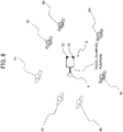
FIG. 6 is a view schematically depicting an excavation position and a soil-dumping position of the hydraulic excavator and arrangement of GNSS satellites existing in a sky view of a GNSS antenna at that time. -
FIG. 7 is a view schematically depicting an excavation position of the hydraulic excavator, arrangement of GNSS satellites existing in a sky view of the GNSS antenna at that time, and a combination of GNSS satellites used in position calculation. -
FIG. 8 is a view schematically depicting a soil-dumping position of the hydraulic excavator, arrangement of GNSS satellites existing in a sky view of the GNSS antenna at that time, and a combination of GNSS satellites used in position calculation. -
FIG. 9 is a view schematically depicting an excavation position of the hydraulic excavator, arrangement of GNSS satellites existing in a sky view of the GNSS antenna at that time, and a combination of GNSS satellites used in position calculation. -
FIG. 10 is a flow chart depicting processing of a controller. -
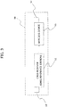
FIG. 11 is a flow chart depicting one of particular examples of a process executed at step S40 inFIG. 10 . -
FIG. 12 is a view depicting an example of a relation between a machine body reference azimuth angle and a front screening elevation angle αft. -
FIG. 13 is an explanatory view of the machine body reference azimuth angle. -
FIG. 14 is a view of a present terrain cross section when the machine body reference azimuth angle is 15 degrees as viewed from a side. -
FIG. 15 is a view depicting a relation diagram of the machine body reference azimuth angle and an azimuth angle of an upper swing structure. - In the following, an embodiment of the present invention is described with reference to the drawings. The present embodiment is an embodiment when the present invention is applied to a crawler type hydraulic excavator as a construction machine and a monitor point (control point) is set to a bucket distal end of the hydraulic excavator. It is to be noted that, in the figures, equivalent members are denoted by the same reference numerals and overlapping description is suitably omitted.
-
FIG. 1 is a view depicting an appearance of the hydraulic excavator of the present embodiment. - Referring to
FIG. 1 , thehydraulic excavator 1 includes alower track structure 2 that travels by crawlers driven by traveling hydraulic motors (not depicted), anupper swing structure 3 attached for swinging motion on thelower track structure 2 and configuring a machine body together with thelower track structure 2, acab 4 provided on theupper swing structure 3, and a front work implement (work device) 5 attached to theupper swing structure 3. Theupper swing structure 3 is driven to swing leftward and rightward by a swing hydraulic motor (not depicted). The front work implement 5 is an articulated type work apparatus including aboom 6 rotatably provided in upward and downward directions on theupper swing structure 3, anarm 7 rotatably provided in the upward and downward directions at a distal end of theboom 6, and a bucket (attachment) 8 rotatably provided in the upward and downward directions at a distal end of thearm 7. Theboom 6, thearm 7, and thebucket 8 are driven by elongating or contracting aboom cylinder 9, anarm cylinder 10, and abucket cylinder 11, respectively. Each of theboom 6, thearm 7, and thebucket 8 is sometimes referred to as a front member. - Also, a
machine body IMU 21 for detecting an inclination angle (pitch angle) of theupper swing structure 3 with respect to a predetermined plane (for example, a horizontal plane) is attached to theupper swing structure 3. Aboom IMU 22 for detecting an angle of the boom 6 (boom angle) with respect a predetermine plane (for example, the horizontal plane) is attached to theboom 6. Anarm IMU 23 for detecting an angle of the arm 7 (arm angle) with respect to a predetermined plane (for example, the horizontal plane) is attached to thearm 7. Abucket IMU 24 for detecting an angle of the bucket 8 (bucket angle) with respect to a predetermined plane (for example, the horizontal plane) is attached to thebucket 8. It is to be noted that, in the present specification, theboom IMU 22, thearm IMU 23, and thebucket IMU 24 are sometimes referred to collectively as front IMUs (refer toFIG. 2 ). - Further, on the
upper swing structure 3, twoGNSS antennae data receiving antenna 34 for receiving RTK correction data (hereinafter described) from a reference station are provided. The twoGNSS antennae upper swing structure 3. -
FIG. 2 is a block diagram of a position measurement system incorporated in thehydraulic excavator 1. The position measurement system 200 depicted inFIG. 2 includes awireless device 35, aGNSS receiver 33, acontroller 38, adisplay device 39 and a settingswitch 40. - The
wireless device 35 receives RTK correction data (hereinafter described) from a reference station through the RTK correctiondata receiving antenna 34 and outputs the RTK correction data to theGNSS receiver 33. - The GNSS
receiver 33 calculates the position of theGNSS antenna 31 that is one of the twoGNSS antennae GNSS antenna 31 that is one of the twoGNSS antennae other GNSS antenna 32 on the real time basis on the basis of RTK correction data inputted from thewireless device 35 and signals from GNSS satellites received by theGNSS antennae upper swing structure 3 in a geographic coordinate system (global coordinate system) can be calculated. - The
controller 38 receives the position and vector data calculated by theGNSS receiver 33 and angle data from theIMUs 21 to 24 as inputs thereto and calculates a position and an azimuth angle of theupper swing structure 3 and a position of the distal end (monitor point) of thebucket 8. Thecontroller 38 includes, as hardware, an arithmetic processing unit (for example, a CPU), a storage device (for example, a semiconductor memory such as a ROM and a RAM), and an interface (inputting/outputting device). In thecontroller 38, a program (software) stored in advance in the storage device is executed by the arithmetic processing unit, and arithmetic processing is performed by the arithmetic processing unit on the basis of data prescribed in the program and data inputted from the interface. Then, a signal (calculation result) is outputted from the interface to the outside. It is to be noted that, though not depicted, theGNSS receiver 33 can also include hardware similar to that of thecontroller 38. - The display device (monitor) 39 displays a calculation result of the
controller 38 and various kinds of data acquired by utilizing the calculation result. - The setting switch (masking range reset switch) 40 is connected to the
controller 38. The settingswitch 40 is a switch for cancelling (deleting) all mask ranges (hereinafter described) set at that time. The settingswitch 40 is depressed at a timing desired by an operator, and as a result, thecontroller 38 deletes all mask ranges. Details of setting of a mask range and a scene in which the settingswitch 40 is utilized are hereinafter described. - In addition, an external recording medium (external storage device) 42 such as a semiconductor memory can be connected to the
controller 38. Theexternal recording medium 42 has stored therein terrain data including present terrain data and target terrain data (also referred to as design data). The operator connects theexternal recording medium 42 to thecontroller 38 at a predetermined timing such as at the time of system startup and downloads, when necessary, data into a storage device in thecontroller 38. Then, at the time of end of a work or the like, for example, present terrain data after the work created from locus data on the bucket distal end position while the system is operating is recorded into theexternal recording medium 42 and is used in work management. -
FIG. 3 is a block diagram of an office side measurement system (reference station system) 50 having a role as a GNSS reference station. - Referring to
FIG. 3 , the officeside measurement system 50 includes aGNSS antenna 52, aGNSS receiver 51, awireless device 53, and awireless antenna 54. - The
GNSS antenna 52 is an antenna for receiving satellite signals (navigation signals) transmitted from a plurality of GNSS satellites. - The
GNSS receiver 51 functions as a GNSS reference station (in the following description, theGNSS receiver 51 is sometimes represented as a GNSS reference station 51), and generates, on the basis of data on a three-dimensional position measured in advance (for example, the position of the GNSS antenna 52) and satellite signals received by theGNSS antenna 52, correction data for allowing theGNSS receiver 33 of thehydraulic excavator 1 to perform RTK (real time kinematic) measurement, and outputs the correction data to thewireless device 53. - The
wireless device 53 transmits the correction data inputted from theGNSS receiver 51 to thewireless device 35 of thehydraulic excavator 1 through thewireless antenna 54. - Now, an overview of operation of the position measurement system 200 according to the present embodiment is described.
- In the present embodiment, in order to perform position measurement with high accuracy, RTK measurement is performed by the
GNSS receiver 33 depicted inFIG. 2 . To this end, theGNSS reference station 51 that creates correction data depicted inFIG. 3 is first required. TheGNSS reference station 51 creates correction data for RTK measurement on the basis of the position data on theGNSS antenna 52 three-dimensionally measured in advance as described hereinabove and satellite signals from a plurality of GNSS satellites received by theGNSS antenna 52, and transmits the created correction data by thewireless device 53 in a fixed cycle through theantenna 54. - On the other hand, the
GNSS receiver 33 on thehydraulic excavator 1 side depicted inFIG. 2 performs RTK measurement on the three-dimensional position of theGNSS antenna 31 and the vector from theGNSS antenna 31 to theGNSS antenna 32 on the basis of the correction data received from thewireless device 35 through theantenna 34 and satellite signals from a plurality of GNSS satellites received by theGNSS antennae GNSS antenna 31 in the geographic coordinate system and the vector from theGNSS antenna 31 to theGNSS antenna 32 are measured with high accuracy. Then, the measured three-dimensional position data and vector data are inputted to thecontroller 38. - Meanwhile, the inclination angle of the hydraulic excavator 1 (upper swing structure 3) (namely, a pitch angle and a roll angle) and the angles of the
boom 6, thearm 7, and thebucket 8 are measured by theIMUs 21 to 24 and are similarly inputted to thecontroller 38. - The
controller 38 performs general vector calculation and coordinate transformation on the basis of the various kinds of inputted data to calculate a position and a posture (including an azimuth angle) of theupper swing structure 3 and the position of the distal end (monitor point) of thebucket 8 in a predetermined coordinate system (for example, a site coordinate system set to the ground of the work site). In addition, it is also possible for thecontroller 38 to display an image of the bucket and a target terrain on the screen of thedisplay device 39 on the basis of the calculated position and posture of theupper swing structure 3 and the calculated position of the distal end of thebucket 8, and the target terrain data inputted from the external recording medium 41 to notify the operator of the work situation. - Now, deterioration of reproducibility of position measurement by the
GNSS receiver 33, which is the subject of the present invention, is described with reference toFIGS. 4 to 9 . -
FIG. 4 schematically depicts a posture of thehydraulic excavator 1 upon excavation operation. Referring toFIG. 4 , thehydraulic excavator 1 performs a generally-called slope face forming work. The image depicted inFIG. 4 is generally equivalent to information displayed on thedisplay device 39, and the operator will perform an excavation operation of thehydraulic excavator 1 on the basis of this information such that apresent terrain 61 approaches atarget terrain 62. -
FIG. 5 schematically depicts a posture of thehydraulic excavator 1 upon swing operation. As depicted inFIG. 5 , usually the swing operation is performed in a state in which theboom 6 is raised after excavation operation ends, thearm 7 and thebucket 8 are moved inward, and a clearance between thebucket 8 and the ground is secured. Then, thearm 7 and thebucket 8 are dumped at a soil-dumping position to release the excavated soil down to a predetermined position. Thereafter, swing operation for returning to the excavation position is performed, and the excavation operation is repeated. -
FIG. 6 schematically depicts an excavation position and a soil-dumping position of thehydraulic excavator 1 and arrangement ofGNSS satellites 81 to 87 existing within a sky view of theGNSS antennae FIG. 6 , a state in which the front work implement 5 is directed to the upper side is defined as anexcavation position 71, and a state in which the front work implement 5 is directed to the left side is defined as a soil-dumpingposition 72. Also, it is assumed that movement from theexcavation position 71 to the soil-dumpingposition 72 is performed by left swing and movement from the soil-dumpingposition 72 to theexcavation position 71 is performed by right swing. - In position measurement by the GNSS, the
GNSS receiver 33 performs various condition decisions regarding the quality of satellite signals from GNSS satellites received by theGNSS antennae - Here, the arrangement of GNSS satellites is evaluated with a numerical value called DOP (Dilution of Precision), and, for example, in such a case that GNSS satellites are distributed so as to be clustered to one direction of the sky view, the DOP is bad (the numerical value is high). As a result, the position accuracy in calculation is deteriorated. In contrast, where GNSS satellites are distributed without being clustered to the one direction in the sky view, the DOP is good (the numerical value is low), and the position accuracy in calculation is improved. This arises from that position measurement by the GNSS is a measurement system that applies triangulation.
- Therefore, where the
GNSS satellites 81 to 87 which can be caught are arranged in such arrangement as indicated inFIG. 6 , as GNSS satellites to be used for position calculation at theexcavation position 71, for example, thesatellites FIG. 7 are selected. - However, when the excavation operation of the
hydraulic excavator 1 ends and thehydraulic excavator 1 takes such a swing posture as depicted inFIG. 5 and swings leftward from theexcavation position 71 to the soil-dumpingposition 72, then since the front work implement 5 passes between theGNSS antennae GNSS satellites GNSS satellites - As a result, at the time of position calculation of the soil-dumping
position 72, for example, theGNSS satellites 82 to 85 indicated with hatched lines inFIG. 8 are selected, and the GNSS satellites sometimes change from those of the combination selected at theexcavation position 71 inFIG. 7 . - Further, the
hydraulic excavator 1 returns to theexcavation position 71 by right swing and repeats the excavation operation. However, while thehydraulic excavator 1 swings rightward from the soil-dumpingposition 72 to theexcavation position 71, since the satellite signals of theGNSS satellites 82 to 85 are not blocked by the front work implement 5, the combination of GNSS satellites to be used for position calculation is kept to be theGNSS satellites 82 to 85 also at theexcavation position 71 as depicted inFIG. 9 . Consequently, the change from the combination of theGNSS satellites - In position measurement by the GNSS, not only DOP but also error factors that are subtly different among GNSS satellites, such as a clock error among GNSS satellites or an error of orbit information are involved, and even if the
hydraulic excavator 1 is positioned at the same position, if the combination of GNSS satellites to be used for position calculation differs, a displacement appears in position calculation results, resulting in the possibility that the reproducibility of position calculation may be deteriorated. - If the reproducibility of position calculation by the
GNSS receiver 33 is deteriorated in this manner, then there is the possibility that the positional relation between thebucket 8 and thetarget terrain 62 displayed on thedisplay device 39 may become different before and after excavation operation, and as a result, such a problem that the finished form becomes discontinuous may possibly occur. - Selection logic of satellites to be used which is to be executed by the
controller 38 in a method for solving the problem just described is described with reference to a flow chart ofFIG. 10. FIG. 10 is a flow chart depicting an example of the satellite selection logic to be executed by thecontroller 38. It is to be noted that the flow chart ofFIG. 10 is calculated repeatedly in a fixed cycle (for example, 100 ms). - At step S10, the
controller 38 decides whether a Fix solution is obtained by RTK based on information from theGNSS receiver 33. Whether or not this state is achieved can be decided by referring to, for example, a GGA sentence of an NMEA message from theGNSS receiver 33. - When it is decided at step S10 that a Fix solution is not obtained, the
controller 38 decides that correct position measurement has not been performed, and the processing advances to step S20 at which thecontroller 38 displays on thedisplay device 39 that correct measurement is not performed and returns to an initial state (waits till a next control cycle). On the other hand, when it is decided at step S10 that a Fix solution is obtained, the processing advances to step S30. - At step S30, the
controller 38 performs, on the basis of a three-dimensional position of theGNSS antenna 31 inputted from theGNSS receiver 33, vector information from theGNSS antenna 31 to theGNSS antenna 32, and angle information inputted from theIMUs 21 to 24, general vector calculation and coordinate transformation to calculate the position and the posture of theupper swing structure 3 and the position of the distal end of thebucket 8 in the site coordinate system. Then, thecontroller 38 displays posture information of thebucket 8, a present terrain generated on the basis of terrain data acquired from theexternal recording medium 42 and information of a target shape on thedisplay device 39. - Then, the processing advances to step S40 at which the
controller 38 decides by a decision method depicted inFIG. 11 whether or not thehydraulic excavator 1 is performing a work that requires accuracy. Here, the logic (decision logic) of thecontroller 38 for deciding whether or not thehydraulic excavator 1 is performing an excavation work that requires accuracy at step S40 is described with reference toFIG. 11. FIG. 11 is a flow chart depicting one of particular examples of the process performed at step S40. - First at step S401, the
controller 38 decides whether or not the distance between the front work implement 5 and a target surface (target surface distance) is equal to or smaller than a predetermined value d1. As the target surface distance, for example, the distance between the bucket distal end (claw tip) position and the target surface can be used. In this case, a perpendicular line is drawn from the position of the bucket distal end (monitor point) calculated at step S30, a point at which the perpendicular line crosses with the target terrain surface defined by the target terrain data is calculated, and the distance between the point and the bucket distal end can be determined as the target surface distance. When the target surface distance is greater than the predetermined value d1, thecontroller 38 decides that, because the bucket distal end is at a position spaced away from the target surface, an excavation work that requires accuracy is not being performed. On the other hand, when it is the decision that the target surface distance is equal to or smaller than the predetermined value d1, the processing advances to step S402. - At step S402, the
controller 38 decides whether or not an excavation operation is inputted to an operation device (not depicted) for operating the front work implement 5 (theboom 6, thearm 7, and the bucket 8) installed in thecab 4. Whether or not an excavation operation is inputted is decided here depending upon whether or not the arm 7 (arm cylinder 10) is being driven. Whether or not the arm 7 (arm cylinder 10) is being driven can be decided, for example, by detecting the operation pilot pressure of thearm 7 outputted from the operation device by a pressure sensor and checking whether or not the detected pressure exceeds a predetermined value. - When an affirmative result is obtained both at steps S401 and S402 in this manner, the
controller 38 deems that thehydraulic excavator 1 is performing an excavation work that requires accuracy. In this manner, even if the distance between the bucket distal end and the target surface is equal to or smaller than the predetermined value d1 at step S401, when it is decided at step S402 that an excavation operation is not being performed, for example, in such a state in which thearm 7 stops with the distal end of thebucket 8 contacting with the terrain excavated according to the target surface, a decision that an excavation work is not being performed is made. Therefore, a mask range hereinafter described can be prevented from being widened more than necessary. Further, when it is decided at step S401 that the target surface distance exceeds the predetermined value d1, for example, also when a rough finish work is being performed, the mask range hereinafter described can be prevented from being widened more than necessary. It is to be noted that, although it has been assumed that the decision of an excavation operation is decided only from the operation pilot pressure of the arm, decision of an excavation operation may be made additionally on the basis of the operation pilot pressure of theboom 6 or thebucket 8. Further, the decision may be made taking not only an instantaneous value but also continuity of the operation pilot pressure in the past (namely, a time series of the detected operation pilot pressure), and the like into consideration. Further, not the operation pilot pressure, but, for example, an excavation reactive force or the like acting upon thearm cylinder 10 may be detected by a pressure sensor installed in thearm cylinder 10 to decide an excavation operation. Further, although it is decided here on the basis of both of the magnitude of the target surface distance (step S401) and the presence/absence of an excavation operation (step S402) whether or not thehydraulic excavator 1 is performing a work that requires accuracy, the decision may be made on one of these two processes (steps S401 and S402). In other words, the decision may be made based on at least one of the two processes. - Referring back to
FIG. 7 , when it is decided at step S40 that thehydraulic excavator 1 is not performing a work that requires accuracy, the processing advances to step S45. At step S45, thecontroller 38 starts measurement of a time period (duration) T during which the state in which it is decided that thehydraulic excavator 1 is not performing a work that requires accuracy continues, and then, the processing advances to step S70. It is to be noted that, when measurement of the time period T is already started at the time of reaching step S45, the measurement is assumed to be continued. - On the other hand, when it is decided at step S40 that the
hydraulic excavator 1 is performing a work that requires accuracy, the processing advances to step S50. - At step S50, the
controller 38 sets a range within which, when each of the twoGNSS antennae GNSS receiver 33. In other words, a range of satellite arrangement that is not to be used for position measurement is calculated at step S50. - The
controller 38 of the present embodiment sets a mask range at step S50 on the basis of the installation positions of the twoGNSS antennae controller 38 in advance, a movable range of the front work implement 5 (boom 6,arm 7, and bucket 8), an inclination angle of theupper swing structure 3 detected by themachine body IMU 21, and an azimuth angle of theupper swing structure 3 calculated from the vector information from theGNSS antenna 31 to theGNSS antenna 32. The mask range is set for each of the twoGNSS antennae GNSS antennae - Further, when it is possible at step S50 to acquire shape data on obstacles (for example, a present terrain, buildings, and structures) that exist around the
hydraulic excavator 1 and can become obstacles to satellite signals (shape data includes also positions), thecontroller 38 can set also a range within which satellite signals can be blocked by the obstacles as a mask range in addition to the setting of the mask range arising from the front work implement 5 described above. For example, a mask range may be set in the following manner. Present terrain data from theexternal recording medium 42 is stored in advance as shape data on obstacles in the storage device in thecontroller 38. Then at step S50, thecontroller 38 calculates, on the basis of the position, azimuth angle and inclination angle of theupper swing structure 3 in the geographic coordinate system (global coordinate system), installation positions of the twoGNSS antennae upper swing structure 3. Then, thecontroller 38 further takes into consideration a range within which the present terrain that has the cross sectional shape when each of the twoGNSS antennae - Here, an example of the calculation process of a mask range at step S50 is described with reference to
FIGS. 12 to 15 . Although calculation of a mask range for theGNSS antenna 31 is described for the convenience of description, a mask range for theGNSS antenna 32 can also be calculated by a similar method. - For the elevation angle mask angle that defines an elevation angle range of a mask range, a direction from the horizontal plane to the sky is defined as a positive direction, and the zenith direction is defined as an elevation angle of 90 degrees. Therefore, as the elevation angle mask angle, the lower end is 0 degrees, and the upper end is 90 degrees in the maximum. Further, the azimuth angle mask angle that defines an azimuth angle range of a mask range is defined as a range from 0 degrees to 360 degrees with the north direction defined as 0 degrees and the clockwise direction defined as a positive direction.
- In the storage device of the
controller 38, an screened portion of the front work implement 5 as viewed from theGNSS antenna 31 is stored as a front screening elevation angle αft for each azimuth angle with reference to the machine body (machine body reference azimuth angle).FIG. 12 is a view depicting an example of a relation between the machine body reference azimuth angle and the front screening elevation angle αft, and a front screening elevation angle αft is set for each machine body reference azimuth angle. For each machine body reference azimuth angle, a range equal to or smaller than the front screening elevation angle αft becomes a range (mask range) within which a satellite signal is blocked. The machine body reference azimuth angle and the front screening elevation angle αft here are defined in the machine body coordinate system set to theupper swing structure 3. If, as depicted inFIG. 13 , using theGNSS antenna 31 as a reference, the forward direction of thehydraulic excavator 1 is defined as machine body reference azimuth angle of 0 degrees and the clockwise direction is a positive direction, the front screening elevation angle αft is defined at intervals of 5 degrees while the machine body reference azimuth angle reaches 360 degrees from 0 degrees. In the example ofFIG. 12 , since the front work implement 5 does not become an obstacle to satellite signals except a range of the machine body reference azimuth angle from 10 degrees to 25 degrees, the front screening elevation angle is 0 degrees. The range of the machine body reference azimuth angle from 10 degrees to 25 degrees is indicated as a mask range (azimuth angle range) 90 inFIG. 13 . It is to be noted that the front screening elevation angle αft may be defined from a maximum movable range of each of thefront members - Here, for explanation, calculation of an elevation angle mask angle of an influence by the machine body when the machine body reference azimuth angle is 15 degrees is described with reference to
FIG. 14 . -
FIG. 14 is a view of a present terrain cross section when the machine body reference azimuth angle is 15 degrees as viewed from a side. As depicted in the figure, the elevation angle mask angle αs by the machine body (front work implement 5) in the site coordinate system can be calculated according to the following expression (1) from the front screening elevation angle αft in the machine body coordinate system and the inclination angle αbd of the machine body calculated by themachine body IMU 21.
- Then, the elevation angle mask angle αg according to the present terrain in the site coordinate system is calculated. The present terrain depicted in
FIG. 14 depicts a cross section of the present terrain in a direction of the machine body reference azimuth angle of 15 degrees. All straight lines that are tangential to the cross section of the present terrain are drawn from the position of theGNSS antenna 31 measured by theGNSS receiver 33, and a maximum value among angles defined by all straight lines and the horizontal plane is determined as the elevation angle mask angle αg according to the present terrain. - It is to be noted that, since the present terrain data is represented in the site coordinate system in which the north azimuth is defined as 0 degrees (reference) as depicted in
FIG. 15 , the cross section of the present terrain depicted inFIG. 14 can be acquired by taking a cross section of the present terrain data in an angle direction obtained by addition of a machine body reference azimuth angle αb to an azimuth angle αt of theupper swing structure 3 calculated by the GNSS receiver 33 (namely, αt + αb). - A greater one of the elevation angle mask angle αs by the machine body and the elevation angle mask angle αg by the present terrain calculated in such a manner as described above is determined as an elevation angle mask angle at the azimuth angle. In the example in
FIG. 14 , αs > αg is satisfied, and therefore, the elevation angle mask angle αs by the machine body becomes the elevation angle mask angle, and themask range 90 in the elevation angle range where the machine body reference azimuth angle is 15 degrees is as depicted inFIG. 14 . Similar calculation is performed for all azimuths to calculate elevation angle mask angles at all azimuths. Then, a mask range is set to the site coordinate system on the basis of the resulting elevation angle mask angles. It is to be noted that it is sufficient if the mask range is set to the coordinate system set to the ground, and for example, the mask range may be set to the geographic coordinate system. - Referring back to
FIG. 10 , at step S60, thecontroller 38 adds (sums) the mask range calculated at step S50 (mask range set newly) to a mask range set before the present calculation cycle (mask range set in the past (however, except the mask ranges reset at steps S90 and S110 described hereinabove)). By this step S60, for example, when the inclination angle of theupper swing structure 3 changes after the process one cycle before or when the azimuth angle changes as a result of swing motion of theupper swing structure 3, a new mask range is set according to such changes. Then, since the new mask range is added to the mask ranges in the past, the mask range is expanded according to a change in the inclination angle and the azimuth angle of theupper swing structure 3. - At step S70, the
controller 38 transmits the mask range stored in the storage device to theGNSS receiver 33. When the step S70 is reached after carrying out the step 60, the mask range at step S60 is transmitted to theGNSS receiver 33, and when thestep 70 is reached after carrying out the step S45, the last mask range set at step S60 is transmitted (however, where the step S60 is not carried out at all after the mask range is reset at step S90 or S110, the mask range is not transmitted). - At step S80, the
controller 38 decides whether or not information that position measurement cannot be performed in a state in which the mask range is set is received from theGNSS receiver 33. For this decision, a process described below is performed by theGNSS receiver 33. In particular, theGNSS receiver 33 receives the mask range transmitted from thecontroller 38 at step S70, excludes satellites that are positioned within the mask range from among a plurality of GNSS satellites from which a satellite signal can be received, and decides whether or not position measurement calculation can be performed on the basis of satellite signals transmitted from the remaining satellites. When theGNSS receiver 33 decides that the position measurement calculation can be performed, theGNSS receiver 33 transmits information indicating that position measurement is possible in the state in which the mask range is set to thecontroller 38. Further, theGNSS receiver 33 calculates the position of theGNSS antenna 31 and the vector from theGNSS antenna 31 to theGNSS antenna 32 and outputs a result of the calculation to thecontroller 38. On the other hand, when position measurement calculation cannot be performed because the number of satellites to be used is insufficient (for example, less than five) as a result of setting of the mask range or because the arrangement of satellites to be used is biased (for example, the DOP is equal to or higher than a predetermined value), causing a risk of accuracy reduction, in order to allow position measurement calculation to be performed in a state in which the mask range is cancelled at step S90 hereinafter described, theGNSS receiver 33 transmits information indicating that position measurement cannot be performed in the state in which the mask range is set to thecontroller 38. - It is to be noted that, although a case in which an azimuth angle range and an elevation angle range to be masked are calculated by the
controller 38 and the ranges (mask range) are transmitted to theGNSS receiver 33 has been described here, thecontroller 38 may acquire satellite numbers of satellites from which satellite signals can be received and information of the azimuth angle and the angle of elevation of the satellites from theGNSS receiver 33, calculate satellite numbers of satellites existing within the mask range calculated by thecontroller 38, and transmit the satellite numbers that are not used for position measurement calculation to theGNSS receiver 33, so that the decision described hereinabove may be carried out. - When the information that position measurement cannot be performed in a state in which the mask range is set is received from the
GNSS receiver 33 at step S80, thecontroller 38 advances the processing to step S90 at which to display that there is the possibility that the position measurement accuracy may be deteriorated on the screen of thedisplay device 39 and reset the information of the mask range stored in thecontroller 38. Accordingly, all mask ranges are erased. It is to be noted that the time period T measured at step S45 is also reset simultaneously with the resetting of the mask range. On the other hand, when the information that position measurement is possible even in the state in which the mask range is set is received from theGNSS receiver 33 at step S80 (namely, when information that position measurement is impossible in the state in which the mask range is set is not received), the processing advances to step S100. - At step S100, the
controller 38 decides whether or not it is necessary to reset (erase) the mask range. In this decision, thecontroller 38 decides that it is necessary to reset the mask range in any of a case in which the time period T measured at step S45 continues for a predetermined time period t1 or more (for example, for 10 minutes or more), another case in which thehydraulic excavator 1 moves by a predetermined distance or more (for example, 3 m or more) by a traveling operation for thelower track structure 2 by the operation device in thecab 4, a further case in which a demand of the operator that the mask range is to be reset is inputted through the setting switch (mask range reset switch) 40, and a still further case of a first calculation cycle immediately after system startup. The movement of thehydraulic excavator 1 by the traveling operation can be detected, for example, from pilot pressure detection for traveling and position movement of thehydraulic excavator 1 that is performed on the basis of position measurement calculation of theGNSS receiver 33. - When it is decided at step S100 that it is necessary to reset the mask range, the
controller 38 advances the processing to step S110 at which resetting of the mask range is performed and the time period T measured at step S45 is also reset to zero at the same time. - By carrying out the processing described above, when a work that requires accuracy is being performed by the
hydraulic excavator 1, satellite signals that may possibly be influenced by an obstacle including the front work implement 5 are not used for position measurement calculation. Therefore, deterioration in the accuracy in position measurement calculation due to switching of the combination of satellites to be used for position measurement calculation on the way of excavation can be prevented, and deterioration in the accuracy in position measurement calculation due to use of a satellite signal influenced by diffraction of radio waves can be prevented. - In the
hydraulic excavator 1 configured in such a manner as described above, a mask range according to the azimuth angle and the inclination angle of theupper swing structure 1 during a work is set to the site coordinate system, and position measurement calculation is performed by theGNSS receiver 33 without utilizing satellite signals of GNSS satellites positioned within the mask range. Consequently, it is prevented that the position measurement accuracy of the GNSS is deteriorated during a work by switching of satellites associated with operation of the front work implement 5 (principally, from boom raising operation) or diffraction of satellite signals. As a result, since the position calculation result of the monitor point is prevented from fluctuating, the control accuracy of thehydraulic excavator 1 can be improved. - Especially, the
hydraulic excavator 1 described above has such a specification that a mask range is set while a work that requires accuracy is being performed, and in a state in which a work that does not require accuracy continues for the predetermined time period t1 or more, in another state in which the measurement position accuracy is deteriorated by setting of a mask range, or in a like state, the setting of the mask range is cancelled. In particular, thehydraulic excavator 1 is configured such that, while a mask range is set only in a scene in which the accuracy is required to secure position measurement accuracy, in another scene in which accuracy is not required or in a further scene in which accuracy cannot be secured, immediacy not of accuracy but of position measurement is prioritized such that position measurement suitable for a scene can be performed. - Further, in the
hydraulic excavator 1 described above, when the azimuth angle or the inclination angle of theupper swing structure 3 changes, a mask range is set newly according to the change and the new mask range is added to a mask range set in the past thereby to expand the mask range. In particular, for example, when theupper swing structure 3 swings from an excavation position to a soil-dumping position, a mask range is set according to a change in azimuth angle of theupper swing structure 3 during the swing movement and is summed to the mask range in the past. Consequently, it can be avoided that different satellites are selected at the excavation position and the soil-dumping position, and therefore, the measurement accuracy can be prevented from being deteriorated by switching of satellites. - Further, if shape data on an obstacle is stored in advance in the
controller 38, then a mask range can be set taking into consideration an influence by not only the front work implement 5 but also the obstacle (for example, a present terrain) on position measurement. Consequently, position measurement calculation can be performed without utilizing signals of satellites blocked by the obstacle, and therefore, the position measurement accuracy can be improved further. - Although the embodiment of the present invention has been described in detail above, the present invention is not restricted to the embodiment described above but includes various modifications. For example, the embodiment described above has been described in detail in order to explain the present invention in an easy-to-understand manner and is not necessarily limited to what includes all configurations described above.
- For example, although, in the flow chart of
FIG. 10 described above, presence or absence of setting of a mask range is switched depending upon whether or not a work that requires accuracy is being performed, a mask range may be set in all cases. - Further, the individual configurations relating to the controller (control device) 38 described above and the functions, execution processes, and so forth of the individual configurations may be partly or entirely implemented by hardware (for example, by designing the logic for executing the functions with an integrated circuit). Further, a configuration relating to the
controller 38 described above may be a program (software) by which the functions relating to the configuration of the controlling device are implemented by an arithmetic processing unit (for example, a CPU) by reading out and executing the program. Information relating to the program can be stored, for example, into a semiconductor memory (flash memory, SSD, or the like), a magnetic storage device (hard disk drive or the like), a recording medium (magnetic disk, optical disc, or the like), or the like. - Further, although, in the description of each embodiment described above, those of controls lines and information lines considered necessary for description of the embodiment are described, all of control lines and information lines relating to a product are not necessarily indicated. It may be considered that actually almost all configurations are connected to each other.
-
- 1:
- Hydraulic excavator (work machine)
- 2:
- Lower track structure
- 3:
- Upper swing structure
- 4:
- Cab
- 5:
- Front work implement (work device)
- 6:
- Boom
- 7:
- Arm
- 8:
- Bucket
- 9:
- Boom cylinder
- 10:
- Arm cylinder
- 11:
- Bucket cylinder
- 21:
- Machine body IMU
- 22:
- Boom IMU
- 23:
- Arm IMU
- 24:
- Bucket IMU
- 31, 32:
- GNSS antenna
- 33:
- GNSS receiver
- 34:
- RTK correction data receiving antenna
- 39:
- Display device
- 40:
- Setting switch (mask range reset switch)
- 42:
- External recording medium
- 50:
- Office side measurement system
- 51:
- GNSS reference station (GNSS receiver)
- 52:
- GNSS reference station antenna
- 53:
- Wireless device
- 54:
- RTK correction data transmission antenna
- 61:
- Present terrain
- 62:
- Target terrain
- 71:
- Excavation position
- 72:
- Soil-dumping position
- 81 to 87:
- GNSS satellite
- 200:
- Position measurement system
Claims (6)
- A work machine that includes a track structure, an upper swing structure swingably attached on the track structure, a work device attached to the upper swing structure, two GNSS antennae installed on the upper swing structure, a receiver configured to calculate a position and an azimuth angle of the upper swing structure on a basis of satellite signals transmitted from a plurality of satellites and received by the two GNSS antennae, and a controller configured to calculate a position of a monitor point on a basis of the position and the azimuth angle of the upper swing structure calculated by the receiver, whereinthe controller is configured to set, on a basis of installation positions of the two GNSS antennae on the work machine, a movable range of the work device, an inclination angle of the upper swing structure, and an azimuth angle of the upper swing structure, a range within which, when the two GNSS antennae individually receive satellite signals from the plurality of satellites, the work device possibly becomes an obstacle to the satellite signals as a mask range in a coordinate system set to a ground, andthe receiver is configured to calculate a position and an azimuth angle of the upper swing structure on a basis of the satellite signals transmitted from remaining ones of the plurality of satellites, the remaining ones other than the satellites positioned within the mask range set by the controller.
- The work machine according to claim 1, wherein
the controller decides whether or not the work machine is performing a work that requires accuracy and sets the mask range when the controller decides that the work machine is performing a work that requires accuracy. - The work machine according to claim 2, wherein
the controller cancels the setting of the mask range when any one of a case in which a state that it is decided that the work machine is not performing a work that requires accuracy continues for a predetermined period of time or more, another case in which the work machine moves a predetermined distance or more, and a further case in which a position of the upper swing structure is not able to be calculated with satellite signals transmitted from the remaining satellites is applicable. - The work machine according to claim 1, wherein
the controller decides whether or not the work machine is performing a work that requires accuracy on a basis of at least one of a distance between the work device and a target surface and an inputting operation to an operation device that operates the work device, and sets the mask range when the controller decides that the work machine is performing a work that requires accuracy. - The work machine according to claim 1, wherein
the controller is configured to newly set the mask range according to a change in the inclination angle and the azimuth angle of the upper swing structure and is configured to add the new mask range to the mask range set in a past. - The work machine according to claim 1, whereinthe controller includes a storage device in which shape data on an obstacle around the work machine is stored, andthe controller is configured to calculate, on a basis of the position and the azimuth angle of the upper swing structure and the shape data on the obstacle, a cross sectional shape when the obstacle is cut in a predetermined azimuth angle direction with reference to the azimuth angle of the upper swing structure and is configured to set the mask range further taking into consideration an influence by the obstacle having the cross sectional shape when the two GNSS antennae individually receive satellite signals from the plurality of satellites.
Applications Claiming Priority (2)
| Application Number | Priority Date | Filing Date | Title |
|---|---|---|---|
| JP2019038047A JP6961636B2 (en) | 2019-03-01 | 2019-03-01 | Work machine |
| PCT/JP2020/004152 WO2020179320A1 (en) | 2019-03-01 | 2020-02-04 | Working machine |
Publications (3)
| Publication Number | Publication Date |
|---|---|
| EP3933122A1 true EP3933122A1 (en) | 2022-01-05 |
| EP3933122A4 EP3933122A4 (en) | 2022-12-07 |
| EP3933122B1 EP3933122B1 (en) | 2024-09-04 |
Family
ID=72280228
Family Applications (1)
| Application Number | Title | Priority Date | Filing Date |
|---|---|---|---|
| EP20766596.9A Active EP3933122B1 (en) | 2019-03-01 | 2020-02-04 | Working machine |
Country Status (6)
| Country | Link |
|---|---|
| US (1) | US12000114B2 (en) |
| EP (1) | EP3933122B1 (en) |
| JP (1) | JP6961636B2 (en) |
| KR (1) | KR102500969B1 (en) |
| CN (1) | CN112639225B (en) |
| WO (1) | WO2020179320A1 (en) |
Cited By (1)
| Publication number | Priority date | Publication date | Assignee | Title |
|---|---|---|---|---|
| EP4317617A4 (en) * | 2021-03-30 | 2025-02-12 | Hitachi Construction Machinery Co., Ltd. | Work machine |
Families Citing this family (9)
| Publication number | Priority date | Publication date | Assignee | Title |
|---|---|---|---|---|
| JP7088691B2 (en) * | 2018-02-28 | 2022-06-21 | 株式会社小松製作所 | Loading machine control, control method and remote control system |
| JP7419119B2 (en) * | 2020-03-16 | 2024-01-22 | 日立建機株式会社 | working machine |
| US20230168387A1 (en) * | 2020-04-28 | 2023-06-01 | Nippon Telegraph And Telephone Corporation | Measurement apparatus, measurement method and program |
| JP2022111857A (en) * | 2021-01-20 | 2022-08-01 | 日立建機株式会社 | Satellite positioning system and server equipment |
| JP7691869B2 (en) * | 2021-07-08 | 2025-06-12 | 株式会社小松製作所 | CONTROL SYSTEM FOR WORK MACHINE, CONTROL MACHINE, AND CONTROL METHOD FOR WORK MACHINE |
| JP7850047B2 (en) * | 2022-09-29 | 2026-04-22 | 日立建機株式会社 | Construction accuracy prediction calculation device for industrial machinery |
| JP2024055416A (en) * | 2022-10-07 | 2024-04-18 | 兵庫県公立大学法人 | Working machine and position detection device |
| KR20250141215A (en) * | 2023-03-31 | 2025-09-26 | 히다찌 겐끼 가부시키가이샤 | Construction machinery and remote control systems |
| JP2025037181A (en) | 2023-09-05 | 2025-03-17 | コベルコ建機株式会社 | Location determining system, location determining device, and location determining method |
Family Cites Families (17)
| Publication number | Priority date | Publication date | Assignee | Title |
|---|---|---|---|---|
| DE4011316A1 (en) * | 1990-04-07 | 1991-10-17 | Rheinische Braunkohlenw Ag | Satellite geodesy system for excavator shovel wheel position |
| JPH0462490A (en) * | 1990-06-29 | 1992-02-27 | Nippondenso Co Ltd | Gps receiving device for vehicle |
| DE4415083A1 (en) | 1994-04-29 | 1995-11-02 | Bosch Gmbh Robert | Procedure for the selection of signals from navigation satellites |
| JP2003004838A (en) * | 2001-06-27 | 2003-01-08 | Nec Eng Ltd | Gps receiver |
| JP3816806B2 (en) * | 2002-01-21 | 2006-08-30 | 株式会社トプコン | Construction machine control system |
| EP1804071B1 (en) | 2005-12-29 | 2008-10-15 | Alcatel Lucent | Method for optimising positioning data processing where there are several satellite positioning constellations |
| WO2009017393A1 (en) | 2007-07-31 | 2009-02-05 | Tele Atlas B.V. | Method and device for determining a position |
| US8232916B2 (en) * | 2009-05-05 | 2012-07-31 | Trimble Navigation Limited | Tilt compensation for GNSS antenna |
| JP5059953B2 (en) * | 2011-02-22 | 2012-10-31 | 株式会社小松製作所 | Work range display device for hydraulic excavator and control method thereof |
| CN103454650B (en) * | 2013-08-20 | 2015-06-24 | 北京航空航天大学 | Method for monitoring satellite integrity with vision as auxiliary |
| US9644346B2 (en) | 2014-05-14 | 2017-05-09 | Komatsu Ltd. | Calibration system and calibration method for excavator |
| JP2016079677A (en) * | 2014-10-16 | 2016-05-16 | 日立建機株式会社 | Area limited excavation control device and construction machine |
| EP3059611A1 (en) * | 2015-02-12 | 2016-08-24 | Agco Corporation | Gnss-based obstruction mapping |
| EP3064964B1 (en) | 2015-03-04 | 2018-08-29 | AGCO Corporation | Path planning based on obstruction mapping |
| JP2016188792A (en) * | 2015-03-30 | 2016-11-04 | 独立行政法人交通安全環境研究所 | Position measuring method and position measuring system |
| US10145088B2 (en) * | 2015-05-29 | 2018-12-04 | Komatsu Ltd. | Control system of work machine and work machine |
| DE102015016045B8 (en) * | 2015-12-11 | 2017-09-14 | Audi Ag | Satellite-based determination of a motor vehicle in a covered area |
-
2019
- 2019-03-01 JP JP2019038047A patent/JP6961636B2/en active Active
-
2020
- 2020-02-04 EP EP20766596.9A patent/EP3933122B1/en active Active
- 2020-02-04 CN CN202080004684.6A patent/CN112639225B/en active Active
- 2020-02-04 KR KR1020217005192A patent/KR102500969B1/en active Active
- 2020-02-04 US US17/274,448 patent/US12000114B2/en active Active
- 2020-02-04 WO PCT/JP2020/004152 patent/WO2020179320A1/en not_active Ceased
Cited By (1)
| Publication number | Priority date | Publication date | Assignee | Title |
|---|---|---|---|---|
| EP4317617A4 (en) * | 2021-03-30 | 2025-02-12 | Hitachi Construction Machinery Co., Ltd. | Work machine |
Also Published As
| Publication number | Publication date |
|---|---|
| US12000114B2 (en) | 2024-06-04 |
| WO2020179320A1 (en) | 2020-09-10 |
| KR20210034065A (en) | 2021-03-29 |
| EP3933122B1 (en) | 2024-09-04 |
| CN112639225B (en) | 2022-09-13 |
| JP6961636B2 (en) | 2021-11-05 |
| EP3933122A4 (en) | 2022-12-07 |
| CN112639225A (en) | 2021-04-09 |
| US20220025615A1 (en) | 2022-01-27 |
| KR102500969B1 (en) | 2023-02-17 |
| JP2020139933A (en) | 2020-09-03 |
Similar Documents
| Publication | Publication Date | Title |
|---|---|---|
| EP3933122B1 (en) | Working machine | |
| EP4036324B1 (en) | Work machine | |
| KR102606049B1 (en) | construction machinery | |
| EP1630636B1 (en) | Dynamic stabilization and control of an earthmoving machine | |
| US12209392B2 (en) | Work machine | |
| JP7007313B2 (en) | Work machine | |
| US12146291B2 (en) | Work machine | |
| EP3303772B1 (en) | Adaptation of mining operations satellite coverage | |
| CN112654750A (en) | Working machine | |
| EP4166725A1 (en) | Construction machine | |
| EP4350395A1 (en) | Electronic control device | |
| EP4019704A1 (en) | Penetration monitoring control system and work machine | |
| KR20230044508A (en) | work machine | |
| JP6910995B2 (en) | Work machine | |
| JP7500420B2 (en) | Work Machine | |
| JP2024052345A (en) | Work Machine | |
| JP2026062325A (en) | GNSS field reference station for work machines |
Legal Events
| Date | Code | Title | Description |
|---|---|---|---|
| STAA | Information on the status of an ep patent application or granted ep patent |
Free format text: STATUS: THE INTERNATIONAL PUBLICATION HAS BEEN MADE |
|
| PUAI | Public reference made under article 153(3) epc to a published international application that has entered the european phase |
Free format text: ORIGINAL CODE: 0009012 |
|
| STAA | Information on the status of an ep patent application or granted ep patent |
Free format text: STATUS: REQUEST FOR EXAMINATION WAS MADE |
|
| 17P | Request for examination filed |
Effective date: 20211001 |
|
| AK | Designated contracting states |
Kind code of ref document: A1 Designated state(s): AL AT BE BG CH CY CZ DE DK EE ES FI FR GB GR HR HU IE IS IT LI LT LU LV MC MK MT NL NO PL PT RO RS SE SI SK SM TR |
|
| DAV | Request for validation of the european patent (deleted) | ||
| DAX | Request for extension of the european patent (deleted) | ||
| A4 | Supplementary search report drawn up and despatched |
Effective date: 20221108 |
|
| RIC1 | Information provided on ipc code assigned before grant |
Ipc: G01S 19/54 20100101ALI20221102BHEP Ipc: G01S 19/28 20100101ALI20221102BHEP Ipc: E02F 9/26 20060101AFI20221102BHEP |
|
| GRAP | Despatch of communication of intention to grant a patent |
Free format text: ORIGINAL CODE: EPIDOSNIGR1 |
|
| STAA | Information on the status of an ep patent application or granted ep patent |
Free format text: STATUS: GRANT OF PATENT IS INTENDED |
|
| INTG | Intention to grant announced |
Effective date: 20240411 |
|
| GRAS | Grant fee paid |
Free format text: ORIGINAL CODE: EPIDOSNIGR3 |
|
| GRAA | (expected) grant |
Free format text: ORIGINAL CODE: 0009210 |
|
| STAA | Information on the status of an ep patent application or granted ep patent |
Free format text: STATUS: THE PATENT HAS BEEN GRANTED |
|
| AK | Designated contracting states |
Kind code of ref document: B1 Designated state(s): AL AT BE BG CH CY CZ DE DK EE ES FI FR GB GR HR HU IE IS IT LI LT LU LV MC MK MT NL NO PL PT RO RS SE SI SK SM TR |
|
| REG | Reference to a national code |
Ref country code: GB Ref legal event code: FG4D |
|
| REG | Reference to a national code |
Ref country code: CH Ref legal event code: EP |
|
| REG | Reference to a national code |
Ref country code: IE Ref legal event code: FG4D |
|
| REG | Reference to a national code |
Ref country code: DE Ref legal event code: R096 Ref document number: 602020037147 Country of ref document: DE |
|
| REG | Reference to a national code |
Ref country code: LT Ref legal event code: MG9D |
|
| REG | Reference to a national code |
Ref country code: NL Ref legal event code: MP Effective date: 20240904 |
|
| PG25 | Lapsed in a contracting state [announced via postgrant information from national office to epo] |
Ref country code: NO Free format text: LAPSE BECAUSE OF FAILURE TO SUBMIT A TRANSLATION OF THE DESCRIPTION OR TO PAY THE FEE WITHIN THE PRESCRIBED TIME-LIMIT Effective date: 20241204 |
|
| PG25 | Lapsed in a contracting state [announced via postgrant information from national office to epo] |
Ref country code: GR Free format text: LAPSE BECAUSE OF FAILURE TO SUBMIT A TRANSLATION OF THE DESCRIPTION OR TO PAY THE FEE WITHIN THE PRESCRIBED TIME-LIMIT Effective date: 20241205 Ref country code: PL Free format text: LAPSE BECAUSE OF FAILURE TO SUBMIT A TRANSLATION OF THE DESCRIPTION OR TO PAY THE FEE WITHIN THE PRESCRIBED TIME-LIMIT Effective date: 20240904 Ref country code: FI Free format text: LAPSE BECAUSE OF FAILURE TO SUBMIT A TRANSLATION OF THE DESCRIPTION OR TO PAY THE FEE WITHIN THE PRESCRIBED TIME-LIMIT Effective date: 20240904 |
|
| PG25 | Lapsed in a contracting state [announced via postgrant information from national office to epo] |
Ref country code: BG Free format text: LAPSE BECAUSE OF FAILURE TO SUBMIT A TRANSLATION OF THE DESCRIPTION OR TO PAY THE FEE WITHIN THE PRESCRIBED TIME-LIMIT Effective date: 20240904 |
|
| PG25 | Lapsed in a contracting state [announced via postgrant information from national office to epo] |
Ref country code: LV Free format text: LAPSE BECAUSE OF FAILURE TO SUBMIT A TRANSLATION OF THE DESCRIPTION OR TO PAY THE FEE WITHIN THE PRESCRIBED TIME-LIMIT Effective date: 20240904 |
|
| PG25 | Lapsed in a contracting state [announced via postgrant information from national office to epo] |
Ref country code: HR Free format text: LAPSE BECAUSE OF FAILURE TO SUBMIT A TRANSLATION OF THE DESCRIPTION OR TO PAY THE FEE WITHIN THE PRESCRIBED TIME-LIMIT Effective date: 20240904 |
|
| PG25 | Lapsed in a contracting state [announced via postgrant information from national office to epo] |
Ref country code: ES Free format text: LAPSE BECAUSE OF FAILURE TO SUBMIT A TRANSLATION OF THE DESCRIPTION OR TO PAY THE FEE WITHIN THE PRESCRIBED TIME-LIMIT Effective date: 20240904 Ref country code: RS Free format text: LAPSE BECAUSE OF FAILURE TO SUBMIT A TRANSLATION OF THE DESCRIPTION OR TO PAY THE FEE WITHIN THE PRESCRIBED TIME-LIMIT Effective date: 20241204 |
|
| PG25 | Lapsed in a contracting state [announced via postgrant information from national office to epo] |
Ref country code: RS Free format text: LAPSE BECAUSE OF FAILURE TO SUBMIT A TRANSLATION OF THE DESCRIPTION OR TO PAY THE FEE WITHIN THE PRESCRIBED TIME-LIMIT Effective date: 20241204 Ref country code: PL Free format text: LAPSE BECAUSE OF FAILURE TO SUBMIT A TRANSLATION OF THE DESCRIPTION OR TO PAY THE FEE WITHIN THE PRESCRIBED TIME-LIMIT Effective date: 20240904 Ref country code: NO Free format text: LAPSE BECAUSE OF FAILURE TO SUBMIT A TRANSLATION OF THE DESCRIPTION OR TO PAY THE FEE WITHIN THE PRESCRIBED TIME-LIMIT Effective date: 20241204 Ref country code: LV Free format text: LAPSE BECAUSE OF FAILURE TO SUBMIT A TRANSLATION OF THE DESCRIPTION OR TO PAY THE FEE WITHIN THE PRESCRIBED TIME-LIMIT Effective date: 20240904 Ref country code: HR Free format text: LAPSE BECAUSE OF FAILURE TO SUBMIT A TRANSLATION OF THE DESCRIPTION OR TO PAY THE FEE WITHIN THE PRESCRIBED TIME-LIMIT Effective date: 20240904 Ref country code: GR Free format text: LAPSE BECAUSE OF FAILURE TO SUBMIT A TRANSLATION OF THE DESCRIPTION OR TO PAY THE FEE WITHIN THE PRESCRIBED TIME-LIMIT Effective date: 20241205 Ref country code: FI Free format text: LAPSE BECAUSE OF FAILURE TO SUBMIT A TRANSLATION OF THE DESCRIPTION OR TO PAY THE FEE WITHIN THE PRESCRIBED TIME-LIMIT Effective date: 20240904 Ref country code: ES Free format text: LAPSE BECAUSE OF FAILURE TO SUBMIT A TRANSLATION OF THE DESCRIPTION OR TO PAY THE FEE WITHIN THE PRESCRIBED TIME-LIMIT Effective date: 20240904 Ref country code: BG Free format text: LAPSE BECAUSE OF FAILURE TO SUBMIT A TRANSLATION OF THE DESCRIPTION OR TO PAY THE FEE WITHIN THE PRESCRIBED TIME-LIMIT Effective date: 20240904 |
|
| REG | Reference to a national code |
Ref country code: AT Ref legal event code: MK05 Ref document number: 1720532 Country of ref document: AT Kind code of ref document: T Effective date: 20240904 |
|
| PG25 | Lapsed in a contracting state [announced via postgrant information from national office to epo] |
Ref country code: NL Free format text: LAPSE BECAUSE OF FAILURE TO SUBMIT A TRANSLATION OF THE DESCRIPTION OR TO PAY THE FEE WITHIN THE PRESCRIBED TIME-LIMIT Effective date: 20240904 |
|
| PG25 | Lapsed in a contracting state [announced via postgrant information from national office to epo] |
Ref country code: IS Free format text: LAPSE BECAUSE OF FAILURE TO SUBMIT A TRANSLATION OF THE DESCRIPTION OR TO PAY THE FEE WITHIN THE PRESCRIBED TIME-LIMIT Effective date: 20250104 Ref country code: PT Free format text: LAPSE BECAUSE OF FAILURE TO SUBMIT A TRANSLATION OF THE DESCRIPTION OR TO PAY THE FEE WITHIN THE PRESCRIBED TIME-LIMIT Effective date: 20250106 |
|
| PG25 | Lapsed in a contracting state [announced via postgrant information from national office to epo] |
Ref country code: RO Free format text: LAPSE BECAUSE OF FAILURE TO SUBMIT A TRANSLATION OF THE DESCRIPTION OR TO PAY THE FEE WITHIN THE PRESCRIBED TIME-LIMIT Effective date: 20240904 Ref country code: SM Free format text: LAPSE BECAUSE OF FAILURE TO SUBMIT A TRANSLATION OF THE DESCRIPTION OR TO PAY THE FEE WITHIN THE PRESCRIBED TIME-LIMIT Effective date: 20240904 |
|
| PG25 | Lapsed in a contracting state [announced via postgrant information from national office to epo] |
Ref country code: EE Free format text: LAPSE BECAUSE OF FAILURE TO SUBMIT A TRANSLATION OF THE DESCRIPTION OR TO PAY THE FEE WITHIN THE PRESCRIBED TIME-LIMIT Effective date: 20240904 Ref country code: AT Free format text: LAPSE BECAUSE OF FAILURE TO SUBMIT A TRANSLATION OF THE DESCRIPTION OR TO PAY THE FEE WITHIN THE PRESCRIBED TIME-LIMIT Effective date: 20240904 |
|
| PG25 | Lapsed in a contracting state [announced via postgrant information from national office to epo] |
Ref country code: CZ Free format text: LAPSE BECAUSE OF FAILURE TO SUBMIT A TRANSLATION OF THE DESCRIPTION OR TO PAY THE FEE WITHIN THE PRESCRIBED TIME-LIMIT Effective date: 20240904 |
|
| PG25 | Lapsed in a contracting state [announced via postgrant information from national office to epo] |
Ref country code: SK Free format text: LAPSE BECAUSE OF FAILURE TO SUBMIT A TRANSLATION OF THE DESCRIPTION OR TO PAY THE FEE WITHIN THE PRESCRIBED TIME-LIMIT Effective date: 20240904 Ref country code: IT Free format text: LAPSE BECAUSE OF FAILURE TO SUBMIT A TRANSLATION OF THE DESCRIPTION OR TO PAY THE FEE WITHIN THE PRESCRIBED TIME-LIMIT Effective date: 20240904 |
|
| REG | Reference to a national code |
Ref country code: DE Ref legal event code: R097 Ref document number: 602020037147 Country of ref document: DE |
|
| PG25 | Lapsed in a contracting state [announced via postgrant information from national office to epo] |
Ref country code: DK Free format text: LAPSE BECAUSE OF FAILURE TO SUBMIT A TRANSLATION OF THE DESCRIPTION OR TO PAY THE FEE WITHIN THE PRESCRIBED TIME-LIMIT Effective date: 20240904 |
|
| PLBE | No opposition filed within time limit |
Free format text: ORIGINAL CODE: 0009261 |
|
| STAA | Information on the status of an ep patent application or granted ep patent |
Free format text: STATUS: NO OPPOSITION FILED WITHIN TIME LIMIT |
|
| 26N | No opposition filed |
Effective date: 20250605 |
|
| PG25 | Lapsed in a contracting state [announced via postgrant information from national office to epo] |
Ref country code: SE Free format text: LAPSE BECAUSE OF FAILURE TO SUBMIT A TRANSLATION OF THE DESCRIPTION OR TO PAY THE FEE WITHIN THE PRESCRIBED TIME-LIMIT Effective date: 20240904 |
|
| PG25 | Lapsed in a contracting state [announced via postgrant information from national office to epo] |
Ref country code: MC Free format text: LAPSE BECAUSE OF FAILURE TO SUBMIT A TRANSLATION OF THE DESCRIPTION OR TO PAY THE FEE WITHIN THE PRESCRIBED TIME-LIMIT Effective date: 20240904 |
|
| REG | Reference to a national code |
Ref country code: CH Ref legal event code: PL |
|
| PG25 | Lapsed in a contracting state [announced via postgrant information from national office to epo] |
Ref country code: LU Free format text: LAPSE BECAUSE OF NON-PAYMENT OF DUE FEES Effective date: 20250204 |
|
| PG25 | Lapsed in a contracting state [announced via postgrant information from national office to epo] |
Ref country code: CH Free format text: LAPSE BECAUSE OF NON-PAYMENT OF DUE FEES Effective date: 20250228 |
|
| REG | Reference to a national code |
Ref country code: BE Ref legal event code: MM Effective date: 20250228 |
|
| PG25 | Lapsed in a contracting state [announced via postgrant information from national office to epo] |
Ref country code: FR Free format text: LAPSE BECAUSE OF NON-PAYMENT OF DUE FEES Effective date: 20250228 |
|
| PG25 | Lapsed in a contracting state [announced via postgrant information from national office to epo] |
Ref country code: BE Free format text: LAPSE BECAUSE OF NON-PAYMENT OF DUE FEES Effective date: 20250228 |
|
| PG25 | Lapsed in a contracting state [announced via postgrant information from national office to epo] |
Ref country code: IE Free format text: LAPSE BECAUSE OF NON-PAYMENT OF DUE FEES Effective date: 20250204 |
|
| PGFP | Annual fee paid to national office [announced via postgrant information from national office to epo] |
Ref country code: GB Payment date: 20260106 Year of fee payment: 7 |
|
| PGFP | Annual fee paid to national office [announced via postgrant information from national office to epo] |
Ref country code: DE Payment date: 20251230 Year of fee payment: 7 |