EP3932799A1 - Rotor retention fitting with integral bearing and pitch control - Google Patents
Rotor retention fitting with integral bearing and pitch control Download PDFInfo
- Publication number
- EP3932799A1 EP3932799A1 EP21162406.9A EP21162406A EP3932799A1 EP 3932799 A1 EP3932799 A1 EP 3932799A1 EP 21162406 A EP21162406 A EP 21162406A EP 3932799 A1 EP3932799 A1 EP 3932799A1
- Authority
- EP
- European Patent Office
- Prior art keywords
- aperture
- rotor
- inboard
- plate
- bearing assembly
- Prior art date
- Legal status (The legal status is an assumption and is not a legal conclusion. Google has not performed a legal analysis and makes no representation as to the accuracy of the status listed.)
- Granted
Links
Images


Classifications
-
- B—PERFORMING OPERATIONS; TRANSPORTING
- B64—AIRCRAFT; AVIATION; COSMONAUTICS
- B64C—AEROPLANES; HELICOPTERS
- B64C11/00—Propellers, e.g. of ducted type; Features common to propellers and rotors for rotorcraft
- B64C11/02—Hub construction
- B64C11/04—Blade mountings
- B64C11/06—Blade mountings for variable-pitch blades
-
- F—MECHANICAL ENGINEERING; LIGHTING; HEATING; WEAPONS; BLASTING
- F16—ENGINEERING ELEMENTS AND UNITS; GENERAL MEASURES FOR PRODUCING AND MAINTAINING EFFECTIVE FUNCTIONING OF MACHINES OR INSTALLATIONS; THERMAL INSULATION IN GENERAL
- F16C—SHAFTS; FLEXIBLE SHAFTS; ELEMENTS OR CRANKSHAFT MECHANISMS; ROTARY BODIES OTHER THAN GEARING ELEMENTS; BEARINGS
- F16C33/00—Parts of bearings; Special methods for making bearings or parts thereof
- F16C33/02—Parts of sliding-contact bearings
- F16C33/04—Brasses; Bushes; Linings
- F16C33/06—Sliding surface mainly made of metal
-
- B—PERFORMING OPERATIONS; TRANSPORTING
- B64—AIRCRAFT; AVIATION; COSMONAUTICS
- B64C—AEROPLANES; HELICOPTERS
- B64C11/00—Propellers, e.g. of ducted type; Features common to propellers and rotors for rotorcraft
- B64C11/30—Blade pitch-changing mechanisms
- B64C11/32—Blade pitch-changing mechanisms mechanical
-
- B—PERFORMING OPERATIONS; TRANSPORTING
- B64—AIRCRAFT; AVIATION; COSMONAUTICS
- B64C—AEROPLANES; HELICOPTERS
- B64C27/00—Rotorcraft; Rotors peculiar thereto
- B64C27/32—Rotors
-
- B—PERFORMING OPERATIONS; TRANSPORTING
- B64—AIRCRAFT; AVIATION; COSMONAUTICS
- B64C—AEROPLANES; HELICOPTERS
- B64C27/00—Rotorcraft; Rotors peculiar thereto
- B64C27/32—Rotors
- B64C27/37—Rotors having articulated joints
- B64C27/45—Rotors having articulated joints with a feathering hinge only
-
- B—PERFORMING OPERATIONS; TRANSPORTING
- B64—AIRCRAFT; AVIATION; COSMONAUTICS
- B64C—AEROPLANES; HELICOPTERS
- B64C27/00—Rotorcraft; Rotors peculiar thereto
- B64C27/32—Rotors
- B64C27/46—Blades
- B64C27/473—Constructional features
- B64C27/48—Root attachment to rotor head
-
- B—PERFORMING OPERATIONS; TRANSPORTING
- B64—AIRCRAFT; AVIATION; COSMONAUTICS
- B64C—AEROPLANES; HELICOPTERS
- B64C27/00—Rotorcraft; Rotors peculiar thereto
- B64C27/54—Mechanisms for controlling blade adjustment or movement relative to rotor head, e.g. lag-lead movement
-
- F—MECHANICAL ENGINEERING; LIGHTING; HEATING; WEAPONS; BLASTING
- F01—MACHINES OR ENGINES IN GENERAL; ENGINE PLANTS IN GENERAL; STEAM ENGINES
- F01D—NON-POSITIVE DISPLACEMENT MACHINES OR ENGINES, e.g. STEAM TURBINES
- F01D25/00—Component parts, details, or accessories, not provided for in, or of interest apart from, other groups
- F01D25/16—Arrangement of bearings; Supporting or mounting bearings in casings
-
- F—MECHANICAL ENGINEERING; LIGHTING; HEATING; WEAPONS; BLASTING
- F16—ENGINEERING ELEMENTS AND UNITS; GENERAL MEASURES FOR PRODUCING AND MAINTAINING EFFECTIVE FUNCTIONING OF MACHINES OR INSTALLATIONS; THERMAL INSULATION IN GENERAL
- F16C—SHAFTS; FLEXIBLE SHAFTS; ELEMENTS OR CRANKSHAFT MECHANISMS; ROTARY BODIES OTHER THAN GEARING ELEMENTS; BEARINGS
- F16C17/00—Sliding-contact bearings for exclusively rotary movement
- F16C17/02—Sliding-contact bearings for exclusively rotary movement for radial load only
-
- F—MECHANICAL ENGINEERING; LIGHTING; HEATING; WEAPONS; BLASTING
- F16—ENGINEERING ELEMENTS AND UNITS; GENERAL MEASURES FOR PRODUCING AND MAINTAINING EFFECTIVE FUNCTIONING OF MACHINES OR INSTALLATIONS; THERMAL INSULATION IN GENERAL
- F16C—SHAFTS; FLEXIBLE SHAFTS; ELEMENTS OR CRANKSHAFT MECHANISMS; ROTARY BODIES OTHER THAN GEARING ELEMENTS; BEARINGS
- F16C2380/00—Electrical apparatus
- F16C2380/26—Dynamo-electric machines or combinations therewith, e.g. electro-motors and generators
Definitions
- the present disclosure relates generally to a rotor system and more particularly, but not by way of limitation, to a retention fitting integral bearing and pitch control.
- Rotor systems are used in a variety of aircraft to provide thrust to propel the aircraft through the air. Most rotor systems allow for some adjustability of rotor speed and/or rotor pitch to manipulate the amount of thrust generated by the rotors. For example, helicopters often employ one main rotor system to provide thrust. During normal operation, helicopters maintain a constant rotor speed and adjust the amount (i.e., collective control) and direction (i.e., cyclic control) of thrust generated by the rotor system by changing the pitch of the rotors. The amount of thrust produced by the main rotor system is varied by changing the pitch of the rotors using collective pitch control (i.e., the pitch of the rotors is altered in unison).
- collective pitch control i.e., the pitch of the rotors is altered in unison.
- cyclic pitch control i.e., the pitch of the rotors is altered sequentially to create a thrust vector.
- Helicopters also often employ a tail fan system to counter torque effects from the main rotor system and to provide direction control. In contrast to main rotors, tail fans only use collective pitch control and do not include cyclic control.
- Speed-based control of thrust generation of the main rotor system is not typically appropriate for use in helicopters for several reasons. For example, speed-based control is slower to react compared to pitch-based control as the rotational inertia of the rotor system makes it difficult to quickly change the speed of the rotor system.
- speed-based control of thrust generation could be used for the tail fan system of a helicopter and may also be desirable in other aircraft applications, such as, for example, airplanes and multi-rotor aircraft.
- An example of an inboard bearing assembly includes a fitting and a race.
- the fitting includes a plate with a convex mating surface and a first aperture formed through the plate for receiving a blade root of a rotor blade.
- the flange extends from the plate and includes a pitch arm.
- the race includes a second aperture formed through the race and a concave mating surface that receives the convex mating surface of the plate.
- An example of a bearing system includes an inboard bearing assembly and an outboard bearing assembly.
- the inboard bearing assembly includes an inboard fitting and an inboard race.
- the inboard fitting includes a plate with a convex mating surface and a first aperture formed through the plate for receiving a blade root of a rotor blade.
- the inboard race comprising a concave mating surface configured to receive the convex mating surface a second aperture formed the inboard race.
- the outboard bearing assembly includes an outboard bearing assembly comprising an outboard fitting having an aperture formed therethrough for receiving the blade root of the rotor blade.
- a rotor system includes a rotor hub comprising an arm extending radially outward, a yoke disposed within the rotor hub, a rotor blade having a blade root that extends through the arm of the rotor hub, and an inboard bearing assembly that couples the rotor blade to the yoke.
- the inboard bearing assembly includes an inboard fitting having a plate with a convex mating surface and a first aperture formed through the plate for receiving the blade root, and a pitch arm coupled to the plate and comprising a second aperture having a central axis that is offset from a central axis of the first aperture.
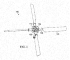
- FIG. 1 illustrates a rotor system 100, according to aspects of the disclosure.
- Rotor system 100 may be incorporated into a variety of aircraft and watercraft.
- rotor system 100 may be used as a tail fan system in a helicopter.
- Other applications for rotor system 100 include airplanes, multi-rotor aircraft, boats (e.g., propeller systems), and other rotor/propeller systems that use speed to vary the amount of thrust generated by the rotor/propeller systems.
- One particular application of rotor system 100 is for use with multi-rotor aircraft that utilize electric motors to power rotor system 100.
- Examples of multi-rotor aircraft include drones and passenger aircraft that include two or more rotors powered by electric motor(s).
- electric motors are able to more quickly vary the amount of torque provided to the rotor system, and thus can more quickly alter the speed of the rotor system.
- the quick responsiveness of the electric motor makes it an ideal power source for speed-based control of thrust generated by rotor system 100.
- Rotor system 100 is connected to a control tube 102 and a mast.
- the mast is hidden from view to more clearly illustrate control tube 102 that is concentrically disposed within the mast.
- the mast is coupled to yoke 104 and supplies torque to rotor system 100 from a power source.
- the power source may be, for example, an electric motor, gas turbine, or the like.
- Yoke 104 includes a plurality of arms 106, each of which receives a rotor blade 108. Pitch of rotor blades 108 may be collectively changed by moving a crosshead 110 that is coupled to control tube 102. To alter the pitch of rotor blades 108, control tube 102 is moved axially within the mast to displace crosshead 110 axially.
- Each rotor blade 108 is coupled to an arm 111 of crosshead 110 (see FIG. 3 ) so that axial displacement of crosshead 110 pitches rotor blades 108. Pitch control of rotor blades 108 is discussed in more detail below.
- FIG. 2 is an exploded assembly of rotor system 100, according to aspects of the disclosure.
- Each rotor blade 108 is secured to yoke 104 via an outboard bearing assembly 114 and an inboard bearing assembly 120.
- Outboard bearing assembly 114 includes a race 116 and a fitting 118. Race 116 is secured within a bore 107 of arm 106 and fitting 118 is secured to a blade root 112 of rotor blade 108.
- Outboard bearing assembly 114 allows rotor blade 108 to axially rotate within arm 106 so that a pitch of rotor blade 108 may be varied.
- Race 116 acts as a bearing race for fitting 118 and may be secured within bore 107 in a variety of ways.
- race 116 is secured within bore 107 via one or more retaining rings that fit into grooves formed into the wall of bore 107.
- retaining rings may be placed on either side of race 116 to hold race 116 in place within bore 107.
- arm 106 may include a shoulder against which one side of race 116 may abut.
- a retaining ring may be used on the other side of race 116 to secure race 116 between the shoulder and the retaining ring.
- race 116 may be fixed to bore 107 via an adhesive.
- Race 116 may be made from nylon, Teflon, steel, aluminum, copper alloys such as brass and bronze, sintered metals impregnated with lubricant such as graphite, composite materials such as glass or carbon reinforced plastics, or a combination of these materials depending on the loading and desired wear characteristics.
- race 116 may include a coating to improve hardness and/or reduce friction.
- Fitting 118 may be secured to blade root 112 in a variety of ways. In some aspects, fitting 118 is secured to blade root 112 via an adhesive. In other aspects, fitting 118 may be integrally formed as a part of blade root 112. Fitting 118 may be made from aluminum, glass-reinforced plastic, carbon-reinforced plastic, and the like. In some aspects, fitting 118 may include a coating to improve hardness and/or reduce friction. In some aspects, fitting 118 includes a lip 119 that has a diameter that is larger than a diameter of bore 107 to act as a stop to prevent rotor blade 108 from sliding farther into bore 107.
- fitting 118 does not include lip 119 and is instead restrained from moving further into bore 107 by a retaining ring that is seated in a groove formed into fitting 118.
- the retaining ring is also used to help secure race 116 within bore 107.
- Inboard bearing assembly 120 includes a fitting 122 and a race 124.
- FIGS. 3 and 4 show more detailed views of inboard bearing assembly 120.
- FIG. 3 is a perspective view of inboard bearing assembly 120 seated in yoke 104 and
- FIG. 4 is an exploded assembly of fitting 122 and race 124.
- Fitting 122 includes a plate 126 with an aperture 128 through which an end of blade root 112 passes.
- Race 124 similarly includes an aperture 125 that is coaxial with aperture 128.
- the end of blade root 112 is secured to inboard bearing assembly 120 via a flange 130 that is attached to plate 126.
- Flange 130 includes two ears 132, 134 arranged on opposite sides of aperture 128. In some aspects, flange 130 may have a single ear.
- Blade root 112 is secured to flange 130 via a fastener (e.g., a bolt or pin) that passes through apertures 138, 139 of flange 130 and an aperture 140 (best seen in FIG. 2 ) formed through the end of blade root 112.
- a fastener e.g., a bolt or pin
- Plate 126 includes a face 142 that mates with a face 144 of race 124.
- face 142 is spherical and convex and face 144 is complementarily spherical and concave to receive face 142.
- spherical surfaces for faces 142, 144 permits inboard bearing assembly 120 to both rotate about a central axis running through blade root 112 (i.e., to pitch) and to pivot off axis to allow some in-plane and out-of-plane movement of rotor blade 108.
- faces 142, 144 may have conical surfaces. Conical surfaces still permit blade root 112 to rotate about the central axis of blade root 112, but do not permit blade root 112 to pivot off axis.
- Inboard bearing assembly 120 resists centrifugal force that acts upon rotor blade 108 while rotor system 100 rotates.
- the centrifugal force acting upon rotor blade 108 is a radial force that tends to pull rotor blade 108 out of bore 107.
- inboard bearing assembly 120 does not restrain rotor blade 108 from sliding toward crosshead 110.
- Lip 119 of outboard bearing assembly 114 which is secured to blade root 112, acts as a stop to prevent rotor blade 108 from sliding into crosshead 110.
- Flange 130 includes a pitch arm 146 that extends from ear 132.
- Pitch arm 146 includes an aperture 148 that receives a fastener 150 to couple pitch arm 146 to crosshead 110.
- Fastener 150 may be a bolt, pin, link, or the like.
- Crosshead 110 includes a plurality of arms 111, with one arm 111 for each rotor blade 108.
- Each arm 111 includes an aperture 152 through which fastener 150 passes to connect crosshead 110 to pitch arm 146.
- Aperture 152 includes a race that provides a bearing surface for a spherical bearing 156 (see FIG. 4 ) that is positioned on fastener 150. In some aspects, the race may be removed and the wall of aperture 152 may be used as the bearing surface.
- Spherical bearing 156 allows for some axial misalignment between fastener 150 and blade root 112.
- a central axis of aperture 152 is offset from the central axis of blade root 112 and apertures 125, 128 so that axially displacing crosshead 110 (e.g., axial displacement coaxial to control tube 102) causes rotor blade 108 to pitch.
- substantially is defined as largely but not necessarily wholly what is specified (and includes what is specified; e.g., substantially 90 degrees includes 90 degrees and substantially parallel includes parallel), as understood by a person of ordinary skill in the art.
- the terms “substantially,” “approximately,” “generally,” and “about” may be substituted with “within [a percentage] of' what is specified, where the percentage includes 0.1, 1, 5, and 10 percent.
Landscapes
- Engineering & Computer Science (AREA)
- Mechanical Engineering (AREA)
- Aviation & Aerospace Engineering (AREA)
- General Engineering & Computer Science (AREA)
- Structures Of Non-Positive Displacement Pumps (AREA)
Abstract
Description
- The present disclosure relates generally to a rotor system and more particularly, but not by way of limitation, to a retention fitting integral bearing and pitch control.
- This section provides background information to facilitate a better understanding of the various aspects of the disclosure. It should be understood that the statements in this section of this document are to be read in this light, and not as admissions of prior art.
- Rotor systems are used in a variety of aircraft to provide thrust to propel the aircraft through the air. Most rotor systems allow for some adjustability of rotor speed and/or rotor pitch to manipulate the amount of thrust generated by the rotors. For example, helicopters often employ one main rotor system to provide thrust. During normal operation, helicopters maintain a constant rotor speed and adjust the amount (i.e., collective control) and direction (i.e., cyclic control) of thrust generated by the rotor system by changing the pitch of the rotors. The amount of thrust produced by the main rotor system is varied by changing the pitch of the rotors using collective pitch control (i.e., the pitch of the rotors is altered in unison). The direction of travel of the helicopter is controlled using cyclic pitch control (i.e., the pitch of the rotors is altered sequentially to create a thrust vector). Helicopters also often employ a tail fan system to counter torque effects from the main rotor system and to provide direction control. In contrast to main rotors, tail fans only use collective pitch control and do not include cyclic control.
- While helicopters typically rely upon collective pitch control to vary the thrust of the main rotor system and tail fan system, some aircraft instead alter the speed of the rotor system to control the amount of thrust generated by the rotor system. Speed-based control of thrust generation of the main rotor system is not typically appropriate for use in helicopters for several reasons. For example, speed-based control is slower to react compared to pitch-based control as the rotational inertia of the rotor system makes it difficult to quickly change the speed of the rotor system. However, speed-based control of thrust generation could be used for the tail fan system of a helicopter and may also be desirable in other aircraft applications, such as, for example, airplanes and multi-rotor aircraft.
- This summary is provided to introduce a selection of concepts that are further described below in the detailed description. This summary is not intended to identify key or essential features of the claimed subject matter, nor is it to be used as an aid in limiting the scope of the claimed subject matter.
- An example of an inboard bearing assembly includes a fitting and a race. The fitting includes a plate with a convex mating surface and a first aperture formed through the plate for receiving a blade root of a rotor blade. The flange extends from the plate and includes a pitch arm. The race includes a second aperture formed through the race and a concave mating surface that receives the convex mating surface of the plate.
- An example of a bearing system includes an inboard bearing assembly and an outboard bearing assembly. The inboard bearing assembly includes an inboard fitting and an inboard race. The inboard fitting includes a plate with a convex mating surface and a first aperture formed through the plate for receiving a blade root of a rotor blade. The inboard race comprising a concave mating surface configured to receive the convex mating surface a second aperture formed the inboard race. The outboard bearing assembly includes an outboard bearing assembly comprising an outboard fitting having an aperture formed therethrough for receiving the blade root of the rotor blade.
- A rotor system includes a rotor hub comprising an arm extending radially outward, a yoke disposed within the rotor hub, a rotor blade having a blade root that extends through the arm of the rotor hub, and an inboard bearing assembly that couples the rotor blade to the yoke. The inboard bearing assembly includes an inboard fitting having a plate with a convex mating surface and a first aperture formed through the plate for receiving the blade root, and a pitch arm coupled to the plate and comprising a second aperture having a central axis that is offset from a central axis of the first aperture.
- The disclosure is best understood from the following detailed description when read with the accompanying figures. It is emphasized that, in accordance with standard practice in the industry, various features are not drawn to scale. In fact, the dimensions of various features may be arbitrarily increased or reduced for clarity of discussion.
-
FIG. 1 illustrates a rotor system, according to aspects of the disclosure; -
FIG. 2 is an exploded assembly of the rotor system ofFIG. 1 , according to aspects of the disclosure; -
FIG. 3 is a partial perspective view of a rotor hub, according to aspects of the disclosure; and -
FIG. 4 is a perspective view of a bearing assembly, according to aspects of the disclosure. - It is to be understood that the following disclosure provides many different aspects, or examples, for implementing different features of various embodiments. Specific examples of components and arrangements are described below to simplify the disclosure. These are, of course, merely examples and are not intended to be limiting. In addition, the disclosure may repeat reference numerals and/or letters in the various examples. This repetition is for the purpose of simplicity and clarity and does not in itself dictate a relationship between the various embodiments and/or configurations discussed.
- In the specification, reference may be made to the spatial relationships between various components and to the spatial orientation of various aspects of components as the devices are depicted in the attached drawings. However, as will be recognized by those skilled in the art after a complete reading of the present disclosure, the devices, members, apparatuses, etc. described herein may be positioned in any desired orientation. Thus, the use of terms such as "above," "below," "upper," "lower," or other like terms to describe a spatial relationship between various components or to describe the spatial orientation of aspects of such components should be understood to describe a relative relationship between the components or a spatial orientation of aspects of such components, respectively, as the device described herein may be oriented in any desired direction.
-
FIG. 1 illustrates arotor system 100, according to aspects of the disclosure.Rotor system 100 may be incorporated into a variety of aircraft and watercraft. For example,rotor system 100 may be used as a tail fan system in a helicopter. Other applications forrotor system 100 include airplanes, multi-rotor aircraft, boats (e.g., propeller systems), and other rotor/propeller systems that use speed to vary the amount of thrust generated by the rotor/propeller systems. One particular application ofrotor system 100 is for use with multi-rotor aircraft that utilize electric motors topower rotor system 100. Examples of multi-rotor aircraft include drones and passenger aircraft that include two or more rotors powered by electric motor(s). Compared to gas turbines, electric motors are able to more quickly vary the amount of torque provided to the rotor system, and thus can more quickly alter the speed of the rotor system. The quick responsiveness of the electric motor makes it an ideal power source for speed-based control of thrust generated byrotor system 100. -
Rotor system 100 is connected to acontrol tube 102 and a mast. The mast is hidden from view to more clearly illustratecontrol tube 102 that is concentrically disposed within the mast. The mast is coupled to yoke 104 and supplies torque torotor system 100 from a power source. The power source may be, for example, an electric motor, gas turbine, or the like. Yoke 104 includes a plurality ofarms 106, each of which receives arotor blade 108. Pitch ofrotor blades 108 may be collectively changed by moving acrosshead 110 that is coupled tocontrol tube 102. To alter the pitch ofrotor blades 108,control tube 102 is moved axially within the mast to displacecrosshead 110 axially. Eachrotor blade 108 is coupled to anarm 111 of crosshead 110 (seeFIG. 3 ) so that axial displacement ofcrosshead 110pitches rotor blades 108. Pitch control ofrotor blades 108 is discussed in more detail below. -
FIG. 2 is an exploded assembly ofrotor system 100, according to aspects of the disclosure. Eachrotor blade 108 is secured toyoke 104 via anoutboard bearing assembly 114 and aninboard bearing assembly 120. For simplicity, only onerotor blade 108 is discussed with the understanding that the discussion thereof applies to eachrotor blade 108 ofrotor system 100. Outboard bearingassembly 114 includes arace 116 and a fitting 118.Race 116 is secured within abore 107 ofarm 106 and fitting 118 is secured to ablade root 112 ofrotor blade 108. Outboard bearingassembly 114 allowsrotor blade 108 to axially rotate withinarm 106 so that a pitch ofrotor blade 108 may be varied. -
Race 116 acts as a bearing race for fitting 118 and may be secured withinbore 107 in a variety of ways. In some aspects,race 116 is secured withinbore 107 via one or more retaining rings that fit into grooves formed into the wall ofbore 107. For example, retaining rings may be placed on either side ofrace 116 to holdrace 116 in place withinbore 107. In some aspects,arm 106 may include a shoulder against which one side ofrace 116 may abut. A retaining ring may be used on the other side ofrace 116 to securerace 116 between the shoulder and the retaining ring. In other aspects,race 116 may be fixed to bore 107 via an adhesive.Race 116 may be made from nylon, Teflon, steel, aluminum, copper alloys such as brass and bronze, sintered metals impregnated with lubricant such as graphite, composite materials such as glass or carbon reinforced plastics, or a combination of these materials depending on the loading and desired wear characteristics. In some aspects,race 116 may include a coating to improve hardness and/or reduce friction. - Fitting 118 may be secured to
blade root 112 in a variety of ways. In some aspects, fitting 118 is secured toblade root 112 via an adhesive. In other aspects, fitting 118 may be integrally formed as a part ofblade root 112. Fitting 118 may be made from aluminum, glass-reinforced plastic, carbon-reinforced plastic, and the like. In some aspects, fitting 118 may include a coating to improve hardness and/or reduce friction. In some aspects, fitting 118 includes alip 119 that has a diameter that is larger than a diameter ofbore 107 to act as a stop to preventrotor blade 108 from sliding farther intobore 107. In other aspects, fitting 118 does not includelip 119 and is instead restrained from moving further intobore 107 by a retaining ring that is seated in a groove formed intofitting 118. In some aspects, the retaining ring is also used to helpsecure race 116 withinbore 107. -
Inboard bearing assembly 120 includes a fitting 122 and arace 124.FIGS. 3 and4 show more detailed views ofinboard bearing assembly 120.FIG. 3 is a perspective view ofinboard bearing assembly 120 seated inyoke 104 andFIG. 4 is an exploded assembly of fitting 122 andrace 124. Fitting 122 includes aplate 126 with anaperture 128 through which an end ofblade root 112 passes.Race 124 similarly includes anaperture 125 that is coaxial withaperture 128. The end ofblade root 112 is secured toinboard bearing assembly 120 via aflange 130 that is attached toplate 126.Flange 130 includes twoears aperture 128. In some aspects,flange 130 may have a single ear.Blade root 112 is secured to flange 130 via a fastener (e.g., a bolt or pin) that passes throughapertures flange 130 and an aperture 140 (best seen inFIG. 2 ) formed through the end ofblade root 112. -
Plate 126 includes aface 142 that mates with aface 144 ofrace 124. In some aspects, face 142 is spherical and convex andface 144 is complementarily spherical and concave to receiveface 142. Using spherical surfaces forfaces assembly 120 to both rotate about a central axis running through blade root 112 (i.e., to pitch) and to pivot off axis to allow some in-plane and out-of-plane movement ofrotor blade 108. In other aspects, faces 142, 144 may have conical surfaces. Conical surfaces still permitblade root 112 to rotate about the central axis ofblade root 112, but do not permitblade root 112 to pivot off axis. -
Inboard bearing assembly 120 resists centrifugal force that acts uponrotor blade 108 whilerotor system 100 rotates. The centrifugal force acting uponrotor blade 108 is a radial force that tends to pullrotor blade 108 out ofbore 107. However, whenrotor system 100 is stationary,inboard bearing assembly 120 does not restrainrotor blade 108 from sliding towardcrosshead 110.Lip 119 ofoutboard bearing assembly 114, which is secured toblade root 112, acts as a stop to preventrotor blade 108 from sliding intocrosshead 110. -
Flange 130 includes apitch arm 146 that extends fromear 132.Pitch arm 146 includes anaperture 148 that receives afastener 150 to couplepitch arm 146 tocrosshead 110.Fastener 150 may be a bolt, pin, link, or the like.Crosshead 110 includes a plurality ofarms 111, with onearm 111 for eachrotor blade 108. Eacharm 111 includes anaperture 152 through whichfastener 150 passes to connectcrosshead 110 to pitcharm 146.Aperture 152 includes a race that provides a bearing surface for a spherical bearing 156 (seeFIG. 4 ) that is positioned onfastener 150. In some aspects, the race may be removed and the wall ofaperture 152 may be used as the bearing surface.Spherical bearing 156 allows for some axial misalignment betweenfastener 150 andblade root 112. A central axis ofaperture 152 is offset from the central axis ofblade root 112 andapertures rotor blade 108 to pitch. - The term "substantially" is defined as largely but not necessarily wholly what is specified (and includes what is specified; e.g., substantially 90 degrees includes 90 degrees and substantially parallel includes parallel), as understood by a person of ordinary skill in the art. In any disclosed aspect, the terms "substantially," "approximately," "generally," and "about" may be substituted with "within [a percentage] of' what is specified, where the percentage includes 0.1, 1, 5, and 10 percent.
- The foregoing outlines features of several aspects so that those skilled in the art may better understand the aspects of the disclosure. Those skilled in the art should appreciate that they may readily use the disclosure as a basis for designing or modifying other processes and structures for carrying out the same purposes and/or achieving the same advantages of the aspects introduced herein. Those skilled in the art should also realize that such equivalent constructions do not depart from the spirit and scope of the disclosure, and that they may make various changes, substitutions and alterations herein without departing from the spirit and scope of the disclosure. The scope of the invention should be determined only by the language of the claims that follow. The term "comprising" within the claims is intended to mean "including at least" such that the recited listing of elements in a claim are an open group. The terms "a," "an" and other singular terms are intended to include the plural forms thereof unless specifically excluded.
Claims (15)
- An inboard bearing assembly (120) comprising:
a fitting (122) comprising:a plate (126) with a convex mating surface (142) and a first aperture (128) formed through the plate (126) for receiving a blade root (112) of a rotor blade (108); anda flange (130) extending from the plate (126) and comprising a pitch arm (146); anda race (124) comprising a second aperture (125) formed through the race (124) and a concave mating surface (144) that receives the convex mating surface (142) of the plate (126). - The inboard bearing assembly (120) of claim 1, wherein the convex and concave mating surfaces (142, 144) are spherical or conical.
- The inboard bearing assembly (120) of claim 1 or claim 2, wherein the flange (130) comprises a pair of ears (132, 134) that extend from the plate (126), each ear of the pair of ears (132, 134) comprising an aperture (138, 139).
- The inboard bearing assembly (120) of any one of claims 1 to 3, wherein the pitch arm (146) comprises a third aperture (148), the third aperture (148) comprising an axis that is offset from an axis of the first aperture (128).
- A bearing system for a rotor system (100), the bearing system comprising:
an inboard bearing assembly (120) comprising:an inboard fitting (122) comprising a plate (126) with a convex mating surface (142) and a first aperture (128) formed through the plate (126) for receiving a blade root (112) of a rotor blade (108); andan inboard race (124) comprising a concave mating surface (144) configured to receive the convex mating surface (142), a second aperture (125) formed in the inboard race (124); andan outboard bearing assembly (114) comprising an outboard fitting (118) having an aperture formed therethrough for receiving the blade root (112) of the rotor blade (108). - The bearing system of claim 5, wherein the outboard fitting (118) comprises a lip (119) that extends radially outward from the outboard fitting (118).
- The bearing system of claim 5 or claim 6, wherein the plate (126) comprises a flange (130) extending from the plate (126), the flange (130) optionally comprising a pair of ears (132, 134) that extend from the plate (126), each ear of the pair of ears (132, 134) comprising an aperture (138, 139) therethrough.
- The bearing system of claim 7, wherein the flange (130) comprises a pitch arm (146), the pitch arm optionally comprising a third aperture (148), the third aperture (148) comprising a central axis that is offset from a central axis of the first aperture (128).
- The bearing system of any one of claims 5 to 8, wherein the convex and concave mating surfaces (142, 144) are spherical or conical.
- A rotor system (100) comprising:a yoke (104) comprising an arm (106) extending radially outward;a crosshead (110) disposed within the yoke (104);a rotor blade (108) comprising a blade root (112) that extends through the arm (106) of the yoke (104);an inboard bearing assembly (120) that couples the rotor blade (108) to the crosshead (110) and comprising:
an inboard fitting (122) comprising:a plate (126) with a convex mating surface (142) and a first aperture (128) formed through the plate (126) for receiving the blade root (112); anda pitch arm (146) coupled to the plate (126) and comprising a second aperture (148) having a central axis that is offset from a central axis of the first aperture (128). - The rotor system (100) of claim 10, wherein the rotor system further comprises an outboard bearing assembly (114) comprising an outboard fitting (118) having an aperture formed therethrough for receiving the blade root (112) of the rotor blade (108), the outboard fitting (118) optionally comprising a lip (119) that extends radially outward from the outboard fitting (118).
- The rotor system (100) of claim 11, wherein the outboard bearing assembly (114) further comprises a race (116) that is seated in a bore (107) of the arm (106).
- The rotor system (100) of any one of claims 10 to 12, wherein the convex and concave mating surfaces (142, 144) are spherical or conical.
- The rotor system (100) of claim 13, wherein the pitch arm (146) is coupled to the crosshead (110).
- The rotor system of any one of claims 10 to 14, wherein axial displacement of the crosshead changes a pitch of the rotor blade.
Applications Claiming Priority (1)
| Application Number | Priority Date | Filing Date | Title |
|---|---|---|---|
| US16/916,353 US11454280B2 (en) | 2020-06-30 | 2020-06-30 | Rotor retention fitting with integral bearing and pitch control |
Publications (2)
| Publication Number | Publication Date |
|---|---|
| EP3932799A1 true EP3932799A1 (en) | 2022-01-05 |
| EP3932799B1 EP3932799B1 (en) | 2022-12-07 |
Family
ID=74873650
Family Applications (1)
| Application Number | Title | Priority Date | Filing Date |
|---|---|---|---|
| EP21162406.9A Active EP3932799B1 (en) | 2020-06-30 | 2021-03-12 | Rotor retention fitting with integral bearing and pitch control |
Country Status (2)
| Country | Link |
|---|---|
| US (1) | US11454280B2 (en) |
| EP (1) | EP3932799B1 (en) |
Families Citing this family (4)
| Publication number | Priority date | Publication date | Assignee | Title |
|---|---|---|---|---|
| EP4634054A1 (en) * | 2022-09-16 | 2025-10-22 | Archer Aviation Inc. | Proprotor hub for an aircraft |
| FR3160388A1 (en) * | 2024-03-25 | 2025-09-26 | Airbus Helicopters | Propeller with blades and aircraft comprising at least one propeller |
| WO2026024461A1 (en) * | 2024-07-25 | 2026-01-29 | Supernal, Llc | Retention bushing for rotor assembly |
| US12637208B1 (en) * | 2025-07-02 | 2026-05-26 | East Field Corporation | Motor mount for separate type motor of large multicopter |
Citations (3)
| Publication number | Priority date | Publication date | Assignee | Title |
|---|---|---|---|---|
| GB2442147A (en) * | 2005-08-17 | 2008-03-26 | Hamilton Sundstrand Corp | Method of assembling a propeller blade retention assembly |
| US20150330233A1 (en) * | 2014-05-14 | 2015-11-19 | Ratier Figeac | Blade anchored securely in radial translation, propeller, turbine engine and aircraft |
| US20170343008A1 (en) * | 2015-05-12 | 2017-11-30 | Snecma | Lever arm device for controlling the pitch of fan blades of a turbine engine having an unducted fan |
Family Cites Families (9)
| Publication number | Priority date | Publication date | Assignee | Title |
|---|---|---|---|---|
| US3026942A (en) * | 1959-07-07 | 1962-03-27 | Bell Helicopter Corp | Helicopter rotor system |
| US3556673A (en) * | 1968-10-11 | 1971-01-19 | Bolkow Gmbh | Rotor mounting |
| US3637321A (en) * | 1968-12-04 | 1972-01-25 | Andrei Vladimirovich Nekrasov | Tail rotor of a helicopter |
| US3652185A (en) * | 1970-03-13 | 1972-03-28 | Textron Inc | Elastomeric rotor blade mount |
| US4299538A (en) * | 1978-12-06 | 1981-11-10 | United Technologies Corporation | Cross beam rotor |
| US5118256A (en) * | 1991-04-29 | 1992-06-02 | United Technologies Corporation | Blade retention apparatus with elastomeric preload |
| FR2775951B1 (en) * | 1998-03-16 | 2001-09-07 | Rene Mouille | ROTOR BLADE, PARTICULARLY FOR THE ANTI-TORQUE REAR ROTOR OF A HELICOPTER |
| FR2778165B1 (en) * | 1998-04-29 | 2000-07-13 | Eurocopter France | NON-ARTICULATING ROTOR WITH PRE-COMPRESSED HALF BEARINGS SUPPORTING BLADE FOOT SLEEVES ON TORSIBLE BLADES FOR BLADES |
| US9623966B1 (en) * | 2010-09-09 | 2017-04-18 | Groen Aeronautics Corporation | Blade root attachment apparatus and method |
-
2020
- 2020-06-30 US US16/916,353 patent/US11454280B2/en active Active
-
2021
- 2021-03-12 EP EP21162406.9A patent/EP3932799B1/en active Active
Patent Citations (3)
| Publication number | Priority date | Publication date | Assignee | Title |
|---|---|---|---|---|
| GB2442147A (en) * | 2005-08-17 | 2008-03-26 | Hamilton Sundstrand Corp | Method of assembling a propeller blade retention assembly |
| US20150330233A1 (en) * | 2014-05-14 | 2015-11-19 | Ratier Figeac | Blade anchored securely in radial translation, propeller, turbine engine and aircraft |
| US20170343008A1 (en) * | 2015-05-12 | 2017-11-30 | Snecma | Lever arm device for controlling the pitch of fan blades of a turbine engine having an unducted fan |
Also Published As
| Publication number | Publication date |
|---|---|
| EP3932799B1 (en) | 2022-12-07 |
| US11454280B2 (en) | 2022-09-27 |
| US20210404516A1 (en) | 2021-12-30 |
Similar Documents
| Publication | Publication Date | Title |
|---|---|---|
| US11454280B2 (en) | Rotor retention fitting with integral bearing and pitch control | |
| US10384771B2 (en) | Gimbaled tail rotor hub with spherical elastomeric centrifugal force bearing for blade retention and pitch change articulation | |
| US11420762B2 (en) | Rotor assembly | |
| US8632307B1 (en) | Ultra-light weight self-lubricating propeller hub | |
| EP3386852B1 (en) | Propeller system and method to operate an aerial vehicle | |
| US10703461B2 (en) | Blade fold method and apparatus for a tilt rotor hub | |
| US11891168B2 (en) | Bearingless gimbaled rotor hubs and swashplates | |
| US10507912B2 (en) | Inboard bearing assemblies with improved accessibility | |
| US11041525B1 (en) | Mast bearing race | |
| CN108069030B (en) | Propulsion rotor system for tiltrotor aircraft | |
| EP3508418B1 (en) | Rotor blades with integral attachment mechanism | |
| US20240286741A1 (en) | Universal-joint rotor-hub method and system | |
| US20190382107A1 (en) | Rotating swashplate ring to rotor mast connection | |
| US10486807B2 (en) | Inboard bearing assemblies having independent shoes | |
| US20150345551A1 (en) | Rotorcraft bearing with rotation slip joint | |
| US9840325B2 (en) | Dual series pitch link bearing | |
| US12017761B2 (en) | Rotor centrifugal force retention device | |
| US10494091B2 (en) | Hub bolt supported inboard bearing assemblies | |
| US10514060B2 (en) | Inboard bearing assemblies with anti-rotation features | |
| US10473111B2 (en) | Variable pitch fan for a gas turbine engine | |
| CN115077841A (en) | Fixed-angle separating mechanism for external stores of airplane | |
| US10960970B2 (en) | Inboard beam with pin system for anti-rotation and centrifugal force retention | |
| US10479497B2 (en) | Inboard bearing assemblies having load transfer shoe bolts | |
| CN114537656A (en) | Rotor assembly for a rotorcraft | |
| US11541990B2 (en) | Single spoke spinner support |
Legal Events
| Date | Code | Title | Description |
|---|---|---|---|
| STAA | Information on the status of an ep patent application or granted ep patent |
Free format text: STATUS: EXAMINATION IS IN PROGRESS |
|
| PUAI | Public reference made under article 153(3) epc to a published international application that has entered the european phase |
Free format text: ORIGINAL CODE: 0009012 |
|
| 17P | Request for examination filed |
Effective date: 20210312 |
|
| AK | Designated contracting states |
Kind code of ref document: A1 Designated state(s): AL AT BE BG CH CY CZ DE DK EE ES FI FR GB GR HR HU IE IS IT LI LT LU LV MC MK MT NL NO PL PT RO RS SE SI SK SM TR |
|
| B565 | Issuance of search results under rule 164(2) epc |
Effective date: 20210831 |
|
| GRAP | Despatch of communication of intention to grant a patent |
Free format text: ORIGINAL CODE: EPIDOSNIGR1 |
|
| STAA | Information on the status of an ep patent application or granted ep patent |
Free format text: STATUS: GRANT OF PATENT IS INTENDED |
|
| RIC1 | Information provided on ipc code assigned before grant |
Ipc: B64C 27/45 20060101ALI20220817BHEP Ipc: B64C 27/32 20060101ALI20220817BHEP Ipc: B64C 27/48 20060101ALI20220817BHEP Ipc: B64C 11/32 20060101ALI20220817BHEP Ipc: B64C 11/06 20060101AFI20220817BHEP |
|
| INTG | Intention to grant announced |
Effective date: 20220920 |
|
| GRAS | Grant fee paid |
Free format text: ORIGINAL CODE: EPIDOSNIGR3 |
|
| GRAA | (expected) grant |
Free format text: ORIGINAL CODE: 0009210 |
|
| STAA | Information on the status of an ep patent application or granted ep patent |
Free format text: STATUS: THE PATENT HAS BEEN GRANTED |
|
| RAP1 | Party data changed (applicant data changed or rights of an application transferred) |
Owner name: TEXTRON INNOVATIONS INC. |
|
| AK | Designated contracting states |
Kind code of ref document: B1 Designated state(s): AL AT BE BG CH CY CZ DE DK EE ES FI FR GB GR HR HU IE IS IT LI LT LU LV MC MK MT NL NO PL PT RO RS SE SI SK SM TR |
|
| REG | Reference to a national code |
Ref country code: GB Ref legal event code: FG4D |
|
| REG | Reference to a national code |
Ref country code: CH Ref legal event code: EP Ref country code: AT Ref legal event code: REF Ref document number: 1536167 Country of ref document: AT Kind code of ref document: T Effective date: 20221215 |
|
| REG | Reference to a national code |
Ref country code: DE Ref legal event code: R096 Ref document number: 602021000905 Country of ref document: DE |
|
| REG | Reference to a national code |
Ref country code: IE Ref legal event code: FG4D |
|
| REG | Reference to a national code |
Ref country code: LT Ref legal event code: MG9D |
|
| REG | Reference to a national code |
Ref country code: NL Ref legal event code: MP Effective date: 20221207 |
|
| PG25 | Lapsed in a contracting state [announced via postgrant information from national office to epo] |
Ref country code: SE Free format text: LAPSE BECAUSE OF FAILURE TO SUBMIT A TRANSLATION OF THE DESCRIPTION OR TO PAY THE FEE WITHIN THE PRESCRIBED TIME-LIMIT Effective date: 20221207 Ref country code: NO Free format text: LAPSE BECAUSE OF FAILURE TO SUBMIT A TRANSLATION OF THE DESCRIPTION OR TO PAY THE FEE WITHIN THE PRESCRIBED TIME-LIMIT Effective date: 20230307 Ref country code: LT Free format text: LAPSE BECAUSE OF FAILURE TO SUBMIT A TRANSLATION OF THE DESCRIPTION OR TO PAY THE FEE WITHIN THE PRESCRIBED TIME-LIMIT Effective date: 20221207 Ref country code: FI Free format text: LAPSE BECAUSE OF FAILURE TO SUBMIT A TRANSLATION OF THE DESCRIPTION OR TO PAY THE FEE WITHIN THE PRESCRIBED TIME-LIMIT Effective date: 20221207 Ref country code: ES Free format text: LAPSE BECAUSE OF FAILURE TO SUBMIT A TRANSLATION OF THE DESCRIPTION OR TO PAY THE FEE WITHIN THE PRESCRIBED TIME-LIMIT Effective date: 20221207 |
|
| REG | Reference to a national code |
Ref country code: AT Ref legal event code: MK05 Ref document number: 1536167 Country of ref document: AT Kind code of ref document: T Effective date: 20221207 |
|
| PG25 | Lapsed in a contracting state [announced via postgrant information from national office to epo] |
Ref country code: RS Free format text: LAPSE BECAUSE OF FAILURE TO SUBMIT A TRANSLATION OF THE DESCRIPTION OR TO PAY THE FEE WITHIN THE PRESCRIBED TIME-LIMIT Effective date: 20221207 Ref country code: PL Free format text: LAPSE BECAUSE OF FAILURE TO SUBMIT A TRANSLATION OF THE DESCRIPTION OR TO PAY THE FEE WITHIN THE PRESCRIBED TIME-LIMIT Effective date: 20221207 Ref country code: LV Free format text: LAPSE BECAUSE OF FAILURE TO SUBMIT A TRANSLATION OF THE DESCRIPTION OR TO PAY THE FEE WITHIN THE PRESCRIBED TIME-LIMIT Effective date: 20221207 Ref country code: HR Free format text: LAPSE BECAUSE OF FAILURE TO SUBMIT A TRANSLATION OF THE DESCRIPTION OR TO PAY THE FEE WITHIN THE PRESCRIBED TIME-LIMIT Effective date: 20221207 Ref country code: GR Free format text: LAPSE BECAUSE OF FAILURE TO SUBMIT A TRANSLATION OF THE DESCRIPTION OR TO PAY THE FEE WITHIN THE PRESCRIBED TIME-LIMIT Effective date: 20230308 |
|
| PG25 | Lapsed in a contracting state [announced via postgrant information from national office to epo] |
Ref country code: NL Free format text: LAPSE BECAUSE OF FAILURE TO SUBMIT A TRANSLATION OF THE DESCRIPTION OR TO PAY THE FEE WITHIN THE PRESCRIBED TIME-LIMIT Effective date: 20221207 |
|
| P01 | Opt-out of the competence of the unified patent court (upc) registered |
Effective date: 20230602 |
|
| PG25 | Lapsed in a contracting state [announced via postgrant information from national office to epo] |
Ref country code: SM Free format text: LAPSE BECAUSE OF FAILURE TO SUBMIT A TRANSLATION OF THE DESCRIPTION OR TO PAY THE FEE WITHIN THE PRESCRIBED TIME-LIMIT Effective date: 20221207 Ref country code: RO Free format text: LAPSE BECAUSE OF FAILURE TO SUBMIT A TRANSLATION OF THE DESCRIPTION OR TO PAY THE FEE WITHIN THE PRESCRIBED TIME-LIMIT Effective date: 20221207 Ref country code: PT Free format text: LAPSE BECAUSE OF FAILURE TO SUBMIT A TRANSLATION OF THE DESCRIPTION OR TO PAY THE FEE WITHIN THE PRESCRIBED TIME-LIMIT Effective date: 20230410 Ref country code: EE Free format text: LAPSE BECAUSE OF FAILURE TO SUBMIT A TRANSLATION OF THE DESCRIPTION OR TO PAY THE FEE WITHIN THE PRESCRIBED TIME-LIMIT Effective date: 20221207 Ref country code: CZ Free format text: LAPSE BECAUSE OF FAILURE TO SUBMIT A TRANSLATION OF THE DESCRIPTION OR TO PAY THE FEE WITHIN THE PRESCRIBED TIME-LIMIT Effective date: 20221207 Ref country code: AT Free format text: LAPSE BECAUSE OF FAILURE TO SUBMIT A TRANSLATION OF THE DESCRIPTION OR TO PAY THE FEE WITHIN THE PRESCRIBED TIME-LIMIT Effective date: 20221207 |
|
| PG25 | Lapsed in a contracting state [announced via postgrant information from national office to epo] |
Ref country code: SK Free format text: LAPSE BECAUSE OF FAILURE TO SUBMIT A TRANSLATION OF THE DESCRIPTION OR TO PAY THE FEE WITHIN THE PRESCRIBED TIME-LIMIT Effective date: 20221207 Ref country code: IS Free format text: LAPSE BECAUSE OF FAILURE TO SUBMIT A TRANSLATION OF THE DESCRIPTION OR TO PAY THE FEE WITHIN THE PRESCRIBED TIME-LIMIT Effective date: 20230407 Ref country code: AL Free format text: LAPSE BECAUSE OF FAILURE TO SUBMIT A TRANSLATION OF THE DESCRIPTION OR TO PAY THE FEE WITHIN THE PRESCRIBED TIME-LIMIT Effective date: 20221207 |
|
| REG | Reference to a national code |
Ref country code: DE Ref legal event code: R097 Ref document number: 602021000905 Country of ref document: DE |
|
| PLBE | No opposition filed within time limit |
Free format text: ORIGINAL CODE: 0009261 |
|
| STAA | Information on the status of an ep patent application or granted ep patent |
Free format text: STATUS: NO OPPOSITION FILED WITHIN TIME LIMIT |
|
| PG25 | Lapsed in a contracting state [announced via postgrant information from national office to epo] |
Ref country code: MC Free format text: LAPSE BECAUSE OF FAILURE TO SUBMIT A TRANSLATION OF THE DESCRIPTION OR TO PAY THE FEE WITHIN THE PRESCRIBED TIME-LIMIT Effective date: 20221207 Ref country code: DK Free format text: LAPSE BECAUSE OF FAILURE TO SUBMIT A TRANSLATION OF THE DESCRIPTION OR TO PAY THE FEE WITHIN THE PRESCRIBED TIME-LIMIT Effective date: 20221207 |
|
| 26N | No opposition filed |
Effective date: 20230908 |
|
| PG25 | Lapsed in a contracting state [announced via postgrant information from national office to epo] |
Ref country code: SI Free format text: LAPSE BECAUSE OF FAILURE TO SUBMIT A TRANSLATION OF THE DESCRIPTION OR TO PAY THE FEE WITHIN THE PRESCRIBED TIME-LIMIT Effective date: 20221207 |
|
| REG | Reference to a national code |
Ref country code: BE Ref legal event code: MM Effective date: 20230331 |
|
| PG25 | Lapsed in a contracting state [announced via postgrant information from national office to epo] |
Ref country code: LU Free format text: LAPSE BECAUSE OF NON-PAYMENT OF DUE FEES Effective date: 20230312 |
|
| REG | Reference to a national code |
Ref country code: IE Ref legal event code: MM4A |
|
| PG25 | Lapsed in a contracting state [announced via postgrant information from national office to epo] |
Ref country code: IE Free format text: LAPSE BECAUSE OF NON-PAYMENT OF DUE FEES Effective date: 20230312 |
|
| PG25 | Lapsed in a contracting state [announced via postgrant information from national office to epo] |
Ref country code: BE Free format text: LAPSE BECAUSE OF NON-PAYMENT OF DUE FEES Effective date: 20230331 |
|
| REG | Reference to a national code |
Ref country code: CH Ref legal event code: PL |
|
| PG25 | Lapsed in a contracting state [announced via postgrant information from national office to epo] |
Ref country code: BG Free format text: LAPSE BECAUSE OF FAILURE TO SUBMIT A TRANSLATION OF THE DESCRIPTION OR TO PAY THE FEE WITHIN THE PRESCRIBED TIME-LIMIT Effective date: 20221207 |
|
| PG25 | Lapsed in a contracting state [announced via postgrant information from national office to epo] |
Ref country code: BG Free format text: LAPSE BECAUSE OF FAILURE TO SUBMIT A TRANSLATION OF THE DESCRIPTION OR TO PAY THE FEE WITHIN THE PRESCRIBED TIME-LIMIT Effective date: 20221207 |
|
| PG25 | Lapsed in a contracting state [announced via postgrant information from national office to epo] |
Ref country code: CH Free format text: LAPSE BECAUSE OF NON-PAYMENT OF DUE FEES Effective date: 20240331 |
|
| PG25 | Lapsed in a contracting state [announced via postgrant information from national office to epo] |
Ref country code: CY Free format text: LAPSE BECAUSE OF FAILURE TO SUBMIT A TRANSLATION OF THE DESCRIPTION OR TO PAY THE FEE WITHIN THE PRESCRIBED TIME-LIMIT; INVALID AB INITIO Effective date: 20210312 |
|
| PG25 | Lapsed in a contracting state [announced via postgrant information from national office to epo] |
Ref country code: HU Free format text: LAPSE BECAUSE OF FAILURE TO SUBMIT A TRANSLATION OF THE DESCRIPTION OR TO PAY THE FEE WITHIN THE PRESCRIBED TIME-LIMIT; INVALID AB INITIO Effective date: 20210312 |
|
| PG25 | Lapsed in a contracting state [announced via postgrant information from national office to epo] |
Ref country code: TR Free format text: LAPSE BECAUSE OF FAILURE TO SUBMIT A TRANSLATION OF THE DESCRIPTION OR TO PAY THE FEE WITHIN THE PRESCRIBED TIME-LIMIT Effective date: 20221207 |
|
| PGFP | Annual fee paid to national office [announced via postgrant information from national office to epo] |
Ref country code: GB Payment date: 20260327 Year of fee payment: 6 |
|
| PGFP | Annual fee paid to national office [announced via postgrant information from national office to epo] |
Ref country code: DE Payment date: 20260327 Year of fee payment: 6 |
|
| PGFP | Annual fee paid to national office [announced via postgrant information from national office to epo] |
Ref country code: IT Payment date: 20260319 Year of fee payment: 6 |
|
| PGFP | Annual fee paid to national office [announced via postgrant information from national office to epo] |
Ref country code: FR Payment date: 20260325 Year of fee payment: 6 |
|
| PG25 | Lapsed in a contracting state [announced via postgrant information from national office to epo] |
Ref country code: CH Free format text: THE PATENT HAS BEEN ANNULLED BY A DECISION OF A NATIONAL AUTHORITY Effective date: 20240331 |
|
| PG25 | Lapsed in a contracting state [announced via postgrant information from national office to epo] |
Ref country code: MT Free format text: LAPSE BECAUSE OF NON-PAYMENT OF DUE FEES Effective date: 20230312 |