EP3932752A1 - Airbag device - Google Patents
Airbag device Download PDFInfo
- Publication number
- EP3932752A1 EP3932752A1 EP20763629.1A EP20763629A EP3932752A1 EP 3932752 A1 EP3932752 A1 EP 3932752A1 EP 20763629 A EP20763629 A EP 20763629A EP 3932752 A1 EP3932752 A1 EP 3932752A1
- Authority
- EP
- European Patent Office
- Prior art keywords
- airbag
- rear tethers
- occupant
- pair
- airbag device
- Prior art date
- Legal status (The legal status is an assumption and is not a legal conclusion. Google has not performed a legal analysis and makes no representation as to the accuracy of the status listed.)
- Granted
Links
Images






Classifications
-
- B—PERFORMING OPERATIONS; TRANSPORTING
- B60—VEHICLES IN GENERAL
- B60R—VEHICLES, VEHICLE FITTINGS, OR VEHICLE PARTS, NOT OTHERWISE PROVIDED FOR
- B60R21/00—Arrangements or fittings on vehicles for protecting or preventing injuries to occupants or pedestrians in case of accidents or other traffic risks
- B60R21/02—Occupant safety arrangements or fittings, e.g. crash pads
- B60R21/16—Inflatable occupant restraints or confinements designed to inflate upon impact or impending impact, e.g. air bags
- B60R21/23—Inflatable members
- B60R21/231—Inflatable members characterised by their shape, construction or spatial configuration
- B60R21/233—Inflatable members characterised by their shape, construction or spatial configuration comprising a plurality of individual compartments; comprising two or more bag-like members, one within the other
-
- B—PERFORMING OPERATIONS; TRANSPORTING
- B60—VEHICLES IN GENERAL
- B60R—VEHICLES, VEHICLE FITTINGS, OR VEHICLE PARTS, NOT OTHERWISE PROVIDED FOR
- B60R21/00—Arrangements or fittings on vehicles for protecting or preventing injuries to occupants or pedestrians in case of accidents or other traffic risks
- B60R21/02—Occupant safety arrangements or fittings, e.g. crash pads
- B60R21/16—Inflatable occupant restraints or confinements designed to inflate upon impact or impending impact, e.g. air bags
- B60R21/23—Inflatable members
- B60R21/231—Inflatable members characterised by their shape, construction or spatial configuration
- B60R21/2334—Expansion control features
- B60R21/2338—Tethers
-
- B—PERFORMING OPERATIONS; TRANSPORTING
- B60—VEHICLES IN GENERAL
- B60R—VEHICLES, VEHICLE FITTINGS, OR VEHICLE PARTS, NOT OTHERWISE PROVIDED FOR
- B60R21/00—Arrangements or fittings on vehicles for protecting or preventing injuries to occupants or pedestrians in case of accidents or other traffic risks
- B60R21/02—Occupant safety arrangements or fittings, e.g. crash pads
- B60R21/16—Inflatable occupant restraints or confinements designed to inflate upon impact or impending impact, e.g. air bags
- B60R21/20—Arrangements for storing inflatable members in their non-use or deflated condition; Arrangement or mounting of air bag modules or components
- B60R21/205—Arrangements for storing inflatable members in their non-use or deflated condition; Arrangement or mounting of air bag modules or components in dashboards
-
- B—PERFORMING OPERATIONS; TRANSPORTING
- B60—VEHICLES IN GENERAL
- B60R—VEHICLES, VEHICLE FITTINGS, OR VEHICLE PARTS, NOT OTHERWISE PROVIDED FOR
- B60R21/00—Arrangements or fittings on vehicles for protecting or preventing injuries to occupants or pedestrians in case of accidents or other traffic risks
- B60R21/02—Occupant safety arrangements or fittings, e.g. crash pads
- B60R21/16—Inflatable occupant restraints or confinements designed to inflate upon impact or impending impact, e.g. air bags
- B60R21/26—Inflatable occupant restraints or confinements designed to inflate upon impact or impending impact, e.g. air bags characterised by the inflation fluid source or means to control inflation fluid flow
- B60R21/264—Inflatable occupant restraints or confinements designed to inflate upon impact or impending impact, e.g. air bags characterised by the inflation fluid source or means to control inflation fluid flow using instantaneous generation of gas, e.g. pyrotechnic
-
- B—PERFORMING OPERATIONS; TRANSPORTING
- B60—VEHICLES IN GENERAL
- B60R—VEHICLES, VEHICLE FITTINGS, OR VEHICLE PARTS, NOT OTHERWISE PROVIDED FOR
- B60R21/00—Arrangements or fittings on vehicles for protecting or preventing injuries to occupants or pedestrians in case of accidents or other traffic risks
- B60R2021/003—Arrangements or fittings on vehicles for protecting or preventing injuries to occupants or pedestrians in case of accidents or other traffic risks characterised by occupant or pedestian
- B60R2021/0039—Body parts of the occupant or pedestrian affected by the accident
- B60R2021/0048—Head
-
- B—PERFORMING OPERATIONS; TRANSPORTING
- B60—VEHICLES IN GENERAL
- B60R—VEHICLES, VEHICLE FITTINGS, OR VEHICLE PARTS, NOT OTHERWISE PROVIDED FOR
- B60R21/00—Arrangements or fittings on vehicles for protecting or preventing injuries to occupants or pedestrians in case of accidents or other traffic risks
- B60R21/02—Occupant safety arrangements or fittings, e.g. crash pads
- B60R21/16—Inflatable occupant restraints or confinements designed to inflate upon impact or impending impact, e.g. air bags
- B60R21/23—Inflatable members
- B60R21/231—Inflatable members characterised by their shape, construction or spatial configuration
- B60R21/233—Inflatable members characterised by their shape, construction or spatial configuration comprising a plurality of individual compartments; comprising two or more bag-like members, one within the other
- B60R2021/23308—Inflatable members characterised by their shape, construction or spatial configuration comprising a plurality of individual compartments; comprising two or more bag-like members, one within the other the individual compartments defining the external shape of the bag
-
- B—PERFORMING OPERATIONS; TRANSPORTING
- B60—VEHICLES IN GENERAL
- B60R—VEHICLES, VEHICLE FITTINGS, OR VEHICLE PARTS, NOT OTHERWISE PROVIDED FOR
- B60R21/00—Arrangements or fittings on vehicles for protecting or preventing injuries to occupants or pedestrians in case of accidents or other traffic risks
- B60R21/02—Occupant safety arrangements or fittings, e.g. crash pads
- B60R21/16—Inflatable occupant restraints or confinements designed to inflate upon impact or impending impact, e.g. air bags
- B60R21/23—Inflatable members
- B60R21/231—Inflatable members characterised by their shape, construction or spatial configuration
- B60R21/233—Inflatable members characterised by their shape, construction or spatial configuration comprising a plurality of individual compartments; comprising two or more bag-like members, one within the other
- B60R2021/23324—Inner walls crating separate compartments, e.g. communicating with vents
-
- B—PERFORMING OPERATIONS; TRANSPORTING
- B60—VEHICLES IN GENERAL
- B60R—VEHICLES, VEHICLE FITTINGS, OR VEHICLE PARTS, NOT OTHERWISE PROVIDED FOR
- B60R21/00—Arrangements or fittings on vehicles for protecting or preventing injuries to occupants or pedestrians in case of accidents or other traffic risks
- B60R21/02—Occupant safety arrangements or fittings, e.g. crash pads
- B60R21/16—Inflatable occupant restraints or confinements designed to inflate upon impact or impending impact, e.g. air bags
- B60R21/23—Inflatable members
- B60R21/231—Inflatable members characterised by their shape, construction or spatial configuration
- B60R21/2334—Expansion control features
- B60R21/2338—Tethers
- B60R2021/23382—Internal tether means
Definitions
- the present invention relates to an airbag device for protecting an occupant riding in a passenger seat of a vehicle.
- the provision of a vehicle with one or more kinds of airbags in order to protect an occupant in the event of a vehicle accident is well known.
- airbags including, for example, a so-called driver airbag that deploys from the vicinity of the center of the steering wheel of an automobile in order to protect a driver, an occupant airbag that deploys from the instrument panel in order to protect an occupant in a passenger seat, a curtain airbag that deploys downward inside a window of the automobile in order to protect the occupant in the event of an impact in the vehicle lateral direction or an overturn or rollover accident, and a side airbag that deploys from the side of the seat in order to protect the occupant in the event of an impact in the vehicle lateral direction.
- the present invention relates to an airbag device for a passenger seat.
- Patent Document 1 a portion that swells out toward the occupant side is provided on both the left and right sides of an airbag to prevent the head of an occupant from turning.
- the device described in Patent Document 1 may potentially not be able to sufficiently prevent the head of an occupant from turning.
- Patent Document 1 Japanese Unexamined Patent Application Publication No. 2013-14176
- the present invention has been created in view of the above circumstances, and an object thereof is to provide an airbag device that can effectively prevent the turning of the head of an occupant riding in a passenger seat of a vehicle.
- front refers to the front (in the traveling direction) of a vehicle
- rear refers to the rear (opposite the traveling direction) of the vehicle
- right refers to the right side in the traveling direction
- left refers to the left side in the traveling direction
- vehicle width direction refers to the left-right direction.
- the present invention is an airbag device that is housed in the instrument panel of a vehicle in order to protect an occupant in a passenger seat and includes an inflator for generating inflation gas, and an airbag that inflates and deploys toward the occupant side via gas released from the inflator.
- the airbag has a front protection part located in front of the occupant when deployed and a pair of side protruding parts located on the sides of the front protection part in the vehicle width direction and protruding further toward the occupant side than the front protection part.
- a cross tether extending in the direction intersecting the deployment direction of the airbag and connected to the inner surface of the airbag along with a pair of first front-rear tethers connected to the cross tether at the front ends thereof and connected to the front protection part at the rear ends thereof are provided inside the airbag.
- the "direction intersecting" means the direction that is not parallel and can be the direction generally close to vertical.
- a structure is employed that connects the front-rear tethers to the cross tether; therefore, tension is applied to the front-rear tethers by inflation gas when the airbag deploys, while the front protection part is attracted toward the vehicle front (inflator side) at the connections with the front-rear tethers.
- the tension in the front-rear direction of the front-rear tethers decreases, while the tension of the front protection part increases.
- the front-rear tethers are connected to the cross tether, the front-rear tethers are drawn frontward by the cross tether and a time difference occurs until the protrusion formed between the front-rear tethers fully extends in the width direction, extending the time to maintain the shape of the protrusion, although in a short period of time.
- Connections between the rear end of the first front-rear tethers and the front protection part may be structured so as to be located at the boundaries between the front protection part and the side protruding parts. This also causes the airbag (the front protection part) to be pulled frontward by the first front-rear tethers, allowing the side protruding parts to clearly protrude relative to the front protection part.
- the portion between connections of the cross tether with the pair of first front-rear tethers may be configured so as to move further in the occupant direction by a predetermined distance than a straight line connecting the portions at which the both ends of the cross tether are connected to the inner surface of the airbag when the airbag deploys.
- the cross tether that has moved in the occupant direction during the deployment of the airbag subsequently exhibits a behavior of returning frontward as a reaction.
- the angle ⁇ between the direction in which the first front-rear tethers extend and the direction in which the cross tether extends from the connections between the cross tether and the first front-rear tethers toward the connections with the inner surface of the air bag can be configured so as to be less than or equal to 45°.
- the angle ⁇ is preferably 20 to 40°.
- the angle ⁇ as described above can be matched with the angle in the event of an oblique collision (the angle at which the occupant approaches the airbag), and by optimally setting this angle ⁇ , the range (margin) in which the airbag extends in the width direction can be ensured to be large when the occupant obliquely approaches the front protection part (and the side protruding parts).
- the cross tether can be disposed so as to cover a portion of the instrument panel when the inside of the airbag deployed is viewed from the occupant side in the extending direction of the first front-rear tethers. Furthermore, the cross tether can be configured so as to be convex toward the occupant side when the inside of the airbag deployed is viewed from the side.
- the cross tether can be formed into a letter H shape with the vehicle width direction as the lateral direction, or can be formed into a rectangular shape when viewed from the occupant side in the extending direction of the first front-rear tethers.
- the shape of the cross tether it is possible to cause the cross tether to function as a diffuser or a flow straightening member for regulating the flow of inflation gas.
- the front protection part located between the pair of side protruding parts can be configured such that a pair of left and right intermediate protruding parts protruding toward the occupant side are formed between the first front-rear tethers and the second front-rear tethers, with a central protruding part protruding toward the occupant side formed between the pair of second front-rear tethers.
- a pair of second front-rear tethers in addition to the pair of first front-rear tethers, a plurality (three) of protrusions having a small curvature radius are formed in the front protection part, allowing the flexibility (cushioning) of the front protection part to be further improved.
- central protruding part can be structured so as to protrude further toward the occupant side than the intermediate protruding parts.
- the curvature radius (r1) of the occupant side of the intermediate protruding parts can be configured so as to be smaller than the curvature radius (r2) of the occupant side of the central protruding part, while the curvature radius (R) of the occupant side of the side protruding parts can be configured so as to be greater than the curvature radius (r2) of the occupant side of the central protruding part.
- the curvature radius (r1) of the intermediate protruding parts By making the curvature radius (r1) of the intermediate protruding parts small, the flexibility (cushioning) of the boundary portions between the front protection part and the side protruding parts increases, allowing the head of the occupant to be gently received when the head moves (slides) toward the side protruding parts in an oblique direction from the front protection part.
- the distance between the first front-rear tethers and the second front-rear tethers may be smaller than the distance between the pair of second front-rear tethers. Furthermore, the first front-rear tethers may be shorter than the second front-rear tethers. With such settings, it is possible to achieve the optimal curvature radii as described above by a relatively simple method.
- connections of the front protection part with the pair of first front-rear tethers can be disposed offset in the vertical direction from the connections thereof with the pair of second front-rear tethers.
- the connections of the front protection part with the pair of first front-rear tethers can be disposed offset downward from the connections thereof with the pair of second front-rear tethers.
- connections with the pair of first front-rear tethers and connections with the pair of second front-rear tethers can be disposed offset from each other in the vertical direction.
- the connections with the pair of first front-rear tethers can be disposed offset downward from the connections with the pair of second front-rear tethers.
- Occupant airbag devices according to examples of the present invention are described in detail below based on the accompanying drawings. Note that in the examples, while an occupant P is based on an experimental dummy, the same functions will be achieved with an actual occupant.
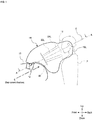
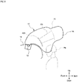
- FIG. 1 is a side view illustrating the deployed state of an airbag 14 of an occupant airbag device according to examples of the present invention.
- FIG. 2 is a schematic view corresponding to the cross section along A-A line in FIG. 1 and illustrating a configuration of tethers constituting the airbag 14, wherein the tethers are illustrated spaced at their connections in order to clearly distinguish each member.
- FIG. 3 is a schematic view corresponding to the cross section along line A-A in FIG. 1 similarly to FIG. 2 and illustrating the size, shape, locations of connections, and the like of panels and the tethers that constitute the airbag 14. In FIG. 3 , white circles indicate stitching locations (connections).
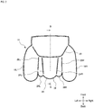
- FIG. 4 is a front view illustrating the deployed state of the airbag 14 and illustrates the state viewed from the occupant side.
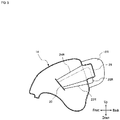
- FIG. 5 is a view corresponding to the cross-section along line B-B in FIG. 2 and illustrating the deployed shape of the airbag 14.
- the airbag device is housed in the instrument panel 10 of a vehicle in order to protect an occupant P in a passenger seat, and includes an inflator 12 for generating inflation gas along with an airbag 14 that inflates and deploys toward the occupant P side via gas released from the inflator 12.
- the airbag 14 includes a front protection part 16 located in front of the occupant P when deployed and a pair of side protruding parts 18L, 18R located on the sides of the front protection part 16 in the vehicle width direction and protruding further toward the occupant P side than the front protection part 16 (see FIG. 2 ).
- a cross tether 20 extending in the direction intersecting the deployment direction E of the airbag 14 and connected to the inner surface of the airbag 14 along with a pair of first front-rear tethers 22L, 22R connected to the cross tether 20 at the front ends thereof and connected to the front protection part 16 at the rear ends thereof are provided inside the airbag 14 (see FIG. 2 , FIG. 3 ).
- the longitudinal direction of the cross tether 20 is preferably a direction orthogonal to the deployment direction E of the airbag 14.
- connections between the rear ends of the first front-rear tethers 22L, 22R and the front protection part 16 are located at boundaries between the front protection part 16 and the side protruding parts 18L, 18R.
- a pair of second front-rear tethers 24L, 24R are provided inside in the vehicle width direction of the pair of first front-rear tethers 22L, 22R, with the front ends of the second front-rear tethers 24L, 24R connected to the cross tether 20, while the rear ends are connected to the front protection part 16.
- a pair of left and right intermediate protruding parts 26L, 26R protruding toward the occupant P side are formed between the first front-rear tethers 22L, 22R and the second front-rear tethers 24L, 24R.
- a central protruding part 28 protruding toward the occupant P side is formed between the pair of second front-rear tethers 24L, 24R.
- the central protruding part 28 protrudes further toward the occupant P side than the intermediate protruding parts 26L, 26R.
- the curvature radius (r1) of the occupant P side of the intermediate protruding parts 26L, 26R is smaller than the curvature radius (r2) of the occupant P side of the central protruding part 28, while the curvature radius (R) of the occupant P side of the side protruding parts 18L, 18R is greater than the curvature radius (r2) of the central protruding part 28.
- the distance d1 between the first front-rear tethers 22L, 22R and the second front-rear tethers 24L, 24R is smaller than the distance d2 between the pair of second front-rear tethers 24L, 24R.
- optimal curvature radii as described above can be set.
- connections between the cross tether 20 and the pair of first front-rear tethers 22L, 22R are configured so as to move further in the occupant direction by a predetermined distance (for example, 125 mm) than the straight line connecting portions at which the both ends of the cross tether 20 are connected to the inner surface of the airbag when the airbag 14 deploys.
- a predetermined distance for example, 125 mm
- FIG. 3 illustrate the state in which the airbag 14 deploys and pressure is applied in the front-rear direction, that is, the state in which the tension of the first front-rear tethers 22L, 22R and the second front-rear tethers 24L, 24R is maximized, and when the inflation gas subsequently spreads throughout the entire airbag 14, pressure is applied in the left-right direction, such that the shape of the airbag 14 extends in the left-right direction (see FIG. 10(B) ).
- the angle ⁇ between the direction in which the first front-rear tethers 22L, 22R extend and the direction in which the cross tether 20 extends from the connections between the cross tether 20 and the first front-rear tethers 22L, 22R toward the connections with the inner surface of the air bag 14 is less than or equal to 45°, more preferably 20 to 40°.
- the angle ⁇ as described above can be matched with the angle at which the occupant approaches in the event of an oblique collision, and by optimally setting this angle ⁇ , the range (margin) in which the airbag expands in the width direction can be ensured to be large when the occupant obliquely approaches the front protection part (and the side protruding parts), improving occupant restraining performance.
- FIG. 6 is a plan view illustrating the shapes of the panels constituting the airbag 14 according to this example, wherein (A) ad (B) are side panels 50R, 50L, while (C) is a front panel 54.
- FIG. 7 is a plan view illustrating a portion of the front panel 54 and illustrates the connection locations with the rear ends of the first and second front-rear tethers 22L, 22R, 24L, 24R.
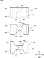
- FIGS. 8(A), (B), and (C) are plan views illustrating the shape variation of the cross tether 20.
- the airbag 14 is formed of two side panels 50L, 50R and one center panel 54.
- the side panels 50L, 50R are panels of the same shape located on both the left and right sides when viewed from the occupant P side and include arc-shaped curved portions 52L, 52R that form the side protruding parts 18L, 18R.
- the front panel 54 includes elliptical or generally circular regions 58L, 58R forming the front protection part 16 of the airbag 14, along with a band-like region 60.
- the arc-shaped curved portions 58L, 58R of the front panel 54 and the curved portions 52L, 52R of the side panels 50L, 50R are connected by stitching, with the other edges of the side panels 50L, 50R connected to both edges of the band-like region 60 of the front panel 54 by stitching.
- the connections (stitching locations) of the first front-rear tethers 22L, 22R with the front protection part 16 of the front panel 54 are 62L and 62R
- the connections (stitching locations) of the second front-rear tethers 24L, 24R are 64L and 64R.
- all of the connections 62L, 62R, 64L, 64R are arranged in parallel and are bilaterally symmetric, these connections do not need to be perfectly parallel and may be disposed or shaped so as to be wider at the upper or lower ends, such as in an inverted V shape.
- connections 62L, 62R with the first front-rear tethers 22L, 22R be disposed offset downward from the connections 64L, 64R with the second front-rear tethers 24L, 24R.
- various variations can be employed in the shape of the cross tether 20, with, for example, a simple rectangular-shaped cross tether 120 as illustrated in (A) and "H"-shaped cross tethers 220, 320 as illustrated in (B) and (C) capable of being employed.
- a simple rectangular-shaped cross tether 120 as illustrated in (A)
- "H"-shaped cross tethers 220, 320 as illustrated in (B) and (C) capable of being employed.
- the shapes of the cross tether 20, 120, 220, 320 illustrated in FIG. 8 are viewed from the occupant side in the extending direction of the first front-rear tethers 22L, 22R (or in the deployment direction E of the airbag).
- both ends 140L, 140R in the longitudinal direction are stitched to the inner surface of the airbag 14 (the side panels 50L, 50R), the front ends of the first front-rear tethers 22L, 22R are stitched to regions 122L, 122R, and the front ends of the second front-rear tethers 24L, 24R are stitched to regions 124L, 124R.
- both ends 240L, 240R in the longitudinal direction are stitched to the inner surface of the airbag 14 (the side panels 50L, 50R), the front ends of the first front-rear tethers 22L, 22R are stitched to regions 222L, 222R, and the front ends of the second front-rear tethers 24L, 24R are stitched to regions 224L, 224R.
- both ends 340L, 340R in the longitudinal direction are stitched to the inner surface of the airbag 14 (the side panels 50L, 50R), the front ends of the first front-rear tethers 22L, 22R are stitched to regions 322L, 322R, and the front ends of the second front-rear tethers 24L, 24R are stitched to regions 324L, 324R.
- connections 122L, 122R, 222L, 222R, 324L, 324R with the first front-rear tethers 22L, 22R are disposed slightly offset downward relative to the connections 124L, 124R, 224L, 224R, 324L, 324R with the second front-rear tethers 24L, 24R.
- FIG. 9 is a side view illustrating the deployed state of the occupant airbag device according to another example of the present invention and illustrates the positional relationship between the occupant P0 out of position (OOP) and the cross tether 420.
- the cross tether 420 is disposed at a location away from the head of the occupant P0 in OOP, for example, in front of the head of the occupant P0, and is disposed at a location spaced upward.
- the cross tether 420 is disposed so as to cover a portion of the instrument panel 10 when the inside of the airbag 14 deployed is viewed from the occupant side in the extending direction of the first and second front-rear tethers 22L, 22R, 24L, 24R. Furthermore, the cross tether 420 is configured so as to be convex toward the occupant P0 side when the inside of the airbag 14 is viewed from the side ( FIG. 9 ). Note that the extending direction of the first and second front-rear tethers can generally be matched with the deployment direction E of the airbag.
- FIG. 10 is a schematic view illustrating the deployed state of the airbag 14 and corresponds to the cross section along A-A line in FIG. 1 .
- (A) illustrates the initial stage of deployment
- (B) illustrates the deployment behavior of the airbag 14 when the occupant P approaches the airbag 14 from the front after the state of (A)
- FIG. 11 illustrates the deployment (deformation) behavior of the airbag 14 when the occupant P approaches the airbag 14 in a diagonal direction (oblique direction).
- inflation gas causes tension in the front-rear direction (deployment direction) to be applied to the first and second front-rear tethers 22L, 22R, 24L, 24R, and the front protection part 16 is attracted toward the vehicle front (the inflator side) at the connections with the first and second front-rear tethers 22L, 22R, 24L, 24R.
- This causes the connections with the first and second front-rear tethers 22L, 22R, 24L, 24R to be recessed when viewed from the occupant P side, with protrusions 26L, 26R, 28 formed between the recessed portions.
- These protrusions 26L, 26R, 28 can soften the surface of the front protection part 16 and gently receive the head of the occupant P, consequently mitigating the impact on the head of the occupant and preventing the turning of the head of the occupant.
- the tension in the front-rear direction of the first and second front-rear tethers 22L, 22R, 24L, 24R decreases, while the tension of the front protection part 16 increases.
- the front ends of the first and second front-rear tethers 22L, 22R, 24L, 24R are connected to the cross tether 20
- the front-rear tethers are drawn frontward by the cross tether while the airbag 14 is deploying in the left-right width direction and a time difference occurs until the protrusions 26L, 26R, 28 fully extend in the width direction, extending the time to maintain the shapes of the protrusions 26L, 26R, 28, although in a short period of time.
- the cross tether 20 that has moved in the occupant P direction as illustrated in FIG. 10(A) subsequently exhibits a behavior of returning frontward as a reaction, as illustrated in FIG. 10(B) . Consequently, while the airbag 14 is deploying in the left-right width direction, a long distance can be ensured for the first and second front-rear tethers 22L, 22R, 24L, 24R to be drawn frontward by the cross tether 20, enabling further lengthening of the time in which the shapes of the protrusions formed between the front-rear tethers are maintained.
- FIG. 10(B) illustrates the state in which the occupant P approaches the airbag 14 (the front protection part 16) from the front, for the case in which the occupant P approaches the airbag 14 in a diagonal direction (oblique direction), the deployment (deformation) behavior of the airbag 14 is as illustrated in FIG. 11 .
- the angle ⁇ formed by the first front-rear tethers 22L, 22R and the front portion of the cross tether is set to 45° or less, as also illustrated in FIG. 3 , when the occupant P approaches the front protection part 16 (and the side protruding parts 18L, 18R), the range (margin) in which the airbag 14 extends in the width direction can assuredly be made large.
- the first front-rear tethers 22L, 22R located on the outer side are offset further downward than the second front-rear tethers 24L, 24R located on the inner side, such that the intermediate protruding parts 26L, 26R are formed further downward than the central protruding part 28. Consequently, when the head of the occupant P approaches the front protection part 16 in an oblique direction and the head of the occupant P slides from the central protruding part 28 toward the side protruding part 18L, the head of the occupant P can be gently received by the intermediate protruding part 26L present further downward than the central protruding part 28.
- FIG. 11 illustrates the case in which the occupant P approaches in an obliquely left front direction, it goes without saying that the same applies to the case of approaching in a right front direction.
Landscapes
- Engineering & Computer Science (AREA)
- Mechanical Engineering (AREA)
- Physics & Mathematics (AREA)
- Fluid Mechanics (AREA)
- Air Bags (AREA)
Abstract
Description
- The present invention relates to an airbag device for protecting an occupant riding in a passenger seat of a vehicle.
- The provision of a vehicle with one or more kinds of airbags in order to protect an occupant in the event of a vehicle accident is well known. There are various forms of airbags, including, for example, a so-called driver airbag that deploys from the vicinity of the center of the steering wheel of an automobile in order to protect a driver, an occupant airbag that deploys from the instrument panel in order to protect an occupant in a passenger seat, a curtain airbag that deploys downward inside a window of the automobile in order to protect the occupant in the event of an impact in the vehicle lateral direction or an overturn or rollover accident, and a side airbag that deploys from the side of the seat in order to protect the occupant in the event of an impact in the vehicle lateral direction. The present invention relates to an airbag device for a passenger seat.
- Incidentally, in the event of a so-called oblique collision in which an impact is exerted on a vehicle from the diagonal front direction, an occupant may approach (contact) a deployed airbag at an irregular angle, causing the head of the occupant to turn. A structure has been proposed that prevents the turning of the head of an occupant in order to prevent an increase in the injury value due to the turning of the head of the occupant.
- For example, in the airbag device described in the following Patent Document 1, a portion that swells out toward the occupant side is provided on both the left and right sides of an airbag to prevent the head of an occupant from turning. However, the device described in Patent Document 1 may potentially not be able to sufficiently prevent the head of an occupant from turning.
- Patent Document 1:
Japanese Unexamined Patent Application Publication No. 2013-14176 - The present invention has been created in view of the above circumstances, and an object thereof is to provide an airbag device that can effectively prevent the turning of the head of an occupant riding in a passenger seat of a vehicle.
- While the means for solving the abovementioned problem is described below, in the specification, claims, and drawings of the present application, "front" refers to the front (in the traveling direction) of a vehicle, "rear" refers to the rear (opposite the traveling direction) of the vehicle, "right" refers to the right side in the traveling direction, "left" refers to the left side in the traveling direction, and "vehicle width direction" refers to the left-right direction.
- In order to solve the abovementioned problem, the present invention is an airbag device that is housed in the instrument panel of a vehicle in order to protect an occupant in a passenger seat and includes an inflator for generating inflation gas, and an airbag that inflates and deploys toward the occupant side via gas released from the inflator. The airbag has a front protection part located in front of the occupant when deployed and a pair of side protruding parts located on the sides of the front protection part in the vehicle width direction and protruding further toward the occupant side than the front protection part. Furthermore, a cross tether extending in the direction intersecting the deployment direction of the airbag and connected to the inner surface of the airbag along with a pair of first front-rear tethers connected to the cross tether at the front ends thereof and connected to the front protection part at the rear ends thereof are provided inside the airbag. Here, the "direction intersecting" means the direction that is not parallel and can be the direction generally close to vertical.
- As described above, in the present invention, a structure is employed that connects the front-rear tethers to the cross tether; therefore, tension is applied to the front-rear tethers by inflation gas when the airbag deploys, while the front protection part is attracted toward the vehicle front (inflator side) at the connections with the front-rear tethers. This causes the connections with the front-rear tethers to be recessed when viewed from the occupant side, with a protrusion formed between the recessed portions. This protrusion can soften the surface of the front protection part and gently receive the head of the occupant, consequently mitigating the impact on the head of the occupant and preventing the turning of the head of the occupant. Thereafter, when the inflation gas spreads throughout the entire airbag, the tension in the front-rear direction of the front-rear tethers decreases, while the tension of the front protection part increases. At this time, since the front-rear tethers are connected to the cross tether, the front-rear tethers are drawn frontward by the cross tether and a time difference occurs until the protrusion formed between the front-rear tethers fully extends in the width direction, extending the time to maintain the shape of the protrusion, although in a short period of time. In other words, compared to the case in which the front ends of the front-rear tethers are connected directly to the inner surface of the airbag, a slight time delay occurs until the tension of the front protection part reaches the maximum after the tension of the front-rear tethers has decreased, extending the time for the front protection part to maintain a flexible state.
- Connections between the rear end of the first front-rear tethers and the front protection part may be structured so as to be located at the boundaries between the front protection part and the side protruding parts. This also causes the airbag (the front protection part) to be pulled frontward by the first front-rear tethers, allowing the side protruding parts to clearly protrude relative to the front protection part.
- The portion between connections of the cross tether with the pair of first front-rear tethers may be configured so as to move further in the occupant direction by a predetermined distance than a straight line connecting the portions at which the both ends of the cross tether are connected to the inner surface of the airbag when the airbag deploys. The cross tether that has moved in the occupant direction during the deployment of the airbag subsequently exhibits a behavior of returning frontward as a reaction. Consequently, while the airbag is deploying in the left-right width direction, a long distance can be ensured for the front-rear tethers to be drawn frontward by the cross tether, enabling further lengthening of the time in which the shape of the protrusion formed between the front-rear tethers is maintained.
- In a state of maximum tension of the first front-rear tethers, the angle θ between the direction in which the first front-rear tethers extend and the direction in which the cross tether extends from the connections between the cross tether and the first front-rear tethers toward the connections with the inner surface of the air bag can be configured so as to be less than or equal to 45°. Specifically, the angle θ is preferably 20 to 40°.
- The angle θ as described above can be matched with the angle in the event of an oblique collision (the angle at which the occupant approaches the airbag), and by optimally setting this angle θ, the range (margin) in which the airbag extends in the width direction can be ensured to be large when the occupant obliquely approaches the front protection part (and the side protruding parts).
- The cross tether can be disposed so as to cover a portion of the instrument panel when the inside of the airbag deployed is viewed from the occupant side in the extending direction of the first front-rear tethers. Furthermore, the cross tether can be configured so as to be convex toward the occupant side when the inside of the airbag deployed is viewed from the side.
- The cross tether can be formed into a letter H shape with the vehicle width direction as the lateral direction, or can be formed into a rectangular shape when viewed from the occupant side in the extending direction of the first front-rear tethers. By devising the shape of the cross tether, it is possible to cause the cross tether to function as a diffuser or a flow straightening member for regulating the flow of inflation gas.
- It is preferable to employ a configuration involving providing a pair of second front-rear tethers inside in the vehicle width direction of the pair of first front-rear tethers, connecting the front ends of the second front-rear tethers to the cross tether, and connecting the rear ends thereof to the front protection part. Furthermore, the front protection part located between the pair of side protruding parts can be configured such that a pair of left and right intermediate protruding parts protruding toward the occupant side are formed between the first front-rear tethers and the second front-rear tethers, with a central protruding part protruding toward the occupant side formed between the pair of second front-rear tethers.
- As described above, by providing a pair of second front-rear tethers in addition to the pair of first front-rear tethers, a plurality (three) of protrusions having a small curvature radius are formed in the front protection part, allowing the flexibility (cushioning) of the front protection part to be further improved.
- Note that the central protruding part can be structured so as to protrude further toward the occupant side than the intermediate protruding parts.
- The curvature radius (r1) of the occupant side of the intermediate protruding parts can be configured so as to be smaller than the curvature radius (r2) of the occupant side of the central protruding part, while the curvature radius (R) of the occupant side of the side protruding parts can be configured so as to be greater than the curvature radius (r2) of the occupant side of the central protruding part.
- By making the curvature radius (r1) of the intermediate protruding parts small, the flexibility (cushioning) of the boundary portions between the front protection part and the side protruding parts increases, allowing the head of the occupant to be gently received when the head moves (slides) toward the side protruding parts in an oblique direction from the front protection part.
- On the front protection part, the distance between the first front-rear tethers and the second front-rear tethers may be smaller than the distance between the pair of second front-rear tethers. Furthermore, the first front-rear tethers may be shorter than the second front-rear tethers. With such settings, it is possible to achieve the optimal curvature radii as described above by a relatively simple method.
- The connections of the front protection part with the pair of first front-rear tethers can be disposed offset in the vertical direction from the connections thereof with the pair of second front-rear tethers. For example, the connections of the front protection part with the pair of first front-rear tethers can be disposed offset downward from the connections thereof with the pair of second front-rear tethers.
- Similarly, on the cross tether, connections with the pair of first front-rear tethers and connections with the pair of second front-rear tethers can be disposed offset from each other in the vertical direction. For example, on the cross tether, the connections with the pair of first front-rear tethers can be disposed offset downward from the connections with the pair of second front-rear tethers.
- When the head of the occupant approaches the front protection part from an oblique direction, a head with a large weight typically moves downward (obliquely downward). Thus, for the case in which the first front-rear tethers located on the outer sides are shifted downward, when the head of the occupant slides from the central protruding part toward the side protruding parts, the head of the occupant can surely and gently be received by the intermediate protruding parts formed by the second front-rear tethers located further downward than the first front-rear tethers.
-
-
FIG. 1 is a side view illustrating the deployed state of an occupant airbag device according to the present invention. -
FIG. 2 is a schematic view (cross-sectional view) corresponding to the cross section along line A-A inFIG. 1 and illustrating a configuration of panels and tethers constituting the airbag, wherein the panels and the tethers are spaced from each other at their connections for purpose of convenience. -
FIG. 3 is a schematic view (cross-sectional view) corresponding to the cross section along line A-A inFIG. 1 similarly toFIG. 2 and illustrating the size, shape, locations of connections, and the like of the panels and the tethers constituting the airbag, wherein the locations of connections and the like between the panels and the tethers are illustrated as circles for purpose of convenience. -
FIG. 4 is a front view illustrating the deployed state of the occupant airbag device according to the present invention and illustrates the state viewed from the occupant side. -
FIG. 5 is a cross-sectional view corresponding to the cross section along line B-B inFIG. 2 and illustrating the deployed shape of the airbag. -
FIG. 6 is a plan view illustrating the shapes of the panels constituting the airbag according to the present invention, wherein (A) and (B) are side panels, while (C) is a front panel. -
FIG. 7 is a plan view illustrating a portion of the front panel constituting the airbag according to the present invention, wherein the connection locations with the front-rear tethers are indicated by broken lines. -
FIGS. 8(A), (B), and (C) are plan views illustrating examples of the cross tether connected to the inside of the airbag according to the present invention. -
FIG. 9 is a side view illustrating the deployed state of the occupant airbag device according to another example of the present invention and illustrates the positional relationship between an occupant located in OOP and the cross tether. -
FIG. 10 is a schematic view illustrating the deployed state of the occupant airbag device according to the present invention and corresponds to the cross section along line A-A inFIG. 1 . InFIG. 10, (A) illustrates the initial stage of deployment, while(B) illustrates the deployment behavior of the airbag when the occupant approaches the airbag from the front after the state of(A) . -
FIG. 11 is a schematic view illustrating the deployed state of the occupant airbag device according to the present invention and corresponding to the cross section along line A-A inFIG. 1 and illustrates the deployment (deformation) behavior of the airbag when the occupant approaches the airbag in a diagonal direction (oblique direction). - Occupant airbag devices according to examples of the present invention are described in detail below based on the accompanying drawings. Note that in the examples, while an occupant P is based on an experimental dummy, the same functions will be achieved with an actual occupant.
-
FIG. 1 is a side view illustrating the deployed state of anairbag 14 of an occupant airbag device according to examples of the present invention.FIG. 2 is a schematic view corresponding to the cross section along A-A line inFIG. 1 and illustrating a configuration of tethers constituting theairbag 14, wherein the tethers are illustrated spaced at their connections in order to clearly distinguish each member.FIG. 3 is a schematic view corresponding to the cross section along line A-A inFIG. 1 similarly toFIG. 2 and illustrating the size, shape, locations of connections, and the like of panels and the tethers that constitute theairbag 14. InFIG. 3 , white circles indicate stitching locations (connections).FIG. 4 is a front view illustrating the deployed state of theairbag 14 and illustrates the state viewed from the occupant side.FIG. 5 is a view corresponding to the cross-section along line B-B inFIG. 2 and illustrating the deployed shape of theairbag 14. - As illustrated in
FIG. 1 , the airbag device according to examples of the present invention is housed in theinstrument panel 10 of a vehicle in order to protect an occupant P in a passenger seat, and includes an inflator 12 for generating inflation gas along with anairbag 14 that inflates and deploys toward the occupant P side via gas released from theinflator 12. - The
airbag 14 includes afront protection part 16 located in front of the occupant P when deployed and a pair ofside protruding parts front protection part 16 in the vehicle width direction and protruding further toward the occupant P side than the front protection part 16 (seeFIG. 2 ). - A
cross tether 20 extending in the direction intersecting the deployment direction E of theairbag 14 and connected to the inner surface of theairbag 14 along with a pair of first front-rear tethers cross tether 20 at the front ends thereof and connected to thefront protection part 16 at the rear ends thereof are provided inside the airbag 14 (seeFIG. 2 ,FIG. 3 ). The longitudinal direction of thecross tether 20 is preferably a direction orthogonal to the deployment direction E of theairbag 14. - As clearly illustrated in
FIG. 3 , connections between the rear ends of the first front-rear tethers front protection part 16 are located at boundaries between thefront protection part 16 and theside protruding parts rear tethers rear tethers rear tethers cross tether 20, while the rear ends are connected to thefront protection part 16. - Furthermore, on the surface of the
front protection part 16, a pair of left and right intermediate protrudingparts rear tethers rear tethers part 28 protruding toward the occupant P side is formed between the pair of second front-rear tethers part 28 protrudes further toward the occupant P side than the intermediate protrudingparts - Furthermore, as illustrated in
FIG. 3 , the curvature radius (r1) of the occupant P side of the intermediate protrudingparts part 28, while the curvature radius (R) of the occupant P side of theside protruding parts part 28. - On the
front protection part 16, the distance d1 between the first front-rear tethers rear tethers rear tethers rear tethers rear tethers front protection part 16, optimal curvature radii as described above can be set. - As illustrated in
FIG. 2 andFIG. 3 , connections between thecross tether 20 and the pair of first front-rear tethers cross tether 20 are connected to the inner surface of the airbag when theairbag 14 deploys. Note thatFIG. 2 andFIG. 3 illustrate the state in which theairbag 14 deploys and pressure is applied in the front-rear direction, that is, the state in which the tension of the first front-rear tethers rear tethers entire airbag 14, pressure is applied in the left-right direction, such that the shape of theairbag 14 extends in the left-right direction (seeFIG. 10(B) ). - Referring again to
FIG. 3 , in the state of maximum tension of the first front-rear tethers rear tethers cross tether 20 extends from the connections between thecross tether 20 and the first front-rear tethers air bag 14 is less than or equal to 45°, more preferably 20 to 40°. The angle θ as described above can be matched with the angle at which the occupant approaches in the event of an oblique collision, and by optimally setting this angle θ, the range (margin) in which the airbag expands in the width direction can be ensured to be large when the occupant obliquely approaches the front protection part (and the side protruding parts), improving occupant restraining performance. -
FIG. 6 is a plan view illustrating the shapes of the panels constituting theairbag 14 according to this example, wherein (A) ad (B) areside panels front panel 54.FIG. 7 is a plan view illustrating a portion of thefront panel 54 and illustrates the connection locations with the rear ends of the first and second front-rear tethers FIGS. 8(A), (B), and (C) are plan views illustrating the shape variation of thecross tether 20. - As illustrated in
FIG. 6 , theairbag 14 according to this example is formed of twoside panels center panel 54. Theside panels curved portions side protruding parts front panel 54 includes elliptical or generallycircular regions front protection part 16 of theairbag 14, along with a band-like region 60. The arc-shapedcurved portions front panel 54 and thecurved portions side panels side panels like region 60 of thefront panel 54 by stitching. - As illustrated in
FIG. 7 , the connections (stitching locations) of the first front-rear tethers front protection part 16 of thefront panel 54 are 62L and 62R, while the connections (stitching locations) of the second front-rear tethers connections - In
FIG. 7 , it is important that theconnections rear tethers connections rear tethers - As illustrated in
FIG. 8 , various variations can be employed in the shape of thecross tether 20, with, for example, a simple rectangular-shapedcross tether 120 as illustrated in (A) and "H"-shaped cross tethers 220, 320 as illustrated in (B) and (C) capable of being employed. Note that the shapes of thecross tether FIG. 8 are viewed from the occupant side in the extending direction of the first front-rear tethers - In the
cross tether 120 illustrated inFIG. 8(A) , both ends 140L, 140R in the longitudinal direction are stitched to the inner surface of the airbag 14 (theside panels rear tethers regions rear tethers regions - In the
cross tether 220 illustrated inFIG. 8(B) , both ends 240L, 240R in the longitudinal direction are stitched to the inner surface of the airbag 14 (theside panels rear tethers regions rear tethers regions - In the
cross tether 320 illustrated inFIG. 8(C) , both ends 340L, 340R in the longitudinal direction are stitched to the inner surface of the airbag 14 (theside panels rear tethers regions rear tethers regions - As illustrated in
FIGS. 8(A) to (C) , similar to the case of the front protection part 16 (FIG. 7 ), on thecross tether connections rear tethers connections rear tethers -
FIG. 9 is a side view illustrating the deployed state of the occupant airbag device according to another example of the present invention and illustrates the positional relationship between the occupant P0 out of position (OOP) and thecross tether 420. In this example, thecross tether 420 is disposed at a location away from the head of the occupant P0 in OOP, for example, in front of the head of the occupant P0, and is disposed at a location spaced upward. - Furthermore, the
cross tether 420 is disposed so as to cover a portion of theinstrument panel 10 when the inside of theairbag 14 deployed is viewed from the occupant side in the extending direction of the first and second front-rear tethers cross tether 420 is configured so as to be convex toward the occupant P0 side when the inside of theairbag 14 is viewed from the side (FIG. 9 ). Note that the extending direction of the first and second front-rear tethers can generally be matched with the deployment direction E of the airbag. - The overall operation of examples of the present invention is described below with reference to
FIG. 10 andFIG. 11 .FIG. 10 is a schematic view illustrating the deployed state of theairbag 14 and corresponds to the cross section along A-A line inFIG. 1 . InFIG. 10, (A) illustrates the initial stage of deployment, while(B) illustrates the deployment behavior of theairbag 14 when the occupant P approaches theairbag 14 from the front after the state of(A) . Meanwhile,FIG. 11 illustrates the deployment (deformation) behavior of theairbag 14 when the occupant P approaches theairbag 14 in a diagonal direction (oblique direction). - When the
airbag 14 deploys due to a vehicle collision, in the initial stage, as illustrated inFIG. 10(A) , inflation gas causes tension in the front-rear direction (deployment direction) to be applied to the first and second front-rear tethers front protection part 16 is attracted toward the vehicle front (the inflator side) at the connections with the first and second front-rear tethers rear tethers protrusions protrusions front protection part 16 and gently receive the head of the occupant P, consequently mitigating the impact on the head of the occupant and preventing the turning of the head of the occupant. - Thereafter, when the inflation gas spreads throughout the
entire airbag 14, the tension in the front-rear direction of the first and second front-rear tethers front protection part 16 increases. At this time, since the front ends of the first and second front-rear tethers cross tether 20, the front-rear tethers are drawn frontward by the cross tether while theairbag 14 is deploying in the left-right width direction and a time difference occurs until theprotrusions protrusions - In particular, the
cross tether 20 that has moved in the occupant P direction as illustrated inFIG. 10(A) subsequently exhibits a behavior of returning frontward as a reaction, as illustrated inFIG. 10(B) . Consequently, while theairbag 14 is deploying in the left-right width direction, a long distance can be ensured for the first and second front-rear tethers cross tether 20, enabling further lengthening of the time in which the shapes of the protrusions formed between the front-rear tethers are maintained. - Note that while
FIG. 10(B) illustrates the state in which the occupant P approaches the airbag 14 (the front protection part 16) from the front, for the case in which the occupant P approaches theairbag 14 in a diagonal direction (oblique direction), the deployment (deformation) behavior of theairbag 14 is as illustrated inFIG. 11 . - In this example, since the angle θ formed by the first front-
rear tethers FIG. 3 , when the occupant P approaches the front protection part 16 (and theside protruding parts airbag 14 extends in the width direction can assuredly be made large. - Furthermore, as also illustrated in
FIG. 4 , the first front-rear tethers rear tethers parts part 28. Consequently, when the head of the occupant P approaches thefront protection part 16 in an oblique direction and the head of the occupant P slides from the central protrudingpart 28 toward theside protruding part 18L, the head of the occupant P can be gently received by the intermediate protrudingpart 26L present further downward than the central protrudingpart 28. Note that whileFIG. 11 illustrates the case in which the occupant P approaches in an obliquely left front direction, it goes without saying that the same applies to the case of approaching in a right front direction. - Examples of the present invention have been described above; however, the present invention is not limited in any way to the examples described above and can be changed as appropriate within the scope of the technical idea as that defined in the claims.
Claims (20)
- An airbag device housed in an instrument panel of a vehicle in order to protect an occupant in a passenger seat, the airbag device comprising:an inflator for generating inflation gas; andan airbag that inflates and deploys toward the occupant side via gas released from the inflator;the airbag having a front protection part located in front of the occupant when deployed and a pair of side protruding parts located on the sides of the front protection part in the vehicle width direction and protruding further to the occupant side than the front protection part; anda cross tether extending in the direction intersecting a deploying direction of the airbag and connected to the inner surface of the airbag and a pair of first front-rear tethers connected to the cross tether at the front ends thereof and connected to the front protection part at rear ends being provided in the inside of the airbag.
- The airbag device according to claim 1, wherein connections between the rear ends of the first front-rear tethers and the front protection part are located at boundaries between the front protection part and the side protruding parts.
- The airbag device according to claim 1 or 2, configured such that, when the air bag deploys, a portion between the connections of the cross tether with the pair of first front-rear tethers moves further in an occupant direction by a predetermined distance than a line connecting portions at which the both ends of the cross tether are connected to the inner surface of the airbag.
- The airbag device according to any one of claims 1 to 3, configured such that, in a state of maximum tension of the first front-rear tethers, an angle θ between a direction in which the first front-rear tethers extend and the direction in which the cross tether extends from the connections between the cross tether and the first front-rear tethers toward connections with the inner surface of the air bag is less than or equal to 45°.
- The airbag device according to claim 4, wherein the angle θ is 20 to 40°.
- The airbag device according to any one of claims 1 to 5, wherein, when the inside of the airbag deployed is viewed from the occupant side in the extending direction of the first front-rear tethers, the cross tether is disposed so as to cover a portion of the instrument panel.
- The airbag device according to claim 6, wherein, when the inside of the airbag deployed is viewed from sideward, the cross tether is convex toward the occupant side.
- The airbag device according to any one of claims 1 to 7, wherein, when viewed from the occupant side in the extending direction of the first front-rear tethers, the cross tether is formed into an alphabetH shape with the vehicle width direction as a lateral direction.
- The airbag device according to any one of claims 1 to 7, wherein, when viewed from the occupant side in the extending direction of the first front-rear tethers, the cross tether is formed into a rectangular shape with the vehicle width direction as a longitudinal direction.
- The airbag device according to any one of claims 1 to 9, wherein:a pair of second front-rear tethers are provided inside in the vehicle width direction of the pair of first front-rear tethers; andfront ends of the second front-rear tethers are connected to the cross tether, and rear ends are connected to the front protection part.
- The airbag device according to claim 10, wherein:in the front protection part located between the pair of side protruding parts, a pair of left and right intermediate protruding parts protruding toward the occupant side are formed between the first front-rear tethers and the second front-rear tethers; anda central protruding part protruding toward the occupant side is formed between the pair of second front-rear tethers.
- The airbag device according to claim 11, wherein the central protruding part protrudes farther toward the occupant side than the intermediate protruding parts.
- The airbag device according to claim 12, configured such that the radius of curvature (r1) of the occupant side of the intermediate protruding parts is smaller than the radius of curvature (r2) of the occupant side of the central protruding part.
- The airbag device according to claim 13, wherein the radius of curvature(R) of the occupant side of the side protruding parts is greater than the radius of curvature (r2) of the occupant side of the central protruding part.
- The airbag device according to any one of claims 10 to 14, wherein, on the front protection part, a distance between the first front-rear tethers and the second front-rear tethers is smaller than a distance between the pair of second front-rear tethers.
- The airbag device according to any one of claims 10 to 15, wherein the first front-rear tethers are set shorter than the second front-rear tethers.
- The airbag device according to any one of claims 10 to 16, wherein the connections of the front protection part with the pair of first front-rear tethers are disposed offset in a vertical direction from the connections thereof with the pair of second front-rear tethers.
- The airbag device according to claim 17, wherein the connections of the front protection part with the pair of first front-rear tethers are disposed offset downward from the connections thereof with the pair of second front-rear tethers.
- The airbag device according to any one of claims 10 to 18, wherein, on the cross tether, connections with the pair of first front-rear tethers and connections with the pair of second front-rear tethers are disposed offset from each other in the vertical direction.
- The airbag device according to claim 19, wherein, on the cross tether, the connections with the pair of first front-rear tethers are disposed offset downward from the connections with the pair of second front-rear tethers.
Applications Claiming Priority (2)
| Application Number | Priority Date | Filing Date | Title |
|---|---|---|---|
| JP2019034939 | 2019-02-27 | ||
| PCT/JP2020/000537 WO2020174892A1 (en) | 2019-02-27 | 2020-01-09 | Airbag device |
Publications (3)
| Publication Number | Publication Date |
|---|---|
| EP3932752A1 true EP3932752A1 (en) | 2022-01-05 |
| EP3932752A4 EP3932752A4 (en) | 2022-06-08 |
| EP3932752B1 EP3932752B1 (en) | 2023-05-03 |
Family
ID=72239297
Family Applications (1)
| Application Number | Title | Priority Date | Filing Date |
|---|---|---|---|
| EP20763629.1A Active EP3932752B1 (en) | 2019-02-27 | 2020-01-09 | Airbag device |
Country Status (6)
| Country | Link |
|---|---|
| US (1) | US11724662B2 (en) |
| EP (1) | EP3932752B1 (en) |
| JP (1) | JP7100188B2 (en) |
| KR (1) | KR102604711B1 (en) |
| CN (1) | CN113365882B (en) |
| WO (1) | WO2020174892A1 (en) |
Families Citing this family (3)
| Publication number | Priority date | Publication date | Assignee | Title |
|---|---|---|---|---|
| US11613225B2 (en) * | 2021-01-20 | 2023-03-28 | Autoliv Asp, Inc. | Airbag device |
| JP7844949B2 (en) * | 2022-03-11 | 2026-04-14 | Joyson Safety Systems Japan合同会社 | Airbags and airbag systems |
| JP7616132B2 (en) * | 2022-03-23 | 2025-01-17 | トヨタ自動車株式会社 | Seat-mounted airbag device |
Family Cites Families (15)
| Publication number | Priority date | Publication date | Assignee | Title |
|---|---|---|---|---|
| JP5327385B2 (en) * | 2010-06-04 | 2013-10-30 | トヨタ自動車株式会社 | Passenger airbag |
| JP5572597B2 (en) | 2011-06-30 | 2014-08-13 | 富士重工業株式会社 | Crew protection device |
| JP5979108B2 (en) * | 2013-09-27 | 2016-08-24 | 豊田合成株式会社 | Airbag |
| DE102015004956A1 (en) | 2015-04-17 | 2016-10-20 | Trw Automotive Gmbh | Frontal gas bag for vehicle occupants and gas bag module |
| KR101755989B1 (en) * | 2016-03-04 | 2017-07-10 | 현대자동차주식회사 | Front airbag for vehicle |
| DE102016119387A1 (en) * | 2016-10-12 | 2018-04-12 | Trw Automotive Gmbh | Front airbag for a vehicle occupant |
| US10293775B2 (en) * | 2016-10-21 | 2019-05-21 | Autoliv Asp, Inc. | Frontal airbag assemblies for reducing rotational velocity of a head of an occupant |
| US20180134244A1 (en) * | 2016-11-11 | 2018-05-17 | Hyundai Motor Company | Front airbag for vehicle |
| JP6760165B2 (en) | 2017-03-22 | 2020-09-23 | トヨタ自動車株式会社 | Passenger airbag device |
| US10343641B2 (en) * | 2017-04-17 | 2019-07-09 | Ford Global Technologies, Llc | Vehicle airbag |
| WO2018198443A1 (en) * | 2017-04-28 | 2018-11-01 | オートリブ ディベロップメント エービー | Air bag device |
| US10919483B2 (en) * | 2017-12-21 | 2021-02-16 | Toyoda Gosei Co., Ltd. | Airbag for steering wheel |
| JP6881364B2 (en) * | 2018-03-16 | 2021-06-02 | 豊田合成株式会社 | Passenger seat airbag device |
| EP3543075B1 (en) * | 2018-03-23 | 2020-11-11 | Autoliv Development AB | Airbag device |
| US11180108B2 (en) * | 2019-03-28 | 2021-11-23 | Toyoda Gosei Co., Ltd. | Preparatory folded form of an airbag |
-
2020
- 2020-01-09 US US17/310,767 patent/US11724662B2/en active Active
- 2020-01-09 EP EP20763629.1A patent/EP3932752B1/en active Active
- 2020-01-09 JP JP2021501675A patent/JP7100188B2/en active Active
- 2020-01-09 WO PCT/JP2020/000537 patent/WO2020174892A1/en not_active Ceased
- 2020-01-09 KR KR1020217030058A patent/KR102604711B1/en active Active
- 2020-01-09 CN CN202080010970.3A patent/CN113365882B/en active Active
Also Published As
| Publication number | Publication date |
|---|---|
| KR20210126741A (en) | 2021-10-20 |
| CN113365882A (en) | 2021-09-07 |
| JPWO2020174892A1 (en) | 2021-10-14 |
| WO2020174892A1 (en) | 2020-09-03 |
| EP3932752B1 (en) | 2023-05-03 |
| EP3932752A4 (en) | 2022-06-08 |
| US11724662B2 (en) | 2023-08-15 |
| JP7100188B2 (en) | 2022-07-12 |
| CN113365882B (en) | 2023-04-18 |
| US20220126778A1 (en) | 2022-04-28 |
| KR102604711B1 (en) | 2023-11-22 |
Similar Documents
| Publication | Publication Date | Title |
|---|---|---|
| KR102781089B1 (en) | Roof curtain airbag for vehicle | |
| CN110293929B (en) | Airbag device | |
| KR102171930B1 (en) | Air Bag Module | |
| EP3932752B1 (en) | Airbag device | |
| CN107499275A (en) | Vehicle airbag installations | |
| US12128848B2 (en) | Roof airbag for vehicle | |
| US11608022B2 (en) | Roof airbag for vehicle | |
| EP4032757A1 (en) | Airbag device | |
| JP6918040B2 (en) | Airbag device | |
| US20180022307A1 (en) | Frontal airbag, frontal airbag module and motor vehicle | |
| CN214492815U (en) | Safety system for a vehicle | |
| KR102589936B1 (en) | Air bag cushion for a vehicle | |
| KR101250413B1 (en) | Unification air-bag module | |
| KR20220098974A (en) | Roof airbag for vehicles | |
| EP2059420B1 (en) | AN AlRBAG | |
| US12337782B2 (en) | Airbag device | |
| KR20220163723A (en) | Seat airbag for vehicle | |
| KR102581851B1 (en) | Passenger seat airbag apparatus for vehicle and folding method thereof | |
| KR102928637B1 (en) | Roof airbag for vehicle | |
| KR20250009213A (en) | Loop airbag | |
| KR20250009214A (en) | Loop airbag | |
| KR20250001326A (en) | Air bag device | |
| JP2006273244A (en) | Airbag device for driver's seat | |
| KR20230126482A (en) | Center side airbag for vehicle | |
| KR20240177591A (en) | Air bag device |
Legal Events
| Date | Code | Title | Description |
|---|---|---|---|
| STAA | Information on the status of an ep patent application or granted ep patent |
Free format text: STATUS: THE INTERNATIONAL PUBLICATION HAS BEEN MADE |
|
| PUAI | Public reference made under article 153(3) epc to a published international application that has entered the european phase |
Free format text: ORIGINAL CODE: 0009012 |
|
| STAA | Information on the status of an ep patent application or granted ep patent |
Free format text: STATUS: REQUEST FOR EXAMINATION WAS MADE |
|
| 17P | Request for examination filed |
Effective date: 20210927 |
|
| AK | Designated contracting states |
Kind code of ref document: A1 Designated state(s): AL AT BE BG CH CY CZ DE DK EE ES FI FR GB GR HR HU IE IS IT LI LT LU LV MC MK MT NL NO PL PT RO RS SE SI SK SM TR |
|
| DAV | Request for validation of the european patent (deleted) | ||
| DAX | Request for extension of the european patent (deleted) | ||
| A4 | Supplementary search report drawn up and despatched |
Effective date: 20220511 |
|
| RIC1 | Information provided on ipc code assigned before grant |
Ipc: B60R 21/2338 20110101ALI20220504BHEP Ipc: B60R 21/205 20110101AFI20220504BHEP |
|
| GRAP | Despatch of communication of intention to grant a patent |
Free format text: ORIGINAL CODE: EPIDOSNIGR1 |
|
| STAA | Information on the status of an ep patent application or granted ep patent |
Free format text: STATUS: GRANT OF PATENT IS INTENDED |
|
| INTG | Intention to grant announced |
Effective date: 20230118 |
|
| GRAS | Grant fee paid |
Free format text: ORIGINAL CODE: EPIDOSNIGR3 |
|
| GRAA | (expected) grant |
Free format text: ORIGINAL CODE: 0009210 |
|
| STAA | Information on the status of an ep patent application or granted ep patent |
Free format text: STATUS: THE PATENT HAS BEEN GRANTED |
|
| AK | Designated contracting states |
Kind code of ref document: B1 Designated state(s): AL AT BE BG CH CY CZ DE DK EE ES FI FR GB GR HR HU IE IS IT LI LT LU LV MC MK MT NL NO PL PT RO RS SE SI SK SM TR |
|
| REG | Reference to a national code |
Ref country code: GB Ref legal event code: FG4D |
|
| REG | Reference to a national code |
Ref country code: AT Ref legal event code: REF Ref document number: 1564328 Country of ref document: AT Kind code of ref document: T Effective date: 20230515 Ref country code: CH Ref legal event code: EP |
|
| REG | Reference to a national code |
Ref country code: DE Ref legal event code: R096 Ref document number: 602020010489 Country of ref document: DE |
|
| REG | Reference to a national code |
Ref country code: IE Ref legal event code: FG4D |
|
| P01 | Opt-out of the competence of the unified patent court (upc) registered |
Effective date: 20230507 |
|
| REG | Reference to a national code |
Ref country code: LT Ref legal event code: MG9D |
|
| REG | Reference to a national code |
Ref country code: NL Ref legal event code: MP Effective date: 20230503 |
|
| REG | Reference to a national code |
Ref country code: AT Ref legal event code: MK05 Ref document number: 1564328 Country of ref document: AT Kind code of ref document: T Effective date: 20230503 |
|
| PG25 | Lapsed in a contracting state [announced via postgrant information from national office to epo] |
Ref country code: SE Free format text: LAPSE BECAUSE OF FAILURE TO SUBMIT A TRANSLATION OF THE DESCRIPTION OR TO PAY THE FEE WITHIN THE PRESCRIBED TIME-LIMIT Effective date: 20230503 Ref country code: PT Free format text: LAPSE BECAUSE OF FAILURE TO SUBMIT A TRANSLATION OF THE DESCRIPTION OR TO PAY THE FEE WITHIN THE PRESCRIBED TIME-LIMIT Effective date: 20230904 Ref country code: NO Free format text: LAPSE BECAUSE OF FAILURE TO SUBMIT A TRANSLATION OF THE DESCRIPTION OR TO PAY THE FEE WITHIN THE PRESCRIBED TIME-LIMIT Effective date: 20230803 Ref country code: NL Free format text: LAPSE BECAUSE OF FAILURE TO SUBMIT A TRANSLATION OF THE DESCRIPTION OR TO PAY THE FEE WITHIN THE PRESCRIBED TIME-LIMIT Effective date: 20230503 Ref country code: ES Free format text: LAPSE BECAUSE OF FAILURE TO SUBMIT A TRANSLATION OF THE DESCRIPTION OR TO PAY THE FEE WITHIN THE PRESCRIBED TIME-LIMIT Effective date: 20230503 Ref country code: AT Free format text: LAPSE BECAUSE OF FAILURE TO SUBMIT A TRANSLATION OF THE DESCRIPTION OR TO PAY THE FEE WITHIN THE PRESCRIBED TIME-LIMIT Effective date: 20230503 |
|
| PG25 | Lapsed in a contracting state [announced via postgrant information from national office to epo] |
Ref country code: RS Free format text: LAPSE BECAUSE OF FAILURE TO SUBMIT A TRANSLATION OF THE DESCRIPTION OR TO PAY THE FEE WITHIN THE PRESCRIBED TIME-LIMIT Effective date: 20230503 Ref country code: PL Free format text: LAPSE BECAUSE OF FAILURE TO SUBMIT A TRANSLATION OF THE DESCRIPTION OR TO PAY THE FEE WITHIN THE PRESCRIBED TIME-LIMIT Effective date: 20230503 Ref country code: LV Free format text: LAPSE BECAUSE OF FAILURE TO SUBMIT A TRANSLATION OF THE DESCRIPTION OR TO PAY THE FEE WITHIN THE PRESCRIBED TIME-LIMIT Effective date: 20230503 Ref country code: LT Free format text: LAPSE BECAUSE OF FAILURE TO SUBMIT A TRANSLATION OF THE DESCRIPTION OR TO PAY THE FEE WITHIN THE PRESCRIBED TIME-LIMIT Effective date: 20230503 Ref country code: IS Free format text: LAPSE BECAUSE OF FAILURE TO SUBMIT A TRANSLATION OF THE DESCRIPTION OR TO PAY THE FEE WITHIN THE PRESCRIBED TIME-LIMIT Effective date: 20230903 Ref country code: HR Free format text: LAPSE BECAUSE OF FAILURE TO SUBMIT A TRANSLATION OF THE DESCRIPTION OR TO PAY THE FEE WITHIN THE PRESCRIBED TIME-LIMIT Effective date: 20230503 Ref country code: GR Free format text: LAPSE BECAUSE OF FAILURE TO SUBMIT A TRANSLATION OF THE DESCRIPTION OR TO PAY THE FEE WITHIN THE PRESCRIBED TIME-LIMIT Effective date: 20230804 |
|
| PG25 | Lapsed in a contracting state [announced via postgrant information from national office to epo] |
Ref country code: FI Free format text: LAPSE BECAUSE OF FAILURE TO SUBMIT A TRANSLATION OF THE DESCRIPTION OR TO PAY THE FEE WITHIN THE PRESCRIBED TIME-LIMIT Effective date: 20230503 |
|
| PG25 | Lapsed in a contracting state [announced via postgrant information from national office to epo] |
Ref country code: SK Free format text: LAPSE BECAUSE OF FAILURE TO SUBMIT A TRANSLATION OF THE DESCRIPTION OR TO PAY THE FEE WITHIN THE PRESCRIBED TIME-LIMIT Effective date: 20230503 |
|
| PG25 | Lapsed in a contracting state [announced via postgrant information from national office to epo] |
Ref country code: SM Free format text: LAPSE BECAUSE OF FAILURE TO SUBMIT A TRANSLATION OF THE DESCRIPTION OR TO PAY THE FEE WITHIN THE PRESCRIBED TIME-LIMIT Effective date: 20230503 Ref country code: SK Free format text: LAPSE BECAUSE OF FAILURE TO SUBMIT A TRANSLATION OF THE DESCRIPTION OR TO PAY THE FEE WITHIN THE PRESCRIBED TIME-LIMIT Effective date: 20230503 Ref country code: RO Free format text: LAPSE BECAUSE OF FAILURE TO SUBMIT A TRANSLATION OF THE DESCRIPTION OR TO PAY THE FEE WITHIN THE PRESCRIBED TIME-LIMIT Effective date: 20230503 Ref country code: EE Free format text: LAPSE BECAUSE OF FAILURE TO SUBMIT A TRANSLATION OF THE DESCRIPTION OR TO PAY THE FEE WITHIN THE PRESCRIBED TIME-LIMIT Effective date: 20230503 Ref country code: DK Free format text: LAPSE BECAUSE OF FAILURE TO SUBMIT A TRANSLATION OF THE DESCRIPTION OR TO PAY THE FEE WITHIN THE PRESCRIBED TIME-LIMIT Effective date: 20230503 Ref country code: CZ Free format text: LAPSE BECAUSE OF FAILURE TO SUBMIT A TRANSLATION OF THE DESCRIPTION OR TO PAY THE FEE WITHIN THE PRESCRIBED TIME-LIMIT Effective date: 20230503 |
|
| REG | Reference to a national code |
Ref country code: DE Ref legal event code: R097 Ref document number: 602020010489 Country of ref document: DE |
|
| PLBE | No opposition filed within time limit |
Free format text: ORIGINAL CODE: 0009261 |
|
| STAA | Information on the status of an ep patent application or granted ep patent |
Free format text: STATUS: NO OPPOSITION FILED WITHIN TIME LIMIT |
|
| 26N | No opposition filed |
Effective date: 20240206 |
|
| PG25 | Lapsed in a contracting state [announced via postgrant information from national office to epo] |
Ref country code: SI Free format text: LAPSE BECAUSE OF FAILURE TO SUBMIT A TRANSLATION OF THE DESCRIPTION OR TO PAY THE FEE WITHIN THE PRESCRIBED TIME-LIMIT Effective date: 20230503 |
|
| PG25 | Lapsed in a contracting state [announced via postgrant information from national office to epo] |
Ref country code: SI Free format text: LAPSE BECAUSE OF FAILURE TO SUBMIT A TRANSLATION OF THE DESCRIPTION OR TO PAY THE FEE WITHIN THE PRESCRIBED TIME-LIMIT Effective date: 20230503 Ref country code: IT Free format text: LAPSE BECAUSE OF FAILURE TO SUBMIT A TRANSLATION OF THE DESCRIPTION OR TO PAY THE FEE WITHIN THE PRESCRIBED TIME-LIMIT Effective date: 20230503 |
|
| PG25 | Lapsed in a contracting state [announced via postgrant information from national office to epo] |
Ref country code: MC Free format text: LAPSE BECAUSE OF FAILURE TO SUBMIT A TRANSLATION OF THE DESCRIPTION OR TO PAY THE FEE WITHIN THE PRESCRIBED TIME-LIMIT Effective date: 20230503 |
|
| PG25 | Lapsed in a contracting state [announced via postgrant information from national office to epo] |
Ref country code: MC Free format text: LAPSE BECAUSE OF FAILURE TO SUBMIT A TRANSLATION OF THE DESCRIPTION OR TO PAY THE FEE WITHIN THE PRESCRIBED TIME-LIMIT Effective date: 20230503 |
|
| REG | Reference to a national code |
Ref country code: CH Ref legal event code: PL |
|
| PG25 | Lapsed in a contracting state [announced via postgrant information from national office to epo] |
Ref country code: LU Free format text: LAPSE BECAUSE OF NON-PAYMENT OF DUE FEES Effective date: 20240109 |
|
| PG25 | Lapsed in a contracting state [announced via postgrant information from national office to epo] |
Ref country code: LU Free format text: LAPSE BECAUSE OF NON-PAYMENT OF DUE FEES Effective date: 20240109 |
|
| PG25 | Lapsed in a contracting state [announced via postgrant information from national office to epo] |
Ref country code: BE Free format text: LAPSE BECAUSE OF NON-PAYMENT OF DUE FEES Effective date: 20240131 |
|
| PG25 | Lapsed in a contracting state [announced via postgrant information from national office to epo] |
Ref country code: CH Free format text: LAPSE BECAUSE OF NON-PAYMENT OF DUE FEES Effective date: 20240131 |
|
| PG25 | Lapsed in a contracting state [announced via postgrant information from national office to epo] |
Ref country code: CH Free format text: LAPSE BECAUSE OF NON-PAYMENT OF DUE FEES Effective date: 20240131 Ref country code: BE Free format text: LAPSE BECAUSE OF NON-PAYMENT OF DUE FEES Effective date: 20240131 |
|
| REG | Reference to a national code |
Ref country code: BE Ref legal event code: MM Effective date: 20240131 |
|
| PG25 | Lapsed in a contracting state [announced via postgrant information from national office to epo] |
Ref country code: BG Free format text: LAPSE BECAUSE OF FAILURE TO SUBMIT A TRANSLATION OF THE DESCRIPTION OR TO PAY THE FEE WITHIN THE PRESCRIBED TIME-LIMIT Effective date: 20230503 |
|
| PG25 | Lapsed in a contracting state [announced via postgrant information from national office to epo] |
Ref country code: BG Free format text: LAPSE BECAUSE OF FAILURE TO SUBMIT A TRANSLATION OF THE DESCRIPTION OR TO PAY THE FEE WITHIN THE PRESCRIBED TIME-LIMIT Effective date: 20230503 |
|
| PG25 | Lapsed in a contracting state [announced via postgrant information from national office to epo] |
Ref country code: IE Free format text: LAPSE BECAUSE OF NON-PAYMENT OF DUE FEES Effective date: 20240109 |
|
| PG25 | Lapsed in a contracting state [announced via postgrant information from national office to epo] |
Ref country code: IE Free format text: LAPSE BECAUSE OF NON-PAYMENT OF DUE FEES Effective date: 20240109 |
|
| PG25 | Lapsed in a contracting state [announced via postgrant information from national office to epo] |
Ref country code: CY Free format text: LAPSE BECAUSE OF FAILURE TO SUBMIT A TRANSLATION OF THE DESCRIPTION OR TO PAY THE FEE WITHIN THE PRESCRIBED TIME-LIMIT; INVALID AB INITIO Effective date: 20200109 |
|
| PG25 | Lapsed in a contracting state [announced via postgrant information from national office to epo] |
Ref country code: HU Free format text: LAPSE BECAUSE OF FAILURE TO SUBMIT A TRANSLATION OF THE DESCRIPTION OR TO PAY THE FEE WITHIN THE PRESCRIBED TIME-LIMIT; INVALID AB INITIO Effective date: 20200109 |
|
| PG25 | Lapsed in a contracting state [announced via postgrant information from national office to epo] |
Ref country code: TR Free format text: LAPSE BECAUSE OF FAILURE TO SUBMIT A TRANSLATION OF THE DESCRIPTION OR TO PAY THE FEE WITHIN THE PRESCRIBED TIME-LIMIT Effective date: 20230503 |
|
| PGFP | Annual fee paid to national office [announced via postgrant information from national office to epo] |
Ref country code: GB Payment date: 20260126 Year of fee payment: 7 |
|
| PGFP | Annual fee paid to national office [announced via postgrant information from national office to epo] |
Ref country code: DE Payment date: 20260127 Year of fee payment: 7 |
|
| PGFP | Annual fee paid to national office [announced via postgrant information from national office to epo] |
Ref country code: FR Payment date: 20260126 Year of fee payment: 7 |