EP3932716A1 - Landwirtschaftliche arbeitsmaschine - Google Patents
Landwirtschaftliche arbeitsmaschine Download PDFInfo
- Publication number
- EP3932716A1 EP3932716A1 EP21176812.2A EP21176812A EP3932716A1 EP 3932716 A1 EP3932716 A1 EP 3932716A1 EP 21176812 A EP21176812 A EP 21176812A EP 3932716 A1 EP3932716 A1 EP 3932716A1
- Authority
- EP
- European Patent Office
- Prior art keywords
- internal combustion
- combustion engine
- work machine
- hybrid module
- transmission device
- Prior art date
- Legal status (The legal status is an assumption and is not a legal conclusion. Google has not performed a legal analysis and makes no representation as to the accuracy of the status listed.)
- Granted
Links
Images

Classifications
-
- B—PERFORMING OPERATIONS; TRANSPORTING
- B60—VEHICLES IN GENERAL
- B60K—ARRANGEMENT OR MOUNTING OF PROPULSION UNITS OR OF TRANSMISSIONS IN VEHICLES; ARRANGEMENT OR MOUNTING OF PLURAL DIVERSE PRIME-MOVERS IN VEHICLES; AUXILIARY DRIVES FOR VEHICLES; INSTRUMENTATION OR DASHBOARDS FOR VEHICLES; ARRANGEMENTS IN CONNECTION WITH COOLING, AIR INTAKE, GAS EXHAUST OR FUEL SUPPLY OF PROPULSION UNITS IN VEHICLES
- B60K6/00—Arrangement or mounting of plural diverse prime-movers for mutual or common propulsion, e.g. hybrid propulsion systems comprising electric motors and internal combustion engines
- B60K6/20—Arrangement or mounting of plural diverse prime-movers for mutual or common propulsion, e.g. hybrid propulsion systems comprising electric motors and internal combustion engines the prime-movers consisting of electric motors and internal combustion engines, e.g. HEVs
- B60K6/42—Arrangement or mounting of plural diverse prime-movers for mutual or common propulsion, e.g. hybrid propulsion systems comprising electric motors and internal combustion engines the prime-movers consisting of electric motors and internal combustion engines, e.g. HEVs characterised by the architecture of the hybrid electric vehicle
- B60K6/48—Parallel type
-
- B—PERFORMING OPERATIONS; TRANSPORTING
- B60—VEHICLES IN GENERAL
- B60K—ARRANGEMENT OR MOUNTING OF PROPULSION UNITS OR OF TRANSMISSIONS IN VEHICLES; ARRANGEMENT OR MOUNTING OF PLURAL DIVERSE PRIME-MOVERS IN VEHICLES; AUXILIARY DRIVES FOR VEHICLES; INSTRUMENTATION OR DASHBOARDS FOR VEHICLES; ARRANGEMENTS IN CONNECTION WITH COOLING, AIR INTAKE, GAS EXHAUST OR FUEL SUPPLY OF PROPULSION UNITS IN VEHICLES
- B60K17/00—Arrangement or mounting of transmissions in vehicles
- B60K17/28—Arrangement or mounting of transmissions in vehicles characterised by arrangement, location, or type of power take-off
-
- B—PERFORMING OPERATIONS; TRANSPORTING
- B60—VEHICLES IN GENERAL
- B60K—ARRANGEMENT OR MOUNTING OF PROPULSION UNITS OR OF TRANSMISSIONS IN VEHICLES; ARRANGEMENT OR MOUNTING OF PLURAL DIVERSE PRIME-MOVERS IN VEHICLES; AUXILIARY DRIVES FOR VEHICLES; INSTRUMENTATION OR DASHBOARDS FOR VEHICLES; ARRANGEMENTS IN CONNECTION WITH COOLING, AIR INTAKE, GAS EXHAUST OR FUEL SUPPLY OF PROPULSION UNITS IN VEHICLES
- B60K6/00—Arrangement or mounting of plural diverse prime-movers for mutual or common propulsion, e.g. hybrid propulsion systems comprising electric motors and internal combustion engines
- B60K6/08—Prime-movers comprising combustion engines and mechanical or fluid energy storing means
- B60K6/12—Prime-movers comprising combustion engines and mechanical or fluid energy storing means by means of a chargeable fluidic accumulator
-
- B—PERFORMING OPERATIONS; TRANSPORTING
- B60—VEHICLES IN GENERAL
- B60K—ARRANGEMENT OR MOUNTING OF PROPULSION UNITS OR OF TRANSMISSIONS IN VEHICLES; ARRANGEMENT OR MOUNTING OF PLURAL DIVERSE PRIME-MOVERS IN VEHICLES; AUXILIARY DRIVES FOR VEHICLES; INSTRUMENTATION OR DASHBOARDS FOR VEHICLES; ARRANGEMENTS IN CONNECTION WITH COOLING, AIR INTAKE, GAS EXHAUST OR FUEL SUPPLY OF PROPULSION UNITS IN VEHICLES
- B60K6/00—Arrangement or mounting of plural diverse prime-movers for mutual or common propulsion, e.g. hybrid propulsion systems comprising electric motors and internal combustion engines
- B60K6/20—Arrangement or mounting of plural diverse prime-movers for mutual or common propulsion, e.g. hybrid propulsion systems comprising electric motors and internal combustion engines the prime-movers consisting of electric motors and internal combustion engines, e.g. HEVs
- B60K6/22—Arrangement or mounting of plural diverse prime-movers for mutual or common propulsion, e.g. hybrid propulsion systems comprising electric motors and internal combustion engines the prime-movers consisting of electric motors and internal combustion engines, e.g. HEVs characterised by apparatus, components or means specially adapted for HEVs
- B60K6/30—Arrangement or mounting of plural diverse prime-movers for mutual or common propulsion, e.g. hybrid propulsion systems comprising electric motors and internal combustion engines the prime-movers consisting of electric motors and internal combustion engines, e.g. HEVs characterised by apparatus, components or means specially adapted for HEVs characterised by chargeable mechanical accumulators, e.g. flywheels
-
- B—PERFORMING OPERATIONS; TRANSPORTING
- B60—VEHICLES IN GENERAL
- B60K—ARRANGEMENT OR MOUNTING OF PROPULSION UNITS OR OF TRANSMISSIONS IN VEHICLES; ARRANGEMENT OR MOUNTING OF PLURAL DIVERSE PRIME-MOVERS IN VEHICLES; AUXILIARY DRIVES FOR VEHICLES; INSTRUMENTATION OR DASHBOARDS FOR VEHICLES; ARRANGEMENTS IN CONNECTION WITH COOLING, AIR INTAKE, GAS EXHAUST OR FUEL SUPPLY OF PROPULSION UNITS IN VEHICLES
- B60K6/00—Arrangement or mounting of plural diverse prime-movers for mutual or common propulsion, e.g. hybrid propulsion systems comprising electric motors and internal combustion engines
- B60K6/20—Arrangement or mounting of plural diverse prime-movers for mutual or common propulsion, e.g. hybrid propulsion systems comprising electric motors and internal combustion engines the prime-movers consisting of electric motors and internal combustion engines, e.g. HEVs
- B60K6/22—Arrangement or mounting of plural diverse prime-movers for mutual or common propulsion, e.g. hybrid propulsion systems comprising electric motors and internal combustion engines the prime-movers consisting of electric motors and internal combustion engines, e.g. HEVs characterised by apparatus, components or means specially adapted for HEVs
- B60K6/38—Arrangement or mounting of plural diverse prime-movers for mutual or common propulsion, e.g. hybrid propulsion systems comprising electric motors and internal combustion engines the prime-movers consisting of electric motors and internal combustion engines, e.g. HEVs characterised by apparatus, components or means specially adapted for HEVs characterised by the driveline clutches
- B60K6/387—Actuated clutches, i.e. clutches engaged or disengaged by electric, hydraulic or mechanical actuating means
-
- B—PERFORMING OPERATIONS; TRANSPORTING
- B60—VEHICLES IN GENERAL
- B60K—ARRANGEMENT OR MOUNTING OF PROPULSION UNITS OR OF TRANSMISSIONS IN VEHICLES; ARRANGEMENT OR MOUNTING OF PLURAL DIVERSE PRIME-MOVERS IN VEHICLES; AUXILIARY DRIVES FOR VEHICLES; INSTRUMENTATION OR DASHBOARDS FOR VEHICLES; ARRANGEMENTS IN CONNECTION WITH COOLING, AIR INTAKE, GAS EXHAUST OR FUEL SUPPLY OF PROPULSION UNITS IN VEHICLES
- B60K6/00—Arrangement or mounting of plural diverse prime-movers for mutual or common propulsion, e.g. hybrid propulsion systems comprising electric motors and internal combustion engines
- B60K6/20—Arrangement or mounting of plural diverse prime-movers for mutual or common propulsion, e.g. hybrid propulsion systems comprising electric motors and internal combustion engines the prime-movers consisting of electric motors and internal combustion engines, e.g. HEVs
- B60K6/22—Arrangement or mounting of plural diverse prime-movers for mutual or common propulsion, e.g. hybrid propulsion systems comprising electric motors and internal combustion engines the prime-movers consisting of electric motors and internal combustion engines, e.g. HEVs characterised by apparatus, components or means specially adapted for HEVs
- B60K6/40—Arrangement or mounting of plural diverse prime-movers for mutual or common propulsion, e.g. hybrid propulsion systems comprising electric motors and internal combustion engines the prime-movers consisting of electric motors and internal combustion engines, e.g. HEVs characterised by apparatus, components or means specially adapted for HEVs characterised by the assembly or relative disposition of components
-
- B—PERFORMING OPERATIONS; TRANSPORTING
- B60—VEHICLES IN GENERAL
- B60K—ARRANGEMENT OR MOUNTING OF PROPULSION UNITS OR OF TRANSMISSIONS IN VEHICLES; ARRANGEMENT OR MOUNTING OF PLURAL DIVERSE PRIME-MOVERS IN VEHICLES; AUXILIARY DRIVES FOR VEHICLES; INSTRUMENTATION OR DASHBOARDS FOR VEHICLES; ARRANGEMENTS IN CONNECTION WITH COOLING, AIR INTAKE, GAS EXHAUST OR FUEL SUPPLY OF PROPULSION UNITS IN VEHICLES
- B60K6/00—Arrangement or mounting of plural diverse prime-movers for mutual or common propulsion, e.g. hybrid propulsion systems comprising electric motors and internal combustion engines
- B60K6/20—Arrangement or mounting of plural diverse prime-movers for mutual or common propulsion, e.g. hybrid propulsion systems comprising electric motors and internal combustion engines the prime-movers consisting of electric motors and internal combustion engines, e.g. HEVs
- B60K6/50—Architecture of the driveline characterised by arrangement or kind of transmission units
- B60K6/52—Driving a plurality of drive axles, e.g. four-wheel drive
-
- B—PERFORMING OPERATIONS; TRANSPORTING
- B60—VEHICLES IN GENERAL
- B60K—ARRANGEMENT OR MOUNTING OF PROPULSION UNITS OR OF TRANSMISSIONS IN VEHICLES; ARRANGEMENT OR MOUNTING OF PLURAL DIVERSE PRIME-MOVERS IN VEHICLES; AUXILIARY DRIVES FOR VEHICLES; INSTRUMENTATION OR DASHBOARDS FOR VEHICLES; ARRANGEMENTS IN CONNECTION WITH COOLING, AIR INTAKE, GAS EXHAUST OR FUEL SUPPLY OF PROPULSION UNITS IN VEHICLES
- B60K17/00—Arrangement or mounting of transmissions in vehicles
- B60K17/34—Arrangement or mounting of transmissions in vehicles for driving both front and rear wheels, e.g. four wheel drive vehicles
- B60K17/348—Arrangement or mounting of transmissions in vehicles for driving both front and rear wheels, e.g. four wheel drive vehicles having differential means for driving one set of wheels, e.g. the front, at one speed and the other set, e.g. the rear, at a different speed
- B60K17/35—Arrangement or mounting of transmissions in vehicles for driving both front and rear wheels, e.g. four wheel drive vehicles having differential means for driving one set of wheels, e.g. the front, at one speed and the other set, e.g. the rear, at a different speed including arrangements for suppressing or influencing the power transfer, e.g. viscous clutches
-
- B—PERFORMING OPERATIONS; TRANSPORTING
- B60—VEHICLES IN GENERAL
- B60K—ARRANGEMENT OR MOUNTING OF PROPULSION UNITS OR OF TRANSMISSIONS IN VEHICLES; ARRANGEMENT OR MOUNTING OF PLURAL DIVERSE PRIME-MOVERS IN VEHICLES; AUXILIARY DRIVES FOR VEHICLES; INSTRUMENTATION OR DASHBOARDS FOR VEHICLES; ARRANGEMENTS IN CONNECTION WITH COOLING, AIR INTAKE, GAS EXHAUST OR FUEL SUPPLY OF PROPULSION UNITS IN VEHICLES
- B60K6/00—Arrangement or mounting of plural diverse prime-movers for mutual or common propulsion, e.g. hybrid propulsion systems comprising electric motors and internal combustion engines
- B60K6/20—Arrangement or mounting of plural diverse prime-movers for mutual or common propulsion, e.g. hybrid propulsion systems comprising electric motors and internal combustion engines the prime-movers consisting of electric motors and internal combustion engines, e.g. HEVs
- B60K6/42—Arrangement or mounting of plural diverse prime-movers for mutual or common propulsion, e.g. hybrid propulsion systems comprising electric motors and internal combustion engines the prime-movers consisting of electric motors and internal combustion engines, e.g. HEVs characterised by the architecture of the hybrid electric vehicle
- B60K6/48—Parallel type
- B60K2006/4825—Electric machine connected or connectable to gearbox input shaft
-
- B—PERFORMING OPERATIONS; TRANSPORTING
- B60—VEHICLES IN GENERAL
- B60K—ARRANGEMENT OR MOUNTING OF PROPULSION UNITS OR OF TRANSMISSIONS IN VEHICLES; ARRANGEMENT OR MOUNTING OF PLURAL DIVERSE PRIME-MOVERS IN VEHICLES; AUXILIARY DRIVES FOR VEHICLES; INSTRUMENTATION OR DASHBOARDS FOR VEHICLES; ARRANGEMENTS IN CONNECTION WITH COOLING, AIR INTAKE, GAS EXHAUST OR FUEL SUPPLY OF PROPULSION UNITS IN VEHICLES
- B60K6/00—Arrangement or mounting of plural diverse prime-movers for mutual or common propulsion, e.g. hybrid propulsion systems comprising electric motors and internal combustion engines
- B60K6/20—Arrangement or mounting of plural diverse prime-movers for mutual or common propulsion, e.g. hybrid propulsion systems comprising electric motors and internal combustion engines the prime-movers consisting of electric motors and internal combustion engines, e.g. HEVs
- B60K6/42—Arrangement or mounting of plural diverse prime-movers for mutual or common propulsion, e.g. hybrid propulsion systems comprising electric motors and internal combustion engines the prime-movers consisting of electric motors and internal combustion engines, e.g. HEVs characterised by the architecture of the hybrid electric vehicle
- B60K6/48—Parallel type
- B60K2006/4833—Step up or reduction gearing driving generator, e.g. to operate generator in most efficient speed range
-
- B—PERFORMING OPERATIONS; TRANSPORTING
- B60—VEHICLES IN GENERAL
- B60K—ARRANGEMENT OR MOUNTING OF PROPULSION UNITS OR OF TRANSMISSIONS IN VEHICLES; ARRANGEMENT OR MOUNTING OF PLURAL DIVERSE PRIME-MOVERS IN VEHICLES; AUXILIARY DRIVES FOR VEHICLES; INSTRUMENTATION OR DASHBOARDS FOR VEHICLES; ARRANGEMENTS IN CONNECTION WITH COOLING, AIR INTAKE, GAS EXHAUST OR FUEL SUPPLY OF PROPULSION UNITS IN VEHICLES
- B60K23/00—Arrangement or mounting of control devices for vehicle transmissions, or parts thereof, not otherwise provided for
- B60K23/08—Arrangement or mounting of control devices for vehicle transmissions, or parts thereof, not otherwise provided for for changing number of driven wheels, for switching from driving one axle to driving two or more axles
- B60K23/0808—Arrangement or mounting of control devices for vehicle transmissions, or parts thereof, not otherwise provided for for changing number of driven wheels, for switching from driving one axle to driving two or more axles for varying torque distribution between driven axles, e.g. by transfer clutch
- B60K2023/0816—Arrangement or mounting of control devices for vehicle transmissions, or parts thereof, not otherwise provided for for changing number of driven wheels, for switching from driving one axle to driving two or more axles for varying torque distribution between driven axles, e.g. by transfer clutch for varying front-rear torque distribution with a central differential
- B60K2023/0825—Arrangement or mounting of control devices for vehicle transmissions, or parts thereof, not otherwise provided for for changing number of driven wheels, for switching from driving one axle to driving two or more axles for varying torque distribution between driven axles, e.g. by transfer clutch for varying front-rear torque distribution with a central differential for adding torque to the front wheels
-
- B—PERFORMING OPERATIONS; TRANSPORTING
- B60—VEHICLES IN GENERAL
- B60K—ARRANGEMENT OR MOUNTING OF PROPULSION UNITS OR OF TRANSMISSIONS IN VEHICLES; ARRANGEMENT OR MOUNTING OF PLURAL DIVERSE PRIME-MOVERS IN VEHICLES; AUXILIARY DRIVES FOR VEHICLES; INSTRUMENTATION OR DASHBOARDS FOR VEHICLES; ARRANGEMENTS IN CONNECTION WITH COOLING, AIR INTAKE, GAS EXHAUST OR FUEL SUPPLY OF PROPULSION UNITS IN VEHICLES
- B60K23/00—Arrangement or mounting of control devices for vehicle transmissions, or parts thereof, not otherwise provided for
- B60K23/08—Arrangement or mounting of control devices for vehicle transmissions, or parts thereof, not otherwise provided for for changing number of driven wheels, for switching from driving one axle to driving two or more axles
- B60K23/0808—Arrangement or mounting of control devices for vehicle transmissions, or parts thereof, not otherwise provided for for changing number of driven wheels, for switching from driving one axle to driving two or more axles for varying torque distribution between driven axles, e.g. by transfer clutch
-
- B—PERFORMING OPERATIONS; TRANSPORTING
- B60—VEHICLES IN GENERAL
- B60Y—INDEXING SCHEME RELATING TO ASPECTS CROSS-CUTTING VEHICLE TECHNOLOGY
- B60Y2200/00—Type of vehicle
- B60Y2200/20—Off-Road Vehicles
- B60Y2200/22—Agricultural vehicles
- B60Y2200/221—Tractors
-
- Y—GENERAL TAGGING OF NEW TECHNOLOGICAL DEVELOPMENTS; GENERAL TAGGING OF CROSS-SECTIONAL TECHNOLOGIES SPANNING OVER SEVERAL SECTIONS OF THE IPC; TECHNICAL SUBJECTS COVERED BY FORMER USPC CROSS-REFERENCE ART COLLECTIONS [XRACs] AND DIGESTS
- Y02—TECHNOLOGIES OR APPLICATIONS FOR MITIGATION OR ADAPTATION AGAINST CLIMATE CHANGE
- Y02T—CLIMATE CHANGE MITIGATION TECHNOLOGIES RELATED TO TRANSPORTATION
- Y02T10/00—Road transport of goods or passengers
- Y02T10/60—Other road transportation technologies with climate change mitigation effect
- Y02T10/62—Hybrid vehicles
Definitions
- the present application relates to an agricultural work machine according to the preamble of claim 1.
- the agricultural work machine which can in particular be formed by a tractor, comprises a front axle and a rear axle, which are each equipped with at least two wheels.
- the wheels can be formed by conventional round wheels, in which case each axle typically interacts with two wheels. It is also conceivable that one of the axles or both axles cooperate with wheels of a chain drive, whereby a respective axle can cooperate for example with four wheels, namely two wheels per side of the axle, with the wheels belonging to one side and assigned to one another with a drive chain cooperate.
- the work machine comprises an internal combustion engine, by means of which an output power can be made available for operating the work machine.
- the internal combustion engine can in particular be formed by a diesel engine.
- the work machine comprises at least one hybrid module, by means of which an output power for operating the work machine can likewise be provided.
- the internal combustion engine and the hybrid module work together so that - for example, to drive the rear wheels - the driven machine can be propelled by means of combined output power from the internal combustion engine and the hybrid module.
- power consumption by the internal combustion engine and the hybrid module for internal consumers such as generators, pumps, compressors and the like is conceivable.
- the hybrid module can in particular be formed by an electric motor or a hydraulic motor. An embodiment as an electric machine or hydraulic machine is also conceivable, which, in addition to a motor function, can also be used in reverse as a generator.
- the work machine also includes a transmission device that is in operative connection both with the internal combustion engine and with the hybrid module.
- the transmission device is designed to receive both the output power of the internal combustion engine and the output power of the hybrid module and to combine the output powers with one another. The combined output power can then be transmitted to the rear axle by means of the transmission device, so that the rear wheels of the work machine arranged on the rear axle can be driven.
- the internal combustion engine of the work machine is arranged in a front area of the same, with preferably at least 50% of the internal weight of the internal combustion engine being diverted into the ground via the front wheels.
- the internal combustion engine is advantageously arranged below an engine hood arranged in the front area, the internal combustion engine typically being positioned directly above the front axle. It is therefore customary for at least 90%, preferably 100%, of the internal weight of the internal combustion engine to be diverted into the ground via the front wheels.
- German patent application DE 10 2018 2018 078 A1 pointed out.
- This describes a work machine that is equipped both with an internal combustion engine and with a hybrid module designed as an electric motor.
- the internal combustion engine and the electric motor can be used together to drive a drive axle and wheels of the work machine belonging to the drive axis and in this way to provide propulsion of the work machine.
- the work machine has a transmission device by means of which the output powers of the internal combustion engine and the electric motor can be summed up and delivered together to the drive axle.
- the present application is therefore based on the object of providing a work machine whose drive train is more efficient than the prior art.
- the work machine according to the invention is characterized in that the hybrid module is arranged in a rear area of the work machine, the Output powers of the internal combustion engine and the hybrid module of the transmission device can be fed separately via separate drive train sections.
- the internal combustion engine and the hybrid module can each be connected to the transmission device by means of their own output shafts or separate output shaft sections of a common main output shaft, the transmission device having at least two inputs for corresponding output shafts or output shaft sections.
- the hybrid module is preferably arranged near the rear axle of the work machine.
- a center of gravity of the hybrid module can be arranged within an imaginary cylinder space spanned by rear wheels designed as round wheels.
- At least 50% of the hybrid module's own weight is diverted into the ground via the rear wheels. More preferably, at least 90%, preferably 100%, of the hybrid module's own weight is diverted into the ground via the rear wheels.
- the work machine according to the invention has many advantages. In particular, it equalizes the provision of a maximum output power from the internal combustion engine and hybrid module in terms of space.
- the internal combustion engine is arranged in the front area of the work machine, which is particularly advantageous from the point of view of mass distribution - especially with regard to any work equipment that can be attached to the work machine at a rear end.
- the internal combustion engine thus typically has a high mass which forms a counterweight to any trailer loads.
- the hybrid module is arranged on the rear axle and can therefore be in spatial proximity to the rear axle as such, to which a substantial proportion of the output power of both the internal combustion engine and the hybrid module should be able to be directed.
- the drive train section extending from the front internal combustion engine to the rear axle can be dimensioned for a lower output compared to the prior art, namely only that of the internal combustion engine, since the output power of the hybrid module is not - as in the prior art - already impacted on the drive train in the front area, but only in the rear area of the work machine.
- the transmission device is arranged spatially between the internal combustion engine and the hybrid module.
- the output power of the internal combustion engine is consequently fed to the transmission device “from the front” and the output power of the hybrid module “from the rear”.
- the arrangement of the transmission device between the internal combustion engine and the hybrid module is particularly simple with regard to the space available on the work machine.
- such a configuration of the work machine according to the invention is particularly advantageous in which the hybrid module is integrated in the rear axle.
- the hybrid module is integrated in the rear axle.
- at least 90%, preferably 100%, of the inherent weight of the hybrid module is diverted into the ground via the rear axle and consequently the rear wheels of the work machine.
- the integration of the hybrid module into the rear axle has the particular advantage that the distance between the hybrid module and the rear axle is minimal, and a distance between the hybrid module and other consumers arranged at the rear end of the work machine is very short, so that at least some of the Output power of the hybrid module only has to be led over a short distance to the respective consumers.
- a flywheel damper which interacts with an output shaft or an output shaft section of the internal combustion engine, is arranged in front of the transmission device when viewed in the direction of the power flow, i.e. upstream of the transmission device.
- the output powers of the internal combustion engine and the hybrid module are dissipated by means of separate output shafts or separate output shaft sections, with the output powers being fed separately to the transmission device in particular.
- the internal combustion engine is assigned a flywheel damper - as is customary in the prior art - which interacts with the output shaft of the internal combustion engine.
- the arrangement of the flywheel damper in front of the transmission device has the advantage that the flywheel damper only has to be dimensioned for the output power of the internal combustion engine, not for a total output power of the internal combustion engine and hybrid module together. This is for sizing of the flywheel damper is of particular advantage, as a result of which the work machine can be constructed more efficiently overall.
- the transmission device Since the output powers of the internal combustion engine and the hybrid module can be combined by means of the transmission device, it is necessary that a drive train section formed downstream of the transmission device, by means of which the combined output power from the transmission device is routed to the rear axle, for the sum of the output powers from the internal combustion engine and the Hybrid module is designed.
- the transmission device is spatially assigned to the rear axle, so that a spatial distance between the transmission device and the rear axle - and therefore a length of the fully loaded drive train section, by means of which the combined output power must be transmitted is as short as possible.
- the transmission device is advantageously assigned to the rear axle in such a way that at least 50%, preferably at least 75%, more preferably at least 85% of the weight of the transmission device is diverted into the ground via the rear wheels of the work machine.
- output shafts and / or output shaft sections of the internal combustion engine and of the hybrid module are arranged coaxially or at right angles to one another.
- the output shafts can advantageously be connected to one another in a torque-transmitting manner, for example by means of a coupling, and in this way form a common main output shaft.
- This embodiment has the particular advantage that an output power provided by the internal combustion engine can be passed on to the rear consumers of the work machine, with the main output shaft running through to the rear area of the work machine in a particularly preferred manner.
- the output shaft of the internal combustion engine is coupled to the output shaft of the hybrid module, the said consumers being connected equally to the main output shaft.
- the consumers can therefore - depending on the setting - be operated either with the sole output power of the internal combustion engine, the sole output power of the hybrid module or a combined output power of the internal combustion engine and hybrid module.
- the main output shaft can interact with at least one consumer, preferably a plurality of consumers, in the rear area of the work machine.
- Such consumers can be, for example, a generator, in particular a high-voltage generator, a hydraulic pump and / or a power take-off shaft.
- the working machine advantageously has at least one generator which is arranged in its rear area and which can in particular be designed as a high-voltage generator.
- a generator is particularly well suited to supplying a socket located in the rear area with electrical power, with line costs and line losses being low due to the short distances between the generator and the socket.
- the same advantage applies to the supply of high-voltage attachments that are connected to the rear of the machine. These can be supplied with electricity particularly efficiently by means of the generator arranged in the rear area.
- Such a configuration of the work machine according to the invention can be particularly advantageous in which a drive shaft of the internal combustion engine interacts with at least one consumer in the front region of the work machine.
- the output shaft interacts with a plurality of consumers.
- This can be, for example, a front power take-off shaft, by means of which external working devices can be coupled to the working machine and in this way can be supplied with an output power.
- at least one pump and / or at least one generator are connected to the output shaft of the internal combustion engine in the front area of the working machine.
- FIG. 1 An embodiment that is in the Figures 1 and 2 is shown, comprises a work machine 1 according to the invention, which is formed here by a tractor.
- the working machine 1 comprises a front axle 2 and a rear axle 3, being arranged on the front axle 2, two round wheels designed as front wheels 7 and two on a rear axle 3 formed as a rotary wheels rear wheels.
- 8 In a front area 9 of the work machine 1 , the work machine 1 has an engine hood 20 , below which there is an internal combustion engine 4 , which is shown in FIG Figure 1 is illustrated by means of a dashed line.
- the internal combustion engine 4 is formed here by a diesel engine.
- the internal combustion engine 4 is assigned to the front axle 2 in such a way that the dead weight of the internal combustion engine 4 is completely diverted via the front axle 2 and the front wheels 7 into a subsurface 30.
- the work machine 2 also includes a hybrid module 5 , which is formed here by an electric motor.
- the hybrid module 5 is assigned to the rear axle 3 , the center of gravity of the hybrid module 5 being located in an imaginary cylinder space spanned by the rear wheels 8.
- the hybrid module 5 is integrated into the rear axle 3 , so that here 100% of the dead weight of the hybrid module 5 is diverted into the ground 30 via the rear wheels 8.
- the hybrid module 5 is therefore assigned to a rear area 10 of the work machine 2 .
- the internal combustion engine 4 interacts with an output shaft 12 assigned to it, by means of which an output power of the working machine 4 can be conducted to downstream consumers.
- the output shaft 12 extends from the internal combustion engine 4 both in the direction of a front end of the work machine 2 and in the direction of a rear end. In this way, both front-side consumers 18 and rear-side consumers 15 can be supplied with a corresponding power by means of the internal combustion engine 4.
- the work machine 1 has, for example, a power take-off shaft 19 , which can be coupled to the output shaft 12 by means of a coupling 25, if necessary.
- the output shaft 12 is in operative connection with further consumers 18 , which are formed here, for example, by a compressor, a fan and a generator.
- a brake 21 by means of which a braking torque can be applied to the output shaft 12 , is also arranged on the output shaft 12 of the internal combustion engine 4.
- the drive shaft 12 also interacts with a flywheel damper 11 . This is arranged on this side of a transmission device 6 , viewed in the direction of the power flow, which interacts with the output shaft 12 .
- the output shaft 12 is fed to the transmission device 6 from the front region 9 of the working machine 1 , the transmission device 6 having a corresponding input.
- the hybrid module 5 for its part also interacts with an output shaft 13 which extends both in the direction of the front area 9 and a rear end of the work machine 1 .
- the transmission device 6 is connected directly to the rear axle 3 , the output shaft 13 of the hybrid module 5 only extending over a short distance from the hybrid module 5 to the transmission device 6 .
- the output shaft 12 of the internal combustion engine 4 runs from the front area 9 to the rear area 10 assigned transmission device 6 by.
- the transmission device 6 is assigned to the rear axle 3 in such a way that its own weight is diverted to at least 75% via the rear axle 3 and consequently the rear wheels 8 into the ground 30 .
- output powers of the internal combustion engine 4 and of the hybrid module 5 are branched off by means of a junction 22 and are supplied to the transmission device 6 in this way.
- This interacts in the area of the rear axle 3 with a differential gear 29 , by means of which the output power is divided between the two rear wheels 8 .
- the transmission device 6 is followed by a further branch 31 , by means of which part of the output power can be fed to the front axle 2 via a clutch 27, if necessary.
- the front axle 2 is also equipped with a differential gear 28 , so that here, too, power can be distributed to the two front wheels 7 .
- the output shafts 12 , 13 do not have to be designed for a sum of the output powers of the internal combustion engine 4 and the hybrid module 5 . This applies in particular to the flywheel damper 11 , which is only subjected to the output power of the internal combustion engine 4.
- further consumers 15 are arranged, which can be supplied by means of the internal combustion engine 4 and the hybrid module 5.
- the consumers are formed here by two hydraulic pumps 16 and a power take-off shaft 17 .
- the output shaft 13 of the hybrid module 12 extends from the hybrid module 5 to a rear end of the working machine 1.
- the output shaft 13 interacts with a pump transfer gear 24 , by means of which one of The output power taken from the output shaft 13 is distributed to the two hydraulic pumps 16.
- a reduction 23 is interposed.
- the output shafts 12 , 13 of the internal combustion engine 4 and of the hybrid module 5 are arranged coaxially or at right angles to one another and are connected to one another.
- the output shafts 12 , 13 form output shaft sections of a main output shaft 14 , by means of which the output power of the work machine 4 and the hybrid module 5 are combined with one another can be.
- the main output shaft 14, which extends from the front area 9 to the rear area 10 at least at times exclusively transmits the output power of the internal combustion engine 4 and the loads 15 are accordingly driven exclusively by the internal combustion engine 4 . It is equally conceivable that the consumers 15 are at least temporarily driven exclusively by means of the hybrid module 5 .
Landscapes
- Engineering & Computer Science (AREA)
- Chemical & Material Sciences (AREA)
- Combustion & Propulsion (AREA)
- Transportation (AREA)
- Mechanical Engineering (AREA)
- Hybrid Electric Vehicles (AREA)
- Arrangement And Driving Of Transmission Devices (AREA)
Abstract
Description
- Die vorliegende Anmeldung betrifft eine landwirtschaftliche Arbeitsmaschine gemäß dem Oberbegriff von Anspruch 1.
- Die landwirtschaftliche Arbeitsmaschine, die insbesondere von einem Traktor gebildet sein kann, umfasst eine Vorderachse und eine Hinterachse, die jeweils mit mindestens zwei Rädern ausgestattet sind. Die Räder können von üblichen Rundrädern gebildet sein, wobei dann typischerweise jede Achse mit zwei Rädern zusammenwirkt. Ebenso ist es denkbar, dass eine der Achsen oder beide Achsen mit Rädern eines Kettenantriebs zusammenwirken, wobei eine jeweilige Achse beispielsweise mit vier Rädern zusammenwirken kann, nämlich zwei Rädern pro Seite der Achse, wobei die zu einer Seite gehörigen, einander zugeordneten Räder mit einer Antriebskette zusammenwirken.
- Ferner umfasst die Arbeitsmaschine eine Verbrennungskraftmaschine, mittels der eine Ausgangsleistung zum Betrieb der Arbeitsmaschine zur Verfügung gestellt werden kann. Die Verbrennungskraftmaschine kann insbesondere von einem Dieselmotor gebildet sein. Ferner umfasst die Arbeitsmaschine mindestens ein Hybridmodul, mittels dessen gleichermaßen eine Ausgangsleistung zum Betrieb der Arbeitsmaschine bereitgestellt werden kann. Die Verbrennungskraftmaschine und das Hybridmodul arbeiten gemeinsam, sodass - beispielsweise zum Antrieb der Hinterräder - ein Vortrieb der Arbeitsmaschine mittels kombinierter Ausgangsleistungen aus der Verbrennungskraftmaschine und dem Hybridmodul bewerkstelligt werden kann. Dasselbe gilt für andere Verbraucher der Arbeitsmaschine wie beispielsweise eine Zapfwelle, mittels der externe Arbeitsmaschinen angetrieben werden können. Ferner ist eine Leistungsaufnahme von der Verbrennungskraftmaschine und dem Hybridmodul für interne Verbraucher denkbar wie beispielsweise Generatoren, Pumpen, Kompressoren und dergleichen. Das Hybridmodul kann insbesondere von einem Elektromotor oder einem Hydromotor gebildet sein. Auch ist eine Ausgestaltung als Elektromaschine oder Hydromaschine denkbar, die neben einer Motorfunktion zusätzlich umgekehrt als Generator verwendbar sind.
- Die Arbeitsmaschine umfasst weiterhin eine Getriebeeinrichtung, die sowohl mit der Verbrennungskraftmaschine als auch mit dem Hybridmodul in Wirkverbindung steht. Die Getriebeeinrichtung ist dazu hergerichtet, sowohl die Ausgangsleistung der Verbrennungskraftmaschine als auch die Ausgangsleistung des Hybridmoduls aufzunehmen und die Ausgangsleistungen miteinander zu kombinieren. Die kombinierte Ausgangsleistung ist sodann mittels der Getriebeeinrichtung an die Hinterachse übertragbar, sodass die an der Hinterachse angeordneten Hinterräder der Arbeitsmaschine antreibbar sind.
- Die Verbrennungskraftmaschine der Arbeitsmaschine ist in einem vorderen Bereich derselben angeordnet, wobei vorzugsweise mindestens 50 % des Eigengewichts der Verbrennungskraftmaschine über die Vorderräder in den Untergrund abgeleitet werden. Vorteilhafterweise ist die Verbrennungskraftmaschine unterhalb einer im Vorderbereich angeordneten Motorhaube angeordnet, wobei die Verbrennungskraftmaschine typischerweise direkt oberhalb der Vorderachse positioniert ist. Mithin ist es üblich, dass das Eigengewicht der Verbrennungskraftmaschine zu mindestens 90 %, vorzugsweise 100 %, über die Vorderräder in den Untergrund abgeleitet wird.
- Arbeitsmaschinen der vorstehend beschriebenen Art sind im Stand der Technik bereits bekannt. Hierzu wird beispielhaft auf die
deutsche Offenlegungsschrift DE 10 2018 2018 078 A1 - Bei bekannten Arbeitsmaschinen der vorstehend beschriebenen Art hat es sich als nachteilig erwiesen, dass der Triebstrang, mittels dessen die jeweilige Antriebsleistung auf die Antriebsachse übertragen wird, für die Summe der Ausgangsleistungen der Verbrennungskraftmaschine und des jeweiligen Hybridmoduls ausgelegt sein muss. Dies ist mit einem zusätzlichen technischen Aufwand verbunden, wobei die Auslegung des Triebstrangs basierend auf einer Maximalleistung des Systems vorgenommen werden muss, die jedoch in der Praxis lediglich im Einzelfall tatsächlich abgerufen wird. Die Konstruktion des Triebstrangs ist im Stand der Technik mithin ineffizient.
- Der vorliegenden Anmeldung liegt demzufolge die Aufgabe zugrunde, eine Arbeitsmaschine bereitzustellen, deren Triebstrang gegenüber dem Stand der Technik effizienter ausgebildet ist.
- Die zugrunde liegende Aufgabe wird erfindungsgemäß mittels einer landwirtschaftlichen Arbeitsmaschine mit den Merkmalen des Anspruchs 1 gelöst. Vorteilhafte Ausgestaltungen ergeben sich aus den zugehörigen Unteransprüchen.
- Die erfindungsgemäße Arbeitsmaschine ist dadurch gekennzeichnet, dass das Hybridmodul in einem Hinterbereich der Arbeitsmaschine angeordnet ist, wobei die Ausgangsleistungen der Verbrennungskraftmaschine und des Hybridmoduls der Getriebeeinrichtung separat über separate Triebstrangabschnitte zuführbar sind. Insbesondere können die Verbrennungskraftmaschine und das Hybridmodul jeweils mittels eigener Abtriebswellen bzw. separater Abtriebswellenabschnitte einer gemeinsamen Hauptabtriebswelle mit der Getriebeeinrichtung verbunden sein, wobei die Getriebeeinrichtung mindestens zwei Eingänge für entsprechend Abtriebswellen bzw. Abtriebswellenabschnitte aufweist.
- Vorzugsweise ist das Hybridmodul nahe der Hinterachse der Arbeitsmaschine angeordnet. Insbesondere kann ein Schwerpunkt des Hybridmoduls innerhalb eines gedachten, von als Rundrädern ausgebildeten Hinterrädern aufgespannten Zylinderraum angeordnet sein.
- Vorzugsweise werden mindestens 50 % des Eigengewichts des Hybridmoduls über die Hinterräder in den Untergrund abgeleitet. Weiter vorzugsweise werden mindestens 90 %, vorzugsweise 100 %, des Eigengewichts des Hybridmoduls über die Hinterräder in den Untergrund abgeleitet..
- Die erfindungsgemäße Arbeitsmaschine hat viele Vorteile. Insbesondere entzerrt sie die Bereitstellung einer maximalen Ausgangsleistung von Verbrennungskraftmaschine und Hybridmodul in räumlicher Hinsicht. Somit ist lediglich die Verbrennungskraftmaschine in dem vorderen Bereich der Arbeitsmaschine angeordnet, was unter dem Gesichtspunkt der Massenverteilung - insbesondere im Hinblick auf etwaige Arbeitsgeräte, die an einem hinteren Ende an die Arbeitsmaschine angehängt werden können - besonders von Vorteil ist. Somit weist die Verbrennungskraftmaschine typischerweise eine hohe Masse auf, die ein Gegengewicht zu etwaigen Anhängelasten bildet. Das Hybridmodul ist demgegenüber an der Hinterachse angeordnet und kann sich mithin in räumlicher Nähe zu der Hinterachse als solcher befinden, zu der ein wesentlicher Anteil der Ausgangsleistung sowohl der Verbrennungskraftmaschine als auch des Hybridmoduls leitbar sein sollen. Infolge der Anordnung des Hybridmoduls im Bereich der Hinterachse, vorteilhafter Weise unmittelbar an der Hinterachse oder in selbige integriert, kann der sich ausgehend von der vorderseitigen Verbrennungskraftmaschine bis zu der Hinterachse erstreckende Triebstrangabschnitt gegenüber dem Stand der Technik für eine geringere Ausgangsleistung dimensioniert sein, nämlich nur diejenige der Verbrennungskraftmaschine, da die Ausgangsleistung des Hybridmoduls nicht - wie im Stand der Technik - bereits im Vorderbereich auf den Triebstrang aufgeschlagen wird, sondern erst in dem Hinterbereich der Arbeitsmaschine. Eine Strecke, über die sodann mittels des Triebstrangs eine gesamte Ausgangsleistung, die aus der Summe der Ausgangsleistungen der Verbrennungskraftmaschine und des Hybridmoduls gebildet ist, an die Hinterachse leitbar sein muss, ist dementsprechend vergleichsweise kurz.
- In einer vorteilhaften Ausgestaltung der erfindungsgemäßen Arbeitsmaschine ist die Getriebeeinrichtung räumlich zwischen der Verbrennungskraftmaschine und dem Hybridmodul angeordnet. Bei einer solchen Ausgestaltung werden folglich die Ausgangsleistung der Verbrennungskraftmaschine der Getriebeeinrichtung "von vorne" und die Ausgangsleistung des Hybridmoduls "von hinten" zugeleitet. Die Anordnung der Getriebeeinrichtung zwischen der Verbrennungskraftmaschine und dem Hybridmodul ist hinsichtlich des verfügbaren Bauraums an der Arbeitsmaschine besonders einfach möglich.
- Wie vorstehend bereits angedeutet, ist eine solche Ausgestaltung der erfindungsgemäßen Arbeitsmaschine besonders vorteilhaft, bei der das Hybridmodul in der Hinterachse integriert ist. Hierbei werden vorzugsweise mindestens 90 %, vorzugsweise 100 %, des Eigengewichts des Hybridmoduls über die Hinterachse und mithin die Hinterräder der Arbeitsmaschine in den Untergrund abgeleitet. Die Integration des Hybridmoduls in die Hinterachse hat den besonderen Vorteil, dass die Strecke zwischen dem Hybridmodul und der Hinterachse minimal ist, wobei zudem eine Strecke zwischen dem Hybridmodul und an dem hinteren Ende der Arbeitsmaschine angeordneten weiteren Verbrauchern sehr kurz ist, sodass zumindest ein Teil der Ausgangsleistung des Hybridmoduls lediglich über eine kurze Strecke zu den jeweiligen Verbrauchern geführt werden muss.
- Weiterhin kann eine solche Ausgestaltung der Arbeitsmaschine von Vorteil sein, bei der ein Schwungraddämpfer, der mit einer Abtriebswelle bzw. einem Abtriebswellenabschnitt der Verbrennungskraftmaschine zusammenwirkt, in Richtung des Kraftflusses betrachtet vor der Getriebeeinrichtung angeordnet ist, das heißt stromaufwärts der Getriebeeinrichtung. Wie vorstehend bereits dargelegt ist, werden die Ausgangsleistungen der Verbrennungskraftmaschine und des Hybridmoduls mittels getrennter Abtriebswellen bzw. separater Abtriebswellenabschnitte abgeführt, wobei insbesondere der Getriebeeinrichtung die Ausgangsleistungen separat zugeführt werden. Zur Dämpfung von Belastungsspitzen ist der Verbrennungskraftmaschine - wie im Stand der Technik üblich - ein Schwungraddämpfer zugeordnet, der mit der Abtriebswelle der Verbrennungskraftmaschine zusammenwirkt. Die Anordnung des Schwungraddämpfers vor der Getriebeeinrichtung hat den Vorteil, dass der Schwungraddämpfer lediglich für die Ausgangsleistung der Verbrennungskraftmaschine dimensioniert sein muss, nicht für eine gesamte Ausgangsleistung von Verbrennungskraftmaschine und Hybridmodul zusammen. Dies ist für die Dimensionierung des Schwungraddämpfers von besonderem Vorteil, wodurch die Arbeitsmaschine insgesamt effizienter konstruierbar ist.
- Da die Ausgangsleistungen der Verbrennungskraftmaschine und des Hybridmoduls mittels der Getriebeeinrichtung kombinierbar sind, ist es erforderlich, dass ein stromabwärts der Getriebeeinrichtung ausgebildeter Triebstrangabschnitt, mittels dessen die kombinierte Ausgangsleistung von der Getriebeeinrichtung zu der Hinterachse geführt werden, für die Summe der Ausgangsleistungen von der Verbrennungskraftmaschine und des Hybridmoduls ausgelegt ist. Um den Effizienzvorteil bei der Konstruktion der Arbeitsmaschine möglichst auszuschöpfen, ist es entsprechend von Vorteil, wenn die Getriebeeinrichtung räumlich der Hinterachse zugeordnet ist, sodass ein räumlicher Abstand zwischen der Getriebeeinrichtung und der Hinterachse - und mithin eine Länge des vollbelasteten Triebstrangabschnitts, mittels dessen die kombinierten Ausgangsleistungen übertragen werden müssen, möglichst kurz ist. Vorteilhafterweise ist die Getriebeeinrichtung dabei derart der Hinterachse zugeordnet, dass das Eigengewicht der Getriebeeinrichtung zu mindestens 50 %, vorzugsweise zu mindestens 75 %, weiter vorzugsweise zu mindestens 85 %, über die Hinterräder der Arbeitsmaschine in den Untergrund abgeleitet wird.
- Die erfindungsgemäße Arbeitsmaschine weiter ausgestaltend sind Abtriebswellen und/oder Abtriebswellenabschnitte der Verbrennungskraftmaschine und des Hybridmoduls koaxial oder im rechten Winkel zueinander angeordnet. Vorteilhafterweise können die Abtriebswellen in Drehmoment übertragender Weise miteinander verbunden werden, beispielsweise mittels einer Kupplung, und auf diese Weise eine gemeinsame Hauptabtriebswelle bilden. Diese Ausgestaltung hat den besonderen Vorteil, dass eine mittels der Verbrennungskraftmaschine bereitgestellte Ausgangsleistung an die rückwärtigen Verbraucher der Arbeitsmaschine weitergeleitet werden kann, wobei in besonders bevorzugter Weise die Hauptabtriebswelle bis in den Hinterbereich der Arbeitsmaschine durchläuft. in der bevorzugten Ausgestaltung wird die Abtriebswelle der Verbrennungskraftmaschine mit der Abtriebswelle des Hybridmoduls gekoppelt, wobei die genannten Verbraucher gleichermaßen an die Hauptabtriebswelle angeschlossen sind. Die Verbraucher sind mithin - je nach Einstellung - entweder mit der alleinigen Ausgangsleistung der Verbrennungskraftmaschine, der alleinigen Ausgangsleistung des Hybridmoduls oder einer kombinierten Ausgangsleistung von Verbrennungskraftmaschine und Hybridmodul betreibbar. Die Hauptabtriebswelle kann in dem Hinterbereich der Arbeitsmaschine mit mindestens einem Verbraucher, vorzugsweise einer Mehrzahl von Verbrauchern, zusammenwirken. Solche Verbraucher können beispielsweise ein Generator, insbesondere ein Hochvoltgenerator, eine Hydraulikpumpe und/oder eine Zapfwelle sein.
- Vorteilhafterweise verfügt die Arbeitsmaschine über mindestens einen, in ihrem Hinterbereich angeordneten Generator, der insbesondere als Hochvoltgenerator ausgebildet sein kann. Ein solcher Generator ist besonders gut geeignet, eine in dem Hinterbereich befindliche Steckdose mit elektrischem Strom zu versorgen, wobei Leitungskosten und Leitungsverluste aufgrund der geringen Distanzen zwischen dem Generator und der Steckdose gering sind. Derselbe Vorteil gilt für die Versorgung von Hochvoltanbaugeräten, die an einer Rückseite der Arbeitsmaschine an selbige angeschlossen werden. Diese können mittels des in dem Hinterbereich angeordneten Generator besonders effizient mit elektrischem Strom versorgt werden.
- Schließlich kann eine solche Ausgestaltung der erfindungsgemäßen Arbeitsmaschine besonders von Vorteil sein, bei der eine Antriebswelle der Verbrennungskraftmaschine in dem vorderen Bereich der Arbeitsmaschine mit mindestens einem Verbraucher zusammenwirkt. Auch hier ist es denkbar, dass die Abtriebswelle mit einer Mehrzahl von Verbrauchern zusammenwirkt. Hierbei kann es sich beispielsweise um eine frontseitige Zapfwelle handeln, mittels der externe Arbeitsgeräte an die Arbeitsmaschine angekoppelt und auf diese Weise mit einer Ausgangsleistung versorgt werden können. Ferner ist es denkbar, dass in dem vorderen Bereich der Arbeitsmaschine mindestens eine Pumpe und/oder mindestens ein Generator an die Abtriebswelle der Verbrennungskraftmaschine angeschlossen sind.
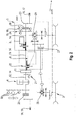
- Die Erfindung ist nachstehend anhand eines Ausführungsbeispiels, das in den Figuren dargestellt ist, näher erläutert. Es zeigt:
- Fig. 1:
- Eine Seitenansicht einer erfindungsgemäßen Arbeitsmaschine und
- Fig. 2:
- Eine schematische Darstellung eines Antriebsstrangs der erfindungsgemäßen Arbeitsmaschine gemäß
Figur 1 . - Ein Ausführungsbeispiel, das in den
Figuren 1 und2 gezeigt ist, umfasst eine erfindungsgemäße Arbeitsmaschine 1, die hier von einem Traktor gebildet ist. Die Arbeitsmaschine 1 umfasst eine Vorderachse 2 sowie eine Hinterachse 3, wobei an der Vorderachse 2 zwei als Rundräder ausgebildete Vorderräder 7 sowie an einer Hinterachse 3 zwei als Rundräder ausgebildete Hinterräder 8 angeordnet sind. In einem vorderen Bereich 9 der Arbeitsmaschine 1 weist die Arbeitsmaschine 1 eine Motorhaube 20 auf, unterhalb der sich eine Verbrennungskraftmaschine 4 befindet, die inFigur 1 mittels einer gestrichelten Linie veranschaulicht ist. Die Verbrennungskraftmaschine 4 ist hier von einem Dieselmotor gebildet. Die Verbrennungskraftmaschine 4 ist derart der Vorderachse 2 zugeordnet, dass das Eigengewicht der Verbrennungskraftmaschine 4 vollständig über die Vorderachse 2 sowie die Vorderräder 7 in einen Untergrund 30 abgeleitet wird. - Die Arbeitsmaschine 2 umfasst neben der Verbrennungskraftmaschine 4 ferner ein Hybridmodul 5, das hier von einem Elektromotor gebildet ist. Das Hybridmodul 5 ist erfindungsgemäß der Hinterachse 3 zugeordnet, wobei sich der Schwerpunkt des Hybridmoduls 5 in einem gedachten, von den Hinterrädern 8 aufgespannten Zylinderraum befindet. In dem gezeigten Beispiel ist das Hybridmodul 5 in die Hinterachse 3 integriert, sodass hier 100 % des Eigengewichts des Hybridmoduls 5 über die Hinterräder 8 in den Untergrund 30 abgeleitet werden. Das Hybridmodul 5 ist mithin einem Hinterbereich 10 der Arbeitsmaschine 2 zugeordnet.
- Die Verbrennungskraftmaschine 4 wirkt mit einer ihr zugeordneten Abtriebswelle 12 zusammen, mittels der eine Ausgangsleistung der Arbeitsmaschine 4 an nachgeschaltete Verbraucher leitbar ist. In dem gezeigten Beispiel erstreckt sich die Abtriebswelle 12 ausgehend von der Verbrennungskraftmaschine 4 sowohl in Richtung eines vorderen Endes der Arbeitsmaschine 2 als auch in Richtung eines hinteren Endes. Auf diese Weise können mittels der Verbrennungskraftmaschine 4 sowohl vorderseitige Verbraucher 18 als auch rückseitige Verbraucher 15 mit einer entsprechenden Leistung versorgt werden. An dem vorderen Ende weist die Arbeitsmaschine 1 beispielsweise eine Zapfwelle 19 auf, die mittels einer Kupplung 25 mit der Abtriebswelle 12 bedarfsweise koppelbar ist. Ferner befindet sich die Abtriebswelle 12 in Wirkverbindung mit weiteren Verbrauchern 18, die hier beispielsweise von einem Kompressor, einem Ventilator und einem Generator gebildet sind. An der Abtriebswelle 12 der Verbrennungskraftmaschine 4 ist ferner eine Bremse 21 angeordnet, mittels der ein Bremsmoment auf die Abtriebswelle 12 aufbringbar ist. Ferner wirkt die Antriebswelle 12 mit einem Schwungraddämpfer 11 zusammen. Dieser ist in Richtung des Kraftflusses betrachtet diesseits einer Getriebeeinrichtung 6 angeordnet, die mit der Abtriebswelle 12 zusammenwirkt. Die Abtriebswelle 12 ist der Getriebeeinrichtung 6 von dem vorderen Bereich 9 der Arbeitsmaschine 1 aus zugeführt, wobei die Getriebeeinrichtung 6 einen entsprechenden Eingang aufweist.
- Das Hybridmodul 5 wirkt seinerseits ebenfalls mit einer Abtriebswelle 13 zusammen, die sich sowohl in Richtung des Vorderbereichs 9 als auch eines hinteren Endes der Arbeitsmaschine 1 erstreckt. Die Getriebeeinrichtung 6 ist in dem gezeigten Beispiel unmittelbar an die Hinterachse 3 angeschlossen, wobei sich die Abtriebswelle 13 des Hybridmoduls 5 lediglich über eine kurze Strecke von dem Hybridmodul 5 zu der Getriebeeinrichtung 6 erstreckt. Die Abtriebswelle 12 der Verbrennungskraftmaschine 4 hingegen läuft von dem vorderen Bereich 9 aus bis zu der dem Hinterbereich 10 zugeordneten Getriebeeinrichtung 6 durch. Die Getriebeeinrichtung 6 ist dabei derart der Hinterachse 3 zugeordnet, dass ihr Eigengewicht zu mindestens 75 % über die Hinterachse 3 und mithin die Hinterräder 8 in den Untergrund 30 abgeleitet wird. Ausgehend von den Abtriebswellen 12, 13 werden Ausgangsleistungen der Verbrennungskraftmaschine 4 und des Hybridmoduls 5 mittels einer Abzweigung 22 abgezweigt und auf diese Weise der Getriebeeinrichtung 6 zugeführt. Diese wirkt im Bereich der Hinterachse 3 mit einem Differentialgetriebe 29 zusammen, mittels dessen die Ausgangsleistungen auf die beiden Hinterräder 8 aufgeteilt wird. Ferner ist der Getriebeeinrichtung 6 eine weitere Abzweigung 31 nachgeschaltet, mittels der ein Teil der Ausgangsleistung bedarfsweise über eine Kupplung 27 der Vorderachse 2 zuleitbar ist. Auch die Vorderachse 2 ist mit einem Differentialgetriebe 28 ausgestattet, sodass auch hier eine Kraftverteilung auf die beiden Vorderräder 7 vorgenommen werden kann.
- Da die Verbrennungskraftmaschine 4 und das Hybridmodul 5 separat voneinander mittels zugeordnete Abtriebswellen 12, 13 ihre jeweiligen Ausgangsleistungen der Getriebeeinrichtung 6 zuleiten, müssen die Abtriebswellen 12, 13 nicht für eine Summe der Ausgangsleistungen der Verbrennungskraftmaschine 4 und des Hybridmoduls 5 ausgelegt sein. Dies betrifft insbesondere den Schwungraddämpfer 11, der lediglich mit der Ausgangsleistung der Verbrennungskraftmaschine 4 beaufschlagt wird.
- In dem Hinterbereich 10 der Arbeitsmaschine 1 sind weitere Verbraucher 15 angeordnet, die mittels der Verbrennungskraftmaschine 4 und des Hybridmoduls 5 versorgbar sind. Die Verbraucher sind hier von zwei Hydraulikpumpen 16 sowie einer Zapfwelle 17 gebildet. Zum Anschluss dieser Verbraucher 15 an die Verbrennungskraftmaschine 4 und des Hybridmoduls 5 erstreckt sich die Abtriebswelle 13 des Hybridmoduls 12 ausgehend von dem Hybridmodul 5 bis zu einem hinteren Ende der Arbeitsmaschine 1. Dort wirkt die Abtriebswelle 13 mit einem Pumpenverteilergetriebe 24 zusammen, mittels dessen eine von der Abtriebswelle 13 abgenommenen Ausgangsleistung an die beiden Hydraulikpumpen 16 verteilt wird. Jenseits des Pumpenverteilergetriebes 24 ist ferner eine Kupplung 26 angeordnet, mittels der die Abtriebswelle 13 mittelbar mit der Zapfwelle 17 koppelbar ist. Hierbei ist in dem gezeigten Beispiel eine Untersetzung 23 zwischengeschaltet.
- In besonders vorteilhafter Weise sind die Abtriebswellen 12, 13 der Verbrennungskraftmaschine 4 und des Hybridmoduls 5 koaxial oder im rechten Winkel zueinander angeordnet und miteinander verbunden. Auf diese Weise bilden die Abtriebswellen 12, 13 Abtriebswellenabschnitte einer Hauptabtriebswelle 14, mittels der die Ausgangsleistungen der Arbeitsmaschine 4 und des Hybridmoduls 5 miteinander kombiniert werden können. Auf diese Weise ist die Möglichkeit gegeben, eine Ausgangsleistung der Verbrennungskraftmaschine 4 ausgehend von dem vorderen Bereich 9 der Arbeitsmaschine 1 bis in den hinteren Bereich 10 und den dortigen Verbrauchern 15 der Arbeitsmaschine 1 zu leiten, sodass die Verbraucher 15 zumindest zum Teil auch mittels der Ausgangsleistung der Verbrennungskraftmaschine 4 betreibbar sind. Hierbei ist es grundsätzlich vorstellbar, dass die von dem vorderen Bereich 9 bis in den hinteren Bereich 10 durchgeführte Hauptabtriebswelle 14 zumindest zeitweise ausschließlich die Ausgangsleistung der Verbrennungskraftmaschine 4 überträgt und die Verbraucher 15 entsprechend ausschließlich von der Verbrennungskraftmaschine 4 angetrieben werden. Gleichermaßen ist es denkbar, dass die Verbraucher 15 zumindest zeitweise ausschließlich mittels des Hybridmoduls das 5 angetrieben werden.
-
- 1
- Arbeitsmaschine
- 2
- Vorderachse
- 3
- Hinterachse
- 4
- Verbrennungskraftmaschine
- 5
- Hybridmodul
- 6
- Getriebeeinrichtung
- 7
- Vorderrad
- 8
- Hinterrad
- 9
- Vorderbereich
- 10
- Hinterbereich
- 11
- Schwungraddämpfer
- 12
- Abtriebswelle
- 13
- Abtriebswelle
- 14
- Hauptabtriebswelle
- 15
- Verbraucher
- 16
- Hydraulikpumpe
- 17
- Zapfwelle
- 18
- Verbraucher
- 19
- Zapfwelle
- 20
- Motorhaube
- 21
- Bremse
- 22
- Abzweigung
- 23
- Untersetzung
- 24
- Pumpenverteilergetriebe
- 25
- Kupplung
- 26
- Kupplung
- 27
- Kupplung
- 28
- Differentialgetriebe
- 29
- Differentialgetriebe
- 30
- Untergrund
- 31
- Abzweigung
Claims (14)
- Landwirtschaftliche Arbeitsmaschine (1), insbesondere in Form eines Traktors, umfassend- eine Vorderachse (2) und eine Hinterachse (3),- eine Verbrennungskraftmaschine (4),- mindestens ein Hybridmodul (5) sowie- eine Getriebeeinrichtung (6),wobei die Verbrennungskraftmaschine (4) und das Hybridmodul (5) jeweils mit der Getriebeeinrichtung (6) in Wirkverbindung stehen,
wobei mittels der Getriebeeinrichtung (6) sowohl eine Ausgangsleistung der Verbrennungskraftmaschine (4) als auch eine Ausgangsleistung des Hybridmoduls (5) aufnehmbar und die Ausgangsleistungen kombiniert an die Hinterachse (3) übertragbar ist, sodass an der Hinterachse (3) angeordnete Hinterräder (8) der Arbeitsmaschine (1) antreibbar sind,
wobei die Verbrennungskraftmaschine (4) in einem Vorderbereich (9) der Arbeitsmaschine (1) angeordnet ist,
dadurch gekennzeichnet, dass
das Hybridmodul (5) in einem Hinterbereich (10) der Arbeitsmaschine (1) angeordnet ist,
wobei die Ausgangsleistungen der Verbrennungskraftmaschine (4) und des Hybridmoduls (5) der Getriebeeinrichtung (6) separat zuführbar sind. - Arbeitsmaschine (1) nach Anspruch 1, dadurch gekennzeichnet, dass das Hybridmodul (5) nahe der Hinterachse (3) angeordnet ist.
- Arbeitsmaschine (1) nach Anspruch 1 oder 2, dadurch gekennzeichnet, dass das Hybridmodul (5) räumlich zwischen den Hinterrädern (8) angeordnet ist, wobei vorzugsweise sich ein Schwerpunkt des Hybridmoduls (5) in einem gedachten, durch als Rundräder ausgebildete Hinterräder (8) aufgespannten Zylinderraum befindet.
- Arbeitsmaschine (1) nach einem der vorhergehenden Ansprüche, dadurch gekennzeichnet, dass das Hybridmodul (5) in die Hinterachse (3) integriert ist.
- Arbeitsmaschine (1) nach einem der vorhergehenden Ansprüche, dadurch gekennzeichnet, dass die Getriebeeinrichtung (6) räumlich zwischen der Verbrennungskraftmaschine (4) und dem Hybridmodul (5) angeordnet ist.
- Arbeitsmaschine (1) nach einem der vorhergehenden Ansprüche, dadurch gekennzeichnet, dass das Hybridmodul (5) einen Elektromotor und/oder eine Hydromotor und/oder eine Elektromaschine und/oder eine Hydromaschine umfasst.
- Arbeitsmaschine (1) nach einem der vorhergehenden Ansprüche, dadurch gekennzeichnet, dass ein Schwungraddämpfer (11), der mit einer Abtriebswelle (12) der Verbrennungskraftmaschine (4) zusammenwirkt, - von der Verbrennungskraftmaschine (4) aus betrachtet - vor der Getriebeeinrichtung (6) angeordnet ist.
- Arbeitsmaschine (1) nach einem der vorhergehenden Ansprüche, dadurch gekennzeichnet, dass die Getriebeeinrichtung (6) räumlich der Hinterachse (3) zugeordnet ist, vorzugsweise räumlich zwischen den Hinterrädern (8) angeordnet ist.
- Arbeitsmaschine (1) nach einem der vorhergehenden Ansprüche, dadurch gekennzeichnet, dass Abtriebswellen (12, 13) der Verbrennungskraftmaschine (4) und des Hybridmoduls (5) koaxial oder im rechten Winkel zueinander angeordnet sind, wobei vorzugsweise die Abtriebswellen (12, 13) in Drehmoment übertragender Weise miteinander verbunden sind und gemeinsam eine Hauptabtriebswelle (14) bilden.
- Arbeitsmaschine nach Anspruch 9, dadurch gekennzeichnet, dass die Hauptabtriebswelle (14) von der Verbrennungskraftmaschine (4) bis in den Hinterbereich (10) der Arbeitsmaschine (1) durchläuft.
- Arbeitsmaschine nach Anspruch 10, dadurch gekennzeichnet, dass die Hauptabtriebswelle (14) im Hinterbereich (10) mit mindestens einem Verbraucher (15), vorzugsweise einer Mehrzahl von Verbrauchern (15), zusammenwirkt, insbesondere mindestens einer Hydraulikpumpe (16) und/oder mindestens einer Zapfwelle (17).
- Arbeitsmaschine nach Anspruch 11, dadurch gekennzeichnet, dass das Hybridmodul (5) - von der Verbrennungskraftmaschine (4) aus betrachtet - diesseits des mindestens einen Verbrauchers (15) an die Hauptabtriebswelle (14) angeschlossen ist, sodass der Verbraucher (15) im Bedarfsfall mit einer kombinierten Leistung der Verbrennungskraftmaschine (4) und des Hybridmoduls (5) versorgbar ist.
- Arbeitsmaschine (1) nach einem der vorhergehenden Ansprüche, dadurch gekennzeichnet, dass eine Abtriebswelle (12) der Verbrennungskraftmaschine (4) in dem Vorderbereich (9) der Arbeitsmaschine (1) mit mindestens einem Verbraucher (18), vorzugsweise einer Mehrzahl von Verbrauchern (18), zusammenwirkt, insbesondere mit mindestens einer Zapfwelle (19).
- Arbeitsmaschine (1) nach einem der vorhergehenden Ansprüche,
gekennzeichnet durch mindestens einen Stromgenerator, vorzugsweise einen Hochvoltgenerator, der im Hinterbereich (10) der Arbeitsmaschine (1) angeordnet ist, vorzugsweise nah der Hinterachse (3), weiter vorzugsweise räumlich zwischen den Hinterrädern (8).
Applications Claiming Priority (1)
| Application Number | Priority Date | Filing Date | Title |
|---|---|---|---|
| DE102020117283.4A DE102020117283A1 (de) | 2020-07-01 | 2020-07-01 | Landwirtschaftliche Arbeitsmaschine |
Publications (2)
| Publication Number | Publication Date |
|---|---|
| EP3932716A1 true EP3932716A1 (de) | 2022-01-05 |
| EP3932716B1 EP3932716B1 (de) | 2025-07-09 |
Family
ID=76197310
Family Applications (1)
| Application Number | Title | Priority Date | Filing Date |
|---|---|---|---|
| EP21176812.2A Active EP3932716B1 (de) | 2020-07-01 | 2021-05-31 | Landwirtschaftliche arbeitsmaschine |
Country Status (3)
| Country | Link |
|---|---|
| US (1) | US11618309B2 (de) |
| EP (1) | EP3932716B1 (de) |
| DE (1) | DE102020117283A1 (de) |
Families Citing this family (2)
| Publication number | Priority date | Publication date | Assignee | Title |
|---|---|---|---|---|
| GB202310333D0 (en) * | 2023-07-05 | 2023-08-16 | Agco Int Gmbh | Agricultural machine with improved mounting volume |
| DE102024116420A1 (de) * | 2024-06-12 | 2025-12-18 | Schaeffler Technologies AG & Co. KG | Antriebsstrang für ein Nutzfahrzeug |
Citations (5)
| Publication number | Priority date | Publication date | Assignee | Title |
|---|---|---|---|---|
| DE102011102265A1 (de) * | 2011-05-23 | 2012-04-12 | Daimler Ag | Anordnung eines Antriebsstrangs an einem Aufbau eines Kraftwagens |
| EP3098106A1 (de) * | 2015-05-26 | 2016-11-30 | IVECO S.p.A. | Multimodales hybrides antriebssystem für fahrzeuge mit zapfwelle und hybridfahrzeug mit zapfwelle mit diesem antriebssystem |
| DE102016005804A1 (de) * | 2016-05-11 | 2017-11-16 | Audi Ag | Antriebseinrichtung für ein Kraftfahrzeug sowie Verfahren zum Betreiben einer Antriebseinrichtung |
| WO2018227310A1 (en) * | 2017-06-16 | 2018-12-20 | Litens Automotive Partnership | Drive arrangement permitting driving of a vehicle by an electric motor |
| DE102018218078A1 (de) | 2017-11-29 | 2019-05-29 | Deere & Company | Integriertes hybridantriebssystem für ein arbeitsfahrzeug |
Family Cites Families (6)
| Publication number | Priority date | Publication date | Assignee | Title |
|---|---|---|---|---|
| US1613646A (en) * | 1925-06-24 | 1927-01-11 | Russell L Dailey | Selective power transmission |
| IT1396100B1 (it) * | 2009-10-06 | 2012-11-16 | Facma S R L | Trattrice agricola. |
| US10655710B2 (en) * | 2013-12-31 | 2020-05-19 | Deere & Company | Multi-mode infinitely variable transmission that provides seamless shifting |
| US11091018B2 (en) * | 2018-05-11 | 2021-08-17 | Deere & Company | Powertrain with variable vertical drop distance |
| JP6718935B2 (ja) * | 2018-09-12 | 2020-07-08 | 本田技研工業株式会社 | 車両 |
| US10807459B2 (en) * | 2018-10-15 | 2020-10-20 | Deere & Company | Engine power delivery system with transmission gearing bypass |
-
2020
- 2020-07-01 DE DE102020117283.4A patent/DE102020117283A1/de not_active Withdrawn
-
2021
- 2021-05-31 EP EP21176812.2A patent/EP3932716B1/de active Active
- 2021-07-01 US US17/364,960 patent/US11618309B2/en active Active
Patent Citations (5)
| Publication number | Priority date | Publication date | Assignee | Title |
|---|---|---|---|---|
| DE102011102265A1 (de) * | 2011-05-23 | 2012-04-12 | Daimler Ag | Anordnung eines Antriebsstrangs an einem Aufbau eines Kraftwagens |
| EP3098106A1 (de) * | 2015-05-26 | 2016-11-30 | IVECO S.p.A. | Multimodales hybrides antriebssystem für fahrzeuge mit zapfwelle und hybridfahrzeug mit zapfwelle mit diesem antriebssystem |
| DE102016005804A1 (de) * | 2016-05-11 | 2017-11-16 | Audi Ag | Antriebseinrichtung für ein Kraftfahrzeug sowie Verfahren zum Betreiben einer Antriebseinrichtung |
| WO2018227310A1 (en) * | 2017-06-16 | 2018-12-20 | Litens Automotive Partnership | Drive arrangement permitting driving of a vehicle by an electric motor |
| DE102018218078A1 (de) | 2017-11-29 | 2019-05-29 | Deere & Company | Integriertes hybridantriebssystem für ein arbeitsfahrzeug |
Also Published As
| Publication number | Publication date |
|---|---|
| EP3932716B1 (de) | 2025-07-09 |
| US20220001739A1 (en) | 2022-01-06 |
| US11618309B2 (en) | 2023-04-04 |
| DE102020117283A1 (de) | 2022-01-05 |
Similar Documents
| Publication | Publication Date | Title |
|---|---|---|
| DE202015102282U1 (de) | Hydrostatisch-mechanisches Leistungsverzweigungsgetriebe | |
| EP2215382B1 (de) | Leistungsverzweigungsgetriebe | |
| DE653589C (de) | Hydromechanische Kraftuebertragung fuer Landfahrzeuge, insbesondere Schienenfahrzeuge | |
| EP3647097B1 (de) | Motorfahrzeugantrieb | |
| DE102005019489A1 (de) | Allradangetriebenes Kraftfahrzeug | |
| EP3932716B1 (de) | Landwirtschaftliche arbeitsmaschine | |
| DE102019214636A1 (de) | Antriebssystem zum Antreiben eines Nebenaggregats eines Fahrzeugs mit elektrischem Antrieb | |
| DE102019209986A1 (de) | Antriebsstrang für eine Arbeitsmaschine und Arbeitsmaschine | |
| DE102008001614B4 (de) | Antriebsstrang eines Mähdreschers oder eines Feldhäckslers | |
| DE102022105401A1 (de) | Antriebsstrang, landwirtschaftliches Fahrzeug und Verfahren zum Betreiben eines Antriebstrangs | |
| DE102013111148B4 (de) | Antriebsstrang eines Hybrid-Kraftfahrzeuges | |
| DE102016214487B4 (de) | Schiffsantriebssystem | |
| EP2359676A1 (de) | Landwirtschaftliche Arbeitsmaschine | |
| EP2215381B1 (de) | Baukastensystem für ein hydrostatisch mechanisches lastschaltgetriebe | |
| DE102014208604A1 (de) | Antriebskonzept für einen Allradantrieb eines Fahrzeugs | |
| EP1600666B1 (de) | Antriebsanordnung für ein Fahrzeug | |
| DE202023100673U1 (de) | Antriebsvorrichtung für einen Kran und Kran | |
| DE2656474B2 (de) | Hydraulische Kriechgang-Antriebsanordnung für eine Nutzfahrzeug | |
| DE102021001651A1 (de) | Elektrifiziertes Radien-Überlagerungslenkgetriebe | |
| DE102005050640B4 (de) | Schiffsantrieb | |
| DE102014003374A1 (de) | Arbeitsmaschine, insbesondere Muldenkipper oder Truck | |
| DE102015222003A1 (de) | Antriebseinheit, Arbeitsmaschine und Anbaugerät | |
| DE102013019173A1 (de) | Antriebsstrang | |
| DE102019109001A1 (de) | Motorgetriebenes fahrzeug für die landwirtschaft | |
| DE102024207088A1 (de) | Antriebsanordnung für eine Arbeitsmaschine |
Legal Events
| Date | Code | Title | Description |
|---|---|---|---|
| PUAI | Public reference made under article 153(3) epc to a published international application that has entered the european phase |
Free format text: ORIGINAL CODE: 0009012 |
|
| STAA | Information on the status of an ep patent application or granted ep patent |
Free format text: STATUS: THE APPLICATION HAS BEEN PUBLISHED |
|
| AK | Designated contracting states |
Kind code of ref document: A1 Designated state(s): AL AT BE BG CH CY CZ DE DK EE ES FI FR GB GR HR HU IE IS IT LI LT LU LV MC MK MT NL NO PL PT RO RS SE SI SK SM TR |
|
| B565 | Issuance of search results under rule 164(2) epc |
Effective date: 20210929 |
|
| STAA | Information on the status of an ep patent application or granted ep patent |
Free format text: STATUS: REQUEST FOR EXAMINATION WAS MADE |
|
| 17P | Request for examination filed |
Effective date: 20220705 |
|
| RBV | Designated contracting states (corrected) |
Designated state(s): AL AT BE BG CH CY CZ DE DK EE ES FI FR GB GR HR HU IE IS IT LI LT LU LV MC MK MT NL NO PL PT RO RS SE SI SK SM TR |
|
| P01 | Opt-out of the competence of the unified patent court (upc) registered |
Effective date: 20230516 |
|
| STAA | Information on the status of an ep patent application or granted ep patent |
Free format text: STATUS: EXAMINATION IS IN PROGRESS |
|
| 17Q | First examination report despatched |
Effective date: 20241015 |
|
| GRAP | Despatch of communication of intention to grant a patent |
Free format text: ORIGINAL CODE: EPIDOSNIGR1 |
|
| STAA | Information on the status of an ep patent application or granted ep patent |
Free format text: STATUS: GRANT OF PATENT IS INTENDED |
|
| INTG | Intention to grant announced |
Effective date: 20250225 |
|
| GRAS | Grant fee paid |
Free format text: ORIGINAL CODE: EPIDOSNIGR3 |
|
| GRAA | (expected) grant |
Free format text: ORIGINAL CODE: 0009210 |
|
| STAA | Information on the status of an ep patent application or granted ep patent |
Free format text: STATUS: THE PATENT HAS BEEN GRANTED |
|
| AK | Designated contracting states |
Kind code of ref document: B1 Designated state(s): AL AT BE BG CH CY CZ DE DK EE ES FI FR GB GR HR HU IE IS IT LI LT LU LV MC MK MT NL NO PL PT RO RS SE SI SK SM TR |
|
| REG | Reference to a national code |
Ref country code: GB Ref legal event code: FG4D Free format text: NOT ENGLISH |
|
| REG | Reference to a national code |
Ref country code: CH Ref legal event code: EP |
|
| REG | Reference to a national code |
Ref country code: IE Ref legal event code: FG4D Free format text: LANGUAGE OF EP DOCUMENT: GERMAN |
|
| REG | Reference to a national code |
Ref country code: DE Ref legal event code: R096 Ref document number: 502021007943 Country of ref document: DE |
|
| REG | Reference to a national code |
Ref country code: NL Ref legal event code: MP Effective date: 20250709 |
|
| PG25 | Lapsed in a contracting state [announced via postgrant information from national office to epo] |
Ref country code: PT Free format text: LAPSE BECAUSE OF FAILURE TO SUBMIT A TRANSLATION OF THE DESCRIPTION OR TO PAY THE FEE WITHIN THE PRESCRIBED TIME-LIMIT Effective date: 20251110 |
|
| PG25 | Lapsed in a contracting state [announced via postgrant information from national office to epo] |
Ref country code: NL Free format text: LAPSE BECAUSE OF FAILURE TO SUBMIT A TRANSLATION OF THE DESCRIPTION OR TO PAY THE FEE WITHIN THE PRESCRIBED TIME-LIMIT Effective date: 20250709 |
|
| PG25 | Lapsed in a contracting state [announced via postgrant information from national office to epo] |
Ref country code: IS Free format text: LAPSE BECAUSE OF FAILURE TO SUBMIT A TRANSLATION OF THE DESCRIPTION OR TO PAY THE FEE WITHIN THE PRESCRIBED TIME-LIMIT Effective date: 20251109 |
|
| PG25 | Lapsed in a contracting state [announced via postgrant information from national office to epo] |
Ref country code: NO Free format text: LAPSE BECAUSE OF FAILURE TO SUBMIT A TRANSLATION OF THE DESCRIPTION OR TO PAY THE FEE WITHIN THE PRESCRIBED TIME-LIMIT Effective date: 20251009 |
|
| REG | Reference to a national code |
Ref country code: LT Ref legal event code: MG9D |
|
| PG25 | Lapsed in a contracting state [announced via postgrant information from national office to epo] |
Ref country code: FI Free format text: LAPSE BECAUSE OF FAILURE TO SUBMIT A TRANSLATION OF THE DESCRIPTION OR TO PAY THE FEE WITHIN THE PRESCRIBED TIME-LIMIT Effective date: 20250709 |
|
| PG25 | Lapsed in a contracting state [announced via postgrant information from national office to epo] |
Ref country code: HR Free format text: LAPSE BECAUSE OF FAILURE TO SUBMIT A TRANSLATION OF THE DESCRIPTION OR TO PAY THE FEE WITHIN THE PRESCRIBED TIME-LIMIT Effective date: 20250709 |
|
| PG25 | Lapsed in a contracting state [announced via postgrant information from national office to epo] |
Ref country code: GR Free format text: LAPSE BECAUSE OF FAILURE TO SUBMIT A TRANSLATION OF THE DESCRIPTION OR TO PAY THE FEE WITHIN THE PRESCRIBED TIME-LIMIT Effective date: 20251010 |
|
| PG25 | Lapsed in a contracting state [announced via postgrant information from national office to epo] |
Ref country code: SE Free format text: LAPSE BECAUSE OF FAILURE TO SUBMIT A TRANSLATION OF THE DESCRIPTION OR TO PAY THE FEE WITHIN THE PRESCRIBED TIME-LIMIT Effective date: 20250709 |
|
| PG25 | Lapsed in a contracting state [announced via postgrant information from national office to epo] |
Ref country code: LV Free format text: LAPSE BECAUSE OF FAILURE TO SUBMIT A TRANSLATION OF THE DESCRIPTION OR TO PAY THE FEE WITHIN THE PRESCRIBED TIME-LIMIT Effective date: 20250709 |
|
| PG25 | Lapsed in a contracting state [announced via postgrant information from national office to epo] |
Ref country code: BG Free format text: LAPSE BECAUSE OF FAILURE TO SUBMIT A TRANSLATION OF THE DESCRIPTION OR TO PAY THE FEE WITHIN THE PRESCRIBED TIME-LIMIT Effective date: 20250709 Ref country code: PL Free format text: LAPSE BECAUSE OF FAILURE TO SUBMIT A TRANSLATION OF THE DESCRIPTION OR TO PAY THE FEE WITHIN THE PRESCRIBED TIME-LIMIT Effective date: 20250709 |
|
| PG25 | Lapsed in a contracting state [announced via postgrant information from national office to epo] |
Ref country code: RS Free format text: LAPSE BECAUSE OF FAILURE TO SUBMIT A TRANSLATION OF THE DESCRIPTION OR TO PAY THE FEE WITHIN THE PRESCRIBED TIME-LIMIT Effective date: 20251009 |
|
| PG25 | Lapsed in a contracting state [announced via postgrant information from national office to epo] |
Ref country code: ES Free format text: LAPSE BECAUSE OF FAILURE TO SUBMIT A TRANSLATION OF THE DESCRIPTION OR TO PAY THE FEE WITHIN THE PRESCRIBED TIME-LIMIT Effective date: 20250709 |
|
| PG25 | Lapsed in a contracting state [announced via postgrant information from national office to epo] |
Ref country code: SM Free format text: LAPSE BECAUSE OF FAILURE TO SUBMIT A TRANSLATION OF THE DESCRIPTION OR TO PAY THE FEE WITHIN THE PRESCRIBED TIME-LIMIT Effective date: 20250709 |
|
| REG | Reference to a national code |
Ref country code: DE Ref legal event code: R026 Ref document number: 502021007943 Country of ref document: DE |
|
| PG25 | Lapsed in a contracting state [announced via postgrant information from national office to epo] |
Ref country code: DK Free format text: LAPSE BECAUSE OF FAILURE TO SUBMIT A TRANSLATION OF THE DESCRIPTION OR TO PAY THE FEE WITHIN THE PRESCRIBED TIME-LIMIT Effective date: 20250709 |
|
| PG25 | Lapsed in a contracting state [announced via postgrant information from national office to epo] |
Ref country code: IT Free format text: LAPSE BECAUSE OF FAILURE TO SUBMIT A TRANSLATION OF THE DESCRIPTION OR TO PAY THE FEE WITHIN THE PRESCRIBED TIME-LIMIT Effective date: 20250709 |
|
| PLBI | Opposition filed |
Free format text: ORIGINAL CODE: 0009260 |
|
| PLAX | Notice of opposition and request to file observation + time limit sent |
Free format text: ORIGINAL CODE: EPIDOSNOBS2 |
|
| PG25 | Lapsed in a contracting state [announced via postgrant information from national office to epo] |
Ref country code: CZ Free format text: LAPSE BECAUSE OF FAILURE TO SUBMIT A TRANSLATION OF THE DESCRIPTION OR TO PAY THE FEE WITHIN THE PRESCRIBED TIME-LIMIT Effective date: 20250709 |
|
| REG | Reference to a national code |
Ref country code: CH Ref legal event code: L10 Free format text: ST27 STATUS EVENT CODE: U-0-0-L10-L00 (AS PROVIDED BY THE NATIONAL OFFICE) Effective date: 20260423 |
|
| PG25 | Lapsed in a contracting state [announced via postgrant information from national office to epo] |
Ref country code: SK Free format text: LAPSE BECAUSE OF FAILURE TO SUBMIT A TRANSLATION OF THE DESCRIPTION OR TO PAY THE FEE WITHIN THE PRESCRIBED TIME-LIMIT Effective date: 20250709 Ref country code: EE Free format text: LAPSE BECAUSE OF FAILURE TO SUBMIT A TRANSLATION OF THE DESCRIPTION OR TO PAY THE FEE WITHIN THE PRESCRIBED TIME-LIMIT Effective date: 20250709 |
|
| 26 | Opposition filed |
Opponent name: AGCO LIMITED Effective date: 20260409 |
|
| PG25 | Lapsed in a contracting state [announced via postgrant information from national office to epo] |
Ref country code: LT Free format text: LAPSE BECAUSE OF FAILURE TO SUBMIT A TRANSLATION OF THE DESCRIPTION OR TO PAY THE FEE WITHIN THE PRESCRIBED TIME-LIMIT Effective date: 20250709 |
|
| PGFP | Annual fee paid to national office [announced via postgrant information from national office to epo] |
Ref country code: DE Payment date: 20260522 Year of fee payment: 6 |