EP3932703A1 - Independent linear suspension system - Google Patents
Independent linear suspension system Download PDFInfo
- Publication number
- EP3932703A1 EP3932703A1 EP21183345.4A EP21183345A EP3932703A1 EP 3932703 A1 EP3932703 A1 EP 3932703A1 EP 21183345 A EP21183345 A EP 21183345A EP 3932703 A1 EP3932703 A1 EP 3932703A1
- Authority
- EP
- European Patent Office
- Prior art keywords
- spindle
- spindle carrier
- pin
- aperture
- couple
- Prior art date
- Legal status (The legal status is an assumption and is not a legal conclusion. Google has not performed a legal analysis and makes no representation as to the accuracy of the status listed.)
- Withdrawn
Links
- 239000000725 suspension Substances 0.000 title claims abstract description 52
- 230000005540 biological transmission Effects 0.000 claims abstract description 4
- 230000004044 response Effects 0.000 claims abstract description 4
- 230000033001 locomotion Effects 0.000 claims description 21
- 238000000926 separation method Methods 0.000 claims 1
- 238000013016 damping Methods 0.000 description 5
- 239000000969 carrier Substances 0.000 description 3
- 230000014759 maintenance of location Effects 0.000 description 3
- 230000008878 coupling Effects 0.000 description 2
- 238000010168 coupling process Methods 0.000 description 2
- 238000005859 coupling reaction Methods 0.000 description 2
- 230000007246 mechanism Effects 0.000 description 2
- 230000000903 blocking effect Effects 0.000 description 1
- 230000008859 change Effects 0.000 description 1
- 238000005352 clarification Methods 0.000 description 1
- 230000002708 enhancing effect Effects 0.000 description 1
- 239000012530 fluid Substances 0.000 description 1
- 230000003534 oscillatory effect Effects 0.000 description 1
- 238000003971 tillage Methods 0.000 description 1
- 230000007704 transition Effects 0.000 description 1
Images




Classifications
-
- B—PERFORMING OPERATIONS; TRANSPORTING
- B60—VEHICLES IN GENERAL
- B60G—VEHICLE SUSPENSION ARRANGEMENTS
- B60G3/00—Resilient suspensions for a single wheel
- B60G3/01—Resilient suspensions for a single wheel the wheel being mounted for sliding movement, e.g. in or on a vertical guide
-
- B—PERFORMING OPERATIONS; TRANSPORTING
- B60—VEHICLES IN GENERAL
- B60G—VEHICLE SUSPENSION ARRANGEMENTS
- B60G3/00—Resilient suspensions for a single wheel
- B60G3/18—Resilient suspensions for a single wheel with two or more pivoted arms, e.g. parallelogram
- B60G3/20—Resilient suspensions for a single wheel with two or more pivoted arms, e.g. parallelogram all arms being rigid
- B60G3/26—Means for maintaining substantially-constant wheel camber during suspension movement ; Means for controlling the variation of the wheel position during suspension movement
-
- B—PERFORMING OPERATIONS; TRANSPORTING
- B60—VEHICLES IN GENERAL
- B60G—VEHICLE SUSPENSION ARRANGEMENTS
- B60G2200/00—Indexing codes relating to suspension types
- B60G2200/40—Indexing codes relating to the wheels in the suspensions
- B60G2200/44—Indexing codes relating to the wheels in the suspensions steerable
-
- B—PERFORMING OPERATIONS; TRANSPORTING
- B60—VEHICLES IN GENERAL
- B60G—VEHICLE SUSPENSION ARRANGEMENTS
- B60G2204/00—Indexing codes related to suspensions per se or to auxiliary parts
- B60G2204/10—Mounting of suspension elements
- B60G2204/12—Mounting of springs or dampers
- B60G2204/129—Damper mount on wheel suspension or knuckle
-
- B—PERFORMING OPERATIONS; TRANSPORTING
- B60—VEHICLES IN GENERAL
- B60G—VEHICLE SUSPENSION ARRANGEMENTS
- B60G2204/00—Indexing codes related to suspensions per se or to auxiliary parts
- B60G2204/10—Mounting of suspension elements
- B60G2204/14—Mounting of suspension arms
- B60G2204/148—Mounting of suspension arms on the unsprung part of the vehicle, e.g. wheel knuckle or rigid axle
-
- B—PERFORMING OPERATIONS; TRANSPORTING
- B60—VEHICLES IN GENERAL
- B60G—VEHICLE SUSPENSION ARRANGEMENTS
- B60G2204/00—Indexing codes related to suspensions per se or to auxiliary parts
- B60G2204/40—Auxiliary suspension parts; Adjustment of suspensions
- B60G2204/423—Rails, tubes, or the like, for guiding the movement of suspension elements
-
- B—PERFORMING OPERATIONS; TRANSPORTING
- B60—VEHICLES IN GENERAL
- B60G—VEHICLE SUSPENSION ARRANGEMENTS
- B60G2206/00—Indexing codes related to the manufacturing of suspensions: constructional features, the materials used, procedures or tools
- B60G2206/01—Constructional features of suspension elements, e.g. arms, dampers, springs
- B60G2206/50—Constructional features of wheel supports or knuckles, e.g. steering knuckles, spindle attachments
-
- B—PERFORMING OPERATIONS; TRANSPORTING
- B60—VEHICLES IN GENERAL
- B60G—VEHICLE SUSPENSION ARRANGEMENTS
- B60G2300/00—Indexing codes relating to the type of vehicle
- B60G2300/08—Agricultural vehicles
-
- B—PERFORMING OPERATIONS; TRANSPORTING
- B60—VEHICLES IN GENERAL
- B60G—VEHICLE SUSPENSION ARRANGEMENTS
- B60G2300/00—Indexing codes relating to the type of vehicle
- B60G2300/08—Agricultural vehicles
- B60G2300/082—Tractors
Definitions
- Work vehicles such as agricultural tractors, are used to tow a variety of equipment (e.g., planters, seeders, tillage implements) through a field.
- These work vehicles include suspension systems that dampen vibrations caused by uneven surfaces over which the work vehicle travels. By damping the vibrations, the suspension system may enhance the ride quality and reduce wear on work vehicle components.
- suspension systems may change the position of the wheel relative to the ground as the work vehicle travels over uneven surfaces. This may reduce uniform contact between the tires and the ground as well as affect handling and steering of the work vehicle.
- a work vehicle that includes a chassis.
- An independent linear suspension system couples to the chassis.
- the independent linear suspension system includes a driveshaft that couples to the chassis and to a transmission.
- a wheel hub couples to the driveshaft and rotates a wheel in response to rotation of the driveshaft.
- a spindle couples to the wheel hub.
- a spindle carrier couples to the spindle.
- the spindle carrier defines a first aperture and a second aperture.
- a first pin extends through the first aperture.
- a second pin extends through the second aperture.
- the first pin and the second pin block rotation of the spindle carrier.
- the spindle carrier moves linearly along the first pin and the second pin.
- an independent linear suspension system that includes a spindle that couples to a wheel hub.
- a spindle carrier that couples to the spindle.
- the spindle carrier defines a first aperture and a second aperture.
- a first pin extends through the first aperture.
- a second pin extends through the second aperture.
- the first pin and the second pin block rotation of the spindle carrier.
- the spindle carrier moves linearly along the first pin and the second pin.
- an independent linear suspension system that includes a spindle carrier.
- the spindle carrier includes a first spindle carrier arm defining a first aperture that receives a first pin.
- the spindle carrier includes a second spindle carrier arm that defines a second aperture that receives a second pin.
- the first spindle carrier arm and the second spindle carrier arm block rotation of the spindle carrier.
- the spindle carrier moves linearly over the first pin and the second pin.
- Coupled may indicate establishing either a direct or indirect connection, and is not limited to either unless expressly referenced as such.
- the term “set” may refer to one or more items.
- like or identical reference numerals are used in the figures to identify common or the same elements. The figures are not necessarily to scale and certain features and certain views of the figures may be shown exaggerated in scale for purposes of clarification.
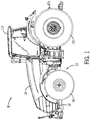
- FIG. 1 is a side view of an exemplary work vehicle 8 that may include an independent linear suspension system 10.
- the work vehicle 8 includes a chassis 12 (e.g., frame) configured to support a cab 14, a hood 16, front wheels 18, rear wheels 20, and various other components of the work vehicle 8.
- the cab 14 provides an enclosed space for an operator, and the hood 16 houses the engine and/or other systems configured to facilitate operation of the work vehicle 8 (e.g., hydraulic systems, pneumatic systems, electrical systems, mechanical systems, etc.).
- the wheels 18 and 20 are driven by the engine, thereby facilitating movement of the work vehicle 8 across a field, along a road, etc.
- the front wheels 18 and/or the rear wheels 20 are coupled to the independent linear suspension system 10 which enables relative motion between the wheels 18, 20 and the chassis 12.
- the independent linear suspension system 10 may include a respective axle or driveshaft that couples to a first wheel 18 on a first side of the work vehicle 8 and a second wheel 18 on a second side of the work vehicle 8.
- the independent linear suspension system 10 also includes a steering assembly configured to rotate each wheel 18 relative to the axle about a substantially vertical axis.
- the independent linear suspension system 10 includes damping cylinders that dampen movement of the wheels 18 and/or 20 as they transition between lowered and raised positions. More specifically, the damping cylinders are configured to enable movement of the axle or driveshaft with respect to the chassis 12 over a range of suspension travel. The damping cylinders thereby improve ride quality, and reduce wear on work vehicle components as the work vehicle 8 traverses an uneven surface (e.g., field).
- FIG. 2 is a perspective view of an embodiment of the independent linear suspension system 10 used by the work vehicle 8 of FIG. 1 .
- the independent linear suspension system 10 enables the wheel hub 40 to move vertically in directions 42 and 44 relative to the chassis 12 (axis 45 is perpendicular to directions 42 and 44). More specifically, the independent linear suspension system 10 enables wheels (e.g., wheels 18, 20) to move vertically without rotating (e.g., yaw rotation) through an arc in directions 46 and 48.
- wheels e.g., wheels 18, 20
- the independent linear suspension system 10 enables independent motion of the wheels 18 (seen in FIG. 1 ).
- the wheels 18 are configured to couple to the wheel hubs 40, which couple to respective driveshafts 50.
- the wheel hubs 40 secure the wheels 18 to the driveshafts 50 enabling the drive shafts 50 to rotate the wheels 18.
- the driveshafts 50 in turn couple to a transmission (not shown) with joints 52 (e.g., universal joints or u-joints).
- the wheel hubs 40 are supported by a spindle 54.
- the spindle 54 couples to a spindle carrier 56.
- the spindle 54 couples to the spindle carrier 56 with first pivot connector 58 and a second pivot connector 60.
- the first and second pivot connectors 58, 60 includes respective retention plates 62, 64 that couple (e.g., with bolts) to the spindle 54 to retain respective bearings (e.g., cylindrical bearing).
- the bearings in turn couple the spindle 54 to the spindle carrier 56 while also enabling the spindle 54 to rotate relative to the spindle carrier 56.
- the ability of the spindle 54 to rotate relative to the spindle carrier 56 enables a steering assembly 66 to rotate each wheel relative to the chassis 12.
- the steering assembly 66 is configured to rotate the wheels 18 through a range of motion that enables the work vehicle 8 to turn.
- the steering assembly 66 includes shafts or rods 68 (e.g., tie rods) that couple to the spindle 54 with a joint 70 (e.g., tie joint, knuckle).
- a steering mechanism e.g., steering wheel
- input from a steering mechanism is transferred through the rods 68 to the joint 70, which rotates the spindle 54 relative to the spindle carrier 56. Rotation of the spindle 54 then rotates the wheel hubs 40 and thus rotates the wheels 18.
- the spindle carrier 56 couples to the chassis 12 with pins 72.
- the pins 72 couple to and are supported by first and second chassis arms 74 and 76.
- the pins 72 may rest within apertures 77 defined by the first and second chassis arms 74 and 76.
- the first and second chassis arms 74 and 76 are separated from each other by a gap 78.
- the gap 78 accommodates the driveshaft 50, the spindle carrier 56, and may define the amount of vertical movement possible by the independent linear suspension system 10.
- the spindle carrier 56 moves within the gap 78 by sliding along the pins 72.
- the pins 72 couple to the spindle carrier 56 by extending through apertures 79 in the spindle carrier 56.
- the pins 72 and the spindle carrier 56 When coupled together the pins 72 and the spindle carrier 56 form a sliding joint 80 with the apertures 79 enabling the spindle carrier 56 to slide vertically up and down in directions 42 and 44.
- the apertures 79 may be located in arms 82 of the spindle carrier 56.
- the sliding joint 80 blocks rotational movement of the spindle carrier 56 in directions 46 and 48 so that the wheels 18 move vertically during operation of the independent linear suspension system 10.
- the independent linear suspension system 10 may enable uniform contact between the wheels 18 and the ground, use less complicated joints and bearings, enable better handling, and enable better steering.
- FIG. 3 is a front view of an embodiment of the independent linear suspension system 10 of FIG. 2 .
- the independent linear suspension system 10 enables the wheel hubs 40, and therefore wheels 18, to move independently of each other as well as vertically in directions 42 and 44 as the work vehicle 8 traverses uneven terrain.
- the independent linear suspension system 10 enables this vertical movement by forming the sliding joint 80 between the spindle carrier 56 and the pins 72. More specifically, the pins 72 control the direction of movement of the spindle carriers 56 and therefore direct the motion of the spindle carriers 56 vertically in directions 42 and 44.
- the independent linear suspension system 10 also damps vertical and oscillatory movement of the spindle carrier 56, thereby enhancing ride quality and reducing wear on certain work vehicle components.
- the independent linear suspension system 10 includes dampers 100 (e.g., damping cylinders).
- the dampers 100 include a piston 102 and a cylinder 104.
- a fluid e.g., oil, air
- a fluid within the cylinders 104 slows or reduces rapid movement of the pistons 102 as they move in and out of the cylinders 104.
- the dampers 100 damp vertical movement of the spindle carrier 56 and therefore the chassis 12 of the work vehicle 8 as it traverses an uneven field, thereby improving ride quality, and reducing wear on certain work vehicle components.
- the dampers 100 couple to the spindle carriers 56 and the chassis 12 with a connecting portion 105.
- the spindle carrier 56 may include a plurality of flanges 106 that couple to the piston 102 with a pin 108.
- the cylinder 104 may similarly couple to the chassis 12.
- the chassis 12 may include a plurality of flanges 110 that enable the chassis 12 to couple to the cylinders 104 with pins 112. It should be understood that the orientation of the dampers 100 may be reversed with the cylinder 104 coupling to the spindle carrier 56 and the piston 102 coupling to the chassis 12.
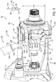
- FIG. 4 is a perspective rear view of an embodiment of the independent linear suspension system 10.
- the independent linear suspension system 10 enables the wheel hub 40 (seen in FIGS. 2 and 3 ) to move vertically in directions 42 and 44 relative to the chassis 12 (axis 45 is perpendicular to directions 42 and 44). More specifically, the independent linear suspension system 10 enables wheels (e.g., wheels 18, 20) to move vertically without rotating (e.g., yaw rotation) through an arc in directions 46 and 48.
- wheels e.g., wheels 18, 20
- the spindle carrier 56 couples to the chassis 12 with pins 72.
- the pins 72 couple to and are supported by the first and second chassis arms 74 and 76.
- the pins 72 may rest within the apertures 77 defined by the first and second chassis arms 74 and 76.
- the first and second chassis arms 74 and 76 are separated from each other by a gap 78.
- the gap 78 accommodates the driveshaft 50, the spindle carrier 56, and may define a distance 130 through which the spindle carrier 56 may travel. In other words, the distance 130 may be the distance that the independent linear suspension system 10 may travel.
- the spindle carrier 56 moves within the gap 78 by sliding along the pins 72.
- the pins 72 couple to the spindle carrier 56 forming the sliding joint 80.
- the sliding joint 80 blocks rotational movement of the spindle carrier 56 in directions 46 and 48 so that the wheels 18 move vertically during operation of the independent linear suspension system 10.
- the independent linear suspension system 10 may therefore enable uniform contact between the wheels 18 and the ground, use less complicated joints and bearings, enable better handling, and enable better steering.
- the spindle 54 couples to the spindle carrier 56 with the first pivot connector 58 and the second pivot connector 60.
- the first and second pivot connectors 58, 60 includes respective retention plates 62, 64 that couple (e.g., with bolts) to the spindle 54 to retain respective bearings (e.g., cylindrical bearing) between the spindle 54 and the spindle carrier 56. These bearings enable the spindle 54 to rotate relative to the spindle carrier 56.
- the ability of the spindle 54 to rotate relative to the spindle carrier 56 enables a steering assembly 66 to rotate the wheels 18 relative to the chassis 12.
- the steering assembly 66 is configured to rotate the wheels 18 through a range of motion that enables the work vehicle 8 to turn.
- the steering assembly 66 includes shafts or rods 68 (e.g., tie rods) that couple to the spindle 54 with a joint 70 (e.g., tie joint, knuckle).
- a joint 70 e.g., tie joint, knuckle
- input from a steering mechanism is transferred through the rods 68 to the joint 70, which rotates the spindle 54 relative to the spindle carrier 56.
- Rotation of the spindle 54 rotates the wheel hubs 40, which rotates the wheels 18.
- the spindle 54 may include a flange 132 that defines an aperture 134 that enables the joint 70 to couple to the spindle 54.
- the joint 70 may include a bolt 136 that extends through the aperture 134 and is secured to the flange 132 with a nut 138.
- FIG. 5 is a perspective rear view of an embodiment of the independent linear suspension system 10.
- the spindle carrier 56 couples to the chassis 12 with pins 72.
- the pins 72 couple to and are supported by the first and second chassis arms 74 and 76.
- the first and second chassis arms 74 and 76 are separated from each other by the gap 78.
- the gap 78 accommodates the driveshaft 50, the spindle carrier 56, and may define the distance 130 through which the spindle carrier 56 may travel.
- the spindle carrier 56 moves within the gap 78 by sliding along the pins 72.
- the pins 72 couple to the arms 82 of the spindle carrier 56 forming the sliding joint 80.
- the sliding joint 80 blocks rotational movement of the spindle carrier 56 in directions 46 and 48 enabling the wheels 18 to move vertically (e.g., only vertically, or along a single axis) during operation of the independent linear suspension system 10.
- the independent linear suspension system 10 may therefore enable uniform contact between the wheels 18 and the ground, use less complicated joints and bearings, enable better handling, and enable better steering.
- the spindle 54 couples to the spindle carrier 56 (seen in FIGS. 2-4 ) with the first pivot connector 58 and the second pivot connector 60.
- the first and second pivot connectors 58, 60 includes respective retention plates 62, 64 that couple with bolts 158 to the spindle 54 to retain respective bearings 160, 162 (e.g., cylindrical bearing) between the spindle 54 and the spindle carrier 56.
- bearings 160, 162 enable the spindle 54 to rotate relative to the spindle carrier 56.
- the ability of the spindle 54 to rotate relative to the spindle carrier 56 enables the steering assembly 66 to rotate the wheels 18 relative to the chassis 12.
- the steering assembly 66 is configured to rotate the wheels 18 through a range of motion that enables the work vehicle 8 to turn.
- the spindle carrier 56 defines an aperture 164.
- the driveshaft 50 extends through this aperture 164 and accommodates a joint 166 that enables the wheel hub 40 to couple to the driveshaft 50.
- the joint 166 enables the spindle 54 and the wheel hub 40 to rotate relative to the spindle carrier 56 in response to input from the steering assembly 66. Together, the spindle carrier 56 and spindle 54 form a housing that contains the joint 166.
- FIG. 6 is a perspective view of an embodiment of the spindle carrier 56.
- the spindle carrier 56 includes a body 190 that defines the cavity 168 and the aperture 164 in communication with the cavity 168.
- the spindle carrier 56 couples to the spindle 54 with the first pivot connector 58 and the second pivot connector 60. More specifically, the spindle carrier 56 and the spindle 54 couple together with bearings 160 and 162.
- the spindle carrier 56 receives these bearings 160, 162 in respective grooves or recesses 192, 194 formed in the body 190.
- the spindle carrier 56 may include the arms 82 that define the apertures 79.
- the flanges 106 may couple to and/or extend from the arms 82.
- the flanges 106 define respective apertures 196 that are aligned with and offset from each other by a distance 198.
- the distance 198 enables a portion of the piston 102 or cylinder 104 (e.g., connecting portion 105) to be placed between the flanges 106, which is then coupled to the flanges 106 with the pin 108.
- the terms “inner” and “outer”; “up” and “down”; “upper” and “lower”; “upward” and “downward”; “above” and “below”; “inward” and “outward”; and other like terms as used herein refer to relative positions to one another and are not intended to denote a particular direction or spatial orientation.
- the terms “couple,” “coupled,” “connect,” “connection,” “connected,” “in connection with,” and “connecting” refer to “in direct connection with” or “in connection with via one or more intermediate elements or members.”
Landscapes
- Engineering & Computer Science (AREA)
- Mechanical Engineering (AREA)
- Vehicle Body Suspensions (AREA)
Abstract
Description
- This section is intended to introduce the reader to various aspects of art that may be related to various aspects of the present disclosure, which are described below. This discussion is believed to be helpful in providing the reader with background information to facilitate a better understanding of the various aspects of the present disclosure. Accordingly, it should be understood that these statements are to be read in this light, and not as admissions of prior art.
- Work vehicles, such as agricultural tractors, are used to tow a variety of equipment (e.g., planters, seeders, tillage implements) through a field. These work vehicles include suspension systems that dampen vibrations caused by uneven surfaces over which the work vehicle travels. By damping the vibrations, the suspension system may enhance the ride quality and reduce wear on work vehicle components. Unfortunately, suspension systems may change the position of the wheel relative to the ground as the work vehicle travels over uneven surfaces. This may reduce uniform contact between the tires and the ground as well as affect handling and steering of the work vehicle.
- This summary is provided to introduce a selection of concepts that are further described below in the detailed description. This summary is not intended to identify key or essential features of the claimed subject matter, nor is it intended to be used as an aid in limiting the scope of the claimed subject matter.
- In one example, a work vehicle that includes a chassis. An independent linear suspension system couples to the chassis. The independent linear suspension system includes a driveshaft that couples to the chassis and to a transmission. A wheel hub couples to the driveshaft and rotates a wheel in response to rotation of the driveshaft. A spindle couples to the wheel hub. A spindle carrier couples to the spindle. The spindle carrier defines a first aperture and a second aperture. A first pin extends through the first aperture. A second pin extends through the second aperture. The first pin and the second pin block rotation of the spindle carrier. The spindle carrier moves linearly along the first pin and the second pin.
- In another example, an independent linear suspension system that includes a spindle that couples to a wheel hub. A spindle carrier that couples to the spindle. The spindle carrier defines a first aperture and a second aperture. A first pin extends through the first aperture. A second pin extends through the second aperture. The first pin and the second pin block rotation of the spindle carrier. The spindle carrier moves linearly along the first pin and the second pin.
- In another example, an independent linear suspension system that includes a spindle carrier. The spindle carrier includes a first spindle carrier arm defining a first aperture that receives a first pin. The spindle carrier includes a second spindle carrier arm that defines a second aperture that receives a second pin. The first spindle carrier arm and the second spindle carrier arm block rotation of the spindle carrier. The spindle carrier moves linearly over the first pin and the second pin.
- These and other features, aspects, and advantages of the present invention will become better understood when the following detailed description is read with reference to the accompanying drawings in which like characters represent like parts throughout the drawings, wherein:
-
FIG. 1 is a side view of an exemplary work vehicle that may include an independent linear suspension system, according to embodiments of the present disclosure. -
FIG. 2 is a perspective view of an embodiment of an independent linear suspension system that may be employed within the work vehicle ofFIG. 1 , according to embodiments of the present disclosure. -
FIG. 3 is a front view of an embodiment of an independent linear suspension system that may be employed within the work vehicle ofFIG. 1 , according to embodiments of the present disclosure. -
FIG. 4 is a partial perspective rear view of an embodiment of an independent linear suspension system that may be employed within the work vehicle ofFIG. 1 , according to embodiments of the present disclosure. -
FIG. 5 is a partial perspective rear view of an embodiment of an independent linear suspension system that may be employed within the work vehicle ofFIG. 1 , according to embodiments of the present disclosure. -
FIG. 6 is a perspective view of an embodiment of a spindle carrier of an independent linear suspension system that may be employed within the work vehicle ofFIG. 1 , according to embodiments of the present disclosure. - Certain embodiments commensurate in scope with the present disclosure are summarized below. These embodiments are not intended to limit the scope of the disclosure, but rather these embodiments are intended only to provide a brief summary of certain disclosed embodiments. Indeed, the present disclosure may encompass a variety of forms that may be similar to or different from the embodiments set forth below.
- As used herein, the term "coupled" or "coupled to" may indicate establishing either a direct or indirect connection, and is not limited to either unless expressly referenced as such. The term "set" may refer to one or more items. Wherever possible, like or identical reference numerals are used in the figures to identify common or the same elements. The figures are not necessarily to scale and certain features and certain views of the figures may be shown exaggerated in scale for purposes of clarification.
- Furthermore, when introducing elements of various embodiments of the present disclosure, the articles "a," "an," and "the" are intended to mean that there are one or more of the elements. The terms "comprising," "including," and "having" are intended to be inclusive and mean that there may be additional elements other than the listed elements. Additionally, it should be understood that references to "one embodiment" or "an embodiment" of the present disclosure are not intended to be interpreted as excluding the existence of additional embodiments that also incorporate the recited features. Furthermore, the phrase A "based on" B is intended to mean that A is at least partially based on B. Moreover, unless expressly stated otherwise, the term "or" is intended to be inclusive (e.g., logical OR) and not exclusive (e.g., logical XOR). In other words, the phrase A "or" B is intended to mean A, B, or both A and B.
-
FIG. 1 is a side view of an exemplary work vehicle 8 that may include an independentlinear suspension system 10. The work vehicle 8 includes a chassis 12 (e.g., frame) configured to support a cab 14, ahood 16,front wheels 18,rear wheels 20, and various other components of the work vehicle 8. The cab 14 provides an enclosed space for an operator, and thehood 16 houses the engine and/or other systems configured to facilitate operation of the work vehicle 8 (e.g., hydraulic systems, pneumatic systems, electrical systems, mechanical systems, etc.). Thewheels - The
front wheels 18 and/or therear wheels 20 are coupled to the independentlinear suspension system 10 which enables relative motion between thewheels chassis 12. For example, the independentlinear suspension system 10 may include a respective axle or driveshaft that couples to afirst wheel 18 on a first side of the work vehicle 8 and asecond wheel 18 on a second side of the work vehicle 8. The independentlinear suspension system 10 also includes a steering assembly configured to rotate eachwheel 18 relative to the axle about a substantially vertical axis. In addition, the independentlinear suspension system 10 includes damping cylinders that dampen movement of thewheels 18 and/or 20 as they transition between lowered and raised positions. More specifically, the damping cylinders are configured to enable movement of the axle or driveshaft with respect to thechassis 12 over a range of suspension travel. The damping cylinders thereby improve ride quality, and reduce wear on work vehicle components as the work vehicle 8 traverses an uneven surface (e.g., field). -
FIG. 2 is a perspective view of an embodiment of the independentlinear suspension system 10 used by the work vehicle 8 ofFIG. 1 . As will be explained below, the independentlinear suspension system 10 enables thewheel hub 40 to move vertically indirections axis 45 is perpendicular todirections 42 and 44). More specifically, the independentlinear suspension system 10 enables wheels (e.g.,wheels 18, 20) to move vertically without rotating (e.g., yaw rotation) through an arc indirections - In operation, the independent
linear suspension system 10 enables independent motion of the wheels 18 (seen inFIG. 1 ). Thewheels 18 are configured to couple to thewheel hubs 40, which couple torespective driveshafts 50. In operation, thewheel hubs 40 secure thewheels 18 to thedriveshafts 50 enabling thedrive shafts 50 to rotate thewheels 18. Thedriveshafts 50 in turn couple to a transmission (not shown) with joints 52 (e.g., universal joints or u-joints). - The
wheel hubs 40 are supported by aspindle 54. Thespindle 54 couples to aspindle carrier 56. Thespindle 54 couples to thespindle carrier 56 withfirst pivot connector 58 and asecond pivot connector 60. The first andsecond pivot connectors respective retention plates spindle 54 to retain respective bearings (e.g., cylindrical bearing). The bearings in turn couple thespindle 54 to thespindle carrier 56 while also enabling thespindle 54 to rotate relative to thespindle carrier 56. The ability of thespindle 54 to rotate relative to thespindle carrier 56 enables asteering assembly 66 to rotate each wheel relative to thechassis 12. The steeringassembly 66 is configured to rotate thewheels 18 through a range of motion that enables the work vehicle 8 to turn. The steeringassembly 66 includes shafts or rods 68 (e.g., tie rods) that couple to thespindle 54 with a joint 70 (e.g., tie joint, knuckle). In operation, input from a steering mechanism (e.g., steering wheel) is transferred through therods 68 to the joint 70, which rotates thespindle 54 relative to thespindle carrier 56. Rotation of thespindle 54 then rotates thewheel hubs 40 and thus rotates thewheels 18. - As illustrated, the
spindle carrier 56 couples to thechassis 12 withpins 72. Thepins 72 couple to and are supported by first andsecond chassis arms pins 72 may rest withinapertures 77 defined by the first andsecond chassis arms second chassis arms gap 78. Thegap 78 accommodates thedriveshaft 50, thespindle carrier 56, and may define the amount of vertical movement possible by the independentlinear suspension system 10. Thespindle carrier 56 moves within thegap 78 by sliding along thepins 72. Thepins 72 couple to thespindle carrier 56 by extending throughapertures 79 in thespindle carrier 56. When coupled together thepins 72 and thespindle carrier 56 form a sliding joint 80 with theapertures 79 enabling thespindle carrier 56 to slide vertically up and down indirections apertures 79 may be located inarms 82 of thespindle carrier 56. In this way, the sliding joint 80 blocks rotational movement of thespindle carrier 56 indirections wheels 18 move vertically during operation of the independentlinear suspension system 10. By directing thespindle carrier 56 vertically while simultaneously blocking rotation, the independentlinear suspension system 10 may enable uniform contact between thewheels 18 and the ground, use less complicated joints and bearings, enable better handling, and enable better steering. -
FIG. 3 is a front view of an embodiment of the independentlinear suspension system 10 ofFIG. 2 . As explained above, the independentlinear suspension system 10 enables thewheel hubs 40, and thereforewheels 18, to move independently of each other as well as vertically indirections linear suspension system 10 enables this vertical movement by forming the sliding joint 80 between thespindle carrier 56 and thepins 72. More specifically, thepins 72 control the direction of movement of thespindle carriers 56 and therefore direct the motion of thespindle carriers 56 vertically indirections - The independent
linear suspension system 10 also damps vertical and oscillatory movement of thespindle carrier 56, thereby enhancing ride quality and reducing wear on certain work vehicle components. In order to dampen the vertical motion of thespindle carrier 56, the independentlinear suspension system 10 includes dampers 100 (e.g., damping cylinders). Thedampers 100 include apiston 102 and acylinder 104. In operation, a fluid (e.g., oil, air) within thecylinders 104 slows or reduces rapid movement of thepistons 102 as they move in and out of thecylinders 104. In this way, thedampers 100 damp vertical movement of thespindle carrier 56 and therefore thechassis 12 of the work vehicle 8 as it traverses an uneven field, thereby improving ride quality, and reducing wear on certain work vehicle components. As illustrated, thedampers 100 couple to thespindle carriers 56 and thechassis 12 with a connectingportion 105. In some embodiments, thespindle carrier 56 may include a plurality offlanges 106 that couple to thepiston 102 with apin 108. Thecylinder 104 may similarly couple to thechassis 12. For example, thechassis 12 may include a plurality offlanges 110 that enable thechassis 12 to couple to thecylinders 104 withpins 112. It should be understood that the orientation of thedampers 100 may be reversed with thecylinder 104 coupling to thespindle carrier 56 and thepiston 102 coupling to thechassis 12. -
FIG. 4 is a perspective rear view of an embodiment of the independentlinear suspension system 10. As explained above, the independentlinear suspension system 10 enables the wheel hub 40 (seen inFIGS. 2 and3 ) to move vertically indirections axis 45 is perpendicular todirections 42 and 44). More specifically, the independentlinear suspension system 10 enables wheels (e.g.,wheels 18, 20) to move vertically without rotating (e.g., yaw rotation) through an arc indirections - As illustrated, the
spindle carrier 56 couples to thechassis 12 withpins 72. Thepins 72 couple to and are supported by the first andsecond chassis arms pins 72 may rest within theapertures 77 defined by the first andsecond chassis arms second chassis arms gap 78. Thegap 78 accommodates thedriveshaft 50, thespindle carrier 56, and may define adistance 130 through which thespindle carrier 56 may travel. In other words, thedistance 130 may be the distance that the independentlinear suspension system 10 may travel. Thespindle carrier 56 moves within thegap 78 by sliding along thepins 72. Thepins 72 couple to thespindle carrier 56 forming the sliding joint 80. The sliding joint 80 blocks rotational movement of thespindle carrier 56 indirections wheels 18 move vertically during operation of the independentlinear suspension system 10. The independentlinear suspension system 10 may therefore enable uniform contact between thewheels 18 and the ground, use less complicated joints and bearings, enable better handling, and enable better steering. - As explained above, the
spindle 54 couples to thespindle carrier 56 with thefirst pivot connector 58 and thesecond pivot connector 60. The first andsecond pivot connectors respective retention plates spindle 54 to retain respective bearings (e.g., cylindrical bearing) between thespindle 54 and thespindle carrier 56. These bearings enable thespindle 54 to rotate relative to thespindle carrier 56. The ability of thespindle 54 to rotate relative to thespindle carrier 56 enables asteering assembly 66 to rotate thewheels 18 relative to thechassis 12. The steeringassembly 66 is configured to rotate thewheels 18 through a range of motion that enables the work vehicle 8 to turn. The steeringassembly 66 includes shafts or rods 68 (e.g., tie rods) that couple to thespindle 54 with a joint 70 (e.g., tie joint, knuckle). In operation, input from a steering mechanism is transferred through therods 68 to the joint 70, which rotates thespindle 54 relative to thespindle carrier 56. Rotation of thespindle 54 rotates thewheel hubs 40, which rotates thewheels 18. In some embodiments, thespindle 54 may include aflange 132 that defines anaperture 134 that enables the joint 70 to couple to thespindle 54. For example, the joint 70 may include abolt 136 that extends through theaperture 134 and is secured to theflange 132 with anut 138. -
FIG. 5 is a perspective rear view of an embodiment of the independentlinear suspension system 10. As illustrated, thespindle carrier 56 couples to thechassis 12 withpins 72. Thepins 72 couple to and are supported by the first andsecond chassis arms second chassis arms gap 78. Thegap 78 accommodates thedriveshaft 50, thespindle carrier 56, and may define thedistance 130 through which thespindle carrier 56 may travel. Thespindle carrier 56 moves within thegap 78 by sliding along thepins 72. Thepins 72 couple to thearms 82 of thespindle carrier 56 forming the sliding joint 80. The sliding joint 80 blocks rotational movement of thespindle carrier 56 indirections wheels 18 to move vertically (e.g., only vertically, or along a single axis) during operation of the independentlinear suspension system 10. The independentlinear suspension system 10 may therefore enable uniform contact between thewheels 18 and the ground, use less complicated joints and bearings, enable better handling, and enable better steering. - As explained above, the
spindle 54 couples to the spindle carrier 56 (seen inFIGS. 2-4 ) with thefirst pivot connector 58 and thesecond pivot connector 60. The first andsecond pivot connectors respective retention plates bolts 158 to thespindle 54 to retainrespective bearings 160, 162 (e.g., cylindrical bearing) between thespindle 54 and thespindle carrier 56. Thesebearings spindle 54 to rotate relative to thespindle carrier 56. The ability of thespindle 54 to rotate relative to thespindle carrier 56 enables thesteering assembly 66 to rotate thewheels 18 relative to thechassis 12. The steeringassembly 66 is configured to rotate thewheels 18 through a range of motion that enables the work vehicle 8 to turn. - In order to transfer power from the
driveshaft 50 to the wheel hub 40 (seen inFIGS. 2 and3 ), thespindle carrier 56 defines anaperture 164. Thedriveshaft 50 extends through thisaperture 164 and accommodates a joint 166 that enables thewheel hub 40 to couple to thedriveshaft 50. In addition to transferring power, the joint 166 enables thespindle 54 and thewheel hub 40 to rotate relative to thespindle carrier 56 in response to input from the steeringassembly 66. Together, thespindle carrier 56 andspindle 54 form a housing that contains the joint 166. -
FIG. 6 is a perspective view of an embodiment of thespindle carrier 56. Thespindle carrier 56 includes abody 190 that defines thecavity 168 and theaperture 164 in communication with thecavity 168. As explained above, thespindle carrier 56 couples to thespindle 54 with thefirst pivot connector 58 and thesecond pivot connector 60. More specifically, thespindle carrier 56 and thespindle 54 couple together withbearings spindle carrier 56 receives thesebearings body 190. To couple to thepins 72, thespindle carrier 56 may include thearms 82 that define theapertures 79. Together thepins 72 and thearms 82 form the sliding joint 80 that enables thespindle carrier 56 to move vertically. In some embodiments, theflanges 106 may couple to and/or extend from thearms 82. Theflanges 106 definerespective apertures 196 that are aligned with and offset from each other by adistance 198. Thedistance 198 enables a portion of thepiston 102 or cylinder 104 (e.g., connecting portion 105) to be placed between theflanges 106, which is then coupled to theflanges 106 with thepin 108. - As used herein, the terms "inner" and "outer"; "up" and "down"; "upper" and "lower"; "upward" and "downward"; "above" and "below"; "inward" and "outward"; and other like terms as used herein refer to relative positions to one another and are not intended to denote a particular direction or spatial orientation. The terms "couple," "coupled," "connect," "connection," "connected," "in connection with," and "connecting" refer to "in direct connection with" or "in connection with via one or more intermediate elements or members."
Claims (15)
- A work vehicle (8), characterized in that the work vehicle (8) comprises:a chassis (12); andan independent linear suspension system (10) configured to couple to the chassis (12), the independent linear suspension system (10) comprises:a driveshaft (50) configured to couple to the chassis (12) and to a transmission;a wheel hub (40) coupled to the driveshaft (50) and configured to rotate a wheel (18, 20) in response to rotation of the driveshaft (50);a spindle (54) configured to couple to the wheel hub (40);a spindle carrier (56) configured to couple to the spindle (54), the spindle carrier (56) defining a first aperture (79) and a second aperture (79);a first pin (72) configured to extend through the first aperture (79); anda second pin (72) configured to extend through the second aperture (79), wherein the first pin (72) and the second pin (72) block rotation of the spindle carrier (56), and the spindle carrier (56) is configured to move linearly along the first pin (72) and the second pin (72).
- The work vehicle (8) of claim 1, wherein the chassis (12) comprises a first arm (74) and a second arm (76) separated by a gap (78), and the first pin (72) and the second pin (72) extend between the first arm (74) and the second arm (76) through the gap (78).
- The work vehicle (8) of any of claims 1-2, wherein the spindle (54) couples to the spindle carrier (56) with a pivot connector (58, 60), and the spindle (54) is configured to rotate relative to the spindle carrier (56) via the pivot connector (58, 60).
- The work vehicle (8) of claim 3, wherein the pivot connector (58, 60) comprises a bearing (160, 162) and a plate (62, 64), and the bearing (160, 162) is configured to couple to the spindle (54) and the spindle carrier (56), and the plate (62, 64) is configured to couple to the spindle (54) to block separation of the bearing (160, 162) from the spindle (54) and the spindle carrier (56).
- The work vehicle (8) of any of claims 1-4, comprising a steering assembly (66), wherein the steering assembly (66) is configured to couple to the spindle (54) to rotate the spindle (54) relative to the spindle carrier (56).
- The work vehicle (8) of any of claims 1-5, wherein the spindle carrier (56) defines a third aperture (164) that receives the driveshaft (50).
- The work vehicle (8) of any of claims 1-6, wherein the spindle carrier (56) defines a cavity (168), and the cavity is configured to receive a joint (52) that couples to the driveshaft (50).
- The work vehicle (8) of any of claims 1-7, wherein the spindle carrier (56) comprises a first spindle carrier arm (82) and a second spindle carrier arm (82), the first spindle carrier arm (82) defines the first aperture (79), and the second spindle carrier arm (82) defines the second aperture (79).
- The work vehicle (8) of any of claims 1-8, wherein the spindle carrier (56) comprises a flange (106), and the flange (106) is configured to couple to a damper (100).
- The work vehicle (8) of any of claims 1-9, comprising a damper (100) configured to couple to the spindle carrier (56) and to damp movement of the spindle carrier (56).
- An independent linear suspension system (10), characterized in that the independent linear suspension (10) comprises:a spindle (54) configured to couple to a wheel hub (40);a spindle carrier (56) configured to couple to the spindle (54), the spindle carrier (56) defining a first aperture (79) and a second aperture (79);a first pin (72) configured to extend through the first aperture (79); anda second pin (72) configured to extend through the second aperture (79), wherein the first pin (72) and the second pin (72) block rotation of the spindle carrier (56), and the spindle carrier (56) is configured to move linearly along the first pin (72) and the second pin (72).
- The independent linear suspension system (10) of claim 11, wherein the first pin (72) and the second pin (72) are configured to couple to a chassis (12) of a work vehicle (8).
- The independent linear suspension system (10) of any of claims 11-12, wherein the spindle (54) couples to the spindle carrier (56) with a pivot connector (58, 60), and the spindle (54) is configured to rotate relative to the spindle carrier (56) via the pivot connector (58, 60).
- The independent linear suspension system (10) of any of claims 11-13, wherein the spindle carrier (56) comprises a first spindle carrier arm (82) and a second spindle carrier arm (82), the first spindle carrier arm (82) defines the first aperture (79), and the second spindle carrier arm (82) defines the second aperture (79).
- The independent linear suspension system (10) of any of claims 11-14, wherein the spindle carrier (56) comprises a flange (106), and the flange (106) is configured to couple to a damper (100) that dampens movement of the independent linear suspension system (10).
Applications Claiming Priority (1)
| Application Number | Priority Date | Filing Date | Title |
|---|---|---|---|
| US202063047343P | 2020-07-02 | 2020-07-02 |
Publications (1)
| Publication Number | Publication Date |
|---|---|
| EP3932703A1 true EP3932703A1 (en) | 2022-01-05 |
Family
ID=76764853
Family Applications (1)
| Application Number | Title | Priority Date | Filing Date |
|---|---|---|---|
| EP21183345.4A Withdrawn EP3932703A1 (en) | 2020-07-02 | 2021-07-02 | Independent linear suspension system |
Country Status (3)
| Country | Link |
|---|---|
| US (1) | US11602966B2 (en) |
| EP (1) | EP3932703A1 (en) |
| BR (1) | BR102021013068A2 (en) |
Families Citing this family (1)
| Publication number | Priority date | Publication date | Assignee | Title |
|---|---|---|---|---|
| US11897295B2 (en) * | 2020-10-09 | 2024-02-13 | Cnh Industrial America Llc | Axle assembly having a tire inflation system |
Citations (3)
| Publication number | Priority date | Publication date | Assignee | Title |
|---|---|---|---|---|
| BE384043A (en) * | ||||
| EP0245220A1 (en) * | 1986-04-29 | 1987-11-11 | Janus Bus S.P.A. | A suspension for motored and unmotored wheels of vehicles |
| US20110148066A1 (en) * | 2009-12-20 | 2011-06-23 | William James Beaujon | Vehicle suspension, steering, damping and anti-roll system with linear wheel travel |
Family Cites Families (13)
| Publication number | Priority date | Publication date | Assignee | Title |
|---|---|---|---|---|
| US910491A (en) * | 1908-01-18 | 1909-01-26 | Raymond Bonnevie | Compensating elastic suspension device for vehicles. |
| US1002470A (en) * | 1910-02-08 | 1911-09-05 | Charles Durm Sword | Shock-absorber. |
| US2114937A (en) * | 1937-01-14 | 1938-04-19 | Poirier Maurice | Motor vehicle wheel suspension |
| IT1287898B1 (en) | 1996-05-14 | 1998-08-26 | Carraro Spa | SPRING AND VARIABILITY SYSTEM OF A DIFFERENTIAL BRIDGE |
| DE10145304B4 (en) | 2001-09-14 | 2005-12-22 | Daimlerchrysler Ag | Wheel suspension with Radträgerschubgelenken |
| GB0510990D0 (en) | 2005-05-28 | 2005-07-06 | Agco Gmbh | Steering systems |
| US7644942B2 (en) | 2007-03-22 | 2010-01-12 | Cnh America Llc | Active axle suspension system |
| FR2926492A1 (en) * | 2008-01-22 | 2009-07-24 | Peugeot Citroen Automobiles Sa | Running gear e.g. front gear, sub assembly for motor vehicle, has device for adjusting height of steering stub axle with respect to suspension system for adjusting ground clearance of vehicle independently of displacement of system |
| DE102008040505B4 (en) * | 2008-07-17 | 2021-04-01 | Zf Friedrichshafen Ag | Self-steering wheel suspension with straight guidance |
| US7837207B2 (en) * | 2008-08-19 | 2010-11-23 | Agco Corporation | Chassis adjustment system |
| DE102010022313A1 (en) * | 2010-06-01 | 2011-12-01 | Horsch Maschinen Gmbh | Independent suspension for a sprung, steerable wheel |
| FR2972963B1 (en) * | 2011-03-23 | 2013-03-29 | Poclain Hydraulics Ind | SUSPENSION ELEMENT FOR AUTOMOTIVE MACHINE |
| US9079470B2 (en) * | 2013-10-14 | 2015-07-14 | Agco Corporation | Vehicle with chassis height adjustment |
-
2021
- 2021-06-25 US US17/358,802 patent/US11602966B2/en active Active
- 2021-07-01 BR BR102021013068-7A patent/BR102021013068A2/en not_active Application Discontinuation
- 2021-07-02 EP EP21183345.4A patent/EP3932703A1/en not_active Withdrawn
Patent Citations (3)
| Publication number | Priority date | Publication date | Assignee | Title |
|---|---|---|---|---|
| BE384043A (en) * | ||||
| EP0245220A1 (en) * | 1986-04-29 | 1987-11-11 | Janus Bus S.P.A. | A suspension for motored and unmotored wheels of vehicles |
| US20110148066A1 (en) * | 2009-12-20 | 2011-06-23 | William James Beaujon | Vehicle suspension, steering, damping and anti-roll system with linear wheel travel |
Also Published As
| Publication number | Publication date |
|---|---|
| US20220001710A1 (en) | 2022-01-06 |
| US11602966B2 (en) | 2023-03-14 |
| BR102021013068A2 (en) | 2022-01-11 |
Similar Documents
| Publication | Publication Date | Title |
|---|---|---|
| US6915873B2 (en) | Suspended drive axle and agricultural tractor with same | |
| US5879016A (en) | Pivoting spring-mounted axle suspension | |
| US5782484A (en) | Short long arm independent suspension | |
| US4848789A (en) | Vehicle chassis tranverse structural member | |
| AU2010200923B2 (en) | Windrower tractor with rear wheel suspension | |
| US3630303A (en) | Front suspension for a front drive vehicle | |
| KR102677268B1 (en) | A corner module for vehicle | |
| US11602966B2 (en) | Independent linear suspension system | |
| US6322090B1 (en) | Suspension system with an oscillating, rigid axle, particularly for tractors | |
| US7758058B2 (en) | Front Steerable device for a vehicle | |
| CA2506823A1 (en) | Axle system with steering capability | |
| CN118386748A (en) | Single-arm independent suspension, multi-axle steering vehicle chassis and vehicle | |
| EP0287094B1 (en) | Automobile rear suspension structure | |
| AU2018231941A1 (en) | Modification of a two-wheel drive vehicle for improved ground clearance and/or traction | |
| US2842377A (en) | Vehicle suspension having differentially connected wheels | |
| CA2852288C (en) | Rear suspension for swather tractor | |
| KR200171146Y1 (en) | Rolling device of power truck | |
| US20250268116A1 (en) | Tractor | |
| US20250187660A1 (en) | Steering knuckle for increasing ground clearance of a vehicle | |
| US9415651B2 (en) | Rear suspension for swather tractor | |
| EP1547906A1 (en) | Suspension arrangement | |
| GB702454A (en) | Improvements in or relating to independent spring suspension of wheels of motor vehicles | |
| JPH06278431A (en) | Suspension device for vehicle | |
| IE62484B1 (en) | A vehicle chassis transverse structural member |
Legal Events
| Date | Code | Title | Description |
|---|---|---|---|
| PUAI | Public reference made under article 153(3) epc to a published international application that has entered the european phase |
Free format text: ORIGINAL CODE: 0009012 |
|
| STAA | Information on the status of an ep patent application or granted ep patent |
Free format text: STATUS: THE APPLICATION HAS BEEN PUBLISHED |
|
| AK | Designated contracting states |
Kind code of ref document: A1 Designated state(s): AL AT BE BG CH CY CZ DE DK EE ES FI FR GB GR HR HU IE IS IT LI LT LU LV MC MK MT NL NO PL PT RO RS SE SI SK SM TR |
|
| B565 | Issuance of search results under rule 164(2) epc |
Effective date: 20211126 |
|
| STAA | Information on the status of an ep patent application or granted ep patent |
Free format text: STATUS: REQUEST FOR EXAMINATION WAS MADE |
|
| 17P | Request for examination filed |
Effective date: 20220705 |
|
| RBV | Designated contracting states (corrected) |
Designated state(s): AL AT BE BG CH CY CZ DE DK EE ES FI FR GB GR HR HU IE IS IT LI LT LU LV MC MK MT NL NO PL PT RO RS SE SI SK SM TR |
|
| STAA | Information on the status of an ep patent application or granted ep patent |
Free format text: STATUS: EXAMINATION IS IN PROGRESS |
|
| 17Q | First examination report despatched |
Effective date: 20221103 |
|
| RAP3 | Party data changed (applicant data changed or rights of an application transferred) |
Owner name: CNH INDUSTRIAL ITALIA S.P.A. |
|
| STAA | Information on the status of an ep patent application or granted ep patent |
Free format text: STATUS: THE APPLICATION IS DEEMED TO BE WITHDRAWN |
|
| 18D | Application deemed to be withdrawn |
Effective date: 20230314 |