EP3932623A1 - Power transmission system for driving robot joint - Google Patents
Power transmission system for driving robot joint Download PDFInfo
- Publication number
- EP3932623A1 EP3932623A1 EP20763220.9A EP20763220A EP3932623A1 EP 3932623 A1 EP3932623 A1 EP 3932623A1 EP 20763220 A EP20763220 A EP 20763220A EP 3932623 A1 EP3932623 A1 EP 3932623A1
- Authority
- EP
- European Patent Office
- Prior art keywords
- wire
- driving
- force
- driving unit
- power transmission
- Prior art date
- Legal status (The legal status is an assumption and is not a legal conclusion. Google has not performed a legal analysis and makes no representation as to the accuracy of the status listed.)
- Pending
Links
Images









Classifications
-
- B—PERFORMING OPERATIONS; TRANSPORTING
- B25—HAND TOOLS; PORTABLE POWER-DRIVEN TOOLS; MANIPULATORS
- B25J—MANIPULATORS; CHAMBERS PROVIDED WITH MANIPULATION DEVICES
- B25J9/00—Program-controlled manipulators
- B25J9/10—Program-controlled manipulators characterised by positioning means for manipulator elements
- B25J9/104—Program-controlled manipulators characterised by positioning means for manipulator elements with cables, chains or ribbons
- B25J9/1045—Program-controlled manipulators characterised by positioning means for manipulator elements with cables, chains or ribbons comprising tensioning means
-
- B—PERFORMING OPERATIONS; TRANSPORTING
- B25—HAND TOOLS; PORTABLE POWER-DRIVEN TOOLS; MANIPULATORS
- B25J—MANIPULATORS; CHAMBERS PROVIDED WITH MANIPULATION DEVICES
- B25J9/00—Program-controlled manipulators
- B25J9/10—Program-controlled manipulators characterised by positioning means for manipulator elements
- B25J9/104—Program-controlled manipulators characterised by positioning means for manipulator elements with cables, chains or ribbons
-
- A—HUMAN NECESSITIES
- A61—MEDICAL OR VETERINARY SCIENCE; HYGIENE
- A61B—DIAGNOSIS; SURGERY; IDENTIFICATION
- A61B34/00—Computer-aided surgery; Manipulators or robots specially adapted for use in surgery
- A61B34/30—Surgical robots
-
- A—HUMAN NECESSITIES
- A61—MEDICAL OR VETERINARY SCIENCE; HYGIENE
- A61B—DIAGNOSIS; SURGERY; IDENTIFICATION
- A61B34/00—Computer-aided surgery; Manipulators or robots specially adapted for use in surgery
- A61B34/70—Manipulators specially adapted for use in surgery
- A61B34/71—Manipulators operated by drive cable mechanisms
-
- B—PERFORMING OPERATIONS; TRANSPORTING
- B25—HAND TOOLS; PORTABLE POWER-DRIVEN TOOLS; MANIPULATORS
- B25J—MANIPULATORS; CHAMBERS PROVIDED WITH MANIPULATION DEVICES
- B25J9/00—Program-controlled manipulators
- B25J9/10—Program-controlled manipulators characterised by positioning means for manipulator elements
- B25J9/12—Program-controlled manipulators characterised by positioning means for manipulator elements electric
- B25J9/126—Rotary actuators
-
- A—HUMAN NECESSITIES
- A61—MEDICAL OR VETERINARY SCIENCE; HYGIENE
- A61B—DIAGNOSIS; SURGERY; IDENTIFICATION
- A61B17/00—Surgical instruments, devices or methods
- A61B2017/00477—Coupling
-
- A—HUMAN NECESSITIES
- A61—MEDICAL OR VETERINARY SCIENCE; HYGIENE
- A61B—DIAGNOSIS; SURGERY; IDENTIFICATION
- A61B34/00—Computer-aided surgery; Manipulators or robots specially adapted for use in surgery
- A61B34/30—Surgical robots
- A61B2034/301—Surgical robots for introducing or steering flexible instruments inserted into the body, e.g. catheters or endoscopes
-
- B—PERFORMING OPERATIONS; TRANSPORTING
- B25—HAND TOOLS; PORTABLE POWER-DRIVEN TOOLS; MANIPULATORS
- B25J—MANIPULATORS; CHAMBERS PROVIDED WITH MANIPULATION DEVICES
- B25J18/00—Arms
- B25J18/06—Arms flexible
Definitions
- the present invention relates to a surgical robot, and more specifically, to a power transmission system for driving a robot joint.
- the simplest method is to directly attach an actuator to a link structure, but there is a disadvantage in that the actuator is very heavy.
- one motor should provide a force capable of pulling both of the two cables, that is, a master cable and a slave cable, in order to transmit a driving force to a target object.
- the present invention is directed to providing a power transmission system for driving a robot joint capable of controlling movement of a slave cable to increase a power transmission amount and improve control precision.
- the present invention is directed to providing a cartridge type power transmission system for driving a robot joint which allows a disposable cable to be conveniently replaced.
- One aspect of the present invention provides a power transmission system for driving a robot joint, which is a system for driving a joint of a robot, the power transmission system including a driving part including a first driving unit and a second driving unit, a first force transmission part including a first sheath formed to have a predetermined length, flexibility, and a hollow shape and a first wire which is inserted into the first sheath and of which one end is fixed to a joint of a robot and the other end is connected to the first driving unit, and a second force transmission part including a second sheath formed to have a predetermined length, flexibility, and a hollow shape and a second wire which is inserted into the second sheath and of which one end is fixed to the joint of the robot and the other end is connected to the second driving unit, wherein, in a case in which the first driving unit provides a force to the first wire in a first direction, the second driving unit provides a force to the second wire in a second direction opposite to the first direction.
- the second driving unit may provide a force to the second wire in a direction in which the second wire is pushed, and in a case in which the second driving unit applies a force to the second wire in a direction in which the second wire is pulled, the first driving unit may provide a force to the first wire in a direction in which the first wire is pushed.
- a magnitude of the force provided to the second wire by the second driving unit may be adjusted according to a friction force generated between the second wire and the second sheath.
- a magnitude of a maximum force provided to the second wire by the second driving unit may be the same as a magnitude of the friction force generated between the second wire and the second sheath.
- a magnitude of the force provided to the first wire by the first driving unit may be the same as a sum of a magnitude of a friction force generated between the first wire and the first sheath and a magnitude of a force which moves the joint of the robot
- a withdrawal length of the first wire withdrawn from an outer side of an end portion of the first sheath may be relatively greater than an insertion length of the second wire inserted into the second sheath from an end portion of the second sheath.
- a partial length, which includes the end portion of the second sheath into which the second wire is inserted, of an entire length of the second sheath may be in a state in which movement of the partial length is prevented with the second wire.
- a power transmission method of driving a robot joint may be provided as a cable power transmission method of driving a joint of a robot, wherein the method may include providing a force to the second wire using the second driving unit in the second direction opposite to the first direction.
- the power transmission system for driving a robot joint may further include a body part, a first elastic part of which one end is fixed to the body part and the other end is fixed to the first driving unit and which wraps the other end of the first wire, and a second elastic part of which one end is fixed to the body part and the other end is fixed to the second driving unit and which wraps the other end of the second wire, wherein the first driving unit and the second driving unit may move linearly.
- the power transmission system for driving a robot joint may further include a control part disposed in the body part, wherein the control part may control the first driving unit to provide the force to the first wire in the first direction and control the second driving unit to provide the force to the second wire in the second direction opposite to the first direction.
- a first wire hole through which the first wire passes and a second wire hole through which the second wire passes may be formed in one side of the body part.
- the first driving unit may include a first driving motor which generates a driving force and a first moving part which receives the driving force of the first driving motor to move linearly
- the second driving unit may include a second driving motor which generates a driving force and a second moving part which receives the driving force of the second driving motor to move linearly.
- the body part may include a first guide hole which guides the first moving part, and a second guide hole which guides the second moving part.
- Each of the first elastic part and the second elastic part receives a force in the first direction to contract and receives a force in the second direction to extend.
- a cartridge type power transmission system for driving a robot joint which is a power transmission system for driving a joint of a robot
- the cartridge type power transmission system including a housing, a first driving part disposed in the housing and moved linearly, and a cartridge inserted into the housing
- the cartridge includes a case, a moving part accommodated in the case, connected to the first driving part, and moved linearly, a force transmission part including a sheath formed to have a predetermined length, flexibility, and a hollow shape and a wire which is inserted into the sheath, of which one end is fixed to a joint of a robot and the other end is fixed to the moving part, and which passes through the case, and an elastic part of which one end is fixed to the case and the other end is fixed to the moving part and which wraps the wire, and the cartridge is detachably coupled to the housing.
- the cartridge type power transmission system may further include a second driving part which moves the first driving part so that the first driving part is connected to or separated from the moving part.
- the first driving part may include a driving body part which is movable in the housing, a first motor disposed in the driving body part, and a detachable part connected to the first motor, moved linearly by a driving force of the first motor, and detachably coupled to the moving part.
- the second driving part may include a second motor disposed in the housing, and a connection part connected to the second motor and moved linearly by a driving force of the second motor.
- the detachable part may include a protrusion protruding from an outer surface of the detachable part, and the moving part may include a detachable groove into which the protrusion of the detachable part is inserted.
- the cartridge may include a hole through which the force transmission part passes.
- the case may include a guide hole which guides movement of the moving part.
- the elastic part may extend in a first direction and contract in a second direction opposite to the first direction.
- a driving unit since a driving unit provides a driving force to a slave cable to cancel a friction force generated by the slave cable, even when a driving force having a small magnitude is provided to a master cable, a power transmission amount at a level which is greater than or equal to that in a conventional case can be obtained.
- a cartridge including the cable is detachably coupled to a housing, the cable used in surgery can be easily replaced.
- a "module” or “part” among components used in the embodiment performs at least one function or operation.
- the "module” or “part” may perform the function or operation using hardware, software, or combination thereof.
- a plurality of “modules” or “parts” excluding a “module” or “part” which should be performed by specific hardware or at least one processor may also be integrated as at least one module.
- a power transmission system 100 for driving a robot joint realizes a double input sheath-tendon power transmission mechanism and includes a driving part, a first force transmission part 120, and a second force transmission part 130 as illustrated in FIGS. 1 and 2 .
- the driving part may include a first driving unit 110a and a second driving unit 110b
- the first driving unit 110a may be directly connected to the first force transmission part 120 and may provide a driving force to the first force transmission part 120
- the second driving unit 110b may be directly connected to the second force transmission part 130 and may provide a driving force to the second force transmission part 130.
- a sheath-tendon mechanism in which a tendon is inserted into a sheath to be moved in a longitudinal direction therein may be employed.
- the first force transmission part 120 may include a first sheath 121 having a predetermined length, flexibility, and a hollow shape and a first wire 122 inserted into the first sheath 121.
- the first wire 122 may be inserted into the first sheath 121 so that both end portions of the first wire 122 are exposed to the outside of the first sheath 121, one end portion of both of the end portions, which are exposed to the outside, of the first wire 122 may be fixed to a control target object 10, and the other end portion thereof may be fixed to the first driving unit 110a.
- the second force transmission part 130 may include a second sheath 131 having a predetermined length, flexibility, and a hollow shape and a second wire 132 inserted into the second sheath 131.
- the second wire 132 may be inserted into the second sheath 131 so that both end portions of the second wire 132 are exposed to the outside of the second sheath 131, and one end portion of both of the end portions, which are exposed to the outside, of the second wire 132 may be fixed to the control target object 10, and the other end portion thereof may be fixed to the second driving unit 110b.
- the first driving unit 110a may include a first driving motor 112a and a first roller 114a rotatably coupled to the first driving motor 112a, and one end portion of the first wire 122 may be fixedly coupled to the first roller 114a.
- the second driving unit 110b may include a second driving motor 112b and a second roller 114b rotatably coupled to the second driving motor 112b, and one end portion of the second wire 132 may be fixedly coupled to the second roller 114b.
- the control target object 10 may be a driving joint of a robot, and the driving joint of the robot may be a driving joint for driving a finger or a wrist of the robot in a robot arm.
- each of the first sheath 121 and the second sheath 131 may be a coil shaped tube formed of a metal material to withstand tension applied to each of the first wire 122 and the second wire 132, to maintain an overall shape, and to have flexibility.
- the shape and the material of each of the first sheath 121 and the second sheath 131 are not limited thereto, and any shape and any material employed for a sheath in a known sheath-tendon mechanism may be applied thereto.
- the power transmission system 100 for driving a robot joint may further include a control part 140 for controlling overall operations of the first driving unit 110a and the second driving unit 110b, and the control part 140 may control driving of the first driving unit 110a and driving of the second driving unit 110b on the basis of an input signal of a user.
- the control part 140 may control a magnitude of a force provided to the first wire 122 from the first driving unit 110a and a magnitude of a force provided to the second wire 132 from the second driving unit 110b on the basis of the input signal of the user.
- the first force transmission part 120 in which the end portion of the first wire 122 is connected to the first driving unit 110a and the second force transmission part 130 in which the end portion of the second wire 132 is connected to the second driving unit 110b may be connected by the control target object 10, and in a case in which a driving force is transmitted to the first wire 122 from the first driving unit 110a, or a driving force is transmitted to the second wire 132 from the second driving unit 110b through control of the control part 140, the first wire 122 and the second wire 132 may move in the longitudinal directions in the first sheath 121 and the second sheath 131, respectively. Accordingly, the control target object 10 may be rotated or moved to a position desired by the user.
- the first driving unit 110a and the second driving unit 110b may provide a driving force to the first force transmission part 120 and a driving force to the second force transmission part 130 at the same time, and a magnitude of the driving force provided to the first force transmission part 120 and a magnitude of the driving force provided to the second force transmission part 130 from the first driving unit 110a and the second driving unit 110b, respectively, may be controlled by the control part 140.
- the second driving unit 110b may provide a force to the second wire 132 in a second direction opposite to the first direction.
- the first driving unit 110a may provide a force to the first wire 122 in the second direction opposite to the first direction.
- the first direction is defined as a direction of a force by which the first driving unit 110a pulls the first wire 122 or a direction of a force by which the second driving unit 110b pulls second wire 132
- the second direction is defined as a direction of a force by which the first driving unit 110a pushes the first wire 122, or a direction of a force by which the second driving unit 110b pushes the second wire 132.
- a role of a master cable and a role of a slave cable may be interchanged according to directions of forces provided from the first driving unit 110a and the second driving unit 110b.
- the first wire 122 may serve as the master cable, and the second wire 132 may serve as the slave cable.
- the second wire 132 may serve as the master cable, and the first wire 122 may serve as the slave cable.
- the second driving unit 110b may provide a force T2 to the second wire 132 in the second direction. Accordingly, the control target object 10 connected to the end portion of the first wire 122 and the end portion of the second wire 132 may be rotated in the first direction as illustrated in FIG. 2 .
- the first driving unit 110a may provide a force to the first wire 122 in the second direction. Accordingly, the control target object 10 connected to the end portion of the first wire 122 and the end portion of the second wire 132 may be rotated in the second direction.
- the force T1 in a case in which, among the first wire 122 and second wire 132, the force T1 is provided to any one wire serving as the master cable in the first direction in which the wire is pulled, the force T2 may be provided to the remaining wire serving as the slave cable in the second direction in which the wire is pushed.
- a friction force T3 generated due to contact between the wires and the sheaths in a process in which the wires moved in the sheaths may be compensated for.
- the control target object 10 may be moved to a desired position.
- the first wire 122 serves as the master cable which controls movement of the control target object 10 and the second wire 132 serves as the slave cable role
- the second wire 132 serves as the master cable which controls movement of the control target object 10 and the first wire 122 serves as the slave cable
- a magnitude and a direction of a force provided to the first wire 122 and a magnitude and a direction of a force provided to the second wire 132 are interchanged, the detailed description thereof will be omitted.
- the second driving unit 110b may provide the force T2 to the second wire 132 in the second direction.
- a magnitude of the force T2 provided to the second wire 132 in the second direction by the second driving unit 110b may be set on the basis of the friction force T3 generated between the second wire 132 and the second sheath 131 in a process in which the second wire 132 is moved toward the control target object 10 in the longitudinal direction of the second sheath 131.
- the magnitude of the force T2 provided to the second wire 132 in the second direction by the second driving unit 110b may be provided to be the same as a magnitude of the friction force T3 generated between the second wire 132 and the second sheath 131 in the process in which the second wire 132 is moved to the control target object 10 in the longitudinal direction of the second sheath 131.
- a magnitude of the force T1 provided to the first wire 122 in the first direction by the first driving unit 110a is the same as the sum of a magnitude of a friction force T11 generated between the first wire 122 and the first sheath 121 and a magnitude of a force T12 for moving the control target object 10 in a process in which the first wire 122 is moved toward the first driving unit 110a in the longitudinal direction of the first sheath 121, the control target object 10 may be moved to a position desired by a worker.
- a magnitude of the maximum force T2 provided to the second wire 132 in the second direction by the second driving unit 110b may be the same as the magnitude of the friction force T3 generated between the second wire 132 and the second sheath 131 in the process in which the second wire 132 is moved to the control target object 10 in the longitudinal direction of the second sheath 131.
- the magnitude of the maximum force T2 provided to the second wire 132 in the second direction by the second driving unit 110b may be smaller than the magnitude of the force T1 provided to the first wire 122 in the first direction by the first driving unit 110a.
- the end portion of the sheath may be fixed to the driving unit 110a or 110b.
- a partial length B which includes the end portion into which the second wire 132 is inserted, of an entire length of the second sheath 131 may be in a state in which movement of the partial length B is prevented with the second wire 132.
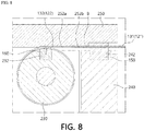
- the second sheath 131 may be fixed in a stated in which the partial length B, which includes the end portion into which the second wire 132 is inserted, of the entire length of the second sheath 131 is inserted into a guide groove 252 formed in a side of the second driving unit 110b in a direction parallel to the longitudinal direction, and the guide groove 252 may be formed so that a part, which is exposed to the outside, of the second wire 132 is seated on the guide groove 252 with the partial length B of the second sheath 131 (see FIG. 8 ).
- the second driving unit 110b provides a force to the second wire 132 in the second direction
- the partial length, which is exposed to the outside from the end portion of the second sheath 131, of the second wire 132 may be directly moved to the second sheath 131 along the guide groove 252
- the second wire 132 can be prevented from being loosened at a side of the end portion of the second sheath 131.
- the driving unit provides a driving force, which actively pushes the wire serving as the slave cable, to the wire to cancel a friction force generated between the wire serving as the slave cable and the sheath, even when a small magnitude of a driving force is provided to the wire serving as the master cable, a power transmission amount at a level which is greater than or equal to that in a conventional case can be obtained.
- each of the first driving unit 110a and the second driving unit 110b may be implemented as a cable driving apparatus 200 for driving a robot joint.
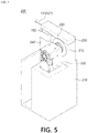
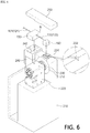
- each of the first driving unit 110a and the second driving unit 110b may be the cable driving apparatus 200 for driving a robot joint illustrated in FIGS. 5 to 7 , and in the cable driving apparatus 200 for driving a robot joint, a force that pulls a wire 122 or 132 to the outside of a sheath 121 or 131 or pushes the wire 122 or 132 into the sheath 121 or 131 may be provided by rotating a driving roller 230 using a driving motor 220 in a state in which a sheath holder 150, to which the sheath 121 or 131 is fixedly coupled, and a wire holder 160, to which an end portion of the wire 122 or 132 is fixed, are fixed.
- the sheath 121 or 131 may be the first sheath 121 or the second sheath 131 described above, and the wire 122 or 132 may be the first wire 122 or the second wire 132 described above.
- the first driving motor 112a and the first roller 114a constituting the first driving unit 110a may be the driving motor 220 and the driving roller 230, respectively, which will be described below.
- the second driving motor 112b and the second roller 114b constituting the second driving unit 110b may also be the driving motor 220 and the driving roller 230, respectively, which will be described below.
- the sheath 121 or 131 may be fixed to the sheath holder 150 so that both end portions of the sheath 121 or 131 protrude from the sheath holder 150 by a predetermined length, the wire 122 or 132 may pass through the sheath 121 or 131 fixed to the sheath holder 150 in a state in which one end portion of the wire 122 or 132 is fixed to a control target object 10, and the other end portion thereof may be fixed to the wire holder 160.
- the sheath holder 150 and the wire holder 160 may be installed in the cable driving apparatus 200 for driving a robot joint.
- the cable driving apparatus 200 for driving a robot joint may include a main body 210, the driving motor 220, the driving roller 230, and a weight measurement part 240.
- the main body 210 may serve as a fixture on which the driving motor 220, the driving roller 230, and the weight measurement part 240 are installed.
- the driving motor 220 may be disposed on one surface of the main body 210, and an arrangement hole 212 having a shape corresponding to the driving roller 230 may be formed in one surface of the main body 210 so that the driving roller 230 may be disposed in the arrangement hole 212.
- the driving roller 230 may be driven by a driving force provided from the driving motor 220 and rotatably disposed in the arrangement hole 212, and a first accommodation groove 232 for accommodating the wire holder 160 may be formed in one side of the driving roller 230.
- the driving motor 220 may include a speed reduction device, and the driving roller 230 may be rotatably coupled to the speed reduction device.
- the wire holder 160 to which the end portion of the wire 122 or 132 is fixed may also be rotated by the driving roller 230 to pull or push the wire 122 or 132.
- one side of the arrangement hole 212 may be formed to be open so that the first accommodation groove 232 is exposed to the outside. Accordingly, in a case in which the first accommodation groove 232 is disposed to be positioned in the arrangement hole 212 formed to be open, the wire holder 160 may be easily installed in the first accommodation groove 232.
- a seating groove 234 recessed inward in a circumferential direction may be formed in the driving roller 230 to accommodate a thickness of the wire 122 or 132. Accordingly, in a state in which a partial length of an entire length of the wire 122 or 132 passing through the sheath 121 or 131 is wound around the driving roller 230 at least one time along the seating groove 234, since the end portion of the wire 122 or 132 may be fixed to the wire holder 160, a force may be smoothly transmitted to the wire 122 or 132 by rotation.
- the driving motor 220 may be driven in a forward or reverse direction through control of a control part, and the control part may be the control part 140 described above.
- the weight measurement part 240 may be fixedly installed on one side of the main body 210, and a second accommodation groove 242 for accommodating the sheath holder 150 may be formed in one side. That is, the sheath holder 150, to which a partial length of the sheath 121 or 131 is fixedly coupled, may be detachably installed in the second accommodation groove 242.
- the weight measurement part 240 may be a load cell, and the second accommodation groove 242 may be directly formed in one side of the load cell or may also be formed as a separated member fixedly coupled to the load cell.
- the weight measurement part 240 may be disposed on one side of the driving roller 230 so that the wire 122 or 132 passing through the sheath 121 or 131 and exposed to the outside is linearly disposed toward the wire holder 160.
- the weight measurement part 240 may measure a force applied to the sheath holder 150 and may measure a force of the sheath 121 or 131 using the force applied to the sheath holder 150.
- the force applied to the wire 122 or 132 and the force applied to the sheath 121 or 131 are the same according to a relationship of action and reaction, the force applied to the wire 122 or 132 can be easily measured by measuring the force applied to the sheath holder 150.
- a force provided to the wire 122 or 132 through the driving motor 220 may be exactly controlled by control of the control part 140 on the basis of a magnitude of a load applied to the sheath holder 150.
- the cable driving apparatus 200 for driving a robot joint may include a cover 250 so that, in a case in which a force is applied to the wire 122 or 132 in a second direction, in which the wire 122 or 132 is pushed into the sheath 121 or 131, by driving of the driving motor 220, the wire 122 or 132 is not bent and is exactly moved into the sheath 121 or 131 by the applied force.
- the cable driving apparatus 200 for driving a robot joint may include the cover 250 having a cover surface 251 which covers an upper portion of the first accommodation groove 232 and an upper portion of the second accommodation groove 242 at the same time in an initial state in which the wire holder 160 and the sheath holder 150 are respectively installed in the first accommodation groove 232 and the second accommodation groove 242, and the first accommodation groove 232 is positioned at an open portion of the arrangement hole 212.
- the wire holder 160 and the sheath holder 150 respectively installed in the first accommodation groove 232 and the second accommodation groove 242 are pressed by the cover surface 251, the wire holder 160 and the sheath holder 150 may be prevented from being separated from the first accommodation groove 232 and the second accommodation groove 242, respectively.
- the cover 250 may also be detachably coupled to the main body 210, and alternatively, one side of the cover 250 may also be rotatably coupled to the main body 210.
- the cover surface 251 may include a guide groove 252 formed to be recessed so that a protruding portion B of the sheath 121 or 131 protruding toward the driving roller 230 from the sheath holder 150 and a part of the wire 122 or 132 exposed to the outside from an end portion of the protruding portion B of the sheath 121 or 131 are seated on the guide groove 252 at the same time in a state in which the sheath holder 150 is installed in the second accommodation groove 242.
- the guide groove 252 may include a first guide groove 252a for accommodating the protruding portion B of the sheath 121 or 131 and a second guide groove 252b for accommodating the wire 122 or 132 exposed to the outside from the end portion of the protruding portion B of the sheath 121 or 131, and the first guide groove 252a and the second guide groove 252b may be formed to be connected to each other.
- a bottom surface of the first guide groove 252a and a bottom surface of the second guide groove 252b may be formed as a stepped surface.
- the protruding portion B of the sheath 121 or 131 protruding from the sheath holder 150 toward the driving roller 230 may be connected to an end portion of the first accommodation groove 232.
- the cable driving apparatus 200 for driving a robot joint even when a force is applied to the wire 122 or 132 in the second direction which is a direction in which the wire 122 or 132 is pushed into the sheath 121 or 131 by driving of the driving motor 220, in a state in which a movement direction of the wire 122 or 132 is restricted by the second guide groove 252b, since the wire 122 or 132 may directly move into the sheath 121 or 131 through the end portion of the protruding portion B of the sheath 121 or 131 seated on the first guide groove 252a, the wire 122 or 132 may be exactly moved into the sheath 121 or 131 without being bent even when the force is applied in the direction in which the wire 122 or 132 is pushed,.
- the weight measurement part 240 may exactly measure a force applied to the sheath holder 150.
- a pulling force may be exactly applied to the wire 122 or 132, and a pushing force may also be exactly applied to the wire 122 or 132 by driving of the driving motor 220.
- the cable driving apparatus 200 for driving a robot joint may be employed as the driving unit 110a or 110b for implementing the power transmission system 100 for driving a robot joint.
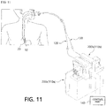
- the power transmission system 100 for driving a robot joint described above may constitute an endoscopic surgery system, and in the power transmission system 100 for driving a robot joint, the cable driving apparatus 200 for driving a robot joint may be provided as the driving unit.
- a power transmission system 100 for driving a robot joint may include a first driving unit 110a, a second driving unit 110b, a first force transmission part 120 including a first sheath 121 and a first wire 122, and a second force transmission part 130 including a second sheath 131 and a second wire 132, and the cable driving apparatus 200 for driving a robot joint described above may be provided as each of the first driving unit 110a and the second driving unit 110b.
- the first force transmission part 120 including the first sheath 121 and the first wire 122 and the second force transmission part 130 including the second sheath 131 and the second wire 132 may be employed without change, and the cable driving apparatus 200 for driving a robot joint described above may be employed as the cable driving apparatus 200 for driving a robot joint without change. Accordingly, detailed descriptions thereof will be omitted.
- the first force transmission part 120 and the second force transmission part 130 may be inserted into a protection tube 20 intubated into a patient's body through a patient's mouth, one end of the first wire 122 may be connected to a driving joint of a robot which is a control target object 10, the other end of the first wire 122 may be fixed to a wire holder 160 provided in a first cable driving apparatus 200a for driving a robot joint, one end of the second wire 132 may be connected to target object 10 of the robot, the other end of the second wire 132 may be fixed to a wire holder 160 provided in a second cable driving apparatus 200b for driving a robot joint.
- an endoscope may be fixed to the driving joint of the robot which is the control target object 10.
- an operator may operate the first cable driving apparatus 200a for driving a robot joint and the second cable driving apparatus 200b for driving a robot joint using a control part 140 to push the second wire 132 while pulling the first wire 122 or to push the first wire 122 while pulling the second wire 132.
- the driving joint of the robot which is the control target object 10 may exactly move to a position in a direction desired by the operator, and the endoscope fixed to the control target object 10 may also exactly move to a position in a direction desired by the operator, the accuracy of a procedure can be improved.
- the wire holder 160 and a sheath holder 150 may be detachably installed in a first accommodation groove 232 and a second accommodation groove 242, respectively, the wire holder 160 and the sheath holder 150 together with the first force transmission part 120 and the second force transmission part 130 may be simply removed and replaced with unused products, and the first cable driving apparatus 200a for driving a robot joint and the second cable driving apparatus 200b for driving a robot joint which provide driving forces may be simply reused without risk of contamination.
- the endoscopic surgery system is illustrated, but the present invention is not limited thereto, may be applied to any robot arm performing grip work or any driving joint of a robot for driving an robot arm, and may be widely applied to medical, household, and industrial fields, and the like.
- FIG. 12 is a schematic view illustrating a power transmission system for driving a robot joint according to another embodiment of the present invention
- FIG. 13 is a view illustrating an operation state of that of FIG. 12 .
- a power transmission system 300 for driving a robot joint realizes a double input sheath-tendon power transmission mechanism and includes a body part 310, a driving part including a first driving unit 360 and a second driving unit 370, a first force transmission part 320, a second force transmission part 330, a first elastic part 340, and a second elastic part 350.
- the body part 310 may accommodate the first driving unit 360, the second driving unit 370, the first elastic part 340, and the second elastic part 350.
- the body part 310 may be formed of a plastic or metal material or one of various materials having corrosion resistance while having rigidity.
- the first driving unit 360 may be disposed in the body part 310.
- the first driving unit 360 may include a first driving motor 361 and a first moving part 362.
- the first driving motor 361 may be installed in the body part 310.
- the first driving motor 361 may receive power to generate a driving force.
- the first moving part 362 may receive the driving force of the first driving motor 361 to move linearly.
- the first moving part 362 may be moved in a first direction 1 or second direction 2, which is opposite to the first direction 1, by the driving force of the first driving motor 361.
- the body part 310 may include a first guide hole 312 which guides the first moving part 362.
- the first moving part 362 may move along the first guide hole 312 in the first direction 1 or second direction 2.
- the second driving unit 370 may be disposed in the body part 310.
- the second driving unit 370 may include a second driving motor 371 and a second moving part 372.
- the second driving motor 371 may be installed in the body part 310.
- the second driving motor 371 may receive power to generate a driving force.
- the second moving part 372 may receive the driving force of the second driving motor 371 to move linearly.
- the second moving part 372 may be moved in the first direction 1 or second direction 2, which is opposite to the first direction 1, by the driving force of the second driving motor 371.
- the body part 310 may include a second guide hole 313 which guides the second moving part 372.
- the second guide hole 313 may be formed to be parallel to the first guide hole 312.
- the second moving part 372 may move along the second guide hole 313 in the first direction 1 or second direction 2.
- a sheath-tendon mechanism in which a tendon is inserted into a sheath to be moved in a longitudinal direction therein may be employed.
- the first force transmission part 320 may include a first sheath 321 and a first wire 322.
- the first sheath 321 may be formed to have a predetermined length, flexibility, and a hollow shape.
- the first wire 322 may be inserted into the first sheath 321.
- the first wire 322 may be inserted into the first sheath 321 so that both end portions of the first wire 322 are exposed to the outside of the first sheath 321.
- One end of both of the end portions of the first wire 322 may be fixed to a joint 10 of a robot.
- the other end of both of the end portions of the first wire 322 may pass through one side 311 of the body part 310 and may be fixed to the first moving part 362 of the first driving unit 360.
- the second force transmission part 330 may include a second sheath 331 and a second wire 332.
- the second sheath 331 may be formed to have a predetermined length, flexibility, and a hollow shape.
- the second wire 332 may be inserted into the second sheath 331.
- the second wire 332 may be inserted into the second sheath 331 so that both end portions of the second wire 332 are exposed to the outside of the second sheath 331.
- One end of both of the end portions of the second wire 332 may be fixed to the joint 10 of the robot.
- the other end of both of the end portions of the second wire 332 may pass through the one side 311 of the body part 310 and may be fixed to the second moving part 372 of the second driving unit 370.
- a first wire hole through which the first wire 322 passes and a second wire hole through which the second wire 332 passes may be formed in the one side 311 of the body part 310.
- the joint 10 of the robot may be a driving joint for driving a finger or wrist of a robot arm in a robot.
- each of the first sheath 321 and the second sheath 331 may be a coil shaped tube formed of a metal material to withstand tension applied to each of the first wire 322 and the second wire 332, to maintain an overall shape, and to have flexibility.
- the shape and the material of each of the first sheath 321 and the second sheath 331 are not limited thereto, and any shape and any material employed for a sheath in a known sheath-tendon mechanism may be applied thereto.
- the power transmission system 300 for driving a robot joint may further include a control part for controlling overall operations of the first driving unit 360 and the second driving unit 370, and the control part may control driving of the first driving unit 360 and the second driving unit 370 on the basis of an input signal of a user.
- the control part may control a magnitude of a force provided to the first wire 322 from the first driving unit 360 and a magnitude of a force provided to the second wire 332 from the second driving unit 370 on the basis of the input signal of the user.
- the control part may control the first driving unit 360 to provide a force to the first wire 322 in the first direction 1 and control the second driving unit 370 to provide a force to the second wire 332 in the second direction 2.
- first force transmission part 320 and the second force transmission part 330 may be connected to each other by the joint 10 of the robot, and in a case in which a driving force is provided to the first wire 322 from the first driving unit 360, or a driving force is provided to the second wire 332 from the second driving unit 370 through control of the control part, the first wire 322 and the second wire 332 may be respectively moved in the first sheath 321 and the second sheath 331 in longitudinal directions. Accordingly, the joint 10 of the robot may be rotated or moved to a position desired by the user.
- the first driving unit 360 and the second driving unit 370 may provide a driving force to the first force transmission part 320 and provide a driving force to the second force transmission part 330, respectively, at the same time, and a magnitude of the driving force provided to the first force transmission part 320 from the first driving unit 360 and a magnitude of the driving force provided to the second force transmission part 330 from the second driving unit 370 may be controlled by the control part.
- the second driving unit 370 may provide a force to the second wire 332 in the second direction 2.
- the first driving unit 360 may provide a force to the first wire 322.
- a role of a master cable and a role of a slave cable may be interchanged according to a direction of a force provided from the first driving unit 360 and a direction of a force provided from the second driving unit 370. That is, in a case in which the first wire 322 is moved by a first length a in the first direction 1, and the second wire 332 is moved by the first length a in the second direction 2, the first wire 322 may serve as the master cable, and the second wire 332 may serve as the slave cable.
- the second wire 332 may serve as the master cable, and the first wire 322 may serve as the slave cable.
- the power transmission system 300 for driving a robot joint by providing a pulling force to the wire serving as the master cable using the driving unit and providing an actively pushing force to the wire serving as the slave cable using the driving unit at the same time, a friction force generated due to contact between the wire and the sheath in a process in which the wire serving as the slave cable moves in the sheath may be compensated for. Accordingly, in the power transmission system 300 for driving a robot joint according to another embodiment of the present invention, even when the wire serving as the master cable is pulled using a small force, target object 10 of the robot may be moved to a desired position.
- the joint 10 of the robot may be moved to a position desired by a worker.
- the power transmission system 300 for driving a robot joint As described above, in the power transmission system 300 for driving a robot joint according to another embodiment of the present invention, as a driving force, which actively pushes the wire, is provided to the wire serving as the slave cable using the driving unit to cancel a friction force generated between the wire serving as the slave cable and the sheath, even when a small magnitude of a driving force is provided to the wire serving as the master cable, a power transmission amount at a level which is greater than or equal to that in a conventional case can be obtained.
- the first elastic part 340 may wrap the other end of the first wire 322.
- the other end of the first wire 322 may be a portion, which is disposed in the body part 310, of an entire portion of the first wire 322.
- One end of the first elastic part 340 may be fixed to an inner surface of the body part 310, and the other end of the first elastic part 340 may be fixed to the first moving part 362 of the first driving unit 360.
- the first elastic part 340 may be formed in a tube shape.
- the first elastic part 340 may be formed of one of various materials having elasticity while maintaining substantially a tube shape.
- the first elastic part 340 may contract, and as the first moving part 362 moves in the second direction 2, the first elastic part 340 may extend. Even when the first wire 322 is moved in the first direction 1 or second direction 2 by the first moving part 362, a state in which the first elastic part 340 wraps the first wire 322 may be maintained. Accordingly, the first elastic part 340 may prevent the first wire 322 from being loosened in the body part 310.
- the second elastic part 350 may wrap the second wire 332 disposed in the body part 310.
- One end of the second elastic part 350 may be fixed to the inner surface of the body part 310, and the other end of the second elastic part 350 may be fixed to the second moving part 372 of the second driving unit 370.
- the second elastic part 350 may be formed in a tube shape.
- the second elastic part 350 may be formed of one of various materials having elasticity while maintaining substantially a tube shape.
- the second elastic part 350 may be disposed to be parallel to the first elastic part 340.
- the second elastic part 350 may contract, and as the second moving part 372 moves in the second direction 2, the second elastic part 350 may extend. Even when the second wire 332 is moved in the first direction 1 or second direction 2 by the second moving part 372, a state in which the second elastic part 350 wraps the second wire 332 may be maintained. Accordingly, the second elastic part 350 may prevent the second wire 332 from being loosened in the body part 310.
- FIG. 14 is a perspective view illustrating a cartridge type power transmission system for driving a robot joint according to still another embodiment of the present invention
- FIG. 15 is a schematic perspective view illustrating a structure of the cartridge type power transmission system for driving a robot joint according to still another embodiment of the present invention
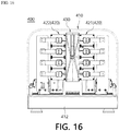
- FIG. 16 is a schematic front view illustrating the structure of the cartridge type power transmission system for driving a robot joint according to still another embodiment of the present invention
- FIG. 17 is a schematic plan view illustrating the structure of the cartridge type power transmission system for driving a robot joint according to still another embodiment of the present invention
- FIG. 18 is a schematic side view illustrating the structure of the cartridge type power transmission system for driving a robot joint according to still another embodiment of the present invention.
- a cartridge type power transmission system 400 for driving a robot joint may include a housing 410, a first driving part 420, and a cartridge 430.
- the housing 410 may accommodate the first driving part 420, the cartridge 430, and the second driving part 440 which will be described below.
- the housing 410 may be formed of a plastic or metal material.
- the housing 410 is not limited to being formed of the plastic or metal material and may be formed of one of various material having corrosion resistance while having rigidity.
- An insertion hole 411a through which the cartridge 430 is inserted into the housing 410 may be formed in one side 411 of the housing 410.
- a display which displays a state of the cartridge type power transmission system 400 for driving a robot joint, may be disposed on the one side 411 of the housing 410.
- the first driving part 420 may be disposed in the housing 410.
- the first driving part 420 may move linearly in a first direction 1 (see FIG. 13 ) or second direction 2 (see FIG. 13 ).
- the first driving part 420 may be provided as a plurality of first driving parts 420.
- the plurality of first driving parts 420 may include one first driving part 421 of the plurality of first driving parts facing one side surface of the cartridge 430 and another first driving part 422 of the plurality of first driving parts facing the other side surface of the cartridge 430.
- the another first driving part 422 of the plurality of first driving parts may be symmetrically disposed with respect to the one first driving part 421 of the plurality of first driving parts with the cartridge 430 interposed therebetween.
- the one first driving part 421 of the plurality of first driving parts may be provided as four first driving parts 421, and the another first driving part 422 of the plurality of first driving parts may be provided as four first driving parts 422.
- one first driving part 421 of the plurality of first driving parts and the another first driving part 422 of the plurality of first driving parts are not limited to being provided as four first driving parts 421 and four first driving parts 422, respectively, and the number thereof may vary to be two or six.
- the first driving part 420 will be described with reference to the drawings below.
- the cartridge 430 may be inserted into the housing 410 through the insertion hole 411a.
- the cartridge 430 may include force transmission parts 439 (see FIG. 21 ) and elastic parts 438 for implementing a double input sheath-tendon power transmission mechanism.
- the cartridge 430 will be described with reference to the drawings below.
- the cartridge type power transmission system 400 for driving a robot joint may further include a second driving part 440.
- the second driving part 440 may move the first driving part 420 in a third direction 3 or fourth direction 4, which is opposite to the third direction 3, so that the first driving part 420 is connected to or separated from the cartridge 430.
- the third direction 3 may be a direction perpendicular to a first direction 1.
- the second driving part 440 may be provided as a plurality of second driving parts 440.
- the plurality of second driving parts 440 may include one second driving part 441, which is disposed at a side opposite to the cartridge 430 with the one first driving part 421 of the plurality of first driving parts interposed between the one second driving part 441 and the cartridge 430, of the plurality of second driving parts and another second driving part 442, which is disposed at a side opposite to the cartridge 430 with the another first driving part 422 of the plurality of first driving parts interposed between the another second driving part 442 and the cartridge 430, of the plurality of second driving parts.
- the one second driving part 441 of the plurality of second driving parts may include a second motor 441a and a connection part 441b.
- the second motor 441a may be disposed on a lower surface 412 of the housing 410.
- the connection part 441b may be connected to the second motor 441a and moved linearly in the third direction 3 or fourth direction 4 by a driving force of the second motor 441a.
- the connection part 441b may be connected to the one first driving part 421 of the plurality of first driving parts.
- the one second driving part 441 of the plurality of second driving parts may move the one first driving part 421 of the plurality of first driving parts in the fourth direction 4 to connect the one first driving part 421 of the plurality of first driving parts to the cartridge 430.
- the one second driving part 441 of the plurality of second driving parts may move the one first driving part 421 of the plurality of first driving parts in the third direction 3 to separate the one first driving part 421 of the plurality of first driving parts from the cartridge 430.
- the another second driving part 442 of the plurality of second driving parts may include a second motor 442a and a connection part 442b.
- the second motor 442a may be disposed on the lower surface 412 of the housing 410.
- the connection part 442b may be connected to the second motor 442a and moved linearly in the third direction 3 or fourth direction 4 by a driving force of the second motor 442a.
- the connection part 442b may be connected to the another first driving part 422 of the plurality of first driving parts.
- the another second driving part 442 of the plurality of second driving parts may move the another first driving part 422 of the plurality of first driving parts in the third direction 3 to connect the another first driving part 422 of the plurality of first driving parts to the cartridge 430.
- the another second driving part 442 of the plurality of second driving parts may move the another first driving part 422 of the plurality of first driving parts in the fourth direction 4 to separate the another first driving part 422 of the plurality of first driving parts from the cartridge 430.
- the second driving part 440 may control whether the first driving part 420 is connected to the cartridge 430.
- the one second driving part 441 of the plurality of second driving parts and the another second driving part 442 of the plurality of second driving parts may be driven at the same time.
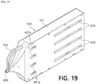
- FIG. 19 is a perspective view illustrating the cartridge of the cartridge type power transmission system for driving a robot joint according to still another embodiment of the present invention
- FIG. 20 is a side view illustrating the cartridge of the cartridge type power transmission system for driving a robot joint according to still another embodiment of the present invention
- FIG. 21 is a schematic view illustrating a structure of the cartridge of the cartridge type power transmission system for driving a robot joint according to still another embodiment of the present invention
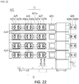
- FIG. 22 is a side view illustrating the first driving part of the cartridge type power transmission system for driving a robot joint according to still another embodiment of the present invention.
- the cartridge 430 of the the cartridge type power transmission system for driving a robot joint may include a case 431, moving parts 435, 436, and 437, the force transmission parts 439, and the elastic parts 438.
- the case 431 may accommodate the moving parts 435, 436, and 437, the force transmission parts 439, and the elastic parts 438.
- the case 431 may be formed of a plastic or metal material.
- the case 431 is not limited to being formed in the plastic or metal materials and may be formed of one of various materials having corrosion resistance while having rigidity.
- the case 431 may include a handle part 432 gripped by a hand of a user or a tool.
- the case 431 may include a guide hole 434 which guides the moving parts 435, 436, and 437.
- the guide hole 434 may be formed in a slit shape.
- the guide hole 434 may be provided as a plurality of guide holes 434.
- the plurality of guide holes 434 may be formed to be parallel to each other.
- the moving parts 435, 436, and 437 may be accommodated in the case 431.
- the moving parts 435, 436, and 437 may be connected to the first driving part 420.
- the moving parts 435, 436, and 437 may receive a driving force of the first driving part 420 to be moved linearly in a first direction 1 or second direction 2.
- the moving parts 435, 436, and 437 may be exposed to the outside of the case 431 through the guide holes 434.
- the moving parts 435, 436, and 437 may include a first moving part 435, a second moving part 436, and a third moving part 437.
- the first moving part 435, the second moving part 436, and the third moving part 437 may be arranged to be parallel to each other.
- the force transmission parts 439 may include sheaths 439a and wires 439b.
- the sheath 439a may be formed to have a predetermined length, flexibility, and a hollow shape. One portion of the sheath 439a may be accommodated in the case 431, and the other portion of the sheath 439a may be exposed to the outside of the case 431.
- sheath 439a may be similar to or the same as each of the first sheath 321 and the second sheath 331 of the embodiment described above.
- the wire 439b may be inserted into the sheath 439a.
- One end of the wire 439b may be fixed to a joint 10 of a robot (see FIG. 12 ), and the other end of the wire 439b may be fixed to the first moving part 435.
- the other end of the wire 439b may be moved in the first direction 1 or second direction 2 by movement of the first moving part 435.
- wire 439b may be the same as or similar to each of the first wire 322 and the second wire 332 of the embodiment described above.
- the elastic part 438 may be disposed in the case 431. One end of the elastic part 438 may be fixed to the case 431, and the other end of the elastic part 438 may be fixed to the first moving part 435. The elastic part 438 may extend in the first direction 1 or contract in the second direction 2 by movement of the first moving part 435.
- the elastic part 438 may be fixed to the second moving part 436 and the third moving part 437. In addition, according to still another embodiment of the present invention, the elastic part 438 may pass through the second moving part 436 and the third moving part 437.
- the elastic part 438 may be the same as or similar to the elastic part 438 of the embodiment described above.
- the first driving part 421 of the cartridge type power transmission system for driving a robot joint may include driving body parts 421a, first motors 423, and detachable parts 425, 426, and 427.
- the driving body part 421a may be moved in the third direction 3 or fourth direction 4 in the housing 410 (see FIG. 16 ) by a driving force of the second driving part 440.
- the driving body part 421a may be coupled to the connection part 441b (see FIG. 17 ) of the second driving part 440.
- the first motor 423 may be disposed on the driving body part 421a.
- the detachable parts 425, 426, and 427 may be disposed on the driving body part 421a.
- the detachable parts 425, 426, and 427 may be connected to the first motor 423.
- the detachable parts 425, 426, and 427 may be moved linearly in the first direction 1 or second direction 2 by a driving force of the first motor 423.
- the detachable parts 425, 426, and 427 may be detachably coupled to the moving parts 435, 436, and 437.
- the detachable parts 425, 426, and 427 may include protrusions 425a, 425b, 426a, 426b, 427a, and 427b protruding from outer surfaces of the detachable parts 425, 426, and 427.
- the moving parts 435, 436, and 437 may include detachable grooves 435b, 436b, and 437b into which the protrusions 425a, 425b, 426a, 426b, 427a, and 427b are inserted.
- the detachable parts 425, 426, and 427 may include a first detachable part 425, a second detachable part 426, and a third detachable part 427.
- the first detachable part 425, the second detachable part 426, and the third detachable part 427 may be arranged to be parallel to each other.
- the first detachable part 425 may be detachably coupled to the first moving part 435.
- the second detachable part 426 may be detachably coupled to the second moving part 436.
- the third detachable part 427 may be detachably coupled to the third moving part 437.
- the cartridge 430 may further include first fixing parts 431b.
- the first fixing part 431b may be exposed at a side surface of the case 431 through a fixing hole 431a formed in the side surface of the case 431.
- the first driving part 420 may include second fixing parts 428.
- the second fixing part 428 may include fixing protrusions 428a and 428b.
- a fixing groove corresponding to the fixing protrusions 428a and 428b may be formed in the first fixing part 431b.
- the fixing protrusions 428a and 428b of the second fixing part 428 may be inserted into the fixing groove of the first fixing part 431b to firmly couple the first driving part 420 and the cartridge 430.
- the detachable parts 425, 426, and 427 may receive a driving force of the first motor 423 to move in the first direction 1 or second direction 2.
- the moving parts 435, 436, and 437 may move in the first direction 1 or second direction 2 with the detachable parts 425, 426, and 427.
- the wire 439b may move in the first direction 1 or second direction 2 with the moving parts 435, 436, and 437.
- the joint 10 (see FIG. 12 ) of the robot connected to the wire 439b may be driven by movement of the wire 439b.
Landscapes
- Engineering & Computer Science (AREA)
- Health & Medical Sciences (AREA)
- Robotics (AREA)
- Life Sciences & Earth Sciences (AREA)
- Surgery (AREA)
- Mechanical Engineering (AREA)
- Heart & Thoracic Surgery (AREA)
- Biomedical Technology (AREA)
- Nuclear Medicine, Radiotherapy & Molecular Imaging (AREA)
- Medical Informatics (AREA)
- Molecular Biology (AREA)
- Animal Behavior & Ethology (AREA)
- General Health & Medical Sciences (AREA)
- Public Health (AREA)
- Veterinary Medicine (AREA)
- Manipulator (AREA)
Abstract
Description
- The present invention relates to a surgical robot, and more specifically, to a power transmission system for driving a robot joint.
- Recently, as an application range of robots has been expanded in various fields such as industry and medical fields, various actuation methods are being developed. Power is transmitted using various methods using belts, chains, or wires in addition to directly attaching an actuator to a robot joint.
- Among actuation methods, the simplest method is to directly attach an actuator to a link structure, but there is a disadvantage in that the actuator is very heavy.
- To compensate for this, a double-input cable driving method in which an actuator is fixed to a floor and transmits a force using two flexible cables was proposed.
- However, in the conventional cable driving method, since the two cables are driven only in a case in which both of two motors pull the cables, one motor should provide a force capable of pulling both of the two cables, that is, a master cable and a slave cable, in order to transmit a driving force to a target object.
- Accordingly, when the two cables are driven, since each of the motors should pull the master cable using a very large force, a motor having high output power is required, and thus there is a problem of low precision.
- In addition, in the case of the conventional driving method, since the motor applies the force, which directly pulls the master cable, to the master cable, there is no big problem with the master cable, but in the slave cable which is driven by a force applied by the master cable, since a portion, which is not inserted into a sheath and is exposed to the outside, of the slave cable is loosened to be bent or to generate large back lash, there is a problem of low precision.
- Accordingly, a method of reducing back lash is required without loosening and bending a slave cable.
- In addition, since such a cable is inserted through a body part, a disposable cable, which is not reused, is used as the cable in order to prevent a patient from being infected. After the cable is used, the cable is separated from a driving apparatus and replaced with a new cable, and thus, there is an inconvenience of coupling the cable to the driving apparatus again.
- The present invention is directed to providing a power transmission system for driving a robot joint capable of controlling movement of a slave cable to increase a power transmission amount and improve control precision.
- In addition, the present invention is directed to providing a cartridge type power transmission system for driving a robot joint which allows a disposable cable to be conveniently replaced.
- Objectives of the present invention are not limited to the objectives described above, and the other objectives, which are not described above, will be clearly understood by those skilled in the art from the following descriptions.
- One aspect of the present invention provides a power transmission system for driving a robot joint, which is a system for driving a joint of a robot, the power transmission system including a driving part including a first driving unit and a second driving unit, a first force transmission part including a first sheath formed to have a predetermined length, flexibility, and a hollow shape and a first wire which is inserted into the first sheath and of which one end is fixed to a joint of a robot and the other end is connected to the first driving unit, and a second force transmission part including a second sheath formed to have a predetermined length, flexibility, and a hollow shape and a second wire which is inserted into the second sheath and of which one end is fixed to the joint of the robot and the other end is connected to the second driving unit, wherein, in a case in which the first driving unit provides a force to the first wire in a first direction, the second driving unit provides a force to the second wire in a second direction opposite to the first direction.
- In a case in which the first driving unit applies a force to the first wire in a direction in which the first wire is pulled, the second driving unit may provide a force to the second wire in a direction in which the second wire is pushed, and in a case in which the second driving unit applies a force to the second wire in a direction in which the second wire is pulled, the first driving unit may provide a force to the first wire in a direction in which the first wire is pushed.
- In a case in which the first driving unit provides a force to the first wire in a direction in which the first wire is pulled, and the second driving unit provides a force to the second wire in a direction in which the second wire is pushed, a magnitude of the force provided to the second wire by the second driving unit may be adjusted according to a friction force generated between the second wire and the second sheath.
- A magnitude of a maximum force provided to the second wire by the second driving unit may be the same as a magnitude of the friction force generated between the second wire and the second sheath.
- In a case in which the first driving unit provides a force to the first wire in a direction in which the first wire is pulled and the second driving unit provides a force to the second wire in a direction in which the second wire is pushed, a magnitude of the force provided to the first wire by the first driving unit may be the same as a sum of a magnitude of a friction force generated between the first wire and the first sheath and a magnitude of a force which moves the joint of the robot
- In a case in which the first driving unit provides a force to the first wire in a direction in which the first wire is pulled and the second driving unit provides a force to the second wire in a direction in which the second wire is pushed, a withdrawal length of the first wire withdrawn from an outer side of an end portion of the first sheath may be relatively greater than an insertion length of the second wire inserted into the second sheath from an end portion of the second sheath.
- In the case in which the first driving unit provides the force to the first wire in the direction in which the first wire is pulled and the second driving unit provides the force to the second wire in the direction in which the second wire is pushed, a partial length, which includes the end portion of the second sheath into which the second wire is inserted, of an entire length of the second sheath may be in a state in which movement of the partial length is prevented with the second wire.
- In addition, in a case in which the first driving unit, to which the other end portion of the first wire having one end fixed to the robot joint and inserted into the first sheath is connected and which provides a force that pulls or pushes the first wire in a longitudinal direction of the first sheath, and the second driving unit, to which the other end portion of the second wire having one end fixed to the robot joint and inserted into the second sheath is connected and which provides a force that pulls or pushes the second wire in a longitudinal direction of the second sheath are included, when the first driving unit provides a force to the first wire in the first direction, a power transmission method of driving a robot joint may be provided as a cable power transmission method of driving a joint of a robot, wherein the method may include providing a force to the second wire using the second driving unit in the second direction opposite to the first direction.
- The power transmission system for driving a robot joint may further include a body part, a first elastic part of which one end is fixed to the body part and the other end is fixed to the first driving unit and which wraps the other end of the first wire, and a second elastic part of which one end is fixed to the body part and the other end is fixed to the second driving unit and which wraps the other end of the second wire, wherein the first driving unit and the second driving unit may move linearly.
- The power transmission system for driving a robot joint may further include a control part disposed in the body part, wherein the control part may control the first driving unit to provide the force to the first wire in the first direction and control the second driving unit to provide the force to the second wire in the second direction opposite to the first direction.
- A first wire hole through which the first wire passes and a second wire hole through which the second wire passes may be formed in one side of the body part.
- The first driving unit may include a first driving motor which generates a driving force and a first moving part which receives the driving force of the first driving motor to move linearly, and the second driving unit may include a second driving motor which generates a driving force and a second moving part which receives the driving force of the second driving motor to move linearly.
- The body part may include a first guide hole which guides the first moving part, and a second guide hole which guides the second moving part.
- Each of the first elastic part and the second elastic part receives a force in the first direction to contract and receives a force in the second direction to extend.
- In addition, another aspect of the present invention provides a cartridge type power transmission system for driving a robot joint, which is a power transmission system for driving a joint of a robot, the cartridge type power transmission system including a housing, a first driving part disposed in the housing and moved linearly, and a cartridge inserted into the housing, wherein the cartridge includes a case, a moving part accommodated in the case, connected to the first driving part, and moved linearly, a force transmission part including a sheath formed to have a predetermined length, flexibility, and a hollow shape and a wire which is inserted into the sheath, of which one end is fixed to a joint of a robot and the other end is fixed to the moving part, and which passes through the case, and an elastic part of which one end is fixed to the case and the other end is fixed to the moving part and which wraps the wire, and the cartridge is detachably coupled to the housing.
- The cartridge type power transmission system may further include a second driving part which moves the first driving part so that the first driving part is connected to or separated from the moving part.
- The first driving part may include a driving body part which is movable in the housing, a first motor disposed in the driving body part, and a detachable part connected to the first motor, moved linearly by a driving force of the first motor, and detachably coupled to the moving part.
- The second driving part may include a second motor disposed in the housing, and a connection part connected to the second motor and moved linearly by a driving force of the second motor.
- The detachable part may include a protrusion protruding from an outer surface of the detachable part, and the moving part may include a detachable groove into which the protrusion of the detachable part is inserted.
- The cartridge may include a hole through which the force transmission part passes.
- The case may include a guide hole which guides movement of the moving part.
- The elastic part may extend in a first direction and contract in a second direction opposite to the first direction.
- According to an embodiment of the present invention, since a driving unit provides a driving force to a slave cable to cancel a friction force generated by the slave cable, even when a driving force having a small magnitude is provided to a master cable, a power transmission amount at a level which is greater than or equal to that in a conventional case can be obtained.
- In addition, according to the embodiment of the present invention, since a friction force generated by the slave cable is canceled to prevent or reduce back lash at the slave cable, there is an advantage of improving control precision.
- In addition, since a cartridge including the cable is detachably coupled to a housing, the cable used in surgery can be easily replaced.
- In addition, since the cable is driven by the cartridge being inserted into the housing, hygiene management of a surgical robot driving apparatus is improved when compared to a conventional case in which there is an infection risk in a process of connecting a cable to a driving apparatus.
-
-
FIG. 1 is a schematic view illustrating a power transmission system for driving a robot joint according to one embodiment of the present invention. -
FIG. 2 is a view illustrating an operation state of that ofFIG. 1 . -
FIG. 3 is an enlarged view illustrating a portion A inFIG. 2 . -
FIG. 4 is a view illustrating an operation state of a case in which a driving unit excessively provides a pushing force to a wire inFIG. 1 . -
FIG. 5 is a view illustrating a cable driving apparatus for driving a robot joint which may be employed as a driving unit in the power transmission system for driving a robot joint according to one embodiment of the present invention. -
FIG. 6 is an exploded view illustrating main components inFIG. 5 . -
FIG. 7 is a view illustratingFIG. 6 when viewed from another side. -
FIG. 8 is a partial cross-sectional view illustrating a state in which a wire is wound around a roller inFIG. 6 . -
FIG. 9 is a view illustrating an operation state of a case in which a motor pulls the wire inFIG. 8 . -
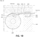
FIG. 10 is a view illustrating an operation state of a case in which the motor pushes the wire inFIG. 8 . -
FIG. 11 is a schematic view illustrating a state in which the power transmission system for driving a robot joint according to one embodiment of the present invention is applied to an endoscopic surgery system. -
FIG. 12 is a schematic view illustrating a power transmission system for driving a robot joint according to another embodiment of the present invention. -
FIG. 13 is a view illustrating an operation state of that ofFIG. 12 . -
FIG. 14 is a perspective view illustrating a cartridge type power transmission system for driving a robot joint according to still another embodiment of the present invention. -
FIG. 15 is a schematic perspective view illustrating a structure of the cartridge type power transmission system for driving a robot joint according to still another embodiment of the present invention. -
FIG. 16 is a schematic front view illustrating the structure of the cartridge type power transmission system for driving a robot joint according to still another embodiment of the present invention. -
FIG. 17 is a schematic plan view illustrating the structure of the power transmission system for driving a robot joint according to still another embodiment of the present invention. -
FIG. 18 is a schematic side view illustrating the structure of the power transmission system for driving a robot joint according to still another embodiment of the present invention. -
FIG. 19 is a perspective view illustrating a cartridge of the cartridge type power transmission system for driving a robot joint according to still another embodiment of the present invention. -
FIG. 20 is a side view illustrating the cartridge of the cartridge type power transmission system for driving a robot joint according to still another embodiment of the present invention. -
FIG. 21 is a schematic view illustrating a structure of the cartridge of the cartridge type power transmission system for driving a robot joint according to still another embodiment of the present invention. -
FIG. 22 is a side view illustrating a first driving part of the cartridge type power transmission system for driving a robot joint according to still another embodiment of the present invention. -
- 100:
- POWER TRANSMISSION SYSTEM FOR DRIVING ROBOT JOINT
110A: FIRST DRIVING UNIT
112A: FIRST DRIVING MOTOR
114A: FIRST ROLLER
110B: SECOND DRIVING UNIT
112B: SECOND DRIVING MOTOR
114B: SECOND ROLLER - 120:
- FIRST FORCE TRANSMISSION PART
- 121:
- FIRST SHEATH
- 122:
- FIRST WIRE
- 130:
- SECOND FORCE TRANSMISSION PART
- 131:
- SECOND SHEATH
- 132:
- SECOND WIRE
- 140:
- CONTROL PART
- 150:
- SHEATH HOLDER
- 160:
- WIRE HOLDER
- 200, 200A, 200B:
- CABLE DRIVING APPARATUS FOR DRIVING ROBOT JOINT
- 210:
- MAIN BODY
- 212:
- ARRANGEMENT HOLE
- 220:
- DRIVING MOTOR
- 230:
- DRIVING ROLLER
- 232:
- FIRST ACCOMMODATION GROOVE
- 234:
- SEATING GROOVE
- 240:
- WEIGHT MEASUREMENT PART
- 242:
- SECOND ACCOMMODATION GROOVE
- 250:
- COVER
- 251:
- COVER SURFACE
- 252:
- GUIDE GROOVE
- 252A:
- FIRST GUIDE GROOVE
- 252B:
- SECOND GUIDE GROOVE
- 300:
- POWER TRANSMISSION SYSTEM FOR DRIVING ROBOT JOINT
- 310:
- BODY PART
- 361:
- FIRST DRIVING UNIT
- 371:
- SECOND DRIVING UNIT
- 320:
- FIRST FORCE TRANSMISSION PART
- 321:
- FIRST SHEATH
- 322:
- FIRST WIRE
- 330:
- SECOND FORCE TRANSMISSION PART
- 331:
- SECOND SHEATH
- 332:
- SECOND WIRE
- 340:
- FIRST ELASTIC PART
- 350:
- SECOND ELASTIC PART
- 400:
- CARTRIDGE TYPE POWER TRANSMISSION SYSTEM FOR DRIVING ROBOT JOINT
- 410:
- HOUSING
- 420:
- FIRST DRIVING PART
- 430:
- CARTRIDGE
- Hereinafter, various embodiments will be described in detail with reference to the accompanying drawings. The embodiments according to the present invention may be variously changed. Specific embodiments may be illustrated in the drawings and described in detail in the modes of the invention. However, the accompanying specific embodiments are only for various embodiments to be easily understood. Accordingly, the technical spirit is not limited to the specific embodiments illustrated in the accompanying drawings and should be understood to cover all modifications, equivalents, and alternatives falling within the spirit and scope of the invention.
- Although the terms "first," "second," and the like may be used herein to describe various elements, these elements should not be limited by these terms. These terms are only used for distinguishing one element from another.
- It should be understood that the terms "comprises," "comprising," "includes," and/or "including," in the embodiment of the present invention, specify the presence of stated features, integers, steps, operations, elements, components, and/or groups thereof but do not preclude the presence or addition of one or more other features, integers, steps, operations, elements, components, and/or groups thereof. In the present specification, when an element is referred to as being "connected" or "coupled" to another element, it will be understood that the element can be directly connected or coupled to another element, or intervening elements may be present therebetween. In contrast, when an element is referred to as being "directly connected" or "directly coupled" to another element, it will be understood there are no intervening elements.
- Meanwhile, a "module" or "part" among components used in the embodiment performs at least one function or operation. In addition, the "module" or "part" may perform the function or operation using hardware, software, or combination thereof. In addition, a plurality of "modules" or "parts" excluding a "module" or "part" which should be performed by specific hardware or at least one processor may also be integrated as at least one module. The description of a singular form in the present specification includes a description of a plural form unless the context clearly indicates otherwise.
- In addition, when the embodiments of the present invention are described, in a case in which it is determined that the detailed descriptions may unnecessarily obscure the gist of the present invention, the detailed descriptions of known functions and configurations related to the present invention will be reduced or omitted.
- A
power transmission system 100 for driving a robot joint according to one embodiment of the present invention realizes a double input sheath-tendon power transmission mechanism and includes a driving part, a firstforce transmission part 120, and a secondforce transmission part 130 as illustrated inFIGS. 1 and2 . - That is, in the
power transmission system 100 for driving a robot joint according to one embodiment of the present invention, the driving part may include afirst driving unit 110a and asecond driving unit 110b, thefirst driving unit 110a may be directly connected to the firstforce transmission part 120 and may provide a driving force to the firstforce transmission part 120, and thesecond driving unit 110b may be directly connected to the secondforce transmission part 130 and may provide a driving force to the secondforce transmission part 130. - In the present invention, in each of the first
force transmission part 120 and the secondforce transmission part 130, a sheath-tendon mechanism in which a tendon is inserted into a sheath to be moved in a longitudinal direction therein may be employed. - That is, the first
force transmission part 120 may include afirst sheath 121 having a predetermined length, flexibility, and a hollow shape and afirst wire 122 inserted into thefirst sheath 121. In this case, thefirst wire 122 may be inserted into thefirst sheath 121 so that both end portions of thefirst wire 122 are exposed to the outside of thefirst sheath 121, one end portion of both of the end portions, which are exposed to the outside, of thefirst wire 122 may be fixed to acontrol target object 10, and the other end portion thereof may be fixed to thefirst driving unit 110a. - Similarly, the second
force transmission part 130 may include asecond sheath 131 having a predetermined length, flexibility, and a hollow shape and asecond wire 132 inserted into thesecond sheath 131. In this case, thesecond wire 132 may be inserted into thesecond sheath 131 so that both end portions of thesecond wire 132 are exposed to the outside of thesecond sheath 131, and one end portion of both of the end portions, which are exposed to the outside, of thesecond wire 132 may be fixed to thecontrol target object 10, and the other end portion thereof may be fixed to thesecond driving unit 110b. - In addition, the
first driving unit 110a may include afirst driving motor 112a and afirst roller 114a rotatably coupled to thefirst driving motor 112a, and one end portion of thefirst wire 122 may be fixedly coupled to thefirst roller 114a. - Similarly, the
second driving unit 110b may include asecond driving motor 112b and asecond roller 114b rotatably coupled to thesecond driving motor 112b, and one end portion of thesecond wire 132 may be fixedly coupled to thesecond roller 114b. - In the present invention, the
control target object 10 may be a driving joint of a robot, and the driving joint of the robot may be a driving joint for driving a finger or a wrist of the robot in a robot arm. In addition, each of thefirst sheath 121 and thesecond sheath 131 may be a coil shaped tube formed of a metal material to withstand tension applied to each of thefirst wire 122 and thesecond wire 132, to maintain an overall shape, and to have flexibility. However, the shape and the material of each of thefirst sheath 121 and thesecond sheath 131 are not limited thereto, and any shape and any material employed for a sheath in a known sheath-tendon mechanism may be applied thereto. - In addition, the
power transmission system 100 for driving a robot joint according to one embodiment of the present invention may further include acontrol part 140 for controlling overall operations of thefirst driving unit 110a and thesecond driving unit 110b, and thecontrol part 140 may control driving of thefirst driving unit 110a and driving of thesecond driving unit 110b on the basis of an input signal of a user. In addition, thecontrol part 140 may control a magnitude of a force provided to thefirst wire 122 from thefirst driving unit 110a and a magnitude of a force provided to thesecond wire 132 from thesecond driving unit 110b on the basis of the input signal of the user. - As described above, in the
power transmission system 100 for driving a robot joint according to one embodiment of the present invention, the firstforce transmission part 120 in which the end portion of thefirst wire 122 is connected to thefirst driving unit 110a and the secondforce transmission part 130 in which the end portion of thesecond wire 132 is connected to thesecond driving unit 110b may be connected by thecontrol target object 10, and in a case in which a driving force is transmitted to thefirst wire 122 from thefirst driving unit 110a, or a driving force is transmitted to thesecond wire 132 from thesecond driving unit 110b through control of thecontrol part 140, thefirst wire 122 and thesecond wire 132 may move in the longitudinal directions in thefirst sheath 121 and thesecond sheath 131, respectively. Accordingly, thecontrol target object 10 may be rotated or moved to a position desired by the user. - In this case, in the
power transmission system 100 for driving a robot joint according to one embodiment of the present invention, unlike a conventional double input sheath-tendon mechanism, thefirst driving unit 110a and thesecond driving unit 110b may provide a driving force to the firstforce transmission part 120 and a driving force to the secondforce transmission part 130 at the same time, and a magnitude of the driving force provided to the firstforce transmission part 120 and a magnitude of the driving force provided to the secondforce transmission part 130 from thefirst driving unit 110a and thesecond driving unit 110b, respectively, may be controlled by thecontrol part 140. - That is, as illustrated in
FIGS. 2 and3 , in thepower transmission system 100 for driving a robot joint according to one embodiment of the present invention, in a case in which thefirst driving unit 110a provides a force to thefirst wire 122 in a first direction, thesecond driving unit 110b may provide a force to thesecond wire 132 in a second direction opposite to the first direction. - Similarly, in the
power transmission system 100 for driving a robot joint according to one embodiment of the present invention, in a case in which thesecond driving unit 110b provides a force to thesecond wire 132 in the first direction, thefirst driving unit 110a may provide a force to thefirst wire 122 in the second direction opposite to the first direction. - In the present invention, the first direction is defined as a direction of a force by which the
first driving unit 110a pulls thefirst wire 122 or a direction of a force by which thesecond driving unit 110b pullssecond wire 132, and the second direction is defined as a direction of a force by which thefirst driving unit 110a pushes thefirst wire 122, or a direction of a force by which thesecond driving unit 110b pushes thesecond wire 132. - In addition, in the
first wire 122 and thesecond wire 132, a role of a master cable and a role of a slave cable may be interchanged according to directions of forces provided from thefirst driving unit 110a and thesecond driving unit 110b. - That is, in a case in which the
first wire 122 moves in the first direction and thesecond wire 132 moves in the second direction, thefirst wire 122 may serve as the master cable, and thesecond wire 132 may serve as the slave cable. Conversely, in a case in which thefirst wire 122 moves in the second direction and thesecond wire 132 moves in the first direction, thesecond wire 132 may serve as the master cable, and thefirst wire 122 may serve as the slave cable. - Specifically, in a case in which the
first driving unit 110a provides a force T1 to thefirst wire 122 in the first direction, thesecond driving unit 110b may provide a force T2 to thesecond wire 132 in the second direction. Accordingly, thecontrol target object 10 connected to the end portion of thefirst wire 122 and the end portion of thesecond wire 132 may be rotated in the first direction as illustrated inFIG. 2 . - Conversely, in a case in which the
second driving unit 110b provides a force to thesecond wire 132 in the first direction, thefirst driving unit 110a may provide a force to thefirst wire 122 in the second direction. Accordingly, thecontrol target object 10 connected to the end portion of thefirst wire 122 and the end portion of thesecond wire 132 may be rotated in the second direction. - That is, in the
power transmission system 100 for driving a robot joint according to one embodiment of the present invention, in a case in which, among thefirst wire 122 andsecond wire 132, the force T1 is provided to any one wire serving as the master cable in the first direction in which the wire is pulled, the force T2 may be provided to the remaining wire serving as the slave cable in the second direction in which the wire is pushed. - In other words, in the
power transmission system 100 for driving a robot joint according to one embodiment of the present invention, by providing the force T1 which pulls the wire serving as the master cable using the driving unit and providing the force T2 which actively pushes the wire serving as the slave cable using the driving unit at the same time, a friction force T3 generated due to contact between the wires and the sheaths in a process in which the wires moved in the sheaths may be compensated for. - Accordingly, in the
power transmission system 100 for driving a robot joint according to one embodiment of the present invention, even when the wire serving as the master cable is pulled using a small force, thecontrol target object 10 may be moved to a desired position. - Hereinafter, for the sake of convenience in the description, an example, in which the
first wire 122 serves as the master cable which controls movement of thecontrol target object 10 and thesecond wire 132 serves as the slave cable role, will be described, and since an opposite case, in which thesecond wire 132 serves as the master cable which controls movement of thecontrol target object 10 and thefirst wire 122 serves as the slave cable, is the same as the example except that a magnitude and a direction of a force provided to thefirst wire 122 and a magnitude and a direction of a force provided to thesecond wire 132 are interchanged, the detailed description thereof will be omitted. - Specifically, as illustrated in
FIGS. 2 and3 , in a case in which thefirst driving unit 110a provides the force T1 to thefirst wire 122 in the first direction, thesecond driving unit 110b may provide the force T2 to thesecond wire 132 in the second direction. - In this case, a magnitude of the force T2 provided to the
second wire 132 in the second direction by thesecond driving unit 110b may be set on the basis of the friction force T3 generated between thesecond wire 132 and thesecond sheath 131 in a process in which thesecond wire 132 is moved toward thecontrol target object 10 in the longitudinal direction of thesecond sheath 131. - Preferably, the magnitude of the force T2 provided to the
second wire 132 in the second direction by thesecond driving unit 110b may be provided to be the same as a magnitude of the friction force T3 generated between thesecond wire 132 and thesecond sheath 131 in the process in which thesecond wire 132 is moved to thecontrol target object 10 in the longitudinal direction of thesecond sheath 131. - Accordingly, when a magnitude of the force T1 provided to the
first wire 122 in the first direction by thefirst driving unit 110a is the same as the sum of a magnitude of a friction force T11 generated between thefirst wire 122 and thefirst sheath 121 and a magnitude of a force T12 for moving thecontrol target object 10 in a process in which thefirst wire 122 is moved toward thefirst driving unit 110a in the longitudinal direction of thefirst sheath 121, thecontrol target object 10 may be moved to a position desired by a worker. - In this case, a magnitude of the maximum force T2 provided to the
second wire 132 in the second direction by thesecond driving unit 110b may be the same as the magnitude of the friction force T3 generated between thesecond wire 132 and thesecond sheath 131 in the process in which thesecond wire 132 is moved to thecontrol target object 10 in the longitudinal direction of thesecond sheath 131. In addition, the magnitude of the maximum force T2 provided to thesecond wire 132 in the second direction by thesecond driving unit 110b may be smaller than the magnitude of the force T1 provided to thefirst wire 122 in the first direction by thefirst driving unit 110a. - This is because, as illustrated in
FIG. 4 , when the magnitude of the maximum force T2 provided to thesecond wire 132 in the second direction by thesecond driving unit 110b is greater than the magnitude of the friction force T3 generated between thesecond wire 132 and thesecond sheath 131, a portion, which is connected to thecontrol target object 10 and exposed at an end portion of thesecond sheath 131, of thesecond wire 132 may be bent, and in a case in which the force T1 which pulls thefirst wire 122 is removed, back lash may occur at thesecond wire 132. - Meanwhile, in the
power transmission system 100 for driving a robot joint according to one embodiment of the present invention, in a case in which a force is provided to the wire serving as the slave cable, in order for the wire to not be loosened and to be smoothly move in the sheath, the end portion of the sheath may be fixed to thedriving unit - As an example, in a case in which the
first driving unit 110a provides a force to thefirst wire 122 in the first direction, and thesecond driving unit 110b provides a force to thesecond wire 132 in the second direction at the same time, a partial length B, which includes the end portion into which thesecond wire 132 is inserted, of an entire length of thesecond sheath 131 may be in a state in which movement of the partial length B is prevented with thesecond wire 132. - As a non-restrictive example, the
second sheath 131 may be fixed in a stated in which the partial length B, which includes the end portion into which thesecond wire 132 is inserted, of the entire length of thesecond sheath 131 is inserted into aguide groove 252 formed in a side of thesecond driving unit 110b in a direction parallel to the longitudinal direction, and theguide groove 252 may be formed so that a part, which is exposed to the outside, of thesecond wire 132 is seated on theguide groove 252 with the partial length B of the second sheath 131 (seeFIG. 8 ). - Accordingly, in a case in which the
second driving unit 110b provides a force to thesecond wire 132 in the second direction, since the partial length, which is exposed to the outside from the end portion of thesecond sheath 131, of thesecond wire 132 may be directly moved to thesecond sheath 131 along theguide groove 252, thesecond wire 132 can be prevented from being loosened at a side of the end portion of thesecond sheath 131. - As described above, in the
power transmission system 100 for driving a robot joint according to one embodiment of the present invention, since the driving unit provides a driving force, which actively pushes the wire serving as the slave cable, to the wire to cancel a friction force generated between the wire serving as the slave cable and the sheath, even when a small magnitude of a driving force is provided to the wire serving as the master cable, a power transmission amount at a level which is greater than or equal to that in a conventional case can be obtained. - In addition, according to the present invention, since a friction force generated by the slave cable is canceled to prevent or reduce back lash at the slave cable, there is an advantage of improving control precision.
- Meanwhile, in the
power transmission system 100 for driving a robot joint according to one embodiment of the present invention, each of thefirst driving unit 110a and thesecond driving unit 110b may be implemented as acable driving apparatus 200 for driving a robot joint. - As an example, each of the
first driving unit 110a and thesecond driving unit 110b may be thecable driving apparatus 200 for driving a robot joint illustrated inFIGS. 5 to 7 , and in thecable driving apparatus 200 for driving a robot joint, a force that pulls awire sheath wire sheath roller 230 using a drivingmotor 220 in a state in which asheath holder 150, to which thesheath wire holder 160, to which an end portion of thewire - In the present embodiment, the
sheath first sheath 121 or thesecond sheath 131 described above, and thewire first wire 122 or thesecond wire 132 described above. - In addition, in the
power transmission system 100 for driving a robot joint, thefirst driving motor 112a and thefirst roller 114a constituting thefirst driving unit 110a may be the drivingmotor 220 and the drivingroller 230, respectively, which will be described below. In addition, in thepower transmission system 100 for driving a robot joint, thesecond driving motor 112b and thesecond roller 114b constituting thesecond driving unit 110b may also be the drivingmotor 220 and the drivingroller 230, respectively, which will be described below. - In this case, the
sheath sheath holder 150 so that both end portions of thesheath sheath holder 150 by a predetermined length, thewire sheath sheath holder 150 in a state in which one end portion of thewire control target object 10, and the other end portion thereof may be fixed to thewire holder 160. - In this state, the
sheath holder 150 and thewire holder 160 may be installed in thecable driving apparatus 200 for driving a robot joint. - To this end, the
cable driving apparatus 200 for driving a robot joint according to the embodiment of the present invention may include amain body 210, the drivingmotor 220, the drivingroller 230, and aweight measurement part 240. - Specifically, the
main body 210 may serve as a fixture on which the drivingmotor 220, the drivingroller 230, and theweight measurement part 240 are installed. - As an example, the driving
motor 220 may be disposed on one surface of themain body 210, and anarrangement hole 212 having a shape corresponding to the drivingroller 230 may be formed in one surface of themain body 210 so that the drivingroller 230 may be disposed in thearrangement hole 212. - In addition, the driving
roller 230 may be driven by a driving force provided from the drivingmotor 220 and rotatably disposed in thearrangement hole 212, and afirst accommodation groove 232 for accommodating thewire holder 160 may be formed in one side of the drivingroller 230. - In this case, the driving
motor 220 may include a speed reduction device, and the drivingroller 230 may be rotatably coupled to the speed reduction device. - Accordingly, as illustrated in
FIGS. 9 and10 , in a state in which thewire holder 160 is installed in thefirst accommodation groove 232, in a case in which the drivingroller 230 rotates in one direction or the opposite direction, thewire holder 160 to which the end portion of thewire roller 230 to pull or push thewire - In this case, one side of the
arrangement hole 212 may be formed to be open so that thefirst accommodation groove 232 is exposed to the outside. Accordingly, in a case in which thefirst accommodation groove 232 is disposed to be positioned in thearrangement hole 212 formed to be open, thewire holder 160 may be easily installed in thefirst accommodation groove 232. - In addition, a
seating groove 234 recessed inward in a circumferential direction may be formed in the drivingroller 230 to accommodate a thickness of thewire wire sheath roller 230 at least one time along theseating groove 234, since the end portion of thewire wire holder 160, a force may be smoothly transmitted to thewire - In addition, even when the driving
roller 230 rotates in one direction or the opposite direction to withdraw thewire sheath wire seating groove 234 so that a winding direction of thewire wire - In this case, the driving
motor 220 may be driven in a forward or reverse direction through control of a control part, and the control part may be thecontrol part 140 described above. - The
weight measurement part 240 may be fixedly installed on one side of themain body 210, and asecond accommodation groove 242 for accommodating thesheath holder 150 may be formed in one side. That is, thesheath holder 150, to which a partial length of thesheath second accommodation groove 242. - In this case, the
weight measurement part 240 may be a load cell, and thesecond accommodation groove 242 may be directly formed in one side of the load cell or may also be formed as a separated member fixedly coupled to the load cell. - As an example, in a case in which the
sheath holder 150 is installed in thesecond accommodation groove 242, theweight measurement part 240 may be disposed on one side of the drivingroller 230 so that thewire sheath wire holder 160. - Accordingly, in a state in which the
sheath holder 150 is installed in thesecond accommodation groove 242 and thewire holder 160 is installed in thefirst accommodation groove 232, in a case in which thewire holder 160 is rotated by rotation of the drivingroller 230 to provide a force to thewire weight measurement part 240 may measure a force applied to thesheath holder 150 and may measure a force of thesheath sheath holder 150. - In this case, since the force applied to the
wire sheath wire sheath holder 150. - Accordingly, a force provided to the
wire motor 220 may be exactly controlled by control of thecontrol part 140 on the basis of a magnitude of a load applied to thesheath holder 150. - Accordingly, in the
power transmission system 100 for driving a robot joint described above, since a magnitude of a pulling force applied to the wire serving as the master cable and a magnitude of a pushing force applied to the wire serving as the slave cable may be properly controlled, a friction force generated between the wire serving as the slave cable and the sheath may be compensated for exactly. - In this case, the
cable driving apparatus 200 for driving a robot joint according to one embodiment of the present invention may include acover 250 so that, in a case in which a force is applied to thewire wire sheath motor 220, thewire sheath - That is, the
cable driving apparatus 200 for driving a robot joint according to one embodiment of the present invention may include thecover 250 having acover surface 251 which covers an upper portion of thefirst accommodation groove 232 and an upper portion of thesecond accommodation groove 242 at the same time in an initial state in which thewire holder 160 and thesheath holder 150 are respectively installed in thefirst accommodation groove 232 and thesecond accommodation groove 242, and thefirst accommodation groove 232 is positioned at an open portion of thearrangement hole 212. - Accordingly, since the
wire holder 160 and thesheath holder 150 respectively installed in thefirst accommodation groove 232 and thesecond accommodation groove 242 are pressed by thecover surface 251, thewire holder 160 and thesheath holder 150 may be prevented from being separated from thefirst accommodation groove 232 and thesecond accommodation groove 242, respectively. - The
cover 250 may also be detachably coupled to themain body 210, and alternatively, one side of thecover 250 may also be rotatably coupled to themain body 210. - In this case, as illustrated in
FIG. 7 , thecover surface 251 may include aguide groove 252 formed to be recessed so that a protruding portion B of thesheath roller 230 from thesheath holder 150 and a part of thewire sheath guide groove 252 at the same time in a state in which thesheath holder 150 is installed in thesecond accommodation groove 242. - That is, the
guide groove 252 may include afirst guide groove 252a for accommodating the protruding portion B of thesheath second guide groove 252b for accommodating thewire sheath first guide groove 252a and thesecond guide groove 252b may be formed to be connected to each other. - In addition, a bottom surface of the
first guide groove 252a and a bottom surface of thesecond guide groove 252b may be formed as a stepped surface. - Accordingly, as illustrated in
FIG. 8 , in a state in which thesheath holder 150 is installed in thesecond accommodation groove 242, the protruding portion B of thesheath sheath holder 150 toward the drivingroller 230 may be connected to an end portion of thefirst accommodation groove 232. - Accordingly, in the
cable driving apparatus 200 for driving a robot joint according to one embodiment of the present invention, even when a force is applied to thewire wire sheath motor 220, in a state in which a movement direction of thewire second guide groove 252b, since thewire sheath sheath first guide groove 252a, thewire sheath wire - Accordingly, in the
cable driving apparatus 200 for driving a robot joint according to one embodiment of the present invention, even when a force is applied to thewire wire sheath motor 220, since there is no side effect such as loss of a force or bending of a wire in a process in which thewire sheath weight measurement part 240 may exactly measure a force applied to thesheath holder 150. - As described above, in the
cable driving apparatus 200 for driving a robot joint according to one embodiment of the present invention, according to the structure described above, in a state in which thesheath holder 150 is installed in thesecond accommodation groove 242, and thewire holder 160 is installed in thefirst accommodation groove 232, a pulling force may be exactly applied to thewire wire motor 220. - Accordingly, the
cable driving apparatus 200 for driving a robot joint according to one embodiment of the present invention may be employed as thedriving unit power transmission system 100 for driving a robot joint. - Meanwhile, the
power transmission system 100 for driving a robot joint described above may constitute an endoscopic surgery system, and in thepower transmission system 100 for driving a robot joint, thecable driving apparatus 200 for driving a robot joint may be provided as the driving unit. - As an example, as illustrated in
FIG. 11 , apower transmission system 100 for driving a robot joint may include afirst driving unit 110a, asecond driving unit 110b, a firstforce transmission part 120 including afirst sheath 121 and afirst wire 122, and a secondforce transmission part 130 including asecond sheath 131 and asecond wire 132, and thecable driving apparatus 200 for driving a robot joint described above may be provided as each of thefirst driving unit 110a and thesecond driving unit 110b. - In this case, the first
force transmission part 120 including thefirst sheath 121 and thefirst wire 122 and the secondforce transmission part 130 including thesecond sheath 131 and thesecond wire 132 may be employed without change, and thecable driving apparatus 200 for driving a robot joint described above may be employed as thecable driving apparatus 200 for driving a robot joint without change. Accordingly, detailed descriptions thereof will be omitted. - In this case, the first
force transmission part 120 and the secondforce transmission part 130 may be inserted into aprotection tube 20 intubated into a patient's body through a patient's mouth, one end of thefirst wire 122 may be connected to a driving joint of a robot which is acontrol target object 10, the other end of thefirst wire 122 may be fixed to awire holder 160 provided in a firstcable driving apparatus 200a for driving a robot joint, one end of thesecond wire 132 may be connected to targetobject 10 of the robot, the other end of thesecond wire 132 may be fixed to awire holder 160 provided in a secondcable driving apparatus 200b for driving a robot joint. In this case, an endoscope may be fixed to the driving joint of the robot which is thecontrol target object 10. - In this state, an operator may operate the first
cable driving apparatus 200a for driving a robot joint and the secondcable driving apparatus 200b for driving a robot joint using acontrol part 140 to push thesecond wire 132 while pulling thefirst wire 122 or to push thefirst wire 122 while pulling thesecond wire 132. - Accordingly, since the driving joint of the robot which is the
control target object 10 may exactly move to a position in a direction desired by the operator, and the endoscope fixed to thecontrol target object 10 may also exactly move to a position in a direction desired by the operator, the accuracy of a procedure can be improved. - In addition, since the
wire holder 160 and asheath holder 150 may be detachably installed in afirst accommodation groove 232 and asecond accommodation groove 242, respectively, thewire holder 160 and thesheath holder 150 together with the firstforce transmission part 120 and the secondforce transmission part 130 may be simply removed and replaced with unused products, and the firstcable driving apparatus 200a for driving a robot joint and the secondcable driving apparatus 200b for driving a robot joint which provide driving forces may be simply reused without risk of contamination. - Meanwhile, as an example of an application to which the
power transmission system 100 for driving a robot joint or thepower transmission system 100 for driving a robot joint including thecable driving apparatus 200 for driving a robot joint is applied, the endoscopic surgery system is illustrated, but the present invention is not limited thereto, may be applied to any robot arm performing grip work or any driving joint of a robot for driving an robot arm, and may be widely applied to medical, household, and industrial fields, and the like. -
FIG. 12 is a schematic view illustrating a power transmission system for driving a robot joint according to another embodiment of the present invention, andFIG. 13 is a view illustrating an operation state of that ofFIG. 12 . - Referring to
FIGS. 12 and 13 , apower transmission system 300 for driving a robot joint according to another embodiment of the present invention realizes a double input sheath-tendon power transmission mechanism and includes abody part 310, a driving part including afirst driving unit 360 and asecond driving unit 370, a firstforce transmission part 320, a secondforce transmission part 330, a firstelastic part 340, and a secondelastic part 350. - The
body part 310 may accommodate thefirst driving unit 360, thesecond driving unit 370, the firstelastic part 340, and the secondelastic part 350. Thebody part 310 may be formed of a plastic or metal material or one of various materials having corrosion resistance while having rigidity. - The
first driving unit 360 may be disposed in thebody part 310. Thefirst driving unit 360 may include afirst driving motor 361 and a first movingpart 362. - The
first driving motor 361 may be installed in thebody part 310. Thefirst driving motor 361 may receive power to generate a driving force. - The first moving
part 362 may receive the driving force of thefirst driving motor 361 to move linearly. For example, the first movingpart 362 may be moved in afirst direction ① orsecond direction ②, which is opposite to thefirst direction ①, by the driving force of thefirst driving motor 361. - According to one embodiment of the present invention, the
body part 310 may include afirst guide hole 312 which guides the first movingpart 362. The first movingpart 362 may move along thefirst guide hole 312 in thefirst direction ① orsecond direction ②. - The
second driving unit 370 may be disposed in thebody part 310. Thesecond driving unit 370 may include asecond driving motor 371 and a second movingpart 372. - The
second driving motor 371 may be installed in thebody part 310. Thesecond driving motor 371 may receive power to generate a driving force. - The second moving
part 372 may receive the driving force of thesecond driving motor 371 to move linearly. For example, the second movingpart 372 may be moved in thefirst direction ① orsecond direction ②, which is opposite to thefirst direction ①, by the driving force of thesecond driving motor 371. - According to one embodiment of the present invention, the
body part 310 may include asecond guide hole 313 which guides the second movingpart 372. Thesecond guide hole 313 may be formed to be parallel to thefirst guide hole 312. The second movingpart 372 may move along thesecond guide hole 313 in thefirst direction ① orsecond direction ②. - In each of the first
force transmission part 320 and the secondforce transmission part 330, a sheath-tendon mechanism in which a tendon is inserted into a sheath to be moved in a longitudinal direction therein may be employed. - The first
force transmission part 320 may include afirst sheath 321 and afirst wire 322. Thefirst sheath 321 may be formed to have a predetermined length, flexibility, and a hollow shape. Thefirst wire 322 may be inserted into thefirst sheath 321. Thefirst wire 322 may be inserted into thefirst sheath 321 so that both end portions of thefirst wire 322 are exposed to the outside of thefirst sheath 321. One end of both of the end portions of thefirst wire 322 may be fixed to a joint 10 of a robot. The other end of both of the end portions of thefirst wire 322 may pass through oneside 311 of thebody part 310 and may be fixed to the first movingpart 362 of thefirst driving unit 360. - The second
force transmission part 330 may include asecond sheath 331 and asecond wire 332. Thesecond sheath 331 may be formed to have a predetermined length, flexibility, and a hollow shape. Thesecond wire 332 may be inserted into thesecond sheath 331. Thesecond wire 332 may be inserted into thesecond sheath 331 so that both end portions of thesecond wire 332 are exposed to the outside of thesecond sheath 331. One end of both of the end portions of thesecond wire 332 may be fixed to the joint 10 of the robot. The other end of both of the end portions of thesecond wire 332 may pass through the oneside 311 of thebody part 310 and may be fixed to the second movingpart 372 of thesecond driving unit 370. - According to another embodiment of the present invention, a first wire hole through which the
first wire 322 passes and a second wire hole through which thesecond wire 332 passes may be formed in the oneside 311 of thebody part 310. - According to another embodiment of the present invention, the joint 10 of the robot may be a driving joint for driving a finger or wrist of a robot arm in a robot.
- In addition, each of the
first sheath 321 and thesecond sheath 331 may be a coil shaped tube formed of a metal material to withstand tension applied to each of thefirst wire 322 and thesecond wire 332, to maintain an overall shape, and to have flexibility. However, the shape and the material of each of thefirst sheath 321 and thesecond sheath 331 are not limited thereto, and any shape and any material employed for a sheath in a known sheath-tendon mechanism may be applied thereto. - In addition, the
power transmission system 300 for driving a robot joint according to another embodiment of the present invention may further include a control part for controlling overall operations of thefirst driving unit 360 and thesecond driving unit 370, and the control part may control driving of thefirst driving unit 360 and thesecond driving unit 370 on the basis of an input signal of a user. In addition, the control part may control a magnitude of a force provided to thefirst wire 322 from thefirst driving unit 360 and a magnitude of a force provided to thesecond wire 332 from thesecond driving unit 370 on the basis of the input signal of the user. The control part may control thefirst driving unit 360 to provide a force to thefirst wire 322 in thefirst direction ① and control thesecond driving unit 370 to provide a force to thesecond wire 332 in thesecond direction ②. - In addition, the first
force transmission part 320 and the secondforce transmission part 330 may be connected to each other by the joint 10 of the robot, and in a case in which a driving force is provided to thefirst wire 322 from thefirst driving unit 360, or a driving force is provided to thesecond wire 332 from thesecond driving unit 370 through control of the control part, thefirst wire 322 and thesecond wire 332 may be respectively moved in thefirst sheath 321 and thesecond sheath 331 in longitudinal directions. Accordingly, the joint 10 of the robot may be rotated or moved to a position desired by the user. - According to another embodiment of the present invention, unlike a conventional double input sheath-tendon mechanism, the
first driving unit 360 and thesecond driving unit 370 may provide a driving force to the firstforce transmission part 320 and provide a driving force to the secondforce transmission part 330, respectively, at the same time, and a magnitude of the driving force provided to the firstforce transmission part 320 from thefirst driving unit 360 and a magnitude of the driving force provided to the secondforce transmission part 330 from thesecond driving unit 370 may be controlled by the control part. - In the
power transmission system 300 for driving a robot joint according to another embodiment of the present invention, as illustrated inFIG. 13 , in a case in which thefirst driving unit 360 provides a force to thefirst wire 322 in thefirst direction ①, thesecond driving unit 370 may provide a force to thesecond wire 332 in thesecond direction ②. Similarly, in thepower transmission system 300 for driving a robot joint according to another embodiment of the present invention, in a case in which thesecond driving unit 370 provides a force to thesecond wire 332 in thefirst direction ①, thefirst driving unit 360 may provide a force to thefirst wire 322. - In addition, in the
first wire 122 and thesecond wire 132, a role of a master cable and a role of a slave cable may be interchanged according to a direction of a force provided from thefirst driving unit 360 and a direction of a force provided from thesecond driving unit 370. That is, in a case in which thefirst wire 322 is moved by a first length a in thefirst direction ①, and thesecond wire 332 is moved by the first length a in thesecond direction ②, thefirst wire 322 may serve as the master cable, and thesecond wire 332 may serve as the slave cable. Conversely, in a case in which thefirst wire 322 is moved by the first length a in thesecond direction ②, and thesecond wire 332 is moved by the first length a in thefirst direction ①, thesecond wire 332 may serve as the master cable, and thefirst wire 322 may serve as the slave cable. - In the
power transmission system 300 for driving a robot joint according to another embodiment of the present invention, by providing a pulling force to the wire serving as the master cable using the driving unit and providing an actively pushing force to the wire serving as the slave cable using the driving unit at the same time, a friction force generated due to contact between the wire and the sheath in a process in which the wire serving as the slave cable moves in the sheath may be compensated for. Accordingly, in thepower transmission system 300 for driving a robot joint according to another embodiment of the present invention, even when the wire serving as the master cable is pulled using a small force,target object 10 of the robot may be moved to a desired position. For example, when a magnitude of a force provided to thefirst wire 322 by thefirst driving unit 360 in thesecond direction ② is the same as a magnitude of a friction force generated between thefirst wire 322 and thefirst sheath 321 in a process in which thefirst wire 322 is moved in the longitudinal direction of thefirst sheath 321 by thefirst driving unit 360 and a magnitude of a force T12 for moving the joint 10 of the robot, the joint 10 of the robot may be moved to a position desired by a worker. - As described above, in the
power transmission system 300 for driving a robot joint according to another embodiment of the present invention, as a driving force, which actively pushes the wire, is provided to the wire serving as the slave cable using the driving unit to cancel a friction force generated between the wire serving as the slave cable and the sheath, even when a small magnitude of a driving force is provided to the wire serving as the master cable, a power transmission amount at a level which is greater than or equal to that in a conventional case can be obtained. - In addition, according to the present invention, since a friction force generated by the slave cable is canceled to prevent or reduce backlash at the slave cable, there is an advantage of improving control precision.
- The first
elastic part 340 may wrap the other end of thefirst wire 322. For example, the other end of thefirst wire 322 may be a portion, which is disposed in thebody part 310, of an entire portion of thefirst wire 322. One end of the firstelastic part 340 may be fixed to an inner surface of thebody part 310, and the other end of the firstelastic part 340 may be fixed to the first movingpart 362 of thefirst driving unit 360. The firstelastic part 340 may be formed in a tube shape. The firstelastic part 340 may be formed of one of various materials having elasticity while maintaining substantially a tube shape. - As the first moving
part 362 moves in thefirst direction ①, the firstelastic part 340 may contract, and as the first movingpart 362 moves in thesecond direction ②, the firstelastic part 340 may extend. Even when thefirst wire 322 is moved in thefirst direction ① orsecond direction ② by the first movingpart 362, a state in which the firstelastic part 340 wraps thefirst wire 322 may be maintained. Accordingly, the firstelastic part 340 may prevent thefirst wire 322 from being loosened in thebody part 310. - The second
elastic part 350 may wrap thesecond wire 332 disposed in thebody part 310. One end of the secondelastic part 350 may be fixed to the inner surface of thebody part 310, and the other end of the secondelastic part 350 may be fixed to the second movingpart 372 of thesecond driving unit 370. The secondelastic part 350 may be formed in a tube shape. The secondelastic part 350 may be formed of one of various materials having elasticity while maintaining substantially a tube shape. In addition, the secondelastic part 350 may be disposed to be parallel to the firstelastic part 340. - As the second moving
part 372 moves in thefirst direction ①, the secondelastic part 350 may contract, and as the second movingpart 372 moves in thesecond direction ②, the secondelastic part 350 may extend. Even when thesecond wire 332 is moved in thefirst direction ① orsecond direction ② by the second movingpart 372, a state in which the secondelastic part 350 wraps thesecond wire 332 may be maintained. Accordingly, the secondelastic part 350 may prevent thesecond wire 332 from being loosened in thebody part 310. -
FIG. 14 is a perspective view illustrating a cartridge type power transmission system for driving a robot joint according to still another embodiment of the present invention,FIG. 15 is a schematic perspective view illustrating a structure of the cartridge type power transmission system for driving a robot joint according to still another embodiment of the present invention,FIG. 16 is a schematic front view illustrating the structure of the cartridge type power transmission system for driving a robot joint according to still another embodiment of the present invention,FIG. 17 is a schematic plan view illustrating the structure of the cartridge type power transmission system for driving a robot joint according to still another embodiment of the present invention, andFIG. 18 is a schematic side view illustrating the structure of the cartridge type power transmission system for driving a robot joint according to still another embodiment of the present invention. - Referring to
FIGS. 14 to 18 , a cartridge typepower transmission system 400 for driving a robot joint according to still another embodiment of the present invention may include ahousing 410, afirst driving part 420, and acartridge 430. - The
housing 410 may accommodate thefirst driving part 420, thecartridge 430, and thesecond driving part 440 which will be described below. Thehousing 410 may be formed of a plastic or metal material. In addition, thehousing 410 is not limited to being formed of the plastic or metal material and may be formed of one of various material having corrosion resistance while having rigidity. Aninsertion hole 411a through which thecartridge 430 is inserted into thehousing 410 may be formed in oneside 411 of thehousing 410. In addition, a display, which displays a state of the cartridge typepower transmission system 400 for driving a robot joint, may be disposed on the oneside 411 of thehousing 410. - The
first driving part 420 may be disposed in thehousing 410. Thefirst driving part 420 may move linearly in a first direction ① (seeFIG. 13 ) or second direction ② (seeFIG. 13 ). Thefirst driving part 420 may be provided as a plurality of first drivingparts 420. The plurality of first drivingparts 420 may include onefirst driving part 421 of the plurality of first driving parts facing one side surface of thecartridge 430 and another first drivingpart 422 of the plurality of first driving parts facing the other side surface of thecartridge 430. The another first drivingpart 422 of the plurality of first driving parts may be symmetrically disposed with respect to the onefirst driving part 421 of the plurality of first driving parts with thecartridge 430 interposed therebetween. The onefirst driving part 421 of the plurality of first driving parts may be provided as fourfirst driving parts 421, and the another first drivingpart 422 of the plurality of first driving parts may be provided as fourfirst driving parts 422. However, onefirst driving part 421 of the plurality of first driving parts and the another first drivingpart 422 of the plurality of first driving parts are not limited to being provided as fourfirst driving parts 421 and fourfirst driving parts 422, respectively, and the number thereof may vary to be two or six. Thefirst driving part 420 will be described with reference to the drawings below. - The
cartridge 430 may be inserted into thehousing 410 through theinsertion hole 411a. Thecartridge 430 may include force transmission parts 439 (seeFIG. 21 ) andelastic parts 438 for implementing a double input sheath-tendon power transmission mechanism. Thecartridge 430 will be described with reference to the drawings below. - The cartridge type
power transmission system 400 for driving a robot joint according to still another embodiment of the present invention may further include asecond driving part 440. - The
second driving part 440 may move thefirst driving part 420 in a third direction ③ or fourth direction ④, which is opposite to the third direction ③, so that thefirst driving part 420 is connected to or separated from thecartridge 430. The third direction ③ may be a direction perpendicular to afirst direction ①. Thesecond driving part 440 may be provided as a plurality of second drivingparts 440. The plurality of second drivingparts 440 may include onesecond driving part 441, which is disposed at a side opposite to thecartridge 430 with the onefirst driving part 421 of the plurality of first driving parts interposed between the onesecond driving part 441 and thecartridge 430, of the plurality of second driving parts and anothersecond driving part 442, which is disposed at a side opposite to thecartridge 430 with the another first drivingpart 422 of the plurality of first driving parts interposed between the anothersecond driving part 442 and thecartridge 430, of the plurality of second driving parts. - The one
second driving part 441 of the plurality of second driving parts may include asecond motor 441a and aconnection part 441b. Thesecond motor 441a may be disposed on alower surface 412 of thehousing 410. Theconnection part 441b may be connected to thesecond motor 441a and moved linearly in the third direction ③ or fourth direction ④ by a driving force of thesecond motor 441a. Theconnection part 441b may be connected to the onefirst driving part 421 of the plurality of first driving parts. - The one
second driving part 441 of the plurality of second driving parts may move the onefirst driving part 421 of the plurality of first driving parts in the fourth direction ④ to connect the onefirst driving part 421 of the plurality of first driving parts to thecartridge 430. In addition, the onesecond driving part 441 of the plurality of second driving parts may move the onefirst driving part 421 of the plurality of first driving parts in the third direction ③ to separate the onefirst driving part 421 of the plurality of first driving parts from thecartridge 430. - The another
second driving part 442 of the plurality of second driving parts may include asecond motor 442a and aconnection part 442b. Thesecond motor 442a may be disposed on thelower surface 412 of thehousing 410. Theconnection part 442b may be connected to thesecond motor 442a and moved linearly in the third direction ③ or fourth direction ④ by a driving force of thesecond motor 442a. Theconnection part 442b may be connected to the another first drivingpart 422 of the plurality of first driving parts. - The another
second driving part 442 of the plurality of second driving parts may move the another first drivingpart 422 of the plurality of first driving parts in the third direction ③ to connect the another first drivingpart 422 of the plurality of first driving parts to thecartridge 430. In addition, the anothersecond driving part 442 of the plurality of second driving parts may move the another first drivingpart 422 of the plurality of first driving parts in the fourth direction ④ to separate the another first drivingpart 422 of the plurality of first driving parts from thecartridge 430. - In a process in which the
cartridge 430 is inserted into or separated from thehousing 410, thesecond driving part 440 may control whether thefirst driving part 420 is connected to thecartridge 430. - According to still another embodiment of the present invention, the one
second driving part 441 of the plurality of second driving parts and the anothersecond driving part 442 of the plurality of second driving parts may be driven at the same time. -
FIG. 19 is a perspective view illustrating the cartridge of the cartridge type power transmission system for driving a robot joint according to still another embodiment of the present invention,FIG. 20 is a side view illustrating the cartridge of the cartridge type power transmission system for driving a robot joint according to still another embodiment of the present invention,FIG. 21 is a schematic view illustrating a structure of the cartridge of the cartridge type power transmission system for driving a robot joint according to still another embodiment of the present invention, andFIG. 22 is a side view illustrating the first driving part of the cartridge type power transmission system for driving a robot joint according to still another embodiment of the present invention. - Referring to
FIGS. 19 to 22 , thecartridge 430 of the the cartridge type power transmission system for driving a robot joint according to still another embodiment of the present invention may include acase 431, movingparts force transmission parts 439, and theelastic parts 438. - The
case 431 may accommodate the movingparts force transmission parts 439, and theelastic parts 438. Thecase 431 may be formed of a plastic or metal material. In addition, thecase 431 is not limited to being formed in the plastic or metal materials and may be formed of one of various materials having corrosion resistance while having rigidity. Thecase 431 may include ahandle part 432 gripped by a hand of a user or a tool. - The
case 431 may include aguide hole 434 which guides the movingparts guide hole 434 may be formed in a slit shape. Theguide hole 434 may be provided as a plurality of guide holes 434. The plurality of guide holes 434 may be formed to be parallel to each other. - The moving
parts case 431. The movingparts first driving part 420. The movingparts first driving part 420 to be moved linearly in afirst direction ① orsecond direction ②. The movingparts case 431 through the guide holes 434. The movingparts part 435, a second movingpart 436, and a third movingpart 437. The first movingpart 435, the second movingpart 436, and the third movingpart 437 may be arranged to be parallel to each other. - The
force transmission parts 439 may includesheaths 439a andwires 439b. - The
sheath 439a may be formed to have a predetermined length, flexibility, and a hollow shape. One portion of thesheath 439a may be accommodated in thecase 431, and the other portion of thesheath 439a may be exposed to the outside of thecase 431. - In addition, the
sheath 439a may be similar to or the same as each of thefirst sheath 321 and thesecond sheath 331 of the embodiment described above. - The
wire 439b may be inserted into thesheath 439a. One end of thewire 439b may be fixed to a joint 10 of a robot (seeFIG. 12 ), and the other end of thewire 439b may be fixed to the first movingpart 435. The other end of thewire 439b may be moved in thefirst direction ① orsecond direction ② by movement of the first movingpart 435. - In addition, the
wire 439b may be the same as or similar to each of thefirst wire 322 and thesecond wire 332 of the embodiment described above. - The
elastic part 438 may be disposed in thecase 431. One end of theelastic part 438 may be fixed to thecase 431, and the other end of theelastic part 438 may be fixed to the first movingpart 435. Theelastic part 438 may extend in thefirst direction ① or contract in thesecond direction ② by movement of the first movingpart 435. - In addition, according to still another embodiment of the present invention, the
elastic part 438 may be fixed to the second movingpart 436 and the third movingpart 437. In addition, according to still another embodiment of the present invention, theelastic part 438 may pass through the second movingpart 436 and the third movingpart 437. - In addition, the
elastic part 438 may be the same as or similar to theelastic part 438 of the embodiment described above. - The
first driving part 421 of the cartridge type power transmission system for driving a robot joint according to still another embodiment of the present invention may include drivingbody parts 421a,first motors 423, anddetachable parts - The driving
body part 421a may be moved in the third direction ③ or fourth direction ④ in the housing 410 (seeFIG. 16 ) by a driving force of thesecond driving part 440. The drivingbody part 421a may be coupled to theconnection part 441b (seeFIG. 17 ) of thesecond driving part 440. - The
first motor 423 may be disposed on the drivingbody part 421a. - The
detachable parts body part 421a. Thedetachable parts first motor 423. Thedetachable parts first direction ① orsecond direction ② by a driving force of thefirst motor 423. Thedetachable parts parts - The
detachable parts protrusions detachable parts parts detachable grooves protrusions - The
detachable parts detachable part 425, a seconddetachable part 426, and a thirddetachable part 427. The firstdetachable part 425, the seconddetachable part 426, and the thirddetachable part 427 may be arranged to be parallel to each other. - As the
protrusions detachable part 425 are inserted into or separated from thedetachable groove 435b of the first movingpart 435, the firstdetachable part 425 may be detachably coupled to the first movingpart 435. - As the
protrusions detachable part 426 are inserted into or separated from the detachable groove 436b of the second movingpart 436, the seconddetachable part 426 may be detachably coupled to the second movingpart 436. - As the
protrusions detachable part 427 are inserted into or separated from thedetachable groove 437b of the third movingpart 437, the thirddetachable part 427 may be detachably coupled to the third movingpart 437. - In addition, the
cartridge 430 may further include first fixingparts 431b. Thefirst fixing part 431b may be exposed at a side surface of thecase 431 through a fixinghole 431a formed in the side surface of thecase 431. In addition, thefirst driving part 420 may include second fixingparts 428. Thesecond fixing part 428 may include fixingprotrusions protrusions part 431b. The fixingprotrusions second fixing part 428 may be inserted into the fixing groove of the first fixingpart 431b to firmly couple thefirst driving part 420 and thecartridge 430. - The
detachable parts first motor 423 to move in thefirst direction ① orsecond direction ②. After the movingparts detachable parts parts first direction ① orsecond direction ② with thedetachable parts wire 439b may move in thefirst direction ① orsecond direction ② with the movingparts FIG. 12 ) of the robot connected to thewire 439b may be driven by movement of thewire 439b. - While the embodiments of the present invention have been described above, the spirit of the present invention is not limited to the embodiments proposed in this specification, and the other embodiments may be easily suggested by adding, changing and the deleting components by those skilled in the art and will fall within the spiritual range of the present invention.
Claims (20)
- A power transmission system for driving a robot joint, which is a cable power transmission system for driving a joint of a robot, the power transmission system comprising:a driving part including a first driving unit and a second driving unit;a first force transmission part including a first sheath formed to have a predetermined length, flexibility, and a hollow shape and a first wire which is inserted into the first sheath and of which one end is fixed to a joint of a robot and the other end is connected to the first driving unit; anda second force transmission part including a second sheath formed to have a predetermined length, flexibility, and a hollow shape and a second wire which is inserted into the second sheath and of which one end is fixed to the joint of the robot and the other end is connected to the second driving unit,wherein, in a case in which the first driving unit provides a force to the first wire in a first direction, the second driving unit provides a force to the second wire in a second direction opposite to the first direction.
- The power transmission system of claim 1, wherein:in a case in which the first driving unit applies a force to the first wire in a direction in which the first wire is pulled, the second driving unit provides a force to the second wire in a direction in which the second wire is pushed; andin a case in which the second driving unit applies a force to the second wire in a direction in which the second wire is pulled, the first driving unit provides a force to the first wire in a direction in which the first wire is pushed.
- The power transmission system of claim 1, wherein, in a case in which the first driving unit provides a force to the first wire in a direction in which the first wire is pulled and the second driving unit provides a force to the second wire in a direction in which the second wire is pushed, a magnitude of the force provided to the second wire by the second driving unit is adjusted on the basis of a friction force generated between the second wire and the second sheath.
- The power transmission system of Claim 3, wherein a magnitude of a maximum force provided to the second wire by the second driving unit is the same as a magnitude of the friction force generated between the second wire and the second sheath.
- The power transmission system of claim 1, wherein, in a case in which the first driving unit provides a force to the first wire in a direction in which the first wire is pulled and the second driving unit provides a force to the second wire in a direction in which the second wire is pushed, a magnitude of the force provided to the first wire by the first driving unit is the same as a sum of a magnitude of a friction force generated between the first wire and the first sheath and a magnitude of a force which moves the joint of the robot
- The power transmission system of claim 1, wherein, in a case in which the first driving unit provides a force to the first wire in a direction in which the first wire is pulled and the second driving unit provides a force to the second wire in a direction in which the second wire is pushed, a partial length, which includes an end portion of the second sheath into which the second wire is inserted, of an entire length of the second sheath is in a state in which movement of the partial length is prevented with the second wire.
- The power transmission system of claim 1, further comprising:a body part;a first elastic part of which one end is fixed to the body part and the other end is fixed to the first driving unit and which wraps the other end of the first wire; anda second elastic part of which one end is fixed to the body part and the other end is fixed to the second driving unit and which wraps the other end of the second wire,wherein the first driving unit and the second driving unit move linearly.
- The power transmission system of claim 7, further comprising a control part disposed in the body part,
wherein the control part controls:the first driving unit to provide the force to the first wire in the first direction; andthe second driving unit to provide the force to the second wire in the second direction opposite to the first direction. - The power transmission system of claim 7, wherein a first wire hole through which the first wire passes and a second wire hole through which the second wire passes are formed in one side of the body part.
- The power transmission system of claim 9, wherein:the first driving unit includes a first driving motor which generates a driving force and a first moving part which receives the driving force of the first driving motor to move linearly; andthe second driving unit includes a second driving motor which generates a driving force and a second moving part which receives the driving force of the second driving motor to move linearly.
- The power transmission system of claim 10, wherein the body part includes:a first guide hole which guides the first moving part; anda second guide hole which guides the second moving part.
- The power transmission system of claim 8, wherein each of the first elastic part and the second elastic part receives a force in the first direction to contract and receives a force in the second direction to extend.
- A cartridge type power transmission system for driving a robot joint, which is a power transmission system for driving a joint of a robot, the cartridge type power transmission system comprising:a housing;a first driving part disposed in the housing and moved linearly; anda cartridge inserted into the housing,wherein the cartridge includes a case, a moving part accommodated in the case, connected to the first driving part, and moved linearly, a force transmission part including a sheath formed to have a predetermined length, flexibility, and a hollow shape and a wire which is inserted into the sheath, of which one end is fixed to a joint of a robot and the other end is fixed to the moving part, and which passes through the case, and an elastic part of which one end is fixed to the case and the other end is fixed to the moving part and which wraps the wire, andthe cartridge is detachably coupled to the housing.
- The cartridge type power transmission system of claim 13, further comprising a second driving part which moves the first driving part so that the first driving part is connected to or separated from the moving part.
- The cartridge type power transmission system of claim 14, wherein the first driving part includes:a driving body part which is movable in the housing;a first motor disposed in the driving body part; anda detachable part connected to the first motor, moved linearly by a driving force of the first motor, and detachably coupled to the moving part.
- The cartridge type power transmission system of claim 15, wherein the second driving part includes:a second motor disposed in the housing; anda connection part connected to the second motor and moved linearly by a driving force of the second motor.
- The cartridge type power transmission system of claim 15, wherein:the detachable part includes a protrusion protruding from an outer surface of the detachable part; andthe moving part includes a detachable groove into which the protrusion of the detachable part is inserted.
- The cartridge type power transmission system of claim 17, wherein the cartridge includes a hole through which the force transmission part passes.
- The cartridge type power transmission system of claim 17, wherein the case includes a guide hole which guides movement of the moving part.
- The cartridge type power transmission system of claim 17, wherein the elastic part extends in a first direction and contracts in a second direction opposite to the first direction.
Applications Claiming Priority (4)
| Application Number | Priority Date | Filing Date | Title |
|---|---|---|---|
| KR1020190023402A KR102165413B1 (en) | 2019-02-27 | 2019-02-27 | cable power transfer system for driving joint of robot and the method |
| KR1020200018284A KR102897285B1 (en) | 2020-02-14 | 2020-02-14 | Power transfer system for driving robot of joint |
| KR1020200018283A KR102903393B1 (en) | 2020-02-14 | 2020-02-14 | Power transfer system for drving joint of robot |
| PCT/KR2020/002737 WO2020175910A1 (en) | 2019-02-27 | 2020-02-26 | Power transmission system for driving robot joint |
Publications (2)
| Publication Number | Publication Date |
|---|---|
| EP3932623A1 true EP3932623A1 (en) | 2022-01-05 |
| EP3932623A4 EP3932623A4 (en) | 2023-03-08 |
Family
ID=72238318
Family Applications (1)
| Application Number | Title | Priority Date | Filing Date |
|---|---|---|---|
| EP20763220.9A Pending EP3932623A4 (en) | 2019-02-27 | 2020-02-26 | Power transmission system for driving robot joint |
Country Status (5)
| Country | Link |
|---|---|
| US (1) | US12005575B2 (en) |
| EP (1) | EP3932623A4 (en) |
| JP (1) | JP7260883B2 (en) |
| CN (1) | CN113543936B (en) |
| WO (1) | WO2020175910A1 (en) |
Families Citing this family (6)
| Publication number | Priority date | Publication date | Assignee | Title |
|---|---|---|---|---|
| US12017369B2 (en) * | 2020-10-05 | 2024-06-25 | Verb Surgical Inc. | Null space control for end effector joints of a robotic instrument |
| JP7423092B2 (en) * | 2021-05-28 | 2024-01-29 | エンド ロボティクス カンパニー リミテッド | tendon-sheath drive device |
| KR102378015B1 (en) * | 2021-05-28 | 2022-03-24 | 주식회사 엔도로보틱스 | Tendon-sheath driving apparatus and robot arm driving apparatus |
| KR102472101B1 (en) * | 2021-07-21 | 2022-11-29 | 한국생산기술연구원 | Cable serial elastic driving system and method thereof |
| GB202217436D0 (en) * | 2022-11-22 | 2023-01-04 | Rolls Royce Plc | Actuator |
| GB202217437D0 (en) | 2022-11-22 | 2023-01-04 | Rolls Royce Plc | Connection plate |
Family Cites Families (18)
| Publication number | Priority date | Publication date | Assignee | Title |
|---|---|---|---|---|
| JPH04218135A (en) * | 1990-02-20 | 1992-08-07 | Olympus Optical Co Ltd | Endoscope |
| US8414598B2 (en) * | 1998-02-24 | 2013-04-09 | Hansen Medical, Inc. | Flexible instrument |
| JP2002264048A (en) * | 2001-03-08 | 2002-09-18 | Hitachi Ltd | Positioning control device for towed mechanism |
| JP4434640B2 (en) * | 2003-06-27 | 2010-03-17 | オリンパス株式会社 | Endoscope |
| EP2286715A3 (en) | 2004-09-30 | 2012-05-02 | Boston Scientific Limited | Video endoscope |
| JP5047689B2 (en) * | 2007-05-17 | 2012-10-10 | オリンパスメディカルシステムズ株式会社 | Electric bending endoscope |
| US9259274B2 (en) * | 2008-09-30 | 2016-02-16 | Intuitive Surgical Operations, Inc. | Passive preload and capstan drive for surgical instruments |
| JP2010221329A (en) * | 2009-03-23 | 2010-10-07 | Olympus Corp | Drive mechanism |
| WO2012049623A1 (en) * | 2010-10-11 | 2012-04-19 | Ecole Polytechnique Federale De Lausanne (Epfl) | Mechanical manipulator for surgical instruments |
| US9101379B2 (en) * | 2010-11-12 | 2015-08-11 | Intuitive Surgical Operations, Inc. | Tension control in actuation of multi-joint medical instruments |
| KR101366794B1 (en) * | 2012-06-27 | 2014-02-26 | 한국과학기술원 | Rigidity Controller for Flexible Surgical Instrument |
| JP6037964B2 (en) | 2013-07-26 | 2016-12-07 | オリンパス株式会社 | Manipulator system |
| JP6138071B2 (en) | 2014-02-26 | 2017-05-31 | オリンパス株式会社 | Loosening correction mechanism, manipulator and manipulator system |
| JP6959944B2 (en) | 2016-05-26 | 2021-11-05 | コヴィディエン リミテッド パートナーシップ | Robot Surgical Surgery Assembly |
| KR101889065B1 (en) * | 2017-03-20 | 2018-08-16 | 울산과학기술원 | Force reflecting system using double tendon-sheath mechanism |
| TWI795414B (en) * | 2017-06-29 | 2023-03-11 | 美商美國德州系統大學評議委員會 | Surgical apparatus and surgical instrument thereof |
| CN207373163U (en) * | 2017-11-09 | 2018-05-18 | 上海司羿智能科技有限公司 | Ectoskeleton driving device and assistance exoskeleton system |
| KR102165413B1 (en) | 2019-02-27 | 2020-10-14 | 주식회사 엔도로보틱스 | cable power transfer system for driving joint of robot and the method |
-
2020
- 2020-02-26 JP JP2021550704A patent/JP7260883B2/en active Active
- 2020-02-26 WO PCT/KR2020/002737 patent/WO2020175910A1/en not_active Ceased
- 2020-02-26 EP EP20763220.9A patent/EP3932623A4/en active Pending
- 2020-02-26 CN CN202080017325.4A patent/CN113543936B/en active Active
- 2020-02-26 US US17/434,592 patent/US12005575B2/en active Active
Also Published As
| Publication number | Publication date |
|---|---|
| JP2022522737A (en) | 2022-04-20 |
| EP3932623A4 (en) | 2023-03-08 |
| US12005575B2 (en) | 2024-06-11 |
| US20220134541A1 (en) | 2022-05-05 |
| WO2020175910A1 (en) | 2020-09-03 |
| CN113543936A (en) | 2021-10-22 |
| JP7260883B2 (en) | 2023-04-19 |
| CN113543936B (en) | 2025-01-10 |
Similar Documents
| Publication | Publication Date | Title |
|---|---|---|
| US12005575B2 (en) | Power transmission system for driving robot joint | |
| JP7019661B2 (en) | Master-slave flexible endoscope robot system | |
| KR102165413B1 (en) | cable power transfer system for driving joint of robot and the method | |
| KR102118124B1 (en) | cable driving apparatus for driving joint of robot | |
| JP7455867B2 (en) | Endoscope system, control device, and control method | |
| EP2382939B1 (en) | Multi-joint manipulator device and endoscope system having the same | |
| US20170080581A1 (en) | Manipulator control method, manipulator, and manipulator system | |
| KR102504243B1 (en) | Robotic Microsurgical Assembly | |
| US20180228557A1 (en) | Articulating robotic probes, systems and methods incorporating the same, and methods for performing surgical procedures | |
| US20170105805A1 (en) | Medical instrument and adjustment method of medical instrument | |
| JP2015163413A (en) | Manipulator calibration method, manipulator, and manipulator system | |
| JP2018140101A (en) | Wire drive manipulator | |
| EP3831271B1 (en) | Power transmission mechanism | |
| US20180250085A1 (en) | Surgical tool | |
| KR102903393B1 (en) | Power transfer system for drving joint of robot | |
| KR102897285B1 (en) | Power transfer system for driving robot of joint | |
| JP2025129350A (en) | Medical manipulator system and operating device | |
| JP2021132669A (en) | Endoscope operation support system and endoscope system | |
| US20250387003A1 (en) | Medical system, control device, and control method | |
| US20250380858A1 (en) | Medical manipulator system, medical manipulator control method, and medical manipulator control device |
Legal Events
| Date | Code | Title | Description |
|---|---|---|---|
| STAA | Information on the status of an ep patent application or granted ep patent |
Free format text: STATUS: THE INTERNATIONAL PUBLICATION HAS BEEN MADE |
|
| PUAI | Public reference made under article 153(3) epc to a published international application that has entered the european phase |
Free format text: ORIGINAL CODE: 0009012 |
|
| STAA | Information on the status of an ep patent application or granted ep patent |
Free format text: STATUS: REQUEST FOR EXAMINATION WAS MADE |
|
| 17P | Request for examination filed |
Effective date: 20210827 |
|
| AK | Designated contracting states |
Kind code of ref document: A1 Designated state(s): AL AT BE BG CH CY CZ DE DK EE ES FI FR GB GR HR HU IE IS IT LI LT LU LV MC MK MT NL NO PL PT RO RS SE SI SK SM TR |
|
| DAV | Request for validation of the european patent (deleted) | ||
| DAX | Request for extension of the european patent (deleted) | ||
| RIC1 | Information provided on ipc code assigned before grant |
Ipc: A61B 34/30 20160101ALI20221026BHEP Ipc: A61B 34/00 20160101ALI20221026BHEP Ipc: B25J 9/12 20060101ALI20221026BHEP Ipc: B25J 9/10 20060101AFI20221026BHEP |
|
| A4 | Supplementary search report drawn up and despatched |
Effective date: 20230202 |
|
| RIC1 | Information provided on ipc code assigned before grant |
Ipc: A61B 34/30 20160101ALI20230127BHEP Ipc: A61B 34/00 20160101ALI20230127BHEP Ipc: B25J 9/12 20060101ALI20230127BHEP Ipc: B25J 9/10 20060101AFI20230127BHEP |