EP3932615B1 - Substrate processing apparatus and substrate processing method, - Google Patents
Substrate processing apparatus and substrate processing method, Download PDFInfo
- Publication number
- EP3932615B1 EP3932615B1 EP21181846.3A EP21181846A EP3932615B1 EP 3932615 B1 EP3932615 B1 EP 3932615B1 EP 21181846 A EP21181846 A EP 21181846A EP 3932615 B1 EP3932615 B1 EP 3932615B1
- Authority
- EP
- European Patent Office
- Prior art keywords
- substrate
- polishing
- slip out
- detector
- polishing head
- Prior art date
- Legal status (The legal status is an assumption and is not a legal conclusion. Google has not performed a legal analysis and makes no representation as to the accuracy of the status listed.)
- Active
Links
Images


Classifications
-
- B—PERFORMING OPERATIONS; TRANSPORTING
- B24—GRINDING; POLISHING
- B24B—MACHINES, DEVICES, OR PROCESSES FOR GRINDING OR POLISHING; DRESSING OR CONDITIONING OF ABRADING SURFACES; FEEDING OF GRINDING, POLISHING, OR LAPPING AGENTS
- B24B37/00—Lapping machines or devices; Accessories
- B24B37/005—Control means for lapping machines or devices
- B24B37/0053—Control means for lapping machines or devices detecting loss or breakage of a workpiece during lapping
-
- B—PERFORMING OPERATIONS; TRANSPORTING
- B24—GRINDING; POLISHING
- B24B—MACHINES, DEVICES, OR PROCESSES FOR GRINDING OR POLISHING; DRESSING OR CONDITIONING OF ABRADING SURFACES; FEEDING OF GRINDING, POLISHING, OR LAPPING AGENTS
- B24B37/00—Lapping machines or devices; Accessories
- B24B37/27—Work carriers
- B24B37/30—Work carriers for single side lapping of plane surfaces
- B24B37/32—Retaining rings
-
- B—PERFORMING OPERATIONS; TRANSPORTING
- B24—GRINDING; POLISHING
- B24B—MACHINES, DEVICES, OR PROCESSES FOR GRINDING OR POLISHING; DRESSING OR CONDITIONING OF ABRADING SURFACES; FEEDING OF GRINDING, POLISHING, OR LAPPING AGENTS
- B24B37/00—Lapping machines or devices; Accessories
- B24B37/04—Lapping machines or devices; Accessories designed for working plane surfaces
- B24B37/042—Lapping machines or devices; Accessories designed for working plane surfaces operating processes therefor
-
- B—PERFORMING OPERATIONS; TRANSPORTING
- B24—GRINDING; POLISHING
- B24B—MACHINES, DEVICES, OR PROCESSES FOR GRINDING OR POLISHING; DRESSING OR CONDITIONING OF ABRADING SURFACES; FEEDING OF GRINDING, POLISHING, OR LAPPING AGENTS
- B24B37/00—Lapping machines or devices; Accessories
- B24B37/005—Control means for lapping machines or devices
-
- B—PERFORMING OPERATIONS; TRANSPORTING
- B24—GRINDING; POLISHING
- B24B—MACHINES, DEVICES, OR PROCESSES FOR GRINDING OR POLISHING; DRESSING OR CONDITIONING OF ABRADING SURFACES; FEEDING OF GRINDING, POLISHING, OR LAPPING AGENTS
- B24B37/00—Lapping machines or devices; Accessories
- B24B37/04—Lapping machines or devices; Accessories designed for working plane surfaces
- B24B37/07—Lapping machines or devices; Accessories designed for working plane surfaces characterised by the movement of the work or lapping tool
- B24B37/10—Lapping machines or devices; Accessories designed for working plane surfaces characterised by the movement of the work or lapping tool for single side lapping
-
- B—PERFORMING OPERATIONS; TRANSPORTING
- B24—GRINDING; POLISHING
- B24B—MACHINES, DEVICES, OR PROCESSES FOR GRINDING OR POLISHING; DRESSING OR CONDITIONING OF ABRADING SURFACES; FEEDING OF GRINDING, POLISHING, OR LAPPING AGENTS
- B24B49/00—Measuring or gauging equipment for controlling the feed movement of the grinding tool or work; Arrangements of indicating or measuring equipment, e.g. for indicating the start of the grinding operation
- B24B49/006—Measuring or gauging equipment for controlling the feed movement of the grinding tool or work; Arrangements of indicating or measuring equipment, e.g. for indicating the start of the grinding operation taking regard of the speed
-
- B—PERFORMING OPERATIONS; TRANSPORTING
- B24—GRINDING; POLISHING
- B24B—MACHINES, DEVICES, OR PROCESSES FOR GRINDING OR POLISHING; DRESSING OR CONDITIONING OF ABRADING SURFACES; FEEDING OF GRINDING, POLISHING, OR LAPPING AGENTS
- B24B49/00—Measuring or gauging equipment for controlling the feed movement of the grinding tool or work; Arrangements of indicating or measuring equipment, e.g. for indicating the start of the grinding operation
- B24B49/08—Measuring or gauging equipment for controlling the feed movement of the grinding tool or work; Arrangements of indicating or measuring equipment, e.g. for indicating the start of the grinding operation involving liquid or pneumatic means
-
- B—PERFORMING OPERATIONS; TRANSPORTING
- B24—GRINDING; POLISHING
- B24B—MACHINES, DEVICES, OR PROCESSES FOR GRINDING OR POLISHING; DRESSING OR CONDITIONING OF ABRADING SURFACES; FEEDING OF GRINDING, POLISHING, OR LAPPING AGENTS
- B24B49/00—Measuring or gauging equipment for controlling the feed movement of the grinding tool or work; Arrangements of indicating or measuring equipment, e.g. for indicating the start of the grinding operation
- B24B49/10—Measuring or gauging equipment for controlling the feed movement of the grinding tool or work; Arrangements of indicating or measuring equipment, e.g. for indicating the start of the grinding operation involving electrical means
-
- B—PERFORMING OPERATIONS; TRANSPORTING
- B24—GRINDING; POLISHING
- B24B—MACHINES, DEVICES, OR PROCESSES FOR GRINDING OR POLISHING; DRESSING OR CONDITIONING OF ABRADING SURFACES; FEEDING OF GRINDING, POLISHING, OR LAPPING AGENTS
- B24B49/00—Measuring or gauging equipment for controlling the feed movement of the grinding tool or work; Arrangements of indicating or measuring equipment, e.g. for indicating the start of the grinding operation
- B24B49/12—Measuring or gauging equipment for controlling the feed movement of the grinding tool or work; Arrangements of indicating or measuring equipment, e.g. for indicating the start of the grinding operation involving optical means
-
- B—PERFORMING OPERATIONS; TRANSPORTING
- B24—GRINDING; POLISHING
- B24B—MACHINES, DEVICES, OR PROCESSES FOR GRINDING OR POLISHING; DRESSING OR CONDITIONING OF ABRADING SURFACES; FEEDING OF GRINDING, POLISHING, OR LAPPING AGENTS
- B24B49/00—Measuring or gauging equipment for controlling the feed movement of the grinding tool or work; Arrangements of indicating or measuring equipment, e.g. for indicating the start of the grinding operation
- B24B49/16—Measuring or gauging equipment for controlling the feed movement of the grinding tool or work; Arrangements of indicating or measuring equipment, e.g. for indicating the start of the grinding operation taking regard of the load
-
- H—ELECTRICITY
- H10—SEMICONDUCTOR DEVICES; ELECTRIC SOLID-STATE DEVICES NOT OTHERWISE PROVIDED FOR
- H10P—GENERIC PROCESSES OR APPARATUS FOR THE MANUFACTURE OR TREATMENT OF DEVICES COVERED BY CLASS H10
- H10P52/00—Grinding, lapping or polishing of wafers, substrates or parts of devices
- H10P52/40—Chemomechanical polishing [CMP]
- H10P52/402—Chemomechanical polishing [CMP] of semiconductor materials
-
- H—ELECTRICITY
- H10—SEMICONDUCTOR DEVICES; ELECTRIC SOLID-STATE DEVICES NOT OTHERWISE PROVIDED FOR
- H10P—GENERIC PROCESSES OR APPARATUS FOR THE MANUFACTURE OR TREATMENT OF DEVICES COVERED BY CLASS H10
- H10P72/00—Handling or holding of wafers, substrates or devices during manufacture or treatment thereof
- H10P72/04—Apparatus for manufacture or treatment
- H10P72/0428—Apparatus for mechanical treatment or grinding or cutting
-
- H—ELECTRICITY
- H10—SEMICONDUCTOR DEVICES; ELECTRIC SOLID-STATE DEVICES NOT OTHERWISE PROVIDED FOR
- H10P—GENERIC PROCESSES OR APPARATUS FOR THE MANUFACTURE OR TREATMENT OF DEVICES COVERED BY CLASS H10
- H10P74/00—Testing or measuring during manufacture or treatment of wafers, substrates or devices
- H10P74/23—Testing or measuring during manufacture or treatment of wafers, substrates or devices characterised by multiple measurements, corrections, marking or sorting processes
- H10P74/238—Testing or measuring during manufacture or treatment of wafers, substrates or devices characterised by multiple measurements, corrections, marking or sorting processes comprising acting in response to an ongoing measurement without interruption of processing, e.g. endpoint detection or in-situ thickness measurement
Definitions
- This application relates to a substrate processing apparatus and a substrate processing method.
- CMP Chemical Mechanical Polishing
- the face-down type chemical mechanical polishing device includes a polishing head that holds a substrate and a polishing table to which a polishing pad is attached, and is configured to polish the substrate by pressing the substrate against the polishing pad while rotating the polishing head and the polishing table.
- the substrate may possibly come off from the polishing head to slip out the polishing head.
- PTL 1 discloses that, by measuring a rotation drive current of a polishing head or a polishing table, slip out of a substrate is detected.
- PTL 2 discloses that, by measuring a pressure or a flow rate of a fluid supplied to a back surface of a substrate, slip out of the substrate is detected.
- US 2015/266159 A1 discloses a polishing device including an edge chamber that presses the surface to be polished against the polishing pad by pressing a back side of the surface to be polished of the wafer, a thickness measuring unit that estimates a remaining film profile of the surface to be polished of the wafer in realtime during polishing, and a closed loop control device that controls a pressing force on the back side of the surface to be polished by the edge chamber in accordance with a measurement result by the thickness measuring unit during polishing.
- the closed loop control device controls not only the pressing by the edge chamber during polishing, but also the pressure of a retainer ring as a periphery of the edge chamber affecting the pressing of the surface to be polished against the polishing pad.
- EP 1 240 977 A2 discloses a polishing apparatus for polishing a substrate comprising a polishing table having a polishing surface, and a substrate holding apparatus for holding a substrate to be polished and pressing the substrate against the polishing surface.
- the substrate holding apparatus comprises a vertically movable top ring body for holding a substrate, and a fluid supply source for supplying a fluid under a positive pressure or a negative pressure to a hermetically sealed chamber which is defined in the top ring body to control the pressure under which the substrate is pressed against the polishing surface.
- the substrate holding apparatus further comprises a measuring device disposed in a fluid passage interconnecting the hermetically sealed chamber and the fluid supply source for measuring a flow rate of the fluid in the fluid passage.
- the techniques described in PTLs 1 and 2 have room for improving accuracy of detection of the slip out of the substrate. That is, the polishing head and the polishing table are members that polish the substrate sandwiched therebetween via the polishing pad while pressing the substrate. Accordingly, the polishing head and the polishing table directly receive a vibration caused by the polishing of the substrate, and the vibration is reflected to the rotation drive current value of the polishing head and the polishing table or the pressure/flow rate of the fluid supplied to the back surface of the substrate as noise. As a result, the techniques described in PTLs 1 and 2 possibly erroneously detect the change in rotation drive current value caused by noise or the change in pressure/flow rate of the fluid supplied to the back surface of the substrate caused by noise as the slip out of the substrate.
- one object of this application is to improve accuracy of detection of a slip out of a substrate from a polishing head.
- a substrate processing apparatus includes a polishing table, a polishing head, a retainer member, a retainer member pressurization chamber, an arm, and a slip out detector.
- a polishing pad for polishing a substrate is attachable to the polishing table.
- the polishing head is for holding and pressing the substrate against the polishing pad.
- the retainer member is disposed surrounding the polishing head.
- the retainer member pressurization chamber is disposed adjacent to the retainer member.
- the arm is for holding and turning the polishing head.
- the slip out detector is for detecting a slip out of the substrate from the polishing head based on a turning torque of the arm or, in addition to that, based on a flow rate of a fluid supplied to the retainer member pressurization chamber.
- Fig. 1 is a plan view illustrating an overall configuration of a substrate processing apparatus 1000 according to one embodiment.
- the substrate processing apparatus 1000 illustrated in Fig. 1 includes a loading unit 100, a conveyance unit 200, a polishing unit 300, a drying unit 500, and an unloading unit 600.
- the conveyance unit 200 includes two conveyance units 200A, 200B
- the polishing unit 300 includes two polishing units 300A, 300B.
- these units can be each independently formed. Independently forming these units ensures facilitating to form the substrate processing apparatus 1000 in a different configuration by appropriately combining the number of respective units.
- the substrate processing apparatus 1000 includes a control device 900, and each component of the substrate processing apparatus 1000 is controlled by the control device 900.
- the control device 900 can be configured of a general computer that includes, for example, an input/output device, an arithmetic device, and a storage device.
- the loading unit 100 is a unit for introducing a substrate WF before processes, such as polishing and cleaning, are performed into the substrate processing apparatus 1000.
- the loading unit 100 is configured to be compliant to a mechanical equipment interface standard (IPC-SMEMA-9851) of Surface Mount Equipment Manufacturers Association (SMEMA).
- a conveyance mechanism of the loading unit 100 includes a plurality of conveyance rollers 202 and a plurality of roller shafts 204 to which the conveyance rollers 202 are mounted.
- the three conveyance rollers 202 are mounted to each roller shaft 204.
- the substrate WF is disposed on the conveyance rollers 202, and the substrate WF is conveyed by rotation of the conveyance rollers 202.
- the substrate processing apparatus 1000 illustrated in Fig. 1 includes the two conveyance units 200A, 200B. Since the two conveyance units 200A, 200B can have the same configuration, they are collectively described as the conveyance unit 200 in the following description.
- the illustrated conveyance unit 200 includes the plurality of conveyance rollers 202 to convey the substrate WF. By rotating the conveyance rollers 202, the substrate WF on the conveyance rollers 202 can be conveyed in a predetermined direction.
- the conveyance rollers 202 are driven by a motor (not illustrated).
- the substrate WF is conveyed to a substrate transfer position by the conveyance rollers 202.
- the conveyance unit 200 includes cleaning nozzles 284.
- the cleaning nozzle 284 is connected to a supply source (not illustrated) of a cleaning liquid.
- the cleaning nozzle 284 is configured to supply the cleaning liquid to the substrate WF conveyed by the conveyance rollers 202.
- the drying unit 500 is a device to dry the substrate WF.
- the drying unit 500 dries the substrate WF cleaned by a cleaning unit of the conveyance unit 200 after the polishing by the polishing unit 300.
- the drying unit 500 is disposed in the downstream of the conveyance unit 200.
- the drying unit 500 includes nozzles 530 to inject a gas to the substrate WF conveyed on the conveyance rollers 202.
- the gas can be, for example, a compressed air or nitrogen.
- the unloading unit 600 is a unit to carry out the substrate WF after the processes, such as the polishing and the cleaning, are performed outside the substrate processing apparatus 1000.
- the unloading unit 600 receives the substrate after the drying by the drying unit 500.
- the unloading unit 600 is disposed in the downstream of the drying unit 500.
- the unloading unit 600 is configured to be compliant to the mechanical equipment interface standard (IPC-SMEMA-9851) of Surface Mount Equipment Manufacturers Association (SMEMA).
- Fig. 2 is a perspective view schematically illustrating a configuration of the polishing unit 300 according to one embodiment.
- the substrate processing apparatus 1000 illustrated in Fig. 1 includes the two polishing units 300A, 300B. Since the two polishing units 300A, 300B can have the same configuration, they are collectively described as the polishing unit 300 in the following description.
- the polishing unit 300 includes a polishing table 350 and a polishing head 302.
- the polishing head 302 holds the substrate as an object to be polished to press the substrate against a polishing surface on the polishing table 350.
- the polishing table 350 is coupled to a polishing table rotation motor 359 disposed via a table shaft 351 therebelow, and rotatable about the table shaft 351.
- the polishing table rotation motor 359 includes a polishing table ammeter 359' configured to measure a drive current of the polishing table rotation motor 359 as a polishing table torque detector to detect a physical quantity correlated to a rotating torque of the polishing table 350.
- a polishing pad 352 is attached to a top surface of the polishing table 350, and a surface 352a of the polishing pad 352 constitutes the polishing surface to polish the substrate.
- a polishing liquid supply nozzle 354 is installed above the polishing table 350, and the polishing liquid supply nozzle 354 supplies the polishing liquid on the polishing pad 352 on the polishing table 350.
- a passage 353 is disposed through the polishing table 350 and the table shaft 351 to supply the polishing liquid.
- the passage 353 is communicated with an opening portion 355 in the surface of the polishing table 350.
- the polishing pad 352 is provided with a through-hole 357 at a position corresponding to the opening portion 355 of the polishing table 350, and the polishing liquid passing through the passage 353 is supplied to the surface of the polishing pad 352 from the opening portion 355 of the polishing table 350 and the through-hole 357 of the polishing pad 352.
- the polishing unit 300 includes an atomizer 358 (see Fig. 1 ) to inject a liquid or a mixture fluid of a liquid and a gas to the polishing pad 352.
- the liquid injected from the atomizer 358 is, for example, pure water, and the gas is, for example, nitrogen gas.
- the polishing head 302 is connected to a polishing head shaft 18, and the polishing head shaft 18 is configured to be moved up and down with respect to an arm 360 by an up-and-down motion mechanism 319.
- the polishing head 302 is configured to be entirely moved up and down with respect to the arm 360 by the up-and-down motion of the polishing head shaft 18 and positioned.
- the polishing head shaft 18 is configured to be rotated by the driving of a polishing head rotation motor 304.
- the polishing head rotation motor 304 includes a polishing head ammeter 304' configured to measure a drive current of the polishing head rotation motor 304 as a polishing head torque detector to detect a physical quantity correlated to a rotating torque of the polishing head 302.
- the polishing head 302 is configured to be rotated about the polishing head shaft 18 by the rotation of the polishing head shaft 18.
- the polishing head 302 is configured to hold a quadrilateral substrate in its lower surface.
- a rotary joint 323 is mounted to an upper end of the polishing head shaft 18.
- the arm 360 is configured to be turnable about a spindle 362.
- the arm 360 is coupled to an arm rotation motor 364, which is disposed below the arm 360 via the spindle 362, and is rotatable around the spindle 362.
- the arm rotation motor 364 includes an arm ammeter 364' configured to measure a drive current of the arm rotation motor 364 as an arm torque detector to detect a physical quantity correlated to a turning torque (rotating torque) of the arm 360.
- the arm rotation motor 364 serves as the arm torque detector.
- the polishing head 302 is movable between the substrate transfer position of the conveyance unit 200 described above and a position above the polishing table 350 by the turn of the arm 360.
- the polishing head 302 By moving down the polishing head shaft 18, the polishing head 302 can be moved down to press the substrate against the surface (polishing surface) 352a of the polishing pad 352. At this time, the polishing head 302 and the polishing table 350 are each rotated, and the polishing liquid is supplied on the polishing pad 352 from the polishing liquid supply nozzle 354 disposed above the polishing table 350 and/or from the opening portion 355 provided in the polishing table 350. Thus, the substrate WF is pressed to the polishing surface 352a of the polishing pad 352, thereby allowing the polishing of the surface of the substrate.
- the arm 360 may be secured or swung such that the polishing head 302 passes through the center of the polishing pad 352 (covers the through-hole 357 of the polishing pad 352) during the polishing of the substrate WF.
- the up-and-down motion mechanism 319 that moves the polishing head shaft 18 and the polishing head 302 up and down includes a bridge 28, a ball screw 32, a support table 29, and a servo motor 38.
- the bridge 28 rotatably supports the polishing head shaft 18 via a bearing 321.
- the ball screw 32 is mounted to the bridge 28.
- the support table 29 is supported by a support pillar 130.
- the servo motor 38 is disposed on the support table 29.
- the support table 29 that supports the servo motor 38 is secured to the arm 360 via the support pillar 130.
- the ball screw 32 includes a screw shaft 32a coupled to the servo motor 38, and a nut 32b with which the screw shaft 32a is screwed.
- the polishing head shaft 18 is configured to move up and down integrally with the bridge 28. Accordingly, when the servo motor 38 is driven, the bridge 28 moves up and down via the ball screw 32, thereby moving the polishing head shaft 18 and the polishing head 302 up and down.
- the polishing unit 300 can calculate a height position of the polishing head 302 based on the data received from the servo motor 38.
- the calculated height position of the polishing head 302 is used in a process of detecting a height of the surface of the polishing pad 352 to constantly maintain a distance between the polishing head 302 and the polishing pad 352, regardless of a change in thickness of the polishing pad 352.
- the process is performed by counting the number of rotation by an encoder of the servo motor 38 while lowering the polishing head 302, and calculating a lowering distance (height position) of the polishing head 302 from the count value by the encoder of the servo motor 38 when the lower surface of the polishing head 302 contacts the surface of the polishing pad 352.
- the devices in the polishing unit including the servo motor 38 are each configured to be controlled by the control device 900.
- the polishing unit 300 includes a dressing unit 356 that dresses the polishing surface 352a of the polishing pad 352.
- the dressing unit 356 includes a dresser 50, a dresser shaft 51, an air cylinder 53, and an arm 55.
- the dresser 50 is brought into sliding contact with the polishing surface 352a.
- the dresser 50 is coupled to the dresser shaft 51.
- the air cylinder 53 drives the dresser shaft 51 up and down.
- the arm 55 rotatably supports the dresser shaft 51.
- a dressing member 50a is held onto the lower portion of the dresser 50, and needle-shaped diamond particles are electrodeposited to the lower surface of the dressing member 50a.
- the air cylinder 53 is disposed on a support table 57 supported by support pillars 56, and the support pillars 56 are secured to the arm 55.
- the arm 55 is configured to be driven by a motor (not illustrated) to turn about a spindle 58.
- the dresser shaft 51 is disposed to be opposed to the polishing pad 352 and rotated by the driving of a motor (not illustrated), and the dresser 50 is rotated about the dresser shaft 51 by the rotation of the dresser shaft 51.
- the air cylinder 53 moves the dresser 50 up and down via the dresser shaft 51, and presses the dresser 50 to the polishing surface 352a of the polishing pad 352 with a predetermined pressing force.
- the dressing of the polishing surface 352a of the polishing pad 352 is performed as follows.
- the dresser 50 is pressed to the polishing surface 352a by the air cylinder 53, and the pure water is simultaneously supplied to the polishing surface 352a from a pure water supply nozzle (not illustrated).
- the dresser 50 rotates about the dresser shaft 51 to bring the lower surface (diamond particles) of the dressing member 50a into sliding contact with the polishing surface 352a.
- the polishing pad 352 is scraped off by the dresser 50, and the polishing surface 352a is dressed.
- Fig. 3 is a schematic cross-sectional view of the polishing head 302 that holds the substrate as an object to be polished and presses the substrate against the polishing surface on the polishing pad according to one embodiment.
- Fig. 3 only main configuration members configuring the polishing head 302 are schematically illustrated.
- the polishing head 302 includes a polishing head main body 2, which presses the substrate WF to the polishing surface 352a, and a retainer member 3, which is disposed surrounding the peripheral area of the polishing head 302 and directly presses the polishing surface 352a.
- the polishing head main body 2 is formed of a substantially quadrangle tabular member.
- the retainer member 3 is mounted to the outer peripheral portion of the polishing head main body 2.
- the polishing head main body 2 has a lower surface on which an elastic film (membrane) 4 that contacts a back surface of the substrate is mounted.
- the elastic film (membrane) 4 is made of a rubber material having excellent strength and durability, such as an ethylene propylene rubber (EPDM), a polyurethane rubber, and a silicon rubber.
- the elastic film (membrane) 4 has a plurality of concentric partition walls 4a. These partition walls 4a form a circular center chamber 5, a quadrangle frame-shaped ripple chamber 6 surrounding the center chamber 5, a quadrangle frame-shaped middle chamber 7 surrounding the ripple chamber 6, a quadrangle frame-shaped outer chamber 8 surrounding the middle chamber 7, and a quadrangle frame-shaped edge chamber 9 surrounding the outer chamber 8 between an upper surface of the elastic film 4 and the lower surface of the polishing head main body 2. That is, the center chamber 5 is formed on a center portion of the polishing head main body 2, and the ripple chamber 6, the middle chamber 7, the outer chamber 8, and the edge chamber 9 are concentrically formed sequentially from the center to an outer peripheral direction. As illustrated in Fig.
- the polishing head main body 2 internally has respective flow passage 11 communicated with the center chamber 5, flow passage 12 communicated with the ripple chamber 6, flow passage 13 communicated with the middle chamber 7, flow passage 14 communicated with the outer chamber 8, and flow passage 15 communicated with the edge chamber 9.
- the flow passage 11, flow passage 12, flow passage 13, flow passage 14, and flow passage 15 are coupled to flow passages 21, 22, 23, 24, 25 via the rotary joint 323, respectively.
- the flow passages 21, 22, 23, 24, 25 are coupled to a fluid supply source 30 via valves V1-1, V2-1, V3-1, V4-1, V5-1 and pressure regulators R1, R2, R3, R4, and R5, respectively.
- the flow passages 21, 22, 23, 24, 25 are connected to a vacuum source 31 via valves V1-2, V2-2, V3-2, V4-2, and V5-2 and can communicate with the atmosphere via valves V1-3, V2-3, V3-3, V4-3, and V5-3, respectively.
- a retainer member pressurization chamber 10 made of an elastic film is formed on the retainer member 3.
- the retainer member pressurization chamber 10 is connected to a flow passage 26 via a flow passage 16, which is formed inside the polishing head main body 2, and the rotary joint 323. That flow passage 26 is connected to the fluid supply source 30 via a valve V6-1 and a pressure regulator R6.
- the flow passage 26 is connected to the vacuum source 31 via a valve V6-2 and can communicate with the atmosphere via a valve V6-3.
- the respective pressure regulators R1, R2, R3, R4, R5, R6 have a pressure regulation function that regulates a pressure of a pressurized fluid supplied from the fluid supply source 30 to the center chamber 5, the ripple chamber 6, the middle chamber 7, the outer chamber 8, the edge chamber 9, and the retainer member pressurization chamber 10.
- the structure allows regulating a pressing force of pressing the substrate WF against the polishing pad 352 for each region of the substrate WF and a pressing force of pressing the polishing pad 352 by the retainer member 3.
- the pressure regulators R1, R2, R3, R4, R5, R6 and the respective valves V1-1 to V1-3, V2-1 to V2-3, V3-1 to V3-3, V4-1 to V4-3, V5-1 to V5-3, V6-1 to V6-3 are connected to the control device 900 (see Fig. 1 ) for control of their actuations.
- the control device 900 see Fig. 1
- pressure sensors P1, P2, P3, P4, P5, P6 and flow rate sensors F1, F2, F3, F4, F5, F6 are installed, respectively.
- retainer member pressurization chamber 10 is integrally formed on the rectangular retainer member 3 in this embodiment, this should not be construed in a limiting sense, and the retainer member pressurization chambers 10 may be separately formed on the respective four sides of the retainer member 3.
- the valve V6-1, the pressure regulator R6, the pressure sensor P6, and the flow rate sensor F6 may be disposed on the respective four retainer member pressurization chambers 10.
- the polishing unit 300 includes a slip out detector 910.
- the slip out detector 910 can be achieved as a function block of the control device 900.
- the slip out detector 910 is configured to detect a slip out of the substrate WF from the polishing head 302 based on the turning torque of the arm 360.
- the slip out detector 910 detects the slip out of the substrate WF from the polishing head 302 based on the change in physical quantity correlated to the turning torque of the arm 360.
- a drive current value measured by the arm ammeter 364' is input to the slip out detector 910.
- the slip out detector 910 detects the slip out of the substrate WF from the polishing head 302.
- the arm rotation motor 364 is a servo motor
- the slip out detector 910 allows detecting the turning torque of the arm 360 based on the data received from the arm rotation motor 364.
- the arm ammeter 364' may be omitted.
- Fig. 4 is a drawing illustrating a relationship between the drive current of the arm 360 and the slip out of the substrate WF.
- the vertical axis indicates the drive current (A) of the arm 360 and the horizontal axis indicates a time (second).
- the upper drawing in Fig. 4 indicates the drive current of the arm 360 in a process from when the polishing process of the substrate WF starts until the slip out occurs, and the lower drawing in Fig. 4 indicates the enlarged part where the slip out of the substrate WF occurs.
- the arm 360 When the arm 360 is turned from the outside of the polishing table 350 above the polishing table 350, as illustrated around 50 seconds in Fig. 4 , the turning torque of the arm 360 occurs, and the drive current of the arm 360 significantly changes. Afterwards, when the substrate WF is pressed against the polishing pad 352 at a predetermined position on the polishing table 350 to start polishing, the arm 360 continues holding the polishing head 302 at the predetermined position on the polishing table 350 against a friction force between the substrate WF and the polishing pad 352. In view of this, as illustrated around from 60 seconds to around 120 seconds in Fig. 4 , in association with continuation of occurrence of the predetermined turning torque in the arm 360, a predetermined drive current continues flowing in the arm 360.
- the slip out detector 910 can detect the slip out of the substrate WF from the polishing head 302.
- accuracy of detection of the slip out of the substrate WF from the polishing head 302 can be improved. That is, as in the related art, to detect the slip out of the substrate WF based on the change in rotating torque of the polishing head or the polishing table, since the noise caused by the vibration during polishing is directly reflected to the rotating torque of the polishing head or the polishing table, erroneous detection due to the noise possibly occurs. In contrast to this, in this embodiment, since the slip out of the substrate WF is detected based on the change in turning torque of the arm 360, the vibration during polishing is not directly reflected to the turning torque of the arm 360, and as a result, the erroneous detection caused by the vibration noise can be suppressed.
- the slip out of the substrate WF is possibly erroneously detected caused by the swing (turn) of the arm 360. That is, there may be a case where the polishing unit 300 polishes the substrate WF while swinging (reciprocating) the arm 360 in a predetermined range on the polishing table 350. In this case, since the arm 360 decelerates and accelerates in a turn-around region of the swing of the arm 360, this appears as the change in turning torque of the arm 360, possibly resulting in erroneous detection that the slip out of the substrate WF has occurred.
- the polishing unit 300 includes a speed detector 920 to detect a turning speed of the arm 360.
- the speed detector 920 can be achieved as a function block of the control device 900.
- the speed detector 920 is configured to receive information on the rotation direction and the rotational speed of the arm 360 transmitted from the arm rotation motor 364 and detect the turning speed of the arm 360 based on the change in position of the arm 360 per unit time.
- the slip out detector 910 is configured to stop the detection of the slip out of the substrate WF from the polishing head 302 based on the speed detected by the speed detector 920.
- the slip out detector 910 is configured to stop the detection of the slip out of the substrate WF from the polishing head 302.
- the detection of the slip out of the substrate WF can be stopped from when the arm 360 is decelerated in the turn-around region of the swing of the arm 360 until the arm 360 is accelerated again and reaches the predetermined speed.
- the erroneous detection in the turn-around region of the swing of the arm 360 can be suppressed.
- the slip out detector 910 can detect the slip out of the substrate WF based on the flow rate of the fluid supplied to the retainer member pressurization chamber 10. That is, the slip out detector 910 is configured to detect the slip out of the substrate WF from the polishing head 302 based on the change in flow rate detected by the flow rate sensor F6. Specifically, when the amount of change per unit time of the flow rate of the fluid detected by the flow rate sensor F6 exceeds a preset threshold value, the slip out detector 910 is configured to detect the slip out of the substrate WF from the polishing head 302.
- Fig. 5 is a drawing schematically illustrating the state of the retainer member pressurization chamber 10 during the slip out of the substrate WF.
- the upper drawing in Fig. 5 illustrates the state in which the slip out of the substrate WF does not occur
- the lower drawing in Fig. 5 illustrates a state in which the slip out of the substrate WF occurs.
- the flow rate of the fluid supplied to the retainer member pressurization chamber 10 is less likely to change.
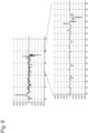
- Fig. 6 is a drawing illustrating a relationship between the flow rate of the fluid supplied to the retainer member pressurization chamber 10 and the slip out of the substrate WF.
- the vertical axis indicates the flow rate (mL) of the fluid supplied to the retainer member pressurization chamber 10 and the horizontal axis indicates the time (second).
- the upper drawing in Fig. 6 indicates the flow rate of the fluid supplied to the retainer member pressurization chamber 10 in the process in which the slip out occurs from the start of the polishing process of the substrate WF
- the lower drawing in Fig. 6 indicates the enlarged part where the slip out of the substrate WF occurs.
- the substrate WF contacts the retainer member 3 and presses up the retainer member 3 and presses back the retainer member 3 by the supply of the fluid from the fluid supply source 30, and this causes flow-in/flow-out of the fluid to the retainer member pressurization chamber 10.
- the flow rate of the fluid supplied to the retainer member pressurization chamber 10 significantly changes.
- the amount of change per unit time (for example, every 0.1 seconds) of the flow rate of the fluid supplied to the retainer member pressurization chamber 10 exceeds the preset threshold value at the timing, and thus the slip out detector 910 can detect the slip out of the substrate WF from the polishing head 302.
- accuracy of detection of slip out of the substrate WF from the polishing head 302 can be improved. That is, as in the related art, to detect the slip out of the substrate based on the change in pressure/flow rate of the fluid supplied to the back surface of the substrate, since the noise caused by the vibration during polishing is directly reflected to the pressure/flow rate of the fluid, erroneous detection due to the noise possibly occurs.
- the slip out of the substrate WF is detected based on the change in flow rate of the fluid supplied to the retainer member pressurization chamber 10, but this should not be construed in a limiting sense.
- the slip out of the substrate WF can be detected based on the change in pressure of the fluid supplied to the retainer member pressurization chamber 10.
- the slip out detector 910 is configured to detect the slip out of the substrate WF from the polishing head 302 when the amount of change per unit time of the pressure of the fluid detected by the pressure sensor P6 exceeds the preset threshold value.
- the retainer member pressurization chamber 10 is integrally formed in the rectangular frame shape has been described, but the embodiment is not limited to this.
- the retainer member pressurization chambers 10 may be separately disposed to the respective four sides of the retainer member 3 and the flow rate sensors F6 may be disposed to the respective retainer member pressurization chambers 10.
- the slip out detector 910 can detect the slip out of the substrate WF based on the change in flow rate of the fluid detected by any of the four flow rate sensors F6.
- the slip out detector 910 can combine another slip out detection.
- the polishing unit 300 includes the polishing table ammeter 359' as a table torque detector to detect a physical quantity correlated to a rotating torque of the polishing table 350.
- the slip out detector can detect the slip out of the substrate WF from the polishing head 302 based on the change in drive current detected by the polishing table ammeter 359'.
- the polishing unit 300 includes the polishing head ammeter 304' as a polishing head torque detector to detect a physical quantity correlated to the rotating torque of the polishing head 302.
- the slip out detector 910 can detect the slip out of the substrate WF from the polishing head 302 based on the change in drive current detected by the polishing head ammeter 304'.
- the polishing unit 300 includes a light emitting member 370 to emit light to the polishing pad 352 and a light receiving member 372 to receive light reflected by the polishing pad 352.
- the slip out detector 910 can detect the slip out of the substrate WF from the polishing head 302 based on a change in light amount of a reflected light emitted from the light emitting member 370 and received by the light receiving member 372. That is, since the polishing pad 352 and the substrate WF have different reflectivity of light, when the substrate WF goes out of the polishing head 302 and appears in an emission region of the light, the light amount of the reflected light changes.
- the slip out detector 910 can detect the slip out of the substrate WF from the polishing head 302 based on a change in color of the reflected light emitted from the light emitting member 370 and received by the light receiving member 372. That is, the slip out detector 910 emits the light to the polishing pad 352 before the polishing process of the substrate WF is performed, and registers a reference color of the polishing pad based on the light reflected by the polishing pad 352. During the polishing process of the substrate WF, the slip out detector 910 compares the color based on the light reflected by the polishing pad 352 with the reference color.
- the slip out detector 910 detects the color different from the reference color of the polishing pad 352, and therefore the slip out of the substrate WF from the polishing head 302 can be detected.
- the slip out detector 910 can determine that the substrate WF slips out and stop the polishing unit 300. Furthermore, monitoring means, such as a CCD camera, that captures an image of the surface of the polishing pad 352 is disposed near the outside of the polishing head 302 above the polishing pad 352, and this allows the slip out detector 910 to detect the slip out of the substrate WF from the polishing head 302.
- monitoring means such as a CCD camera
- the polishing unit 300 includes a setting change detector 930 that detects an issuance of a setting change command to change at least one setting value of a height of the polishing head 302 with respect to the polishing pad 352, pressures of a plurality of substrate pressurization chambers (the center chamber 5, the ripple chamber 6, the middle chamber 7, the outer chamber 8, and the edge chamber 9) formed in the polishing head 302, the pressure of the retainer member pressurization chamber 10, the rotational speed of the polishing table 350, the rotational speed of the polishing head 302, or the turning speed of the arm 360.
- the setting change detector 930 can be achieved as a function block of the control device 900.
- the setting change detector 930 can detect the setting change command input by an operator via a Graphical User Interface (GUI) screen disposed in the substrate processing apparatus 1000 or the setting change command by an automatic command issued from a host computer in the substrate processing apparatus 1000.
- GUI Graphical User Interface
- the slip out detector 910 is configured to stop the detection of the slip out of the substrate WF from the polishing head 302 for a predetermined period.
- the slip out detector 910 disables the slip out detection for the predetermined period to ensure suppressing the erroneous detection.
- the configuration is not limited to the above-described configuration, and the slip out detector 910 can be configured to detect the slip out in a case where the turning (swing) speed of the arm 360 is changed during the polishing of the substrate WF as well. That is, in a case where the speed of the arm 360 is always changed or the arm 360 is moved at a constant speed and goes back at the end portion when the substrate WF is polished while the arm 360 is swung, the slip out detector 910 allows enabling the slip out detection.
- Fig. 7 is a flowchart depicting the substrate processing method of this embodiment.
- the operator prepares various recipes for the substrate process via the GUI screen (Step 102) to start the polishing process of the substrate (Step 104).
- the polishing step holds the substrate WF by the polishing head 302 and presses the polishing pad 352, and performs a relative movement between the substrate WF and the polishing pad 352 to polish the substrate WF.
- the substrate processing method determines whether the slip out detection function of the substrate WF is enabled (Step 106), and terminates the process when the slip out detection function is not enabled (Step 106: No).
- the slip out detector 910 determines whether the polishing head 302 is within a monitoring target range (Step 108). That is, when the polishing process of the substrate WF starts, the polishing head 302 receives the substrate at the substrate transfer position and conveys the substrate on the polishing table 350 by turning of the arm 360. At this time, whether the slip out occurs is not determined until the polishing head 302 is carried in the predetermined range on the polishing table 350 so as not to cause the erroneous detection of the slip out based on the change in turning torque of the arm 360.
- the slip out detector 910 determines whether the monitoring condition for the slip out detection has been changed (Step 110).
- the slip out detector 910 can perform the determination of Step 110 depending on whether the setting change detector 930 detects the above-described setting change command.
- the slip out detector 910 stands by for a predetermined detection start delay period (Step 112). This allows suppressing the erroneous detection of the slip out caused by setting change.
- the slip out detector 910 performs the slip out detection of the substrate WF and determines whether the slip out occurs (Step 116).
- the slip out detector 910 can detect the slip out of the substrate WF based on the change in turning torque of the arm 360 or, in addition to that, based on the change in flow rate of the fluid supplied to the retainer member pressurization chamber 10.
- the slip out detector 910 may combine slip out detection based on a change in rotating torque of the polishing table 350/the polishing head 302, or slip out detection based on a change in color or light amount of the reflected light received by the light receiving member 372.
- Step 116: Yes When the slip out of the substrate WF is detected (Step 116: Yes), the slip out detector 910 performs an abnormal stop process of the polishing unit 300 (Step 118). On the other hand, when the slip out of the substrate WF is not detected, (Step 116: No), the slip out detector 910 determines whether the polishing process has been terminated (Step 120). When the polishing process is not terminated (Step 120: No), the slip out detector 910 returns the process to Step 108 to repeat the process. On the other hand, when the polishing process has been terminated (Step 120: Yes), the slip out detector 910 terminates the process.
- the control device 900 includes a storage medium 940.
- the storage medium 940 stores programs to cause the computer (control device 900) in the substrate processing apparatus 1000 to execute the respective steps in the above-described substrate processing method.
- a CPU (central processing device) in the control device 900 can read and execute the program stored in the storage medium 940.
- the program can be recorded in a computer-readable storage medium and provided to the control device 900 via the storage medium. Alternatively, the program may be provided to the control device 900 via a communication network, such as the Internet.
Landscapes
- Engineering & Computer Science (AREA)
- Mechanical Engineering (AREA)
- Finish Polishing, Edge Sharpening, And Grinding By Specific Grinding Devices (AREA)
- Mechanical Treatment Of Semiconductor (AREA)
- Constituent Portions Of Griding Lathes, Driving, Sensing And Control (AREA)
Applications Claiming Priority (1)
| Application Number | Priority Date | Filing Date | Title |
|---|---|---|---|
| JP2020111535A JP7443169B2 (ja) | 2020-06-29 | 2020-06-29 | 基板処理装置、基板処理方法、および基板処理方法を基板処理装置のコンピュータに実行させるためのプログラムを格納した記憶媒体 |
Publications (2)
| Publication Number | Publication Date |
|---|---|
| EP3932615A1 EP3932615A1 (en) | 2022-01-05 |
| EP3932615B1 true EP3932615B1 (en) | 2023-08-16 |
Family
ID=76641617
Family Applications (1)
| Application Number | Title | Priority Date | Filing Date |
|---|---|---|---|
| EP21181846.3A Active EP3932615B1 (en) | 2020-06-29 | 2021-06-25 | Substrate processing apparatus and substrate processing method, |
Country Status (6)
| Country | Link |
|---|---|
| US (1) | US11911868B2 (https=) |
| EP (1) | EP3932615B1 (https=) |
| JP (1) | JP7443169B2 (https=) |
| KR (1) | KR102884989B1 (https=) |
| CN (1) | CN114102426B (https=) |
| TW (1) | TWI897976B (https=) |
Families Citing this family (1)
| Publication number | Priority date | Publication date | Assignee | Title |
|---|---|---|---|---|
| JP2025136592A (ja) * | 2024-03-07 | 2025-09-19 | 株式会社荏原製作所 | 基板研磨装置、基板処理装置、基板研磨方法、およびプログラム |
Family Cites Families (28)
| Publication number | Priority date | Publication date | Assignee | Title |
|---|---|---|---|---|
| JPH10214806A (ja) * | 1997-01-31 | 1998-08-11 | Hitachi Chem Co Ltd | 半導体基板の研磨方法 |
| JP3705670B2 (ja) | 1997-02-19 | 2005-10-12 | 株式会社荏原製作所 | ポリッシング装置及び方法 |
| JP2977543B2 (ja) * | 1997-09-02 | 1999-11-15 | 松下電子工業株式会社 | 化学的機械研磨装置及び化学的機械研磨方法 |
| JP3572917B2 (ja) * | 1997-12-09 | 2004-10-06 | 信越半導体株式会社 | 半導体ウエーハの両面研磨方法及びその装置 |
| JP2001000964A (ja) * | 1999-06-22 | 2001-01-09 | Japan Atom Energy Res Inst | 超音波により水相から有機溶媒を除去する方法 |
| JP2001096455A (ja) | 1999-09-28 | 2001-04-10 | Ebara Corp | 研磨装置 |
| JP3922887B2 (ja) | 2001-03-16 | 2007-05-30 | 株式会社荏原製作所 | ドレッサ及びポリッシング装置 |
| US6796879B2 (en) * | 2002-01-12 | 2004-09-28 | Taiwan Semiconductor Manufacturing Co., Ltd. | Dual wafer-loss sensor and water-resistant sensor holder |
| JP4102081B2 (ja) * | 2002-02-28 | 2008-06-18 | 株式会社荏原製作所 | 研磨装置及び研磨面の異物検出方法 |
| JP2004106123A (ja) * | 2002-09-19 | 2004-04-08 | Toshiba Corp | 研磨方法、cmp装置及び膜厚測定装置 |
| US6946397B2 (en) * | 2003-11-17 | 2005-09-20 | Taiwan Semiconductor Manufacturing Company, Ltd. | Chemical mechanical polishing process with reduced defects in a copper process |
| JP2005251924A (ja) * | 2004-03-03 | 2005-09-15 | Nikon Corp | ウエハの保持部材からの飛び出し検出方法、ウエハ部分割れ検出方法、及びcmp装置におけるウエハの飛び出し検出方法、cmp装置におけるウエハの部分割れ検出方法、及びウエハの保持部材からの一部飛び出し検出方法 |
| JP2007134478A (ja) * | 2005-11-10 | 2007-05-31 | Tokyo Seimitsu Co Ltd | ウェーハ研磨装置及び方法 |
| JP4814677B2 (ja) * | 2006-03-31 | 2011-11-16 | 株式会社荏原製作所 | 基板保持装置および研磨装置 |
| JP5004494B2 (ja) * | 2006-04-14 | 2012-08-22 | 富士フイルム株式会社 | 化学的機械的研磨方法 |
| TWI572441B (zh) * | 2008-08-05 | 2017-03-01 | 荏原製作所股份有限公司 | 硏磨方法及裝置 |
| EP2457689B1 (en) * | 2009-07-22 | 2013-06-26 | JTEKT Corporation | Method and device for preventing slip of work piece |
| US8034723B2 (en) * | 2009-12-25 | 2011-10-11 | Tokyo Electron Limited | Film deposition apparatus and film deposition method |
| US9240042B2 (en) | 2013-10-24 | 2016-01-19 | Globalfoundries Inc. | Wafer slip detection during CMP processing |
| US9184084B2 (en) * | 2014-01-28 | 2015-11-10 | Lam Research Corporation | Wafer handling traction control system |
| JP6266493B2 (ja) * | 2014-03-20 | 2018-01-24 | 株式会社荏原製作所 | 研磨装置及び研磨方法 |
| JP6546845B2 (ja) * | 2015-12-18 | 2019-07-17 | 株式会社荏原製作所 | 研磨装置、制御方法及びプログラム |
| JP6357260B2 (ja) * | 2016-09-30 | 2018-07-11 | 株式会社荏原製作所 | 研磨装置、及び研磨方法 |
| JP6882017B2 (ja) * | 2017-03-06 | 2021-06-02 | 株式会社荏原製作所 | 研磨方法、研磨装置、および基板処理システム |
| JP6913318B2 (ja) * | 2017-06-16 | 2021-08-04 | 山九株式会社 | 重量物横移動用のリフト |
| JP6887371B2 (ja) * | 2017-12-20 | 2021-06-16 | 株式会社荏原製作所 | 基板処理装置、基板処理装置の制御方法、プログラムを格納した記憶媒体 |
| JP6487613B1 (ja) | 2019-01-11 | 2019-03-20 | キコヘッド株式会社 | Il−33発現抑制剤の製造方法 |
| JP7374710B2 (ja) | 2019-10-25 | 2023-11-07 | 株式会社荏原製作所 | 研磨方法および研磨装置 |
-
2020
- 2020-06-29 JP JP2020111535A patent/JP7443169B2/ja active Active
-
2021
- 2021-06-08 TW TW110120759A patent/TWI897976B/zh active
- 2021-06-23 KR KR1020210081369A patent/KR102884989B1/ko active Active
- 2021-06-23 US US17/355,525 patent/US11911868B2/en active Active
- 2021-06-25 EP EP21181846.3A patent/EP3932615B1/en active Active
- 2021-06-28 CN CN202110717360.3A patent/CN114102426B/zh active Active
Also Published As
| Publication number | Publication date |
|---|---|
| EP3932615A1 (en) | 2022-01-05 |
| JP7443169B2 (ja) | 2024-03-05 |
| US20210402548A1 (en) | 2021-12-30 |
| TWI897976B (zh) | 2025-09-21 |
| US11911868B2 (en) | 2024-02-27 |
| KR102884989B1 (ko) | 2025-11-12 |
| JP2022010795A (ja) | 2022-01-17 |
| CN114102426A (zh) | 2022-03-01 |
| KR20220001477A (ko) | 2022-01-05 |
| CN114102426B (zh) | 2026-03-06 |
| TW202218805A (zh) | 2022-05-16 |
Similar Documents
| Publication | Publication Date | Title |
|---|---|---|
| US11224956B2 (en) | Polishing apparatus | |
| KR101810331B1 (ko) | 연마 장치 | |
| US9999956B2 (en) | Polishing device and polishing method | |
| KR101972647B1 (ko) | 연마 장치 및 연마 방법 | |
| JP5856546B2 (ja) | 研磨装置および研磨方法 | |
| EP3932615B1 (en) | Substrate processing apparatus and substrate processing method, | |
| US20240139905A1 (en) | Carrier head acoustic monitoring with sensor in platen | |
| CN119526260A (zh) | 信息处理装置、基板处理装置及信息处理方法 | |
| TW202535602A (zh) | 基板研磨裝置、基板處理裝置、基板研磨方法、及程式 | |
| JP2008124402A (ja) | 半導体製造装置の自己診断方法および半導体製造装置、並びに研磨装置の自己診断方法および研磨装置 |
Legal Events
| Date | Code | Title | Description |
|---|---|---|---|
| PUAI | Public reference made under article 153(3) epc to a published international application that has entered the european phase |
Free format text: ORIGINAL CODE: 0009012 |
|
| STAA | Information on the status of an ep patent application or granted ep patent |
Free format text: STATUS: THE APPLICATION HAS BEEN PUBLISHED |
|
| AK | Designated contracting states |
Kind code of ref document: A1 Designated state(s): AL AT BE BG CH CY CZ DE DK EE ES FI FR GB GR HR HU IE IS IT LI LT LU LV MC MK MT NL NO PL PT RO RS SE SI SK SM TR |
|
| B565 | Issuance of search results under rule 164(2) epc |
Effective date: 20211125 |
|
| STAA | Information on the status of an ep patent application or granted ep patent |
Free format text: STATUS: REQUEST FOR EXAMINATION WAS MADE |
|
| 17P | Request for examination filed |
Effective date: 20220328 |
|
| RBV | Designated contracting states (corrected) |
Designated state(s): AL AT BE BG CH CY CZ DE DK EE ES FI FR GB GR HR HU IE IS IT LI LT LU LV MC MK MT NL NO PL PT RO RS SE SI SK SM TR |
|
| GRAP | Despatch of communication of intention to grant a patent |
Free format text: ORIGINAL CODE: EPIDOSNIGR1 |
|
| STAA | Information on the status of an ep patent application or granted ep patent |
Free format text: STATUS: GRANT OF PATENT IS INTENDED |
|
| INTG | Intention to grant announced |
Effective date: 20230307 |
|
| GRAS | Grant fee paid |
Free format text: ORIGINAL CODE: EPIDOSNIGR3 |
|
| GRAA | (expected) grant |
Free format text: ORIGINAL CODE: 0009210 |
|
| STAA | Information on the status of an ep patent application or granted ep patent |
Free format text: STATUS: THE PATENT HAS BEEN GRANTED |
|
| RAP3 | Party data changed (applicant data changed or rights of an application transferred) |
Owner name: EBARA CORPORATION |
|
| AK | Designated contracting states |
Kind code of ref document: B1 Designated state(s): AL AT BE BG CH CY CZ DE DK EE ES FI FR GB GR HR HU IE IS IT LI LT LU LV MC MK MT NL NO PL PT RO RS SE SI SK SM TR |
|
| P01 | Opt-out of the competence of the unified patent court (upc) registered |
Effective date: 20230707 |
|
| REG | Reference to a national code |
Ref country code: CH Ref legal event code: EP Ref country code: DE Ref legal event code: R096 Ref document number: 602021004278 Country of ref document: DE |
|
| REG | Reference to a national code |
Ref country code: IE Ref legal event code: FG4D |
|
| REG | Reference to a national code |
Ref country code: LT Ref legal event code: MG9D |
|
| REG | Reference to a national code |
Ref country code: NL Ref legal event code: MP Effective date: 20230816 |
|
| PG25 | Lapsed in a contracting state [announced via postgrant information from national office to epo] |
Ref country code: GR Free format text: LAPSE BECAUSE OF FAILURE TO SUBMIT A TRANSLATION OF THE DESCRIPTION OR TO PAY THE FEE WITHIN THE PRESCRIBED TIME-LIMIT Effective date: 20231117 |
|
| PG25 | Lapsed in a contracting state [announced via postgrant information from national office to epo] |
Ref country code: IS Free format text: LAPSE BECAUSE OF FAILURE TO SUBMIT A TRANSLATION OF THE DESCRIPTION OR TO PAY THE FEE WITHIN THE PRESCRIBED TIME-LIMIT Effective date: 20231216 |
|
| PG25 | Lapsed in a contracting state [announced via postgrant information from national office to epo] |
Ref country code: SE Free format text: LAPSE BECAUSE OF FAILURE TO SUBMIT A TRANSLATION OF THE DESCRIPTION OR TO PAY THE FEE WITHIN THE PRESCRIBED TIME-LIMIT Effective date: 20230816 Ref country code: RS Free format text: LAPSE BECAUSE OF FAILURE TO SUBMIT A TRANSLATION OF THE DESCRIPTION OR TO PAY THE FEE WITHIN THE PRESCRIBED TIME-LIMIT Effective date: 20230816 Ref country code: PT Free format text: LAPSE BECAUSE OF FAILURE TO SUBMIT A TRANSLATION OF THE DESCRIPTION OR TO PAY THE FEE WITHIN THE PRESCRIBED TIME-LIMIT Effective date: 20231218 Ref country code: NO Free format text: LAPSE BECAUSE OF FAILURE TO SUBMIT A TRANSLATION OF THE DESCRIPTION OR TO PAY THE FEE WITHIN THE PRESCRIBED TIME-LIMIT Effective date: 20231116 Ref country code: NL Free format text: LAPSE BECAUSE OF FAILURE TO SUBMIT A TRANSLATION OF THE DESCRIPTION OR TO PAY THE FEE WITHIN THE PRESCRIBED TIME-LIMIT Effective date: 20230816 Ref country code: LV Free format text: LAPSE BECAUSE OF FAILURE TO SUBMIT A TRANSLATION OF THE DESCRIPTION OR TO PAY THE FEE WITHIN THE PRESCRIBED TIME-LIMIT Effective date: 20230816 Ref country code: LT Free format text: LAPSE BECAUSE OF FAILURE TO SUBMIT A TRANSLATION OF THE DESCRIPTION OR TO PAY THE FEE WITHIN THE PRESCRIBED TIME-LIMIT Effective date: 20230816 Ref country code: IS Free format text: LAPSE BECAUSE OF FAILURE TO SUBMIT A TRANSLATION OF THE DESCRIPTION OR TO PAY THE FEE WITHIN THE PRESCRIBED TIME-LIMIT Effective date: 20231216 Ref country code: HR Free format text: LAPSE BECAUSE OF FAILURE TO SUBMIT A TRANSLATION OF THE DESCRIPTION OR TO PAY THE FEE WITHIN THE PRESCRIBED TIME-LIMIT Effective date: 20230816 Ref country code: GR Free format text: LAPSE BECAUSE OF FAILURE TO SUBMIT A TRANSLATION OF THE DESCRIPTION OR TO PAY THE FEE WITHIN THE PRESCRIBED TIME-LIMIT Effective date: 20231117 Ref country code: FI Free format text: LAPSE BECAUSE OF FAILURE TO SUBMIT A TRANSLATION OF THE DESCRIPTION OR TO PAY THE FEE WITHIN THE PRESCRIBED TIME-LIMIT Effective date: 20230816 |
|
| PG25 | Lapsed in a contracting state [announced via postgrant information from national office to epo] |
Ref country code: PL Free format text: LAPSE BECAUSE OF FAILURE TO SUBMIT A TRANSLATION OF THE DESCRIPTION OR TO PAY THE FEE WITHIN THE PRESCRIBED TIME-LIMIT Effective date: 20230816 |
|
| REG | Reference to a national code |
Ref country code: AT Ref legal event code: UEP Ref document number: 1599574 Country of ref document: AT Kind code of ref document: T Effective date: 20230816 |
|
| PG25 | Lapsed in a contracting state [announced via postgrant information from national office to epo] |
Ref country code: ES Free format text: LAPSE BECAUSE OF FAILURE TO SUBMIT A TRANSLATION OF THE DESCRIPTION OR TO PAY THE FEE WITHIN THE PRESCRIBED TIME-LIMIT Effective date: 20230816 |
|
| PG25 | Lapsed in a contracting state [announced via postgrant information from national office to epo] |
Ref country code: SM Free format text: LAPSE BECAUSE OF FAILURE TO SUBMIT A TRANSLATION OF THE DESCRIPTION OR TO PAY THE FEE WITHIN THE PRESCRIBED TIME-LIMIT Effective date: 20230816 Ref country code: RO Free format text: LAPSE BECAUSE OF FAILURE TO SUBMIT A TRANSLATION OF THE DESCRIPTION OR TO PAY THE FEE WITHIN THE PRESCRIBED TIME-LIMIT Effective date: 20230816 Ref country code: ES Free format text: LAPSE BECAUSE OF FAILURE TO SUBMIT A TRANSLATION OF THE DESCRIPTION OR TO PAY THE FEE WITHIN THE PRESCRIBED TIME-LIMIT Effective date: 20230816 Ref country code: EE Free format text: LAPSE BECAUSE OF FAILURE TO SUBMIT A TRANSLATION OF THE DESCRIPTION OR TO PAY THE FEE WITHIN THE PRESCRIBED TIME-LIMIT Effective date: 20230816 Ref country code: DK Free format text: LAPSE BECAUSE OF FAILURE TO SUBMIT A TRANSLATION OF THE DESCRIPTION OR TO PAY THE FEE WITHIN THE PRESCRIBED TIME-LIMIT Effective date: 20230816 Ref country code: CZ Free format text: LAPSE BECAUSE OF FAILURE TO SUBMIT A TRANSLATION OF THE DESCRIPTION OR TO PAY THE FEE WITHIN THE PRESCRIBED TIME-LIMIT Effective date: 20230816 Ref country code: SK Free format text: LAPSE BECAUSE OF FAILURE TO SUBMIT A TRANSLATION OF THE DESCRIPTION OR TO PAY THE FEE WITHIN THE PRESCRIBED TIME-LIMIT Effective date: 20230816 |
|
| REG | Reference to a national code |
Ref country code: DE Ref legal event code: R097 Ref document number: 602021004278 Country of ref document: DE |
|
| PLBE | No opposition filed within time limit |
Free format text: ORIGINAL CODE: 0009261 |
|
| STAA | Information on the status of an ep patent application or granted ep patent |
Free format text: STATUS: NO OPPOSITION FILED WITHIN TIME LIMIT |
|
| 26N | No opposition filed |
Effective date: 20240517 |
|
| PG25 | Lapsed in a contracting state [announced via postgrant information from national office to epo] |
Ref country code: IT Free format text: LAPSE BECAUSE OF FAILURE TO SUBMIT A TRANSLATION OF THE DESCRIPTION OR TO PAY THE FEE WITHIN THE PRESCRIBED TIME-LIMIT Effective date: 20230816 Ref country code: SI Free format text: LAPSE BECAUSE OF FAILURE TO SUBMIT A TRANSLATION OF THE DESCRIPTION OR TO PAY THE FEE WITHIN THE PRESCRIBED TIME-LIMIT Effective date: 20230816 |
|
| PG25 | Lapsed in a contracting state [announced via postgrant information from national office to epo] |
Ref country code: BG Free format text: LAPSE BECAUSE OF FAILURE TO SUBMIT A TRANSLATION OF THE DESCRIPTION OR TO PAY THE FEE WITHIN THE PRESCRIBED TIME-LIMIT Effective date: 20230816 |
|
| PG25 | Lapsed in a contracting state [announced via postgrant information from national office to epo] |
Ref country code: BG Free format text: LAPSE BECAUSE OF FAILURE TO SUBMIT A TRANSLATION OF THE DESCRIPTION OR TO PAY THE FEE WITHIN THE PRESCRIBED TIME-LIMIT Effective date: 20230816 |
|
| REG | Reference to a national code |
Ref country code: DE Ref legal event code: R119 Ref document number: 602021004278 Country of ref document: DE |
|
| PG25 | Lapsed in a contracting state [announced via postgrant information from national office to epo] |
Ref country code: MC Free format text: LAPSE BECAUSE OF FAILURE TO SUBMIT A TRANSLATION OF THE DESCRIPTION OR TO PAY THE FEE WITHIN THE PRESCRIBED TIME-LIMIT Effective date: 20230816 |
|
| REG | Reference to a national code |
Ref country code: CH Ref legal event code: PL |
|
| PG25 | Lapsed in a contracting state [announced via postgrant information from national office to epo] |
Ref country code: LU Free format text: LAPSE BECAUSE OF NON-PAYMENT OF DUE FEES Effective date: 20240625 |
|
| PG25 | Lapsed in a contracting state [announced via postgrant information from national office to epo] |
Ref country code: DE Free format text: LAPSE BECAUSE OF NON-PAYMENT OF DUE FEES Effective date: 20250101 |
|
| PG25 | Lapsed in a contracting state [announced via postgrant information from national office to epo] |
Ref country code: IE Free format text: LAPSE BECAUSE OF NON-PAYMENT OF DUE FEES Effective date: 20240625 |
|
| PG25 | Lapsed in a contracting state [announced via postgrant information from national office to epo] |
Ref country code: BE Free format text: LAPSE BECAUSE OF NON-PAYMENT OF DUE FEES Effective date: 20240630 Ref country code: CH Free format text: LAPSE BECAUSE OF NON-PAYMENT OF DUE FEES Effective date: 20240630 |
|
| PG25 | Lapsed in a contracting state [announced via postgrant information from national office to epo] |
Ref country code: FR Free format text: LAPSE BECAUSE OF NON-PAYMENT OF DUE FEES Effective date: 20240630 |
|
| REG | Reference to a national code |
Ref country code: BE Ref legal event code: MM Effective date: 20240630 |
|
| PGFP | Annual fee paid to national office [announced via postgrant information from national office to epo] |
Ref country code: AT Payment date: 20250721 Year of fee payment: 5 |
|
| PG25 | Lapsed in a contracting state [announced via postgrant information from national office to epo] |
Ref country code: CY Free format text: LAPSE BECAUSE OF FAILURE TO SUBMIT A TRANSLATION OF THE DESCRIPTION OR TO PAY THE FEE WITHIN THE PRESCRIBED TIME-LIMIT; INVALID AB INITIO Effective date: 20210625 |
|
| GBPC | Gb: european patent ceased through non-payment of renewal fee |
Effective date: 20250625 |
|
| PG25 | Lapsed in a contracting state [announced via postgrant information from national office to epo] |
Ref country code: HU Free format text: LAPSE BECAUSE OF FAILURE TO SUBMIT A TRANSLATION OF THE DESCRIPTION OR TO PAY THE FEE WITHIN THE PRESCRIBED TIME-LIMIT; INVALID AB INITIO Effective date: 20210625 |
|
| PG25 | Lapsed in a contracting state [announced via postgrant information from national office to epo] |
Ref country code: GB Free format text: LAPSE BECAUSE OF NON-PAYMENT OF DUE FEES Effective date: 20250625 |