EP3932571A1 - Air purge unit - Google Patents
Air purge unit Download PDFInfo
- Publication number
- EP3932571A1 EP3932571A1 EP20763761.2A EP20763761A EP3932571A1 EP 3932571 A1 EP3932571 A1 EP 3932571A1 EP 20763761 A EP20763761 A EP 20763761A EP 3932571 A1 EP3932571 A1 EP 3932571A1
- Authority
- EP
- European Patent Office
- Prior art keywords
- air
- purge unit
- photoelectric sensor
- housing
- blow
- Prior art date
- Legal status (The legal status is an assumption and is not a legal conclusion. Google has not performed a legal analysis and makes no representation as to the accuracy of the status listed.)
- Granted
Links
Images




Classifications
-
- G—PHYSICS
- G01—MEASURING; TESTING
- G01V—GEOPHYSICS; GRAVITATIONAL MEASUREMENTS; DETECTING MASSES OR OBJECTS; TAGS
- G01V8/00—Prospecting or detecting by optical means
- G01V8/10—Detecting, e.g. by using light barriers
-
- G—PHYSICS
- G02—OPTICS
- G02B—OPTICAL ELEMENTS, SYSTEMS OR APPARATUS
- G02B27/00—Optical systems or apparatus not provided for by any of the groups G02B1/00 - G02B26/00, G02B30/00
- G02B27/0006—Optical systems or apparatus not provided for by any of the groups G02B1/00 - G02B26/00, G02B30/00 with means to keep optical surfaces clean, e.g. by preventing or removing dirt, stains, contamination, condensation
-
- B—PERFORMING OPERATIONS; TRANSPORTING
- B05—SPRAYING OR ATOMISING IN GENERAL; APPLYING FLUENT MATERIALS TO SURFACES, IN GENERAL
- B05B—SPRAYING APPARATUS; ATOMISING APPARATUS; NOZZLES
- B05B1/00—Nozzles, spray heads or other outlets, with or without auxiliary devices such as valves, heating means
- B05B1/02—Nozzles, spray heads or other outlets, with or without auxiliary devices such as valves, heating means designed to produce a jet, spray, or other discharge of particular shape or nature, e.g. in single drops, or having an outlet of particular shape
- B05B1/06—Nozzles, spray heads or other outlets, with or without auxiliary devices such as valves, heating means designed to produce a jet, spray, or other discharge of particular shape or nature, e.g. in single drops, or having an outlet of particular shape in annular, tubular or hollow conical form
-
- B—PERFORMING OPERATIONS; TRANSPORTING
- B08—CLEANING
- B08B—CLEANING IN GENERAL; PREVENTION OF FOULING IN GENERAL
- B08B5/00—Cleaning by methods involving the use of air flow or gas flow
- B08B5/02—Cleaning by the force of jets, e.g. blowing-out cavities
-
- G—PHYSICS
- G01—MEASURING; TESTING
- G01S—RADIO DIRECTION-FINDING; RADIO NAVIGATION; DETERMINING DISTANCE OR VELOCITY BY USE OF RADIO WAVES; LOCATING OR PRESENCE-DETECTING BY USE OF THE REFLECTION OR RERADIATION OF RADIO WAVES; ANALOGOUS ARRANGEMENTS USING OTHER WAVES
- G01S7/00—Details of systems according to groups G01S13/00, G01S15/00, G01S17/00
- G01S7/48—Details of systems according to groups G01S13/00, G01S15/00, G01S17/00 of systems according to group G01S17/00
- G01S7/481—Constructional features, e.g. arrangements of optical elements
-
- G—PHYSICS
- G01—MEASURING; TESTING
- G01V—GEOPHYSICS; GRAVITATIONAL MEASUREMENTS; DETECTING MASSES OR OBJECTS; TAGS
- G01V8/00—Prospecting or detecting by optical means
- G01V8/10—Detecting, e.g. by using light barriers
- G01V8/12—Detecting, e.g. by using light barriers using one transmitter and one receiver
- G01V8/14—Detecting, e.g. by using light barriers using one transmitter and one receiver using reflectors
-
- B—PERFORMING OPERATIONS; TRANSPORTING
- B05—SPRAYING OR ATOMISING IN GENERAL; APPLYING FLUENT MATERIALS TO SURFACES, IN GENERAL
- B05B—SPRAYING APPARATUS; ATOMISING APPARATUS; NOZZLES
- B05B1/00—Nozzles, spray heads or other outlets, with or without auxiliary devices such as valves, heating means
- B05B1/005—Nozzles or other outlets specially adapted for discharging one or more gases
-
- B—PERFORMING OPERATIONS; TRANSPORTING
- B05—SPRAYING OR ATOMISING IN GENERAL; APPLYING FLUENT MATERIALS TO SURFACES, IN GENERAL
- B05B—SPRAYING APPARATUS; ATOMISING APPARATUS; NOZZLES
- B05B1/00—Nozzles, spray heads or other outlets, with or without auxiliary devices such as valves, heating means
- B05B1/02—Nozzles, spray heads or other outlets, with or without auxiliary devices such as valves, heating means designed to produce a jet, spray, or other discharge of particular shape or nature, e.g. in single drops, or having an outlet of particular shape
- B05B1/04—Nozzles, spray heads or other outlets, with or without auxiliary devices such as valves, heating means designed to produce a jet, spray, or other discharge of particular shape or nature, e.g. in single drops, or having an outlet of particular shape in flat form, e.g. fan-like, sheet-like
- B05B1/044—Slits, e.g. narrow openings defined by two straight and parallel lips; Elongated outlets for producing very wide discharges, e.g. fluid curtains
-
- B—PERFORMING OPERATIONS; TRANSPORTING
- B05—SPRAYING OR ATOMISING IN GENERAL; APPLYING FLUENT MATERIALS TO SURFACES, IN GENERAL
- B05B—SPRAYING APPARATUS; ATOMISING APPARATUS; NOZZLES
- B05B1/00—Nozzles, spray heads or other outlets, with or without auxiliary devices such as valves, heating means
- B05B1/14—Nozzles, spray heads or other outlets, with or without auxiliary devices such as valves, heating means with multiple outlet openings; with strainers in or outside the outlet opening
-
- G—PHYSICS
- G01—MEASURING; TESTING
- G01S—RADIO DIRECTION-FINDING; RADIO NAVIGATION; DETERMINING DISTANCE OR VELOCITY BY USE OF RADIO WAVES; LOCATING OR PRESENCE-DETECTING BY USE OF THE REFLECTION OR RERADIATION OF RADIO WAVES; ANALOGOUS ARRANGEMENTS USING OTHER WAVES
- G01S7/00—Details of systems according to groups G01S13/00, G01S15/00, G01S17/00
- G01S7/48—Details of systems according to groups G01S13/00, G01S15/00, G01S17/00 of systems according to group G01S17/00
- G01S7/497—Means for monitoring or calibrating
- G01S2007/4975—Means for monitoring or calibrating of sensor obstruction by, e.g. dirt- or ice-coating, e.g. by reflection measurement on front-screen
- G01S2007/4977—Means for monitoring or calibrating of sensor obstruction by, e.g. dirt- or ice-coating, e.g. by reflection measurement on front-screen including means to prevent or remove the obstruction
-
- G—PHYSICS
- G01—MEASURING; TESTING
- G01V—GEOPHYSICS; GRAVITATIONAL MEASUREMENTS; DETECTING MASSES OR OBJECTS; TAGS
- G01V8/00—Prospecting or detecting by optical means
- G01V8/10—Detecting, e.g. by using light barriers
- G01V8/12—Detecting, e.g. by using light barriers using one transmitter and one receiver
Definitions
- the invention relates to an air purge unit.
- the photoelectric sensor that detects whether a workpiece is present by using light.
- the photoelectric sensor performs various detections by, for example, emitting detection light toward the workpiece and then analyzing the light transmitted through the workpiece or reflected from the workpiece (for example, Patent Document 1).
- the photoelectric sensor may be installed in an environment where machining is performed. In such an environment, contamination such as dust and processing oil may adhere to a lens surface of the photoelectric sensor through which light passes, and the amount of light passing through the lens surface may decrease. Then, detection of the workpiece may not be performed properly. Therefore, a method is adopted, which attaches an air purge unit that blows air to the lens surface to the photoelectric sensor to prevent contamination from adhering to the lens surface.
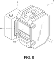
- an air purge unit 2 provided with an elongated air blow-out port 60 along a lens surface 11a may be attached to a photoelectric sensor 1 to remove contamination on the lens surface 11a.
- Patent Document 1 Japanese Laid-Open No. 2011-077050
- the invention provides an air purge unit that can remove contamination on the lens surface of the photoelectric sensor with a small air supply amount.
- An air purge unit includes: a housing; an air supply port for supplying air into the housing; and a plurality of air blow-out ports arranged on a side wall of the housing for blowing the air to a lens surface of a photoelectric sensor.
- the plurality of air blow-out ports are provided and arranged on the side wall of the air purge unit. Therefore, it is possible to blow air over a wide range of the lens surface with the plurality of air blow-out ports while reducing the size of each air blow-out port.
- the flow velocity of the air blown from each air blow-out port of the air purge unit increases as compared with the conventional air purge unit provided with one large air blow-out port. That is, the air purge unit according to the invention can remove contamination on the lens surface of the photoelectric sensor with a small air supply amount.
- the plurality of air blow-out ports may be provided side by side in a straight line.
- the plurality of air blow-out ports may be provided along an extending direction of the lens surface.
- the air blown out from the air blow-out ports of the air purge unit easily hits the lens surface, and the contamination adhering to the lens surface is efficiently removed.
- the plurality of air blow-out ports may be circular holes.
- corners connecting inner surfaces of the plurality of air blow-out ports and a side wall surface of the housing may be chamfered.
- air is blown out to spread from the air blow-out port. That is, since the air blown out from the air blow-out port hits a wide range of the lens surface, it is possible to remove contamination adhering over a wide range of the lens surface.
- an air purge unit that can remove contamination on a lens surface of a photoelectric sensor with a small air supply amount.
- FIG. 1 is a perspective view showing the appearance of a photoelectric sensor 1 according to the present embodiment.
- the photoelectric sensor 1 detects whether an object is present in a detection region and a surface state of the object by using light.
- the photoelectric sensor 1 used in the detection method is called a transmissive type.
- a method which performs detection by using a photoelectric sensor in which the light projector and the light receiver are integrated.
- light is emitted from the photoelectric sensor 1 toward a reflective plate or an object, and the reflected light is received by the same photoelectric sensor 1.
- the photoelectric sensor 1 detects whether an object is present and a surface state of the object by analyzing the received light.
- a photoelectric sensor that functions as both the light projector and the light receiver is called a reflective type.
- the reflective photoelectric sensor 1 will be described as an example, but the photoelectric sensor 1 to which the invention is applied may be a transmissive photoelectric sensor.
- FIG. 1 shows the photoelectric sensor 1 in a state where the air purge unit is not attached.
- the photoelectric sensor 1 includes a housing 10, a window 20, and a cable 21.
- the housing 10 houses various parts such as a light projecting element and a light receiving element included in the photoelectric sensor 1, and protects them from impact and contamination.
- the housing 10 may be made of, for example, metal or resin.
- the housing 10 has a front surface 11, a back surface 12, a side surface 13, a side surface 14, a top surface 15, and a bottom surface 16.
- the front surface 11 is a surface located on the traveling direction side of the projected light, and forms a frame surrounding the lens surface 11a through which light is transmitted.
- the back surface 12 is located at a position opposite to the front surface 11 with the inside of the housing 10 interposed therebetween.
- the housing 10 has the side surfaces 13 and 14 on the left and right.
- the side surface 13 and the side surface 14 are located opposite to each other with the inside of the housing 10 interposed therebetween.
- the housing 10 has the top surface 15 and the bottom surface 16 at the top and bottom. Similar to the side surfaces 13 and 14, the top surface 15 and the bottom surface 16 are located opposite to each other with the inside of the housing 10 interposed therebetween.
- the front surface 11 is a surface surrounding the lens surface 11a which transmits light.
- the lens surface 11a is formed of a member that transmits light, and transmits the light emitted from a light projecting unit (not shown) included in the photoelectric sensor 1. Further, the lens surface 11a transmits light that is reflected from a detection target and incident on a light receiving unit (not shown) included in the photoelectric sensor 1.
- the lens surface 11a may be made of, for example, transparent resin or glass.
- the light projecting unit is a unit that emits light to the detection region, and is composed of a light projecting element and a light projecting lens.
- the light projecting element is an element that emits light, and may be, for example, a laser or a light emitting diode.
- the light projecting lens converts the light generated from the light projecting element into parallel light. A part of the projecting lens may be exposed to the outside of the housing 10, and for example, the lens surface 11a shown in FIG. 1 may be the surface of the light projecting lens.
- the light receiving unit is a unit that detects incident light, and includes a light receiving element and a light receiving lens.
- the light receiving element is an element that detects light, and may be, for example, a photodiode or the like.
- the light receiving lens is a lens that forms an image of the light incident from the detection region on the light receiving element. A part of the light receiving lens may be exposed to the outside of the housing 10, and for example, the lens surface 11a shown in FIG. 1 may be the surface of the light receiving lens.
- the housing 10 has a communication hole 26.
- the communication hole 26 is a hole provided across the inside of the housing 10 so as to communicate the side surface 13 and the side surface 14.
- the housing 10 has two communication holes 26, which are respectively provided in the upper part and the lower part of the housing 10.
- the communication holes 26 are used when connecting the air purge unit described later to the photoelectric sensor 1. Specifically, the air purge unit is screwed to the photoelectric sensor 1 by inserting a screw from one end of the communication hole 26 and screwing the tip of the screw protruding from the other end into a screw hole provided in the air purge unit.
- the window 20 is located to cover an indicator lamp (not shown) provided on the upper part of the photoelectric sensor 1, and protects the indicator lamp from impact and contamination.
- the window 20 is preferably made of transparent resin or glass so that the user can visually recognize the indicator lamp from the outside.
- the indicator lamp outputs the operating status of the photoelectric sensor 1 by emitting light.
- the operating status may include, for example, the power supply status and the detection status of the photoelectric sensor 1.
- the indicator lamp may be composed of a light emitting element such as a light emitting diode.
- the indicator lamp may be turned on, for example, when the power of the photoelectric sensor 1 is turned on or when the photoelectric sensor 1 detects a workpiece.
- the cable 21 transmits the electric power supplied from a power supply to the photoelectric sensor 1. Further, the cable 21 may connect the photoelectric sensor 1 to an amplifier unit and transmit a detection result of the photoelectric sensor 1. At least one of the power supply and the amplifier unit may be built in the photoelectric sensor 1.
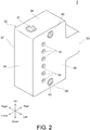
- FIG. 2 and FIG. 3 are perspective views showing the air purge unit 2 attached to the photoelectric sensor 1.
- FIG. 2 is a view of the air purge unit 2 viewed from the side of the front surface 34
- FIG. 3 is a view of the air purge unit 2 viewed from the side of the back surface 35. The configuration of the air purge unit 2 will be described with reference to FIG. 2 and FIG. 3 .
- the air purge unit 2 is a device that is attached to the side surface 13 or the side surface 14 of the photoelectric sensor 1 and blows air to the lens surface 11a of the photoelectric sensor 1.
- the air purge unit 2 includes a housing 30, an air supply port 31 provided in the housing 30, and air blow-out ports 32.
- the housing 10 has the front surface 34, the back surface 35, a side surface 36, a side surface 37, a top surface 38, and a bottom surface 39.
- the front surface 34 and the back surface 35 are located opposite to each other with the inside of the housing 10 interposed therebetween.
- the direction in which the front surface 34 is located is the front, and the direction in which the back surface 35 is located is the rear.
- the air purge unit 2 has the side surface 36 and the side surface 37 on the left and right.
- the side surface 36 and the side surface 37 are located opposite to each other with the inside of the housing 10 interposed therebetween.
- the air purge unit 2 has the top surface 38 and the bottom surface 39 at the top and bottom.
- the top surface 38 and the bottom surface 39 are located opposite to each other with the inside of the housing 10 interposed therebetween.
- the housing 30 has a shape that the upper and lower portions on the rear side are recessed inward, but the shape of the housing 30 is not limited thereto.
- the housing 30 may have a substantially rectangular parallelepiped shape as a whole without recessing the upper and lower portions on the rear side.
- the air supply port 31 is a portion to which an air supply device 50 (described later with reference to FIG. 4 ) for supplying air into the housing 30 is connected. As shown in FIG. 3 , the air supply ports 31 are provided on the top surface 38 and the back surface 35. Although not shown, the air supply port 31 is also provided on the bottom surface 39. By providing the air supply ports 31 at a plurality of positions of the housing 30 in this way, the air supply device 50 can be attached to an appropriate position depending on the location where the air purge unit 2 is arranged.
- the air purge unit 2 when the air purge unit 2 is installed in a space having a small width in the vertical direction, even if the air supply device 50 cannot be attached to the air supply port 31 on the top surface 38, the air supply device 50 can still be attached to the air supply port 31 on the back surface 35.
- the air supply device 50 connected to the air supply port 31 is a component that supplies the air received from an air supply source into the housing 30.
- the air supply device 50 will be described with reference to FIG. 4.
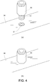
- (a) of FIG. 4 is a view showing a state before the air supply device 50 is attached to the air supply port 31, and
- (b) of FIG. 4 is a view showing a state after the air supply device 50 is attached to the air supply port 31.
- the air supply device 50 is formed in a tubular shape.
- One end (upper end in (a) of FIG. 4 ) of the air supply device 50 is connected to the air supply source, and the other end (lower end in (a) of FIG. 4 ) is connected to the air supply port 31 of the air purge unit 2.
- the air supply device 50 is detachably connected to the air supply port 31.
- the air supply device 50 has a screw portion 51 that is threaded at the lower end.
- the air supply port 31 of the air purge unit 2 is threaded on the inner surface thereof. Therefore, the air supply device 50 is connected to the air supply port 31 by screwing the screw portion 51 with the inner surface of the air supply port 31.
- the connection between the air supply device 50 and the air supply port 31 is not necessarily realized by screwing, and any method that can attach/detach the air supply device 50 to/from the air supply port 31 can be adopted.
- the air supply ports 31 are connected to the air supply ports 31 to which the air supply device 50 is not attached. All the three air supply ports 31 are connected to the air blow-out ports 32 via an air flow path formed inside the housing 30, the three air supply ports 31 are also connected to one another via the flow path. For this reason, when air is supplied from any one of the air supply ports 31, the air supplied from the other air supply ports 31 leaks out. Therefore, by attaching the plug to the air supply port 31 to which the air supply device 50 is not connected, leakage of the air is prevented.
- the air supply device 50 is connected to the air supply port 31 provided on the back surface 35, and the plugs 54 are attached to the air supply ports 31 provided on the top surface 38 and the bottom surface 39.
- a plurality of air blow-out ports 32 are provided and arranged on a side wall of the housing 30.
- the air supplied from the air supply port 31 is blown out from the air blow-out ports 32 through the flow path inside the housing 30.
- the air blown out from the air blow-out ports 32 may be blown out constantly, or may be blown out at regular time intervals.
- the air blow-out port 32 is a circular hole, but the shape is not limited thereto, and the air blow-out port 32 may be a polygonal hole such as a triangular hole or a quadrangular hole.
- a screw hole 40 is provided on the side wall of the housing 30.
- the screw hole 40 is threaded on the inner surface, and the screw for attaching the air purge unit 2 to the photoelectric sensor 1 is inserted thereinto.
- FIG. 5 is a view before attaching the air purge unit 2 to the photoelectric sensor 1.
- FIG. 5 shows the screw 60 and the air purge unit 2 for sandwiching the photoelectric sensor 1.
- the screw 60 is inserted into the communication hole 26 of the photoelectric sensor 1.
- the screw 60 is formed longer than the length of the communication hole 26 of the photoelectric sensor 1. Therefore, with the screw 60 inserted into the communication hole 26, the tip of the screw 60 protrudes from one end of the communication hole 26. After inserting the screw 60 into the communication hole 26, the tip of the screw 60 protruding from the communication hole 26 is screwed into the screw hole 40 of the air purge unit 2.
- the air purge unit 2 is screwed to the photoelectric sensor 1. Therefore, the air purge unit 2 is firmly attached to the photoelectric sensor 1, and the air purge unit 2 can be prevented from falling off from the photoelectric sensor 1.
- the method of attaching the air purge unit 2 is not limited to screwing.
- locking portions composed of a concave portion or a convex portion may be provided on the photoelectric sensor 1 and the air purge unit 2, and the air purge unit 2 may be attached via the locking portions.
- the air purge unit 2 may be attached by adhering the air purge unit 2 to the photoelectric sensor 1.
- an adjustment mechanism for adjusting the position and orientation of the photoelectric sensor 1 may be attached to the side surface 13 of the photoelectric sensor 1 where the air purge unit 2 is not attached.
- FIG. 6 is a perspective view showing the photoelectric sensor 1 with the air purge unit 2 attached.
- a plurality of air blow-out ports 32 are provided and arranged on the side wall of the air purge unit 2. Therefore, it is possible to blow air over a wide range of the lens surface 11a with the plurality of air blow-out ports 32 while reducing the size of each air blow-out port 32.
- the air purge unit 2 according to the present embodiment can remove contamination on the lens surface 11a of the photoelectric sensor 1 with a small air supply amount.
- the air blow-out ports 32 are provided close to the lens surface 11a. Therefore, the air blown out from the air blow-out ports 32 can reach the lens surface 11a without losing the momentum to efficiently remove the contamination adhering to the lens surface 11a.
- the plurality of air blow-out ports 32 are provided side by side in a straight line along the extending direction of the lens surface 11a.
- the plurality of air blow-out ports 32 are not necessarily provided in a straight line.
- the plurality of air blow-out ports 32 may be provided so that the adjacent air blow-out ports 32 are displaced from each other in the front-rear direction.
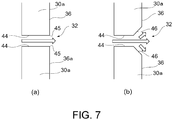
- FIG. 7 shows cross-sectional views of the air blow-out port 32 of the air purge unit 2 when the air blow-out port 32 is divided in the vertical direction shown in FIG. 2.
- (a) of FIG. 7 is a view showing an example of the air blow-out port 32
- (b) of FIG. 7 is a view showing another example of the air blow-out port 32.
- the arrows shown in FIG. 7 indicate the flow of air blown out from the air blow-out port 32.
- the inner surface 44 of the air blow-out port 32 shown in (a) of FIG. 7 intersects the surface (side surface 36) of the side wall 30a of the housing 30 at the corner 45.
- the inner surface 44 of the air blow-out port 32 and the side surface 36 intersect at the corner 45 at a substantially right angle. Therefore, as shown by the arrow, the air blown out from the air blow-out port 32 is blown out to the outside of the air purge unit 2 without spreading.
- the corner 46 where the inner surface 44 of the air blow-out port 32 and the side surface 36 shown in (b) of FIG. 7 intersect is chamfered.
- the corner 46 is C-chamfered (corner chamfered), and the diameter of the air blow-out port 32 increases from the inside toward the outside of the housing 30.
- the corner 46 is C-chamfered (corner chamfered), but the type of chamfering is not limited thereto.
- R-chamfering round chamfering or the like may be applied.
- An air purge unit (2) includes: a housing (30); an air supply port (31) for supplying air into the housing (30); and a plurality of air blow-out ports (32) arranged on a side wall (30a) of the housing (30) for blowing the air to a lens surface (11a) of a photoelectric sensor (1).
Landscapes
- Physics & Mathematics (AREA)
- General Physics & Mathematics (AREA)
- Engineering & Computer Science (AREA)
- Life Sciences & Earth Sciences (AREA)
- General Life Sciences & Earth Sciences (AREA)
- Geophysics (AREA)
- Computer Networks & Wireless Communication (AREA)
- Radar, Positioning & Navigation (AREA)
- Remote Sensing (AREA)
- Optics & Photonics (AREA)
- Optical Measuring Cells (AREA)
- Cleaning In General (AREA)
- Switches Operated By Changes In Physical Conditions (AREA)
- Photometry And Measurement Of Optical Pulse Characteristics (AREA)
Abstract
Description
- The invention relates to an air purge unit.
- Conventionally, there is a photoelectric sensor that detects whether a workpiece is present by using light. The photoelectric sensor performs various detections by, for example, emitting detection light toward the workpiece and then analyzing the light transmitted through the workpiece or reflected from the workpiece (for example, Patent Document 1).
- The photoelectric sensor may be installed in an environment where machining is performed. In such an environment, contamination such as dust and processing oil may adhere to a lens surface of the photoelectric sensor through which light passes, and the amount of light passing through the lens surface may decrease. Then, detection of the workpiece may not be performed properly. Therefore, a method is adopted, which attaches an air purge unit that blows air to the lens surface to the photoelectric sensor to prevent contamination from adhering to the lens surface. For example, as shown in
FIG. 8 , anair purge unit 2 provided with an elongated air blow-outport 60 along alens surface 11a may be attached to aphotoelectric sensor 1 to remove contamination on thelens surface 11a. - [Patent Document 1]
Japanese Laid-Open No. 2011-077050 - However, when contamination that is difficult to remove adheres to the lens surface, it is necessary to blow out air having a high flow velocity from the air blow-out part. In this case, it is necessary to supply a large amount of air to the air purge unit, which causes problems such as an increase in electric power for supplying air.
- Therefore, the invention provides an air purge unit that can remove contamination on the lens surface of the photoelectric sensor with a small air supply amount.
- An air purge unit according to one aspect of the invention includes: a housing; an air supply port for supplying air into the housing; and a plurality of air blow-out ports arranged on a side wall of the housing for blowing the air to a lens surface of a photoelectric sensor.
- According to this aspect, the plurality of air blow-out ports are provided and arranged on the side wall of the air purge unit. Therefore, it is possible to blow air over a wide range of the lens surface with the plurality of air blow-out ports while reducing the size of each air blow-out port. By reducing the size of the air blow-out port, the flow velocity of the air blown from each air blow-out port of the air purge unit increases as compared with the conventional air purge unit provided with one large air blow-out port. That is, the air purge unit according to the invention can remove contamination on the lens surface of the photoelectric sensor with a small air supply amount.
- In the above aspect, the plurality of air blow-out ports may be provided side by side in a straight line.
- In the above aspect, the plurality of air blow-out ports may be provided along an extending direction of the lens surface.
- According to this aspect, the air blown out from the air blow-out ports of the air purge unit easily hits the lens surface, and the contamination adhering to the lens surface is efficiently removed.
- In the above aspect, the plurality of air blow-out ports may be circular holes.
- In the above aspect, corners connecting inner surfaces of the plurality of air blow-out ports and a side wall surface of the housing may be chamfered.
- According to this aspect, air is blown out to spread from the air blow-out port. That is, since the air blown out from the air blow-out port hits a wide range of the lens surface, it is possible to remove contamination adhering over a wide range of the lens surface.
- According to the invention, it is possible to provide an air purge unit that can remove contamination on a lens surface of a photoelectric sensor with a small air supply amount.
-
-
FIG. 1 is a perspective view showing the appearance of a photoelectric sensor according to the present embodiment. -
FIG. 2 is a perspective view showing the appearance of the air purge unit according to the present embodiment. -
FIG. 3 is a perspective view showing the appearance of the air purge unit according to the present embodiment. - (a) and (b) of
FIG. 4 are views showing how the air supply device is attached to the air supply port, wherein (a) ofFIG. 4 shows a state before attachment and (b) ofFIG. 4 shows a state after attachment. -
FIG. 5 is a view showing how the air purge unit is attached to the photoelectric sensor. -
FIG. 6 is a view showing the photoelectric sensor with the air purge unit attached. - (a) and (b) of
FIG. 7 are cross-sectional views of the air purge unit showing the shape of the air blow-out port. -
FIG. 8 is a view showing the photoelectric sensor with the conventional air purge unit attached. - Embodiments of the invention will be described with reference to the accompanying drawings. In each drawing, parts having the same reference numerals have the same or similar configurations.
-
FIG. 1 is a perspective view showing the appearance of aphotoelectric sensor 1 according to the present embodiment. First, thephotoelectric sensor 1 with an air purge unit attached will be described with reference toFIG. 1 . Thephotoelectric sensor 1 detects whether an object is present in a detection region and a surface state of the object by using light. There are several detection methods using thephotoelectric sensor 1. For example, there is a method, in which two photoelectric sensors are prepared, onephotoelectric sensor 1 is used as a light projector that emits light and the otherphotoelectric sensor 1 is used as a light receiver that receives light, and the detection is performed by analyzing the light received by the light receiver. If an object exists between the light projector and the light receiver, the amount of light received by the light receiver decreases so thephotoelectric sensor 1 analyzes this decrease amount to detect whether an object is present. Thephotoelectric sensor 1 used in the detection method is called a transmissive type. - Further, as another detection method, there is a method, which performs detection by using a photoelectric sensor in which the light projector and the light receiver are integrated. In the method, light is emitted from the
photoelectric sensor 1 toward a reflective plate or an object, and the reflected light is received by the samephotoelectric sensor 1. Thephotoelectric sensor 1 detects whether an object is present and a surface state of the object by analyzing the received light. Such a photoelectric sensor that functions as both the light projector and the light receiver is called a reflective type. In this specification, the reflectivephotoelectric sensor 1 will be described as an example, but thephotoelectric sensor 1 to which the invention is applied may be a transmissive photoelectric sensor. -
FIG. 1 shows thephotoelectric sensor 1 in a state where the air purge unit is not attached. Thephotoelectric sensor 1 includes ahousing 10, awindow 20, and acable 21. - The
housing 10 houses various parts such as a light projecting element and a light receiving element included in thephotoelectric sensor 1, and protects them from impact and contamination. Thehousing 10 may be made of, for example, metal or resin. Thehousing 10 has afront surface 11, aback surface 12, aside surface 13, aside surface 14, atop surface 15, and abottom surface 16. Thefront surface 11 is a surface located on the traveling direction side of the projected light, and forms a frame surrounding thelens surface 11a through which light is transmitted. Theback surface 12 is located at a position opposite to thefront surface 11 with the inside of thehousing 10 interposed therebetween. Further, when the direction in which thefront surface 11 is located is the front and the direction in which theback surface 12 is located is the rear, thehousing 10 has theside surfaces side surface 13 and theside surface 14 are located opposite to each other with the inside of thehousing 10 interposed therebetween. Further, thehousing 10 has thetop surface 15 and thebottom surface 16 at the top and bottom. Similar to the side surfaces 13 and 14, thetop surface 15 and thebottom surface 16 are located opposite to each other with the inside of thehousing 10 interposed therebetween. - The
front surface 11 is a surface surrounding thelens surface 11a which transmits light. Thelens surface 11a is formed of a member that transmits light, and transmits the light emitted from a light projecting unit (not shown) included in thephotoelectric sensor 1. Further, thelens surface 11a transmits light that is reflected from a detection target and incident on a light receiving unit (not shown) included in thephotoelectric sensor 1. Thelens surface 11a may be made of, for example, transparent resin or glass. - The light projecting unit is a unit that emits light to the detection region, and is composed of a light projecting element and a light projecting lens. The light projecting element is an element that emits light, and may be, for example, a laser or a light emitting diode. The light projecting lens converts the light generated from the light projecting element into parallel light. A part of the projecting lens may be exposed to the outside of the
housing 10, and for example, thelens surface 11a shown inFIG. 1 may be the surface of the light projecting lens. - The light receiving unit is a unit that detects incident light, and includes a light receiving element and a light receiving lens. The light receiving element is an element that detects light, and may be, for example, a photodiode or the like. The light receiving lens is a lens that forms an image of the light incident from the detection region on the light receiving element. A part of the light receiving lens may be exposed to the outside of the
housing 10, and for example, thelens surface 11a shown inFIG. 1 may be the surface of the light receiving lens. - The
housing 10 has acommunication hole 26. Thecommunication hole 26 is a hole provided across the inside of thehousing 10 so as to communicate theside surface 13 and theside surface 14. In the present embodiment, thehousing 10 has twocommunication holes 26, which are respectively provided in the upper part and the lower part of thehousing 10. The communication holes 26 are used when connecting the air purge unit described later to thephotoelectric sensor 1. Specifically, the air purge unit is screwed to thephotoelectric sensor 1 by inserting a screw from one end of thecommunication hole 26 and screwing the tip of the screw protruding from the other end into a screw hole provided in the air purge unit. - The
window 20 is located to cover an indicator lamp (not shown) provided on the upper part of thephotoelectric sensor 1, and protects the indicator lamp from impact and contamination. Thewindow 20 is preferably made of transparent resin or glass so that the user can visually recognize the indicator lamp from the outside. The indicator lamp outputs the operating status of thephotoelectric sensor 1 by emitting light. The operating status may include, for example, the power supply status and the detection status of thephotoelectric sensor 1. The indicator lamp may be composed of a light emitting element such as a light emitting diode. The indicator lamp may be turned on, for example, when the power of thephotoelectric sensor 1 is turned on or when thephotoelectric sensor 1 detects a workpiece. - The
cable 21 transmits the electric power supplied from a power supply to thephotoelectric sensor 1. Further, thecable 21 may connect thephotoelectric sensor 1 to an amplifier unit and transmit a detection result of thephotoelectric sensor 1. At least one of the power supply and the amplifier unit may be built in thephotoelectric sensor 1. -
FIG. 2 andFIG. 3 are perspective views showing theair purge unit 2 attached to thephotoelectric sensor 1.FIG. 2 is a view of theair purge unit 2 viewed from the side of thefront surface 34, andFIG. 3 is a view of theair purge unit 2 viewed from the side of theback surface 35. The configuration of theair purge unit 2 will be described with reference toFIG. 2 andFIG. 3 . - The
air purge unit 2 is a device that is attached to theside surface 13 or theside surface 14 of thephotoelectric sensor 1 and blows air to thelens surface 11a of thephotoelectric sensor 1. Theair purge unit 2 includes ahousing 30, anair supply port 31 provided in thehousing 30, and air blow-outports 32. - The
housing 10 has thefront surface 34, theback surface 35, aside surface 36, aside surface 37, atop surface 38, and abottom surface 39. As shown inFIG. 2 , thefront surface 34 and theback surface 35 are located opposite to each other with the inside of thehousing 10 interposed therebetween. The direction in which thefront surface 34 is located is the front, and the direction in which theback surface 35 is located is the rear. Further, theair purge unit 2 has theside surface 36 and theside surface 37 on the left and right. Theside surface 36 and theside surface 37 are located opposite to each other with the inside of thehousing 10 interposed therebetween. Furthermore, theair purge unit 2 has thetop surface 38 and thebottom surface 39 at the top and bottom. Thetop surface 38 and thebottom surface 39 are located opposite to each other with the inside of thehousing 10 interposed therebetween. - In the present embodiment, the
housing 30 has a shape that the upper and lower portions on the rear side are recessed inward, but the shape of thehousing 30 is not limited thereto. For example, thehousing 30 may have a substantially rectangular parallelepiped shape as a whole without recessing the upper and lower portions on the rear side. - The
air supply port 31 is a portion to which an air supply device 50 (described later with reference toFIG. 4 ) for supplying air into thehousing 30 is connected. As shown inFIG. 3 , theair supply ports 31 are provided on thetop surface 38 and theback surface 35. Although not shown, theair supply port 31 is also provided on thebottom surface 39. By providing theair supply ports 31 at a plurality of positions of thehousing 30 in this way, theair supply device 50 can be attached to an appropriate position depending on the location where theair purge unit 2 is arranged. For example, when theair purge unit 2 is installed in a space having a small width in the vertical direction, even if theair supply device 50 cannot be attached to theair supply port 31 on thetop surface 38, theair supply device 50 can still be attached to theair supply port 31 on theback surface 35. - The
air supply device 50 connected to theair supply port 31 is a component that supplies the air received from an air supply source into thehousing 30. Here, theair supply device 50 will be described with reference toFIG. 4. (a) ofFIG. 4 is a view showing a state before theair supply device 50 is attached to theair supply port 31, and (b) ofFIG. 4 is a view showing a state after theair supply device 50 is attached to theair supply port 31. As shown in (a) ofFIG. 4 , theair supply device 50 is formed in a tubular shape. One end (upper end in (a) ofFIG. 4 ) of theair supply device 50 is connected to the air supply source, and the other end (lower end in (a) ofFIG. 4 ) is connected to theair supply port 31 of theair purge unit 2. Theair supply device 50 is detachably connected to theair supply port 31. - As shown in (a) of
FIG. 4 , theair supply device 50 has ascrew portion 51 that is threaded at the lower end. On the other hand, theair supply port 31 of theair purge unit 2 is threaded on the inner surface thereof. Therefore, theair supply device 50 is connected to theair supply port 31 by screwing thescrew portion 51 with the inner surface of theair supply port 31. The connection between theair supply device 50 and theair supply port 31 is not necessarily realized by screwing, and any method that can attach/detach theair supply device 50 to/from theair supply port 31 can be adopted. - The description will be continued by reverting to
FIG. 2 andFIG. 3 . Among the threeair supply ports 31 provided in thehousing 30, plugs are attached to theair supply ports 31 to which theair supply device 50 is not attached. All the threeair supply ports 31 are connected to the air blow-outports 32 via an air flow path formed inside thehousing 30, the threeair supply ports 31 are also connected to one another via the flow path. For this reason, when air is supplied from any one of theair supply ports 31, the air supplied from the otherair supply ports 31 leaks out. Therefore, by attaching the plug to theair supply port 31 to which theair supply device 50 is not connected, leakage of the air is prevented. For example, in theair purge unit 2 shown inFIG. 5 , theair supply device 50 is connected to theair supply port 31 provided on theback surface 35, and theplugs 54 are attached to theair supply ports 31 provided on thetop surface 38 and thebottom surface 39. - A plurality of air blow-out
ports 32 are provided and arranged on a side wall of thehousing 30. The air supplied from theair supply port 31 is blown out from the air blow-outports 32 through the flow path inside thehousing 30. The air blown out from the air blow-outports 32 may be blown out constantly, or may be blown out at regular time intervals. Further, in the present embodiment, the air blow-outport 32 is a circular hole, but the shape is not limited thereto, and the air blow-outport 32 may be a polygonal hole such as a triangular hole or a quadrangular hole. - A
screw hole 40 is provided on the side wall of thehousing 30. Thescrew hole 40 is threaded on the inner surface, and the screw for attaching theair purge unit 2 to thephotoelectric sensor 1 is inserted thereinto. - A method of attaching the
air purge unit 2 to thephotoelectric sensor 1 will be described with reference toFIG. 5. FIG. 5 is a view before attaching theair purge unit 2 to thephotoelectric sensor 1.FIG. 5 shows thescrew 60 and theair purge unit 2 for sandwiching thephotoelectric sensor 1. First, thescrew 60 is inserted into thecommunication hole 26 of thephotoelectric sensor 1. Thescrew 60 is formed longer than the length of thecommunication hole 26 of thephotoelectric sensor 1. Therefore, with thescrew 60 inserted into thecommunication hole 26, the tip of thescrew 60 protrudes from one end of thecommunication hole 26. After inserting thescrew 60 into thecommunication hole 26, the tip of thescrew 60 protruding from thecommunication hole 26 is screwed into thescrew hole 40 of theair purge unit 2. - As described above, the
air purge unit 2 is screwed to thephotoelectric sensor 1. Therefore, theair purge unit 2 is firmly attached to thephotoelectric sensor 1, and theair purge unit 2 can be prevented from falling off from thephotoelectric sensor 1. The method of attaching theair purge unit 2 is not limited to screwing. For example, locking portions composed of a concave portion or a convex portion may be provided on thephotoelectric sensor 1 and theair purge unit 2, and theair purge unit 2 may be attached via the locking portions. Further, theair purge unit 2 may be attached by adhering theair purge unit 2 to thephotoelectric sensor 1. Further, an adjustment mechanism for adjusting the position and orientation of thephotoelectric sensor 1 may be attached to theside surface 13 of thephotoelectric sensor 1 where theair purge unit 2 is not attached. -
FIG. 6 is a perspective view showing thephotoelectric sensor 1 with theair purge unit 2 attached. As shown inFIG. 6 , a plurality of air blow-outports 32 are provided and arranged on the side wall of theair purge unit 2. Therefore, it is possible to blow air over a wide range of thelens surface 11a with the plurality of air blow-outports 32 while reducing the size of each air blow-outport 32. By reducing the size of the air blow-outport 32, the flow velocity of the air blown from each air blow-outport 32 of theair purge unit 2 increases as compared with the conventional air purge unit provided with one large air blow-out port. That is, theair purge unit 2 according to the present embodiment can remove contamination on thelens surface 11a of thephotoelectric sensor 1 with a small air supply amount. - Further, the air blow-out
ports 32 are provided close to thelens surface 11a. Therefore, the air blown out from the air blow-outports 32 can reach thelens surface 11a without losing the momentum to efficiently remove the contamination adhering to thelens surface 11a. - In addition, in the present embodiment, the plurality of air blow-out
ports 32 are provided side by side in a straight line along the extending direction of thelens surface 11a. However, the plurality of air blow-outports 32 are not necessarily provided in a straight line. For example, the plurality of air blow-outports 32 may be provided so that the adjacent air blow-outports 32 are displaced from each other in the front-rear direction. - Next, the shape of the air blow-out
port 32 will be described with reference toFIG. 7. FIG. 7 shows cross-sectional views of the air blow-outport 32 of theair purge unit 2 when the air blow-outport 32 is divided in the vertical direction shown in FIG. 2. (a) ofFIG. 7 is a view showing an example of the air blow-outport 32, and (b) ofFIG. 7 is a view showing another example of the air blow-outport 32. The arrows shown inFIG. 7 indicate the flow of air blown out from the air blow-outport 32. - First, the air blow-out
port 32 shown in (a) ofFIG. 7 will be described. Theinner surface 44 of the air blow-outport 32 shown in (a) ofFIG. 7 intersects the surface (side surface 36) of theside wall 30a of thehousing 30 at thecorner 45. Theinner surface 44 of the air blow-outport 32 and theside surface 36 intersect at thecorner 45 at a substantially right angle. Therefore, as shown by the arrow, the air blown out from the air blow-outport 32 is blown out to the outside of theair purge unit 2 without spreading. - On the other hand, the
corner 46 where theinner surface 44 of the air blow-outport 32 and theside surface 36 shown in (b) ofFIG. 7 intersect is chamfered. In the present embodiment, thecorner 46 is C-chamfered (corner chamfered), and the diameter of the air blow-outport 32 increases from the inside toward the outside of thehousing 30. By chamfering thecorner 46 connecting theinner surface 44 of the air blow-outport 32 and theside surface 36 in this way, the air passing through the air blow-outport 32 is oriented to spread. Therefore, the air blown out from the air blow-outport 32 can be blown over a wide range of thelens surface 11a to efficiently remove contamination. - In the present embodiment, the
corner 46 is C-chamfered (corner chamfered), but the type of chamfering is not limited thereto. For example, R-chamfering (round chamfering) or the like may be applied. - The embodiments described above are provided to facilitate the understanding of the invention, and are not intended to interpret the invention in a limiting manner. Each element included in the embodiment and its arrangement, material, condition, shape, size, etc. are not limited to those exemplified, and can be changed as appropriate. In addition, the configurations shown in different embodiments can be partially replaced or combined.
- An air purge unit (2) includes: a housing (30); an air supply port (31) for supplying air into the housing (30); and a plurality of air blow-out ports (32) arranged on a side wall (30a) of the housing (30) for blowing the air to a lens surface (11a) of a photoelectric sensor (1).
- 1 ... photoelectric sensor, 2 ... air purge unit, 10 ... housing, 11 ... front surface, 11a ... lens surface, 12 ... back surface, 13 ... side surface, 14 ... side surface, 15 ... top surface, 16 ... bottom surface, 20 ... window, 21 ... cable, 26 ... communication hole, 30 ... housing, 30a ... side wall, 31 ... air supply port, 32 ... air blow-out port, 34 ... front surface, 35 ... back surface, 36 ... side surface, 37 ... side surface, 38 ... top surface, 39 ... bottom surface, 40 ... screw hole, 44 ... inner surface, 45 ... corner, 46 ... corner, 50 ... air supply device, 51 ... screw portion, 54 ... plug, 60 ... air blow-out port
Claims (5)
- An air purge unit, comprising:a housing;an air supply port for supplying air into the housing; anda plurality of air blow-out ports arranged on a side wall of the housing for blowing the air to a lens surface of a photoelectric sensor.
- The air purge unit according to claim 1, wherein the plurality of air blow-out ports are provided side by side in a straight line.
- The air purge unit according to claim 1 or 2, wherein the plurality of air blow-out ports are provided along an extending direction of the lens surface.
- The air purge unit according to any one of claims 1 to 3, wherein the plurality of air blow-out ports are circular holes.
- The air purge unit according to any one of claims 1 to 4, wherein corners connecting inner surfaces of the plurality of air blow-out ports and a side wall surface of the housing are chamfered.
Applications Claiming Priority (2)
| Application Number | Priority Date | Filing Date | Title |
|---|---|---|---|
| JP2019032760A JP7003946B2 (en) | 2019-02-26 | 2019-02-26 | Air purge unit |
| PCT/JP2020/005964 WO2020175203A1 (en) | 2019-02-26 | 2020-02-17 | Air purge unit |
Publications (3)
| Publication Number | Publication Date |
|---|---|
| EP3932571A1 true EP3932571A1 (en) | 2022-01-05 |
| EP3932571A4 EP3932571A4 (en) | 2022-12-21 |
| EP3932571B1 EP3932571B1 (en) | 2024-05-01 |
Family
ID=72239797
Family Applications (1)
| Application Number | Title | Priority Date | Filing Date |
|---|---|---|---|
| EP20763761.2A Active EP3932571B1 (en) | 2019-02-26 | 2020-02-17 | Air purge unit |
Country Status (6)
| Country | Link |
|---|---|
| US (1) | US20220091298A1 (en) |
| EP (1) | EP3932571B1 (en) |
| JP (1) | JP7003946B2 (en) |
| KR (1) | KR20210092820A (en) |
| CN (1) | CN113272078A (en) |
| WO (1) | WO2020175203A1 (en) |
Families Citing this family (3)
| Publication number | Priority date | Publication date | Assignee | Title |
|---|---|---|---|---|
| JP7429296B2 (en) | 2020-08-12 | 2024-02-07 | 三菱重工業株式会社 | Turbine vanes and steam turbines |
| US12372620B2 (en) * | 2021-12-15 | 2025-07-29 | Ford Global Technologies, Llc | Sensor assembly with deflector |
| JP2024101646A (en) * | 2023-01-18 | 2024-07-30 | 住友金属鉱山株式会社 | Cathodic finisher and thickness measuring device used therein |
Family Cites Families (23)
| Publication number | Priority date | Publication date | Assignee | Title |
|---|---|---|---|---|
| JPS5125721Y2 (en) * | 1971-08-31 | 1976-06-30 | ||
| JPS59109311U (en) * | 1983-01-11 | 1984-07-23 | オムロン株式会社 | Photoelectric switch lens dirt prevention device |
| JPH0736027U (en) * | 1993-12-10 | 1995-07-04 | 株式会社キーエンス | Photoelectric detector purifier |
| JPH10202576A (en) * | 1997-01-14 | 1998-08-04 | Shibaura Eng Works Co Ltd | Linear moving robot and air purge unit |
| US5879626A (en) * | 1997-07-30 | 1999-03-09 | Allen-Bradley Company, Llc | Photoelectric sensor having dust removal apparatus |
| US6890080B2 (en) * | 2002-01-25 | 2005-05-10 | Ircon, Inc. | Air purge system for optical sensor |
| US8898852B2 (en) * | 2010-08-04 | 2014-12-02 | Honeywell International Inc. | Air burst to clear detection window |
| CN201903499U (en) * | 2010-10-28 | 2011-07-20 | 松下电工电子材料(苏州)有限公司 | Appearance inspection machine capable of automatic scavenging |
| JP5194101B2 (en) | 2010-12-03 | 2013-05-08 | 株式会社キーエンス | Photoelectric switch |
| US9796359B2 (en) * | 2012-02-23 | 2017-10-24 | The Raymond Corporation | Method and apparatus for removing and preventing lens surface contamination on a vehicle lens |
| CN202851062U (en) * | 2012-10-26 | 2013-04-03 | 深圳市幻方科技发展有限公司 | Protective cover capable of preventing one-way vent valve from bearing reverse impact |
| JP2014201150A (en) * | 2013-04-03 | 2014-10-27 | クラリオン株式会社 | On-vehicle imaging device, dirt preventing method of optical member, and camera module |
| CN103557905B (en) * | 2013-11-20 | 2016-02-24 | 中环天仪股份有限公司 | A kind of high-temperature radar stock rod |
| US10215982B2 (en) * | 2013-11-27 | 2019-02-26 | Halliburton Energy Services, Inc. | Air curtain generator for optical sensing devices |
| US9217864B2 (en) * | 2014-03-28 | 2015-12-22 | Richard Bell | Automatic camera lens cleaning system |
| WO2017080614A1 (en) * | 2015-11-13 | 2017-05-18 | Fico Transpar, S.A. | System for cleaning a vehicle-mounted sensor |
| FR3027007B1 (en) * | 2014-10-10 | 2017-12-08 | Valeo Systemes Dessuyage | DEVICE FOR CLEANING A DRIVING CAMERA FOR DRIVING A MOTOR VEHICLE |
| TWI604257B (en) * | 2016-10-05 | 2017-11-01 | Zheng-Zhi Lin | Car camera lens prevent water mirror device |
| US20180354469A1 (en) * | 2017-06-08 | 2018-12-13 | Ford Global Technologies, Llc | Cleaning vehicle sensors |
| CN207325495U (en) * | 2017-08-24 | 2018-05-08 | 中国汽车工业工程有限公司 | A kind of carbon dioxide snowflake cleaning nozzle device |
| US11738720B2 (en) * | 2017-08-30 | 2023-08-29 | Koito Manufacturing Co., Ltd. | Vehicle cleaner unit and vehicle provided with vehicle cleaner unit |
| DE102017221530A1 (en) * | 2017-11-30 | 2019-06-06 | Robert Bosch Gmbh | Device designed for environment detection and method for cleaning a cover of such a device |
| US11097695B2 (en) * | 2018-10-30 | 2021-08-24 | Waymo Llc | Non-contact cleaning system |
-
2019
- 2019-02-26 JP JP2019032760A patent/JP7003946B2/en active Active
-
2020
- 2020-02-17 KR KR1020217019473A patent/KR20210092820A/en not_active Ceased
- 2020-02-17 WO PCT/JP2020/005964 patent/WO2020175203A1/en not_active Ceased
- 2020-02-17 US US17/424,882 patent/US20220091298A1/en active Pending
- 2020-02-17 EP EP20763761.2A patent/EP3932571B1/en active Active
- 2020-02-17 CN CN202080008329.6A patent/CN113272078A/en active Pending
Also Published As
| Publication number | Publication date |
|---|---|
| JP7003946B2 (en) | 2022-01-21 |
| US20220091298A1 (en) | 2022-03-24 |
| WO2020175203A1 (en) | 2020-09-03 |
| CN113272078A (en) | 2021-08-17 |
| EP3932571A4 (en) | 2022-12-21 |
| EP3932571B1 (en) | 2024-05-01 |
| KR20210092820A (en) | 2021-07-26 |
| JP2020136246A (en) | 2020-08-31 |
Similar Documents
| Publication | Publication Date | Title |
|---|---|---|
| US20220091298A1 (en) | Air purge unit | |
| ES2260357T3 (en) | FIRE DETECTOR. | |
| US11215699B2 (en) | Lamp device | |
| JP7006639B2 (en) | Adjustment mechanism | |
| EP3463980A1 (en) | A lamp assembly for a vehicle | |
| US10739582B2 (en) | Air purge unit | |
| TWI421471B (en) | Laser head with laser head | |
| US9307602B2 (en) | Illumination system | |
| CN101770040B (en) | Multi-optical axis photoelectric sensor | |
| TW200712597A (en) | Optical module of a light source module and a sensor module positioned on a frame | |
| US20050201096A1 (en) | Object detecting apparatus for vehicle | |
| US7869048B2 (en) | Photoelectonic sensor | |
| KR101148436B1 (en) | Optical mouse and method for removing contaminants in an optical mouse | |
| EP4556422A1 (en) | Housing of a yarn clearer and corresponding method of assembly | |
| US11112299B2 (en) | Small photoelectric sensor | |
| US10184218B1 (en) | Marker light | |
| EP2977275A1 (en) | Rain detection device | |
| JP6999093B2 (en) | Sensor | |
| JP2002243543A (en) | Photoelectric sensor | |
| KR101886253B1 (en) | Aeronautical lighting system having the function for fault diagnosis according to temperature variation | |
| JP4805060B2 (en) | Flash lamp | |
| JP2026026375A (en) | Sensor Device | |
| KR101886251B1 (en) | Integrated lighting apparatus used in taxiing and landing of aircraft | |
| JP6237744B2 (en) | projector | |
| JP2011027532A (en) | Photoelectric sensor |
Legal Events
| Date | Code | Title | Description |
|---|---|---|---|
| STAA | Information on the status of an ep patent application or granted ep patent |
Free format text: STATUS: THE INTERNATIONAL PUBLICATION HAS BEEN MADE |
|
| PUAI | Public reference made under article 153(3) epc to a published international application that has entered the european phase |
Free format text: ORIGINAL CODE: 0009012 |
|
| STAA | Information on the status of an ep patent application or granted ep patent |
Free format text: STATUS: REQUEST FOR EXAMINATION WAS MADE |
|
| 17P | Request for examination filed |
Effective date: 20210712 |
|
| AK | Designated contracting states |
Kind code of ref document: A1 Designated state(s): AL AT BE BG CH CY CZ DE DK EE ES FI FR GB GR HR HU IE IS IT LI LT LU LV MC MK MT NL NO PL PT RO RS SE SI SK SM TR |
|
| DAV | Request for validation of the european patent (deleted) | ||
| DAX | Request for extension of the european patent (deleted) | ||
| A4 | Supplementary search report drawn up and despatched |
Effective date: 20221122 |
|
| RIC1 | Information provided on ipc code assigned before grant |
Ipc: H01H 35/00 20060101ALI20221116BHEP Ipc: B08B 5/02 20060101AFI20221116BHEP |
|
| GRAP | Despatch of communication of intention to grant a patent |
Free format text: ORIGINAL CODE: EPIDOSNIGR1 |
|
| STAA | Information on the status of an ep patent application or granted ep patent |
Free format text: STATUS: GRANT OF PATENT IS INTENDED |
|
| RIC1 | Information provided on ipc code assigned before grant |
Ipc: G02B 27/00 20060101ALI20231211BHEP Ipc: G01S 7/497 20060101ALI20231211BHEP Ipc: H01H 35/00 20060101ALI20231211BHEP Ipc: B05B 1/14 20060101ALI20231211BHEP Ipc: B08B 5/02 20060101AFI20231211BHEP |
|
| INTG | Intention to grant announced |
Effective date: 20240117 |
|
| GRAS | Grant fee paid |
Free format text: ORIGINAL CODE: EPIDOSNIGR3 |
|
| GRAA | (expected) grant |
Free format text: ORIGINAL CODE: 0009210 |
|
| STAA | Information on the status of an ep patent application or granted ep patent |
Free format text: STATUS: THE PATENT HAS BEEN GRANTED |
|
| AK | Designated contracting states |
Kind code of ref document: B1 Designated state(s): AL AT BE BG CH CY CZ DE DK EE ES FI FR GB GR HR HU IE IS IT LI LT LU LV MC MK MT NL NO PL PT RO RS SE SI SK SM TR |
|
| REG | Reference to a national code |
Ref country code: GB Ref legal event code: FG4D |
|
| REG | Reference to a national code |
Ref country code: CH Ref legal event code: EP |
|
| REG | Reference to a national code |
Ref country code: IE Ref legal event code: FG4D |
|
| REG | Reference to a national code |
Ref country code: DE Ref legal event code: R096 Ref document number: 602020030203 Country of ref document: DE |
|
| REG | Reference to a national code |
Ref country code: LT Ref legal event code: MG9D |
|
| REG | Reference to a national code |
Ref country code: NL Ref legal event code: MP Effective date: 20240501 |
|
| PG25 | Lapsed in a contracting state [announced via postgrant information from national office to epo] |
Ref country code: IS Free format text: LAPSE BECAUSE OF FAILURE TO SUBMIT A TRANSLATION OF THE DESCRIPTION OR TO PAY THE FEE WITHIN THE PRESCRIBED TIME-LIMIT Effective date: 20240901 |
|
| PG25 | Lapsed in a contracting state [announced via postgrant information from national office to epo] |
Ref country code: BG Free format text: LAPSE BECAUSE OF FAILURE TO SUBMIT A TRANSLATION OF THE DESCRIPTION OR TO PAY THE FEE WITHIN THE PRESCRIBED TIME-LIMIT Effective date: 20240501 |
|
| PG25 | Lapsed in a contracting state [announced via postgrant information from national office to epo] |
Ref country code: HR Free format text: LAPSE BECAUSE OF FAILURE TO SUBMIT A TRANSLATION OF THE DESCRIPTION OR TO PAY THE FEE WITHIN THE PRESCRIBED TIME-LIMIT Effective date: 20240501 Ref country code: FI Free format text: LAPSE BECAUSE OF FAILURE TO SUBMIT A TRANSLATION OF THE DESCRIPTION OR TO PAY THE FEE WITHIN THE PRESCRIBED TIME-LIMIT Effective date: 20240501 |
|
| PG25 | Lapsed in a contracting state [announced via postgrant information from national office to epo] |
Ref country code: GR Free format text: LAPSE BECAUSE OF FAILURE TO SUBMIT A TRANSLATION OF THE DESCRIPTION OR TO PAY THE FEE WITHIN THE PRESCRIBED TIME-LIMIT Effective date: 20240802 |
|
| PG25 | Lapsed in a contracting state [announced via postgrant information from national office to epo] |
Ref country code: PT Free format text: LAPSE BECAUSE OF FAILURE TO SUBMIT A TRANSLATION OF THE DESCRIPTION OR TO PAY THE FEE WITHIN THE PRESCRIBED TIME-LIMIT Effective date: 20240902 |
|
| REG | Reference to a national code |
Ref country code: AT Ref legal event code: MK05 Ref document number: 1681637 Country of ref document: AT Kind code of ref document: T Effective date: 20240501 |
|
| PG25 | Lapsed in a contracting state [announced via postgrant information from national office to epo] |
Ref country code: NL Free format text: LAPSE BECAUSE OF FAILURE TO SUBMIT A TRANSLATION OF THE DESCRIPTION OR TO PAY THE FEE WITHIN THE PRESCRIBED TIME-LIMIT Effective date: 20240501 |
|
| PG25 | Lapsed in a contracting state [announced via postgrant information from national office to epo] |
Ref country code: ES Free format text: LAPSE BECAUSE OF FAILURE TO SUBMIT A TRANSLATION OF THE DESCRIPTION OR TO PAY THE FEE WITHIN THE PRESCRIBED TIME-LIMIT Effective date: 20240501 |
|
| PG25 | Lapsed in a contracting state [announced via postgrant information from national office to epo] |
Ref country code: AT Free format text: LAPSE BECAUSE OF FAILURE TO SUBMIT A TRANSLATION OF THE DESCRIPTION OR TO PAY THE FEE WITHIN THE PRESCRIBED TIME-LIMIT Effective date: 20240501 |
|
| PG25 | Lapsed in a contracting state [announced via postgrant information from national office to epo] |
Ref country code: PL Free format text: LAPSE BECAUSE OF FAILURE TO SUBMIT A TRANSLATION OF THE DESCRIPTION OR TO PAY THE FEE WITHIN THE PRESCRIBED TIME-LIMIT Effective date: 20240501 |
|
| PG25 | Lapsed in a contracting state [announced via postgrant information from national office to epo] |
Ref country code: LV Free format text: LAPSE BECAUSE OF FAILURE TO SUBMIT A TRANSLATION OF THE DESCRIPTION OR TO PAY THE FEE WITHIN THE PRESCRIBED TIME-LIMIT Effective date: 20240501 |
|
| PG25 | Lapsed in a contracting state [announced via postgrant information from national office to epo] |
Ref country code: PT Free format text: LAPSE BECAUSE OF FAILURE TO SUBMIT A TRANSLATION OF THE DESCRIPTION OR TO PAY THE FEE WITHIN THE PRESCRIBED TIME-LIMIT Effective date: 20240902 Ref country code: PL Free format text: LAPSE BECAUSE OF FAILURE TO SUBMIT A TRANSLATION OF THE DESCRIPTION OR TO PAY THE FEE WITHIN THE PRESCRIBED TIME-LIMIT Effective date: 20240501 Ref country code: NO Free format text: LAPSE BECAUSE OF FAILURE TO SUBMIT A TRANSLATION OF THE DESCRIPTION OR TO PAY THE FEE WITHIN THE PRESCRIBED TIME-LIMIT Effective date: 20240801 Ref country code: NL Free format text: LAPSE BECAUSE OF FAILURE TO SUBMIT A TRANSLATION OF THE DESCRIPTION OR TO PAY THE FEE WITHIN THE PRESCRIBED TIME-LIMIT Effective date: 20240501 Ref country code: LV Free format text: LAPSE BECAUSE OF FAILURE TO SUBMIT A TRANSLATION OF THE DESCRIPTION OR TO PAY THE FEE WITHIN THE PRESCRIBED TIME-LIMIT Effective date: 20240501 Ref country code: IS Free format text: LAPSE BECAUSE OF FAILURE TO SUBMIT A TRANSLATION OF THE DESCRIPTION OR TO PAY THE FEE WITHIN THE PRESCRIBED TIME-LIMIT Effective date: 20240901 Ref country code: HR Free format text: LAPSE BECAUSE OF FAILURE TO SUBMIT A TRANSLATION OF THE DESCRIPTION OR TO PAY THE FEE WITHIN THE PRESCRIBED TIME-LIMIT Effective date: 20240501 Ref country code: GR Free format text: LAPSE BECAUSE OF FAILURE TO SUBMIT A TRANSLATION OF THE DESCRIPTION OR TO PAY THE FEE WITHIN THE PRESCRIBED TIME-LIMIT Effective date: 20240802 Ref country code: FI Free format text: LAPSE BECAUSE OF FAILURE TO SUBMIT A TRANSLATION OF THE DESCRIPTION OR TO PAY THE FEE WITHIN THE PRESCRIBED TIME-LIMIT Effective date: 20240501 Ref country code: ES Free format text: LAPSE BECAUSE OF FAILURE TO SUBMIT A TRANSLATION OF THE DESCRIPTION OR TO PAY THE FEE WITHIN THE PRESCRIBED TIME-LIMIT Effective date: 20240501 Ref country code: BG Free format text: LAPSE BECAUSE OF FAILURE TO SUBMIT A TRANSLATION OF THE DESCRIPTION OR TO PAY THE FEE WITHIN THE PRESCRIBED TIME-LIMIT Effective date: 20240501 Ref country code: AT Free format text: LAPSE BECAUSE OF FAILURE TO SUBMIT A TRANSLATION OF THE DESCRIPTION OR TO PAY THE FEE WITHIN THE PRESCRIBED TIME-LIMIT Effective date: 20240501 Ref country code: RS Free format text: LAPSE BECAUSE OF FAILURE TO SUBMIT A TRANSLATION OF THE DESCRIPTION OR TO PAY THE FEE WITHIN THE PRESCRIBED TIME-LIMIT Effective date: 20240801 |
|
| PG25 | Lapsed in a contracting state [announced via postgrant information from national office to epo] |
Ref country code: DK Free format text: LAPSE BECAUSE OF FAILURE TO SUBMIT A TRANSLATION OF THE DESCRIPTION OR TO PAY THE FEE WITHIN THE PRESCRIBED TIME-LIMIT Effective date: 20240501 |
|
| PG25 | Lapsed in a contracting state [announced via postgrant information from national office to epo] |
Ref country code: EE Free format text: LAPSE BECAUSE OF FAILURE TO SUBMIT A TRANSLATION OF THE DESCRIPTION OR TO PAY THE FEE WITHIN THE PRESCRIBED TIME-LIMIT Effective date: 20240501 |
|
| PG25 | Lapsed in a contracting state [announced via postgrant information from national office to epo] |
Ref country code: CZ Free format text: LAPSE BECAUSE OF FAILURE TO SUBMIT A TRANSLATION OF THE DESCRIPTION OR TO PAY THE FEE WITHIN THE PRESCRIBED TIME-LIMIT Effective date: 20240501 |
|
| PG25 | Lapsed in a contracting state [announced via postgrant information from national office to epo] |
Ref country code: SK Free format text: LAPSE BECAUSE OF FAILURE TO SUBMIT A TRANSLATION OF THE DESCRIPTION OR TO PAY THE FEE WITHIN THE PRESCRIBED TIME-LIMIT Effective date: 20240501 Ref country code: RO Free format text: LAPSE BECAUSE OF FAILURE TO SUBMIT A TRANSLATION OF THE DESCRIPTION OR TO PAY THE FEE WITHIN THE PRESCRIBED TIME-LIMIT Effective date: 20240501 |
|
| PG25 | Lapsed in a contracting state [announced via postgrant information from national office to epo] |
Ref country code: SM Free format text: LAPSE BECAUSE OF FAILURE TO SUBMIT A TRANSLATION OF THE DESCRIPTION OR TO PAY THE FEE WITHIN THE PRESCRIBED TIME-LIMIT Effective date: 20240501 |
|
| PG25 | Lapsed in a contracting state [announced via postgrant information from national office to epo] |
Ref country code: SM Free format text: LAPSE BECAUSE OF FAILURE TO SUBMIT A TRANSLATION OF THE DESCRIPTION OR TO PAY THE FEE WITHIN THE PRESCRIBED TIME-LIMIT Effective date: 20240501 Ref country code: SK Free format text: LAPSE BECAUSE OF FAILURE TO SUBMIT A TRANSLATION OF THE DESCRIPTION OR TO PAY THE FEE WITHIN THE PRESCRIBED TIME-LIMIT Effective date: 20240501 Ref country code: RO Free format text: LAPSE BECAUSE OF FAILURE TO SUBMIT A TRANSLATION OF THE DESCRIPTION OR TO PAY THE FEE WITHIN THE PRESCRIBED TIME-LIMIT Effective date: 20240501 Ref country code: EE Free format text: LAPSE BECAUSE OF FAILURE TO SUBMIT A TRANSLATION OF THE DESCRIPTION OR TO PAY THE FEE WITHIN THE PRESCRIBED TIME-LIMIT Effective date: 20240501 Ref country code: DK Free format text: LAPSE BECAUSE OF FAILURE TO SUBMIT A TRANSLATION OF THE DESCRIPTION OR TO PAY THE FEE WITHIN THE PRESCRIBED TIME-LIMIT Effective date: 20240501 Ref country code: CZ Free format text: LAPSE BECAUSE OF FAILURE TO SUBMIT A TRANSLATION OF THE DESCRIPTION OR TO PAY THE FEE WITHIN THE PRESCRIBED TIME-LIMIT Effective date: 20240501 |
|
| REG | Reference to a national code |
Ref country code: DE Ref legal event code: R097 Ref document number: 602020030203 Country of ref document: DE |
|
| PG25 | Lapsed in a contracting state [announced via postgrant information from national office to epo] |
Ref country code: IT Free format text: LAPSE BECAUSE OF FAILURE TO SUBMIT A TRANSLATION OF THE DESCRIPTION OR TO PAY THE FEE WITHIN THE PRESCRIBED TIME-LIMIT Effective date: 20240501 |
|
| PLBE | No opposition filed within time limit |
Free format text: ORIGINAL CODE: 0009261 |
|
| STAA | Information on the status of an ep patent application or granted ep patent |
Free format text: STATUS: NO OPPOSITION FILED WITHIN TIME LIMIT |
|
| 26N | No opposition filed |
Effective date: 20250204 |
|
| PG25 | Lapsed in a contracting state [announced via postgrant information from national office to epo] |
Ref country code: SI Free format text: LAPSE BECAUSE OF FAILURE TO SUBMIT A TRANSLATION OF THE DESCRIPTION OR TO PAY THE FEE WITHIN THE PRESCRIBED TIME-LIMIT Effective date: 20240501 |
|
| PG25 | Lapsed in a contracting state [announced via postgrant information from national office to epo] |
Ref country code: SE Free format text: LAPSE BECAUSE OF FAILURE TO SUBMIT A TRANSLATION OF THE DESCRIPTION OR TO PAY THE FEE WITHIN THE PRESCRIBED TIME-LIMIT Effective date: 20240501 |
|
| PG25 | Lapsed in a contracting state [announced via postgrant information from national office to epo] |
Ref country code: MC Free format text: LAPSE BECAUSE OF FAILURE TO SUBMIT A TRANSLATION OF THE DESCRIPTION OR TO PAY THE FEE WITHIN THE PRESCRIBED TIME-LIMIT Effective date: 20240501 |
|
| REG | Reference to a national code |
Ref country code: CH Ref legal event code: PL |
|
| PG25 | Lapsed in a contracting state [announced via postgrant information from national office to epo] |
Ref country code: LU Free format text: LAPSE BECAUSE OF NON-PAYMENT OF DUE FEES Effective date: 20250217 |
|
| PG25 | Lapsed in a contracting state [announced via postgrant information from national office to epo] |
Ref country code: CH Free format text: LAPSE BECAUSE OF NON-PAYMENT OF DUE FEES Effective date: 20250228 |
|
| GBPC | Gb: european patent ceased through non-payment of renewal fee |
Effective date: 20250217 |
|
| REG | Reference to a national code |
Ref country code: BE Ref legal event code: MM Effective date: 20250228 |
|
| PG25 | Lapsed in a contracting state [announced via postgrant information from national office to epo] |
Ref country code: GB Free format text: LAPSE BECAUSE OF NON-PAYMENT OF DUE FEES Effective date: 20250217 |
|
| PG25 | Lapsed in a contracting state [announced via postgrant information from national office to epo] |
Ref country code: FR Free format text: LAPSE BECAUSE OF NON-PAYMENT OF DUE FEES Effective date: 20250228 |
|
| PG25 | Lapsed in a contracting state [announced via postgrant information from national office to epo] |
Ref country code: BE Free format text: LAPSE BECAUSE OF NON-PAYMENT OF DUE FEES Effective date: 20250228 |
|
| PG25 | Lapsed in a contracting state [announced via postgrant information from national office to epo] |
Ref country code: IE Free format text: LAPSE BECAUSE OF NON-PAYMENT OF DUE FEES Effective date: 20250217 |
|
| PGFP | Annual fee paid to national office [announced via postgrant information from national office to epo] |
Ref country code: DE Payment date: 20260217 Year of fee payment: 7 |
|
| PG25 | Lapsed in a contracting state [announced via postgrant information from national office to epo] |
Ref country code: CY Free format text: LAPSE BECAUSE OF FAILURE TO SUBMIT A TRANSLATION OF THE DESCRIPTION OR TO PAY THE FEE WITHIN THE PRESCRIBED TIME-LIMIT Effective date: 20240501 |
|
| PG25 | Lapsed in a contracting state [announced via postgrant information from national office to epo] |
Ref country code: LT Free format text: LAPSE BECAUSE OF FAILURE TO SUBMIT A TRANSLATION OF THE DESCRIPTION OR TO PAY THE FEE WITHIN THE PRESCRIBED TIME-LIMIT Effective date: 20240501 |
|
| PG25 | Lapsed in a contracting state [announced via postgrant information from national office to epo] |
Ref country code: TR Free format text: LAPSE BECAUSE OF FAILURE TO SUBMIT A TRANSLATION OF THE DESCRIPTION OR TO PAY THE FEE WITHIN THE PRESCRIBED TIME-LIMIT Effective date: 20240501 |