EP3932482A1 - Charged particle treatment planning system with pbs beamlets sequence optimized for high dose deposition rate - Google Patents
Charged particle treatment planning system with pbs beamlets sequence optimized for high dose deposition rate Download PDFInfo
- Publication number
- EP3932482A1 EP3932482A1 EP20194440.2A EP20194440A EP3932482A1 EP 3932482 A1 EP3932482 A1 EP 3932482A1 EP 20194440 A EP20194440 A EP 20194440A EP 3932482 A1 EP3932482 A1 EP 3932482A1
- Authority
- EP
- European Patent Office
- Prior art keywords
- dose
- spot
- specific volume
- beamlets
- fraction
- Prior art date
- Legal status (The legal status is an assumption and is not a legal conclusion. Google has not performed a legal analysis and makes no representation as to the accuracy of the status listed.)
- Granted
Links
Images



Classifications
-
- A—HUMAN NECESSITIES
- A61—MEDICAL OR VETERINARY SCIENCE; HYGIENE
- A61N—ELECTROTHERAPY; MAGNETOTHERAPY; RADIATION THERAPY; ULTRASOUND THERAPY
- A61N5/00—Radiation therapy
- A61N5/10—X-ray therapy; Gamma-ray therapy; Particle-irradiation therapy
- A61N5/103—Treatment planning systems
-
- A—HUMAN NECESSITIES
- A61—MEDICAL OR VETERINARY SCIENCE; HYGIENE
- A61N—ELECTROTHERAPY; MAGNETOTHERAPY; RADIATION THERAPY; ULTRASOUND THERAPY
- A61N5/00—Radiation therapy
- A61N5/10—X-ray therapy; Gamma-ray therapy; Particle-irradiation therapy
- A61N5/103—Treatment planning systems
- A61N5/1031—Treatment planning systems using a specific method of dose optimization
-
- A—HUMAN NECESSITIES
- A61—MEDICAL OR VETERINARY SCIENCE; HYGIENE
- A61N—ELECTROTHERAPY; MAGNETOTHERAPY; RADIATION THERAPY; ULTRASOUND THERAPY
- A61N5/00—Radiation therapy
- A61N5/10—X-ray therapy; Gamma-ray therapy; Particle-irradiation therapy
- A61N5/1042—X-ray therapy; Gamma-ray therapy; Particle-irradiation therapy with spatial modulation of the radiation beam within the treatment head
-
- A—HUMAN NECESSITIES
- A61—MEDICAL OR VETERINARY SCIENCE; HYGIENE
- A61N—ELECTROTHERAPY; MAGNETOTHERAPY; RADIATION THERAPY; ULTRASOUND THERAPY
- A61N5/00—Radiation therapy
- A61N5/10—X-ray therapy; Gamma-ray therapy; Particle-irradiation therapy
- A61N5/1077—Beam delivery systems
-
- A—HUMAN NECESSITIES
- A61—MEDICAL OR VETERINARY SCIENCE; HYGIENE
- A61N—ELECTROTHERAPY; MAGNETOTHERAPY; RADIATION THERAPY; ULTRASOUND THERAPY
- A61N5/00—Radiation therapy
- A61N5/10—X-ray therapy; Gamma-ray therapy; Particle-irradiation therapy
- A61N2005/1085—X-ray therapy; Gamma-ray therapy; Particle-irradiation therapy characterised by the type of particles applied to the patient
- A61N2005/1087—Ions; Protons
Definitions
- the present invention relates to a treatment planning system (TPS) for generating a plan for treatment with charged particles beams, preferably with proton beams, by pencil beam scanning (PBS) of a target tissue comprising tumoural cells.
- the plan fulfils predefined clinical criteria for ensuring that at the end of the treatment, the tumoural cells are destroyed or killed, whilst preserving the healthy cells adjacent to the tumoural cells.
- the TPS establishes the plan over N irradiation fractions including doses deposited at ultra-high dose deposition rates (HDR) into specific volumes (Vs).
- the TPS optimizes the scanning sequence of the PBS to ensure that, taking account of the performance of the treatment equipment, doses are deposited at a mean dose deposition rate (DRa) superior or equal to a predefined value (DRa0) of a mean ultra-high dose deposition rate boundary (DRa ⁇ DRa0), into at least a predefined fraction of the volume of each specific volume (Vs).
- DRa mean dose deposition rate
- DRa0 mean ultra-high dose deposition rate boundary
- the plan thus generated ensures an effective treatment of the tumoural cells, with a lower ratio of damages to healthy cells adjacent to the tumoural cells tailored to the particle treatment system used for implementing the treatment plan.
- Radiotherapy with particles or waves such as electron beams, protons beams, heavy ions beams, x-rays, ⁇ -rays, and the like, has become an essential tool for treating patients with tumours.
- Pencil beam scanning is a technique consisting of steering a beam of charged particles towards a target comprising tumoral cells. PBS reduces unnecessary radiation exposure to surrounding non-cancerous cells by shaping the area being treated to mirror the tumour geometry. Beside the geometry of the target, PBS allows local tuning of the intensity of a beamlets depending of the position of the irradiated cells within the target.
- Pencil beam scanning can treat a tumour with a single beam composed of various beamlets or with multiple beams of different orientations each composed of various beamlets, sometimes called intensity modulated proton therapy (IMPT).
- IMPT intensity modulated proton therapy
- tumoural cells are effectively destroyed or killed, while sparing as much as possible the healthy cells, in particular those adjacent to the tumoural cells.
- a first step of a treatment plan is the capture of images of the tumoural region by CT-scan. Based on these images, an oncologist identifies the right targets and determines the locations and doses to be deposited to kill the tumoural cells. Such plan must satisfy multiple, often competing, parameters, and is therefore quite complex. For this reason, treatment planning systems are generally computer generated.
- a first criterion a treatment plan must fulfil is to ensure that, at the end of the treatment, a total target dose (DmtT) greater than or equal to a minimum target dose (DmtTO) has been delivered to the tumoural cells forming the target effective for destroying / killing the tumoural cells.
- DmtT total target dose
- DmtTO minimum target dose
- a second criterion to be fulfilled by the treatment plan is to minimize the degradation of the healthy cells adjacent to the tumoural cells.
- a radiation beam reaching the volume comprising the tumoural cells almost necessarily crosses healthy cells and delivers thereto a dose also to healthy cells surrounding or included in that volume.
- Different radiations deposit their energies in different patterns. For example, X-rays deposit most of their energy near the level of the skin, and the deposited energy decreases with depth. Healthy tissues located upstream of a target volume of tumoural cells therefore receive a higher dose than the tumoural cells of target volume.
- charged particle beams in particular protons deposit most of their energy close to the end of their beam path, forming a so-called Bragg peak.
- a sum of individual Bragg Peaks SOBP
- SOBP Bragg Peaks
- the total dose (DhTi) received by a healthy cell must not exceed a maximum allowable dose.
- the maximum allowable dose a healthy cell can (relatively) safely receive in one session may be substantially lower than the minimum target dose (DmtTO) required to destroy the tumoural cells, the total target dose (DmtT) is often delivered to the tumoural cells in one or more fractions (or sessions).
- DmtT predefined total target dose
- the number N of fractions depends on the nature of the healthy tissues which determines the maximum fraction dose they can safely receive in a fraction. It also depends on the type of radiation used and on the positions of the healthy cells relative to the tumoral cells, as these parameters at least partially determine the dose deposited on healthy cells crossed by a radiation beam aiming at depositing a target fraction dose (Dmtj) onto a volume containing tumoural cells.
- Dmtj target fraction dose
- tumoural cells have a longer recovery time to recover from the damages suffered after an irradiation fraction than healthy cells. This allows a treatment plan to span over several fractions distributed over a period of several days and weeks.
- the treatment plan can ensure that at the end of the treatment, all the tumoural cells have been destroyed, while sparing most healthy cells.
- NTCP Normal Tissue Complication Probability
- Values of boundary doses of radiation yielding a given value of the NTCP for a selection of organs are available in the literature. For example, Kehwar, J. Cancer Res. Ther., Sept.2005, 1(3), 168 , lists in Table 3, on p.171, a number of doses yielding a 50% NTCP of developing five years after the treatment symptoms as defined in the last column for a number of organs. The volumes 1/3-3/3 in Table 3 indicate the portion of the total volume of the corresponding organ being irradiated. Alternatively, a medical practitioner can have other sources for determining boundary doses, such as personal experience, or referring to other experimental data.
- treatment plans by radiation therapy included the delivery of radiation doses to the treated cells at a conventional dose deposition rate (CDR) lower than 1 Gy / s.
- CDR dose deposition rate
- current radiation therapy facilities deliver dose-rates around 0.1 Gy/s and most clinical protocols involve delivery at regular intervals of N target fraction doses (Dmtj) of 2 to 15 Gy cumulated to reach the total target dose (DmtT) which often exceeds the tolerance limit of normal tissues located in the radiation field, thus damaging them together with the tumoural cells.
- Dmtj target fraction doses
- DmtT total target dose
- a single beamlet propagating along a beam direction (z) radially deposits doses approximately according to a Gaussian distribution curve, normal to the beam direction (z).ln
- Gaussian deposition curves are illustrated along a direction (x) normal to the beam direction (z).
- Figure 3(c) illustrates with shade codes the dose distribution deposited radially by a beamlet.
- the beam axes of two adjacent proton beamlets in PBS are distributed according to a spot positions pattern (x, y) and are generally separated from one another by a distance comprised between 1.2 and 2.5 times s, preferably 1.3 to 1.5, wherein s 2 is the variance of the Gaussian dose distribution in the spots on the surface plane (Pk) normal to the beam direction (z).
- a beamlet (B1) deposits a dose onto an area of the plane (Pk) which impinges over the zone of dose deposition by a second beamlet (B2) adjacent to the first beamlet (B1), yielding the wavy distribution curve illustrated in Figure 3(b) (two lumps only are illustrated, but this shape becomes more complex with additional adjacent beamlets propagating along the beam direction (z) at a different y-position from the first and second beamlets (B1, B2).
- Such overlap is essential to ensure a uniform dose deposition of a whole area on the plane (Pk). This has, however, an unexpected effect on the FLASH effect, illustrated in Figure 3(a) .
- the amplitude of the wavy distribution curve depends inter alia on the distance between two adjacent spots and on the number of spots delivering a dose at a given location.
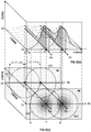
- Figure 3(a) illustrates the doses deposited as a function of time at a given point on a plane (Pk). It can be seen that at a time (t) of approximately 400 ms a first dose (Di) was deposited by a first beamlet at ultra-high dose rate (DRi) of over 1200 Gy / s, well within FLASH-RT effect. The same point, however received doses (D1, D2, Di+1, Dk) which "leaked” from adjacent beamlets at times of about 280 ms, 500 ms, and 600 ms at different dose rates (DR1, DR2, DRk).
- the present invention solves the problem of ensuring that a target treated by PBS of charged particles is effectively irradiated at HDR where required taking account of any overlapping dose deposition distribution of all beamlets leaking over a given spot to be treated.
- the present invention concerns a treatment planning system (TPS) for generating a plan for treatment by radiation with charged particles beams, preferably with proton beams, applied by pencil beam scanning (PBS) onto a target tissue.
- TPS treatment planning system
- the boundaries of the target tissue are defined within a peripheral surface which encloses tumoral cells, and which is surrounded by healthy cells and/or encloses also healthy cells.
- the healthy cells form healthy tissues.
- the treatment plan consists of N fractions of irradiation, with N ⁇ 1, and the treatment plan fulfils the following criteria,
- the TPS comprises a dose definition stage defining the doses to be deposited within the peripheral surface and in the direct surrounding thereof, required for fulfilling the criterion (C1).
- the TPS comprises a beam definition stage defining positions and dimensions of the beamlets of the PBS during the at least one high rate fraction, the beams definition stage comprising
- HDR ultra-high dose deposition rate
- the TPS differs from state of the art TPS' in that it also comprises a beamlets scanning sequence stage defining a scanning sequence of irradiation of the beamlets, the beamlets scanning sequence stage comprising an optimization of a time sequence of beamlets emission according to the spot positions pattern (x, y) defined in the beam definition stage such that at the end of a fraction j, a dose is deposited onto at least a predefined fraction, preferably of at least 50%, more preferably of at least 75%, of each specific volume at a mean deposition rate (DRa) superior or equal to a predefined value (DRa0) of a mean ultra-high dose deposition rate boundary (DRa ⁇ DRa0), in order to fulfil the requirements (C2.1) and (C2.2) defined supra.
- DRa mean deposition rate
- DRa ⁇ DRa0 mean ultra-high dose deposition rate boundary
- a medical practitioner can define a threshold dose value below which a healthy cell is not at risk (or at least at limited risk). It is preferred that the treatment plan favours those portions of each specific volume which receive a dose lower than or equal to the threshold dose value as the portions complementary to the predefined fraction into which a dose was not or could not be deposited at a value of DRa ⁇ DRa0. This way, for example, if a treatment plan manages,
- x 40% 90% of the cells in the specific volume could be spared, either by depositing high doses at HDR (i.e., DRa ⁇ DRa0), or by depositing low doses only, of limited impact on the cells health.
- the value of the threshold dose value depends on the organ being irradiated, and on the patient in general (age, gender, weight, etc.) and can be defined by a clinician or medical practioner.
- the beams definition stage comprises,
- the beam axes of two adjacent proton beamlets distributed according to the spot positions pattern (x, y) are separated from one another by a distance comprised between 1.2 and 2.5 times ⁇ , preferably 1.3 to 1.5 times ⁇ , wherein ⁇ 2 is the variance of a Gaussian dose distribution in the spots on the surface plane (P0) formed by the two adjacent proton beamlets.
- the specific volumes can be defined according to one or more of the following,
- each specific volume is comprised within a specific peripheral surface and the scanning sequence optimization for each specific volume is determined as follows
- each specific volume is comprised within a specific peripheral surface and the sequence optimization for each specific volume is determined as follows,
- each specific volume is comprised within a specific peripheral surface and the sequence optimization for each specific volume is determined as follows,
- the specific volume has a width larger than the width of the first scarf
- the scanning sequence optimization further includes defining a second and optionally a sequence of third and successive scarves, each parallel to the first scarf, and each adjacent to or slightly impinging with the preceding scarves in the sequence of first, second and successive scarves.
- the beam definition stage, the dose rate definition stage, and the beamlets scanning sequence stage are determined by a pre-optimizer module separate from, and interacting with a conventional TPS system determining the dose definition stage.
- K(E) wherein Imax is a maximum intensity (Imax) a nozzle of a proton accelerator can deliver, and K(E) is a known function relating the proton fluence to the incident energy of the proton beam.
- a single-beam treatment plan is first determined using a single beam composed of several beamlets parallel to a first beam direction.
- a multi-beam treatment plan is determined using two beams or more beams, each composed of several beamlets and each parallel to different beam directions, all secant to one another, until at least the predefined fraction of spots is irradiated at DRa > DRa0.
- the dose definition stage preferably includes the definition of an energy shaping device for defining beamlets having an optimized Sum of Bragg Peaks (SOBP) along the penetration depth (z) for each spot of the spot position pattern (x, y).
- SOBP Sum of Bragg Peaks
- the present invention concerns a treatment planning system for generating a plan for treating with one or more charged particle beams of a target tissue (3t) delivered by pencil beam scanning (PBS).
- target tissues are illustrated in Figures 1(b) , 4(a) , 4(c) , 5(a) , 5(c) , 6(a), and 6(b) comprising tumoral cells enclosed within a peripheral surface, which is surrounded by healthy cells and/or encloses also healthy cells, wherein the healthy cells form healthy tissues (3hi) wherein the subscript i designates the type of healthy tissues (3hi).
- the TPS generally comprises a computer or processor configured for generating the treatment plan, including for example, optimizing the nature and number of beams or beamlets required for fulfilling predefined criteria.
- the nature of the beam includes the type of charged particles, the intensity of the beam, the doses to be deposited, the dose deposition rates, the direction of the beams, the number and frequency of fractions, and the like.
- the charged particles are preferably protons.
- the charged particle beam or beams according to the present invention are delivered by pencil beam scanning (PBS).
- the plan consists of N fractions of irradiation, with N ⁇ 1, the TPS must optimize the nature and number of beam irradiations fulfilling the following criteria,
- the TPS comprises,
- each beamlet when irradiating a specific volume (Vs) with beamlets by PBS, although each beamlet can deposit doses at ultra-high dose deposition rate (HDR), because of the overlapping of the spots defining the dose distribution on planes normal to the beam direction (z), which increases the radiation time ( ⁇ t) of a given volume as shown in Figure 3(a) , to a point wherein the mean dose deposition rate (DRa) becomes lower than a predefined mean ultra-high dose deposition rate boundary (DRa ⁇ DRa0), required by the plan to ensure that the treatment plan fulfils a predefined NTCP value.
- HDR ultra-high dose deposition rate
- the TPS of the present invention further comprises a beamlets sequence stage defining a sequence of irradiation of the beamlets.
- the beamlets sequence stage comprises a sequence optimization of a time sequence of beamlets emission according to the spot positions pattern (x, y) defined in the beam definition stage such as to yield for at least a predefined fraction of the spots included in or intersecting each specific volume a mean dose deposition rate (DRa) which is superior or equal to a predefined value (DRa0) defining a mean ultra-high dose deposition rate boundary (DRa ⁇ DRa0 ⁇ 1 Gy / s), in order to fulfil the requirements (C2.1) and (C2.2) defined supra.
- DRa mean dose deposition rate
- the predefined fraction preferably is 50%,more preferably 75%, most preferably 90%, and optimally at least 95% or 98%
- the percentile is at least 95%, preferably at least 98% and can even be 100% depending on the specific cases, of the total sum of doses Dj.
- the exact value of the percentile between 95 and 100% can easily be defined by a skilled person depending on the situation (e.g., distribution and values of the doses deposited as a function of time as shown in Figure 3(a) ).
- the dose definition stage defines the doses to be deposited within the peripheral surface and in the direct surrounding thereof, required for killing the tumoural cells comprised within the peripheral surface and thus fulfilling the criterion (C1). This stage is well known to the person skilled in the art. This operation is also referred to as a definition of the spot weights.
- the dose definition stage assumes the use of an energy shaping device for defining beamlets having an optimized Sum of Bragg Peaks (SOBP) along the penetration depth (z) for each spot of the spot position pattern (x, y).
- SOBP Sum of Bragg Peaks
- the actual geometry of the energy shaping device is computed after the dose definition stage.
- the weight of the spots must be optimized before the shape of the energy shaping device can be computed in order to obtain the desired spot weights
- HDR ultra-high dose deposition rate
- the dose rate definition stage takes into account the performance of the particle treatment system available for carrying out the plan.
- DRmax a highest dose rate
- K(E) K(E)
- the dose rate definition stage can also define the maximum scanning speed, i.e. the maximum speed at which the spot can move from one location to another in a plane normal to the proton beam.
- the next stage is to define the characteristics of one or more beams required for implementing the chart. This stage is defined in the beam definition stage.
- the beam definition stage defines the type of charged particles to be irradiated (preferably protons), the number N of fractions j comprised by the treatment, and the positions and dimensions of the beamlets of one or more beams of the PBS during the at least one high rate fraction, This stage also defines the number of beams and beam directions (z, z1, z2), the superposition of coaxial beamlets to define the shape of the SOBP as a function of the geometry of the target tissue (3t) produced by each beamlet, the intensity of the beamlets, and the like.
- the beam definition stage comprises at least two steps,
- a spot (S01, S02) of diameter (d) is formed on a surface plane (P0) by a beamlet (B1, B2) propagating along a beamlet axis substantially parallel to a beam direction and intersecting substantially perpendicularly the surface plane (P0) at a spot centre (cp, cr), wherein the surface plane (P0) contacts the skin of the patient at least at the spot centre.
- the diameter of a spot depends on the dose distribution deposited on the surface plane (P0) by said beamlet.
- the dose distribution on the surface plane follows a substantially normal or Gaussian distribution, as illustrated in Figure 3(b) , centred on the intersection point (cp, cr) of the beamlet axis with the surface plane (P0) and of variance ⁇ 2 .
- a beamlet (B1, B2) deposits only a limited dose at the surface plane (P0) and deposits substantially the whole dose within a limited depth portion defined by the shape of the corresponding SOBP.
- shape of the dose distribution can be considered as remaining a gaussian all along the penetration depth (z) varying only on the value of the maximum dose deposited centred on the beamlet axis.
- the maximum dose as a function of the penetration depth (z) is defined by the corresponding SOBP.
- the diameter of each spot is approximately independent of the penetration depth (z) or, in other words, that each beamlet propagates along a cylinder.
- the spot diameter (d) is herein measured at the surface plane (P0) because this is a fixed plane independent of the location and geometry of the peripheral surface. It is clear that the same exercise can be performed on any plane along the penetration depth (z) of the beamlet. Since the two assumptions supra are correct at least as a first approximation, very similar results would be obtained independently of the penetration depth (z) the plane taken as reference intersects the central axis of the beamlet (B1, B2).
- Irradiation by pencil beam scanning requires a spot position pattern (x, y) to be defined on the surface plane (P0) of the spots (S01, S02) formed by different beamlets substantially parallel to the beam direction.
- the spots positions pattern (x, y) must ensure that the spots and corresponding beamlets cover an entirety of the target tissue (3t). This can be achieved by defining a surface target outline (T0) and a surface healthy outlines (H0i) formed by a projection onto the surface plane (P0), parallel to the beam direction, of the peripheral surface of the target tissue (3t), and peripheral surfaces of the healthy tissues (3hi) surrounding the target tissue (3t).
- the spot positions pattern (x, y) on the surface plane (P0) is determined to homogeneously cover an area enclosed within the surface target outline (T0).
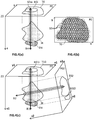
- An example of spot position pattern (x, y) is schematically illustrated in Figures 4(b) and 7 .
- a homogeneous covering of the area enclosed within the surface target outline (T0) can be obtained by separating from one another the beamlet axes of two adjacent proton beamlets distributed according to the spot positions pattern (x, y) by a distance comprised between 1.2 and 2.5 times ⁇ , preferably 1.3 to 1.5 times ⁇ , wherein ⁇ 2 is the variance of the Gaussian dose distribution in the spots on the surface plane (P0) formed by the two adjacent proton beamlets.
- the distances separating two adjacent spot axes needs not be constant for all pair of adjacent spots, and they can vary from one another to fit the geometry of the peripheral surface. Regular arrays of spots of equal diameter only are illustrated in the Figures for sake of simplicity. It is clear that the beam definition stage can define spots of different diameters and distributed according to any pattern or even randomly, as long as the whole volume of the target tissue (3t) is thus covered.
- such spot positions pattern on a line parallel to the axis (x) yields a wavy dose distribution pattern with maxima at the level of the beamlets axes, and with minima at mid-distance between two adjacent beamlet axes.
- the dose distribution pattern becomes more complex when the PBS scans a second series of spots parallel to the axis (x) and offset with respect to the beamlets (B1, B2) represented in Figure 3(b) , depending on whether the beamlets in the second line are aligned or staggered with respect to the beamlets of the first line. This depends on the spot positions pattern (x, y) defined by the TPS.
- the TPS of the present invention includes an additional stage designed for ensuring that DRa ⁇ DRa0 for at least a predefined fraction of each of the one or more specific volumes (Vs). This additional stage is referred to as beamlets scanning sequence stage.
- the gist of the present invention is the addition in the TPS of a beamlets-scanning sequence stage, which must ensure that the scanning sequence guarantees that a dose is deposited onto at least a predefined fraction, preferably of at least 50%, more preferably of at least 75%, of each specific volume (Vs) at a mean dose deposition rate (DRa) superior or equal to a predefined value (DRa0) of the mean ultra-high dose deposition rate boundary (DRa ⁇ DRa0 ⁇ 1 Gy/s), in order to fulfil the requirements (C2.1) and (C2.2) defined supra.
- the percentile is typically at least 95%, preferably at least 98% of the doses cumulative dose deposited.
- a percentile of the dose delivered during the fraction allows small doses deposited at one spot to be ignored, which cause limited damage to the healthy cells, but substantially increase the total irradiation time ( ⁇ t), artificially bringing DRa below DRa0, in cases where the FLASH effect would be present.
- ⁇ t total irradiation time
- the doses corresponding to the peaks DR1 and DRk are visibly very low compared with the doses corresponding to the peaks DR2, DRi, and DRi+1 (cf. dotted cumulative dose curve of Figure 3(a) ).
- a percentile ⁇ 100% e.g., 95% or 98% would exclude the small doses corresponding to peaks DR1 and DRk, thus reducing slightly the value of the numerator ( ⁇ Dj).
- the total time ( ⁇ t) at the denominator would thus be reduced substantially.
- DRa95 ⁇ Dj / ⁇ t for a percentile of 95% would therefore be substantially higher than DRa100 (i.e., DRa95 >> DRa100). Since the doses excluded from a percentile of 95% would account for only 5% of the total dose, it can safely by assumed that they have a limited damaging effect on the healthy cells compared with the other doses. Consequently, the FLASH effect is actually present with the deposition of the doses corresponding to the peaks (DR2, DRi, DRi+1), deposited within a shorter period ( ⁇ t).
- the specific volumes (Vs) is to be defined by a clinician. It must include healthy cells, which are to be irradiated at HDR to decrease the corresponding NTCP.
- the specific volume includes the whole target tissue (3t) defined within the peripheral surface and a safety layer surrounding part or all of the peripheral surface and containing healthy cells. Note that the peripheral surface may also enclose healthy cells too. This embodiment can be implemented for target tissues of small dimensions, because irradiating at HDR becomes difficult for a given particle therapy systems when the dimensions of the specific volume increase.
- Vs specific volumes
- the specific volumes (Vs) can be defined according to one or more of the following criteria.
- a first type of specific volume (Vs) is a volume containing cells located on either side of a portion of the peripheral surface most remote from the surface plane (P0) and crossed by the beams of the PBS to exit the target tissue (3t). This is the embodiment illustrated in Figures 4(a) and 4(c) , 5(a) to 5(e) , and 6(a) to 6(g) .
- This specific volume is particularly important in case the healthy tissue (3hi) is sensitive to radiations, and is in contact or directly adjacent to the peripheral surface, since the tumoural cells within the peripheral surface must be killed, and the healthy tissue (3hi) must be spared, with sometimes a few millimetres separating the tumoural cells from the healthy cells.
- a second type of specific volume (Vs) is called an uncertain zone (3z) and is defined as a zone comprising both tumoural and healthy cells intermixed at different ratios. Since it contains tumoural cells, the uncertain zone (3z) is at least partly located within the peripheral surface. The healthy and tumoural cells are intermixed, or the uncertain zone can also form small islands or clusters of healthy cells within the peripheral surface. This kind of volume is also very critical, since there is no clear boundary separating tumoural cells from healthy cells. To date, the healthy cells contained in an uncertain zone (3z) are generally sacrificed to ensure the killing of the tumoural cells mixed therewith.
- a third type of specific volume is a volume containing healthy cells of a healthy tissue (3hi) which are intersected by one or more beamlets of diameter (d). These healthy cells can be more remote from the peripheral surface, but due to several beams or beamlets crossing such volume, the healthy cells can be dangerously exposed to radiations.
- the beamlets scanning sequence stage comprises the following steps,
- Selection of the beam scanning sequence yielding DRa ⁇ DRa0 for at least the predefined fraction of each selected volume (Vs) can be achieved by different methods. Initial steps required prior to implementing any of the following methods include,
- a first method for selecting a beam scanning sequence yielding DRa ⁇ DRa0 for at least the predefined fraction of each selected volume (Vs) is the local optimization method.
- the present method optimizes each step sequentially, aiming at maintaining as high a value of DRa as possible at each sequential step.
- each specific volume (Vs) is comprised within a specific peripheral surface and the sequence optimization for each specific volume (Vs) is initiated with the following steps,
- a dose is delivered to a first spot centre (cp) of the sub-set which is crossed by a first beamlet (B1) and the doses delivered by the first beamlet to neighbouring spot centres (cr) are recorded.
- the first spot is preferably located adjacent to the specific volume outline (V0), more preferably at a corner of the outline (V0). If the first spot is not adjacent to or at a corner of the outline (V0), the algorithm will choose a sequence that leads the following spots towards the outline or towards a corner thereof, if any.
- a second spot centre (cr) of the sub-set is selected to be irradiated directly after the first spot centre (cp), such as to fulfil one or more of the following constraints,
- the local optimization method is quite straightforward and easy to implement, requiring moderate to low computational power.
- each specific volume (Vs) is comprised within a specific peripheral surface and the sequence optimization for each specific volume (Vs) is initiated with the following steps,
- an initial sequence ranking is assigned in the beam scanning sequence.
- a value is defined for a maximum ranking jump (h) a spot centre can make in one permutation ⁇ (p), i.e.
- the total permutation is composed of M such ⁇ (p) permutations applied sequentially to the initial sequence.
- a weighted neighbour ranking distance of a spot centre (cp, cr) at a starting sequence ranking (p) is defined as follows,
- Ultra-high dose rate (HDR) irradiation can be performed on small fields by PBS using particle therapy systems currently available on the market.
- This performance can be taken advantage of in yet an alternative method for selecting a beam scanning sequence yielding DRa ⁇ DRa0 for at least the predefined fraction of each selected volume (Vs), referred to as the scarf method.
- each specific volume (Vs) is comprised within a specific peripheral surface and the sequence optimization for each specific volume (Vs) is initiated with the following steps,
- a scarf sequence unit cell is defined with the following steps, illustrated in Figure 7 ,
- the width (W) of the scarf is limited by the constraint that the mean dose deposition rate (DRa) of the 2w th spot, which is adjacent to the first spot, is superior or equal to the predefined value (DRa0) (i.e., DRa(S0v(2w)) ⁇ DRa0).
- the scanning sequence optimization can further include defining a second and optionally a sequence of third and successive scarves, each parallel to the first scarf, and each adjacent to or slightly impinging with the preceding scarves in the sequence of first, second and successive scarves, as illustrated in Figure 7 .
- This method is advantageous in that it can cover an area of substantially unlimited length (L), as discussed supra, but also of substantially unlimited width (W).
- the stripe encloses healthy cells, and the deposited doses are high enough to kill the cells, this stripe must be considered as sacrificial.
- a clinician must decide whether a sacrificial stripe is agreeable and may decide to locate it such as to affect the least possible healthy cells.
- the scarf needs not be in the shape of a rectangle as illustrated in Figure 7 in case the spot position pattern (x, y) is not aligned along two straight directions normal to one another.
- the clinician may use a different method for selecting a beam scanning sequence yielding DRa ⁇ DRa0 for at least the predefined fraction of each selected volume (Vs).
- the scarf method can be implemented to other patterns than scarves, such as a spiral pattern.
- the TPS described supra include a single beam composed of several beamlets parallel to a first beam direction.
- a multi-beam treatment plan can be implemented instead.
- a multi-beam treatment plan uses two or more beams, each composed of several beamlets and each parallel to different beam directions (z1, z2), all secant to one another.
- the beamlets scanning sequence stage is repeated with additional beams until at least the predefined fraction of spots is irradiated at DRa ⁇ DRa0.
- using more than one beam allows a larger dose to be deposited into the target (3t) where two beams cross each other.
- the dose rate constraints (DRa ⁇ DRa0) are considered for each beam independently. Using several beams extends the duration of a treatment fraction j. Again, this is a choice to be made by the clinician.
- the TPS of the present invention can be implemented to existing "conventional TPS" by including a pre-optimizer module separate from and interacting with the conventional TPS.
- the pre-optimizer module may be configured for determining the beamlets scanning sequence stage only. In a preferred embodiment, however, the beam definition stage, the dose rate definition stage, and the beamlets scanning sequence stage are determined by the pre-optimizer module.
- the pre-optimizer module takes into account the performance of the particle therapy system used for later implementing the TPS to establish for a given spot position pattern (x, y) determined by the beam definition stage, the number, dimensions, and geometries of the selected volumes (Vs) defined by the beamlets scanning sequence stage, which can reasonably be irradiated at HDR by the particle therapy system with the dose rates defined by the dose rate definition stage, ensuring that DRa ⁇ DRa0 at least in the predefined fraction of Vs.
- the pre-optimized module Once the pre-optimized module has established that it is possible with a given particle therapy system to irradiate the specific volumes (Vs) such that DRa ⁇ DRa0 in at least the predefined fraction of Vs, the parameters determined by the pre-optimized module can be introduced into the conventional TPS for establishing and defining the dose definition stage. This is very advantageous when using existing particle therapy systems and existing conventional TPS, which were not designed to implement the properties of the FLASH effect.
- the pre-optimized module allows setting the bases for a realistically implementable TPS with irradiation of the predefined fraction of Vs at HDR (i.e., DRa ⁇ DRa0), which last and certainly not least step of defining the doses to be deposited within the target tissue (3t) is to be defined by the dose definition stage carried out by the conventional TPS.
- the definition of the treatment plan can be an iterative process, wherein the results of a former run are used as starting parameters for a next run, until an agreeable treatment plan is obtained.
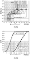
- Figure 2(a) shows iso-NTCP lines in a plot of the dose deposition rate (DR) as a function of healthy dose (Dhij) for values of NTPC comprised between 10% and 100% probability.
- DR dose deposition rate
- Dhij healthy dose
- the equivalent healthy fraction dose (Dmhij) is an equivalent dose applied at least partly at HDR and yielding a same or lower probability of complication of a healthy cell (3hi) (NTCP01) as if the healthy fraction dose (Dhij) had been deposited onto the healthy cell at a conventional dose deposition rate (CDR) only.
- the healthy cells must be spared by fulfilling the criteria (C2.1) and (C2.2), defined supra and reproduced below,
- the value of the equivalence coefficient ⁇ can be determined for dose depositions at ultra-high dose deposition rates (HDR) by establishing NTCP curves as a function of dose (Dhij) and dose deposition rate (DR) as illustrated for example in Figures 2(a) and 2(b) .
- Figure 2(c) illustrates various examples of the relationship between the equivalent healthy fraction dose (Dmhij) and the healthy fraction dose (Dhij).
- Dmhij Dchij + ⁇ Dhhij
- Dhij Dchij + Dhhij
- the mean ultra-high dose deposition rate boundary (DRa0) to be reached for sparing healthy cells present in specific volumes (Vs) by FLASH effect can be determined using the equivalent healthy fraction dose (Dmhij) described supra.
- Dmhij equivalent healthy fraction dose
- NTCP0i the predefined probability of complication
- the minimum value of the mean ultra-high dose deposition rate boundary (DRa0) required for depositing a given dose within the predefined value of NTCP0i by reading the value of the dose deposition rate (DR) on the ordinate of Figure 2(a) , corresponding to the intersection point between the NTCP0i curve and the value of the given dose in the abscissa of Figure 2(a) .
- DRa0 mean ultra-high dose deposition rate boundary
- the TPS of the present invention takes for the first time in consideration the mean dose deposition rate (DRa) as a determining parameter for obtaining or not a FLASH effect. It also takes into consideration the performance of the particle therapy system used for the treatment. This issue arises with irradiation of a target by PBS, which involves sequentially depositing doses to a specific sub-volume, then to a second specific volume, and so on until the whole volume of the target is irradiated.
- PBS can be a discrete PBS, wherein a beamlet irradiates the target tissue along a trajectory centred on a first spot.
- the beamlet is interrupted for the time required for moving the beamlet from the first spot in the sequence to the second spot in the sequence, and thence the beamlet is activated again to irradiate the target tissue along a trajectory centred on the second spot.
- the PBS can be a continuous PBS, wherein the beamlet is not interrupted during the translation from a first spot to a second spot in the sequence.
- the scarf method is suitable for implementing both discrete and continuous PBS.
- DRa mean dose deposition rate
- the TPS of the present invention ensures that at least a predefined fraction of the specific volumes (Vs) be irradiated by PBS at a mean dose deposition rate, DRa ⁇ DRa0. This way, the FLASH effect can be effectively used to spare a substantial number of healthy cells, whilst killing the tumoural cells contained within the peripheral surface.
Landscapes
- Health & Medical Sciences (AREA)
- Engineering & Computer Science (AREA)
- Biomedical Technology (AREA)
- Pathology (AREA)
- Nuclear Medicine, Radiotherapy & Molecular Imaging (AREA)
- Radiology & Medical Imaging (AREA)
- Life Sciences & Earth Sciences (AREA)
- Animal Behavior & Ethology (AREA)
- General Health & Medical Sciences (AREA)
- Public Health (AREA)
- Veterinary Medicine (AREA)
- Radiation-Therapy Devices (AREA)
Abstract
• a dose definition stage defining the doses to be deposited within the peripheral surface
• a beam definition stage defining positions and dimensions of the beamlets of the PBS during the at least one high rate fraction, the beams definition stage comprising
• a dose rate definition stage comprising at least one high rate fraction j, wherein specific volumes (Vs) comprising healthy cells are irradiated at a ultra-high dose deposition rate (HDR), wherein HDR = Dj / t ≥ 1 Gy / s, j, and
• a beamlets scanning sequence stage defining a scanning sequence of irradiation of the beamlets.
Description
- The present invention relates to a treatment planning system (TPS) for generating a plan for treatment with charged particles beams, preferably with proton beams, by pencil beam scanning (PBS) of a target tissue comprising tumoural cells. The plan fulfils predefined clinical criteria for ensuring that at the end of the treatment, the tumoural cells are destroyed or killed, whilst preserving the healthy cells adjacent to the tumoural cells. The TPS establishes the plan over N irradiation fractions including doses deposited at ultra-high dose deposition rates (HDR) into specific volumes (Vs). The TPS optimizes the scanning sequence of the PBS to ensure that, taking account of the performance of the treatment equipment, doses are deposited at a mean dose deposition rate (DRa) superior or equal to a predefined value (DRa0) of a mean ultra-high dose deposition rate boundary (DRa ≥ DRa0), into at least a predefined fraction of the volume of each specific volume (Vs).
- The plan thus generated ensures an effective treatment of the tumoural cells, with a lower ratio of damages to healthy cells adjacent to the tumoural cells tailored to the particle treatment system used for implementing the treatment plan.
- Radiation therapy with particles or waves, such as electron beams, protons beams, heavy ions beams, x-rays, γ-rays, and the like, has become an essential tool for treating patients with tumours.
- Pencil beam scanning (PBS) is a technique consisting of steering a beam of charged particles towards a target comprising tumoral cells. PBS reduces unnecessary radiation exposure to surrounding non-cancerous cells by shaping the area being treated to mirror the tumour geometry. Beside the geometry of the target, PBS allows local tuning of the intensity of a beamlets depending of the position of the irradiated cells within the target.
- Pencil beam scanning can treat a tumour with a single beam composed of various beamlets or with multiple beams of different orientations each composed of various beamlets, sometimes called intensity modulated proton therapy (IMPT).
- Since both tumoural cells and healthy cells are damaged by such radiations, a major challenge in cancer treatment is to define a plan ensuring that the tumoural cells are effectively destroyed or killed, while sparing as much as possible the healthy cells, in particular those adjacent to the tumoural cells. A first step of a treatment plan is the capture of images of the tumoural region by CT-scan. Based on these images, an oncologist identifies the right targets and determines the locations and doses to be deposited to kill the tumoural cells. Such plan must satisfy multiple, often competing, parameters, and is therefore quite complex. For this reason, treatment planning systems are generally computer generated.
- A first criterion a treatment plan must fulfil is to ensure that, at the end of the treatment, a total target dose (DmtT) greater than or equal to a minimum target dose (DmtTO) has been delivered to the tumoural cells forming the target effective for destroying / killing the tumoural cells.
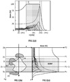
- A second criterion to be fulfilled by the treatment plan is to minimize the degradation of the healthy cells adjacent to the tumoural cells. No matter how accurate is the dose deposition, even by PBS, in a volume comprising tumoural cells, a radiation beam reaching the volume comprising the tumoural cells almost necessarily crosses healthy cells and delivers thereto a dose also to healthy cells surrounding or included in that volume. Different radiations deposit their energies in different patterns. For example, X-rays deposit most of their energy near the level of the skin, and the deposited energy decreases with depth. Healthy tissues located upstream of a target volume of tumoural cells therefore receive a higher dose than the tumoural cells of target volume. By contrast, as shown in
Figures 1(a) &1 (c), charged particle beams, in particular protons deposit most of their energy close to the end of their beam path, forming a so-called Bragg peak. By superposing a number of beamlets with their respective Bragg peaks staggered in depth, a sum of individual Bragg Peaks (SOBP) can be defined spanning a whole depth of the volume of tumoural cells or of a fraction of that volume. The healthy cells located upstream of the volume of tumoural cells crossed by a proton beam therefore receive a lower dose than the tumoural cells in the volume. Consequently, proton therapy is well suited for depositing high doses in deep seated tumours. - To minimize the degradation of the healthy cells adjacent to the tumoural cells, the total dose (DhTi) received by a healthy cell must not exceed a maximum allowable dose. As the maximum allowable dose a healthy cell can (relatively) safely receive in one session may be substantially lower than the minimum target dose (DmtTO) required to destroy the tumoural cells, the total target dose (DmtT) is often delivered to the tumoural cells in one or more fractions (or sessions).
- A treatment plan can therefore include the delivery of a predefined total target dose (DmtT) of radiation to all the tumoural cells in N sessions or fractions j, with N ≥ 1, each fraction j delivering a target fraction dose (Dmtj) to a volume of tumoral cells. If N = 1, the whole of the predefined total target dose is delivered in a single session. If N > 1, the predefined total target dose is delivered in several fractions, possibly to different volumes of tumoral cells, such that at the end of the Nth session, all the tumoral cells have received a cumulated target dose equal to the predefined total target dose (DmtT) required for killing all the tumoural cells. The number N of fractions depends on the nature of the healthy tissues which determines the maximum fraction dose they can safely receive in a fraction. It also depends on the type of radiation used and on the positions of the healthy cells relative to the tumoral cells, as these parameters at least partially determine the dose deposited on healthy cells crossed by a radiation beam aiming at depositing a target fraction dose (Dmtj) onto a volume containing tumoural cells.
- It has been observed that the tumoural cells have a longer recovery time to recover from the damages suffered after an irradiation fraction than healthy cells. This allows a treatment plan to span over several fractions distributed over a period of several days and weeks. By ensuring that
- (a) the healthy cells receive fraction doses low enough to preserve them,
- (b) The tumoural cells receive a total target dose cumulated over the N fractions at least equal to the minimum target dose (DmtT), and
- (c) A recovery time between two successive fractions is sufficient to allow substantial recovery of the healthy cells, but not of the tumoural cells,
- The treatment plan can ensure that at the end of the treatment, all the tumoural cells have been destroyed, while sparing most healthy cells.
- Maximum fraction dose and maximum total dose acceptable to the healthy cells can be defined relative to a Normal Tissue Complication Probability (NTCP) which defines the probability of a given tissue of developing complications upon exposure to a given radiation. Values of boundary doses of radiation yielding a given value of the NTCP for a selection of organs are available in the literature. For example, Kehwar, J. Cancer Res. Ther., Sept.2005, 1(3), 168, lists in Table 3, on p.171, a number of doses yielding a 50% NTCP of developing five years after the treatment symptoms as defined in the last column for a number of organs. The
volumes 1/3-3/3 in Table 3 indicate the portion of the total volume of the corresponding organ being irradiated. Alternatively, a medical practitioner can have other sources for determining boundary doses, such as personal experience, or referring to other experimental data. - Historically, treatment plans by radiation therapy included the delivery of radiation doses to the treated cells at a conventional dose deposition rate (CDR) lower than 1 Gy / s. With rare exceptions, current radiation therapy facilities deliver dose-rates around 0.1 Gy/s and most clinical protocols involve delivery at regular intervals of N target fraction doses (Dmtj) of 2 to 15 Gy cumulated to reach the total target dose (DmtT) which often exceeds the tolerance limit of normal tissues located in the radiation field, thus damaging them together with the tumoural cells. Recently and as illustrated in
Figures 2(a) and 2(b) , it has been observed that a same dose (D) had different effects on healthy cells but not on tumoral cells when deposited at conventional dose deposition rates (CDR) or at ultra-high dose deposition rate (HDR). HDR can be one or more orders of magnitude larger than conventional dose deposition rates (CDR) usually applied. Deposition of a dose at ultra-high dose deposition rates (HDR) is also referred to as FLASH-radiotherapy (= FLASH-RT). It has been observed experimentally on animals and on various organs, that ultra-high rate dose deposition at HDR can significantly spare healthy tissues in comparison with conventional deposition of a same dose at CDR and, at the same time, tumoural cells respond the same or even better to HDR deposition than to CDR deposition. For example, FLASH-RT reportedly elicits in mice a dramatic decrease of the incidence of lung fibrosis, of memory loss subsequent to brain irradiation, and of necrosis of the small intestine whilst keeping the anti-tumour efficiency unchanged. Such specific normal tissue sparing has been confirmed in large animals and a patient with cutaneous lymphoma has already been treated with FLASH-RT. - As illustrated in
Figures 3(b) and 3(c) , a single beamlet propagating along a beam direction (z) radially deposits doses approximately according to a Gaussian distribution curve, normal to the beam direction (z).lnFigure 3(b) , Gaussian deposition curves are illustrated along a direction (x) normal to the beam direction (z).Figure 3(c) illustrates with shade codes the dose distribution deposited radially by a beamlet. As can be seen inFigures 3(b) and 3(c) , the beam axes of two adjacent proton beamlets in PBS are distributed according to a spot positions pattern (x, y) and are generally separated from one another by a distance comprised between 1.2 and 2.5 times s, preferably 1.3 to 1.5, wherein s2 is the variance of the Gaussian dose distribution in the spots on the surface plane (Pk) normal to the beam direction (z). It follows that a beamlet (B1) deposits a dose onto an area of the plane (Pk) which impinges over the zone of dose deposition by a second beamlet (B2) adjacent to the first beamlet (B1), yielding the wavy distribution curve illustrated inFigure 3(b) (two lumps only are illustrated, but this shape becomes more complex with additional adjacent beamlets propagating along the beam direction (z) at a different y-position from the first and second beamlets (B1, B2). Such overlap is essential to ensure a uniform dose deposition of a whole area on the plane (Pk). This has, however, an unexpected effect on the FLASH effect, illustrated inFigure 3(a) . The amplitude of the wavy distribution curve depends inter alia on the distance between two adjacent spots and on the number of spots delivering a dose at a given location. -
Figure 3(a) illustrates the doses deposited as a function of time at a given point on a plane (Pk). It can be seen that at a time (t) of approximately 400 ms a first dose (Di) was deposited by a first beamlet at ultra-high dose rate (DRi) of over 1200 Gy / s, well within FLASH-RT effect. The same point, however received doses (D1, D2, Di+1, Dk) which "leaked" from adjacent beamlets at times of about 280 ms, 500 ms, and 600 ms at different dose rates (DR1, DR2, DRk). Although the doses of each beamlet were deposited at an ultra-high dose rate greater than 1 Gy/s, the overall irradiation time (Dt) of said point is such that a mean dose deposition rate, DRa = S Dj / Dt can be lower than 1 Gy/s, thus losing the FLASH-RT effect. There is a danger in case the cumulated dose (S Dj) (of approximately 22 Gy according to the dotted line inFigure 3(a) ) is adequate when the FLASH-RT effect is present, but not at CDR. Since all individual doses were deposited at ultra-high dose deposition rate (HDR), the clinician may be of the impression that FLASH-RT effect was present thus sparing the healthy tissues. This impression, however, may be wrong in case the total dose was deposited over a period of time (Dt) such that at the mean deposition rate DRa < 1 Gy / s, the cumulated dose was deposited at CDR instead of HDR, thus exceeding the dose admitted by the required NTCP at CDR. - The present invention solves the problem of ensuring that a target treated by PBS of charged particles is effectively irradiated at HDR where required taking account of any overlapping dose deposition distribution of all beamlets leaking over a given spot to be treated. These and other advantages are described in more detail in continuation.
- The present invention concerns a treatment planning system (TPS) for generating a plan for treatment by radiation with charged particles beams, preferably with proton beams, applied by pencil beam scanning (PBS) onto a target tissue. The boundaries of the target tissue are defined within a peripheral surface which encloses tumoral cells, and which is surrounded by healthy cells and/or encloses also healthy cells. The healthy cells form healthy tissues. The treatment plan consists of N fractions of irradiation, with N ≥ 1, and the treatment plan fulfils the following criteria,
- (C1) at the end of the N fractions, all tumoral cells of the target tissue (3t) must have received a total target dose (DmtT) equal to the sum of target fraction doses (Dmtj) received at each fraction (i.e., DmtT = ∑ Dmtj), which is at least equal to a minimum target dose (DmtTO) for killing the tumoral cells, i.e., DmtT = ∑ Dmtj ≥ DmtTO,
- (C2) at the end of the N fractions, all healthy cells (3hi) of the healthy tissues surrounding or enclosed within the peripheral surface must have received a total healthy dose (DhTi) equal to the sum of the healthy fraction doses (Dhij) received at each fraction j (i.e., DhTi = ∑ Dhij), such that,
- (C2.1) the healthy fraction dose (Dhij) received at each fraction j does not exceed a predefined fraction dose threshold for preserving the healthy cells at the end of the fraction j, and
- (C2.2) the total healthy doses (DhTi) received and cumulated at the end of the N fractions does not exceed a predefined total dose threshold for preserving the healthy cells at the end of the treatment of N fractions.
- The TPS comprises a dose definition stage defining the doses to be deposited within the peripheral surface and in the direct surrounding thereof, required for fulfilling the criterion (C1).
- The TPS comprises a beam definition stage defining positions and dimensions of the beamlets of the PBS during the at least one high rate fraction, the beams definition stage comprising
- a definition of a diameter of a spot formed on a surface plane by a beamlet propagating along a beamlet axis substantially parallel to a beam direction and intersecting substantially perpendicularly the surface plane at a spot centre, wherein the surface plane contacts the skin of the patient at least at the spot centre,
- a definition of a spot position pattern (x, y) on the surface plane of the spots formed by different beamlets substantially parallel to the beam direction such that the spots positions pattern (x, y) ensures that the spots cover a whole area defined within a projection parallel to the beam direction of the peripheral surface onto the surface plane.
- The TPS also comprises a dose rate definition stage comprising at least one high rate fraction j, wherein specific volumes (Vs) bounded by a specific volume surface enclosing healthy cells and optionally tumoral cells are irradiated at a ultra-high dose deposition rate (HDR), defined as a dose deposition rate, HDR = Dj / t ≥ 1 Gy / s, wherein Dj is a dose deposited during one fraction onto a specific volume and t is the time of deposition of the dose Dj.
- The TPS differs from state of the art TPS' in that it also comprises a beamlets scanning sequence stage defining a scanning sequence of irradiation of the beamlets, the beamlets scanning sequence stage comprising an optimization of a time sequence of beamlets emission according to the spot positions pattern (x, y) defined in the beam definition stage such that at the end of a fraction j, a dose is deposited onto at least a predefined fraction, preferably of at least 50%, more preferably of at least 75%, of each specific volume at a mean deposition rate (DRa) superior or equal to a predefined value (DRa0) of a mean ultra-high dose deposition rate boundary (DRa ≥ DRa0), in order to fulfil the requirements (C2.1) and (C2.2) defined supra. A medical practitioner can define a threshold dose value below which a healthy cell is not at risk (or at least at limited risk). It is preferred that the treatment plan favours those portions of each specific volume which receive a dose lower than or equal to the threshold dose value as the portions complementary to the predefined fraction into which a dose was not or could not be deposited at a value of DRa ≥ DRa0. This way, for example, if a treatment plan manages,
- to deposit at DRa ≥ DRa0 doses higher than the threshold dose value over 60% of a specific volume, and at the same time,
- to deposit doses lower than the threshold dose value in 75% of the complementary 40% of the specific volume wherein doses were deposited at DRa < DRa0.
- It follows that 60% + 75% x 40% = 90% of the cells in the specific volume could be spared, either by depositing high doses at HDR (i.e., DRa ≥ DRa0), or by depositing low doses only, of limited impact on the cells health. The value of the threshold dose value depends on the organ being irradiated, and on the patient in general (age, gender, weight, etc.) and can be defined by a clinician or medical practioner.
- The mean deposition rate DRa is defined as, DRa = ∑Dj / Δt ≥ DRa0 ≥ 1 Gy / s, wherein ∑Dj is a sum of a percentile of all the doses deposited by one or more beamlets onto a given volume, wherein the percentile is at least 95%, preferably at least 98%, and Δt is the time between the first and last doses deposited onto the given volume.
- In one embodiment, the beams definition stage comprises,
- A definition of a surface target outline and of surface healthy outlines formed by a projection onto the surface plane, parallel to the beam direction, of the peripheral surface of the target tissue, and peripheral surfaces of the healthy tissues surrounding the target tissue,
- the spot diameter and spot positions pattern (x, y) on the surface plane are determined to homogeneously cover an area enclosed within the surface target outline,
- In this embodiment, it is preferred that the beam axes of two adjacent proton beamlets distributed according to the spot positions pattern (x, y) are separated from one another by a distance comprised between 1.2 and 2.5 times σ, preferably 1.3 to 1.5 times σ, wherein σ2 is the variance of a Gaussian dose distribution in the spots on the surface plane (P0) formed by the two adjacent proton beamlets.
- In this embodiment it is preferred that a first specific volume extends along a distance Vz = (Zn - Z1) measured along the beam direction (z) from the surface plane and wherein the beamlets scanning sequence stage comprises the following steps,
- a definition of n inner planes parallel to the surface plane and distributed at corresponding depths (Z1,..., Zn), between the depth Z1 at the level of the inner plane, and the depth (Zn) at a level of the nth inner plane such that the specific volume is sandwiched between the first and nth planes,
- a definition of a specific volume projection outlines formed by a projection onto the respective surface planes, parallel to the beam direction, of the corresponding specific volume surface, and
- a selection of the beam scanning sequence yielding for at least the predefined fraction of preferably at least 50%, more preferably at least 75% of a selected volume defined within a cylinder of base formed by the specific volume projection outline (V0) and of height Vz = (Zn - Z1), a mean dose deposition rate DRa ≥ DRa0, and
- According to the present invention, the specific volumes can be defined according to one or more of the following,
- at least one specific volume contains cells located on either side of a portion of the peripheral surface most remote from the surface plane (P0) and crossed by the beams of the PBS to exit the target tissue,
- at least one specific volume referred to as an uncertain zone is defined as a zone comprising both tumoural and healthy cells intermixed at different ratios,
- at least one specific volume contains healthy cells of a healthy tissue (3hi) which are intersected by one or more beamlets of diameter.
- In an embodiment of the invention, each specific volume is comprised within a specific peripheral surface and the scanning sequence optimization for each specific volume is determined as follows
- define a specific volume outline formed by a projection parallel to the beam direction of the specific peripheral surface of the specific volume onto the surface plane,
- define a sub-set of the spot position pattern (x, y) comprising the spots intersecting or included within the specific volume outline,
- deliver a dose to a first spot centre crossed by a first beamlet,
- record the doses delivered by the first beamlet to neighbouring spot centres,
- select a second spot centre to be irradiated directly after the first spot centre, such as to fulfil one or more of the following constraints,
- ∘ minimize ∑m (DRa(m) - DRT(m))2, wherein DRT(m) is a target average dose rate for each spot (m), and / or
- ∘ maximize an average of the average dose rates (DRa(m)) over all the spots measured, and / or
- ∘ maximize the average dose rates (DRa(m)) of each spot (m),
- repeat the foregoing steps with a third and following spots for all the spots of the sub-set of the spots position pattern (x, y).
- In an alternative embodiment, each specific volume is comprised within a specific peripheral surface and the sequence optimization for each specific volume is determined as follows,
- define a specific volume outline formed by a projection parallel to the beam direction onto the surface plane,
- define a sub-set of the spot position pattern (x, y) intersecting or included within the specific volume outline,
- for each position of the spot centres of the sub-set, assign an initial sequence ranking in the beam scanning sequence,
- define a value for a maximum ranking jump (h) a spot centre can make in one permutation π(p), i.e. |p - q| ≤ h
- define a first total permutation (u = 1) of the initial sequence ranking of the spot centres composed of M local permutations π(p) = q where p is an initial ranking of a given spot centre in the initial sequence ranking and q a final ranking after the permutation, with a condition of maximum ranking jump (h), wherein the total permutation is composed of M such π(p) permutations applied sequentially to the initial sequence,
- define a weighted neighbour ranking distance of a spot centre at a starting sequence ranking (p) as follows,
- ∘ define a weighted neighbour ranking distance (Dw(p, r)) between the spot centre (cp) at the initial sequence ranking (p) and a spot centre (cr) at a neighbouring sequence ranking (r), as Dw(p, r) = |p - r|·Ir,p(r), where |p - r| is a ranking difference (D(p, r)) between ranking sequences (p) and (r), and where Ir,p(r) is a dose (D) deposited onto the spot at position (cp) by a beam intersecting the position (cr),
- ∘ define a total weighted neighbour distance (Dt(p)) from the spot centre (cp) at the initial sequence ranking (p) to all spot centres at neighbouring ranks thereof, as Dt(p) = ∑ r Dw(p, r),
- calculate a cost (C,1(p, r)) of a local permutations π(p) = q as, C,1(p, r) = Dt(q) - Dt(p),
- calculate a first total cost Ct,1 (π) = ∑ p C,1(p,r), of the first total permutation (u = 1),
- define all possible second, third and successive total permutations (u = 2, 3, 4,...) of the initial sequence ranking for the chosen ranking jump (h), which are different from each other and from the first total permutation (u = 1),
- for each of the second, third; and successive total permutations defined in the preceding step, calculate a corresponding second, third, and successive total costs, Ct,u(π) = ∑ p C, u(p, r),
- select the total permutation (u = 1, 2, 3, ...) yielding the lowest total cost (Ct,u(π)).
- In yet an alternative embodiment, each specific volume is comprised within a specific peripheral surface and the sequence optimization for each specific volume is determined as follows,
- define a specific volume outline (V0) formed by a projection parallel to the beam direction of the specific peripheral surface of the specific volume onto the surface plane (P0),
- define a sub-set of the spot position pattern (x, y) comprising the spots intersecting or included within the specific volume outline,
- define a scarf sequence unit cell with the following steps,
- ∘ define an initial spot for being irradiated first by a first beamlet,
- ∘ define successive second, third, to wth spots, each sequentially adjacent to one another and all aligned along a width direction,
- ∘ define a (w + 1)th spot as being adjacent to the wth spot along a length direction, different from, preferably normal to the width direction,
- ∘ define (w + 2)nd to 2wth spots each sequentially adjacent to one another and all aligned along the width direction,
- ∘ define a (2w + 1)th spot as being adjacent to the 2wth spot along the length direction,
- repeat N times the steps for defining the scarf sequence unit cell, from an (Aw + 1)th spot (S0v(Aw + 1)) until a ((A + 2)w + 1)th spot (S0v((A + 2)w + 1), with A = 2 to (N + 2), forming a first scarf of width (W) equal to a distance separating the first from the wth spots, and of length (L) equal to the distance separating the first from the ((N + 4) w + 1)th spot, and wherein the width (W) of the scarf is limited by the constraint that the mean dose deposition rate (DRa) of the 2wth spot is superior or equal to the predefined value (DRa0).
- It is preferred in the last embodiment, that the specific volume has a width larger than the width of the first scarf, and that the scanning sequence optimization further includes defining a second and optionally a sequence of third and successive scarves, each parallel to the first scarf, and each adjacent to or slightly impinging with the preceding scarves in the sequence of first, second and successive scarves.
- In a preferred embodiment of the present invention, the beam definition stage, the dose rate definition stage, and the beamlets scanning sequence stage are determined by a pre-optimizer module separate from, and interacting with a conventional TPS system determining the dose definition stage.
- the dose rate definition stage defines a highest dose rate (DRmax) at which a given dose (Di) can be delivered by a beamlet, as, DRmax = 8 Imax . K(E), wherein Imax is a maximum intensity (Imax) a nozzle of a proton accelerator can deliver, and K(E) is a known function relating the proton fluence to the incident energy of the proton beam.
- According to the present invention, a single-beam treatment plan is first determined using a single beam composed of several beamlets parallel to a first beam direction. In case less than the predefined fraction of the specific volume is irradiated with a mean dose deposition rate (DRa) superior or equal to the predefined value (DRa0), a multi-beam treatment plan is determined using two beams or more beams, each composed of several beamlets and each parallel to different beam directions, all secant to one another, until at least the predefined fraction of spots is irradiated at DRa > DRa0.
- The dose definition stage preferably includes the definition of an energy shaping device for defining beamlets having an optimized Sum of Bragg Peaks (SOBP) along the penetration depth (z) for each spot of the spot position pattern (x, y).
- On these figures,
-
Fig. 1(a) shows the energy deposition onto tissues as a function of depth (z) of penetration for proton beamlets, adding up to form a sum of individual Bragg Peaks (SOBP) spanning over the whole depth of the tumour (3), -
Fig. 1(b) shows a cut parallel to a proton beam direction crossing a target tissue comprising tumoral cells, and -
Fig. 1(c) shows the corresponding SOBP. -
Fig. 2(a) shows iso-NTCP-lines as a function of dose (D) deposited into a healthy tissue and of the dose deposition rate (DR), -
Fig. 2(b) plots NTCP as a function of dose (D) deposited into a healthy tissue at CDR (white circles) and at HDR (black circles). -
Fig. 2(c) shows the relationship of Dmhij as a function of Dhij for different values of the equivalence coefficient (α). -
Fig. 3(a) shows the effect on overlapping dose distribution spots on the mean dose deposition rate (DRa). -
Fig. 3(b) shows the doses deposited over a plane (x, z) by two proton beamlets (B1, B2), with overlapping gaussian dose distribution curves along the axis (x), -
Fig. 3(c) shows a 3D view (x, y, z) of the approximately cylindrical propagation of the two beams (B1, B2) along the beam direction (z), the shades of grey illustrating the doses deposited on a plane (Pk) located at a depth (Zk) from the surface of the skin of a patient, and -
Fig. 4(a) illustrates a target tissue (3t) comprising tumoral cells enclosed within a peripheral surface, which is surrounded by healthy cells (3hi) and/or encloses also healthy cells (3hi), which is irradiated by a beamlet (Bm) forming a spot (S0m) on a plane (P0) intersecting the beamlet (Bm) at the level of a skin of a patient, -
Fig. 4(b) shows a spot position pattern (x, y) on the surface plane (P0), and -
Fig. 4(c) shows the same target tissue as inFigure 4(a) but treated with two beams propagating along different orientations (z1, z2) and crossing within the peripheral surface. -
Fig. 5(a) shows the same target tissue as inFigures 4(a) and 4(c) with a specific volume (Vs) to be irradiated at HDR, -
Fig. 5(b) shows a sub-set of the spot position pattern (x, y) intersecting or included within the specific volume outline (V0), and -
Fig. 5(c) to 5(e) show the position of the target tissue and healthy tissue on a cut along the plane (x, z), the dose (Dj) and the mean dose deposition rate (DRa) deposited along the axis (z). -
Fig. 6(a) shows the same target tissue as inFigures 4(a) and5(a) , with inner planes P1-Pn, intersecting a specific volume (Vs), -
Fig. 6(b) shows a cut along the plane (x, z) of the target tissue ofFigure 6(a) -
Fig. 6(c) - 6(g) shows on the planes (P0-Pn) the projections of the target outline (T0) and specific volume outline (V0), as well as the intersection (T1-Tn) of the target tissue (3t) and the intersections (V1-Vn) of the specific volume (Vs) with the corresponding planes (P1-Pn). -
Fig. 7 shows a beamlets sequence defining two slightly overlapping scarves. - The present invention concerns a treatment planning system for generating a plan for treating with one or more charged particle beams of a target tissue (3t) delivered by pencil beam scanning (PBS). Examples of target tissues are illustrated in
Figures 1(b) ,4(a) ,4(c) ,5(a) ,5(c) ,6(a), and 6(b) comprising tumoral cells enclosed within a peripheral surface, which is surrounded by healthy cells and/or encloses also healthy cells, wherein the healthy cells form healthy tissues (3hi) wherein the subscript i designates the type of healthy tissues (3hi). Because of the complexity of the multi-parameter treatment to be planned, the TPS generally comprises a computer or processor configured for generating the treatment plan, including for example, optimizing the nature and number of beams or beamlets required for fulfilling predefined criteria. The nature of the beam includes the type of charged particles, the intensity of the beam, the doses to be deposited, the dose deposition rates, the direction of the beams, the number and frequency of fractions, and the like. Because of the dose deposition profile including a Bragg peak as illustrated inFigures 1(a) and 1(c) , the charged particles are preferably protons. The charged particle beam or beams according to the present invention are delivered by pencil beam scanning (PBS). The plan consists of N fractions of irradiation, with N ≥ 1, the TPS must optimize the nature and number of beam irradiations fulfilling the following criteria, - (C1) at the end of the N fractions, all tumoral cells of the target tissue (3t) must have received a total target dose (DmtT) equal to the sum of target fraction doses (Dmtj) received at each fraction (i.e., DmtT = ∑ Dmtj), which is at least equal to a minimum target dose (DmtTO) for killing the tumoral cells, i.e., DmtT = ∑ Dmtj ≥ DmtTO,
- (C2) at the end of the N fractions, all healthy cells (3hi) of the healthy tissues surrounding or enclosed within the peripheral surface must have received a total healthy dose (DhTi) equal to the sum of the healthy fraction doses (Dhij) received at each fraction j (i.e., DhTi = ∑ Dhij), such that,
- (C2.1) the healthy fraction dose (Dhij) received at each fraction j does not exceed a predefined threshold for preserving the healthy cells at the end of the fraction j, and
- (C2.2) the total healthy doses (DhTi) received and cumulated at the end of the N fractions does not exceed a predefined threshold for preserving the healthy cells at the end of the treatment of N fractions
- While the FLASH effect is now commonly acknowledged by the persons skilled in the art, the chemical mechanisms underlying the FLASH effect are still elusive. Several different theories have been advanced. For example, it has been proposed that the ultra-high dose deposition rate FLASH-RT significantly reduces the killing of cells circulating in the bloodstream, suggesting that the threshold dose deposition rate separating CDR and HDR could depend on the blood circulation time for one cycle. For humans, a threshold dose deposition rate of about 1 Gy / s has been reported for the FLASH effect to appear. It has also been proposed that organic peroxyl radicals ROO• formed by addition of O2 to primary carbon-centred radicals could play a major role in radio-induced complications. In another example, it has also been reported that the competition between the radio-induced oxygen depletion and the oxygen rediffusion from capillaries could explain the FLASH effect. The present invention is not bound by any one of these or other theories and is based on the experimental evidence that the FLASH effect actually exists. The present invention was developed based on the following observations.
- (O1) Tumoral cells are killed similarly, independently of the dose deposition rate (DR).
- (O2) A predefined Normal Tissue Complication Probability (NTCP0i) of a healthy tissue (3hi) not to be exceeded is reached at lower doses deposited at conventional dose deposition rates (CDR) than it is at ultra-high dose deposition rates (HDR), as shown in
Figures 2(a) to 2(b) . - (O3) Tumoral cells in target tissues (3t) have a longer recovery time than healthy tissues exposed to a same radiation dose, regardless of the dose deposition rate.
- In order to fulfil the foregoing criteria, the TPS comprises,
- a dose rate definition stage comprising at least one high rate fraction j, wherein one or more specific volumes (Vs) including healthy cells and optionally tumoral cells are irradiated at a ultra-high dose deposition rate (HDR), defined as a dose deposition rate, HDR = Dj / t ≥ 1 Gy/s, wherein Dj is a dose deposited during one fraction onto a specific volume and t is the time of deposition of the dose Dj, and
- a beam definition stage defining positions and dimensions of the beamlets of the PBS during the at least one high rate fraction, the beams definition stage comprising
- ∘ a definition of a diameter (D) of a spot (PBk) formed on a surface plane (P0) by a beamlet propagating along a beamlet axis substantially parallel to a beam direction and intersecting substantially perpendicularly the surface plane (P0) at a spot centre (cp, cr), wherein the surface plane (P0) contacts the skin of the patient at least at the spot centre,
- ∘ a definition of a spot position pattern (x, y) on the surface plane (P0) of the spots (PBk) formed by different beamlets substantially parallel to the beam direction such that the spots positions pattern (x, y) ensures that the spots cover a whole area defined within a projection parallel to the beam direction of the peripheral surface onto the surface plane (P0), and
- a dose definition stage defining the doses deposited along the beam direction by each beamlet required for fulfilling the criterion (C1),
- As described in the Background of the Invention, when irradiating a specific volume (Vs) with beamlets by PBS, although each beamlet can deposit doses at ultra-high dose deposition rate (HDR), because of the overlapping of the spots defining the dose distribution on planes normal to the beam direction (z), which increases the radiation time (Δt) of a given volume as shown in
Figure 3(a) , to a point wherein the mean dose deposition rate (DRa) becomes lower than a predefined mean ultra-high dose deposition rate boundary (DRa ≥ DRa0), required by the plan to ensure that the treatment plan fulfils a predefined NTCP value. - To solve the foregoing problem, the TPS of the present invention further comprises a beamlets sequence stage defining a sequence of irradiation of the beamlets. The beamlets sequence stage comprises a sequence optimization of a time sequence of beamlets emission according to the spot positions pattern (x, y) defined in the beam definition stage such as to yield for at least a predefined fraction of the spots included in or intersecting each specific volume a mean dose deposition rate (DRa) which is superior or equal to a predefined value (DRa0) defining a mean ultra-high dose deposition rate boundary (DRa ≥ DRa0 ≥ 1 Gy / s), in order to fulfil the requirements (C2.1) and (C2.2) defined supra. The predefined fraction preferably is 50%,more preferably 75%, most preferably 90%, and optimally at least 95% or 98%, and DRa is defined as, DRa = ∑Dj / Δt ≥ DRa0 ≥ 1 Gy / s, wherein ∑Dj is a sum of a percentile of all the doses deposited by one or more beamlets onto a volume or spot, and Δt is the time between the first and last doses deposited onto said volume or spot. The percentile is at least 95%, preferably at least 98% and can even be 100% depending on the specific cases, of the total sum of doses Dj. The exact value of the percentile between 95 and 100% can easily be defined by a skilled person depending on the situation (e.g., distribution and values of the doses deposited as a function of time as shown in
Figure 3(a) ). - The various stages of the TPS of the present invention are described more in detail in continuation.
- The dose definition stage is generally performed by an oncologist who identifies the geometry of the peripheral surface enclosing the tumoural cells based on images of the tumour region obtained by computed tomography scan (= CT-scan). The dose definition stage defines the doses to be deposited within the peripheral surface and in the direct surrounding thereof, required for killing the tumoural cells comprised within the peripheral surface and thus fulfilling the criterion (C1). This stage is well known to the person skilled in the art. This operation is also referred to as a definition of the spot weights.
- In a preferred embodiment, the dose definition stage assumes the use of an energy shaping device for defining beamlets having an optimized Sum of Bragg Peaks (SOBP) along the penetration depth (z) for each spot of the spot position pattern (x, y). The actual geometry of the energy shaping device is computed after the dose definition stage. As the diameter of the different sections of cylinders composing an energy shaping device are related to the weight of the spots, the weight of the spots must be optimized before the shape of the energy shaping device can be computed in order to obtain the desired spot weights
- The dose rate definition stage defines the dose rates at which doses are to be deposited locally to simultaneously kill the tumoural cells and spare as much as possible the healthy cells profiting of the FLASH effect. This definition is generally performed by an oncologist who identifies one or more specific volumes (Vs) comprising healthy cells based on images of the tumour region obtained by computed tomography scan (= CT-scan). To reach a FLASH effect in the one or more specific volumes (Vs), the TPS delivers at least one high rate fraction j, wherein the one or more specific volumes (Vs) are irradiated at a ultra-high dose deposition rate (HDR), HDR is defined as a dose deposition rate, HDR = Dj / t ≥ 1 Gy / s, wherein Dj is a dose deposited during one fraction onto a specific volume and t is the time of deposition of the dose Dj.
- In a preferred embodiment, the dose rate definition stage takes into account the performance of the particle treatment system available for carrying out the plan. For example, the dose rate definition stage can define a highest dose rate (DRmax) at which a given dose (Di) can be delivered by a beamlet, as, DRmax = 8 Imax, K(E), wherein Imax is a maximum intensity a nozzle of a proton accelerator can deliver, and K(E) is a known function relating the proton fluence (number of protons per cm2) to the dose deposited by the proton beam in the tissues for different incident energies (E) of the proton beam. For example, in Equation 26 in "Bortfeld, T. (1997) An analytical approximation of the Bragg curve for therapeutic proton beams. Med.Phys., 24(12), 2024-2033" the factor on the right of φ0 represents K(E). The dose rate definition stage can also define the maximum scanning speed, i.e. the maximum speed at which the spot can move from one location to another in a plane normal to the proton beam.
- With a chart of the localisation of the doses and dose rates required to treat the tumour, the next stage is to define the characteristics of one or more beams required for implementing the chart. This stage is defined in the beam definition stage.
- The beam definition stage defines the type of charged particles to be irradiated (preferably protons), the number N of fractions j comprised by the treatment, and the positions and dimensions of the beamlets of one or more beams of the PBS during the at least one high rate fraction, This stage also defines the number of beams and beam directions (z, z1, z2), the superposition of coaxial beamlets to define the shape of the SOBP as a function of the geometry of the target tissue (3t) produced by each beamlet, the intensity of the beamlets, and the like. The beam definition stage comprises at least two steps,
- a definition of a diameter (d) of a spot (S01, S02) formed by one or a series of coaxial beamlets, and
- a definition of a spot position pattern (x, y) on the surface plane (P0)
- A spot (S01, S02) of diameter (d) is formed on a surface plane (P0) by a beamlet (B1, B2) propagating along a beamlet axis substantially parallel to a beam direction and intersecting substantially perpendicularly the surface plane (P0) at a spot centre (cp, cr), wherein the surface plane (P0) contacts the skin of the patient at least at the spot centre. The diameter of a spot depends on the dose distribution deposited on the surface plane (P0) by said beamlet. The dose distribution on the surface plane follows a substantially normal or Gaussian distribution, as illustrated in
Figure 3(b) , centred on the intersection point (cp, cr) of the beamlet axis with the surface plane (P0) and of variance σ2. The dose (Dj) deposited by a beamlet at any given depth (Zk, with k = 0 - n) is maximal at an intersection point (cp, cr), between the beamlet axis and the corresponding plane (Pk, with k = 0 - n). The spot diameter (d) can be defined as d = 2 x (2 σ) centred on the corresponding spot centre (cp, cr), which comprises 95.4% of the dose distribution or, alternatively, d = 2 x (3σ), which comprises 99.7% of the dose distribution. Preferably, the spot diameter is defined as, d = 2 x (2 σ). - As illustrated in
Figure 3(b) , a beamlet (B1, B2) deposits only a limited dose at the surface plane (P0) and deposits substantially the whole dose within a limited depth portion defined by the shape of the corresponding SOBP. It is first assumed that the shape of the dose distribution can be considered as remaining a gaussian all along the penetration depth (z) varying only on the value of the maximum dose deposited centred on the beamlet axis. The maximum dose as a function of the penetration depth (z) is defined by the corresponding SOBP. It is further assumed that, as shown inFigure 3(c) , the diameter of each spot is approximately independent of the penetration depth (z) or, in other words, that each beamlet propagates along a cylinder. This is not strictly correct, as it was observed that beamlets tend to flare out a bit as they penetrate deeper into a patient's body. The cone thus formed has a very low aperture and can therefore be safely approximated as forming a cylinder for the purpose of optimizing the spot sequence. This approximation, however, may not be agreeable for other computations, such as accurately computing the dose distribution as a function of depth. In such cases, a more accurate definition of the spot diameter as a function of depth is required, which is quite straightforward to establish. - Note that the spot diameter (d) is herein measured at the surface plane (P0) because this is a fixed plane independent of the location and geometry of the peripheral surface. It is clear that the same exercise can be performed on any plane along the penetration depth (z) of the beamlet. Since the two assumptions supra are correct at least as a first approximation, very similar results would be obtained independently of the penetration depth (z) the plane taken as reference intersects the central axis of the beamlet (B1, B2).
- Irradiation by pencil beam scanning (PBS) requires a spot position pattern (x, y) to be defined on the surface plane (P0) of the spots (S01, S02) formed by different beamlets substantially parallel to the beam direction. The spots positions pattern (x, y) must ensure that the spots and corresponding beamlets cover an entirety of the target tissue (3t). This can be achieved by defining a surface target outline (T0) and a surface healthy outlines (H0i) formed by a projection onto the surface plane (P0), parallel to the beam direction, of the peripheral surface of the target tissue (3t), and peripheral surfaces of the healthy tissues (3hi) surrounding the target tissue (3t). Knowing the spot diameter (d), the spot positions pattern (x, y) on the surface plane (P0) is determined to homogeneously cover an area enclosed within the surface target outline (T0). An example of spot position pattern (x, y) is schematically illustrated in
Figures 4(b) and7 . - A homogeneous covering of the area enclosed within the surface target outline (T0) can be obtained by separating from one another the beamlet axes of two adjacent proton beamlets distributed according to the spot positions pattern (x, y) by a distance comprised between 1.2 and 2.5 times σ, preferably 1.3 to 1.5 times σ, wherein σ2 is the variance of the Gaussian dose distribution in the spots on the surface plane (P0) formed by the two adjacent proton beamlets. The distances separating two adjacent spot axes needs not be constant for all pair of adjacent spots, and they can vary from one another to fit the geometry of the peripheral surface. Regular arrays of spots of equal diameter only are illustrated in the Figures for sake of simplicity. It is clear that the beam definition stage can define spots of different diameters and distributed according to any pattern or even randomly, as long as the whole volume of the target tissue (3t) is thus covered.
- As shown in
Figure 3(b) such spot positions pattern on a line parallel to the axis (x) yields a wavy dose distribution pattern with maxima at the level of the beamlets axes, and with minima at mid-distance between two adjacent beamlet axes. The dose distribution pattern becomes more complex when the PBS scans a second series of spots parallel to the axis (x) and offset with respect to the beamlets (B1, B2) represented inFigure 3(b) , depending on whether the beamlets in the second line are aligned or staggered with respect to the beamlets of the first line. This depends on the spot positions pattern (x, y) defined by the TPS. - With the foregoing stages, (viz., dose definition stage, dose rate definition stage, and beam definition stage) the first criterion (C1) can be fulfilled, that at the end of the N fractions, all tumoral cells of the target tissue (3t) must have received a total target dose (DmtT) which is sufficient to kill all tumoural cells (i.e., DmtT = ∑ Dmtj ≥ DmtT0). These stages alone, however, do not guarantee the sparing by the FLASH effect of healthy cells enclosed within the one or more specific volumes identified in the dose rate definition stage, because the mean dose rate (DRa) may become lower than required if the time separating the first dose from the last dose deposited onto a given point is longer than required to yield DRa ≥ DRa0 ≥ 1 Gy / s. The TPS of the present invention includes an additional stage designed for ensuring that DRa ≥ DRa0 for at least a predefined fraction of each of the one or more specific volumes (Vs). This additional stage is referred to as beamlets scanning sequence stage.
- The gist of the present invention is the addition in the TPS of a beamlets-scanning sequence stage, which must ensure that the scanning sequence guarantees that a dose is deposited onto at least a predefined fraction, preferably of at least 50%, more preferably of at least 75%, of each specific volume (Vs) at a mean dose deposition rate (DRa) superior or equal to a predefined value (DRa0) of the mean ultra-high dose deposition rate boundary (DRa ≥ DRa0 ≥ 1 Gy/s), in order to fulfil the requirements (C2.1) and (C2.2) defined supra. The mean dose deposition rate DRa is defined as, DRa = ∑Dj / Δt ≥ DRa0 ≥ 1 Gy/s, wherein ∑Dj is a sum of a percentile of all the doses deposited by one or more beamlets onto a given volume or spot and Δt is the time between the first and last percentile of doses deposited onto the given volume or spot, as illustrated in
Figure 3(a) . The percentile is typically at least 95%, preferably at least 98% of the doses cumulative dose deposited. - Defining a percentile of the dose delivered during the fraction allows small doses deposited at one spot to be ignored, which cause limited damage to the healthy cells, but substantially increase the total irradiation time (Δt), artificially bringing DRa below DRa0, in cases where the FLASH effect would be present. For example, referring to
Figure 3(a) , considering all doses represented as peaks DR1 to DRk (i.e., percentile = 100%) deposited onto a spot over a total time Δt yields a first value (DRa100) of the mean dose deposition rate into the spot. Now, the doses corresponding to the peaks DR1 and DRk are visibly very low compared with the doses corresponding to the peaks DR2, DRi, and DRi+1 (cf. dotted cumulative dose curve ofFigure 3(a) ). Considering a percentile < 100%, e.g., 95% or 98% would exclude the small doses corresponding to peaks DR1 and DRk, thus reducing slightly the value of the numerator (∑Dj). On the other hand, the total time (Δt) at the denominator would thus be reduced substantially. The resulting value of DRa95 = ∑Dj / Δt for a percentile of 95% would therefore be substantially higher than DRa100 (i.e., DRa95 >> DRa100). Since the doses excluded from a percentile of 95% would account for only 5% of the total dose, it can safely by assumed that they have a limited damaging effect on the healthy cells compared with the other doses. Consequently, the FLASH effect is actually present with the deposition of the doses corresponding to the peaks (DR2, DRi, DRi+1), deposited within a shorter period (Δt). - The specific volumes (Vs) is to be defined by a clinician. It must include healthy cells, which are to be irradiated at HDR to decrease the corresponding NTCP. In one embodiment, the specific volume includes the whole target tissue (3t) defined within the peripheral surface and a safety layer surrounding part or all of the peripheral surface and containing healthy cells. Note that the peripheral surface may also enclose healthy cells too. This embodiment can be implemented for target tissues of small dimensions, because irradiating at HDR becomes difficult for a given particle therapy systems when the dimensions of the specific volume increase. If the dimensions of the target tissue (3t) reach or exceed the capacity of the particle therapy system used to implement the TPS, it is possible to include one or more specific volumes (Vs) of reduced dimensions, so that each specific volume can be irradiated at HDR by the particle therapy system.
- For example, the specific volumes (Vs) can be defined according to one or more of the following criteria. A first type of specific volume (Vs) is a volume containing cells located on either side of a portion of the peripheral surface most remote from the surface plane (P0) and crossed by the beams of the PBS to exit the target tissue (3t). This is the embodiment illustrated in
Figures 4(a) and 4(c) ,5(a) to 5(e) , and6(a) to 6(g) . This specific volume is particularly important in case the healthy tissue (3hi) is sensitive to radiations, and is in contact or directly adjacent to the peripheral surface, since the tumoural cells within the peripheral surface must be killed, and the healthy tissue (3hi) must be spared, with sometimes a few millimetres separating the tumoural cells from the healthy cells. - A second type of specific volume (Vs) is called an uncertain zone (3z) and is defined as a zone comprising both tumoural and healthy cells intermixed at different ratios. Since it contains tumoural cells, the uncertain zone (3z) is at least partly located within the peripheral surface. The healthy and tumoural cells are intermixed, or the uncertain zone can also form small islands or clusters of healthy cells within the peripheral surface. This kind of volume is also very critical, since there is no clear boundary separating tumoural cells from healthy cells. To date, the healthy cells contained in an uncertain zone (3z) are generally sacrificed to ensure the killing of the tumoural cells mixed therewith.
- A third type of specific volume (Vs) is a volume containing healthy cells of a healthy tissue (3hi) which are intersected by one or more beamlets of diameter (d). These healthy cells can be more remote from the peripheral surface, but due to several beams or beamlets crossing such volume, the healthy cells can be dangerously exposed to radiations.
- In an embodiment illustrated in
Figures 6(a) to 6(g) , a first specific volume (Vs) extends along a distance Vz = (Zn -Z1) measured along the beam direction (z) from the surface plane (P0). In this embodiment, the beamlets scanning sequence stage comprises the following steps, - a definition of n inner planes (P1, ..., Pn) parallel to the surface plane (P0) and distributed at corresponding depths (Z1,..., Zn), between the depth Z1 at the level of the inner plane (P1), and the depth (Zn) at a level of the nth inner plane (Pn), such that the specific volume (Vs) is sandwiched between the first and nth planes (P1, Pn),
- a definition of a specific volume projection outlines (V0) formed by a projection parallel to the beam direction onto the surface plane (P0) or on the respective inner planes (P1, ... Pn), of the corresponding specific volume surface, and
- a selection of the beam scanning sequence yielding a mean dose deposition rate DRa ≥ DRa0 for at least the predefined fraction of preferably at least 50%, more preferably at least 75% of a selected volume defined within the cylinder of base formed by the specific volume projection outline (V0) and of height Vz = (Zn - Z1).
- The foregoing steps are repeated for each specific volume (Vs) different from the first specific volume. It is clear that, throughout the present document, the discussion based on the first specific volume applies mutatis mutandis to all specific volumes (Vs) identified and defined in the TPS.
- As can be seen in
Figures 6(c) to 6(g) , the intersecting volume outlines (V2 - V(n-1)) formed by an intersection of the first specific volume with the second to (n-1)th planes are all enclosed within the volume projection outline (V0) of the first specific volume (and all specific volumes). With its cylindrical geometry, the selected volume is therefore larger than the corresponding first specific volume (Vs) which is inscribed therein. - Selection of the beam scanning sequence yielding DRa ≥ DRa0 for at least the predefined fraction of each selected volume (Vs) can be achieved by different methods. Initial steps required prior to implementing any of the following methods include,
- the definition of a specific volume projection outline (V0) formed, as described supra, by a projection parallel to the beam direction onto the surface plane (P0).
- the definition of a sub-set of the spot position pattern (x, y) comprising the spots (SOvk) intersecting or included within the specific volume outline (V0), as illustrated in
Figures 5(b) and6(c) . - A first method for selecting a beam scanning sequence yielding DRa ≥ DRa0 for at least the predefined fraction of each selected volume (Vs) is the local optimization method. As a computation of DRa for all possible sequences would require extensive computational power, the present method optimizes each step sequentially, aiming at maintaining as high a value of DRa as possible at each sequential step. As mentioned in the preceding section, each specific volume (Vs) is comprised within a specific peripheral surface and the sequence optimization for each specific volume (Vs) is initiated with the following steps,
- define a specific volume outline (V0) formed by a projection parallel to the beam direction onto the surface plane (P0),
- define a sub-set of the spot position pattern (x, y) intersecting or included within the specific volume outline (V0).
- A dose is delivered to a first spot centre (cp) of the sub-set which is crossed by a first beamlet (B1) and the doses delivered by the first beamlet to neighbouring spot centres (cr) are recorded. The first spot is preferably located adjacent to the specific volume outline (V0), more preferably at a corner of the outline (V0). If the first spot is not adjacent to or at a corner of the outline (V0), the algorithm will choose a sequence that leads the following spots towards the outline or towards a corner thereof, if any.
- A second spot centre (cr) of the sub-set is selected to be irradiated directly after the first spot centre (cp), such as to fulfil one or more of the following constraints,
- minimize ∑m (DRa(m) - DRT(m))2, wherein DRT(m) is a target average dose rate for each spot (m), and / or
- maximize an average of the average dose rates (DRa(m)) over all the spots measured, and / or
- maximize the average dose rates (DRa(m)) of each spot (m),
- The local optimization method is quite straightforward and easy to implement, requiring moderate to low computational power.
- An alternative method for selecting a beam scanning sequence yielding DRa ≥ DRa0 for at least the predefined fraction of each selected volume (Vs) is the permutation method. As mentioned supra, each specific volume (Vs) is comprised within a specific peripheral surface and the sequence optimization for each specific volume (Vs) is initiated with the following steps,
- define a specific volume outline (V0) by a projection parallel to the beam direction onto the surface plane (P0),
- define a sub-set of the spot position pattern (x, y) intersecting or included within the specific volume outline (V0).
- For each position of the spot centres (cp, cr) of the sub-set, an initial sequence ranking is assigned in the beam scanning sequence. A value is defined for a maximum ranking jump (h) a spot centre can make in one permutation π(p), i.e. |p - q| ≤ h.
- A first total permutation (u = 1) of the initial sequence ranking of the spot centres is defined, which is composed of M local permutations π(p) = q where p is an initial ranking of a given spot centre in the initial sequence ranking and q a final ranking after the permutation, with a condition of maximum ranking jump (h). The total permutation is composed of M such π(p) permutations applied sequentially to the initial sequence.
- A weighted neighbour ranking distance of a spot centre (cp, cr) at a starting sequence ranking (p) is defined as follows,
- define a weighted neighbour ranking distance (Dw(p, r)) between the spot centre (cp) at the initial sequence ranking (p) and a spot centre (cr) at a neighbouring sequence ranking (r), as Dw(p, r) = |p - r|·Ir,p(r), where |p - r| is a ranking difference (D(p, r)) between ranking sequences (p) and (r), and where Ir,p(r) is a dose (D) deposited onto the spot at position (cp) by a beam intersecting the position (cr),
- define a total weighted neighbour distance (Dt(p)) from the spot centre (cp) at the initial sequence ranking (p) to all spot centres at neighbouring ranks thereof, as Dt(p) = ∑ r Dw(p, r),
- calculate a cost (C,1(p, r)) of a local permutations π(p) = q as, C,1(p, r) = Dt(q) - Dt(p),
- calculate a first total cost Ct,1 (π) = ∑ p C, 1(p, r), of the first total permutation (u = 1),
- Next, one defines all possible second, third and successive total permutations (u = 2, 3, 4,...) of the initial sequence ranking for the chosen ranking jump (h), which are different from each other and from the first total permutation (u = 1). For each of the second, third; and successive total permutations defined in the preceding step, a corresponding second, third, and successive total costs are calculated, Ct,u(π) = ∑ p C, u(p, r). The final step consists simply in selecting the total permutation (u = 1, 2, 3, ...) yielding the lowest total cost (Ct,u(π)). This method requires more computational power than the previous local optimization method discussed supra but is more effective in defining a sequence yielding a high fraction of Vs wherein DRa ≥ DRa0.
- Ultra-high dose rate (HDR) irradiation can be performed on small fields by PBS using particle therapy systems currently available on the market. For example, the Proteus Plus system of IBA can deliver HDR plans for fields of width, W = 3.2 cm and lengths, L > 40 cm. This performance can be taken advantage of in yet an alternative method for selecting a beam scanning sequence yielding DRa ≥ DRa0 for at least the predefined fraction of each selected volume (Vs), referred to as the scarf method. As mentioned supra, each specific volume (Vs) is comprised within a specific peripheral surface and the sequence optimization for each specific volume (Vs) is initiated with the following steps,
- define a specific volume outline (V0) formed by a projection parallel to the beam direction onto the surface plane (P0),
- define a sub-set of the spot position pattern (x, y) intersecting or included within the specific volume outline (V0).
- A scarf sequence unit cell is defined with the following steps, illustrated in
Figure 7 , - define an initial spot (S0v1) for being irradiated first by a first beamlet,
- define successive second, third, to wth spots, each sequentially adjacent to one another and all aligned along a width direction,
- define a (w + 1)th spot (S0v(w+1)) as being adjacent to the wth spot (S0vw) along a length direction, different from, preferably normal to the width direction,
- define (w + 2)nd to 2wth spots each sequentially adjacent to one another and all aligned along the width direction,
- define a (2w + 1)th spot (S0v(2w+1)) as being adjacent to the 2wth spot (S02vw) along the length direction.
- The steps for defining the scarf sequence unit cell are repeated N times, from an (Aw + 1)th spot (S0v(Aw + 1)) until a ((A + 2)w + 1)th spot (S0v((A + 2)w + 1), with A = 2 to 2N, forming a first scarf of width (W) equal to a distance separating the first from the wth spots, and of length (L) equal to the distance separating the first from the (2N + 1)th spots. The width (W) of the scarf is limited by the constraint that the mean dose deposition rate (DRa) of the 2wth spot, which is adjacent to the first spot, is superior or equal to the predefined value (DRa0) (i.e., DRa(S0v(2w)) ≥ DRa0).
- The scarf method allows the application of HDR irradiation over a stripe (= "scarf') of substantially unlimited length (L), but strongly limited in the width thereof, by the latter constraint. For a particle therapy system capable in a time (ti) of depositing a dose (D) to any one spot (S0vm) at a given dose rate (DR) followed by moving from that spot to an adjacent spot following a scarf sequence unit cell can have a maximum width W = (w- 1)di, such that ∑ i D1i/(2w - 1)ti ≥ DRa0, wherein di is a distance separating two adjacent spots, (w - 1) is the number of intervals between the first and wth spots which are spots located on opposite edges of the scarf along a same line, and D1i is a dose deposited onto the first spot by a beamlet (i) centred on any one of the first 2w spots in the sequence forming the scarf sequence unit cell which is composed of 2 lines.
- In case a specific volume outline (V0) has a width larger than the width (W) of a scarf, the scanning sequence optimization can further include defining a second and optionally a sequence of third and successive scarves, each parallel to the first scarf, and each adjacent to or slightly impinging with the preceding scarves in the sequence of first, second and successive scarves, as illustrated in
Figure 7 . This method is advantageous in that it can cover an area of substantially unlimited length (L), as discussed supra, but also of substantially unlimited width (W). One drawback, however, is that there is a stripe, represented as a shaded area inFigure 7 , at the intersection between two adjacent scarves, which cannot be irradiated at the required DRa, as the time required for irradiating a wth spot (S0vw) of the first scarf and an adjacent first spot (S0v1) of the second scarf is too long to maintain an irradiation at the required DRa in the area wherein adjacent spots of the first and second scarves impinge into one another. There therefore is a risk that cells located within the shaded stripe inFigure 7 be irradiated at CDR, and not at HDR (i.e., at the required DRa). If the stripe encloses healthy cells, and the deposited doses are high enough to kill the cells, this stripe must be considered as sacrificial. Depending on the geometry of the tumoural region and on the type of tumour and healthy cells, a clinician must decide whether a sacrificial stripe is agreeable and may decide to locate it such as to affect the least possible healthy cells. Note that the scarf needs not be in the shape of a rectangle as illustrated inFigure 7 in case the spot position pattern (x, y) is not aligned along two straight directions normal to one another. Alternatively, the clinician may use a different method for selecting a beam scanning sequence yielding DRa ≥ DRa0 for at least the predefined fraction of each selected volume (Vs). - The scarf method can be implemented to other patterns than scarves, such as a spiral pattern.
- The TPS described supra include a single beam composed of several beamlets parallel to a first beam direction. In case the TPS does not succeed in defining a beamlet sequence ensuring that at least the predefined fraction of Vs is irradiated at a mean dose deposition rate (DRa) superior or equal to the predefined value (DRa0) (i.e., DRa ≥ DRa0), a multi-beam treatment plan can be implemented instead.
- As illustrated in
Figure 4(c) , a multi-beam treatment plan uses two or more beams, each composed of several beamlets and each parallel to different beam directions (z1, z2), all secant to one another. The beamlets scanning sequence stage is repeated with additional beams until at least the predefined fraction of spots is irradiated at DRa ≥ DRa0. As can be seen inFigure 4(c) , using more than one beam allows a larger dose to be deposited into the target (3t) where two beams cross each other. By ensuring that the treatment plan avoids two beams from crossing each other outside the peripheral surface, it can be ensured that lower doses are deposited onto healthy cells, which are crossed by one beam only. Furthermore, as healthy cells are crossed by one beam only, the dose rate constraints (DRa ≥ DRa0) are considered for each beam independently. Using several beams extends the duration of a treatment fraction j. Again, this is a choice to be made by the clinician. - The TPS of the present invention can be implemented to existing "conventional TPS" by including a pre-optimizer module separate from and interacting with the conventional TPS. The pre-optimizer module may be configured for determining the beamlets scanning sequence stage only. In a preferred embodiment, however, the beam definition stage, the dose rate definition stage, and the beamlets scanning sequence stage are determined by the pre-optimizer module. The pre-optimizer module takes into account the performance of the particle therapy system used for later implementing the TPS to establish for a given spot position pattern (x, y) determined by the beam definition stage, the number, dimensions, and geometries of the selected volumes (Vs) defined by the beamlets scanning sequence stage, which can reasonably be irradiated at HDR by the particle therapy system with the dose rates defined by the dose rate definition stage, ensuring that DRa ≥ DRa0 at least in the predefined fraction of Vs.
- Once the pre-optimized module has established that it is possible with a given particle therapy system to irradiate the specific volumes (Vs) such that DRa ≥ DRa0 in at least the predefined fraction of Vs, the parameters determined by the pre-optimized module can be introduced into the conventional TPS for establishing and defining the dose definition stage. This is very advantageous when using existing particle therapy systems and existing conventional TPS, which were not designed to implement the properties of the FLASH effect. The pre-optimized module allows setting the bases for a realistically implementable TPS with irradiation of the predefined fraction of Vs at HDR (i.e., DRa ≥ DRa0), which last and certainly not least step of defining the doses to be deposited within the target tissue (3t) is to be defined by the dose definition stage carried out by the conventional TPS. The definition of the treatment plan can be an iterative process, wherein the results of a former run are used as starting parameters for a next run, until an agreeable treatment plan is obtained.
- As mentioned supra, the FLASH effect was identified on the basis of observations (O1) and (O2),
- (O1) Tumoral cells are killed similarly, independently of the dose deposition rate (DR).
- (O2) A predefined Normal Tissue Complication Probability (NTCP01) of a healthy tissue (3hi) not to be exceeded is reached at lower doses deposited at conventional dose deposition rates (CDR) than it is at ultra-high dose deposition rates (HDR), as shown in
Figures 4(a) to 4(c) . - In other words, the corresponding healthy dose (Dhij) deposited onto a healthy tissue required for reaching a given Normal Tissue Complication Probability (= NTCP) depends strongly on the dose deposition rate (DR) at which the dose was deposited. This is illustrated graphically in
Figures 2(a) and 2(b) . Note that the expression "healthy dose" is used herein as a contraction of "dose delivered to a healthy cell," and is not to be understood as a dose which is beneficial to the health of a cell. By contrast, this does not seem to be the case for tumoural cells which dose required for reaching the given NTCP is not dependent on the dose deposition rate, which means that the graph ofFigure 2(a) applied to tumoural cells instead of healthy cells would show substantially straight, vertical NTCP lines (not shown), instead of the S-shaped curves illustrated inFigure 2(b) . -
Figure 2(a) shows iso-NTCP lines in a plot of the dose deposition rate (DR) as a function of healthy dose (Dhij) for values of NTPC comprised between 10% and 100% probability. Assuming a value NTCP0i of the NTCP not to be exceeded during a fraction j of the treatment is 50% probability of complication, then doses left of the iso-NTCP line labelled (0.5) represented by a shaded area can be deposited at corresponding dose deposition rates. It can be seen that the dose (D) defining the iso-NTCP line = 50% strongly depends on the rate at which the dose is being deposited. -
Figure 2(b) is a direct consequence ofFigure 2(a) , wherein the white dots aligned at the ordinate DR = 1 Gy / s ofFigure 2(a) are reported inFigure 2(b) showing the doses (Dhij) required for reaching a given NTCP at said dose rate, yielding a sigmoid curve of white dots. The same exercise was repeated with the black dots aligned at the ordinate DR = 103 Gy/s ofFigure 2(a) which are reported inFigure 2(b) yielding the sigmoid curve of black dots. Taking NTCP0i = 50% as inFigure 2(a) , yields a corresponding shaded area indicative of the doses which can be deposited onto healthy cells of a healthy tissue (3hi) at these two deposition rates. - An equivalent healthy fraction dose (Dmhij) can be defined as a sum Dmhij = (Dchij + α Dhhij), of
- a conventional healthy fraction dose (Dchij) and
- a product of an equivalence coefficient (α) and of a high rate healthy fraction dose (Dhhij), with α ≤ 1, preferably α > 0.5.
- The equivalent healthy fraction dose (Dmhij) is an equivalent dose applied at least partly at HDR and yielding a same or lower probability of complication of a healthy cell (3hi) (NTCP01) as if the healthy fraction dose (Dhij) had been deposited onto the healthy cell at a conventional dose deposition rate (CDR) only. As can be seen in
Figures 2(a) to 2(c) the equivalent healthy fraction dose (Dmhij) is comprised between the conventional healthy fraction dose (Dchij) deposited at CDR only and the high-dose healthy fraction dose (Dhhij) deposited at HDR only, depending on a HDR proportion, xH = Dhhij / (Dchij + Dhhij), of doses deposited at ultra-high rate. - The healthy cells must be spared by fulfilling the criteria (C2.1) and (C2.2), defined supra and reproduced below,
- (C2.1) the healthy fraction dose (Dhij) received at each fraction j does not exceed a predefined threshold for preserving the healthy cells at the end of the fraction j, and
- (C2.2) the total healthy doses (DhTi) received and cumulated at the end of the N fractions does not exceed a predefined threshold for preserving the healthy cells at the end of the treatment of N fractions,
- Considering the equivalent healthy fraction dose (Dmhij) as defined supra, condition (C2.1) can be fulfilled by ensuring that the equivalent healthy fraction dose, Dmhij = Dchij + α Dhhij ≤ DchOij, wherein DchOij is the maximum conventional healthy fraction dose not to be exceeded during a fraction to preserve the healthy cells. The second criterion (C2.2) can be fulfilled by ensuring that an equivalent healthy dose, DmhTi = ∑ Dmhij = ∑ (Dchij + α Dhhij) ≤ DchTOi, wherein DchTOi is a maximum conventional healthy dose cumulated over the N fractions j not to be exceeded to preserve the healthy cell.
- The value of the equivalence coefficient α can be determined for dose depositions at ultra-high dose deposition rates (HDR) by establishing NTCP curves as a function of dose (Dhij) and dose deposition rate (DR) as illustrated for example in
Figures 2(a) and 2(b) . At sufficiently high dose deposition rates, wherein the dose (Dhh0ij) yielding a predefined NTCP0i becomes independent of the dose rate the factor α becomes substantially constant (i.e., the right-hand vertical portion of the solid curves inFigure 2(a) ), and can be defined as being equal to 1 / k, wherein k = 1.2 to 1.5 (i.e., α = 1 / k, with k = 1.2 to 1.5), and preferably, α < 0.9, more preferably α < 0.85, most preferably α < 0.7. -
Figure 2(c) illustrates various examples of the relationship between the equivalent healthy fraction dose (Dmhij) and the healthy fraction dose (Dhij). The solid lines show the relationship for deposition at CDR only, labelled "Dhhij= 0 (CDR)", and at HDR only, labelled "Dchij = 0 (HDR)". Considering that Dmhij = Dchij + α Dhhij, and that Dhij = Dchij + Dhhij, it follows that, - at CDR only, Dhhij = 0 and therefore Dmhij = Dhij, definining the straight line of
slope 1 labelled "Dhhij =0 (CDR)" ofFigure 5(a) , which intercepts the horizontal dashed line Dmhij = DchOij not to be exceeded to preserve the healthy tissues (3hi) at a value of Dhij = DchOij, and - at HDR only, Dchij = 0 and therefore Dmhij = α Dhhij, defining the straight line of slope α = 1/k labelled "Dchij = 0 (HDR)" of
Figure 5(a) , which intercepts the horizontal dashed line Dmhij = DchOij not to be exceeded to preserve the healthy tissues (3hi) at a value of Dhij = Dhh0ij. - The doted and mixed lines are examples of irradiation comprising dose depositions at both CDR and HDR, expressed in terms of xH = Dhhij / (Dchij + Dhhij) for different values of α as indicated in
Figure 2(c) . - The mean ultra-high dose deposition rate boundary (DRa0) to be reached for sparing healthy cells present in specific volumes (Vs) by FLASH effect can be determined using the equivalent healthy fraction dose (Dmhij) described supra. For example, using NTCP curves as illustrated in
Figure 2(a) for a given healthy tissue (3hi) and fixing a value of the predefined probability of complication (NTCP0i), (e.g., NTCP0i = 50% -- this value can be defined by a clinician), the minimum value of the mean ultra-high dose deposition rate boundary (DRa0) required for depositing a given dose within the predefined value of NTCP0i, by reading the value of the dose deposition rate (DR) on the ordinate ofFigure 2(a) , corresponding to the intersection point between the NTCP0i curve and the value of the given dose in the abscissa ofFigure 2(a) . Once a value of DRa0 is set, the various stages of the treatment planning can be run to establish a treatment plan. If the required mean ultra-high dose deposition rate boundary (DRa0) is too high to ensure that at least the predefined fraction of the specific volumes be irradiated at a mean dose deposition rate, DRa ≥ DRa0, then the exercise can be repeated with lower dose values or, as described supra, by using more than one beam of different beam directions. - The TPS of the present invention takes for the first time in consideration the mean dose deposition rate (DRa) as a determining parameter for obtaining or not a FLASH effect. It also takes into consideration the performance of the particle therapy system used for the treatment. This issue arises with irradiation of a target by PBS, which involves sequentially depositing doses to a specific sub-volume, then to a second specific volume, and so on until the whole volume of the target is irradiated. PBS can be a discrete PBS, wherein a beamlet irradiates the target tissue along a trajectory centred on a first spot. Then the beamlet is interrupted for the time required for moving the beamlet from the first spot in the sequence to the second spot in the sequence, and thence the beamlet is activated again to irradiate the target tissue along a trajectory centred on the second spot. Alternatively, the PBS can be a continuous PBS, wherein the beamlet is not interrupted during the translation from a first spot to a second spot in the sequence. For example, the scarf method is suitable for implementing both discrete and continuous PBS.
- Since a beamlet centred on a given sub-volume also deposits doses on neighbouring sub-volumes, the problem of the mean dose deposition rate (DRa) become acute, since the value thereof takes into account the total time (Δt) required to deposit the total dose by all neighbouring beamlets leaking into the given sub-volume.
- With the beamlets scanning sequence stage, the TPS of the present invention ensures that at least a predefined fraction of the specific volumes (Vs) be irradiated by PBS at a mean dose deposition rate, DRa ≥ DRa0. This way, the FLASH effect can be effectively used to spare a substantial number of healthy cells, whilst killing the tumoural cells contained within the peripheral surface.
REF DESCRIPTION 3hi Healthy tissue i 3t Target tissue 3z Uncertain zone B, B1, B2, Bm particle beam CDR conventional dose deposition rate D Dose d Spot diameter DchOij Maximum conventional healthy fraction dose DchTOi Maximum conventional healthy dose cumulated over the N fractions j Dchij Conventional healthy fraction dose DctT Conventional target dose Dctj Conventional target fraction dose Dhhij High rate healthy fraction dose Dhh0ij maximum high rate healthy fraction dose Dhij Dhij = Dchij + Dhhij is the healthy fraction dose DhTi DhTi = ∑ Dhij = ∑ (Dchij + Dhhij) is the total healthy dose cumulated over the N fractions j Dj Dose deposited at one point by a beamlet j Dmhij Dmhij = Dchij+ α Dhhij is the equivalent healthy fraction dose DmhTi DmhTi = ∑ Dmhij = ∑ (Dchij + α Dhhij) is the total equivalent healthy dose cumulated over the N fractions j Dmtj Dmtj = Dctj + Dhtj is the target fraction dose DmtT DmtT = DctT + DhtT is the Total target dose DmtT0 Minimum targe dose DR Dose deposition rate (or deposition rate) DRa Mean deposition rate DRa0 Mean ultra-high dose deposition rate boundary DR1-DRk Dose deposition rates deposited by one beamlet at a given point H0i Healthy tissue outline projected onto P0 parallel to z HDR Ultra-high dose deposition rate k CDR / HDR proportionality factor at ultra-high dose deposition rates, (k = 1/α) L Length of scarf NTCP Normal Tissue Complication Probabiliy NTCP0i Maximum NTCP value for a healthy tissue (3hi) P0 Surface plane normal to the beam direction at level of skin P2-Pn Inner planes normal to the beam direction PBS Pencil beam scanning S0m Spots at plane P0 defined in spot position pattern (x, y) S0vm Spots at plane P0 defined in the sub-set of spot position pattern (x, y) SOBP Sum of Bragg Peaks T0 Target tissue outline projected onto P0 parallel to z V0 Specific volume outline projected onto P0 parallel to z V1-Vn Intersection of specific volume (Vs) with a plane P1-Pn Vs Specific volume W Width of scarf w Number of spots in a scarf width x, y Vectors defining plane normal to beam at depth (z) xH HDR-proportion = Dhhij / (Dchij + Dhhij) z, z1, z2 Penetration depth and beam direction Z0 Z = 0 (skin) Z2-Zn depth of the inner planes P2-Pn along z α Equivalence coefficient (Dmhij = Dchij + α Dhhij) Δt Total time of dose deposition at one point by successive beamlets.
Claims (13)
- Treatment planning system (TPS) for generating a plan for treatment by radiation with charged particles beams, preferably with proton beams, applied by pencil beam scanning (PBS) onto a target tissue (3t) comprising tumoral cells enclosed within a peripheral surface, which is surrounded by healthy cells and/or encloses also healthy cells, wherein the healthy cells form healthy tissues (3hi), wherein the subscript i designates the type of healthy tissues (3hi), wherein the plan consists of N fractions of irradiation, with N ≥ 1, and the plan fulfils the following criteria,(C1) at the end of the N fractions, all tumoral cells of the target tissue (3t) must have received a total target dose (DmtT) equal to the sum of target fraction doses (Dmtj) received at each fraction (i.e., DmtT = ∑ Dmtj), which is at least equal to a minimum target dose (DmtTO) for killing the tumoral cells, i.e., DmtT = ∑ Dmtj ≥ DmtTO,(C2) at the end of the N fractions, all healthy cells (3hi) of the healthy tissues surrounding or enclosed within the peripheral surface must have received a total healthy dose (DhTi) equal to the sum of the healthy fraction doses (Dhij) received at each fraction j (i.e., DhTi = ∑ Dhij), such that,wherein the TPS comprises,(C2.1) the healthy fraction dose (Dhij) received at each fraction j does not exceed a predefined fraction dose threshold for preserving the healthy cells at the end of the fraction j, and(C2.2) the total healthy doses (DhTi) received and cumulated at the end of the N fractions does not exceed a predefined total dose threshold for preserving the healthy cells at the end of the treatment of N fractions,• a dose definition stage defining the doses to be deposited within the peripheral surface and in the direct surrounding thereof, required for fulfilling the criterion (C1),• a beam definition stage defining positions and dimensions of the beamlets of the PBS during the at least one high rate fraction, the beams definition stage comprising∘ a definition of a diameter (d) of a spot (S01, S02) formed on a surface plane (P0) by a beamlet propagating along a beamlet axis substantially parallel to a beam direction and intersecting substantially perpendicularly the surface plane (P0) at a spot centre (cp, cr), wherein the surface plane (P0) contacts the skin of the patient at least at the spot centre,∘ a definition of a spot position pattern (x, y) on the surface plane (P0) of the spots (S01, S02) formed by different beamlets substantially parallel to the beam direction such that the spots positions pattern (x, y) ensures that the spots cover a whole area defined within a projection parallel to the beam direction of the peripheral surface onto the surface plane (P0), and• a dose rate definition stage comprising at least one high rate fraction j, wherein specific volumes (Vs) bounded by a specific volume surface enclosing healthy cells and optionally tumoral cells are irradiated at a ultra-high dose deposition rate (HDR), defined as a dose deposition rate, HDR = Dj / t ≥ 1 Gy/s, wherein Dj is a dose deposited during one fraction onto a specific volume and t is the time of deposition of the dose Dj,characterized in that, the TPS comprises a beamlets scanning sequence stage defining a scanning sequence of irradiation of the beamlets, the beamlets scanning sequence stage comprising an optimization of a time sequence of beamlets emission according to the spot positions pattern (x, y) defined in the beam definition stage such that at the end of a fraction j, a dose is deposited onto at least a predefined fraction, preferably of at least 50%, more preferably of at least 75%, of each specific volume at a mean deposition rate (DRa) superior or equal to a predefined value (DRa0) of a mean ultra-high dose deposition rate boundary (DRa ≥ DRa0), in order to fulfil the requirements (C2.1) and (C2.2) defined supra,
wherein DRa is defined as, DRa = ∑Dj / Δt ≥ DRa0 ≥ 1 Gy / s, wherein ∑Dj is a sum of a percentile of all the doses deposited by one or more beamlets onto a given volume, wherein the percentile is at least 95%, preferably at least 98%, and Δt is the time between the first and last doses deposited onto the given volume. - Treatment planning system according to claim 1, wherein the beams definition stage comprises,• A definition of a surface target outline (T0) and of surface healthy outlines (H0) formed by a projection onto the surface plane (P0), parallel to the beam direction, of the peripheral surface of the target tissue (3t), and peripheral surfaces of the healthy tissues (3hi) surrounding the target tissue (3t),• the spot diameter and spot positions pattern (x, y) on the surface plane (P0) are determined to homogeneously cover an area enclosed within the surface target outline,
- Treatment planning system according to claim 2, wherein the beam axes of two adjacent proton beamlets distributed according to the spot positions pattern (x, y) are separated from one another by a distance comprised between 1.2 and 2.5 times σ, preferably 1.3 to 1.5 times σ, wherein σ2 is the variance of a Gaussian dose distribution in the spots on the surface plane (P0) formed by the two adjacent proton beamlets.
- Treatment planning system according to claim 2 or 3, wherein a first specific volume (Vs) extends along a distance Vz = (Zn - Z1) measured along the beam direction (z) from the surface plane (P0) and wherein the beamlets scanning sequence stage comprises the following steps,• a definition of n inner planes (P1, ..., Pn) parallel to the surface plane (P0) and distributed at corresponding depths (Z1,..., Zn), between the depth Z1 at the level of the inner plane (P1), and the depth (Zn) at a level of the nth inner plane (Pn), such that the specific volume (Vs) is sandwiched between the first and nth planes (P1, Pn),• a definition of a specific volume projection outlines (V0) formed by a projection onto the respective surface planes (P0, P1, ... Pn), parallel to the beam direction, of the corresponding specific volume surface, and• a selection of the beam scanning sequence yielding for at least the predefined fraction of preferably at least 50%, more preferably at least 75% of a selected volume (Vp) defined within a cylinder of base formed by the specific volume projection outline (V0) and of height Vz = (Zn - Z1), a mean dose deposition rate Dra ≥ Dra0, andwherein the foregoing steps are repeated for each specific volume (Vs) different from the first specific volume.
- Treatment planning system according to any one of the preceding claims, wherein the specific volumes (Vs) are defined according to one or more of the following,• at least one specific volume contains cells located on either side of a portion of the peripheral surface most remote from the surface plane (P0) and crossed by the beams of the PBS to exit the target tissue (3t),• at least one specific volume referred to as an uncertain zone (3z) is defined as a zone comprising both tumoural and healthy cells intermixed at different ratios,• at least one specific volume contains healthy cells of a healthy tissue (3hi) which are intersected by one or more beamlets of diameter (d).
- Treatment planning system according to any one of the preceding claims, wherein each specific volume (Vs) is comprised within a specific peripheral surface and wherein the scanning sequence optimization for each specific volume (Vs) is determined as follows• define a specific volume outline (V0) formed by a projection parallel to the beam direction of the specific peripheral surface of the specific volume onto the surface plane (P0),• define a sub-set of the spot position pattern (x, y) comprising the spots (SOvk) intersecting or included within the specific volume outline (V0),• deliver a dose to a first spot centre (cp) crossed by a first beamlet,• record the doses delivered by the first beamlet to neighbouring spot centres (cr),• select a second spot centre (cr) to be irradiated directly after the first spot centre (cp), such as to fulfil one or more of the following constraints,∘ minimize ∑m (DRa(m) - DRT(m))2, wherein DRT(m) is a target average dose rate for each spot (m), and / or∘ maximize an average of the average dose rates (DRa(m)) over all the spots measured, and / or∘ maximize the average dose rates (DRa(m)) of each spot (m),• repeat the foregoing steps with a third and following spots for all the spots of the sub-set of the spots position pattern (x, y).
- Treatment planning system according to any one of the preceding claims 1 to 5, wherein each specific volume (Vs) is comprised within a specific peripheral surface and wherein the sequence optimization for each specific volume (Vs) is determined as follows,• define a specific volume outline (V0) formed by a projection parallel to the beam direction of the specific peripheral surface of the specific volume onto the surface plane (P0),• define a sub-set of the spot position pattern (x, y) intersecting or included within the specific volume outline (V0),• for each position of the spot centres (cp, cr) of the sub-set, assign an initial sequence ranking in the beam scanning sequence,• define a value for a maximum ranking jump (h) a spot centre can make in one permutation π(p), i.e. |p - q| ≤ h• define a first total permutation (u = 1) of the initial sequence ranking of the spot centres composed of M local permutations π(p) = q where p is an initial ranking of a given spot centre in the initial sequence ranking and q a final ranking after the permutation, with a condition of maximum ranking jump (h), wherein the total permutation is composed of M such π(p) permutations applied sequentially to the initial sequence,• define a weighted neighbour ranking distance of a spot centre (cp, cr) at a starting sequence ranking (p) as follows,∘ define a weighted neighbour ranking distance (Dw(p, r)) between the spot centre (cp) at the initial sequence ranking (p) and a spot centre (cr) at a neighbouring sequence ranking (r), as Dw(p, r) = |p - r|·Ir,p(r), where |p - r| is a ranking difference (D(p, r)) between ranking sequences (p) and (r), and where Ir,p(r) is a dose (D) deposited onto the spot at position (cp) by a beam intersecting the position (cr),∘ define a total weighted neighbour distance (Dt(p)) from the spot centre (cp) at the initial sequence ranking (p) to all spot centres at neighbouring ranks thereof, as Dt(p) = ∑ r Dw(p, r),• calculate a cost (C,1(p, r)) of a local permutations π(p) = q as, C,1(p, r) = Dt(q) - Dt(p),• calculate a first total cost Ct,1 (π) = ∑ p C, 1(p, r), of the first total permutation (u = 1),• define all possible second, third and successive total permutations (u = 2, 3, 4,...) of the initial sequence ranking for the chosen ranking jump (h), which are different from each other and from the first total permutation (u = 1),• for each of the second, third; and successive total permutations defined in the preceding step, calculate a corresponding second, third, and successive total costs, Ct,u(π) = ∑ p C, u(p, r),• select the total permutation (u = 1, 2, 3, ...) yielding the lowest total cost (Ct,u(π)).
- Treatment planning system according to any one of the preceding claims 1 to 5, wherein each specific volume (Vs) is comprised within a specific peripheral surface and wherein the sequence optimization for each specific volume (Vs) is determined as follows,• define a specific volume outline (V0) formed by a projection parallel to the beam direction of the specific peripheral surface of the specific volume onto the surface plane (P0),• define a sub-set of the spot position pattern (x, y) comprising the spots (SOvk) intersecting or included within the specific volume outline (V0),• define a scarf sequence unit cell with the following steps,∘ define an initial spot (S0v1) for being irradiated first by a first beamlet,∘ define successive second, third, to wth spots, each sequentially adjacent to one another and all aligned along a width direction,∘ define a (w + 1)th spot (S0v(w+1)) as being adjacent to the wth spot (S0vw) along a length direction, different from, preferably normal to the width direction,∘ define (w + 2)nd to 2wth spots each sequentially adjacent to one another and all aligned along the width direction,∘ define a (2w + 1)th spot (S0v(2w+1)) as being adjacent to the 2wth spot (S02vw) along the length direction,• repeat N times the steps for defining the scarf sequence unit cell, from an (Aw + 1)th spot (S0v(Aw + 1)) until a ((A + 2)w + 1)th spot (S0v((A + 2)w + 1), with A = 2 to (N + 2), forming a first scarf of width (W) equal to a distance separating the first from the wth spots, and of length (L) equal to the distance separating the first from the ((N + 4) w + 1)th spot, and wherein the width (W) of the scarf is limited by the constraint that the mean dose deposition rate (DRa) of the 2wth spot is superior or equal to the predefined value (DRa0) (DRa(S0v(2w)) ≥ DRa0).
- Treatment planning system according to the preceding claim 8, wherein the specific volume (Vs) has a width larger than the width (W) of the first scarf, and wherein the scanning sequence optimization further includes defining a second and optionally a sequence of third and successive scarves, each parallel to the first scarf, and each adjacent to or slightly impinging with the preceding scarves in the sequence of first, second and successive scarves.
- Treatment planning system according to any one of the preceding claims, wherein• the beam definition stage, the dose rate definition stage, and the beamlets scanning sequence stage are determined by a pre-optimizer module separate from, and interacting with• a conventional TPS system determining the dose definition stage.
- Treatment planning system according to any one of the preceding claims, wherein the dose rate definition stage defines a highest dose rate (DRmax) at which a given dose (Di) can be delivered by a beamlet, as, DRmax = 8 Imax, K(E), wherein Imax is a maximum intensity (Imax) a nozzle of a proton accelerator can deliver, and K(E) is a known function relating the proton fluence (proton per cm2) to the incident energy (E) of the proton beam.
- Treatment planning system according to any one of the preceding claims, wherein• A single-beam treatment plan is first determined using a single beam composed of several beamlets parallel to a first beam direction,• In case less than the predefined fraction of the specific volume is irradiated with a mean dose deposition rate (DRa) superior or equal to the predefined value (DRa0), a multi-beam treatment plan is determined using two beams or more beams, each composed of several beamlets and each parallel to different beam directions, all secant to one another, until at least the predefined fraction of spots is irradiated at DRa > DRa0.
- Treatment planning system according to anyone of the preceding claims, wherein the dose definition stage includes the definition of an energy shaping device for defining beamlets having an optimized Sum of Bragg Peaks (SOBP) along the penetration depth (z) for each spot of the spot position pattern (x, y).
Priority Applications (3)
| Application Number | Priority Date | Filing Date | Title |
|---|---|---|---|
| JP2021104501A JP7422110B2 (en) | 2020-06-30 | 2021-06-24 | Charged Particle Therapy Planning System with PBS Beamlet Sequence Optimized for High Dose Accumulation Rate |
| US17/362,559 US11559702B2 (en) | 2020-06-30 | 2021-06-29 | Charged particle treatment planning system with PBS beamlets sequence optimized for high dose deposition rate |
| CN202110738611.6A CN113856064B (en) | 2020-06-30 | 2021-06-30 | Charged particle treatment planning system with PBS-beamlet sequences optimized for high dose deposition rates |
Applications Claiming Priority (1)
| Application Number | Priority Date | Filing Date | Title |
|---|---|---|---|
| EP20183082.5A EP3932481B1 (en) | 2020-06-30 | 2020-06-30 | Multimodal proton therapy treatment planning system |
Publications (2)
| Publication Number | Publication Date |
|---|---|
| EP3932482A1 true EP3932482A1 (en) | 2022-01-05 |
| EP3932482B1 EP3932482B1 (en) | 2023-01-25 |
Family
ID=71409140
Family Applications (2)
| Application Number | Title | Priority Date | Filing Date |
|---|---|---|---|
| EP20183082.5A Active EP3932481B1 (en) | 2020-06-30 | 2020-06-30 | Multimodal proton therapy treatment planning system |
| EP20194440.2A Active EP3932482B1 (en) | 2020-06-30 | 2020-09-03 | Charged particle treatment planning system with pbs beamlets sequence optimized for high dose deposition rate |
Family Applications Before (1)
| Application Number | Title | Priority Date | Filing Date |
|---|---|---|---|
| EP20183082.5A Active EP3932481B1 (en) | 2020-06-30 | 2020-06-30 | Multimodal proton therapy treatment planning system |
Country Status (4)
| Country | Link |
|---|---|
| US (3) | US20210402213A1 (en) |
| EP (2) | EP3932481B1 (en) |
| JP (2) | JP7422110B2 (en) |
| CN (2) | CN113856064B (en) |
Cited By (2)
| Publication number | Priority date | Publication date | Assignee | Title |
|---|---|---|---|---|
| EP4275741A1 (en) | 2022-05-11 | 2023-11-15 | Ion Beam Applications | Computer implemented method for reducing the risk of interrupting an irradiation treatment session due to a deviation from a planned value of an operating parameter of a particle accelerating system |
| EP4410365A1 (en) | 2023-01-31 | 2024-08-07 | Ion Beam Applications | Method for defining a scanning sequence for radiation treatment of a target volume, by pencil beam scanning (pbs) at ultra high dose deposition rate (hdr) |
Families Citing this family (4)
| Publication number | Priority date | Publication date | Assignee | Title |
|---|---|---|---|---|
| US12491376B2 (en) * | 2022-06-16 | 2025-12-09 | Siemens Healthineers International Ag | Spot positioning based on minimum monitor unit (MU) constraint and optimization objectives for a radiation therapy system |
| JP2024007166A (en) | 2022-07-05 | 2024-01-18 | キヤノンメディカルシステムズ株式会社 | Radiation therapy planning device and radiation therapy system |
| EP4327864B1 (en) * | 2022-08-24 | 2025-01-22 | Ion Beam Applications | Off line quality control of a beam shaping device for radiation therapy |
| US12383765B2 (en) * | 2023-06-08 | 2025-08-12 | Siemens Healthineers International Ag | Biological equivalent dose informed flash radiation therapy |
Citations (7)
| Publication number | Priority date | Publication date | Assignee | Title |
|---|---|---|---|---|
| US20050207531A1 (en) * | 2004-01-20 | 2005-09-22 | University Of Florida Research Foundation, Inc. | Radiation therapy system using interior-point methods and convex models for intensity modulated fluence map optimization |
| US20100104068A1 (en) * | 2008-10-23 | 2010-04-29 | Kilby Warren D | Sequential optimizations for treatment planning |
| WO2011160235A1 (en) * | 2010-06-22 | 2011-12-29 | Karl Otto | System and method for estimating and manipulating estimated radiation dose |
| US20120136194A1 (en) * | 2010-08-17 | 2012-05-31 | Xiaodong Zhang | Automated treatment planning for radiation therapy |
| WO2017093469A1 (en) * | 2015-12-04 | 2017-06-08 | Elekta Ab (Publ) | Radiotherapy planning systems |
| EP3424560A1 (en) * | 2017-07-06 | 2019-01-09 | Universite Catholique De Louvain | Method for correcting a calibration curve expressing the relationship between the radiodensity and the relative stopping power of a hadron beam in a region of interest |
| WO2019018813A1 (en) * | 2017-07-21 | 2019-01-24 | Varian Medical Systems, Inc. | Methods of use of ultra-high dose rate radiation and therapeutic agents |
Family Cites Families (40)
| Publication number | Priority date | Publication date | Assignee | Title |
|---|---|---|---|---|
| US7046762B2 (en) * | 1999-11-05 | 2006-05-16 | Georgia Tech Research Corporation | Systems and methods for global optimization of treatment planning for external beam radiation therapy |
| US6719683B2 (en) * | 2000-09-30 | 2004-04-13 | Brainlab Ag | Radiotherapy treatment planning with multiple inverse planning results |
| US6411675B1 (en) * | 2000-11-13 | 2002-06-25 | Jorge Llacer | Stochastic method for optimization of radiation therapy planning |
| US7162008B2 (en) * | 2001-12-03 | 2007-01-09 | University Of Maryland, Baltimore | Method for the planning and delivery of radiation therapy |
| SE522162C2 (en) * | 2002-05-06 | 2004-01-20 | Goergen Nilsson | Dose delivery quantification enabling method for radiotherapy treatment, involves analyzing measurements to obtain information about relation between measurements in phantom and information between phantom and treatment source |
| US7187790B2 (en) * | 2002-12-18 | 2007-03-06 | Ge Medical Systems Global Technology Company, Llc | Data processing and feedback method and system |
| US7729744B2 (en) * | 2004-07-20 | 2010-06-01 | Resonant Medical, Inc. | Verifying lesion characteristics using beam shapes |
| US8073104B2 (en) * | 2006-05-25 | 2011-12-06 | William Beaumont Hospital | Portal and real time imaging for treatment verification |
| US8129701B2 (en) * | 2007-02-27 | 2012-03-06 | Al-Sadah Jihad H | Areal modulator for intensity modulated radiation therapy |
| WO2008106483A1 (en) * | 2007-02-27 | 2008-09-04 | Wisconsin Alumni Research Foundation | Ion radiation therapy system with distal gradient tracking |
| CN102132280A (en) * | 2008-08-15 | 2011-07-20 | 皇家飞利浦电子股份有限公司 | Model enhanced imaging |
| US8613694B2 (en) * | 2010-01-25 | 2013-12-24 | James Sherman Walsh | Method for biological modulation of radiation therapy |
| US8680487B2 (en) * | 2011-10-06 | 2014-03-25 | National Cancer Center | Charged particle dose simulation device, charged particle beam irradiation device, charged particle dose simulation method, and charged particle beam irradiation method |
| US10692240B2 (en) * | 2013-06-25 | 2020-06-23 | Varian Medical Systems, Inc. | Systems and methods for detecting a possible collision between an object and a patient in a medical procedure |
| US20160030769A1 (en) * | 2014-08-01 | 2016-02-04 | Phenix Medical Llc | Method and device for fast raster beam scanning in intensity-modulated ion beam therapy |
| US10252081B2 (en) * | 2015-09-25 | 2019-04-09 | Varian Medical Systems International Ag | Apparatus and method using automatic generation of a base dose |
| US9886534B2 (en) * | 2016-02-03 | 2018-02-06 | Varian Medical Systems, Inc. | System and method for collision avoidance in medical systems |
| US11504547B2 (en) * | 2016-04-18 | 2022-11-22 | Koninklijke Philips N.V. | Fractionation selection tool in radiotherapy planning |
| WO2018009779A1 (en) * | 2016-07-08 | 2018-01-11 | Mevion Medical Systems, Inc. | Treatment planning |
| US10307614B2 (en) * | 2016-09-22 | 2019-06-04 | Accuray Incorporated | Systems and methods for selecting a radiation therapy treatment plan |
| US9987502B1 (en) * | 2016-12-06 | 2018-06-05 | International Business Machines Corporation | Radiation therapy treatment planning using regression |
| US11179129B2 (en) * | 2016-12-14 | 2021-11-23 | Varian Medical Systems, Inc. | Systems and methods for planning and executing automated multi-axis motion in treatment |
| US11103730B2 (en) * | 2017-02-23 | 2021-08-31 | Mevion Medical Systems, Inc. | Automated treatment in particle therapy |
| US10166406B2 (en) * | 2017-02-24 | 2019-01-01 | Varian Medical Systems International Ag | Radiation treatment planning and delivery using collision free regions |
| US10092774B1 (en) * | 2017-07-21 | 2018-10-09 | Varian Medical Systems International, AG | Dose aspects of radiation therapy planning and treatment |
| US10183179B1 (en) * | 2017-07-21 | 2019-01-22 | Varian Medical Systems, Inc. | Triggered treatment systems and methods |
| US10245448B2 (en) * | 2017-07-21 | 2019-04-02 | Varian Medical Systems Particle Therapy Gmbh | Particle beam monitoring systems and methods |
| US11712579B2 (en) * | 2017-07-21 | 2023-08-01 | Varian Medical Systems, Inc. | Range compensators for radiation therapy |
| US11007381B2 (en) * | 2017-11-16 | 2021-05-18 | Varian Medical Systems, Inc | Increased beam output and dynamic field shaping for radiotherapy system |
| EP3530318A1 (en) * | 2018-02-21 | 2019-08-28 | Elekta Limited | Methods for inverse planning |
| JP7061790B2 (en) * | 2018-04-11 | 2022-05-02 | 国立研究開発法人量子科学技術研究開発機構 | Irradiation planning device, irradiation planning method, and charged particle irradiation system |
| US10910188B2 (en) * | 2018-07-25 | 2021-02-02 | Varian Medical Systems, Inc. | Radiation anode target systems and methods |
| EP3843837A1 (en) * | 2018-08-31 | 2021-07-07 | Mayo Foundation for Medical Education and Research | System and method for robust treatment planning in radiation therapy |
| US10786687B2 (en) * | 2018-09-28 | 2020-09-29 | Varian Medical Systems, Inc | Method and apparatus for performing irradiation time optimization for intensity modulated proton therapy during treatment planning while maintaining acceptable irradiation plan quality |
| US11116995B2 (en) * | 2019-03-06 | 2021-09-14 | Varian Medical Systems, Inc. | Radiation treatment planning based on dose rate |
| US11103727B2 (en) * | 2019-03-08 | 2021-08-31 | Varian Medical Systems International Ag | Model based PBS optimization for flash therapy treatment planning and oncology information system |
| US11291859B2 (en) * | 2019-10-03 | 2022-04-05 | Varian Medical Systems, Inc. | Radiation treatment planning for delivering high dose rates to spots in a target |
| US11865361B2 (en) * | 2020-04-03 | 2024-01-09 | Varian Medical Systems, Inc. | System and method for scanning pattern optimization for flash therapy treatment planning |
| US11541252B2 (en) * | 2020-06-23 | 2023-01-03 | Varian Medical Systems, Inc. | Defining dose rate for pencil beam scanning |
| US11738208B2 (en) * | 2020-07-08 | 2023-08-29 | The Board Of Trustees Of The Leland Stanford Junior University | Pareto optimal projection search (POPS) for automated radiation therapy treatment planning |
-
2020
- 2020-06-30 EP EP20183082.5A patent/EP3932481B1/en active Active
- 2020-09-03 EP EP20194440.2A patent/EP3932482B1/en active Active
-
2021
- 2021-06-24 JP JP2021104501A patent/JP7422110B2/en active Active
- 2021-06-24 JP JP2021104502A patent/JP7627623B2/en active Active
- 2021-06-29 US US17/362,471 patent/US20210402213A1/en not_active Abandoned
- 2021-06-29 US US17/362,559 patent/US11559702B2/en active Active
- 2021-06-30 CN CN202110738611.6A patent/CN113856064B/en active Active
- 2021-06-30 CN CN202110748409.1A patent/CN113856065A/en active Pending
-
2025
- 2025-02-21 US US19/059,910 patent/US20250186803A1/en active Pending
Patent Citations (7)
| Publication number | Priority date | Publication date | Assignee | Title |
|---|---|---|---|---|
| US20050207531A1 (en) * | 2004-01-20 | 2005-09-22 | University Of Florida Research Foundation, Inc. | Radiation therapy system using interior-point methods and convex models for intensity modulated fluence map optimization |
| US20100104068A1 (en) * | 2008-10-23 | 2010-04-29 | Kilby Warren D | Sequential optimizations for treatment planning |
| WO2011160235A1 (en) * | 2010-06-22 | 2011-12-29 | Karl Otto | System and method for estimating and manipulating estimated radiation dose |
| US20120136194A1 (en) * | 2010-08-17 | 2012-05-31 | Xiaodong Zhang | Automated treatment planning for radiation therapy |
| WO2017093469A1 (en) * | 2015-12-04 | 2017-06-08 | Elekta Ab (Publ) | Radiotherapy planning systems |
| EP3424560A1 (en) * | 2017-07-06 | 2019-01-09 | Universite Catholique De Louvain | Method for correcting a calibration curve expressing the relationship between the radiodensity and the relative stopping power of a hadron beam in a region of interest |
| WO2019018813A1 (en) * | 2017-07-21 | 2019-01-24 | Varian Medical Systems, Inc. | Methods of use of ultra-high dose rate radiation and therapeutic agents |
Non-Patent Citations (2)
| Title |
|---|
| BORTFELD, T.: "An analytical approximation of the Bragg curve for therapeutic proton beams", MED.PHYS., vol. 24, no. 12, 1997, pages 2024 - 2033, XP012010159, DOI: 10.1118/1.598116 |
| KEHWAR, J. CANCER RES. THER., vol. 1, no. 3, September 2005 (2005-09-01), pages 168 |
Cited By (2)
| Publication number | Priority date | Publication date | Assignee | Title |
|---|---|---|---|---|
| EP4275741A1 (en) | 2022-05-11 | 2023-11-15 | Ion Beam Applications | Computer implemented method for reducing the risk of interrupting an irradiation treatment session due to a deviation from a planned value of an operating parameter of a particle accelerating system |
| EP4410365A1 (en) | 2023-01-31 | 2024-08-07 | Ion Beam Applications | Method for defining a scanning sequence for radiation treatment of a target volume, by pencil beam scanning (pbs) at ultra high dose deposition rate (hdr) |
Also Published As
| Publication number | Publication date |
|---|---|
| JP7627623B2 (en) | 2025-02-06 |
| CN113856064B (en) | 2023-09-26 |
| US20250186803A1 (en) | 2025-06-12 |
| EP3932481B1 (en) | 2023-12-27 |
| US11559702B2 (en) | 2023-01-24 |
| EP3932481A1 (en) | 2022-01-05 |
| EP3932481C0 (en) | 2023-12-27 |
| JP2022013782A (en) | 2022-01-18 |
| CN113856065A (en) | 2021-12-31 |
| JP7422110B2 (en) | 2024-01-25 |
| US20210402214A1 (en) | 2021-12-30 |
| JP2022013781A (en) | 2022-01-18 |
| CN113856064A (en) | 2021-12-31 |
| US20210402213A1 (en) | 2021-12-30 |
| EP3932482B1 (en) | 2023-01-25 |
Similar Documents
| Publication | Publication Date | Title |
|---|---|---|
| EP3932482B1 (en) | Charged particle treatment planning system with pbs beamlets sequence optimized for high dose deposition rate | |
| US20230381537A1 (en) | Geometric aspects of radiation therapy planning and treatment | |
| Lomax | Intensity modulation methods for proton radiotherapy | |
| US8483357B2 (en) | Dose calculation method for multiple fields | |
| US5818902A (en) | Intensity modulated arc therapy with dynamic multi-leaf collimation | |
| US7162008B2 (en) | Method for the planning and delivery of radiation therapy | |
| van Marlen et al. | Single-fraction 34 Gy lung stereotactic body radiation therapy using proton transmission beams: FLASH-dose calculations and the influence of different dose-rate methods and dose/dose-rate thresholds | |
| CN102728006B (en) | Method and irradiation device for planning for irradiation planning | |
| US20240252841A1 (en) | Method for defining a scanning sequence for radiation treatment of a target volume, by pencil beam scanning (pbs) at ultra high dose deposition rate (hdr) | |
| Khoo et al. | Class solutions for conformal external beam prostate radiotherapy | |
| US12138472B2 (en) | Treatment device for delivering a treatment plan for flash deposition with an accelerator of charged particles by pencil beam scanning | |
| JPH09239044A (en) | Intensity modulating arc medical treatment by dynamic multileaf collimation | |
| Nederveen et al. | Partial boosting of prostate tumours | |
| Pérez-López et al. | Monte Carlo modeling and optimization of contrast-enhanced radiotherapy of brain tumors | |
| Kinard et al. | Total craniofacial photon shell technique for radiotherapy of extensive angiosarcomas of the head | |
| EP4275741B1 (en) | Computer implemented method for reducing the risk of interrupting an irradiation treatment session due to a deviation from a planned value of an operating parameter of a particle accelerating system | |
| Zink et al. | Treatment planning study for carcinoma of the esophagus: helium ions versus photons | |
| US20240399170A1 (en) | Particle therapy using temporo-spatial dose heterogeneities |
Legal Events
| Date | Code | Title | Description |
|---|---|---|---|
| PUAI | Public reference made under article 153(3) epc to a published international application that has entered the european phase |
Free format text: ORIGINAL CODE: 0009012 |
|
| STAA | Information on the status of an ep patent application or granted ep patent |
Free format text: STATUS: REQUEST FOR EXAMINATION WAS MADE |
|
| 17P | Request for examination filed |
Effective date: 20210921 |
|
| AK | Designated contracting states |
Kind code of ref document: A1 Designated state(s): AL AT BE BG CH CY CZ DE DK EE ES FI FR GB GR HR HU IE IS IT LI LT LU LV MC MK MT NL NO PL PT RO RS SE SI SK SM TR |
|
| B565 | Issuance of search results under rule 164(2) epc |
Effective date: 20210222 |
|
| GRAP | Despatch of communication of intention to grant a patent |
Free format text: ORIGINAL CODE: EPIDOSNIGR1 |
|
| STAA | Information on the status of an ep patent application or granted ep patent |
Free format text: STATUS: GRANT OF PATENT IS INTENDED |
|
| INTG | Intention to grant announced |
Effective date: 20220817 |
|
| GRAJ | Information related to disapproval of communication of intention to grant by the applicant or resumption of examination proceedings by the epo deleted |
Free format text: ORIGINAL CODE: EPIDOSDIGR1 |
|
| STAA | Information on the status of an ep patent application or granted ep patent |
Free format text: STATUS: REQUEST FOR EXAMINATION WAS MADE |
|
| INTC | Intention to grant announced (deleted) | ||
| GRAP | Despatch of communication of intention to grant a patent |
Free format text: ORIGINAL CODE: EPIDOSNIGR1 |
|
| STAA | Information on the status of an ep patent application or granted ep patent |
Free format text: STATUS: GRANT OF PATENT IS INTENDED |
|
| GRAS | Grant fee paid |
Free format text: ORIGINAL CODE: EPIDOSNIGR3 |
|
| GRAA | (expected) grant |
Free format text: ORIGINAL CODE: 0009210 |
|
| STAA | Information on the status of an ep patent application or granted ep patent |
Free format text: STATUS: THE PATENT HAS BEEN GRANTED |
|
| INTG | Intention to grant announced |
Effective date: 20221207 |
|
| AK | Designated contracting states |
Kind code of ref document: B1 Designated state(s): AL AT BE BG CH CY CZ DE DK EE ES FI FR GB GR HR HU IE IS IT LI LT LU LV MC MK MT NL NO PL PT RO RS SE SI SK SM TR |
|
| REG | Reference to a national code |
Ref country code: GB Ref legal event code: FG4D |
|
| REG | Reference to a national code |
Ref country code: CH Ref legal event code: EP |
|
| REG | Reference to a national code |
Ref country code: AT Ref legal event code: REF Ref document number: 1545541 Country of ref document: AT Kind code of ref document: T Effective date: 20230215 Ref country code: IE Ref legal event code: FG4D |
|
| REG | Reference to a national code |
Ref country code: DE Ref legal event code: R096 Ref document number: 602020007809 Country of ref document: DE |
|
| REG | Reference to a national code |
Ref country code: LT Ref legal event code: MG9D |
|
| REG | Reference to a national code |
Ref country code: NL Ref legal event code: MP Effective date: 20230125 |
|
| P01 | Opt-out of the competence of the unified patent court (upc) registered |
Effective date: 20230504 |
|
| REG | Reference to a national code |
Ref country code: AT Ref legal event code: MK05 Ref document number: 1545541 Country of ref document: AT Kind code of ref document: T Effective date: 20230125 |
|
| PG25 | Lapsed in a contracting state [announced via postgrant information from national office to epo] |
Ref country code: NL Free format text: LAPSE BECAUSE OF FAILURE TO SUBMIT A TRANSLATION OF THE DESCRIPTION OR TO PAY THE FEE WITHIN THE PRESCRIBED TIME-LIMIT Effective date: 20230125 |
|
| PG25 | Lapsed in a contracting state [announced via postgrant information from national office to epo] |
Ref country code: RS Free format text: LAPSE BECAUSE OF FAILURE TO SUBMIT A TRANSLATION OF THE DESCRIPTION OR TO PAY THE FEE WITHIN THE PRESCRIBED TIME-LIMIT Effective date: 20230125 Ref country code: PT Free format text: LAPSE BECAUSE OF FAILURE TO SUBMIT A TRANSLATION OF THE DESCRIPTION OR TO PAY THE FEE WITHIN THE PRESCRIBED TIME-LIMIT Effective date: 20230525 Ref country code: NO Free format text: LAPSE BECAUSE OF FAILURE TO SUBMIT A TRANSLATION OF THE DESCRIPTION OR TO PAY THE FEE WITHIN THE PRESCRIBED TIME-LIMIT Effective date: 20230425 Ref country code: LV Free format text: LAPSE BECAUSE OF FAILURE TO SUBMIT A TRANSLATION OF THE DESCRIPTION OR TO PAY THE FEE WITHIN THE PRESCRIBED TIME-LIMIT Effective date: 20230125 Ref country code: LT Free format text: LAPSE BECAUSE OF FAILURE TO SUBMIT A TRANSLATION OF THE DESCRIPTION OR TO PAY THE FEE WITHIN THE PRESCRIBED TIME-LIMIT Effective date: 20230125 Ref country code: HR Free format text: LAPSE BECAUSE OF FAILURE TO SUBMIT A TRANSLATION OF THE DESCRIPTION OR TO PAY THE FEE WITHIN THE PRESCRIBED TIME-LIMIT Effective date: 20230125 Ref country code: ES Free format text: LAPSE BECAUSE OF FAILURE TO SUBMIT A TRANSLATION OF THE DESCRIPTION OR TO PAY THE FEE WITHIN THE PRESCRIBED TIME-LIMIT Effective date: 20230125 Ref country code: AT Free format text: LAPSE BECAUSE OF FAILURE TO SUBMIT A TRANSLATION OF THE DESCRIPTION OR TO PAY THE FEE WITHIN THE PRESCRIBED TIME-LIMIT Effective date: 20230125 |
|
| PG25 | Lapsed in a contracting state [announced via postgrant information from national office to epo] |
Ref country code: SE Free format text: LAPSE BECAUSE OF FAILURE TO SUBMIT A TRANSLATION OF THE DESCRIPTION OR TO PAY THE FEE WITHIN THE PRESCRIBED TIME-LIMIT Effective date: 20230125 Ref country code: PL Free format text: LAPSE BECAUSE OF FAILURE TO SUBMIT A TRANSLATION OF THE DESCRIPTION OR TO PAY THE FEE WITHIN THE PRESCRIBED TIME-LIMIT Effective date: 20230125 Ref country code: IS Free format text: LAPSE BECAUSE OF FAILURE TO SUBMIT A TRANSLATION OF THE DESCRIPTION OR TO PAY THE FEE WITHIN THE PRESCRIBED TIME-LIMIT Effective date: 20230525 Ref country code: GR Free format text: LAPSE BECAUSE OF FAILURE TO SUBMIT A TRANSLATION OF THE DESCRIPTION OR TO PAY THE FEE WITHIN THE PRESCRIBED TIME-LIMIT Effective date: 20230426 Ref country code: FI Free format text: LAPSE BECAUSE OF FAILURE TO SUBMIT A TRANSLATION OF THE DESCRIPTION OR TO PAY THE FEE WITHIN THE PRESCRIBED TIME-LIMIT Effective date: 20230125 |
|
| REG | Reference to a national code |
Ref country code: DE Ref legal event code: R097 Ref document number: 602020007809 Country of ref document: DE |
|
| PG25 | Lapsed in a contracting state [announced via postgrant information from national office to epo] |
Ref country code: SM Free format text: LAPSE BECAUSE OF FAILURE TO SUBMIT A TRANSLATION OF THE DESCRIPTION OR TO PAY THE FEE WITHIN THE PRESCRIBED TIME-LIMIT Effective date: 20230125 Ref country code: RO Free format text: LAPSE BECAUSE OF FAILURE TO SUBMIT A TRANSLATION OF THE DESCRIPTION OR TO PAY THE FEE WITHIN THE PRESCRIBED TIME-LIMIT Effective date: 20230125 Ref country code: EE Free format text: LAPSE BECAUSE OF FAILURE TO SUBMIT A TRANSLATION OF THE DESCRIPTION OR TO PAY THE FEE WITHIN THE PRESCRIBED TIME-LIMIT Effective date: 20230125 Ref country code: DK Free format text: LAPSE BECAUSE OF FAILURE TO SUBMIT A TRANSLATION OF THE DESCRIPTION OR TO PAY THE FEE WITHIN THE PRESCRIBED TIME-LIMIT Effective date: 20230125 Ref country code: CZ Free format text: LAPSE BECAUSE OF FAILURE TO SUBMIT A TRANSLATION OF THE DESCRIPTION OR TO PAY THE FEE WITHIN THE PRESCRIBED TIME-LIMIT Effective date: 20230125 |
|
| PG25 | Lapsed in a contracting state [announced via postgrant information from national office to epo] |
Ref country code: SK Free format text: LAPSE BECAUSE OF FAILURE TO SUBMIT A TRANSLATION OF THE DESCRIPTION OR TO PAY THE FEE WITHIN THE PRESCRIBED TIME-LIMIT Effective date: 20230125 |
|
| PLBE | No opposition filed within time limit |
Free format text: ORIGINAL CODE: 0009261 |
|
| STAA | Information on the status of an ep patent application or granted ep patent |
Free format text: STATUS: NO OPPOSITION FILED WITHIN TIME LIMIT |
|
| 26N | No opposition filed |
Effective date: 20231026 |
|
| PG25 | Lapsed in a contracting state [announced via postgrant information from national office to epo] |
Ref country code: SI Free format text: LAPSE BECAUSE OF FAILURE TO SUBMIT A TRANSLATION OF THE DESCRIPTION OR TO PAY THE FEE WITHIN THE PRESCRIBED TIME-LIMIT Effective date: 20230125 |
|
| REG | Reference to a national code |
Ref country code: CH Ref legal event code: PL |
|
| PG25 | Lapsed in a contracting state [announced via postgrant information from national office to epo] |
Ref country code: LU Free format text: LAPSE BECAUSE OF NON-PAYMENT OF DUE FEES Effective date: 20230903 |
|
| PG25 | Lapsed in a contracting state [announced via postgrant information from national office to epo] |
Ref country code: LU Free format text: LAPSE BECAUSE OF NON-PAYMENT OF DUE FEES Effective date: 20230903 Ref country code: IT Free format text: LAPSE BECAUSE OF FAILURE TO SUBMIT A TRANSLATION OF THE DESCRIPTION OR TO PAY THE FEE WITHIN THE PRESCRIBED TIME-LIMIT Effective date: 20230125 Ref country code: MC Free format text: LAPSE BECAUSE OF FAILURE TO SUBMIT A TRANSLATION OF THE DESCRIPTION OR TO PAY THE FEE WITHIN THE PRESCRIBED TIME-LIMIT Effective date: 20230125 |
|
| REG | Reference to a national code |
Ref country code: IE Ref legal event code: MM4A |
|
| PG25 | Lapsed in a contracting state [announced via postgrant information from national office to epo] |
Ref country code: IE Free format text: LAPSE BECAUSE OF NON-PAYMENT OF DUE FEES Effective date: 20230903 |
|
| PG25 | Lapsed in a contracting state [announced via postgrant information from national office to epo] |
Ref country code: CH Free format text: LAPSE BECAUSE OF NON-PAYMENT OF DUE FEES Effective date: 20230930 |
|
| PG25 | Lapsed in a contracting state [announced via postgrant information from national office to epo] |
Ref country code: IE Free format text: LAPSE BECAUSE OF NON-PAYMENT OF DUE FEES Effective date: 20230903 Ref country code: CH Free format text: LAPSE BECAUSE OF NON-PAYMENT OF DUE FEES Effective date: 20230930 |
|
| PG25 | Lapsed in a contracting state [announced via postgrant information from national office to epo] |
Ref country code: BG Free format text: LAPSE BECAUSE OF FAILURE TO SUBMIT A TRANSLATION OF THE DESCRIPTION OR TO PAY THE FEE WITHIN THE PRESCRIBED TIME-LIMIT Effective date: 20230125 |
|
| PG25 | Lapsed in a contracting state [announced via postgrant information from national office to epo] |
Ref country code: BG Free format text: LAPSE BECAUSE OF FAILURE TO SUBMIT A TRANSLATION OF THE DESCRIPTION OR TO PAY THE FEE WITHIN THE PRESCRIBED TIME-LIMIT Effective date: 20230125 |
|
| PG25 | Lapsed in a contracting state [announced via postgrant information from national office to epo] |
Ref country code: CY Free format text: LAPSE BECAUSE OF FAILURE TO SUBMIT A TRANSLATION OF THE DESCRIPTION OR TO PAY THE FEE WITHIN THE PRESCRIBED TIME-LIMIT; INVALID AB INITIO Effective date: 20200903 |
|
| PG25 | Lapsed in a contracting state [announced via postgrant information from national office to epo] |
Ref country code: HU Free format text: LAPSE BECAUSE OF FAILURE TO SUBMIT A TRANSLATION OF THE DESCRIPTION OR TO PAY THE FEE WITHIN THE PRESCRIBED TIME-LIMIT; INVALID AB INITIO Effective date: 20200903 |
|
| PGFP | Annual fee paid to national office [announced via postgrant information from national office to epo] |
Ref country code: DE Payment date: 20250929 Year of fee payment: 6 |
|
| PGFP | Annual fee paid to national office [announced via postgrant information from national office to epo] |
Ref country code: GB Payment date: 20250929 Year of fee payment: 6 Ref country code: BE Payment date: 20250929 Year of fee payment: 6 |
|
| PGFP | Annual fee paid to national office [announced via postgrant information from national office to epo] |
Ref country code: FR Payment date: 20250925 Year of fee payment: 6 |
|
| PG25 | Lapsed in a contracting state [announced via postgrant information from national office to epo] |
Ref country code: TR Free format text: LAPSE BECAUSE OF FAILURE TO SUBMIT A TRANSLATION OF THE DESCRIPTION OR TO PAY THE FEE WITHIN THE PRESCRIBED TIME-LIMIT Effective date: 20230125 |