EP3932369A1 - Intercalary endoprosthesis - Google Patents
Intercalary endoprosthesis Download PDFInfo
- Publication number
- EP3932369A1 EP3932369A1 EP21177440.1A EP21177440A EP3932369A1 EP 3932369 A1 EP3932369 A1 EP 3932369A1 EP 21177440 A EP21177440 A EP 21177440A EP 3932369 A1 EP3932369 A1 EP 3932369A1
- Authority
- EP
- European Patent Office
- Prior art keywords
- connectors
- connector
- prosthesis
- intramedullary
- stem
- Prior art date
- Legal status (The legal status is an assumption and is not a legal conclusion. Google has not performed a legal analysis and makes no representation as to the accuracy of the status listed.)
- Granted
Links
Images




Classifications
-
- A—HUMAN NECESSITIES
- A61—MEDICAL OR VETERINARY SCIENCE; HYGIENE
- A61F—FILTERS IMPLANTABLE INTO BLOOD VESSELS; PROSTHESES; DEVICES PROVIDING PATENCY TO, OR PREVENTING COLLAPSING OF, TUBULAR STRUCTURES OF THE BODY, e.g. STENTS; ORTHOPAEDIC, NURSING OR CONTRACEPTIVE DEVICES; FOMENTATION; TREATMENT OR PROTECTION OF EYES OR EARS; BANDAGES, DRESSINGS OR ABSORBENT PADS; FIRST-AID KITS
- A61F2/00—Filters implantable into blood vessels; Prostheses, i.e. artificial substitutes or replacements for parts of the body; Appliances for connecting them with the body; Devices providing patency to, or preventing collapsing of, tubular structures of the body, e.g. stents
- A61F2/02—Prostheses implantable into the body
- A61F2/28—Bones
-
- A—HUMAN NECESSITIES
- A61—MEDICAL OR VETERINARY SCIENCE; HYGIENE
- A61B—DIAGNOSIS; SURGERY; IDENTIFICATION
- A61B17/00—Surgical instruments, devices or methods
- A61B17/56—Surgical instruments or methods for treatment of bones or joints; Devices specially adapted therefor
- A61B17/58—Surgical instruments or methods for treatment of bones or joints; Devices specially adapted therefor for osteosynthesis, e.g. bone plates, screws or setting implements
- A61B17/68—Internal fixation devices, including fasteners and spinal fixators, even if a part thereof projects from the skin
- A61B17/72—Intramedullary devices, e.g. pins or nails
-
- A—HUMAN NECESSITIES
- A61—MEDICAL OR VETERINARY SCIENCE; HYGIENE
- A61F—FILTERS IMPLANTABLE INTO BLOOD VESSELS; PROSTHESES; DEVICES PROVIDING PATENCY TO, OR PREVENTING COLLAPSING OF, TUBULAR STRUCTURES OF THE BODY, e.g. STENTS; ORTHOPAEDIC, NURSING OR CONTRACEPTIVE DEVICES; FOMENTATION; TREATMENT OR PROTECTION OF EYES OR EARS; BANDAGES, DRESSINGS OR ABSORBENT PADS; FIRST-AID KITS
- A61F2/00—Filters implantable into blood vessels; Prostheses, i.e. artificial substitutes or replacements for parts of the body; Appliances for connecting them with the body; Devices providing patency to, or preventing collapsing of, tubular structures of the body, e.g. stents
- A61F2/02—Prostheses implantable into the body
- A61F2/28—Bones
- A61F2002/2825—Femur
-
- A—HUMAN NECESSITIES
- A61—MEDICAL OR VETERINARY SCIENCE; HYGIENE
- A61F—FILTERS IMPLANTABLE INTO BLOOD VESSELS; PROSTHESES; DEVICES PROVIDING PATENCY TO, OR PREVENTING COLLAPSING OF, TUBULAR STRUCTURES OF THE BODY, e.g. STENTS; ORTHOPAEDIC, NURSING OR CONTRACEPTIVE DEVICES; FOMENTATION; TREATMENT OR PROTECTION OF EYES OR EARS; BANDAGES, DRESSINGS OR ABSORBENT PADS; FIRST-AID KITS
- A61F2/00—Filters implantable into blood vessels; Prostheses, i.e. artificial substitutes or replacements for parts of the body; Appliances for connecting them with the body; Devices providing patency to, or preventing collapsing of, tubular structures of the body, e.g. stents
- A61F2/02—Prostheses implantable into the body
- A61F2/28—Bones
- A61F2/2846—Support means for bone substitute or for bone graft implants, e.g. membranes or plates for covering bone defects
- A61F2002/285—Fixation appliances for attaching bone substitute support means to underlying bone
-
- A—HUMAN NECESSITIES
- A61—MEDICAL OR VETERINARY SCIENCE; HYGIENE
- A61F—FILTERS IMPLANTABLE INTO BLOOD VESSELS; PROSTHESES; DEVICES PROVIDING PATENCY TO, OR PREVENTING COLLAPSING OF, TUBULAR STRUCTURES OF THE BODY, e.g. STENTS; ORTHOPAEDIC, NURSING OR CONTRACEPTIVE DEVICES; FOMENTATION; TREATMENT OR PROTECTION OF EYES OR EARS; BANDAGES, DRESSINGS OR ABSORBENT PADS; FIRST-AID KITS
- A61F2/00—Filters implantable into blood vessels; Prostheses, i.e. artificial substitutes or replacements for parts of the body; Appliances for connecting them with the body; Devices providing patency to, or preventing collapsing of, tubular structures of the body, e.g. stents
- A61F2/02—Prostheses implantable into the body
- A61F2/28—Bones
- A61F2002/2853—Humerus
-
- A—HUMAN NECESSITIES
- A61—MEDICAL OR VETERINARY SCIENCE; HYGIENE
- A61F—FILTERS IMPLANTABLE INTO BLOOD VESSELS; PROSTHESES; DEVICES PROVIDING PATENCY TO, OR PREVENTING COLLAPSING OF, TUBULAR STRUCTURES OF THE BODY, e.g. STENTS; ORTHOPAEDIC, NURSING OR CONTRACEPTIVE DEVICES; FOMENTATION; TREATMENT OR PROTECTION OF EYES OR EARS; BANDAGES, DRESSINGS OR ABSORBENT PADS; FIRST-AID KITS
- A61F2/00—Filters implantable into blood vessels; Prostheses, i.e. artificial substitutes or replacements for parts of the body; Appliances for connecting them with the body; Devices providing patency to, or preventing collapsing of, tubular structures of the body, e.g. stents
- A61F2/02—Prostheses implantable into the body
- A61F2/28—Bones
- A61F2002/2892—Tibia
-
- A—HUMAN NECESSITIES
- A61—MEDICAL OR VETERINARY SCIENCE; HYGIENE
- A61F—FILTERS IMPLANTABLE INTO BLOOD VESSELS; PROSTHESES; DEVICES PROVIDING PATENCY TO, OR PREVENTING COLLAPSING OF, TUBULAR STRUCTURES OF THE BODY, e.g. STENTS; ORTHOPAEDIC, NURSING OR CONTRACEPTIVE DEVICES; FOMENTATION; TREATMENT OR PROTECTION OF EYES OR EARS; BANDAGES, DRESSINGS OR ABSORBENT PADS; FIRST-AID KITS
- A61F2/00—Filters implantable into blood vessels; Prostheses, i.e. artificial substitutes or replacements for parts of the body; Appliances for connecting them with the body; Devices providing patency to, or preventing collapsing of, tubular structures of the body, e.g. stents
- A61F2/02—Prostheses implantable into the body
- A61F2/30—Joints
- A61F2002/30001—Additional features of subject-matter classified in A61F2/28, A61F2/30 and subgroups thereof
- A61F2002/30316—The prosthesis having different structural features at different locations within the same prosthesis; Connections between prosthetic parts; Special structural features of bone or joint prostheses not otherwise provided for
- A61F2002/30329—Connections or couplings between prosthetic parts, e.g. between modular parts; Connecting elements
- A61F2002/30426—Bayonet coupling
-
- A—HUMAN NECESSITIES
- A61—MEDICAL OR VETERINARY SCIENCE; HYGIENE
- A61F—FILTERS IMPLANTABLE INTO BLOOD VESSELS; PROSTHESES; DEVICES PROVIDING PATENCY TO, OR PREVENTING COLLAPSING OF, TUBULAR STRUCTURES OF THE BODY, e.g. STENTS; ORTHOPAEDIC, NURSING OR CONTRACEPTIVE DEVICES; FOMENTATION; TREATMENT OR PROTECTION OF EYES OR EARS; BANDAGES, DRESSINGS OR ABSORBENT PADS; FIRST-AID KITS
- A61F2/00—Filters implantable into blood vessels; Prostheses, i.e. artificial substitutes or replacements for parts of the body; Appliances for connecting them with the body; Devices providing patency to, or preventing collapsing of, tubular structures of the body, e.g. stents
- A61F2/02—Prostheses implantable into the body
- A61F2/30—Joints
- A61F2002/30001—Additional features of subject-matter classified in A61F2/28, A61F2/30 and subgroups thereof
- A61F2002/30316—The prosthesis having different structural features at different locations within the same prosthesis; Connections between prosthetic parts; Special structural features of bone or joint prostheses not otherwise provided for
- A61F2002/30535—Special structural features of bone or joint prostheses not otherwise provided for
- A61F2002/30593—Special structural features of bone or joint prostheses not otherwise provided for hollow
-
- A—HUMAN NECESSITIES
- A61—MEDICAL OR VETERINARY SCIENCE; HYGIENE
- A61F—FILTERS IMPLANTABLE INTO BLOOD VESSELS; PROSTHESES; DEVICES PROVIDING PATENCY TO, OR PREVENTING COLLAPSING OF, TUBULAR STRUCTURES OF THE BODY, e.g. STENTS; ORTHOPAEDIC, NURSING OR CONTRACEPTIVE DEVICES; FOMENTATION; TREATMENT OR PROTECTION OF EYES OR EARS; BANDAGES, DRESSINGS OR ABSORBENT PADS; FIRST-AID KITS
- A61F2/00—Filters implantable into blood vessels; Prostheses, i.e. artificial substitutes or replacements for parts of the body; Appliances for connecting them with the body; Devices providing patency to, or preventing collapsing of, tubular structures of the body, e.g. stents
- A61F2/02—Prostheses implantable into the body
- A61F2/30—Joints
- A61F2002/30001—Additional features of subject-matter classified in A61F2/28, A61F2/30 and subgroups thereof
- A61F2002/30316—The prosthesis having different structural features at different locations within the same prosthesis; Connections between prosthetic parts; Special structural features of bone or joint prostheses not otherwise provided for
- A61F2002/30535—Special structural features of bone or joint prostheses not otherwise provided for
- A61F2002/30604—Special structural features of bone or joint prostheses not otherwise provided for modular
-
- A—HUMAN NECESSITIES
- A61—MEDICAL OR VETERINARY SCIENCE; HYGIENE
- A61F—FILTERS IMPLANTABLE INTO BLOOD VESSELS; PROSTHESES; DEVICES PROVIDING PATENCY TO, OR PREVENTING COLLAPSING OF, TUBULAR STRUCTURES OF THE BODY, e.g. STENTS; ORTHOPAEDIC, NURSING OR CONTRACEPTIVE DEVICES; FOMENTATION; TREATMENT OR PROTECTION OF EYES OR EARS; BANDAGES, DRESSINGS OR ABSORBENT PADS; FIRST-AID KITS
- A61F2/00—Filters implantable into blood vessels; Prostheses, i.e. artificial substitutes or replacements for parts of the body; Appliances for connecting them with the body; Devices providing patency to, or preventing collapsing of, tubular structures of the body, e.g. stents
- A61F2/02—Prostheses implantable into the body
- A61F2/30—Joints
- A61F2002/30001—Additional features of subject-matter classified in A61F2/28, A61F2/30 and subgroups thereof
- A61F2002/30316—The prosthesis having different structural features at different locations within the same prosthesis; Connections between prosthetic parts; Special structural features of bone or joint prostheses not otherwise provided for
- A61F2002/30535—Special structural features of bone or joint prostheses not otherwise provided for
- A61F2002/30604—Special structural features of bone or joint prostheses not otherwise provided for modular
- A61F2002/30616—Sets comprising a plurality of prosthetic parts of different sizes or orientations
-
- A—HUMAN NECESSITIES
- A61—MEDICAL OR VETERINARY SCIENCE; HYGIENE
- A61F—FILTERS IMPLANTABLE INTO BLOOD VESSELS; PROSTHESES; DEVICES PROVIDING PATENCY TO, OR PREVENTING COLLAPSING OF, TUBULAR STRUCTURES OF THE BODY, e.g. STENTS; ORTHOPAEDIC, NURSING OR CONTRACEPTIVE DEVICES; FOMENTATION; TREATMENT OR PROTECTION OF EYES OR EARS; BANDAGES, DRESSINGS OR ABSORBENT PADS; FIRST-AID KITS
- A61F2/00—Filters implantable into blood vessels; Prostheses, i.e. artificial substitutes or replacements for parts of the body; Appliances for connecting them with the body; Devices providing patency to, or preventing collapsing of, tubular structures of the body, e.g. stents
- A61F2/02—Prostheses implantable into the body
- A61F2/30—Joints
- A61F2002/30001—Additional features of subject-matter classified in A61F2/28, A61F2/30 and subgroups thereof
- A61F2002/30621—Features concerning the anatomical functioning or articulation of the prosthetic joint
- A61F2002/30622—Implant for fusing a joint or bone material
-
- A—HUMAN NECESSITIES
- A61—MEDICAL OR VETERINARY SCIENCE; HYGIENE
- A61F—FILTERS IMPLANTABLE INTO BLOOD VESSELS; PROSTHESES; DEVICES PROVIDING PATENCY TO, OR PREVENTING COLLAPSING OF, TUBULAR STRUCTURES OF THE BODY, e.g. STENTS; ORTHOPAEDIC, NURSING OR CONTRACEPTIVE DEVICES; FOMENTATION; TREATMENT OR PROTECTION OF EYES OR EARS; BANDAGES, DRESSINGS OR ABSORBENT PADS; FIRST-AID KITS
- A61F2/00—Filters implantable into blood vessels; Prostheses, i.e. artificial substitutes or replacements for parts of the body; Appliances for connecting them with the body; Devices providing patency to, or preventing collapsing of, tubular structures of the body, e.g. stents
- A61F2/02—Prostheses implantable into the body
- A61F2/30—Joints
- A61F2/30767—Special external or bone-contacting surface, e.g. coating for improving bone ingrowth
- A61F2/30771—Special external or bone-contacting surface, e.g. coating for improving bone ingrowth applied in original prostheses, e.g. holes or grooves
- A61F2002/30772—Apertures or holes, e.g. of circular cross section
- A61F2002/30784—Plurality of holes
-
- A—HUMAN NECESSITIES
- A61—MEDICAL OR VETERINARY SCIENCE; HYGIENE
- A61F—FILTERS IMPLANTABLE INTO BLOOD VESSELS; PROSTHESES; DEVICES PROVIDING PATENCY TO, OR PREVENTING COLLAPSING OF, TUBULAR STRUCTURES OF THE BODY, e.g. STENTS; ORTHOPAEDIC, NURSING OR CONTRACEPTIVE DEVICES; FOMENTATION; TREATMENT OR PROTECTION OF EYES OR EARS; BANDAGES, DRESSINGS OR ABSORBENT PADS; FIRST-AID KITS
- A61F2/00—Filters implantable into blood vessels; Prostheses, i.e. artificial substitutes or replacements for parts of the body; Appliances for connecting them with the body; Devices providing patency to, or preventing collapsing of, tubular structures of the body, e.g. stents
- A61F2/02—Prostheses implantable into the body
- A61F2/30—Joints
- A61F2/30767—Special external or bone-contacting surface, e.g. coating for improving bone ingrowth
- A61F2/30771—Special external or bone-contacting surface, e.g. coating for improving bone ingrowth applied in original prostheses, e.g. holes or grooves
- A61F2002/30772—Apertures or holes, e.g. of circular cross section
- A61F2002/30784—Plurality of holes
- A61F2002/30787—Plurality of holes inclined obliquely with respect to each other
-
- A—HUMAN NECESSITIES
- A61—MEDICAL OR VETERINARY SCIENCE; HYGIENE
- A61F—FILTERS IMPLANTABLE INTO BLOOD VESSELS; PROSTHESES; DEVICES PROVIDING PATENCY TO, OR PREVENTING COLLAPSING OF, TUBULAR STRUCTURES OF THE BODY, e.g. STENTS; ORTHOPAEDIC, NURSING OR CONTRACEPTIVE DEVICES; FOMENTATION; TREATMENT OR PROTECTION OF EYES OR EARS; BANDAGES, DRESSINGS OR ABSORBENT PADS; FIRST-AID KITS
- A61F2/00—Filters implantable into blood vessels; Prostheses, i.e. artificial substitutes or replacements for parts of the body; Appliances for connecting them with the body; Devices providing patency to, or preventing collapsing of, tubular structures of the body, e.g. stents
- A61F2/02—Prostheses implantable into the body
- A61F2/30—Joints
- A61F2/30767—Special external or bone-contacting surface, e.g. coating for improving bone ingrowth
- A61F2002/3093—Special external or bone-contacting surface, e.g. coating for improving bone ingrowth for promoting ingrowth of bone tissue
Definitions
- Intercalary skeletal defects may result from trauma or resection of diaphyseal bone tumors in long bones, such as a femur, tibia, and the like.
- a segment of damaged or diseased bone between two joints may be completely removed so that the long bone is no longer one continuous bone extending from joint to joint, but is instead divided into two healthy bone segments. Since it is desirable to keep as much healthy bone as possible, particularly at the joints, it is necessary to join the healthy bone segments together through a reconstruction process.
- this presents reconstructive challenges for orthopedic surgeons as they have to ensure a stable structure, which may be load bearing, while also accounting for the missing bone, the length of which varies from patient to patient.
- an intercalary prosthesis for spanning portions of a long bone include an intramedullary component that has a first stem and a first connector disposed at one end of the first stem.
- the first stem is configured to be received within an intramedullary canal of a long bone.
- the prosthesis also includes a second intramedullary component that has second stem and a second connector disposed at one end of the second stem.
- the second stem is configured to be received within an intramedullary canal of the long bone.
- the prosthesis further includes a connector component that has a body.
- the body has opposing ends each with a connector configured to respectively connect to the connectors of the first and second intramedullary components.
- the body has an outer shell and an inner lattice structure disposed within and connected to the outer shell.
- first and second intramedullary components may each include a modular collar and an integral collar.
- the modular collar may be connectable to the integral collar and may have an outer surface that comprises a porous structure.
- the integral collar of the first intramedullary component may be disposed between the first stem and first connector portion.
- the body of the connector component may also include a plurality of openings extending through the outer shell to the inner lattice structure.
- the lattice structure may be comprised of a plurality of interconnected struts forming interstices therebetween.
- the connector component may further include a plurality of flats circumferentially arrayed about a longitudinal axis of the connector for engagement by a torque applying tool.
- the body may be bowed such that a longitudinal axis thereof is curved about a center of curvature.
- the body may include an anterior groove that is coplanar with the center of curvature.
- the first and second connectors may each be a female connector, and the connectors of the connector component may be male connectors extending from opposing ends of the body.
- the male connectors may be configured to be respectively received within the female connectors and locked thereto upon rotation of the connector component relative to the first and second intramedullary components.
- the first and second connectors may each be a male connector respectively extending from the first and second stems.
- the connectors of the connector component may be female connectors disposed at opposing ends of the body.
- the male connectors may be configured to be respectively received within the female connectors and locked thereto upon rotation of the connector component relative to the first and second intramedullary components.
- an intercalary prosthesis for spanning portions of a long bone includes a first intramedullary component that has a first stem and a first connector disposed at one end of the first stem.
- the first stem is configured to be received within an intramedullary canal of a long bone.
- the prosthesis also includes a second intramedullary component that has a second stem and a second connector disposed at one end of the second stem.
- the second stem is configured to be received within an intramedullary canal of the long bone.
- the prosthesis further includes a connector component that has a body and third and fourth connectors disposed at opposed ends of the body. The first and third connectors and second and fourth connectors are configured to be locked to each other upon rotation of the connector component relative to the first and second intramedullary components.
- first and second connectors may each be a female connector
- the third and fourth connectors of the connector component may be male connectors extending from opposing ends of the body.
- the male connectors may be configured to be respectively received within the female connectors and locked thereto upon rotation of the connector component relative to the first and second intramedullary components.
- the male connectors may include a post and spline keys extending from the post, and the female connectors may include a spiraled recess configured to interfere with the spline keys when rotated within the spiraled recess for providing a locking connection.
- the male connectors may include a cam surface and a tooth
- the female connectors may include a recess with a leaf spring extending therein.
- the cam surface may be configured to move the leaf spring radially outwardly upon rotation of the male connectors in a first direction.
- the tooth may be configured to engage the leaf spring to prevent rotation of the male connectors in a second direction.
- the first and second connectors may each be a male connector respectively extending from the first and second stem, and the third and fourth connectors of the connector component may be female connectors disposed at opposing ends of the body.
- the male connectors may be configured to be respectively received within the female connectors and locked thereto upon rotation of the connector component relative to the first and second intramedullary components.
- the male connectors may include a post and spline keys extending from the post, and the female connectors may include a spiraled recess configured to interfere with the spline keys when rotated within the spiraled recess.
- the male connectors may include cam surface and a tooth, and the female connectors may include a recess with a leaf spring extending therein.
- the cam surface may be configured to move the leaf spring radially outwardly upon rotation of the male connectors in a first direction.
- the tooth may be configured to engage the leaf spring to prevent rotation of the male connectors in a second direction.
- the body of the connector component may include a solid shell surrounding a lattice structure.
- a method of connecting first and second portions of a long bone includes: inserting a first stem of a first intramedullary component into a first portion of a long bone and a second stem of a second intramedullary component into a second portion of the long bone. After the inserting step, the method includes connecting a first end of a connector component to an end of the first intramedullary component and a second end of the connector component to an end of the second intramedullary component.
- the connecting step may include rotating the connector to lock the first and second intramedullary components to the connector component.
- the connecting step may also include inserting male connectors each extending from opposing ends of a body of the connector component into respective female connectors of the first and second intramedullary components.
- the connecting step may include inserting male connectors each extending from a respective end of the first and second intramedullary components into respective female connectors of the connector component.
- the female connectors may be disposed at opposing ends of a body of the connector component.
- proximal means close to the heart and the term “distal” means more distant from the heart.
- distal means more distant from the heart.
- inferior means toward the feet and the term “superior” means toward the head.
- anterior means toward the front of the body or the face, and the term “posterior” means toward the back of the body.
- medial means toward the midline of the body, and the term “lateral” means away from the midline of the body.
- about,” “generally” and “substantially” are intended to mean that slight deviations from absolute are included within the scope of the term so modified.
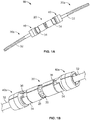
- FIGs. 1A-4B depict an intercalary prosthesis 10 according to an embodiment of the present disclosure.
- the intercalary prosthesis 10 generally includes a first intramedullary component 30a, a second intramedullary component 30b, and a connector component 20.
- the connector component 20 generally includes a body 21 and connectors disposed 22 at opposing ends of the body 21.
- the body 21 has an outer shell 29 and an inner lattice structure 50.
- the outer shell 29 is a solid metal material with a generally continuous outer surface.
- the outer shell 29 defines a hollow cavity 27 therein which is occupied by the lattice structure 50.
- the lattice structure 50 is connected to the outer shell 29 and provides structural support to the connector component 20 while also providing reduced weight as compared to a connector component that is completely solid through its entire thickness.
- the lattice structure 50 is formed of a plurality of interconnected struts 52 which defined interstices 54 therebetween.
- the body 21 includes a plurality of openings 25 extending through the outer shell and into the inner cavity 27 so as to communicate with the lattice structure 50. This facilitates the removal of metallic powder from the cavity 27 after manufacturing via an additive manufacturing process, as described below.
- the body 21 also includes a plurality of flats 28 circumferentially arrayed about a longitudinal axis thereof. These flats 28 are angled relative to each other so that they can be engaged by a torque applying tool, such as a wrench, to facilitate the rotation of the connector component in-situ.
- the openings 25 in the body 21 each extend through a corresponding flat 28. However, in other embodiments, the openings 25 may extend through other regions of the body 21.
- the body 21 may have a patient specific curvature or bow.
- femurs typically have an anterior curvature or bow.
- the body 21 may be manufactured such that it matches the curvature or bow of the patient's particular anatomy.
- connector component 20 may have a longitudinal axis that is curved about a center of curvature which would be positioned posterior to the body 21.
- An anterior groove 21a as shown in FIG. 2A , may be aligned with this curvature so as to provide the surgeon the appropriate orientation.
- the anterior groove 26 may have an axis that is coplanar with the center of curvature.
- the connectors 22 extend from opposing ends of the body 21 and are male connectors. More particularly, these male connectors 22 are comprised of a post 22a and one or more spline keys 22b extending radially outwardly from the post 22a. As best shown in FIGs. 2B and 2C , a through-opening 24 extends through the entire length of connector component 20 and through the center of each of the connectors 22. Such through-opening 24 communicates with the lattice structure 50 and provides an additional egress route for powder removal.
- the connector component 20 is formed layer-by-layer using additive layer manufacturing (ALM), i.e., 3D printing, process so no separate connection mechanism is necessary to bring together any of the multiple features of the implant, such as the connectors, shell and lattice structure.
- ALM processes are powder-bed based and involve one or more of selective laser sintering (SLS), selective laser melting (SLM), and electron beam melting (EBM), as disclosed in U.S. Pat. Nos. 7,537,664 ; 8,728,387 ; 9,180,010 ; and 9,456,901 , the disclosures of which are hereby incorporated by reference in their entireties herein.
- the ALM process used to form the connector component 20 allows the creation of the lattice structure 50 which is completely surrounded by the outer shell 29. This allows the connector component 20 to be lighter weight than a connector component made from traditional manufacturing processes, such as machining, forging and casting, without sacrificing strength.
- the openings 25 in the body 21 and through-opening 24 facilitate the removal of loose powder from within the lattice structure after the connector component has been made.
- the use of ALM allows for a custom or semi-custom design. In preparing such an implant, the patient's anatomy around at least the region for treatment may be scanned, such as by a CT scan or other use of x-rays or by magnetic resonance imaging (MRI) or other known imaging device.
- MRI magnetic resonance imaging
- the scanned image may then be converted to virtual patient-specific bone image using computer-aided modeling and segmentation software.
- Such software may be but is not limited to ImorphicsTM, which is wholly owned by Imorphics Limited, a subsidiary of Stryker ® Corporation, Stryker ® Orthopaedics Modeling and Analytics (SOMA) by Stryker ® Corporation, GeoMagic ® by 3D Systems, Inc., and 3D Slicer software developed by the Massachusetts Institute of Technology.
- a manual segmentation or an automatic segmentation process such as either of the processes described in U.S. Patent No. 7,584,080 and U.S. Patent Application Publication No. 2011/0194739 A1 , which are hereby incorporated by reference in their entireties herein, may be used.
- a virtual connector component 20 would then be manipulated in the virtual space to match certain aspects of the patient's anatomy, such as an anterior curvature of the patient's femur, also known as an anterior bow, which is discussed above.
- the virtual component 20 could then be printed with those same features using ALM.
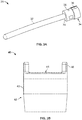
- the first and second stem assemblies 30a-b each generally include a stem component 32 and a modular collar 40.
- the stem component 31 includes an intramedullary stem 32, integral collar 38, and a connector 34.
- the stem 32 may have flutes (not shown) for anti-rotation or indented elongate grooves for strength.
- the integral collar 38 is positioned between the stem 32 and connector 34.
- the integral collar 38 has a larger cross-sectional dimension than the stem 32 and may have a tapered outer surface.
- collar 38 may have a tapered inner diameter to facilitate a taper-lock connection to the stem 32.
- the connector 20 may have a larger cross-sectional dimension than the integral collar 38 so as to form a shoulder 39 which acts as a stop for the modular collar 40.
- the connector 34 also has a plurality of notches 36 on its exterior for receipt of the tabs 46 of the modular collar, as discussed below.
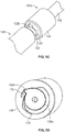
- the connector 34 as best shown in FIGs. 4A and 4B , is a female connector. As a female connector, it has an opening 33 for receipt of the male connector 22 of the connector component 20. Such opening 33 has notches 37 configured to receive the splines 22b of the male connector 22 in one orientation, as best shown in FIG. 4A .
- a spiraled groove 35 which has one or more surfaces, depending on the number of splines 22b, which each have a progressively smaller radius so as to interfere with a corresponding spline 22b in order lock the male and female connectors 20, 34 together, as best shown in FIG. 4B .
- the modular collar 40 has a body 42 with a porous outer surface 43 and an opening extending 44 entirely through the body 42 along a length of the modular collar 40.
- the through-opening 44 may be tapered so as to facilitate a taper lock between the integral collar 38 and modular collar 40.
- Tabs 46 extend from one end of the body 42 and may be received within the notches 36 in the connector 34 so as to prohibit rotation of the modular collar 40 relative to the stem component 31.
- the connector component 20 is positioned between the first and second intramedullary components 30a, 30b and locked thereto via the corresponding connectors 22, 34, as shown in FIGs. 1A and 1B .
- the modular collars 40 are positioned over the respective integral collars 38 of the stem components 30a, 30b.
- the connector component 20 facilitates the assembly of the endoprosthesis in-situ.
- the first and second intramedullary components 30a-b are implanted into respective bone portions.
- a femur may include a first or proximal bone portion and a second or distal bone portion.
- the stem 32 of the first intramedullary component 30a may be inserted into the intramedullary canal of the first bone portion, such as in a press-fit or cemented manner.
- the stem 32 of the second intramedullary component 30b may be inserted into the intramedullary canal of the second bone portion, also in a press-fit or cemented manner.
- the first and second intramedullary components 30a-b may be implanted such that the modular collars 40, which are assembled to the stem components 30a-b prior to implantation, abut the ends of the respective bone portions.
- the bone may grow into the porous structures 42 of the modular collars 40.
- the connector component 20 is positioned between the intramedullary components 30a-b.
- the connectors 22 of the connector component 20 are then inserted into the connectors 34 of the respective intramedullary components 30a-b, as best shown in FIG. 4A .
- splines 22b pass through notches 37.
- the connector component 20 may be rotated such as via a wrench or the like which causes the splines 22b to engage the spiral grooves 35 thereby locking the connector component 20 to the intramedullary components 30a-b, as best shown in FIG. 4B .
- the connector component 20 and intramedullary components 30a-b are oriented prior to rotation in a way that once the connector component 20 is rotated into the locked position, the anterior groove 26 faces anterior so that the bow of the connector component 20 aligns with the bow of the patient's femur.
- FIGs. 5A-5C depict a connector component 120 and intramedullary component 130a according to another embodiment of the disclosure. Like elements are accorded like reference numerals to that of connector component 20 and intramedullary components 130a-b but within the 100 series of numbers. In this configuration, the connector component 120 and first and second intramedullary components 130a-b respectively include male and female connectors 122, 134 at their ends. FIGs. 5A-5C only depicts the first intramedullary components 130a which is representative of the second intramedullary component 130b (not shown).
- the male connectors 122 at the ends of the connector component 120 is in the form of a snail cam defined by a spiral post 122a that has a reducing radius cam surface that terminates at a tooth 122b.
- the female connectors 134 at the ends of the intramedullary components 130a-b have a grooved opening 133 with a leaf spring 135 that extends into the opening 133, as shown in FIG. 5B .
- the connectors 122 of the connector component 120 are inserted into corresponding female connectors 134 of the intramedullary components 130a-b, as illustrated in FIG. 5C .
- the connector component 120 is rotated about its axis in the same manner described above. This causes the cam surfaces to push the leaf spring 135 radially outwardly.
- the tooth 122b passes the leaf spring 135, the leaf spring 135 snaps back into its original position.
- the tooth 122b now extends further radially outwardly than the leaf spring 135 which prohibits rotation of the connector component 120 in the opposite direction thereby locking the connector component 120 to the intramedullary components 130a-b.
- the male connector of connector component 20 may instead be located at the ends of intramedullary components 30a-b, while the female connectors of components 30a-b may be located at the ends of connector component 20.
- the connection is functionally the same as that of components 20 and 30a-b but with the male/female connectors 22, 34 being swapped between components 20 and 30a-b.
- Such reverse configuration of male/female connectors is also contemplated for connector component 120 and intramedullary components 130a-b.
Landscapes
- Health & Medical Sciences (AREA)
- Orthopedic Medicine & Surgery (AREA)
- Life Sciences & Earth Sciences (AREA)
- Animal Behavior & Ethology (AREA)
- Veterinary Medicine (AREA)
- Engineering & Computer Science (AREA)
- Biomedical Technology (AREA)
- Heart & Thoracic Surgery (AREA)
- Public Health (AREA)
- General Health & Medical Sciences (AREA)
- Surgery (AREA)
- Cardiology (AREA)
- Oral & Maxillofacial Surgery (AREA)
- Transplantation (AREA)
- Vascular Medicine (AREA)
- Molecular Biology (AREA)
- Medical Informatics (AREA)
- Nuclear Medicine, Radiotherapy & Molecular Imaging (AREA)
- Neurology (AREA)
- Prostheses (AREA)
- Surgical Instruments (AREA)
Abstract
Description
- Intercalary skeletal defects may result from trauma or resection of diaphyseal bone tumors in long bones, such as a femur, tibia, and the like. In this regard, a segment of damaged or diseased bone between two joints may be completely removed so that the long bone is no longer one continuous bone extending from joint to joint, but is instead divided into two healthy bone segments. Since it is desirable to keep as much healthy bone as possible, particularly at the joints, it is necessary to join the healthy bone segments together through a reconstruction process. However, this presents reconstructive challenges for orthopedic surgeons as they have to ensure a stable structure, which may be load bearing, while also accounting for the missing bone, the length of which varies from patient to patient.
- Various reconstruction implants have been developed over the years to salvage the healthy bone. However, such implants are typically not patient specific and therefore may leave the patient with awkward bone geometries and a longer or shorter limb than prior to their disease or injury. Additionally, such implants are often heavy as compared to bone and may be difficult to implant and assemble in-situ as the healthy bone segments can be distracted only so far. Thus, further improvements are desirable.
- In one aspect of the present disclosure, an intercalary prosthesis for spanning portions of a long bone include an intramedullary component that has a first stem and a first connector disposed at one end of the first stem. The first stem is configured to be received within an intramedullary canal of a long bone. The prosthesis also includes a second intramedullary component that has second stem and a second connector disposed at one end of the second stem. The second stem is configured to be received within an intramedullary canal of the long bone. The prosthesis further includes a connector component that has a body. The body has opposing ends each with a connector configured to respectively connect to the connectors of the first and second intramedullary components. The body has an outer shell and an inner lattice structure disposed within and connected to the outer shell.
- Additionally, the first and second intramedullary components may each include a modular collar and an integral collar. The modular collar may be connectable to the integral collar and may have an outer surface that comprises a porous structure. The integral collar of the first intramedullary component may be disposed between the first stem and first connector portion. The body of the connector component may also include a plurality of openings extending through the outer shell to the inner lattice structure. The lattice structure may be comprised of a plurality of interconnected struts forming interstices therebetween. The connector component may further include a plurality of flats circumferentially arrayed about a longitudinal axis of the connector for engagement by a torque applying tool.
- Continuing with this aspect, the body may be bowed such that a longitudinal axis thereof is curved about a center of curvature. The body may include an anterior groove that is coplanar with the center of curvature. The first and second connectors may each be a female connector, and the connectors of the connector component may be male connectors extending from opposing ends of the body. The male connectors may be configured to be respectively received within the female connectors and locked thereto upon rotation of the connector component relative to the first and second intramedullary components. The first and second connectors may each be a male connector respectively extending from the first and second stems. The connectors of the connector component may be female connectors disposed at opposing ends of the body. The male connectors may be configured to be respectively received within the female connectors and locked thereto upon rotation of the connector component relative to the first and second intramedullary components.
- In another aspect of the present disclosure, an intercalary prosthesis for spanning portions of a long bone includes a first intramedullary component that has a first stem and a first connector disposed at one end of the first stem. The first stem is configured to be received within an intramedullary canal of a long bone. The prosthesis also includes a second intramedullary component that has a second stem and a second connector disposed at one end of the second stem. The second stem is configured to be received within an intramedullary canal of the long bone. The prosthesis further includes a connector component that has a body and third and fourth connectors disposed at opposed ends of the body. The first and third connectors and second and fourth connectors are configured to be locked to each other upon rotation of the connector component relative to the first and second intramedullary components.
- Additionally, the first and second connectors may each be a female connector, and the third and fourth connectors of the connector component may be male connectors extending from opposing ends of the body. The male connectors may be configured to be respectively received within the female connectors and locked thereto upon rotation of the connector component relative to the first and second intramedullary components. The male connectors may include a post and spline keys extending from the post, and the female connectors may include a spiraled recess configured to interfere with the spline keys when rotated within the spiraled recess for providing a locking connection. Alternatively, the male connectors may include a cam surface and a tooth, and the female connectors may include a recess with a leaf spring extending therein. The cam surface may be configured to move the leaf spring radially outwardly upon rotation of the male connectors in a first direction. The tooth may be configured to engage the leaf spring to prevent rotation of the male connectors in a second direction.
- Continuing with this aspect, the first and second connectors may each be a male connector respectively extending from the first and second stem, and the third and fourth connectors of the connector component may be female connectors disposed at opposing ends of the body. The male connectors may be configured to be respectively received within the female connectors and locked thereto upon rotation of the connector component relative to the first and second intramedullary components. The male connectors may include a post and spline keys extending from the post, and the female connectors may include a spiraled recess configured to interfere with the spline keys when rotated within the spiraled recess. Alternatively, the male connectors may include cam surface and a tooth, and the female connectors may include a recess with a leaf spring extending therein. The cam surface may be configured to move the leaf spring radially outwardly upon rotation of the male connectors in a first direction. The tooth may be configured to engage the leaf spring to prevent rotation of the male connectors in a second direction. The body of the connector component may include a solid shell surrounding a lattice structure.
- In a further aspect of the present disclosure, a method of connecting first and second portions of a long bone includes: inserting a first stem of a first intramedullary component into a first portion of a long bone and a second stem of a second intramedullary component into a second portion of the long bone. After the inserting step, the method includes connecting a first end of a connector component to an end of the first intramedullary component and a second end of the connector component to an end of the second intramedullary component.
- Additionally, the connecting step may include rotating the connector to lock the first and second intramedullary components to the connector component. The connecting step may also include inserting male connectors each extending from opposing ends of a body of the connector component into respective female connectors of the first and second intramedullary components. Alternatively, the connecting step may include inserting male connectors each extending from a respective end of the first and second intramedullary components into respective female connectors of the connector component. The female connectors may be disposed at opposing ends of a body of the connector component.
- The features, aspects, and advantages of the present invention will become better understood with regard to the following description, appended claims, and accompanying drawings in which:
-
FIG. 1A is a perspective view of an intercalary prosthesis according to an embodiment of the present disclosure. -
FIG. 1B is a partial perspective view of the prosthesis ofFIG. 1A . -
FIG. 2A is a perspective view of a connector component of the prosthesis ofFIG. 1A . -
FIG. 2B is a cross-sectional view of the connector component ofFIG. 2A taken along a midline thereof and absent a lattice structure. -
FIG. 2c is a cross-sectional view of the connector component ofFIG. 2A taken along a midline thereof and including a lattice structure. -
FIG. 3A is a perspective view of a stem component of the prosthesis ofFIG. 1A . -
FIG. 3B is front elevational view of modular collar of the prosthesis ofFIG. 1A . -
FIG. 4A is a cross-sectional view of the connector component and stem component ofFIGS. 2A and3A while being assembled. -
FIG. 4B is a cross-sectional view of the connector component and stem component ofFIGS. 2A and3A as assembled. -
FIG. 5A is a perspective view of a connector component according to another embodiment of the present disclosure. -
FIG. 5B is a cross-sectional view of a stem component according to another embodiment of the present disclosure. -
FIG. 5C is an exploded view of the connector component and stem component ofFIGS. 5A and 5B . -
FIG. 5D is a cross-sectional view of the connector component and stem component ofFIG. 5A and 5B as assembled. - When referring to specific directions in the following discussion of certain implantable devices, it should be understood that such directions are described with regard to the implantable device's orientation and position during exemplary application to the human body. Thus, as used herein, the term "proximal" means close to the heart and the term "distal" means more distant from the heart. The term "inferior" means toward the feet and the term "superior" means toward the head. The term "anterior" means toward the front of the body or the face, and the term "posterior" means toward the back of the body. The term "medial" means toward the midline of the body, and the term "lateral" means away from the midline of the body. Also, as used herein, the terms "about," "generally" and "substantially" are intended to mean that slight deviations from absolute are included within the scope of the term so modified.
-
FIGs. 1A-4B depict anintercalary prosthesis 10 according to an embodiment of the present disclosure. Theintercalary prosthesis 10 generally includes a firstintramedullary component 30a, a secondintramedullary component 30b, and aconnector component 20. - The
connector component 20 generally includes abody 21 and connectors disposed 22 at opposing ends of thebody 21. Thebody 21 has anouter shell 29 and aninner lattice structure 50. Theouter shell 29 is a solid metal material with a generally continuous outer surface. Theouter shell 29 defines ahollow cavity 27 therein which is occupied by thelattice structure 50. Thelattice structure 50 is connected to theouter shell 29 and provides structural support to theconnector component 20 while also providing reduced weight as compared to a connector component that is completely solid through its entire thickness. Thelattice structure 50 is formed of a plurality ofinterconnected struts 52 which definedinterstices 54 therebetween. - The
body 21 includes a plurality ofopenings 25 extending through the outer shell and into theinner cavity 27 so as to communicate with thelattice structure 50. This facilitates the removal of metallic powder from thecavity 27 after manufacturing via an additive manufacturing process, as described below. Thebody 21 also includes a plurality offlats 28 circumferentially arrayed about a longitudinal axis thereof. Theseflats 28 are angled relative to each other so that they can be engaged by a torque applying tool, such as a wrench, to facilitate the rotation of the connector component in-situ. In the particular embodiment depicted, theopenings 25 in thebody 21 each extend through a corresponding flat 28. However, in other embodiments, theopenings 25 may extend through other regions of thebody 21. - In addition, the
body 21 may have a patient specific curvature or bow. For example, femurs typically have an anterior curvature or bow. Thebody 21 may be manufactured such that it matches the curvature or bow of the patient's particular anatomy. In this regard,connector component 20 may have a longitudinal axis that is curved about a center of curvature which would be positioned posterior to thebody 21. An anterior groove 21a, as shown inFIG. 2A , may be aligned with this curvature so as to provide the surgeon the appropriate orientation. In this regard, theanterior groove 26 may have an axis that is coplanar with the center of curvature. - As shown, the
connectors 22 extend from opposing ends of thebody 21 and are male connectors. More particularly, thesemale connectors 22 are comprised of apost 22a and one ormore spline keys 22b extending radially outwardly from thepost 22a. As best shown inFIGs. 2B and2C , a through-opening 24 extends through the entire length ofconnector component 20 and through the center of each of theconnectors 22. Such through-opening 24 communicates with thelattice structure 50 and provides an additional egress route for powder removal. - The
connector component 20 is formed layer-by-layer using additive layer manufacturing (ALM), i.e., 3D printing, process so no separate connection mechanism is necessary to bring together any of the multiple features of the implant, such as the connectors, shell and lattice structure. In some examples, ALM processes are powder-bed based and involve one or more of selective laser sintering (SLS), selective laser melting (SLM), and electron beam melting (EBM), as disclosed inU.S. Pat. Nos. 7,537,664 ;8,728,387 ;9,180,010 9,456,901 - The ALM process used to form the
connector component 20 allows the creation of thelattice structure 50 which is completely surrounded by theouter shell 29. This allows theconnector component 20 to be lighter weight than a connector component made from traditional manufacturing processes, such as machining, forging and casting, without sacrificing strength. Theopenings 25 in thebody 21 and through-opening 24 facilitate the removal of loose powder from within the lattice structure after the connector component has been made. In addition, the use of ALM allows for a custom or semi-custom design. In preparing such an implant, the patient's anatomy around at least the region for treatment may be scanned, such as by a CT scan or other use of x-rays or by magnetic resonance imaging (MRI) or other known imaging device. The scanned image may then be converted to virtual patient-specific bone image using computer-aided modeling and segmentation software. Such software may be but is not limited to ImorphicsTM, which is wholly owned by Imorphics Limited, a subsidiary of Stryker® Corporation, Stryker® Orthopaedics Modeling and Analytics (SOMA) by Stryker® Corporation, GeoMagic® by 3D Systems, Inc., and 3D Slicer software developed by the Massachusetts Institute of Technology. A manual segmentation or an automatic segmentation process, such as either of the processes described inU.S. Patent No. 7,584,080 andU.S. Patent Application Publication No. 2011/0194739 A1 , which are hereby incorporated by reference in their entireties herein, may be used. Avirtual connector component 20 would then be manipulated in the virtual space to match certain aspects of the patient's anatomy, such as an anterior curvature of the patient's femur, also known as an anterior bow, which is discussed above. Thevirtual component 20 could then be printed with those same features using ALM. - The first and
second stem assemblies 30a-b each generally include astem component 32 and amodular collar 40. Thestem component 31 includes anintramedullary stem 32,integral collar 38, and aconnector 34. Thestem 32 may have flutes (not shown) for anti-rotation or indented elongate grooves for strength. Theintegral collar 38 is positioned between thestem 32 andconnector 34. Theintegral collar 38 has a larger cross-sectional dimension than thestem 32 and may have a tapered outer surface. For embodiments in whichcollar 38 is a separate component that couples withstem 32,collar 38 may have a tapered inner diameter to facilitate a taper-lock connection to thestem 32. - The
connector 20 may have a larger cross-sectional dimension than theintegral collar 38 so as to form ashoulder 39 which acts as a stop for themodular collar 40. Theconnector 34 also has a plurality ofnotches 36 on its exterior for receipt of thetabs 46 of the modular collar, as discussed below. Theconnector 34, as best shown inFIGs. 4A and 4B , is a female connector. As a female connector, it has anopening 33 for receipt of themale connector 22 of theconnector component 20.Such opening 33 hasnotches 37 configured to receive thesplines 22b of themale connector 22 in one orientation, as best shown inFIG. 4A . Within opening 33 is a spiraledgroove 35 which has one or more surfaces, depending on the number ofsplines 22b, which each have a progressively smaller radius so as to interfere with acorresponding spline 22b in order lock the male andfemale connectors FIG. 4B . - The
modular collar 40 has abody 42 with a porousouter surface 43 and an opening extending 44 entirely through thebody 42 along a length of themodular collar 40. The through-opening 44 may be tapered so as to facilitate a taper lock between theintegral collar 38 andmodular collar 40.Tabs 46 extend from one end of thebody 42 and may be received within thenotches 36 in theconnector 34 so as to prohibit rotation of themodular collar 40 relative to thestem component 31. - As assembled, the
connector component 20 is positioned between the first and secondintramedullary components connectors FIGs. 1A and 1B . Themodular collars 40 are positioned over the respectiveintegral collars 38 of thestem components - In a method of implantation, the
connector component 20 facilitates the assembly of the endoprosthesis in-situ. In this regard, the first and secondintramedullary components 30a-b are implanted into respective bone portions. For example, a femur may include a first or proximal bone portion and a second or distal bone portion. Thestem 32 of the firstintramedullary component 30a may be inserted into the intramedullary canal of the first bone portion, such as in a press-fit or cemented manner. Similarly, thestem 32 of the secondintramedullary component 30b may be inserted into the intramedullary canal of the second bone portion, also in a press-fit or cemented manner. The first and secondintramedullary components 30a-b may be implanted such that themodular collars 40, which are assembled to thestem components 30a-b prior to implantation, abut the ends of the respective bone portions. The bone may grow into theporous structures 42 of themodular collars 40. - Once the
intramedullary components 30a-b are implanted, theconnector component 20 is positioned between theintramedullary components 30a-b. Theconnectors 22 of theconnector component 20 are then inserted into theconnectors 34 of the respectiveintramedullary components 30a-b, as best shown inFIG. 4A . In this regard, splines 22b pass throughnotches 37. Oncesplines 22b are inserted passednotches 37, theconnector component 20 may be rotated such as via a wrench or the like which causes thesplines 22b to engage thespiral grooves 35 thereby locking theconnector component 20 to theintramedullary components 30a-b, as best shown inFIG. 4B . It is noted that theconnector component 20 andintramedullary components 30a-b are oriented prior to rotation in a way that once theconnector component 20 is rotated into the locked position, theanterior groove 26 faces anterior so that the bow of theconnector component 20 aligns with the bow of the patient's femur. -
FIGs. 5A-5C depict aconnector component 120 andintramedullary component 130a according to another embodiment of the disclosure. Like elements are accorded like reference numerals to that ofconnector component 20 andintramedullary components 130a-b but within the 100 series of numbers. In this configuration, theconnector component 120 and first and secondintramedullary components 130a-b respectively include male andfemale connectors FIGs. 5A-5C only depicts the firstintramedullary components 130a which is representative of the second intramedullary component 130b (not shown). Themale connectors 122 at the ends of theconnector component 120 is in the form of a snail cam defined by aspiral post 122a that has a reducing radius cam surface that terminates at atooth 122b. Thefemale connectors 134 at the ends of theintramedullary components 130a-b have a groovedopening 133 with aleaf spring 135 that extends into theopening 133, as shown inFIG. 5B . - In use, the
connectors 122 of theconnector component 120 are inserted into correspondingfemale connectors 134 of theintramedullary components 130a-b, as illustrated inFIG. 5C . Once themale connectors 122 are received within the correspondingfemale connectors 134, theconnector component 120 is rotated about its axis in the same manner described above. This causes the cam surfaces to push theleaf spring 135 radially outwardly. Once thetooth 122b passes theleaf spring 135, theleaf spring 135 snaps back into its original position. Thetooth 122b now extends further radially outwardly than theleaf spring 135 which prohibits rotation of theconnector component 120 in the opposite direction thereby locking theconnector component 120 to theintramedullary components 130a-b. - Other connector configurations are also contemplated but not shown. For example, the male connector of
connector component 20 may instead be located at the ends ofintramedullary components 30a-b, while the female connectors ofcomponents 30a-b may be located at the ends ofconnector component 20. In other words, the connection is functionally the same as that ofcomponents female connectors components connector component 120 andintramedullary components 130a-b. - Although the invention herein has been described with reference to particular embodiments, it is to be understood that these embodiments are merely illustrative of the principles and applications of the present invention. It is therefore to be understood that numerous modifications may be made to the illustrative embodiments and that other arrangements may be devised without departing from the spirit and scope of the present invention as defined by the appended claims.
Claims (15)
- An intercalary prosthesis for spanning portions of a long bone, comprising:a first intramedullary component having a first stem and a first connector disposed at one end of the first stem, the first stem being configured to be received within an intramedullary canal of a long bone;a second intramedullary component having a second stem and a second connector disposed at one end of the second stem, the second stem being configured to be received within an intramedullary canal of the long bone; anda connector component having a body, the body having opposing ends each having a connector configured to respectively connect to the connectors of the first and second intramedullary components, the body also having an outer shell and an inner lattice structure disposed within and connected to the outer shell.
- The prosthesis of claim 1, wherein the first and second intramedullary components each include a modular collar and an integral collar, the modular collar being connectable to the integral collar and having an outer surface comprising a porous structure.
- The prosthesis of claim 2, wherein the integral collar of the first intramedullary component is disposed between the first stem and first connector portion.
- The prosthesis as in any of the preceding claims, wherein the body of the connector component includes a plurality of openings extending through the outer shell to the inner lattice structure.
- The prosthesis as in any of the preceding claims, wherein the lattice structure is comprised of a plurality of interconnected struts forming interstices therebetween.
- The prosthesis as in any of the preceding claims, wherein the body of the connector component includes a plurality of flats circumferentially arrayed about a longitudinal axis of the connector for engagement by a torque applying tool.
- The prosthesis as in any of the preceding claims, wherein the body is bowed such that a longitudinal axis thereof is curved about a center of curvature.
- The prosthesis of claim 7, wherein the body includes an anterior groove that is coplanar with the center of curvature.
- The prosthesis as in any of the preceding claims, wherein the first and second connectors are each a female connector, and the connectors of the connector component are male connectors extending from opposing ends of the body, the male connectors being configured to be respectively received within the female connectors and locked thereto upon rotation of the connector component relative to the first and second intramedullary components.
- The prosthesis as in any of the preceding claims, wherein the first and second connectors are each a male connector respectively extending from the first and second stems, and the connectors of the connector component are female connectors disposed at opposing ends of the body, the male connectors being configured to be respectively received within the female connectors and locked thereto upon rotation of the connector component relative to the first and second intramedullary components.
- The prosthesis of claim 1, wherein the connectors are third and fourth connectors disposed at opposed ends of the body, the first and third connectors and second and fourth connectors are configured to be locked to each other upon rotation of the connector component relative to the first and second intramedullary components.
- The prosthesis of claim 11, wherein the first and second connectors are each a female connector, and the third and fourth connectors of the connector component are male connectors extending from opposing ends of the body, the male connectors being configured to be respectively received within the female connectors and locked thereto upon rotation of the connector component relative to the first and second intramedullary components.
- The prosthesis of claim 12, wherein the male connectors include a post and spline keys extending from the post, and the female connectors include a spiraled recess configured to interfere with the spline keys when rotated within the spiraled recess for providing a locking connection.
- The prosthesis of claim 12, wherein the male connectors include cam surface and a tooth, and the female connectors include a recess with a leaf spring extending therein, the cam surface being configured to move the leaf spring radially outwardly upon rotation of the male connectors in a first direction, the tooth being configured to engage the leaf spring to prevent rotation of the male connectors in a second direction.
- The prosthesis of claim 11, wherein the first and second connectors are each a male connector respectively extending from the first and second stem, and the third and fourth connectors of the connector component are female connectors disposed at opposing ends of the body, the male connectors being configured to be respectively received within the female connectors and locked thereto upon rotation of the connector component relative to the first and second intramedullary components.
Applications Claiming Priority (1)
| Application Number | Priority Date | Filing Date | Title |
|---|---|---|---|
| US202063034147P | 2020-06-03 | 2020-06-03 |
Publications (2)
| Publication Number | Publication Date |
|---|---|
| EP3932369A1 true EP3932369A1 (en) | 2022-01-05 |
| EP3932369B1 EP3932369B1 (en) | 2025-06-04 |
Family
ID=76250230
Family Applications (1)
| Application Number | Title | Priority Date | Filing Date |
|---|---|---|---|
| EP21177440.1A Active EP3932369B1 (en) | 2020-06-03 | 2021-06-02 | Intercalary endoprosthesis |
Country Status (3)
| Country | Link |
|---|---|
| US (1) | US12491072B2 (en) |
| EP (1) | EP3932369B1 (en) |
| AU (1) | AU2021203588A1 (en) |
Families Citing this family (2)
| Publication number | Priority date | Publication date | Assignee | Title |
|---|---|---|---|---|
| EP3838227B1 (en) * | 2019-12-16 | 2026-02-25 | Waldemar Link GmbH & Co. KG | Cement retaining implant stem for permanent fixation |
| CN118303961B (en) * | 2024-03-25 | 2024-10-18 | 中国人民解放军总医院第四医学中心 | Elastic intramedullary fixation device |
Citations (11)
| Publication number | Priority date | Publication date | Assignee | Title |
|---|---|---|---|---|
| US20050107794A1 (en) * | 2003-03-31 | 2005-05-19 | Hazebrouck Stephen A. | Orthopaedic spacer |
| US20060167554A1 (en) * | 2004-12-17 | 2006-07-27 | Heck Robert K | Modular implant system and method with diaphyseal implant |
| US7537664B2 (en) | 2002-11-08 | 2009-05-26 | Howmedica Osteonics Corp. | Laser-produced porous surface |
| US7584080B2 (en) | 2001-06-12 | 2009-09-01 | Imorphics Limited | Constructing a statistical shape model from two-dimensional or three-dimensional data |
| US20110194739A1 (en) | 2010-02-10 | 2011-08-11 | Imorphics Limited | Image analysis |
| US8728387B2 (en) | 2005-12-06 | 2014-05-20 | Howmedica Osteonics Corp. | Laser-produced porous surface |
| US9180010B2 (en) | 2012-04-06 | 2015-11-10 | Howmedica Osteonics Corp. | Surface modified unit cell lattice structures for optimized secure freeform fabrication |
| US20160228255A1 (en) * | 2007-08-27 | 2016-08-11 | Connor E Samuelson | Systems and methods for providing prosthetic components |
| US9456901B2 (en) | 2004-12-30 | 2016-10-04 | Howmedica Osteonics Corp. | Laser-produced porous structure |
| WO2018067085A2 (en) * | 2016-07-26 | 2018-04-12 | Estas Tibbi Mamulleri Medikal Cihazlar Otomotiv Imalat Ithalat Ihracat Ve Ticaret Sanayi Anonim Sirketi | Diaphyseal and arthrodesis endoprosthesis system |
| US20190192304A1 (en) * | 2017-12-23 | 2019-06-27 | Onkos Surgical, Inc. | Implant with ability to capture extravazating fixation medium |
Family Cites Families (51)
| Publication number | Priority date | Publication date | Assignee | Title |
|---|---|---|---|---|
| FR2158657A5 (en) | 1971-10-27 | 1973-06-15 | Rhone Poulenc Sa | |
| US3990116A (en) | 1974-10-17 | 1976-11-09 | Fixel Irving E | Pretensioned prosthetic device for skeletal joints |
| US4016874A (en) * | 1976-05-19 | 1977-04-12 | Maffei Ernest J | Three-part intramedullary bone-setting pin |
| US4467794A (en) * | 1982-02-08 | 1984-08-28 | Ernest Maffei | Intramedulary bone-setting assembly |
| FR2575059B1 (en) * | 1984-12-21 | 1988-11-10 | Daher Youssef | SHORING DEVICE FOR USE IN A VERTEBRAL PROSTHESIS |
| DE3528728A1 (en) * | 1985-08-09 | 1987-02-12 | Link Waldemar Gmbh Co | ENDOPROTHESIS TO REPLACE THE MEDIUM SECTION OF A LONG-STRETCHED BONE |
| US4787907A (en) * | 1987-02-03 | 1988-11-29 | Techmedica, Inc. | Morse taper |
| US4938768A (en) | 1987-03-09 | 1990-07-03 | Henry Ford Hospital | Bone gap bridging and fusing device |
| US5281226A (en) | 1989-03-31 | 1994-01-25 | Davydov Anatoly B | Missing portion of a tubular bone |
| US5211664A (en) | 1992-01-14 | 1993-05-18 | Forschungsinstitut, Davos Laboratorium Fur Experimentelle Chirugie | Shell structure for bone replacement |
| US5334184A (en) * | 1992-06-30 | 1994-08-02 | Bimman Lev A | Apparatus for intramedullary fixation broken bones |
| US5352227A (en) * | 1993-02-03 | 1994-10-04 | Howmedica Inc. | Intercalary device |
| US7141073B2 (en) * | 1993-11-01 | 2006-11-28 | Biomet, Inc. | Compliant fixation of external prosthesis |
| US5499985A (en) | 1993-11-24 | 1996-03-19 | Orthopaedic Innovations, Inc. | Detachable coupling system for surgical instruments |
| US5626580A (en) | 1994-07-15 | 1997-05-06 | Brosnahan; Robert | Multi-section intramedullary nail |
| PT729732E (en) | 1995-03-03 | 2003-12-31 | Levante Ind Quirurgicas | OSSSEA REPLACEMENT PROTECTION OF MODULAR CONCEPTION |
| US6364909B1 (en) * | 1995-07-18 | 2002-04-02 | Iowa State University Research Foundation, Inc. | Method of restructuring bone |
| DE19633865A1 (en) * | 1996-08-16 | 1998-02-19 | Guenter Prof Dr Med Lob | Endoprosthesis |
| US6613092B1 (en) * | 2000-07-19 | 2003-09-02 | Centerpulse Orthopedics Inc. | Stem taper adapter |
| GB0102141D0 (en) | 2001-01-27 | 2001-03-14 | Davies John B C | Improvements in or relating to expandable bone nails |
| US7182786B2 (en) | 2002-04-25 | 2007-02-27 | Zimmer Technology, Inc. | Modular bone implant, tool, and method |
| US20030204267A1 (en) | 2002-04-30 | 2003-10-30 | Hazebrouck Stephen A. | Modular limb preservation system |
| US7001386B2 (en) * | 2002-07-23 | 2006-02-21 | Advanced Orthopaedic Solutions, Inc. | Intramedullary nail for long bone fractures |
| DE10238306B4 (en) * | 2002-08-21 | 2005-03-24 | Biedermann Motech Gmbh | Method for producing a tubular spacer and placeholder |
| US7141067B2 (en) * | 2003-03-31 | 2006-11-28 | Depuy Products, Inc. | Intercalary implant |
| US7125423B2 (en) * | 2003-03-31 | 2006-10-24 | Depuy Products, Inc. | Intercalary prosthesis, kit and method |
| US7153326B1 (en) * | 2003-06-19 | 2006-12-26 | Biomet Manufacturing Corp. | Method and apparatus for use of an offset stem connection |
| US7435263B2 (en) * | 2003-09-30 | 2008-10-14 | Depuy Products, Inc. | Modular long bone prosthesis for partial or total bone replacement |
| US7867282B2 (en) * | 2004-12-17 | 2011-01-11 | Depuy Products, Inc. | Modular implant system and method with diaphyseal implant and adapter |
| AU2005316640B2 (en) | 2004-12-17 | 2011-06-09 | Depuy Products, Inc. | Modular diaphyseal and collar implant |
| US7998218B1 (en) * | 2005-02-02 | 2011-08-16 | Biomet Manufacturing Corp. | Modular orthopedic implant |
| WO2006094558A1 (en) * | 2005-03-11 | 2006-09-14 | Siemens Ag Österreich | Method and system for the alignment of an earth station antenna with a satellite antenna |
| US8568413B2 (en) * | 2008-12-18 | 2013-10-29 | Sonoma Orthopedic Products, Inc. | Bone fixation device, tools and methods |
| US9327056B2 (en) * | 2006-02-14 | 2016-05-03 | Washington State University | Bone replacement materials |
| EP2289469B1 (en) * | 2006-07-14 | 2012-06-27 | Biedermann Technologies GmbH & Co. KG | A spacer for insertion between two vertebrae |
| US7909883B2 (en) * | 2007-02-21 | 2011-03-22 | Sidebotham Christopher G | Percutaneous implant for limb salvage |
| CN103271761B (en) * | 2008-01-14 | 2015-10-28 | 康文图斯整形外科公司 | For the apparatus and method of fracture repair |
| DE102008045291B4 (en) | 2008-09-02 | 2013-05-02 | Merete Medical Gmbh | Knee arthrodesis implant |
| DE102008049123B4 (en) * | 2008-09-26 | 2013-06-06 | Merete Medical Gmbh | Modular joint prosthesis |
| US20110112649A1 (en) | 2009-11-09 | 2011-05-12 | Biomet Manufacturing Corp. | Radial and ulnar replacement |
| WO2012068062A1 (en) * | 2010-11-15 | 2012-05-24 | Synthes Usa, Llc | Graft collection and containment system for bone defects |
| EP2691048B1 (en) | 2011-03-29 | 2019-05-08 | Smith & Nephew, Inc. | Fracture fixation systems having intramedullary support |
| US8968415B2 (en) * | 2012-02-07 | 2015-03-03 | Biomet Manufacturing, Llc | Implant fixation device |
| WO2014022506A1 (en) * | 2012-08-01 | 2014-02-06 | Exactech, Inc. | Prosthetic devices to improve joint mechanics in arthroplasty |
| US10610368B2 (en) * | 2018-05-26 | 2020-04-07 | Acumed Llc | Ankle fusion system with expandable spacer |
| US9597203B2 (en) * | 2015-03-25 | 2017-03-21 | Tornier, Inc. | Modular humeral implant |
| US20160346018A1 (en) | 2015-06-01 | 2016-12-01 | The Texas A &M University System | Defect fixation device |
| JP7084879B2 (en) * | 2016-02-26 | 2022-06-15 | アクティボーソ, インコーポレイテッド | Active compressor, how to assemble, and how to use |
| BR112018075423A2 (en) * | 2016-06-13 | 2019-03-12 | DePuy Synthes Products, Inc. | bone graft cage |
| GB201614171D0 (en) | 2016-08-18 | 2016-10-05 | Fitzbionics Ltd | An implant for repair of bone defects |
| US10980580B2 (en) * | 2017-06-05 | 2021-04-20 | Biomet Manufacturing, Llc | Arthrodesis/intercallary/short stem limb salvage implant |
-
2021
- 2021-06-02 EP EP21177440.1A patent/EP3932369B1/en active Active
- 2021-06-02 US US17/336,571 patent/US12491072B2/en active Active
- 2021-06-02 AU AU2021203588A patent/AU2021203588A1/en active Pending
Patent Citations (11)
| Publication number | Priority date | Publication date | Assignee | Title |
|---|---|---|---|---|
| US7584080B2 (en) | 2001-06-12 | 2009-09-01 | Imorphics Limited | Constructing a statistical shape model from two-dimensional or three-dimensional data |
| US7537664B2 (en) | 2002-11-08 | 2009-05-26 | Howmedica Osteonics Corp. | Laser-produced porous surface |
| US20050107794A1 (en) * | 2003-03-31 | 2005-05-19 | Hazebrouck Stephen A. | Orthopaedic spacer |
| US20060167554A1 (en) * | 2004-12-17 | 2006-07-27 | Heck Robert K | Modular implant system and method with diaphyseal implant |
| US9456901B2 (en) | 2004-12-30 | 2016-10-04 | Howmedica Osteonics Corp. | Laser-produced porous structure |
| US8728387B2 (en) | 2005-12-06 | 2014-05-20 | Howmedica Osteonics Corp. | Laser-produced porous surface |
| US20160228255A1 (en) * | 2007-08-27 | 2016-08-11 | Connor E Samuelson | Systems and methods for providing prosthetic components |
| US20110194739A1 (en) | 2010-02-10 | 2011-08-11 | Imorphics Limited | Image analysis |
| US9180010B2 (en) | 2012-04-06 | 2015-11-10 | Howmedica Osteonics Corp. | Surface modified unit cell lattice structures for optimized secure freeform fabrication |
| WO2018067085A2 (en) * | 2016-07-26 | 2018-04-12 | Estas Tibbi Mamulleri Medikal Cihazlar Otomotiv Imalat Ithalat Ihracat Ve Ticaret Sanayi Anonim Sirketi | Diaphyseal and arthrodesis endoprosthesis system |
| US20190192304A1 (en) * | 2017-12-23 | 2019-06-27 | Onkos Surgical, Inc. | Implant with ability to capture extravazating fixation medium |
Also Published As
| Publication number | Publication date |
|---|---|
| EP3932369B1 (en) | 2025-06-04 |
| US20210378827A1 (en) | 2021-12-09 |
| US12491072B2 (en) | 2025-12-09 |
| AU2021203588A1 (en) | 2021-12-23 |
Similar Documents
| Publication | Publication Date | Title |
|---|---|---|
| US7125423B2 (en) | Intercalary prosthesis, kit and method | |
| EP1470799B1 (en) | Intercalary implant | |
| US5702487A (en) | Prosthetic device | |
| US5156627A (en) | Collarless femoral hip prosthesis | |
| US6432110B1 (en) | Modular trial instrument with interlock mechanism | |
| US6508840B1 (en) | Collarless shoulder arthroplasty prosthesis | |
| JP6227247B2 (en) | Artificial femoral stem for use in impact-resistant hip replacement surgery | |
| US5653764A (en) | Modular hip prosthesis with discrete selectable angular orientation | |
| AU2026203249A1 (en) | Shoulder prosthesis components and assemblies | |
| US7198642B2 (en) | Orthopaedic spacer | |
| JPH02109556A (en) | Module type artificial leg | |
| JP2000185062A (en) | Prosthesis system and modular sleeve | |
| EP3932369B1 (en) | Intercalary endoprosthesis | |
| US12115084B2 (en) | Method of installing a knee cone augment in an orthopaedic surgical procedure | |
| WO1985003426A1 (en) | Apparatus for affixing a prosthesis to bone | |
| US5080679A (en) | Orthopedic junction for dissimilar materials | |
| EP4312888B1 (en) | 3d printed monoblock orthopaedic surgical implant with customized patient-specific augment | |
| JP2007508063A (en) | Tapered joint prosthesis | |
| CN117794472A (en) | Femoral hip stem implants and corresponding orthopedic broaches | |
| US20150081028A1 (en) | Adaptor for modular joint prostheses | |
| US12478477B2 (en) | Modular tibial cone augments and method of surgically using the same | |
| US20240207062A1 (en) | Segmented keel for prosthetic implant having a stem | |
| US20220117745A1 (en) | Self-Broaching Neck Preserving Hip Stem | |
| US20230040129A1 (en) | Dynamic Bone Loading TKA | |
| US20240252217A1 (en) | Kit for the installation of prosthetic components and/or biomedical implants |
Legal Events
| Date | Code | Title | Description |
|---|---|---|---|
| PUAI | Public reference made under article 153(3) epc to a published international application that has entered the european phase |
Free format text: ORIGINAL CODE: 0009012 |
|
| STAA | Information on the status of an ep patent application or granted ep patent |
Free format text: STATUS: REQUEST FOR EXAMINATION WAS MADE |
|
| 17P | Request for examination filed |
Effective date: 20210602 |
|
| AK | Designated contracting states |
Kind code of ref document: A1 Designated state(s): AL AT BE BG CH CY CZ DE DK EE ES FI FR GB GR HR HU IE IS IT LI LT LU LV MC MK MT NL NO PL PT RO RS SE SI SK SM TR |
|
| B565 | Issuance of search results under rule 164(2) epc |
Effective date: 20211203 |
|
| GRAP | Despatch of communication of intention to grant a patent |
Free format text: ORIGINAL CODE: EPIDOSNIGR1 |
|
| STAA | Information on the status of an ep patent application or granted ep patent |
Free format text: STATUS: GRANT OF PATENT IS INTENDED |
|
| RIC1 | Information provided on ipc code assigned before grant |
Ipc: A61F 2/30 20060101ALN20250122BHEP Ipc: A61B 17/72 20060101ALI20250122BHEP Ipc: A61F 2/28 20060101AFI20250122BHEP |
|
| INTG | Intention to grant announced |
Effective date: 20250204 |
|
| RAP3 | Party data changed (applicant data changed or rights of an application transferred) |
Owner name: HOWMEDICA OSTEONICS CORP. |
|
| GRAS | Grant fee paid |
Free format text: ORIGINAL CODE: EPIDOSNIGR3 |
|
| GRAA | (expected) grant |
Free format text: ORIGINAL CODE: 0009210 |
|
| STAA | Information on the status of an ep patent application or granted ep patent |
Free format text: STATUS: THE PATENT HAS BEEN GRANTED |
|
| AK | Designated contracting states |
Kind code of ref document: B1 Designated state(s): AL AT BE BG CH CY CZ DE DK EE ES FI FR GB GR HR HU IE IS IT LI LT LU LV MC MK MT NL NO PL PT RO RS SE SI SK SM TR |
|
| REG | Reference to a national code |
Ref country code: GB Ref legal event code: FG4D |
|
| REG | Reference to a national code |
Ref country code: CH Ref legal event code: EP |
|
| P01 | Opt-out of the competence of the unified patent court (upc) registered |
Free format text: CASE NUMBER: APP_22051/2025 Effective date: 20250508 |
|
| REG | Reference to a national code |
Ref country code: DE Ref legal event code: R096 Ref document number: 602021031629 Country of ref document: DE |
|
| REG | Reference to a national code |
Ref country code: IE Ref legal event code: FG4D |
|
| REG | Reference to a national code |
Ref country code: NL Ref legal event code: MP Effective date: 20250604 |
|
| PG25 | Lapsed in a contracting state [announced via postgrant information from national office to epo] |
Ref country code: ES Free format text: LAPSE BECAUSE OF FAILURE TO SUBMIT A TRANSLATION OF THE DESCRIPTION OR TO PAY THE FEE WITHIN THE PRESCRIBED TIME-LIMIT Effective date: 20250604 Ref country code: FI Free format text: LAPSE BECAUSE OF FAILURE TO SUBMIT A TRANSLATION OF THE DESCRIPTION OR TO PAY THE FEE WITHIN THE PRESCRIBED TIME-LIMIT Effective date: 20250604 |
|
| REG | Reference to a national code |
Ref country code: LT Ref legal event code: MG9D |
|
| PG25 | Lapsed in a contracting state [announced via postgrant information from national office to epo] |
Ref country code: NO Free format text: LAPSE BECAUSE OF FAILURE TO SUBMIT A TRANSLATION OF THE DESCRIPTION OR TO PAY THE FEE WITHIN THE PRESCRIBED TIME-LIMIT Effective date: 20250904 Ref country code: GR Free format text: LAPSE BECAUSE OF FAILURE TO SUBMIT A TRANSLATION OF THE DESCRIPTION OR TO PAY THE FEE WITHIN THE PRESCRIBED TIME-LIMIT Effective date: 20250905 |
|
| PG25 | Lapsed in a contracting state [announced via postgrant information from national office to epo] |
Ref country code: PL Free format text: LAPSE BECAUSE OF FAILURE TO SUBMIT A TRANSLATION OF THE DESCRIPTION OR TO PAY THE FEE WITHIN THE PRESCRIBED TIME-LIMIT Effective date: 20250604 |
|
| PG25 | Lapsed in a contracting state [announced via postgrant information from national office to epo] |
Ref country code: BG Free format text: LAPSE BECAUSE OF FAILURE TO SUBMIT A TRANSLATION OF THE DESCRIPTION OR TO PAY THE FEE WITHIN THE PRESCRIBED TIME-LIMIT Effective date: 20250604 |
|
| PG25 | Lapsed in a contracting state [announced via postgrant information from national office to epo] |
Ref country code: HR Free format text: LAPSE BECAUSE OF FAILURE TO SUBMIT A TRANSLATION OF THE DESCRIPTION OR TO PAY THE FEE WITHIN THE PRESCRIBED TIME-LIMIT Effective date: 20250604 |
|
| PG25 | Lapsed in a contracting state [announced via postgrant information from national office to epo] |
Ref country code: RS Free format text: LAPSE BECAUSE OF FAILURE TO SUBMIT A TRANSLATION OF THE DESCRIPTION OR TO PAY THE FEE WITHIN THE PRESCRIBED TIME-LIMIT Effective date: 20250904 |
|
| PG25 | Lapsed in a contracting state [announced via postgrant information from national office to epo] |
Ref country code: LV Free format text: LAPSE BECAUSE OF FAILURE TO SUBMIT A TRANSLATION OF THE DESCRIPTION OR TO PAY THE FEE WITHIN THE PRESCRIBED TIME-LIMIT Effective date: 20250604 |
|
| PG25 | Lapsed in a contracting state [announced via postgrant information from national office to epo] |
Ref country code: NL Free format text: LAPSE BECAUSE OF FAILURE TO SUBMIT A TRANSLATION OF THE DESCRIPTION OR TO PAY THE FEE WITHIN THE PRESCRIBED TIME-LIMIT Effective date: 20250604 |
|
| PG25 | Lapsed in a contracting state [announced via postgrant information from national office to epo] |
Ref country code: PT Free format text: LAPSE BECAUSE OF FAILURE TO SUBMIT A TRANSLATION OF THE DESCRIPTION OR TO PAY THE FEE WITHIN THE PRESCRIBED TIME-LIMIT Effective date: 20251006 |
|
| REG | Reference to a national code |
Ref country code: AT Ref legal event code: MK05 Ref document number: 1799659 Country of ref document: AT Kind code of ref document: T Effective date: 20250604 |
|
| PG25 | Lapsed in a contracting state [announced via postgrant information from national office to epo] |
Ref country code: IS Free format text: LAPSE BECAUSE OF FAILURE TO SUBMIT A TRANSLATION OF THE DESCRIPTION OR TO PAY THE FEE WITHIN THE PRESCRIBED TIME-LIMIT Effective date: 20251004 |
|
| PG25 | Lapsed in a contracting state [announced via postgrant information from national office to epo] |
Ref country code: SM Free format text: LAPSE BECAUSE OF FAILURE TO SUBMIT A TRANSLATION OF THE DESCRIPTION OR TO PAY THE FEE WITHIN THE PRESCRIBED TIME-LIMIT Effective date: 20250604 Ref country code: AT Free format text: LAPSE BECAUSE OF FAILURE TO SUBMIT A TRANSLATION OF THE DESCRIPTION OR TO PAY THE FEE WITHIN THE PRESCRIBED TIME-LIMIT Effective date: 20250604 |
|
| PG25 | Lapsed in a contracting state [announced via postgrant information from national office to epo] |
Ref country code: CZ Free format text: LAPSE BECAUSE OF FAILURE TO SUBMIT A TRANSLATION OF THE DESCRIPTION OR TO PAY THE FEE WITHIN THE PRESCRIBED TIME-LIMIT Effective date: 20250604 |
|
| PG25 | Lapsed in a contracting state [announced via postgrant information from national office to epo] |
Ref country code: EE Free format text: LAPSE BECAUSE OF FAILURE TO SUBMIT A TRANSLATION OF THE DESCRIPTION OR TO PAY THE FEE WITHIN THE PRESCRIBED TIME-LIMIT Effective date: 20250604 |
|
| PG25 | Lapsed in a contracting state [announced via postgrant information from national office to epo] |
Ref country code: RO Free format text: LAPSE BECAUSE OF FAILURE TO SUBMIT A TRANSLATION OF THE DESCRIPTION OR TO PAY THE FEE WITHIN THE PRESCRIBED TIME-LIMIT Effective date: 20250604 Ref country code: SK Free format text: LAPSE BECAUSE OF FAILURE TO SUBMIT A TRANSLATION OF THE DESCRIPTION OR TO PAY THE FEE WITHIN THE PRESCRIBED TIME-LIMIT Effective date: 20250604 |
|
| PG25 | Lapsed in a contracting state [announced via postgrant information from national office to epo] |
Ref country code: IT Free format text: LAPSE BECAUSE OF FAILURE TO SUBMIT A TRANSLATION OF THE DESCRIPTION OR TO PAY THE FEE WITHIN THE PRESCRIBED TIME-LIMIT Effective date: 20250604 |
|
| REG | Reference to a national code |
Ref country code: DE Ref legal event code: R097 Ref document number: 602021031629 Country of ref document: DE |
|
| PLBE | No opposition filed within time limit |
Free format text: ORIGINAL CODE: 0009261 |
|
| STAA | Information on the status of an ep patent application or granted ep patent |
Free format text: STATUS: NO OPPOSITION FILED WITHIN TIME LIMIT |
|
| PG25 | Lapsed in a contracting state [announced via postgrant information from national office to epo] |
Ref country code: DK Free format text: LAPSE BECAUSE OF FAILURE TO SUBMIT A TRANSLATION OF THE DESCRIPTION OR TO PAY THE FEE WITHIN THE PRESCRIBED TIME-LIMIT Effective date: 20250604 |
|
| REG | Reference to a national code |
Ref country code: CH Ref legal event code: L10 Free format text: ST27 STATUS EVENT CODE: U-0-0-L10-L00 (AS PROVIDED BY THE NATIONAL OFFICE) Effective date: 20260416 |
|
| 26N | No opposition filed |
Effective date: 20260305 |