EP3932324A1 - Ultrasonic vibrator - Google Patents
Ultrasonic vibrator Download PDFInfo
- Publication number
- EP3932324A1 EP3932324A1 EP20776445.7A EP20776445A EP3932324A1 EP 3932324 A1 EP3932324 A1 EP 3932324A1 EP 20776445 A EP20776445 A EP 20776445A EP 3932324 A1 EP3932324 A1 EP 3932324A1
- Authority
- EP
- European Patent Office
- Prior art keywords
- piezoelectric element
- terminal
- electrode
- thickness direction
- main body
- Prior art date
- Legal status (The legal status is an assumption and is not a legal conclusion. Google has not performed a legal analysis and makes no representation as to the accuracy of the status listed.)
- Granted
Links
Images





Classifications
-
- B—PERFORMING OPERATIONS; TRANSPORTING
- B06—GENERATING OR TRANSMITTING MECHANICAL VIBRATIONS IN GENERAL
- B06B—METHODS OR APPARATUS FOR GENERATING OR TRANSMITTING MECHANICAL VIBRATIONS OF INFRASONIC, SONIC, OR ULTRASONIC FREQUENCY, e.g. FOR PERFORMING MECHANICAL WORK IN GENERAL
- B06B1/00—Methods or apparatus for generating mechanical vibrations of infrasonic, sonic, or ultrasonic frequency
- B06B1/02—Methods or apparatus for generating mechanical vibrations of infrasonic, sonic, or ultrasonic frequency making use of electrical energy
- B06B1/06—Methods or apparatus for generating mechanical vibrations of infrasonic, sonic, or ultrasonic frequency making use of electrical energy operating with piezoelectric effect or with electrostriction
- B06B1/0644—Methods or apparatus for generating mechanical vibrations of infrasonic, sonic, or ultrasonic frequency making use of electrical energy operating with piezoelectric effect or with electrostriction using a single piezoelectric element
- B06B1/0648—Methods or apparatus for generating mechanical vibrations of infrasonic, sonic, or ultrasonic frequency making use of electrical energy operating with piezoelectric effect or with electrostriction using a single piezoelectric element of rectangular shape
-
- A—HUMAN NECESSITIES
- A61—MEDICAL OR VETERINARY SCIENCE; HYGIENE
- A61B—DIAGNOSIS; SURGERY; IDENTIFICATION
- A61B8/00—Diagnosis using ultrasonic, sonic or infrasonic waves
- A61B8/44—Constructional features of the ultrasonic, sonic or infrasonic diagnostic device
- A61B8/4483—Constructional features of the ultrasonic, sonic or infrasonic diagnostic device characterised by features of the ultrasound transducer
- A61B8/4494—Constructional features of the ultrasonic, sonic or infrasonic diagnostic device characterised by features of the ultrasound transducer characterised by the arrangement of the transducer elements
-
- A—HUMAN NECESSITIES
- A61—MEDICAL OR VETERINARY SCIENCE; HYGIENE
- A61B—DIAGNOSIS; SURGERY; IDENTIFICATION
- A61B8/00—Diagnosis using ultrasonic, sonic or infrasonic waves
- A61B8/12—Diagnosis using ultrasonic, sonic or infrasonic waves in body cavities or body tracts, e.g. by using catheters
-
- A—HUMAN NECESSITIES
- A61—MEDICAL OR VETERINARY SCIENCE; HYGIENE
- A61B—DIAGNOSIS; SURGERY; IDENTIFICATION
- A61B8/00—Diagnosis using ultrasonic, sonic or infrasonic waves
- A61B8/44—Constructional features of the ultrasonic, sonic or infrasonic diagnostic device
- A61B8/4444—Constructional features of the ultrasonic, sonic or infrasonic diagnostic device related to the probe
- A61B8/445—Details of catheter construction
-
- B—PERFORMING OPERATIONS; TRANSPORTING
- B06—GENERATING OR TRANSMITTING MECHANICAL VIBRATIONS IN GENERAL
- B06B—METHODS OR APPARATUS FOR GENERATING OR TRANSMITTING MECHANICAL VIBRATIONS OF INFRASONIC, SONIC, OR ULTRASONIC FREQUENCY, e.g. FOR PERFORMING MECHANICAL WORK IN GENERAL
- B06B1/00—Methods or apparatus for generating mechanical vibrations of infrasonic, sonic, or ultrasonic frequency
- B06B1/02—Methods or apparatus for generating mechanical vibrations of infrasonic, sonic, or ultrasonic frequency making use of electrical energy
- B06B1/06—Methods or apparatus for generating mechanical vibrations of infrasonic, sonic, or ultrasonic frequency making use of electrical energy operating with piezoelectric effect or with electrostriction
- B06B1/0644—Methods or apparatus for generating mechanical vibrations of infrasonic, sonic, or ultrasonic frequency making use of electrical energy operating with piezoelectric effect or with electrostriction using a single piezoelectric element
- B06B1/0662—Methods or apparatus for generating mechanical vibrations of infrasonic, sonic, or ultrasonic frequency making use of electrical energy operating with piezoelectric effect or with electrostriction using a single piezoelectric element with an electrode on the sensitive surface
-
- B—PERFORMING OPERATIONS; TRANSPORTING
- B06—GENERATING OR TRANSMITTING MECHANICAL VIBRATIONS IN GENERAL
- B06B—METHODS OR APPARATUS FOR GENERATING OR TRANSMITTING MECHANICAL VIBRATIONS OF INFRASONIC, SONIC, OR ULTRASONIC FREQUENCY, e.g. FOR PERFORMING MECHANICAL WORK IN GENERAL
- B06B1/00—Methods or apparatus for generating mechanical vibrations of infrasonic, sonic, or ultrasonic frequency
- B06B1/02—Methods or apparatus for generating mechanical vibrations of infrasonic, sonic, or ultrasonic frequency making use of electrical energy
- B06B1/06—Methods or apparatus for generating mechanical vibrations of infrasonic, sonic, or ultrasonic frequency making use of electrical energy operating with piezoelectric effect or with electrostriction
- B06B1/0644—Methods or apparatus for generating mechanical vibrations of infrasonic, sonic, or ultrasonic frequency making use of electrical energy operating with piezoelectric effect or with electrostriction using a single piezoelectric element
- B06B1/0662—Methods or apparatus for generating mechanical vibrations of infrasonic, sonic, or ultrasonic frequency making use of electrical energy operating with piezoelectric effect or with electrostriction using a single piezoelectric element with an electrode on the sensitive surface
- B06B1/067—Methods or apparatus for generating mechanical vibrations of infrasonic, sonic, or ultrasonic frequency making use of electrical energy operating with piezoelectric effect or with electrostriction using a single piezoelectric element with an electrode on the sensitive surface which is used as, or combined with, an impedance matching layer
-
- B—PERFORMING OPERATIONS; TRANSPORTING
- B06—GENERATING OR TRANSMITTING MECHANICAL VIBRATIONS IN GENERAL
- B06B—METHODS OR APPARATUS FOR GENERATING OR TRANSMITTING MECHANICAL VIBRATIONS OF INFRASONIC, SONIC, OR ULTRASONIC FREQUENCY, e.g. FOR PERFORMING MECHANICAL WORK IN GENERAL
- B06B2201/00—Indexing scheme associated with B06B1/0207 for details covered by B06B1/0207 but not provided for in any of its subgroups
- B06B2201/70—Specific application
- B06B2201/76—Medical, dental
Definitions
- the disclosure relates to an ultrasound transducer.
- An ultrasound probe including an ultrasound transducer is used as a transmitter and receiver of ultrasound in a medical ultrasound diagnostic apparatus. Recently, an ultrasound diagnosis is performed in a state where an ultrasound probe is loaded into a catheter, and the catheter is inserted into a body.
- PTL 1 discloses an ultrasound probe including an active transducer element having a top main surface and a bottom main surface, a top electrode that is formed on the top main surface, a bottom electrode that is formed on the bottom main surface, a conductive backing element that covers the bottom electrode, a first lead that is electrically connected to the top electrode, and a second lead that is electrically connected to the conductive backing element.
- a demand for downsizing an ultrasound probe to be loaded into a catheter is high in order to reduce patient burden and to enhance the insertability to a body-cavity having a smaller diameter, such as a deep blood vessel.
- the downsizing of the ultrasound probe can be implemented by downsizing an ultrasound transducer including a piezoelectric element that includes piezoelectric body and a pair of electrodes.
- the piezoelectric element also becomes small. Therefore, the electrodes in the piezoelectric element also become small, so that work of connecting an electric signal line that connects the piezoelectric element to an external power supply to the electrode of the piezoelectric element becomes difficult.
- the disclosure aims to provide an ultrasound transducer having a configuration that achieves easy connection of an electric signal line to a piezoelectric element.
- An ultrasound transducer as a first aspect of the disclosure includes: a piezoelectric element; and a support member that supports the piezoelectric element, in which: the piezoelectric element includes a flat piezoelectric body, a first electrode that is laminated on at least one side of the piezoelectric body in a thickness direction, and a second electrode that is laminated on at least the other side of the piezoelectric body in the thickness direction; the support member includes a first terminal that is connected to the first electrode of the piezoelectric element, and a second terminal that is connected to the second electrode of the piezoelectric element; and the first terminal and the second terminal respectively include portions that do not overlap the piezoelectric element in the thickness direction.
- the support member includes a support main body portion that is laminated on the piezoelectric element at the other side in the thickness direction, and extends externally further than the piezoelectric element in a direction orthogonal to the thickness direction, and the first terminal and the second terminal are supported by the support main body portion.
- the first electrode of the piezoelectric element includes a surface electrode layer that is positioned at the one side in the thickness direction of the piezoelectric body, a rear surface electrode layer that is positioned at the other side in the thickness direction of the piezoelectric body, and an interlock conductive portion that interlocks the surface electrode layer and the rear surface electrode layer to each other.
- the first terminal is connected to the rear surface electrode layer of the first electrode between the piezoelectric element and the support main body portion.
- the second terminal is connected to the second electrode between the piezoelectric element and the support main body portion.
- the piezoelectric element includes a first portion including a portion overlapping the first terminal and a portion overlapping the second terminal, in the thickness direction, and a second portion excluding the first portion, and a whole region at the other side in the thickness direction of the second portion is covered by the support main body portion.
- an ultrasound transducer having a configuration that achieves easy connection of an electric signal line to a piezoelectric element.
- FIG. 1 is a view illustrating a diagnostic imaging apparatus 100 that is provided with an ultrasound transducer 11 as one embodiment.
- the diagnostic imaging apparatus 100 is provided with a diagnostic imaging catheter 110 and an external device 120.
- Fig. 1 illustrates a state where the diagnostic imaging catheter 110 is connected to the external device 120.
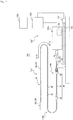
- Fig. 2 is a cross-sectional view illustrating a cross section parallel to a longitudinal direction A in a distal end portion of the diagnostic imaging catheter 110.
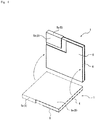
- Fig. 3 is a view illustrating the ultrasound transducer 11.
- Fig. 3 illustrates positions of electric signal lines 14 that are connected to the ultrasound transducer 11 by chain double-dashed lines, for convenience of explanation.
- Fig. 4 is a view illustrating a rear surface of a piezoelectric element 1 in the ultrasound transducer 11 illustrated in Fig. 3 .
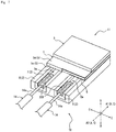
- FIG. 5 is an exploded perspective view of the ultrasound transducer 11 illustrated in Fig. 3 .
- Fig. 5 also illustrates the positions of the electric signal lines 14 that are connected to the ultrasound transducer 11 by chain double-dashed lines, for convenience of explanation.
- Fig. 5 illustrates a position of a rear surface electrode layer 5b of a first electrode 5 and a position of a second electrode 6, of the piezoelectric element 1, by dashed lines.
- Fig. 6 is a view illustrating a region where the piezoelectric element 1 and a support member 2 overlap each other in a thickness direction B, in the ultrasound transducer 11 illustrated in Fig. 3 .
- the diagnostic imaging catheter 110 is applied to Intravascular Ultrasound (abbreviated to "IVUS"). As illustrated in Fig. 1 , the diagnostic imaging catheter 110 is connected to the external device 120, and is thus driven. More specifically, the diagnostic imaging catheter 110 in the embodiment is connected to a drive unit 120a of the external device 120.
- IVUS Intravascular Ultrasound
- a side that is inserted into a living body in the longitudinal direction A of the diagnostic imaging catheter 110 is described as a "distal end side", and an opposite side thereof is described as a "proximal end side”.
- a direction from the proximal end side toward the distal end side of the diagnostic imaging catheter 110 is simply described as an "insertion direction A1" in some cases.
- a direction from the distal end side toward the proximal end side of the diagnostic imaging catheter 110 is simply described as an "extraction direction A2" in some cases.
- the diagnostic imaging catheter 110 is provided with an insertion portion 110a and an operation portion 110b.
- the insertion portion 110a is a site in the diagnostic imaging catheter 110 that is inserted into the living body and used therein.
- the operation portion 110b is a site in the diagnostic imaging catheter 110 that is operated outside the living body in the state where the insertion portion 110a is inserted into the living body.
- a portion at a further distal end side than a distal end side connector 42 is the insertion portion 110a
- a portion at a further proximal end side than the distal end side connector 42 is the operation portion 110b.
- the insertion portion 110a is provided with an ultrasound probe 10 and a sheath 20.
- the operation portion 110b is provided with an inner tube member 30 and an outer tube member 40.
- the inner tube member 30 holds an end portion at a proximal end side of the ultrasound probe 10.
- the outer tube member 40 holds an end portion at a proximal end side of the sheath 20.
- the inner tube member 30 moves in a central axis direction inside the outer tube member 40 to enable the ultrasound probe 10 to move in the longitudinal direction A inside the sheath 20.
- a drive shaft 13 and the electric signal lines 14, which are parts of the ultrasound probe 10 extend through insides of the inner tube member 30 and the outer tube member 40 over not only a region of the insertion portion 110a but also a region of the operation portion 110b, in the longitudinal direction A.
- a part of the operation portion 110b in the embodiment includes, in addition to the inner tube member 30 and the outer tube member 40, the ultrasound probe 10.
- the ultrasound probe 10 is provided with the ultrasound transducer 11, a housing 12, the drive shaft 13, and the electric signal lines 14.
- the ultrasound transducer 11 is provided with the piezoelectric element 1, the support member 2, and an acoustic matching member 3.
- the piezoelectric element 1 includes a flat piezoelectric body 4, the first electrode 5 that is laminated on at least one side of the piezoelectric body 4 in the thickness direction B, and the second electrode 6 that is laminated on at least the other side of the piezoelectric body 4 in the thickness direction B.
- a surface side of the piezoelectric element 1 one side of the piezoelectric body 4 in the thickness direction B to which at least a part of the first electrode 5 is provided.
- the other side of the piezoelectric body 4 in the thickness direction B to which at least a part of the second electrode 6 is provided is described as a "rear surface side of the piezoelectric element 1".
- the surface side of the piezoelectric element 1 is a side at which transmission and reception of ultrasound are performed.
- the rear surface side of the piezoelectric element 1 is an opposite side to the side at which transmission and reception of ultrasound is performed.
- the piezoelectric body 4 of the piezoelectric element 1 includes, for example, a piezoelectric ceramic sheet.
- the materials for the piezoelectric ceramic sheet can include piezoelectric ceramic materials such as lead titanate zirconate (PZT) and lithium niobate.
- the piezoelectric body 4 may be formed of crystal, rather than the piezoelectric ceramic material.
- the first electrode 5 and the second electrode 6 of the piezoelectric element 1 can be formed by being laminated as electrode layers respectively on the both surfaces of the piezoelectric body 4 in the thickness direction B, for example, by an ion plating method using a mask material, a vapor deposition method, and a sputtering method.
- Examples of the materials for the first electrode 5 and the second electrode 6 can include metals such as silver, chromium, copper, nickel, and gold, and a laminated body of these metals.
- the second electrode 6 in the embodiment is formed only on the rear surface side of the piezoelectric element 1.
- the first electrode 5 in the embodiment includes a folded electrode. Specifically, the first electrode 5 in the embodiment is provided with a surface electrode layer 5a, the rear surface electrode layer 5b, and an interlock conductive portion 5c.
- the surface electrode layer 5a is positioned at the surface side of the piezoelectric element 1.
- the rear surface electrode layer 5b is positioned at the rear surface side of the piezoelectric element 1.
- the interlock conductive portion 5c interlocks the surface electrode layer 5a and the rear surface electrode layer 5b to each other.
- the first electrode 5 in the embodiment is formed from the surface side over the rear surface side of the piezoelectric element 1.
- the first electrode 5 is a folded electrode, so that the rear surface electrode layer 5b of the first electrode 5, and the second electrode 6 can be disposed together on the rear surface side of the piezoelectric element 1. Accordingly, compared with a case where the first electrode and the second electrode are respectively disposed only on the different surfaces of the piezoelectric element, connection work of the electric signal lines 14 to the first electrode 5 and the second electrode 6 can be performed only at one surface side of the piezoelectric element 1.
- the piezoelectric element 1 is provided with a first portion 1a including a portion overlapping a first terminal 7 and a portion overlapping a second terminal 8 of the support member 2, which is described later, in the thickness direction B, and a second portion 1b excluding the first portion 1a, in the thickness direction B. Details of this will be described later.
- an outer shape of the piezoelectric element 1 may preferably be square as in the embodiment, rather than being rectangular. In this manner, the straightness of ultrasound can be enhanced. Accordingly, as illustrated in Fig. 6 , vertical (up-and-down direction in Fig. 6 ) and transverse (right-and-left direction in Fig. 6 ) lengths of the piezoelectric element 1 are preferably approximately the same. In addition, in a case of the compact ultrasound transducer 11 that is used inside a blood vessel, it is preferable to increase the output of ultrasound.
- the piezoelectric element 1 preferably has a square outer shape in a plan view illustrated in Fig. 6 , and an area in the second portion 1b of the piezoelectric element 1 is preferably larger than an area in the first portion 1a of the piezoelectric element 1.
- the support member 2 supports the piezoelectric element 1. Moreover, as illustrated in Figs. 3 and 5 , the support member 2 is provided with the first terminal 7 that is connected to the first electrode 5 of the piezoelectric element 1, and the second terminal 8 that is connected to the second electrode 6 of the piezoelectric element 1. Moreover, as illustrated in Fig. 3 , the first terminal 7 and the second terminal 8 are respectively provided with portions that do not overlap the piezoelectric element 1 in the thickness direction B. Such the first terminal 7 and the second terminal 8 are provided to enable an electric contact between the first electrode 5 and the second electrode 6 of the piezoelectric element 1 to be drawn out to an outer side of the piezoelectric element 1.
- the use of the first terminal 7 and the second terminal 8 mentioned above makes it easy to electrically connect the electric signal lines 14 to the piezoelectric element 1.
- the support member 2 in the embodiment supports the piezoelectric element 1 from the rear surface side of the piezoelectric element 1.
- the support member 2 is laminated on the rear surface side of the piezoelectric element 1 so as to cover the rear surface side of the piezoelectric element 1.
- Examples of the materials for the first terminal 7 and the second terminal 8 can include metals such as silver, chromium, copper, nickel, and gold, and a laminated body of these metals.
- the support member 2 in the embodiment is provided with a support main body portion 9 that is laminated on the rear surface side of the piezoelectric element 1.
- the support main body portion 9 covers at least the whole region on the rear surface side of the piezoelectric body 4 of the piezoelectric element 1.
- the support main body portion 9 in the embodiment covers the whole region on the rear surface side of the piezoelectric element 1.
- the support main body portion 9 in the embodiment extends externally further than the piezoelectric element 1 in a direction C (hereinafter, described as "in-plane direction C".) orthogonal to the thickness direction B of the piezoelectric element 1.
- the first terminal 7 and the second terminal 8 in the embodiment are supported by the support main body portion 9.
- the support main body portion 9 of the support member 2 is a sound-absorbing body including rubber and epoxy resin in which metal powder such as tungsten powder is dispersed, for example.
- the support main body portion 9 of the support member 2 can absorb ultrasound as noise from the piezoelectric element 1.
- the support member 2 in the embodiment configures a sound absorbing layer that absorbs ultrasound of the piezoelectric element 1.
- the sound absorbing layer as the support member 2 can be formed by a method in which the first terminal 7 and the second terminal 8 are disposed in advance on a sheet material forming the support main body portion 9, and this sheet material is bonded to the piezoelectric element 1, or other methods.
- the first terminal 7 and the second terminal 8 may be formed by being laminated on the sheet material forming the support main body portion 9, for example, by an ion plating method using a mask material, a vapor deposition method, and a sputtering method, and production methods thereof are not specially limited. Terminal members forming the first terminal 7 and the second terminal 8 may be joined to the support main body portion 9 by bonding or the like.
- the first terminal 7 in the embodiment is connected to the rear surface electrode layer 5b of the first electrode 5 between the piezoelectric element 1 and the support main body portion 9.
- the piezoelectric element 1 and the support member 2 in the embodiment are laminated such that the rear surface electrode layer 5b of the first electrode 5 and the first terminal 7 are opposed to each other.
- the first terminal 7 in the embodiment extends externally further than the piezoelectric element 1 in the in-plane direction C from a position between the piezoelectric element 1 and the support main body portion 9.
- the first terminal 7 is drawn out on a surface at the side of the piezoelectric element 1 in the thickness direction B of the support main body portion 9 (hereinafter, described as a "top surface of the support main body portion 9"), to a position that does not overlap the piezoelectric element 1 in the thickness direction B.
- the second terminal 8 in the embodiment is connected to the second electrode 6 between the piezoelectric element 1 and the support main body portion 9.
- the piezoelectric element 1 and the support member 2 in the embodiment is laminated such that the second electrode 6 and the second terminal 8 are opposed to each other.
- the second terminal 8 in the embodiment extends externally further than the piezoelectric element 1 in the in-plane direction C from the position between the piezoelectric element 1 and the support main body portion 9. In other words, the second terminal 8 is drawn out on the top surface of the support main body portion 9, to a position that does not overlap the piezoelectric element 1 in the thickness direction B.
- connection locations for the electric signal lines 14 do not need to be secured at the surface side of the piezoelectric element 1 on which transmission and reception of ultrasound are performed, so that it is possible to suppress breakage of a portion in the ultrasound transducer 11 at the surface side of the piezoelectric element 1 on which transmission and reception of ultrasound are performed, in the connection of the electric signal lines 14.
- first terminal 7 and the second terminal 8 are externally extended further than the piezoelectric element 1 in the in-plane direction C from the position between the piezoelectric element 1 and the support main body portion 9, so that the first terminal 7 and the second terminal 8 are in a state capable of being visually identified from the surface side of the piezoelectric element 1. Therefore, it is possible to execute the work of connecting the electric signal lines 14 to the first terminal 7 and the second terminal 8 while monitoring the connection locations by visual observation or the like. This can suppress generation of a defective piece due to a connection failure.
- the first terminal 7 and the second terminal 8 in the embodiment are drawn out from a position overlapping the piezoelectric element 1 in the thickness direction B toward a proximal end side of the longitudinal direction A, in the diagnostic imaging catheter 110. Therefore, in the first terminal 7 and the second terminal 8 in the embodiment, a portion that does not overlap the piezoelectric element 1 in the thickness direction B is provided at the proximal end side relative to the piezoelectric element 1. Accordingly, as illustrated in Fig. 2 , the first terminal 7 and the second terminal 8 in the embodiment can be easily connected to distal end portions 14a of the electric signal lines 14 that extend from a distal end of the drive shaft 13 into the housing 12.
- the first terminal 7 and the second terminal 8 in the embodiment extend to a circumferential edge in the in-plane direction C of the support member 2. More specifically, the first terminal 7 and the second terminal 8 in the embodiment extend to positions flush with an end surface in the in-plane direction C of the support main body portion 9. In this manner, it is possible to more easily connect the electric signal lines 14 to the first terminal 7 and the second terminal 8 from an outside of the ultrasound transducer 11.
- two grooves 9a are sectioned on the top surface of the support main body portion 9 opposed to the rear surface of the piezoelectric element 1.
- a transverse cross section of the groove 9a in the embodiment is a rectangular shape, and may be another transverse cross-sectional shape such as a V-character shape or a circular shape, for example.
- the first terminal 7 and the second terminal 8 in the embodiment are disposed inside the grooves 9a of the support main body portion 9.
- a top surface of the first terminal 7 and a top surface of the second terminal 8 opposing to the rear surface of the piezoelectric element 1 are disposed so as to be flush with the top surface of the support main body portion 9.
- the piezoelectric element 1 and the support member 2 are laminated on each other, so that the first electrode 5 and the second electrode 6 of the piezoelectric element 1 can be respectively come into contact with the first terminal 7 and the second terminal 8 of the support member 2, and the position stability on the support member 2 of the piezoelectric element 1 can be improved.
- the first electrode 5 and the second electrode 6 of the piezoelectric element 1 are respectively connected to the first terminal 7 and the second terminal 8 of the support member 2, using a conductive adhesive or the like.
- the top surface of the first terminal 7 and the top surface of the second terminal 8 opposing to the rear surface of the piezoelectric element 1 may be respectively disposed inside the grooves 9a without protruding from the top surface of the support main body portion 9.
- portions between the first electrode 5 and the second electrode 6 of the piezoelectric element 1 and the first terminal 7 and the second terminal 8 of the support member 2 may be filled with a conductive material such as the abovementioned conductive adhesive.
- a groove 7a that houses the electric signal line 14 is sectioned in the first terminal 7 in the embodiment.
- Such the groove 7a is sectioned in the first terminal 7, so that it is possible to connect the electric signal line 14 to the first terminal 7 in a state where the electric signal line 14 is positioned inside the groove 7a. Therefore, the efficiency of the connection work between the electric signal line 14 and the first terminal 7 is improved.
- a groove 8a that houses the electric signal line 14 is also sectioned in the second terminal 8 in the embodiment.
- Such the groove 8a is sectioned in the second terminal 8, so that it is possible to connect the electric signal line 14 to the second terminal 8 in a state where the electric signal line 14 is positioned inside the groove 8a. Therefore, the efficiency of the connection work between the electric signal line 14 and the second terminal 8 is improved.
- each of transverse cross-sectional shapes of the groove 7a and the groove 8a in the embodiment is a rectangular shape
- each groove may have another transverse cross-sectional shape such as a V-character shape or a circular shape, for example.
- the groove 7a and the groove 8a may also preferably extend to positions that are flush with the end surface in the in-plane direction C of the support main body portion 9. In this manner, the electric signal lines 14 are more easily to be positioned.
- Fig. 7 is a view illustrating an overview of a process of connecting the electric signal line 14 to the first terminal 7.
- a connection portion 14a including a conductive wire from which a coating material is removed is formed on an end portion of the electric signal line 14.
- the groove 7a of the first terminal 7 is filled with a solder paste 205.
- the groove 7a may be filled with a preliminary solder in place of the solder paste 205.
- the connection portion 14a of the electric signal line 14 is disposed on the solder paste 205 that is filled in the groove 7a of the first terminal 7.
- connection portion 14a of the electric signal line 14 may be buried in the solder paste 205 that is filled in the groove 7a.
- a preliminary solder or a solder paste may be further applied so as to sandwich the connection portion 14a with the solder paste 205.
- the solder paste 205 and the preliminary solder are heated with hot air to be melted, and the connection portion 14a is connected to the first terminal 7 inside the groove 7a. In this manner, the electric signal line 14 can be connected to the first terminal 7.
- connection method between the electric signal line 14 and the first terminal 7 is indicated herein, the same applies to a connection method between the electric signal line 14 and the second terminal 8.
- the piezoelectric element 1 is provided with the first portion 1a including the portion overlapping the first terminal 7 and the portion overlapping the second terminal 8 in the thickness direction B, and the second portion 1b excluding the first portion 1a (see Fig. 6 ).
- the whole region on the rear surface side of the second portion 1b of the piezoelectric element 1 is covered with the support main body portion 9.
- the support main body portion 9 is disposed to the whole rear surface of the second portion 1b that is a portion in which the piezoelectric element 1 mainly vibrates. Therefore, ultrasound as noise from the piezoelectric element 1 can be more reliably absorbed by the support main body portion 9.
- the acoustic matching member 3 is laminated so as to cover a part of the surface side of the piezoelectric element 1. More specifically, the acoustic matching member 3 in the embodiment is laminated so as to cover a greater part (for example, 80% or more) of the surface side of the second portion 1b of the piezoelectric element 1, but is not limited to this configuration, and may be laminated so as to cover the whole region of the surface side of the second portion 1b of the piezoelectric element 1.
- the acoustic matching member 3 may be laminated so as to cover the surface sides of both of the first portion 1a and the second portion 1b of the piezoelectric element 1, or may be laminated so as to cover the whole region of the surface side of the piezoelectric element 1.
- the acoustic matching member 3 is provided to make it possible to enhance the propagation efficiency of ultrasound to a subject.
- the acoustic matching member 3 in the embodiment configures an acoustic matching layer that enhance the propagation efficiency of ultrasound.
- the acoustic matching layer as the acoustic matching member 3 can be formed by a method of bonding a sheet material forming the acoustic matching layer to the piezoelectric element 1, a method in which a liquid acoustic integrity material forming the acoustic matching layer is applied and cured, or the like.
- the materials for the acoustic matching member 3 can include a resin material such as epoxy resin.
- the acoustic matching member 3 may include a laminated body of a resin layer including a resin material.
- the housing 12 houses the ultrasound transducer 11 an inside thereof.
- a proximal end side of the housing 12 is connected to the drive shaft 13.
- the housing 12 has a shape in which an opening portion 12a is provided to a part of a circumferential wall of a cylindrical metal pipe with both end portions in an axis direction being closed, and is formed by shaving off a metal lump, metallic powder injection molding (MIM), or the like.
- MIM metallic powder injection molding
- the housing 12 in the embodiment is provided with a distal end wall portion 12b that is positioned at a further distal end side than the above-mentioned opening portion 12a, and a proximal end wall portion 12c that is positioned at a further proximal end side than the above-mentioned opening portion 12a.
- Both end portions in the axis direction of an internal space of the housing 12 in the embodiment are respectively closed by the distal end wall portion 12b and the proximal end wall portion 12c.
- the housing 12 is closed at the distal end side and the proximal end side of the ultrasound transducer 11 to make it possible to suppress the false detection of ultrasound, and to improve the accuracy of an image diagnosis.
- the electric signal lines 14 that extend inside the drive shaft 13 penetrate through the proximal end wall portion 12c and extend into the housing 12.
- the drive shaft 13 includes a tubular body having flexibility.
- the electric signal lines 14 to be connected to the ultrasound transducer 11 are disposed.
- the drive shaft 13 includes, for example, a multilayer coil in which winding directions around the axis are different from each other. Examples of the materials for the coil can include stainless steel and a nickel-titanium (Ni-Ti) alloy. Even when the two electric signal lines 14 include a double spiral twisted pair cable, such the drive shaft 13 is employed to make it possible to enhance the shield property and reduce an influence by noise generated from the electric signal lines 14.
- the drive shaft 13 extends through insides of the inner tube member 30 and the outer tube member 40 to a hub 32, which is described later, that is positioned at a proximal end portion of the inner tube member 30. In other words, in the longitudinal direction A, the drive shaft 13 extends from a distal end portion of the insertion portion 110a to a proximal end portion of the operation portion 110b.
- the electric signal line 14 extends inside the drive shaft 13, and is electrically connected to the ultrasound transducer 11 and the external device 120.
- the electric signal line 14 extends from the distal end portion of the insertion portion 110a to the proximal end portion of the operation portion 110b.
- the plurality (two in the embodiment) of the electric signal lines 14 are provided, each of the electric signal lines 14 is connected via the first terminal 7 or the second terminal 8 of the above-mentioned support member 2 to the first electrode 5 or the second electrode 6 of the above-mentioned piezoelectric element 1.
- the plurality of the electric signal lines 14 include, for example, a twisted pair cable in which the two electric signal lines 14 are twisted to each other.
- Each of the electric signal lines 14 can be a flexible fine line member having an outer diameter larger than 0 mm and equal to or smaller than 0.1 mm and having flexibility.
- Each of the electric signal lines 14 can include, for example, a conductive wire having an outer diameter larger than 0 mm and equal to or smaller than 0.05 mm, and a coating material that is formed of an insulating material and covers the surrounding of the conductive wire.
- the connection portion 14a (see Fig. 3 , Fig. 5 ) including an exposed conductive wire from which the coating material is removed is connected to the piezoelectric element 1.
- connection portions 14a of the two electric signal lines 14 are respectively connected to the first terminal 7 and the second terminal 8 of the support member 2 using soldering, a conductive adhesive, or the like (see Fig. 7 ). Accordingly, the two electric signal lines 14 are respectively electrically connected to the first electrode 5 and the second electrode 6 of the piezoelectric element 1 via the first terminal 7 and the second terminal 8 of the support member 2. More specifically, the two electric signal lines 14 are respectively connected to the first terminal 7 and the second terminal 8 of the support member 2 at the further distal end side than the proximal end wall portion 12c of the housing 12.
- a first hollow portion 21a and a second hollow portion 21b are sectioned.
- the ultrasound probe 10 is housed in the first hollow portion 21a.
- the ultrasound probe 10 can move forwardly and rearwardly in the longitudinal direction A inside the first hollow portion 21a.
- the second hollow portion 21b allows a guide wire W to be inserted therethrough.
- a tubular guide wire insertion portion 20b that sections the second hollow portion 21b is positioned in a state of being parallel to a distal end portion of a tubular main body portion 20a that sections the first hollow portion 21a.
- the main body portion 20a and the guide wire insertion portion 20b can be formed by joining tubular members different from each other by heat-welding or the like, but the embodiment is not limited to such the formation method.
- markers 22 that are formed of an X-ray impermeable material having an X-ray contrast property are provided.
- a marker 23 having an X-ray contrast property is provided.
- the markers 22 and 23 can include, for example, a metal coil having a high X-ray impermeability, such as platinum, gold, iridium, and tungsten.
- a window portion 24 in which the permeability of ultrasound is set higher than that in other sites is formed. More specifically, the window portion 24 in the embodiment is formed in the main body portion 20a in the sheath 20.
- the window portion 24 and the guide wire insertion portion 20b of the main body portion 20a are formed of a material having flexibility, and the material is not specially limited.
- the constituent materials can include various kinds of thermoplastic elastomers such as polyethylene, styrene, polyolefin, polyurethane, polyester, polyamide, polyimide, polybutadiene, trans polyisoprene, fluorine rubber, and chlorinated polyethylene, and a polymer alloy, a polymer blend, a laminated body, and the like in which one type or two or more types among these constituent materials are combined can be also used.
- a reinforcing portion that is reinforced by a material having rigidity higher than that of the window portion 24 is included.
- the reinforcing portion is formed, for example, in such a manner that a reinforcing material in which a metal wire made of stainless steel or the like is braided in a mesh shape is disposed to a tubular member such as resin having flexibility.
- the abovementioned tubular member is formed of a material similar to that of the window portion 24.
- a hydrophilic lubricant coating layer indicating lubricity when being wet is preferably disposed to an outer surface of the sheath 20.
- a communication hole 26 that communicates an inside and an outside of the first hollow portion 21a with each other is formed. In priming, gas inside the main body portion 20a can be ejected through the communication hole 26.
- the inner tube member 30 is provided with an inner tube 31 and the hub 32
- the inner tube 31 is inserted into the outer tube member 40 so as to be capable of moving forwardly and rearwardly
- the hub 32 is provided on a proximal end side of the inner tube 31.
- the outer tube member 40 is provided with an outer tube 41, the distal end side connector 42, and a proximal end side connector 43.
- the outer tube 41 is positioned at an radially outer side of the inner tube 31, and the inner tube 31 moves forwardly and rearwardly inside the outer tube 41.
- the distal end side connector 42 connects a proximal end portion of the main body portion 20a of the sheath 20 to a distal end portion of the outer tube 41.
- the proximal end side connector 43 is provided to a proximal end portion of the outer tube 41, and is configured to receive the inner tube 31 in the outer tube 41.
- the drive shaft 13 and the electric signal lines 14 of the above-mentioned ultrasound probe 10 extend to the main body portion 20a of the sheath 20, the outer tube member 40 that is connected to the proximal end side of the main body portion 20a, and the hub 32 that is positioned at a proximal end portion of the inner tube member 30 a part of which is inserted into the outer tube member 40.
- the ultrasound probe 10 and the inner tube member 30 mentioned above are connected to each other so as to respectively and integrally move forwardly and rearwardly in the longitudinal direction A. Therefore, for example, when an operation of pushing the inner tube member 30 toward the insertion direction A1 is performed, the inner tube member 30 is pushed down into the outer tube member 40 toward the insertion direction A1. When the inner tube member 30 is pushed down into the outer tube member 40 toward the insertion direction A1, the ultrasound probe 10 connected to the inner tube member 30 moves in the insertion direction A1 inside the main body portion 20a of the sheath 20. Conversely, an operation of drawing out the inner tube member 30 toward the extraction direction A2 is performed, the inner tube member 30 is drawn out from the inside of the outer tube member 40 toward the extraction direction A2. When the inner tube member 30 is drawn out from the inside of the outer tube member 40 toward the extraction direction A2, the ultrasound probe 10 connected to the inner tube member 30 moves in the extraction direction A2 inside the main body portion 20a of the sheath 20.
- the ultrasound transducer 11 of the ultrasound probe 10 is positioned in the vicinity of a distal end of the main body portion 20a of the sheath 20.
- a stopper portion that prevents the inner tube member 30 from protruding to a further distal end side than the outer tube member 40 and prevents the outer tube member 40 from slip off to the proximal end side when the inner tube member 30 is pulled to the most proximal end side.
- the stopper portion is not specially limited as long as it has a configuration that can implement the abovementioned functions, and may include a wall portion that collides against the outer tube member 40 in the longitudinal direction A, at a prescribed position, for example.
- a connector portion that is mechanically and electrically connected to the external device 120 is provided.
- the diagnostic imaging catheter 110 is mechanically and electrically connected to the external device 120 by the connector portion that is provided to the hub 32 of the inner tube member 30.
- the electric signal lines 14 of the ultrasound probe 10 extend from the ultrasound transducer 11 to the connector portion of the hub 32, and the connector portion of the hub 32 in a state of being connected to the external device 120 electrically connects the ultrasound transducer 11 and the external device 120 to each other.
- a reception signal in the ultrasound transducer 11 is transmitted to the external device 120 via the connector portion of the hub 32, and is displayed as an image after being subjected to prescribed processing.
- the external device 120 includes a motor 121 that is a driving power source for rotating the drive shaft 13, and a motor 122 that is a driving power source for moving the drive shaft 13 in the longitudinal direction A.
- the rotation movement of the motor 122 is converted into axial movement by a ball screw 123 connected to the motor 122.
- the external device 120 in the embodiment is provided with the drive unit 120a, a controller 120b that is electrically connected to the drive unit 120a in a wired or wireless manner, and a monitor 120c that can display an image generated by the controller 120b on the basis of the reception signal received from the diagnostic imaging catheter 110.
- the motor 121, the motor 122, and the ball screw 123 in the embodiment mentioned above are provided to the drive unit 120a.
- a motion of the drive unit 120a is controlled by the controller 120b.
- the controller 120b can be configured by a processor including a CPU and a memory.
- the configuration of the external device 120 is not limited to that indicated in the embodiment, and may be, for example, a configuration of further including an external input unit such as a key board.
- the configuration of the ultrasound transducer according to the disclosure is not limited to the specific configuration specified in the above-mentioned embodiment, but various modifications and changes are possible without deviating from the scope of the claims.
- the first electrode 5 includes a folded electrode, however, a configuration in which neither the first electrode 5 nor the second electrode 6 is a folded electrode but each of the first electrode 5 and the second electrode 6 is laminated only on one surface may be employed.
- the second electrode 6 may include a folded electrode.
- connection locations for the electric signal lines 14 do not need to be secured at the surface side of the piezoelectric element 1 on which transmission and reception of ultrasound are performed, so that it is possible to suppress breakage of a portion in the ultrasound transducer 11 at the surface side of the piezoelectric element 1 on which transmission and reception of ultrasound are performed, in the connection of the electric signal lines 14.
- the configuration is not limited to the configuration of the ultrasound probe 10 indicated in the above-mentioned embodiment.
- the ultrasound probe 10 in the above-mentioned embodiment has a configuration in which only the ultrasound transducer 11 is provided as an imaging core that allows an intravascular ultrasound diagnosis, however, the configuration is not limited to this configuration but a configuration in which an optical transmitter and receiver that allows optical coherence tomography (abbreviated to "OCT") is further included may be employed, for example.
- Fig. 8 is a cross-sectional view illustrating a part of a diagnostic imaging catheter 410 that is provided with an ultrasound probe 310 including the ultrasound transducer 11 and an optical transmitter and receiver 301.
- the ultrasound probe 310 illustrated in Fig. 8 is different from the abovementioned ultrasound probe 10 in that a configuration that allows the optical coherence tomography is added.
- the optical transmitter and receiver 301 is disposed inside the housing 12.
- the optical transmitter and receiver 301 continuously transmits light (measurement light) to be transferred from an optical fiber cable as a light signal line 302 extending in the drive shaft 13, into a biological lumen, and continuously receives reflected light from a biological tissue in the biological lumen.
- the optical transmitter and receiver 301 transmits the received reflected light to the external device 120 through the light signal line 302 (see Fig. 1 ).
- the controller 120b (see Fig. 1 ) of the external device 120 causes the reflected light obtained by the measurement and the reference light obtained by separating the light from the light source to interfere with each other to generate interference light data.
- the controller 120b of the external device 120 generates a light tomographic image on the basis of the generated interference light data, and causes the monitor 120c (see Fig. 1 ) to display the light tomographic image.
- the plurality of the electric signal lines 14 are wound around the light signal line 302 in a spiral shape, and the plurality of the electric signal lines 14 extend parallel to one another. More specifically, the two electric signal lines 14 illustrated in Fig. 8 extend double helically in the surrounding of the optical fiber cable as the light signal line 302 that extends in the longitudinal direction A.
- the disclosure relates to an ultrasound transducer.
Landscapes
- Health & Medical Sciences (AREA)
- Life Sciences & Earth Sciences (AREA)
- Engineering & Computer Science (AREA)
- Heart & Thoracic Surgery (AREA)
- Molecular Biology (AREA)
- Biophysics (AREA)
- Nuclear Medicine, Radiotherapy & Molecular Imaging (AREA)
- Pathology (AREA)
- Radiology & Medical Imaging (AREA)
- Biomedical Technology (AREA)
- Veterinary Medicine (AREA)
- Medical Informatics (AREA)
- Physics & Mathematics (AREA)
- Surgery (AREA)
- Animal Behavior & Ethology (AREA)
- General Health & Medical Sciences (AREA)
- Public Health (AREA)
- Mechanical Engineering (AREA)
- Gynecology & Obstetrics (AREA)
- Ultra Sonic Daignosis Equipment (AREA)
- Transducers For Ultrasonic Waves (AREA)
Abstract
Description
- The disclosure relates to an ultrasound transducer.
- An ultrasound probe including an ultrasound transducer is used as a transmitter and receiver of ultrasound in a medical ultrasound diagnostic apparatus. Recently, an ultrasound diagnosis is performed in a state where an ultrasound probe is loaded into a catheter, and the catheter is inserted into a body.
-
PTL 1 discloses an ultrasound probe including an active transducer element having a top main surface and a bottom main surface, a top electrode that is formed on the top main surface, a bottom electrode that is formed on the bottom main surface, a conductive backing element that covers the bottom electrode, a first lead that is electrically connected to the top electrode, and a second lead that is electrically connected to the conductive backing element. - PTL 1:
JP-A-2006-198425 - A demand for downsizing an ultrasound probe to be loaded into a catheter is high in order to reduce patient burden and to enhance the insertability to a body-cavity having a smaller diameter, such as a deep blood vessel.
- The downsizing of the ultrasound probe can be implemented by downsizing an ultrasound transducer including a piezoelectric element that includes piezoelectric body and a pair of electrodes. However, when the ultrasound transducer is downsized, the piezoelectric element also becomes small. Therefore, the electrodes in the piezoelectric element also become small, so that work of connecting an electric signal line that connects the piezoelectric element to an external power supply to the electrode of the piezoelectric element becomes difficult.
- The disclosure aims to provide an ultrasound transducer having a configuration that achieves easy connection of an electric signal line to a piezoelectric element.
- An ultrasound transducer as a first aspect of the disclosure includes: a piezoelectric element; and a support member that supports the piezoelectric element, in which: the piezoelectric element includes a flat piezoelectric body, a first electrode that is laminated on at least one side of the piezoelectric body in a thickness direction, and a second electrode that is laminated on at least the other side of the piezoelectric body in the thickness direction; the support member includes a first terminal that is connected to the first electrode of the piezoelectric element, and a second terminal that is connected to the second electrode of the piezoelectric element; and the first terminal and the second terminal respectively include portions that do not overlap the piezoelectric element in the thickness direction.
- As one embodiment of the disclosure, the support member includes a support main body portion that is laminated on the piezoelectric element at the other side in the thickness direction, and extends externally further than the piezoelectric element in a direction orthogonal to the thickness direction, and the first terminal and the second terminal are supported by the support main body portion.
- As one embodiment of the disclosure, the first electrode of the piezoelectric element includes a surface electrode layer that is positioned at the one side in the thickness direction of the piezoelectric body, a rear surface electrode layer that is positioned at the other side in the thickness direction of the piezoelectric body, and an interlock conductive portion that interlocks the surface electrode layer and the rear surface electrode layer to each other.
- As one embodiment of the disclosure, the first terminal is connected to the rear surface electrode layer of the first electrode between the piezoelectric element and the support main body portion.
- As one embodiment of the disclosure, the second terminal is connected to the second electrode between the piezoelectric element and the support main body portion.
- As one embodiment of the disclosure, the piezoelectric element includes a first portion including a portion overlapping the first terminal and a portion overlapping the second terminal, in the thickness direction, and a second portion excluding the first portion, and a whole region at the other side in the thickness direction of the second portion is covered by the support main body portion.
- According to the disclosure, it is possible to provide an ultrasound transducer having a configuration that achieves easy connection of an electric signal line to a piezoelectric element.
-
- [
Fig. 1] Fig. 1 is a view illustrating a state where a diagnostic imaging catheter including an ultrasound transducer serving as one embodiment of the disclosure is connected to an external device. - [
Fig. 2] Fig. 2 is a cross-sectional view illustrating a cross section parallel to a longitudinal direction in a distal end portion of the diagnostic imaging catheter illustrated inFig. 1 . - [
Fig. 3] Fig. 3 is a view illustrating the ultrasound transducer of the diagnostic imaging catheter illustrated inFig. 1 . - [
Fig. 4] Fig. 4 is a view illustrating a rear surface of a piezoelectric element in the ultrasound transducer illustrated inFig. 3 . - [
Fig. 5] Fig. 5 is an exploded perspective view of the ultrasound transducer illustrated inFig. 3 . - [
Fig. 6] Fig. 6 is a view illustrating a region where the piezoelectric element and a support member overlap each other in a thickness direction, in the ultrasound transducer illustrated inFig. 3 . - [
Fig. 7] Fig. 7 is a view illustrating an overview of a process of connecting the electric signal line to a first terminal. - [
Fig. 8] Fig. 8 is a cross-sectional view illustrating a part of a diagnostic imaging catheter including an ultrasound transducer as one embodiment of the disclosure. - Hereinafter, an embodiment of an ultrasound transducer according to the disclosure will be described with reference to the drawings. Members and sites common in the respective drawings are denoted with the same reference numerals
- Firstly, one example of a diagnostic imaging apparatus to which an ultrasound transducer according to the disclosure can be applied will be described.
Fig. 1 is a view illustrating adiagnostic imaging apparatus 100 that is provided with anultrasound transducer 11 as one embodiment. - The
diagnostic imaging apparatus 100 is provided with adiagnostic imaging catheter 110 and anexternal device 120.Fig. 1 illustrates a state where thediagnostic imaging catheter 110 is connected to theexternal device 120.Fig. 2 is a cross-sectional view illustrating a cross section parallel to a longitudinal direction A in a distal end portion of thediagnostic imaging catheter 110.Fig. 3 is a view illustrating theultrasound transducer 11.Fig. 3 illustrates positions ofelectric signal lines 14 that are connected to theultrasound transducer 11 by chain double-dashed lines, for convenience of explanation.Fig. 4 is a view illustrating a rear surface of apiezoelectric element 1 in theultrasound transducer 11 illustrated inFig. 3 .Fig. 5 is an exploded perspective view of theultrasound transducer 11 illustrated inFig. 3 .Fig. 5 also illustrates the positions of theelectric signal lines 14 that are connected to theultrasound transducer 11 by chain double-dashed lines, for convenience of explanation. Moreover, for convenience of explanation,Fig. 5 illustrates a position of a rearsurface electrode layer 5b of afirst electrode 5 and a position of asecond electrode 6, of thepiezoelectric element 1, by dashed lines.Fig. 6 is a view illustrating a region where thepiezoelectric element 1 and asupport member 2 overlap each other in a thickness direction B, in theultrasound transducer 11 illustrated inFig. 3 . - The
diagnostic imaging catheter 110 is applied to Intravascular Ultrasound (abbreviated to "IVUS"). As illustrated inFig. 1 , thediagnostic imaging catheter 110 is connected to theexternal device 120, and is thus driven. More specifically, thediagnostic imaging catheter 110 in the embodiment is connected to adrive unit 120a of theexternal device 120. - Hereinafter, for convenience of explanation, in the
diagnostic imaging catheter 110, a side that is inserted into a living body in the longitudinal direction A of thediagnostic imaging catheter 110 is described as a "distal end side", and an opposite side thereof is described as a "proximal end side". Moreover, a direction from the proximal end side toward the distal end side of thediagnostic imaging catheter 110 is simply described as an "insertion direction A1" in some cases. Moreover, a direction from the distal end side toward the proximal end side of thediagnostic imaging catheter 110 is simply described as an "extraction direction A2" in some cases. - As illustrated in
Fig. 1 , thediagnostic imaging catheter 110 is provided with aninsertion portion 110a and anoperation portion 110b. Theinsertion portion 110a is a site in thediagnostic imaging catheter 110 that is inserted into the living body and used therein. Theoperation portion 110b is a site in thediagnostic imaging catheter 110 that is operated outside the living body in the state where theinsertion portion 110a is inserted into the living body. In thediagnostic imaging catheter 110 in the embodiment, a portion at a further distal end side than a distal end side connector 42 (seeFig. 1 ), which is described later, is theinsertion portion 110a, and a portion at a further proximal end side than the distalend side connector 42 is theoperation portion 110b. - As illustrated in
Figs. 1 and2 , theinsertion portion 110a is provided with anultrasound probe 10 and asheath 20. - As illustrated in
Fig. 1 , theoperation portion 110b is provided with aninner tube member 30 and anouter tube member 40. Theinner tube member 30 holds an end portion at a proximal end side of theultrasound probe 10. Theouter tube member 40 holds an end portion at a proximal end side of thesheath 20. Although details will be described later, theinner tube member 30 moves in a central axis direction inside theouter tube member 40 to enable theultrasound probe 10 to move in the longitudinal direction A inside thesheath 20. Moreover, although details will be described later, adrive shaft 13 and theelectric signal lines 14, which are parts of theultrasound probe 10, extend through insides of theinner tube member 30 and theouter tube member 40 over not only a region of theinsertion portion 110a but also a region of theoperation portion 110b, in the longitudinal direction A. In other words, a part of theoperation portion 110b in the embodiment includes, in addition to theinner tube member 30 and theouter tube member 40, theultrasound probe 10. - As illustrated in
Fig. 2 , theultrasound probe 10 is provided with theultrasound transducer 11, ahousing 12, thedrive shaft 13, and the electric signal lines 14. - As illustrated in
Fig. 3 , theultrasound transducer 11 is provided with thepiezoelectric element 1, thesupport member 2, and anacoustic matching member 3. Specifically, thepiezoelectric element 1 includes a flatpiezoelectric body 4, thefirst electrode 5 that is laminated on at least one side of thepiezoelectric body 4 in the thickness direction B, and thesecond electrode 6 that is laminated on at least the other side of thepiezoelectric body 4 in the thickness direction B. Hereinafter, for convenience of explanation, one side of thepiezoelectric body 4 in the thickness direction B to which at least a part of thefirst electrode 5 is provided is described as a "surface side of thepiezoelectric element 1". Moreover, for convenience of explanation, the other side of thepiezoelectric body 4 in the thickness direction B to which at least a part of thesecond electrode 6 is provided is described as a "rear surface side of thepiezoelectric element 1". The surface side of thepiezoelectric element 1 is a side at which transmission and reception of ultrasound are performed. Moreover, the rear surface side of thepiezoelectric element 1 is an opposite side to the side at which transmission and reception of ultrasound is performed. - The
piezoelectric body 4 of thepiezoelectric element 1 includes, for example, a piezoelectric ceramic sheet. Examples of the materials for the piezoelectric ceramic sheet can include piezoelectric ceramic materials such as lead titanate zirconate (PZT) and lithium niobate. Thepiezoelectric body 4 may be formed of crystal, rather than the piezoelectric ceramic material. - The
first electrode 5 and thesecond electrode 6 of thepiezoelectric element 1 can be formed by being laminated as electrode layers respectively on the both surfaces of thepiezoelectric body 4 in the thickness direction B, for example, by an ion plating method using a mask material, a vapor deposition method, and a sputtering method. Examples of the materials for thefirst electrode 5 and thesecond electrode 6 can include metals such as silver, chromium, copper, nickel, and gold, and a laminated body of these metals. - As illustrated in
Figs. 3 and4 , thesecond electrode 6 in the embodiment is formed only on the rear surface side of thepiezoelectric element 1. - In contrast, as illustrated in
Figs. 3 and4 , thefirst electrode 5 in the embodiment includes a folded electrode. Specifically, thefirst electrode 5 in the embodiment is provided with asurface electrode layer 5a, the rearsurface electrode layer 5b, and an interlockconductive portion 5c. Thesurface electrode layer 5a is positioned at the surface side of thepiezoelectric element 1. The rearsurface electrode layer 5b is positioned at the rear surface side of thepiezoelectric element 1. The interlockconductive portion 5c interlocks thesurface electrode layer 5a and the rearsurface electrode layer 5b to each other. In other words, thefirst electrode 5 in the embodiment is formed from the surface side over the rear surface side of thepiezoelectric element 1. Thefirst electrode 5 is a folded electrode, so that the rearsurface electrode layer 5b of thefirst electrode 5, and thesecond electrode 6 can be disposed together on the rear surface side of thepiezoelectric element 1. Accordingly, compared with a case where the first electrode and the second electrode are respectively disposed only on the different surfaces of the piezoelectric element, connection work of theelectric signal lines 14 to thefirst electrode 5 and thesecond electrode 6 can be performed only at one surface side of thepiezoelectric element 1. - Moreover, as illustrated in
Fig. 6 , thepiezoelectric element 1 is provided with afirst portion 1a including a portion overlapping afirst terminal 7 and a portion overlapping asecond terminal 8 of thesupport member 2, which is described later, in the thickness direction B, and asecond portion 1b excluding thefirst portion 1a, in the thickness direction B. Details of this will be described later. - Moreover, as illustrated in
Fig. 6 , in a plan view in which theultrasound transducer 11 is seen in the thickness direction B, an outer shape of thepiezoelectric element 1 may preferably be square as in the embodiment, rather than being rectangular. In this manner, the straightness of ultrasound can be enhanced. Accordingly, as illustrated inFig. 6 , vertical (up-and-down direction inFig. 6 ) and transverse (right-and-left direction inFig. 6 ) lengths of thepiezoelectric element 1 are preferably approximately the same. In addition, in a case of thecompact ultrasound transducer 11 that is used inside a blood vessel, it is preferable to increase the output of ultrasound. Therefore, it is preferable to largely secure thesecond portion 1b, which is a portion of thepiezoelectric element 1 that mainly vibrates. As in the foregoing, thepiezoelectric element 1 preferably has a square outer shape in a plan view illustrated inFig. 6 , and an area in thesecond portion 1b of thepiezoelectric element 1 is preferably larger than an area in thefirst portion 1a of thepiezoelectric element 1. - As illustrated in
Fig. 3 , thesupport member 2 supports thepiezoelectric element 1. Moreover, as illustrated inFigs. 3 and5 , thesupport member 2 is provided with thefirst terminal 7 that is connected to thefirst electrode 5 of thepiezoelectric element 1, and thesecond terminal 8 that is connected to thesecond electrode 6 of thepiezoelectric element 1. Moreover, as illustrated inFig. 3 , thefirst terminal 7 and thesecond terminal 8 are respectively provided with portions that do not overlap thepiezoelectric element 1 in the thickness direction B. Such thefirst terminal 7 and thesecond terminal 8 are provided to enable an electric contact between thefirst electrode 5 and thesecond electrode 6 of thepiezoelectric element 1 to be drawn out to an outer side of thepiezoelectric element 1. Therefore, for example, in a case where theelectric signal lines 14 are difficult to be directly connected to thefirst electrode 5 and thesecond electrode 6 of thepiezoelectric element 1, such as the downsizedpiezoelectric element 1, the use of thefirst terminal 7 and thesecond terminal 8 mentioned above makes it easy to electrically connect theelectric signal lines 14 to thepiezoelectric element 1. - As illustrated in
Fig. 3 , thesupport member 2 in the embodiment supports thepiezoelectric element 1 from the rear surface side of thepiezoelectric element 1. In other words, thesupport member 2 is laminated on the rear surface side of thepiezoelectric element 1 so as to cover the rear surface side of thepiezoelectric element 1. - Examples of the materials for the
first terminal 7 and thesecond terminal 8 can include metals such as silver, chromium, copper, nickel, and gold, and a laminated body of these metals. - More specifically, the
support member 2 in the embodiment is provided with a supportmain body portion 9 that is laminated on the rear surface side of thepiezoelectric element 1. The supportmain body portion 9 covers at least the whole region on the rear surface side of thepiezoelectric body 4 of thepiezoelectric element 1. The supportmain body portion 9 in the embodiment covers the whole region on the rear surface side of thepiezoelectric element 1. More specifically, the supportmain body portion 9 in the embodiment extends externally further than thepiezoelectric element 1 in a direction C (hereinafter, described as "in-plane direction C".) orthogonal to the thickness direction B of thepiezoelectric element 1. Thefirst terminal 7 and thesecond terminal 8 in the embodiment are supported by the supportmain body portion 9. - The support
main body portion 9 of thesupport member 2 is a sound-absorbing body including rubber and epoxy resin in which metal powder such as tungsten powder is dispersed, for example. The supportmain body portion 9 of thesupport member 2 can absorb ultrasound as noise from thepiezoelectric element 1. In other words, thesupport member 2 in the embodiment configures a sound absorbing layer that absorbs ultrasound of thepiezoelectric element 1. - The sound absorbing layer as the
support member 2 can be formed by a method in which thefirst terminal 7 and thesecond terminal 8 are disposed in advance on a sheet material forming the supportmain body portion 9, and this sheet material is bonded to thepiezoelectric element 1, or other methods. Thefirst terminal 7 and thesecond terminal 8 may be formed by being laminated on the sheet material forming the supportmain body portion 9, for example, by an ion plating method using a mask material, a vapor deposition method, and a sputtering method, and production methods thereof are not specially limited. Terminal members forming thefirst terminal 7 and thesecond terminal 8 may be joined to the supportmain body portion 9 by bonding or the like. - As illustrated in
Figs. 3 to 5 , thefirst terminal 7 in the embodiment is connected to the rearsurface electrode layer 5b of thefirst electrode 5 between thepiezoelectric element 1 and the supportmain body portion 9. In other words, thepiezoelectric element 1 and thesupport member 2 in the embodiment are laminated such that the rearsurface electrode layer 5b of thefirst electrode 5 and thefirst terminal 7 are opposed to each other. Moreover, thefirst terminal 7 in the embodiment extends externally further than thepiezoelectric element 1 in the in-plane direction C from a position between thepiezoelectric element 1 and the supportmain body portion 9. In other words, thefirst terminal 7 is drawn out on a surface at the side of thepiezoelectric element 1 in the thickness direction B of the support main body portion 9 (hereinafter, described as a "top surface of the supportmain body portion 9"), to a position that does not overlap thepiezoelectric element 1 in the thickness direction B. - As illustrated in
Figs. 3 to 5 , thesecond terminal 8 in the embodiment is connected to thesecond electrode 6 between thepiezoelectric element 1 and the supportmain body portion 9. In other words, thepiezoelectric element 1 and thesupport member 2 in the embodiment is laminated such that thesecond electrode 6 and thesecond terminal 8 are opposed to each other. Moreover, thesecond terminal 8 in the embodiment extends externally further than thepiezoelectric element 1 in the in-plane direction C from the position between thepiezoelectric element 1 and the supportmain body portion 9. In other words, thesecond terminal 8 is drawn out on the top surface of the supportmain body portion 9, to a position that does not overlap thepiezoelectric element 1 in the thickness direction B. - In this manner, the
first electrode 5 and thesecond electrode 6 of thepiezoelectric element 1 are respectively connected to thefirst terminal 7 and thesecond terminal 8 of thesupport member 2, at the rear surface side of thepiezoelectric element 1. Therefore, connection locations for theelectric signal lines 14 do not need to be secured at the surface side of thepiezoelectric element 1 on which transmission and reception of ultrasound are performed, so that it is possible to suppress breakage of a portion in theultrasound transducer 11 at the surface side of thepiezoelectric element 1 on which transmission and reception of ultrasound are performed, in the connection of the electric signal lines 14. Moreover, thefirst terminal 7 and thesecond terminal 8 are externally extended further than thepiezoelectric element 1 in the in-plane direction C from the position between thepiezoelectric element 1 and the supportmain body portion 9, so that thefirst terminal 7 and thesecond terminal 8 are in a state capable of being visually identified from the surface side of thepiezoelectric element 1. Therefore, it is possible to execute the work of connecting theelectric signal lines 14 to thefirst terminal 7 and thesecond terminal 8 while monitoring the connection locations by visual observation or the like. This can suppress generation of a defective piece due to a connection failure. - Moreover, the
first terminal 7 and thesecond terminal 8 in the embodiment are drawn out from a position overlapping thepiezoelectric element 1 in the thickness direction B toward a proximal end side of the longitudinal direction A, in thediagnostic imaging catheter 110. Therefore, in thefirst terminal 7 and thesecond terminal 8 in the embodiment, a portion that does not overlap thepiezoelectric element 1 in the thickness direction B is provided at the proximal end side relative to thepiezoelectric element 1. Accordingly, as illustrated inFig. 2 , thefirst terminal 7 and thesecond terminal 8 in the embodiment can be easily connected todistal end portions 14a of theelectric signal lines 14 that extend from a distal end of thedrive shaft 13 into thehousing 12. - In addition, as illustrated in
Fig. 3 , thefirst terminal 7 and thesecond terminal 8 in the embodiment extend to a circumferential edge in the in-plane direction C of thesupport member 2. More specifically, thefirst terminal 7 and thesecond terminal 8 in the embodiment extend to positions flush with an end surface in the in-plane direction C of the supportmain body portion 9. In this manner, it is possible to more easily connect theelectric signal lines 14 to thefirst terminal 7 and thesecond terminal 8 from an outside of theultrasound transducer 11. - Moreover, in the
support member 2 in the embodiment, twogrooves 9a are sectioned on the top surface of the supportmain body portion 9 opposed to the rear surface of thepiezoelectric element 1. A transverse cross section of thegroove 9a in the embodiment is a rectangular shape, and may be another transverse cross-sectional shape such as a V-character shape or a circular shape, for example. Thefirst terminal 7 and thesecond terminal 8 in the embodiment are disposed inside thegrooves 9a of the supportmain body portion 9. Moreover, a top surface of thefirst terminal 7 and a top surface of thesecond terminal 8 opposing to the rear surface of thepiezoelectric element 1 are disposed so as to be flush with the top surface of the supportmain body portion 9. Accordingly, thepiezoelectric element 1 and thesupport member 2 are laminated on each other, so that thefirst electrode 5 and thesecond electrode 6 of thepiezoelectric element 1 can be respectively come into contact with thefirst terminal 7 and thesecond terminal 8 of thesupport member 2, and the position stability on thesupport member 2 of thepiezoelectric element 1 can be improved. Thefirst electrode 5 and thesecond electrode 6 of thepiezoelectric element 1 are respectively connected to thefirst terminal 7 and thesecond terminal 8 of thesupport member 2, using a conductive adhesive or the like. - Note that, the top surface of the
first terminal 7 and the top surface of thesecond terminal 8 opposing to the rear surface of thepiezoelectric element 1 may be respectively disposed inside thegrooves 9a without protruding from the top surface of the supportmain body portion 9. In such a case, portions between thefirst electrode 5 and thesecond electrode 6 of thepiezoelectric element 1 and thefirst terminal 7 and thesecond terminal 8 of thesupport member 2, may be filled with a conductive material such as the abovementioned conductive adhesive. In this manner, an effect similar to the abovementioned effect by making the top surface of thefirst terminal 7, the top surface of thesecond terminal 8, and the top surface of the supportmain body portion 9 flush with one another can be obtained. - In addition, as illustrated in
Figs. 3 and5 , agroove 7a that houses theelectric signal line 14 is sectioned in thefirst terminal 7 in the embodiment. Such thegroove 7a is sectioned in thefirst terminal 7, so that it is possible to connect theelectric signal line 14 to thefirst terminal 7 in a state where theelectric signal line 14 is positioned inside thegroove 7a. Therefore, the efficiency of the connection work between theelectric signal line 14 and thefirst terminal 7 is improved. - Moreover, as illustrated in
Figs. 3 and5 , agroove 8a that houses theelectric signal line 14 is also sectioned in thesecond terminal 8 in the embodiment. Such thegroove 8a is sectioned in thesecond terminal 8, so that it is possible to connect theelectric signal line 14 to thesecond terminal 8 in a state where theelectric signal line 14 is positioned inside thegroove 8a. Therefore, the efficiency of the connection work between theelectric signal line 14 and thesecond terminal 8 is improved. - In this manner, the grooves (the
grooves first terminal 7 and thesecond terminal 8 to make it easy to connect theelectric signal lines 14 to the respective terminals (thefirst terminal 7 and thesecond terminal 8 in the embodiment). Although each of transverse cross-sectional shapes of thegroove 7a and thegroove 8a in the embodiment is a rectangular shape, each groove may have another transverse cross-sectional shape such as a V-character shape or a circular shape, for example. Moreover, thegroove 7a and thegroove 8a may also preferably extend to positions that are flush with the end surface in the in-plane direction C of the supportmain body portion 9. In this manner, theelectric signal lines 14 are more easily to be positioned. - Herein, one example of a method of connecting the
electric signal line 14 to thefirst terminal 7 will be described.Fig. 7 is a view illustrating an overview of a process of connecting theelectric signal line 14 to thefirst terminal 7. Firstly, aconnection portion 14a including a conductive wire from which a coating material is removed is formed on an end portion of theelectric signal line 14. Moreover, thegroove 7a of thefirst terminal 7 is filled with asolder paste 205. Thegroove 7a may be filled with a preliminary solder in place of thesolder paste 205. In this state, theconnection portion 14a of theelectric signal line 14 is disposed on thesolder paste 205 that is filled in thegroove 7a of thefirst terminal 7. Theconnection portion 14a of theelectric signal line 14 may be buried in thesolder paste 205 that is filled in thegroove 7a. A preliminary solder or a solder paste may be further applied so as to sandwich theconnection portion 14a with thesolder paste 205. Next, thesolder paste 205 and the preliminary solder are heated with hot air to be melted, and theconnection portion 14a is connected to thefirst terminal 7 inside thegroove 7a. In this manner, theelectric signal line 14 can be connected to thefirst terminal 7. - Although the connection method between the
electric signal line 14 and thefirst terminal 7 is indicated herein, the same applies to a connection method between theelectric signal line 14 and thesecond terminal 8. - Moreover, as described above, the
piezoelectric element 1 is provided with thefirst portion 1a including the portion overlapping thefirst terminal 7 and the portion overlapping thesecond terminal 8 in the thickness direction B, and thesecond portion 1b excluding thefirst portion 1a (seeFig. 6 ). As illustrated inFig. 6 , in the embodiment, the whole region on the rear surface side of thesecond portion 1b of thepiezoelectric element 1 is covered with the supportmain body portion 9. With such a configuration, the supportmain body portion 9 is disposed to the whole rear surface of thesecond portion 1b that is a portion in which thepiezoelectric element 1 mainly vibrates. Therefore, ultrasound as noise from thepiezoelectric element 1 can be more reliably absorbed by the supportmain body portion 9. - As illustrated in
Fig. 3 , theacoustic matching member 3 is laminated so as to cover a part of the surface side of thepiezoelectric element 1. More specifically, theacoustic matching member 3 in the embodiment is laminated so as to cover a greater part (for example, 80% or more) of the surface side of thesecond portion 1b of thepiezoelectric element 1, but is not limited to this configuration, and may be laminated so as to cover the whole region of the surface side of thesecond portion 1b of thepiezoelectric element 1. Moreover, theacoustic matching member 3 may be laminated so as to cover the surface sides of both of thefirst portion 1a and thesecond portion 1b of thepiezoelectric element 1, or may be laminated so as to cover the whole region of the surface side of thepiezoelectric element 1. - The
acoustic matching member 3 is provided to make it possible to enhance the propagation efficiency of ultrasound to a subject. In other words, theacoustic matching member 3 in the embodiment configures an acoustic matching layer that enhance the propagation efficiency of ultrasound. - The acoustic matching layer as the
acoustic matching member 3 can be formed by a method of bonding a sheet material forming the acoustic matching layer to thepiezoelectric element 1, a method in which a liquid acoustic integrity material forming the acoustic matching layer is applied and cured, or the like. Examples of the materials for theacoustic matching member 3 can include a resin material such as epoxy resin. Moreover, theacoustic matching member 3 may include a laminated body of a resin layer including a resin material. - As illustrated in
Fig. 2 , thehousing 12 houses theultrasound transducer 11 an inside thereof. A proximal end side of thehousing 12 is connected to thedrive shaft 13. Thehousing 12 has a shape in which anopening portion 12a is provided to a part of a circumferential wall of a cylindrical metal pipe with both end portions in an axis direction being closed, and is formed by shaving off a metal lump, metallic powder injection molding (MIM), or the like. - More specifically, the
housing 12 in the embodiment is provided with a distalend wall portion 12b that is positioned at a further distal end side than the above-mentionedopening portion 12a, and a proximalend wall portion 12c that is positioned at a further proximal end side than the above-mentionedopening portion 12a. Both end portions in the axis direction of an internal space of thehousing 12 in the embodiment are respectively closed by the distalend wall portion 12b and the proximalend wall portion 12c. Thehousing 12 is closed at the distal end side and the proximal end side of theultrasound transducer 11 to make it possible to suppress the false detection of ultrasound, and to improve the accuracy of an image diagnosis. As illustrated inFig. 2 , theelectric signal lines 14 that extend inside thedrive shaft 13 penetrate through the proximalend wall portion 12c and extend into thehousing 12. - The
drive shaft 13 includes a tubular body having flexibility. In an inside of thedrive shaft 13, theelectric signal lines 14 to be connected to theultrasound transducer 11 are disposed. Thedrive shaft 13 includes, for example, a multilayer coil in which winding directions around the axis are different from each other. Examples of the materials for the coil can include stainless steel and a nickel-titanium (Ni-Ti) alloy. Even when the twoelectric signal lines 14 include a double spiral twisted pair cable, such thedrive shaft 13 is employed to make it possible to enhance the shield property and reduce an influence by noise generated from the electric signal lines 14. - The
drive shaft 13 extends through insides of theinner tube member 30 and theouter tube member 40 to ahub 32, which is described later, that is positioned at a proximal end portion of theinner tube member 30. In other words, in the longitudinal direction A, thedrive shaft 13 extends from a distal end portion of theinsertion portion 110a to a proximal end portion of theoperation portion 110b. - As illustrated in
Fig. 2 , theelectric signal line 14 extends inside thedrive shaft 13, and is electrically connected to theultrasound transducer 11 and theexternal device 120. In other words, similar to thedrive shaft 13, in the longitudinal direction A, theelectric signal line 14 extends from the distal end portion of theinsertion portion 110a to the proximal end portion of theoperation portion 110b. The plurality (two in the embodiment) of theelectric signal lines 14 are provided, each of theelectric signal lines 14 is connected via thefirst terminal 7 or thesecond terminal 8 of the above-mentionedsupport member 2 to thefirst electrode 5 or thesecond electrode 6 of the above-mentionedpiezoelectric element 1. The plurality of theelectric signal lines 14 include, for example, a twisted pair cable in which the twoelectric signal lines 14 are twisted to each other. Each of theelectric signal lines 14 can be a flexible fine line member having an outer diameter larger than 0 mm and equal to or smaller than 0.1 mm and having flexibility. Each of theelectric signal lines 14 can include, for example, a conductive wire having an outer diameter larger than 0 mm and equal to or smaller than 0.05 mm, and a coating material that is formed of an insulating material and covers the surrounding of the conductive wire. In such theelectric signal line 14, theconnection portion 14a (seeFig. 3 ,Fig. 5 ) including an exposed conductive wire from which the coating material is removed is connected to thepiezoelectric element 1. - In the embodiment, the
connection portions 14a of the twoelectric signal lines 14 are respectively connected to thefirst terminal 7 and thesecond terminal 8 of thesupport member 2 using soldering, a conductive adhesive, or the like (seeFig. 7 ). Accordingly, the twoelectric signal lines 14 are respectively electrically connected to thefirst electrode 5 and thesecond electrode 6 of thepiezoelectric element 1 via thefirst terminal 7 and thesecond terminal 8 of thesupport member 2. More specifically, the twoelectric signal lines 14 are respectively connected to thefirst terminal 7 and thesecond terminal 8 of thesupport member 2 at the further distal end side than the proximalend wall portion 12c of thehousing 12. - As illustrated in
Fig. 2 , in thesheath 20, a firsthollow portion 21a and a secondhollow portion 21b are sectioned. Theultrasound probe 10 is housed in the firsthollow portion 21a. Theultrasound probe 10 can move forwardly and rearwardly in the longitudinal direction A inside the firsthollow portion 21a. The secondhollow portion 21b allows a guide wire W to be inserted therethrough. In the embodiment, a tubular guidewire insertion portion 20b that sections the secondhollow portion 21b is positioned in a state of being parallel to a distal end portion of a tubularmain body portion 20a that sections the firsthollow portion 21a. Themain body portion 20a and the guidewire insertion portion 20b can be formed by joining tubular members different from each other by heat-welding or the like, but the embodiment is not limited to such the formation method. - In the
main body portion 20a,markers 22 that are formed of an X-ray impermeable material having an X-ray contrast property are provided. Moreover, in the guidewire insertion portion 20b as well, amarker 23 having an X-ray contrast property is provided. Themarkers - In a range in which the
ultrasound transducer 11 moves in the longitudinal direction A of thesheath 20, awindow portion 24 in which the permeability of ultrasound is set higher than that in other sites is formed. More specifically, thewindow portion 24 in the embodiment is formed in themain body portion 20a in thesheath 20. - The
window portion 24 and the guidewire insertion portion 20b of themain body portion 20a are formed of a material having flexibility, and the material is not specially limited. Examples of the constituent materials can include various kinds of thermoplastic elastomers such as polyethylene, styrene, polyolefin, polyurethane, polyester, polyamide, polyimide, polybutadiene, trans polyisoprene, fluorine rubber, and chlorinated polyethylene, and a polymer alloy, a polymer blend, a laminated body, and the like in which one type or two or more types among these constituent materials are combined can be also used. - At the further proximal end side than the
window portion 24 of themain body portion 20a, a reinforcing portion that is reinforced by a material having rigidity higher than that of thewindow portion 24 is included. The reinforcing portion is formed, for example, in such a manner that a reinforcing material in which a metal wire made of stainless steel or the like is braided in a mesh shape is disposed to a tubular member such as resin having flexibility. The abovementioned tubular member is formed of a material similar to that of thewindow portion 24. - A hydrophilic lubricant coating layer indicating lubricity when being wet is preferably disposed to an outer surface of the
sheath 20. - In a distal end portion of the
main body portion 20a of thesheath 20, acommunication hole 26 that communicates an inside and an outside of the firsthollow portion 21a with each other is formed. In priming, gas inside themain body portion 20a can be ejected through thecommunication hole 26. - As illustrated in
Fig. 1 , theinner tube member 30 is provided with aninner tube 31 and thehub 32 Theinner tube 31 is inserted into theouter tube member 40 so as to be capable of moving forwardly and rearwardly Thehub 32 is provided on a proximal end side of theinner tube 31. - As illustrated in
Fig. 1 , theouter tube member 40 is provided with anouter tube 41, the distalend side connector 42, and a proximalend side connector 43. Theouter tube 41 is positioned at an radially outer side of theinner tube 31, and theinner tube 31 moves forwardly and rearwardly inside theouter tube 41. The distalend side connector 42 connects a proximal end portion of themain body portion 20a of thesheath 20 to a distal end portion of theouter tube 41. The proximalend side connector 43 is provided to a proximal end portion of theouter tube 41, and is configured to receive theinner tube 31 in theouter tube 41. - The
drive shaft 13 and theelectric signal lines 14 of the above-mentionedultrasound probe 10 extend to themain body portion 20a of thesheath 20, theouter tube member 40 that is connected to the proximal end side of themain body portion 20a, and thehub 32 that is positioned at a proximal end portion of the inner tube member 30 a part of which is inserted into theouter tube member 40. - The
ultrasound probe 10 and theinner tube member 30 mentioned above are connected to each other so as to respectively and integrally move forwardly and rearwardly in the longitudinal direction A. Therefore, for example, when an operation of pushing theinner tube member 30 toward the insertion direction A1 is performed, theinner tube member 30 is pushed down into theouter tube member 40 toward the insertion direction A1. When theinner tube member 30 is pushed down into theouter tube member 40 toward the insertion direction A1, theultrasound probe 10 connected to theinner tube member 30 moves in the insertion direction A1 inside themain body portion 20a of thesheath 20. Conversely, an operation of drawing out theinner tube member 30 toward the extraction direction A2 is performed, theinner tube member 30 is drawn out from the inside of theouter tube member 40 toward the extraction direction A2. When theinner tube member 30 is drawn out from the inside of theouter tube member 40 toward the extraction direction A2, theultrasound probe 10 connected to theinner tube member 30 moves in the extraction direction A2 inside themain body portion 20a of thesheath 20. - When the
inner tube member 30 is most pushed down in the insertion direction A1, a distal end portion of theinner tube member 30 reaches the vicinity of the distalend side connector 42 of theouter tube member 40. At this time, theultrasound transducer 11 of theultrasound probe 10 is positioned in the vicinity of a distal end of themain body portion 20a of thesheath 20. - At the distal end portion of the
inner tube member 30, a stopper portion that prevents theinner tube member 30 from protruding to a further distal end side than theouter tube member 40 and prevents theouter tube member 40 from slip off to the proximal end side when theinner tube member 30 is pulled to the most proximal end side, is provided. The stopper portion is not specially limited as long as it has a configuration that can implement the abovementioned functions, and may include a wall portion that collides against theouter tube member 40 in the longitudinal direction A, at a prescribed position, for example. - At a proximal end of the
hub 32 of theinner tube member 30, a connector portion that is mechanically and electrically connected to theexternal device 120 is provided. In other words, thediagnostic imaging catheter 110 is mechanically and electrically connected to theexternal device 120 by the connector portion that is provided to thehub 32 of theinner tube member 30. More specifically, theelectric signal lines 14 of theultrasound probe 10 extend from theultrasound transducer 11 to the connector portion of thehub 32, and the connector portion of thehub 32 in a state of being connected to theexternal device 120 electrically connects theultrasound transducer 11 and theexternal device 120 to each other. A reception signal in theultrasound transducer 11 is transmitted to theexternal device 120 via the connector portion of thehub 32, and is displayed as an image after being subjected to prescribed processing. - As illustrated in
Fig. 1 , theexternal device 120 includes amotor 121 that is a driving power source for rotating thedrive shaft 13, and amotor 122 that is a driving power source for moving thedrive shaft 13 in the longitudinal direction A. The rotation movement of themotor 122 is converted into axial movement by aball screw 123 connected to themotor 122. - More specifically, the
external device 120 in the embodiment is provided with thedrive unit 120a, acontroller 120b that is electrically connected to thedrive unit 120a in a wired or wireless manner, and amonitor 120c that can display an image generated by thecontroller 120b on the basis of the reception signal received from thediagnostic imaging catheter 110. Themotor 121, themotor 122, and theball screw 123 in the embodiment mentioned above are provided to thedrive unit 120a. A motion of thedrive unit 120a is controlled by thecontroller 120b. Thecontroller 120b can be configured by a processor including a CPU and a memory. - The configuration of the
external device 120 is not limited to that indicated in the embodiment, and may be, for example, a configuration of further including an external input unit such as a key board. - The configuration of the ultrasound transducer according to the disclosure is not limited to the specific configuration specified in the above-mentioned embodiment, but various modifications and changes are possible without deviating from the scope of the claims. In the
ultrasound transducer 11 in the embodiment, thefirst electrode 5 includes a folded electrode, however, a configuration in which neither thefirst electrode 5 nor thesecond electrode 6 is a folded electrode but each of thefirst electrode 5 and thesecond electrode 6 is laminated only on one surface may be employed. Moreover, in place of thefirst electrode 5, thesecond electrode 6 may include a folded electrode. Note that, when thefirst electrode 5 is configured as a folded electrode as in the embodiment, thefirst electrode 5 and thesecond electrode 6 of thepiezoelectric element 1 are respectively connected to thefirst terminal 7 and thesecond terminal 8 of thesupport member 2, at the rear surface side of thepiezoelectric element 1. Therefore, as described above, connection locations for theelectric signal lines 14 do not need to be secured at the surface side of thepiezoelectric element 1 on which transmission and reception of ultrasound are performed, so that it is possible to suppress breakage of a portion in theultrasound transducer 11 at the surface side of thepiezoelectric element 1 on which transmission and reception of ultrasound are performed, in the connection of the electric signal lines 14. - Moreover, also as for the ultrasound probe to which the ultrasound transducer according to the disclosure can be applied, the configuration is not limited to the configuration of the
ultrasound probe 10 indicated in the above-mentioned embodiment. Theultrasound probe 10 in the above-mentioned embodiment has a configuration in which only theultrasound transducer 11 is provided as an imaging core that allows an intravascular ultrasound diagnosis, however, the configuration is not limited to this configuration but a configuration in which an optical transmitter and receiver that allows optical coherence tomography (abbreviated to "OCT") is further included may be employed, for example.Fig. 8 is a cross-sectional view illustrating a part of adiagnostic imaging catheter 410 that is provided with anultrasound probe 310 including theultrasound transducer 11 and an optical transmitter andreceiver 301. Theultrasound probe 310 illustrated inFig. 8 is different from theabovementioned ultrasound probe 10 in that a configuration that allows the optical coherence tomography is added. - Specifically, in the
ultrasound probe 310 illustrated inFig. 8 , in addition to theultrasound transducer 11, the optical transmitter andreceiver 301 is disposed inside thehousing 12. The optical transmitter andreceiver 301 continuously transmits light (measurement light) to be transferred from an optical fiber cable as alight signal line 302 extending in thedrive shaft 13, into a biological lumen, and continuously receives reflected light from a biological tissue in the biological lumen. The optical transmitter andreceiver 301 transmits the received reflected light to theexternal device 120 through the light signal line 302 (seeFig. 1 ). Thecontroller 120b (seeFig. 1 ) of theexternal device 120 causes the reflected light obtained by the measurement and the reference light obtained by separating the light from the light source to interfere with each other to generate interference light data. Moreover, thecontroller 120b of theexternal device 120 generates a light tomographic image on the basis of the generated interference light data, and causes themonitor 120c (seeFig. 1 ) to display the light tomographic image. - As illustrated in
Fig. 8 , inside thedrive shaft 13, the plurality of theelectric signal lines 14 are wound around thelight signal line 302 in a spiral shape, and the plurality of theelectric signal lines 14 extend parallel to one another. More specifically, the twoelectric signal lines 14 illustrated inFig. 8 extend double helically in the surrounding of the optical fiber cable as thelight signal line 302 that extends in the longitudinal direction A. - The disclosure relates to an ultrasound transducer.
-
- 1: piezoelectric element
- 1a: first portion
- 1b: second portion
- 2: support member
- 3: acoustic matching member
- 4: piezoelectric body
- 5: first electrode
- 5a: surface electrode layer
- 5b: rear surface electrode layer
- 5c: interlock conductive portion
- 6: second electrode
- 7: first terminal
- 7a: groove
- 8: second terminal
- 8a: groove
- 9: support main body portion
- 9a: groove
- 10, 310: ultrasound probe
- 11: ultrasound transducer
- 12: housing
- 12a: opening portion
- 12b: distal end wall portion
- 12c: proximal end wall portion
- 13: drive shaft
- 14: electric signal line
- 14a: connection portion
- 20: sheath
- 20a: main body portion
- 20b: guide wire insertion portion
- 21a: first hollow portion
- 21b: second hollow portion
- 22, 23: marker
- 24: window portion
- 26: communication hole
- 30: inner tube member
- 31: inner tube
- 32: hub
- 40: outer tube member
- 41: outer tube
- 42: distal end side connector
- 43: proximal end side connector
- 100: diagnostic imaging apparatus
- 110, 410: diagnostic imaging catheter
- 110a: insertion portion
- 110b: operation portion
- 120: external device
- 120a: drive unit
- 120b: controller
- 120c: monitor
- 121: motor
- 122: motor
- 123: ball screw
- 205: solder paste
- 301: optical transmitter and receiver
- 302: light signal line
- A: longitudinal direction in diagnostic imaging catheter
- A1: insertion direction
- A2: extraction direction
- B: thickness direction of piezoelectric element
- C: in-plane direction (direction orthogonal to thickness direction of piezoelectric element)
- W: guide wire
Claims (6)
- An ultrasound transducer comprising: a piezoelectric element; and a support member that supports the piezoelectric element, wherein:the piezoelectric element includesa flat piezoelectric body,a first electrode that is laminated on at least one side of the piezoelectric body in a thickness direction, anda second electrode that is laminated on at least the other side of the piezoelectric body in the thickness direction;the support member includesa first terminal that is connected to the first electrode of the piezoelectric element, anda second terminal that is connected to the second electrode of the piezoelectric element; andthe first terminal and the second terminal respectively include portions that do not overlap the piezoelectric element in the thickness direction.
- The ultrasound transducer according to claim 1, whereinthe support member includes a support main body portion that is laminated on the piezoelectric element at the other side in the thickness direction, and extends externally further than the piezoelectric element in a direction orthogonal to the thickness direction, andthe first terminal and the second terminal are supported by the support main body portion.
- The ultrasound transducer according to claim 2, whereinthe first electrode of the piezoelectric element includesa surface electrode layer that is positioned at the one side in the thickness direction of the piezoelectric body,a rear surface electrode layer that is positioned at the other side in the thickness direction of the piezoelectric body, andan interlock conductive portion that interlocks the surface electrode layer and the rear surface electrode layer to each other.
- The ultrasound transducer according to claim 3, wherein the first terminal is connected to the rear surface electrode layer of the first electrode between the piezoelectric element and the support main body portion.
- The ultrasound transducer according to any one of claims 2 to 4, wherein the second terminal is connected to the second electrode between the piezoelectric element and the support main body portion.
- The ultrasound transducer according to any one of claims 2 to 5, whereinthe piezoelectric element includesa first portion including a portion overlapping the first terminal and a portion overlapping the second terminal, in the thickness direction, anda second portion excluding the first portion, anda whole region at the other side in the thickness direction of the second portion is covered by the support main body portion.
Applications Claiming Priority (2)
| Application Number | Priority Date | Filing Date | Title |
|---|---|---|---|
| JP2019058608 | 2019-03-26 | ||
| PCT/JP2020/012778 WO2020196428A1 (en) | 2019-03-26 | 2020-03-23 | Ultrasonic vibrator |
Publications (3)
| Publication Number | Publication Date |
|---|---|
| EP3932324A1 true EP3932324A1 (en) | 2022-01-05 |
| EP3932324A4 EP3932324A4 (en) | 2022-04-20 |
| EP3932324B1 EP3932324B1 (en) | 2024-11-06 |
Family
ID=72611003
Family Applications (1)
| Application Number | Title | Priority Date | Filing Date |
|---|---|---|---|
| EP20776445.7A Active EP3932324B1 (en) | 2019-03-26 | 2020-03-23 | Ultrasonic vibrator |
Country Status (5)
| Country | Link |
|---|---|
| US (1) | US12558065B2 (en) |
| EP (1) | EP3932324B1 (en) |
| JP (1) | JP7403532B2 (en) |
| CN (1) | CN113453627B (en) |
| WO (1) | WO2020196428A1 (en) |
Families Citing this family (1)
| Publication number | Priority date | Publication date | Assignee | Title |
|---|---|---|---|---|
| WO2021149205A1 (en) * | 2020-01-22 | 2021-07-29 | オリンパス株式会社 | Ultrasonic vibrator unit and ultrasonic endoscope |
Family Cites Families (19)
| Publication number | Priority date | Publication date | Assignee | Title |
|---|---|---|---|---|
| US5327895A (en) * | 1991-07-10 | 1994-07-12 | Kabushiki Kaisha Toshiba | Ultrasonic probe and ultrasonic diagnosing system using ultrasonic probe |
| US5377682A (en) * | 1991-09-05 | 1995-01-03 | Matsushita Electric Industrial Co., Ltd. | Ultrasonic probe for transmission and reception of ultrasonic wave and ultrasonic diagnostic apparatus including ultrasonic probe |
| US5503145A (en) | 1992-06-19 | 1996-04-02 | Clough; Stuart | Computer-controlling life support system and method for mixed-gas diving |
| US5503154A (en) | 1994-10-13 | 1996-04-02 | Cardiovascular Imaging Systems, Inc. | Transducer for intraluminal ultrasound imaging catheter with provision for electrical isolation of transducer from the catheter core |
| JPH08191835A (en) * | 1995-01-19 | 1996-07-30 | Toshiba Corp | Ultrasonic probe |
| EP1769854A4 (en) * | 2004-07-22 | 2016-07-13 | Olympus Corp | Ultrasonic transducer |
| ATE346548T1 (en) * | 2004-07-29 | 2006-12-15 | Fujinon Corp | ULTRASONIC ENDOSCOPE |
| JP5331483B2 (en) | 2006-11-08 | 2013-10-30 | パナソニック株式会社 | Ultrasonic probe |
| JP4999669B2 (en) | 2007-12-19 | 2012-08-15 | 上田日本無線株式会社 | Ultrasonic probe |
| US7969068B2 (en) * | 2007-12-19 | 2011-06-28 | Ueda Japan Radio Co., Ltd. | Ultrasonic transducer with a retracted portion on a side surface of the piezoelectric layer |
| JP5079485B2 (en) | 2007-12-19 | 2012-11-21 | 上田日本無線株式会社 | Ultrasonic probe and manufacturing method thereof |
| JP5225670B2 (en) | 2007-12-25 | 2013-07-03 | 上田日本無線株式会社 | Ultrasonic probe and manufacturing method thereof |
| JP5065085B2 (en) | 2008-02-27 | 2012-10-31 | テルモ株式会社 | Ultrasonic probe and manufacturing method thereof |
| EP2473111B1 (en) * | 2009-09-03 | 2016-03-16 | Koninklijke Philips N.V. | Ultrasound probe with large field of view and method for fabricating such ultrasound probe |
| CN103703793B (en) * | 2012-06-26 | 2015-02-18 | 本多电子株式会社 | Electromechanical conversion element and manufacturing method therefor |
| JP6102622B2 (en) * | 2013-08-07 | 2017-03-29 | コニカミノルタ株式会社 | Ultrasonic probe |
| JP6606866B2 (en) * | 2015-05-29 | 2019-11-20 | セイコーエプソン株式会社 | Piezoelectric device and probe, electronic apparatus and ultrasonic imaging apparatus |
| WO2018003242A1 (en) * | 2016-06-30 | 2018-01-04 | 富士フイルム株式会社 | Ultrasonic endoscope |
| JP6891506B2 (en) * | 2017-01-17 | 2021-06-18 | セイコーエプソン株式会社 | Piezoelectric elements, piezoelectric actuators, ultrasonic probes, ultrasonic devices, electronic devices, liquid injection heads, and liquid injection devices |
-
2020
- 2020-03-23 JP JP2021509403A patent/JP7403532B2/en active Active
- 2020-03-23 EP EP20776445.7A patent/EP3932324B1/en active Active
- 2020-03-23 WO PCT/JP2020/012778 patent/WO2020196428A1/en not_active Ceased
- 2020-03-23 CN CN202080014073.XA patent/CN113453627B/en active Active
-
2021
- 2021-09-24 US US17/484,809 patent/US12558065B2/en active Active
Also Published As
| Publication number | Publication date |
|---|---|
| US12558065B2 (en) | 2026-02-24 |
| EP3932324A4 (en) | 2022-04-20 |
| JP7403532B2 (en) | 2023-12-22 |
| EP3932324B1 (en) | 2024-11-06 |
| WO2020196428A1 (en) | 2020-10-01 |
| JPWO2020196428A1 (en) | 2020-10-01 |
| CN113453627A (en) | 2021-09-28 |
| US20220008039A1 (en) | 2022-01-13 |
| CN113453627B (en) | 2024-03-01 |
Similar Documents
| Publication | Publication Date | Title |
|---|---|---|
| CN103957983B (en) | Medical pipe and conduit | |
| JP6378787B2 (en) | Design and method for an intravascular catheter | |
| EP4304485B1 (en) | Catheter with rotatable image array | |
| WO2012157513A1 (en) | Medical tube, catheter, and method for producing medical tube | |
| US11596310B2 (en) | Image diagnosis catheter | |
| EP3307176B1 (en) | Interconnects for intravascular ultrasound (ivus) devices | |
| US11497466B2 (en) | Diagnostic imaging catheter | |
| US20220015740A1 (en) | Diagnostic imaging catheter | |
| EP3932324B1 (en) | Ultrasonic vibrator | |
| JP6805009B2 (en) | Diagnostic imaging catheter | |
| JP7403358B2 (en) | ultrasonic probe | |
| JP7405833B2 (en) | Ultrasonic probe manufacturing method and ultrasonic probe | |
| JP7398990B2 (en) | ultrasonic probe | |
| JP2023144742A (en) | Diagnostic imaging catheter | |
| JPH0574504U (en) | Intracorporeal ultrasound diagnostic device |
Legal Events
| Date | Code | Title | Description |
|---|---|---|---|
| STAA | Information on the status of an ep patent application or granted ep patent |
Free format text: STATUS: THE INTERNATIONAL PUBLICATION HAS BEEN MADE |
|
| PUAI | Public reference made under article 153(3) epc to a published international application that has entered the european phase |
Free format text: ORIGINAL CODE: 0009012 |
|
| STAA | Information on the status of an ep patent application or granted ep patent |
Free format text: STATUS: REQUEST FOR EXAMINATION WAS MADE |
|
| 17P | Request for examination filed |
Effective date: 20210930 |
|
| AK | Designated contracting states |
Kind code of ref document: A1 Designated state(s): AL AT BE BG CH CY CZ DE DK EE ES FI FR GB GR HR HU IE IS IT LI LT LU LV MC MK MT NL NO PL PT RO RS SE SI SK SM TR |
|
| REG | Reference to a national code |
Ref country code: DE Ref legal event code: R079 Free format text: PREVIOUS MAIN CLASS: A61B0008120000 Ipc: B06B0001060000 Ref country code: DE Ref legal event code: R079 Ref document number: 602020040907 Country of ref document: DE Free format text: PREVIOUS MAIN CLASS: A61B0008120000 Ipc: B06B0001060000 |
|
| A4 | Supplementary search report drawn up and despatched |
Effective date: 20220322 |
|
| RIC1 | Information provided on ipc code assigned before grant |
Ipc: A61B 1/313 20060101ALI20220316BHEP Ipc: A61B 8/00 20060101ALI20220316BHEP Ipc: A61B 1/00 20060101ALI20220316BHEP Ipc: A61B 8/12 20060101ALI20220316BHEP Ipc: B06B 1/06 20060101AFI20220316BHEP |
|
| DAV | Request for validation of the european patent (deleted) | ||
| DAX | Request for extension of the european patent (deleted) | ||
| GRAP | Despatch of communication of intention to grant a patent |
Free format text: ORIGINAL CODE: EPIDOSNIGR1 |
|
| STAA | Information on the status of an ep patent application or granted ep patent |
Free format text: STATUS: GRANT OF PATENT IS INTENDED |
|
| INTG | Intention to grant announced |
Effective date: 20240620 |
|
| GRAS | Grant fee paid |
Free format text: ORIGINAL CODE: EPIDOSNIGR3 |
|
| GRAA | (expected) grant |
Free format text: ORIGINAL CODE: 0009210 |
|
| STAA | Information on the status of an ep patent application or granted ep patent |
Free format text: STATUS: THE PATENT HAS BEEN GRANTED |
|
| AK | Designated contracting states |
Kind code of ref document: B1 Designated state(s): AL AT BE BG CH CY CZ DE DK EE ES FI FR GB GR HR HU IE IS IT LI LT LU LV MC MK MT NL NO PL PT RO RS SE SI SK SM TR |
|
| REG | Reference to a national code |
Ref country code: GB Ref legal event code: FG4D |
|
| REG | Reference to a national code |
Ref country code: CH Ref legal event code: EP |
|
| REG | Reference to a national code |
Ref country code: DE Ref legal event code: R096 Ref document number: 602020040907 Country of ref document: DE |
|
| REG | Reference to a national code |
Ref country code: IE Ref legal event code: FG4D |
|
| REG | Reference to a national code |
Ref country code: LT Ref legal event code: MG9D |
|
| REG | Reference to a national code |
Ref country code: NL Ref legal event code: MP Effective date: 20241106 |
|
| PG25 | Lapsed in a contracting state [announced via postgrant information from national office to epo] |
Ref country code: PT Free format text: LAPSE BECAUSE OF FAILURE TO SUBMIT A TRANSLATION OF THE DESCRIPTION OR TO PAY THE FEE WITHIN THE PRESCRIBED TIME-LIMIT Effective date: 20250306 Ref country code: HR Free format text: LAPSE BECAUSE OF FAILURE TO SUBMIT A TRANSLATION OF THE DESCRIPTION OR TO PAY THE FEE WITHIN THE PRESCRIBED TIME-LIMIT Effective date: 20241106 Ref country code: IS Free format text: LAPSE BECAUSE OF FAILURE TO SUBMIT A TRANSLATION OF THE DESCRIPTION OR TO PAY THE FEE WITHIN THE PRESCRIBED TIME-LIMIT Effective date: 20250306 |
|
| PG25 | Lapsed in a contracting state [announced via postgrant information from national office to epo] |
Ref country code: NL Free format text: LAPSE BECAUSE OF FAILURE TO SUBMIT A TRANSLATION OF THE DESCRIPTION OR TO PAY THE FEE WITHIN THE PRESCRIBED TIME-LIMIT Effective date: 20241106 Ref country code: FI Free format text: LAPSE BECAUSE OF FAILURE TO SUBMIT A TRANSLATION OF THE DESCRIPTION OR TO PAY THE FEE WITHIN THE PRESCRIBED TIME-LIMIT Effective date: 20241106 |
|
| REG | Reference to a national code |
Ref country code: AT Ref legal event code: MK05 Ref document number: 1738799 Country of ref document: AT Kind code of ref document: T Effective date: 20241106 |
|
| PG25 | Lapsed in a contracting state [announced via postgrant information from national office to epo] |
Ref country code: BG Free format text: LAPSE BECAUSE OF FAILURE TO SUBMIT A TRANSLATION OF THE DESCRIPTION OR TO PAY THE FEE WITHIN THE PRESCRIBED TIME-LIMIT Effective date: 20241106 |
|
| PG25 | Lapsed in a contracting state [announced via postgrant information from national office to epo] |
Ref country code: ES Free format text: LAPSE BECAUSE OF FAILURE TO SUBMIT A TRANSLATION OF THE DESCRIPTION OR TO PAY THE FEE WITHIN THE PRESCRIBED TIME-LIMIT Effective date: 20241106 |
|
| PG25 | Lapsed in a contracting state [announced via postgrant information from national office to epo] |
Ref country code: NO Free format text: LAPSE BECAUSE OF FAILURE TO SUBMIT A TRANSLATION OF THE DESCRIPTION OR TO PAY THE FEE WITHIN THE PRESCRIBED TIME-LIMIT Effective date: 20250206 |
|
| PG25 | Lapsed in a contracting state [announced via postgrant information from national office to epo] |
Ref country code: LV Free format text: LAPSE BECAUSE OF FAILURE TO SUBMIT A TRANSLATION OF THE DESCRIPTION OR TO PAY THE FEE WITHIN THE PRESCRIBED TIME-LIMIT Effective date: 20241106 Ref country code: GR Free format text: LAPSE BECAUSE OF FAILURE TO SUBMIT A TRANSLATION OF THE DESCRIPTION OR TO PAY THE FEE WITHIN THE PRESCRIBED TIME-LIMIT Effective date: 20250207 Ref country code: AT Free format text: LAPSE BECAUSE OF FAILURE TO SUBMIT A TRANSLATION OF THE DESCRIPTION OR TO PAY THE FEE WITHIN THE PRESCRIBED TIME-LIMIT Effective date: 20241106 |
|
| PG25 | Lapsed in a contracting state [announced via postgrant information from national office to epo] |
Ref country code: PL Free format text: LAPSE BECAUSE OF FAILURE TO SUBMIT A TRANSLATION OF THE DESCRIPTION OR TO PAY THE FEE WITHIN THE PRESCRIBED TIME-LIMIT Effective date: 20241106 |
|
| PG25 | Lapsed in a contracting state [announced via postgrant information from national office to epo] |
Ref country code: RS Free format text: LAPSE BECAUSE OF FAILURE TO SUBMIT A TRANSLATION OF THE DESCRIPTION OR TO PAY THE FEE WITHIN THE PRESCRIBED TIME-LIMIT Effective date: 20250206 |
|
| PG25 | Lapsed in a contracting state [announced via postgrant information from national office to epo] |
Ref country code: SM Free format text: LAPSE BECAUSE OF FAILURE TO SUBMIT A TRANSLATION OF THE DESCRIPTION OR TO PAY THE FEE WITHIN THE PRESCRIBED TIME-LIMIT Effective date: 20241106 |
|
| PG25 | Lapsed in a contracting state [announced via postgrant information from national office to epo] |
Ref country code: DK Free format text: LAPSE BECAUSE OF FAILURE TO SUBMIT A TRANSLATION OF THE DESCRIPTION OR TO PAY THE FEE WITHIN THE PRESCRIBED TIME-LIMIT Effective date: 20241106 |
|
| PG25 | Lapsed in a contracting state [announced via postgrant information from national office to epo] |
Ref country code: EE Free format text: LAPSE BECAUSE OF FAILURE TO SUBMIT A TRANSLATION OF THE DESCRIPTION OR TO PAY THE FEE WITHIN THE PRESCRIBED TIME-LIMIT Effective date: 20241106 |
|
| PG25 | Lapsed in a contracting state [announced via postgrant information from national office to epo] |
Ref country code: RO Free format text: LAPSE BECAUSE OF FAILURE TO SUBMIT A TRANSLATION OF THE DESCRIPTION OR TO PAY THE FEE WITHIN THE PRESCRIBED TIME-LIMIT Effective date: 20241106 |
|
| PG25 | Lapsed in a contracting state [announced via postgrant information from national office to epo] |
Ref country code: SK Free format text: LAPSE BECAUSE OF FAILURE TO SUBMIT A TRANSLATION OF THE DESCRIPTION OR TO PAY THE FEE WITHIN THE PRESCRIBED TIME-LIMIT Effective date: 20241106 |
|
| PG25 | Lapsed in a contracting state [announced via postgrant information from national office to epo] |
Ref country code: CZ Free format text: LAPSE BECAUSE OF FAILURE TO SUBMIT A TRANSLATION OF THE DESCRIPTION OR TO PAY THE FEE WITHIN THE PRESCRIBED TIME-LIMIT Effective date: 20241106 |
|
| PG25 | Lapsed in a contracting state [announced via postgrant information from national office to epo] |
Ref country code: IT Free format text: LAPSE BECAUSE OF FAILURE TO SUBMIT A TRANSLATION OF THE DESCRIPTION OR TO PAY THE FEE WITHIN THE PRESCRIBED TIME-LIMIT Effective date: 20241106 |
|
| REG | Reference to a national code |
Ref country code: DE Ref legal event code: R097 Ref document number: 602020040907 Country of ref document: DE |
|
| PG25 | Lapsed in a contracting state [announced via postgrant information from national office to epo] |
Ref country code: SE Free format text: LAPSE BECAUSE OF FAILURE TO SUBMIT A TRANSLATION OF THE DESCRIPTION OR TO PAY THE FEE WITHIN THE PRESCRIBED TIME-LIMIT Effective date: 20241106 |
|
| PLBE | No opposition filed within time limit |
Free format text: ORIGINAL CODE: 0009261 |
|
| STAA | Information on the status of an ep patent application or granted ep patent |
Free format text: STATUS: NO OPPOSITION FILED WITHIN TIME LIMIT |
|
| PG25 | Lapsed in a contracting state [announced via postgrant information from national office to epo] |
Ref country code: MC Free format text: LAPSE BECAUSE OF FAILURE TO SUBMIT A TRANSLATION OF THE DESCRIPTION OR TO PAY THE FEE WITHIN THE PRESCRIBED TIME-LIMIT Effective date: 20241106 |
|
| 26N | No opposition filed |
Effective date: 20250807 |
|
| REG | Reference to a national code |
Ref country code: CH Ref legal event code: H13 Free format text: ST27 STATUS EVENT CODE: U-0-0-H10-H13 (AS PROVIDED BY THE NATIONAL OFFICE) Effective date: 20251023 |
|
| PG25 | Lapsed in a contracting state [announced via postgrant information from national office to epo] |
Ref country code: LU Free format text: LAPSE BECAUSE OF NON-PAYMENT OF DUE FEES Effective date: 20250323 |
|
| REG | Reference to a national code |
Ref country code: BE Ref legal event code: MM Effective date: 20250331 |
|
| PG25 | Lapsed in a contracting state [announced via postgrant information from national office to epo] |
Ref country code: BE Free format text: LAPSE BECAUSE OF NON-PAYMENT OF DUE FEES Effective date: 20250331 |
|
| PG25 | Lapsed in a contracting state [announced via postgrant information from national office to epo] |
Ref country code: CH Free format text: LAPSE BECAUSE OF NON-PAYMENT OF DUE FEES Effective date: 20250331 |
|
| PG25 | Lapsed in a contracting state [announced via postgrant information from national office to epo] |
Ref country code: IE Free format text: LAPSE BECAUSE OF NON-PAYMENT OF DUE FEES Effective date: 20250323 |
|
| PGFP | Annual fee paid to national office [announced via postgrant information from national office to epo] |
Ref country code: GB Payment date: 20260202 Year of fee payment: 7 |
|
| PGFP | Annual fee paid to national office [announced via postgrant information from national office to epo] |
Ref country code: DE Payment date: 20260128 Year of fee payment: 7 |
|
| PGFP | Annual fee paid to national office [announced via postgrant information from national office to epo] |
Ref country code: FR Payment date: 20260209 Year of fee payment: 7 |