EP3932234B1 - A helmetless support and ventilation system for a surgical hood and gown and methods of making and using same - Google Patents
A helmetless support and ventilation system for a surgical hood and gown and methods of making and using same Download PDFInfo
- Publication number
- EP3932234B1 EP3932234B1 EP21178368.3A EP21178368A EP3932234B1 EP 3932234 B1 EP3932234 B1 EP 3932234B1 EP 21178368 A EP21178368 A EP 21178368A EP 3932234 B1 EP3932234 B1 EP 3932234B1
- Authority
- EP
- European Patent Office
- Prior art keywords
- surgical
- support
- module
- ventilation system
- helmetless
- Prior art date
- Legal status (The legal status is an assumption and is not a legal conclusion. Google has not performed a legal analysis and makes no representation as to the accuracy of the status listed.)
- Active
Links
Images








Classifications
-
- A—HUMAN NECESSITIES
- A41—WEARING APPAREL
- A41D—OUTERWEAR; PROTECTIVE GARMENTS; ACCESSORIES
- A41D13/00—Professional, industrial or sporting protective garments, e.g. surgeons' gowns or garments protecting against blows or punches
- A41D13/12—Surgeons' or patients' gowns or dresses
- A41D13/1209—Surgeons' gowns or dresses
- A41D13/1218—Surgeons' gowns or dresses with head or face protection
-
- A—HUMAN NECESSITIES
- A41—WEARING APPAREL
- A41D—OUTERWEAR; PROTECTIVE GARMENTS; ACCESSORIES
- A41D13/00—Professional, industrial or sporting protective garments, e.g. surgeons' gowns or garments protecting against blows or punches
- A41D13/05—Professional, industrial or sporting protective garments, e.g. surgeons' gowns or garments protecting against blows or punches protecting only a particular body part
- A41D13/11—Protective face masks, e.g. for surgical use, or for use in foul atmospheres
- A41D13/1107—Protective face masks, e.g. for surgical use, or for use in foul atmospheres characterised by their shape
- A41D13/1153—Protective face masks, e.g. for surgical use, or for use in foul atmospheres characterised by their shape with a hood
-
- A—HUMAN NECESSITIES
- A41—WEARING APPAREL
- A41D—OUTERWEAR; PROTECTIVE GARMENTS; ACCESSORIES
- A41D13/00—Professional, industrial or sporting protective garments, e.g. surgeons' gowns or garments protecting against blows or punches
- A41D13/002—Professional, industrial or sporting protective garments, e.g. surgeons' gowns or garments protecting against blows or punches with controlled internal environment
- A41D13/0025—Professional, industrial or sporting protective garments, e.g. surgeons' gowns or garments protecting against blows or punches with controlled internal environment by means of forced air circulation
-
- A—HUMAN NECESSITIES
- A41—WEARING APPAREL
- A41D—OUTERWEAR; PROTECTIVE GARMENTS; ACCESSORIES
- A41D27/00—Details of garments or of their making
- A41D27/28—Means for ventilation
-
- A—HUMAN NECESSITIES
- A61—MEDICAL OR VETERINARY SCIENCE; HYGIENE
- A61G—TRANSPORT, PERSONAL CONVEYANCES OR ACCOMMODATION SPECIALLY ADAPTED FOR PATIENTS OR DISABLED PERSONS; OPERATING TABLES OR CHAIRS; CHAIRS FOR DENTISTRY; FUNERAL DEVICES
- A61G10/00—Treatment rooms or enclosures for medical purposes
-
- A—HUMAN NECESSITIES
- A61—MEDICAL OR VETERINARY SCIENCE; HYGIENE
- A61H—PHYSICAL THERAPY APPARATUS, e.g. DEVICES FOR LOCATING OR STIMULATING REFLEX POINTS IN THE BODY; ARTIFICIAL RESPIRATION; MASSAGE; BATHING DEVICES FOR SPECIAL THERAPEUTIC OR HYGIENIC PURPOSES OR SPECIFIC PARTS OF THE BODY
- A61H33/00—Bathing devices for special therapeutic or hygienic purposes
- A61H33/14—Devices for gas baths with ozone, hydrogen, or the like
-
- A—HUMAN NECESSITIES
- A61—MEDICAL OR VETERINARY SCIENCE; HYGIENE
- A61M—DEVICES FOR INTRODUCING MEDIA INTO, OR ONTO, THE BODY; DEVICES FOR TRANSDUCING BODY MEDIA OR FOR TAKING MEDIA FROM THE BODY; DEVICES FOR PRODUCING OR ENDING SLEEP OR STUPOR
- A61M21/00—Other devices or methods to cause a change in the state of consciousness; Devices for producing or ending sleep by mechanical, optical, or acoustical means, e.g. for hypnosis
- A61M21/0094—Isolation chambers used therewith, i.e. for isolating individuals from external stimuli
-
- A—HUMAN NECESSITIES
- A62—LIFE-SAVING; FIRE-FIGHTING
- A62B—DEVICES, APPARATUS OR METHODS FOR LIFE-SAVING
- A62B31/00—Containers or portable cabins for affording breathing protection with devices for reconditioning the breathing air or for ventilating, in particular those that are suitable for invalids or small children
-
- A—HUMAN NECESSITIES
- A62—LIFE-SAVING; FIRE-FIGHTING
- A62B—DEVICES, APPARATUS OR METHODS FOR LIFE-SAVING
- A62B18/00—Breathing masks or helmets, e.g. affording protection against chemical agents or for use at high altitudes or incorporating a pump or compressor for reducing the inhalation effort
- A62B18/003—Breathing masks or helmets, e.g. affording protection against chemical agents or for use at high altitudes or incorporating a pump or compressor for reducing the inhalation effort having means for creating a fresh air curtain
-
- A—HUMAN NECESSITIES
- A62—LIFE-SAVING; FIRE-FIGHTING
- A62B—DEVICES, APPARATUS OR METHODS FOR LIFE-SAVING
- A62B18/00—Breathing masks or helmets, e.g. affording protection against chemical agents or for use at high altitudes or incorporating a pump or compressor for reducing the inhalation effort
- A62B18/006—Breathing masks or helmets, e.g. affording protection against chemical agents or for use at high altitudes or incorporating a pump or compressor for reducing the inhalation effort with pumps for forced ventilation
Definitions
- the present invention is generally related to support and ventilation systems for use with surgical hoods and gowns.
- the support and ventilation system for use with surgical hoods and gowns of the present invention utilizes a helmetless support and lightweight ventilation system used in conjunction with the helmetless support.
- the gown or toga portion is a one-piece garment designed to sterilely cover the wearer when attached to the hood.
- the ventilation system will be incorporated into a lightweight and soft "yoke" that will drape over the wearer's shoulders such that only a HEPA filter of the ventilation system extends outside of the gown or toga. There will be control switches on the ventilation system to allow the wearer to adjust the fan speed and, possibly, make other inputs.
- the helmet, the one-piece gown or toga, the hood, and the ventilation system are carried by the head, neck and shoulder areas of the wearer, after a period of time, the head, neck and shoulder areas of the wearer may begin to experience an undesirable amount of muscular fatigue or strain.
- the helmet, the one-piece gown or toga, the hood, and the ventilation system weigh around 3-5 pounds. Furthermore, it is common for a surgical procedure to last for several hours.
- the extra weight of the helmet, the one-piece gown or toga, the hood and the ventilation system can place a significant muscular strain on the head, neck, and shoulder areas of the wearer.
- having the weight on the top of the head makes for a longer lever arm to support the helmet when the head is tilted to any angle other than neutral which can also put undue stress on the head, neck, and shoulder areas of the wearer. While these and other various support systems that are used to support the one-piece gown or toga, hood and ventilation system may have been generally satisfactory, there is nevertheless a need for a new and improved helmetless support and lightweight ventilation system for use with surgical hoods and gowns.
- Prior art includes: WO 00/36940 A1 , US 2016/128396 A1 , EP 2 740 377 A2 and EP 0 791 301 A2 .
- Each of these prior art disclosures describes a prior art device.
- the purpose of the invention is achieved by the subject-matter of claim 1.
- the preferred helmetless support and lightweight ventilation system for use with surgical hoods and gowns offers the following advantages: ease of use; lightness in weight; durability; the ability to distribute the device weight along the shoulders of the wearer while
- FIGS. 1-5 there is illustrated a helmetless support system 2 for use with surgical hoods and gowns.
- the helmetless support system 2 for use with surgical hoods and gowns can be used to support the one-piece surgical gown 4 and the surgical hood 14 without the need for the wearer 6 to wear a helmet.
- one-piece surgical gown 4 and the surgical hood 14 completely and sterilely covers the head, neck, and torso of the wearer 6 when donned by the wearer 6.
- the one-piece surgical gown 4 and the surgical hood 14 includes a clear faceplate 12 ( FIG. 3 ).
- the helmetless support 2 further includes a flexible headband 52 with attached lightweight front offsets 53 in front that can be releasably attached to the faceplate 12.
- the front offsets 53 FIG. 5
- helmetless support 2 for use with surgical hoods and gowns includes, in part, surgical gown 4, wearer 6, and helmetless surgical hood and gown support 50.
- surgical gown 4 is constructed of any suitable, durable, medical grade material. It is to be further understood that the surgical gown 4 is to be constructed into a one-piece design that will completely and sterilely cover the wearer when attached to the hood 14 ( FIG. 4 ).
- helmetless surgical hood and gown support 50 includes, in part, flexible, adjustable band 52, front offsets 53, faceplate attachments 54, offset extension 57, adjustable headband 60, adjustment openings 62, faceplate attachment extensions 64, sweat band 66, band pad 67, and band adjustment device 68.
- flexible band 52 is constructed of any suitable, durable, flexible, medical grade material. The important feature of flexible band 52 being that it comfortably fits around the head of the wearer 6 but still is capable of securely holding surgical gown 4 and surgical hood 14 once the surgical gown 4 and surgical hood 14 have been attached to helmetless surgical hood and gown support 50 and then placed over the wearer, as will be discussed in greater detail later. In particular, it is important that flexible band 52 be able to securely hold hood 14 off of the head of wearer 6 and allow the air to flow around the head of wearer 6, as will be discussed in greater detail later.
- a unique aspect of the present invention is the use of front offsets 53, offset extensions 57, and faceplate attachment extensions 64.
- the front offsets 53 should extend be at least 1-3 inches outwardly away from flexible band 52 so that the front offsets 53 allow air to be circulated around the head of the wearer 6, as will be discussed in greater detail later.
- front offsets 53, offset extensions 57, and faceplate attachment extensions 64 should be constructed of any suitable, durable, lightweight, medical grade material such as plastic or the like.
- Faceplate attachments 54 can be conventionally attached to offset extension 57 and faceplate attachment extensions 64 by conventional fasteners, adhesives, or the like.
- faceplate attachments 54 are constructed of hook and loop fasteners (Velcro ® ) or magnets that will allow faceplate 12 to be easily attached to and removed from front offsets 53, as will be discussed in greater later.
- the adjustable headband 60 is the adjustable headband 60, adjustment openings 62, sweat band 66, band pad 67, and band adjustment device 68.
- the height of the adjustable headband above the head of the wearer 6 can be adjusted.
- the wearer 6 can adjust the height that hood 14 is located above the head of the wearer 6 in order to adjust the flow of air around the upper part of the wearer's head.
- the length of the adjustable headband 60 can be adjusted by selecting a desired adjustment opening 62 and conventionally locating the desired adjustment opening 62 on the adjustable headband 62.
- the circumference of the flexible band 52 can be adjusted by determining the desired flexible band 52 circumference for a particular wearer 6 and utilizing the band adjustment device 68 in order to retain the desired circumference of the flexible band 52.
- a further unique aspect of the present invention is the use of sweat band 66 and band pad 67.
- the sweat band 66 contacts the forehead of the wearer 6 in order to substantially prevent any sweat from the forehead of the wearer 6 from coming into contact with the eyes of the wearer 6.
- the band pad 67 provides a cushion for the forehead of the wearer 6 while the helmetless support system 2 rests on the head of the wearer 6.
- surgical gown 4 having surgical hood 14.
- surgical hood 14 includes a conventional clear faceplate 12 and faceplate attachments 10. It is to be understood that surgical hood 14 and faceplate 12 are to be constructed of a one-piece design.
- Faceplate attachments 10 can be conventionally attached to the side of faceplate 12 that will be closest to the wearer 6 and above the top of faceplate 12 by conventional fasteners, adhesives, or the like.
- faceplate attachments 10 are constructed of hook and loop fasteners (Velcro ® ) or magnets that will allow faceplate 12 to be easily attached to and removed from front offsets 53, as will be discussed in greater detail later. It is to be understood that the number of faceplate attachments 10 should equal the number of front offsets 53.
- faceplate attachments 10 should be spaced across the side of faceplate 12 that will be closest to the wearer 6 in order to allow the faceplate 12 to be located at a predetermined distance from the face of the wearer 6.
- FIGS. 1-5 In order to attach surgical gown 4 and surgical hood 14 to the helmetless support 50, attention is directed to FIGS. 1-5 .
- the wearer 6 conventionally dons the one-piece surgical gown or toga 4 but does not place the surgical hood 14 over the head of the wearer 6.
- the wearer 6 then attaches the flexible band 52 around the head of the wearer 6. It is to be understood that the wearer 6 may adjust the height of the helmetless support 50 and circumference of the flexible band 52, as discussed earlier. As shown in FIG.
- the wearer 6 once the wearer 6 has attached the helmetless surgical hood and gown support 50 to the head of the wearer 6, the wearer 6 conventionally attaches the faceplate attachments 10 to the faceplate attachments 54 of front offsets 53 and pulls the hood 14 over the head of the wearer 6.
- the surgical hood 14 is now securely attached to the helmetless surgical hood and gown support 50 and a portion of the hood 14 rests upon the adjustable headband 60 so that surgical gown 4 and surgical hood 14 are supported by helmetless surgical hood and gown support 50.
- the helmetless support 50 now supports the surgical hood 14 and faceplate 12 so that the wearer 6 is now completely and sterilely covered by the surgical gown 4 and surgical hood 14. Furthermore, the helmetless support 50 keeps the faceplate 12 away from the face of the wearer 6 and the hood 14 away from the top and back of the head of the wearer 6 in order to allow air to flow from the ventilation system 100 around the head of the wearer 6 ( FIG. 5 ).
- FIGS. 5-18 there is illustrated a helmetless support system 2 for use with surgical hoods and gowns including a ventilation system 100.
- the helmetless support system 2 for use with surgical hoods and gowns including a ventilation system 100 can be used to support the one-piece surgical gown 4 and the surgical hood 14 without the need for the wearer 6 to wear a helmet.
- the one-piece surgical gown 4 and the surgical hood 14 completely and sterilely cover the wearer.
- the one-piece surgical gown 4 and the surgical hood 14 includes a clear faceplate 12.
- the helmetless support system 2 for use with surgical hoods and gowns further includes ventilation system 100 such that the wearer 6 can control the fan speed once the gown 4 and hood 14 have been donned.
- a face vent module 150 is used as a "yoke" to support the ventilation system 100 on the shoulders of the wearer 6. Finally, the wearer 6 can control the output from each of the various output apertures (face vent module 15, neck vent module 350, and down tube module 400) in the ventilation system 100, as will be discussed in greater detail later.
- helmetless support 2 for use with surgical hoods and gowns having ventilation system 100 includes, in part, protective casing 120, face vent module 150, air filtration module 200, power module 250, yoke module 300, neck vent module 350, down tube module 400, air flow generation module 450, and printed circuit board (PCB) module 500.
- protective casing 120 face vent module 150
- air filtration module 200 air filtration module 200
- power module 250 power module 250
- yoke module 300 the neck vent module 350
- down tube module 400 air flow generation module 450
- PCB printed circuit board
- a unique aspect of the present invention is the location of the ventilation system with respect to the surgical gown 4 and surgical hood 14.
- the ventilation system 100 is almost completely located inside of the surgical gown 4 and surgical hood 14.
- An opening 16 is conventionally constructed in the surgical hood 14 so that only a portion of the filter module 200, preferably the air filter 202, extends outside of the surgical hood 14.
- the opening 16 is connected to the air filtration adaptor 204.
- the area around the opening 16 and the air filtration adaptor 204 is conventionally sealed using seal 18 in order to substantially prevent any contaminants from entering into the surgical hood 14 and the surgical gown 4.
- the seal 18 around the opening 16 is constructed of a thermoplastic elastomer polymeric material such as an extruded elastic polyurethane film that is flexible, exhibits high traction and sealing abilities, but with increased resistance to heat, weathering, and chemicals.
- a thermoplastic elastomer polymeric material such as an extruded elastic polyurethane film that is flexible, exhibits high traction and sealing abilities, but with increased resistance to heat, weathering, and chemicals.
- the seal 18 around the opening 16 can be used to easily remove the surgical hood 14 and surgical gown 4 from the ventilation system 100, in particular, the air filtration adaptor 204.
- a lanyard 20 ( FIG. 21 ) is located adjacent to the shoulder region of the gown 4 such that the lanyard 20 is releasably attached to the shoulder region of the gown 4, wherein the lanyard 20 may be used when self-doffing (removing) the gown 4 by the wearer 6 in order to facilitate removal of the gown 4 from the filter adaptor 204 at the interface between the opening 16 and the filter adaptor 204.
- the wearer 6 grabs lanyard handle 22 and pulls on lanyard 20. The pulling action on lanyard 20 will cause the gown 4 to be removed from the filter adaptor 204 at the interface between the opening 16 and the filter adaptor 204.
- protective casing 120 preferably, is constructed of any suitable, durable, high strength, shock resistant, UV resistant, medical grade polymeric material. It is to be understood that protective casing 120 is used to encase ventilation system 100 in order to provide protection for air filtration module 200, power module 250, neck vent module 350, down tube module 400, air flow generation module 450, and printed circuit board (PCB) module 500.
- PCB printed circuit board
- face vent module 150 includes, in part, removable face vents 152, face vent openings 154, face vent connectors 156, face vent adaptors 158, face vent air flow adjustors 160, and face vent air flow adjuster lever 162.
- face vents 152 and face vent connectors 156 are constructed as a single-piece construction and are constructed of any suitable, durable, lightweight, medical grade, washable material.
- face vent openings 154 are formed in removable face vents 152 by conventional techniques such as forming, stamping, molding, or the like.
- Face vent adaptors 158 are constructed of any suitable, durable, high strength, medical grade material and are permanently connected to protective casing 180 near face vent air flow adjustors 160 and face vent airflow adjuster levers 162. Finally, face vent air flow adjustors 160 and face vent air flow adjuster lever 162, preferably, are constructed of any suitable, durable, high strength, medical grade material.
- a unique aspect of the present invention is the use of removable face vents 152.
- removable face vents 152 are constructed in such a manner that allows the removable face vents 152 to be easily removed from the face vent adaptors 158 so that the removable face vents 152 can be cleaned, disinfected, and sanitized prior to the next usage of the helmetless support 2 for use with surgical hoods and gowns having ventilation system 100.
- the removable face vents 152 Once the removable face vents 152 have been cleaned, disinfected, and sanitized, the removable face vents 152 can be easily slid onto the face vent adaptors 158 by locating the face vent connectors 156 on the face vent adaptors 158.
- Another unique aspect of the present invention is that the angle at which the removable face vents 152 direct air towards the face of the wearer 6 can be adjusted.
- the wearer 6 can rotate the removable face vents 152 along the direction of arrows B ( FIG. 9 ) so that the air is directed either higher up on lower down on the face of the wearer 6.
- a further unique aspect of the present invention is the use of face vent air flow adjustors 160 and face vent air flow adjuster lever 162.
- the wearer 6 can adjust the amount of air flow that is being emitted out of the removable face vents 152 through the use of vent air flow adjustor 160 and face vent air flow adjuster lever 162.
- the wearer 6 can conventionally manipulate face vent air flow adjuster lever 162 so that the amount of air flow is adjusted.
- the wearer 6 may push/pull the face vent air flow adjuster lever 162 upwards which will cause the amount of air flow being emitted out of the removable face vents 152 to be reduced.
- the wearer 6 may push/pull the face vent air flow adjuster lever 162 downwards which will cause the amount of air flow being emitted out of the removable face vents 152 to be increased.
- air filtration module 200 includes, in part, air filter 202 and air filtration adaptor 204.
- air filter 202 is a HEPA (or ULPA) air filter that is located within a filter casing 206.
- filter casing 206 is constructed of any suitable, durable, high strength, medical grade material.
- air filtration adaptor 204 is conventionally formed on protective casing 120.
- air filtration module 200 can be used to filter out air borne contaminants so that they do enter into the surgical hood 14 and surgical gown 4. As discussed above, only the air filter 202 extends outside of the surgical hood 14 ( FIG. 9 ). In this manner, only air going through the air filtration module 200 will be allowed to enter into the surgical hood 14 and surgical gown 4. Also, the air filter 202 can be easily removed and replaced. For example, the wearer 6 can simply remove the air filter 202 and the filter casing 206 from the air filtration adaptor 204.
- the wearer 6 can then replace the used air filter 202 and filter casing 206 with a new air filter 202 and filter casing 206 by simply placing the new air filter 202 and filter casing 206 onto the air filtration adaptor 204. It is to be understood that the air filter 202 and filter casing 206 can be retained on the air filtration adaptor 204 by a snap fit, a threaded connection, a bayonet connection, a slidable connection or the like.
- power module 250 includes, in part, battery 25, battery doors 254, and battery lock 256.
- battery 252 is a conventional, rechargeable battery such as a lithium-ion battery or the like that is capable of providing sufficient power to air flow generation module 450 and printed circuit board (PCB) module 500 for an extended period of time such as 6-8 hours.
- battery doors 254, preferably are constructed of any suitable, durable, high strength, medical grade material.
- Battery doors 254 are conventionally connected to protective casing 120 so that battery doors 254 can swing (or pivot) open so that battery 252 can be easily installed into power module 250 or removed from power module 250.
- the wearer 6 can remove battery 252 from power module 250 by opening battery doors 254 and removing battery 252 from power module 250.
- the battery 252 can then be placed on a conventional battery charger (not shown). Once the battery 252 has been fully charged, the wearer 6 can then remove the battery charger, open the battery doors 254, and slide the battery 252 into the power module 250 so that the battery 252 is securely retained within the power module 250.
- the wearer 6 then closes the battery doors 254 so that the battery 252 is not exposed to the elements.
- a conventional locking mechanism 256 can be used to lock the battery 252 in place in the power module 250 so that the battery 252 does not inadvertently come loose while the ventilation system 100 is being operated.
- yoke module 300 includes, in part, yoke 302 and yoke connectors 304.
- yoke 302 is constructed of any suitable, durable, high strength, flexible, medical grade material.
- yoke connectors 304 are attached to the back of protective casing 120.
- yoke module 300 can be used to assist in retaining ventilation system 100 on the shoulders of the wearer 6.
- yoke 302 is removably attached to protective casing through the use of yoke connectors 304. In this manner, yoke 302 can be easily attached to and removed from protective casing 120.
- yoke 302 is flexible, yoke 302 can be adjusted so as to fit the upper torso of the wearer 6 so that ventilation system 100 will remain securely retained on the shoulders and the upper torso of the wearer 6.
- the wearer 6 can position the ventilation system with the yoke module 300 installed over his/her head and place the yoke module 300 on the upper torso of the wearer 6. The wearer 6 can then pull/push on yoke 302 while yoke 302 is connected to yoke connectors 304 so that yoke 302 firmly contacts the upper torso of the wearer 6 in order to assist in retaining the ventilation system 100 on the shoulders and upper torso of the wearer 6.
- neck vent module 350 includes, in part, neck vent 352, neck vent opening 354, and neck vent adjustment lever 356.
- neck vent 352, neck vent opening 354, and neck vent adjustment lever 356 are constructed of any suitable, durable, high strength, medical grade material.
- neck vent opening 354 is formed in neck vent 352 by conventional techniques such as forming, cutting, molding or the like.
- neck vent module 350 can be used to direct the flow of air onto the back of the neck, the upper shoulder area, and the lower back of the head of the wearer 6.
- the wearer 6 can change the direction of the air coming out of neck vent opening 354 by manipulating the neck vent adjustment lever 356 in order to change an orientation of the neck vent 352.
- the wearer 6 can move the neck vent adjustment lever 356 up or down along the direction of arrows A in order to direct the air coming out of neck vent opening 354 to the desired location on the back of the neck, the upper shoulder area, and the lower back of the head of the wearer 6.
- down tube module 400 includes, in part, down tubes 402, down tube connectors 404, down tube openings 406, and down tube air flow openings 408.
- down tubes 402 are constructed of any suitable, durable, high strength, flexible, medical grade material.
- down tube connectors 404 are constructed of any suitable, durable, high strength, rigid, medical grade material.
- down tube air flow openings 408 are formed in down tubes 402 by conventional tube opening techniques such as forming, cutting, casting or the like.
- down tubes 402 should be long enough so as to assist in providing air to the upper torso of the wearer 6, as will be described in greater detail later.
- down tube module 400 Another unique aspect of the present invention is the use of down tube module 400.
- down tube connectors 404 are conventionally retained within down tube openings 406.
- Each of the down tubes 402 are then connected at one end to a down tube connectors 404 through the use of ridges 410 on down tube connectors 404 ( FIG. 12 ) so that the down tubes are conventionally secured to the down tube connectors 404.
- the ventilation system 100 is providing air to the wearer 6
- air is also being emitted from the down tube air flow openings 408 across the upper torso of the wearer 6. In this manner, the upper torso of the wearer 6 is being cooled.
- the direction at which the air is being emitted from the down tube air flow openings 408 can be adjusted by twisted or rotating the down tubes 402.
- air flow generation module 450 includes, in part, conventional electrical motor 452, conventional impeller 454, and back flow opening 456. It is to be understood that battery 252 provides the electrical power to electrical motor 452.
- Another unique aspect of the present invention is the use of air flow generation module 450.
- the configuration of the impeller 454 causes air to be drawn through the air filter module 200 in the direction of arrow C ( FIG. 15 ).
- the air filter module 200 can be used to filter the air being drawn into the ventilation system 100.
- the back flow opening 456 is provided in order to allow air that is contained within the surgical hood 14 to also be drawn through back flow opening 456 in the direction of arrows D. In this manner, the back flow opening 456 provides for an even greater circulation of the air within the hood 14 while the ventilation system 100 is in operation.
- only a portion of the filter module 200, preferably the air filter 202 extends outside of the surgical hood 14.
- PCB Printed Circuit Board
- printed circuit board module 500 includes, in part, a conventional printed circuit board 502.
- printed circuit board 502 can be used to control the ventilation system 100.
- printed circuit board 502 can be used to control the speed at which the impeller 454 ( FIG. 15 ) rotates, thereby controlling the velocity of the air being emitted from the face vents 152, the neck vent 352, and the down tubes 402.
- the printed circuit board 502 is located in the rear of the protective casing 120 so that the printed circuit board can be located adjacent to the battery 252.
- the printed circuit board 502 is conventionally retained within the protective casing 102 by conventional fasteners (not shown).
- FIGS. 5-18 Another unique aspect of the present invention is the use of ventilation system 100.
- the configuration of the impeller 454 causes air to be drawn through the air filter module 200 in the direction of arrow C ( FIG. 15 ).
- the air filter module 200 can be used to filter the air being drawn into the ventilation system 100.
- the back flow opening 456 is provided in order to allow air that is contained within the hood 14 to also be drawn through back flow opening 456 in the direction of arrow D. In this manner, air (or other similar gases) is introduced into the inside of hood 14.
- the face vent module 150 is used as a "yoke" to support the ventilation system 100 upon the shoulders of wearer 6.
- face vents 152, neck vent 352, and down tubes 402 cause the air to go up and around the head of wearer 6 and across the torso of the wearer 6 in order to cool the head, neck, and torso areas of wearer 6 ( FIG. 5 ).
- the preferred helmetless support and lightweight ventilation system for use with surgical hoods and gowns offers the following advantages: ease of use; lightness in weight; durability; the ability to distribute the device weight along the shoulders of the wearer while maintaining full mobility and greatly reducing head and neck fatigue; adjustability of the fan speed; the ability to control the amount and direction of the output from each of the various ventilation system output apertures; the ability to provide a contiguous head/hood covering; the ability to filter the air contacting the wearer; the use of front offsets to provide for air circulation around the head and neck areas of the wearer; the ability to remove the face vents for ease of cleaning or sanitizing; the ability to provide air flow within the hood; and compactness of the device.
- these advantages of ease of use, lightness in weight, durability, the ability to distribute the device weight along the shoulders of the wearer while maintaining full mobility and greatly reducing head and neck fatigue, adjustability of the fan speed, the ability to control the amount and direction of the output from each of the various ventilation system output apertures, the ability to provide a contiguous head/hood covering, the ability to filter the air contacting the wearer, the use of front offsets to provide for air circulation around the head and neck areas of the wearer, the ability to remove the face vents for ease of cleaning or sanitizing, the ability to provide air flow within the hood, and compactness of the device are optimized to an extent that is considerably higher than heretofore achieved in prior, known support and ventilation systems for use with surgical hoods and gowns.
Landscapes
- Health & Medical Sciences (AREA)
- General Health & Medical Sciences (AREA)
- Engineering & Computer Science (AREA)
- Physical Education & Sports Medicine (AREA)
- Textile Engineering (AREA)
- Public Health (AREA)
- Veterinary Medicine (AREA)
- Animal Behavior & Ethology (AREA)
- Life Sciences & Earth Sciences (AREA)
- Pulmonology (AREA)
- Environmental & Geological Engineering (AREA)
- Emergency Management (AREA)
- Rehabilitation Therapy (AREA)
- Pain & Pain Management (AREA)
- Business, Economics & Management (AREA)
- Epidemiology (AREA)
- Physics & Mathematics (AREA)
- Acoustics & Sound (AREA)
- Psychology (AREA)
- Anesthesiology (AREA)
- Biomedical Technology (AREA)
- Heart & Thoracic Surgery (AREA)
- Hematology (AREA)
- Professional, Industrial, Or Sporting Protective Garments (AREA)
Description
- The present invention is generally related to support and ventilation systems for use with surgical hoods and gowns. The support and ventilation system for use with surgical hoods and gowns of the present invention utilizes a helmetless support and lightweight ventilation system used in conjunction with the helmetless support. The gown or toga portion is a one-piece garment designed to sterilely cover the wearer when attached to the hood. The ventilation system will be incorporated into a lightweight and soft "yoke" that will drape over the wearer's shoulders such that only a HEPA filter of the ventilation system extends outside of the gown or toga. There will be control switches on the ventilation system to allow the wearer to adjust the fan speed and, possibly, make other inputs.
- Prior to the present invention, as set forth in general terms above and more specifically below, it is known, to employ various types of support systems that are used to support the one-piece gown or toga which is designed to completely and sterilely cover the wearer when attached to the hood. Currently, a helmet is donned by the wearer and the one-piece gown or toga and the hood are conventionally attached to the helmet. Furthermore, it is known to provide a ventilation system that is also attached to the helmet or attached to the wearer.
- Due to the fact that the weight of the helmet, the one-piece gown or toga, the hood, and the ventilation system are carried by the head, neck and shoulder areas of the wearer, after a period of time, the head, neck and shoulder areas of the wearer may begin to experience an undesirable amount of muscular fatigue or strain. Typically, the helmet, the one-piece gown or toga, the hood, and the ventilation system weigh around 3-5 pounds. Furthermore, it is common for a surgical procedure to last for several hours. Clearly, if the wearer of the one-piece gown or toga, the hood, and the ventilation system is bent over for several hours while performing the surgical procedure, the extra weight of the helmet, the one-piece gown or toga, the hood and the ventilation system can place a significant muscular strain on the head, neck, and shoulder areas of the wearer. Furthermore, having the weight on the top of the head makes for a longer lever arm to support the helmet when the head is tilted to any angle other than neutral which can also put undue stress on the head, neck, and shoulder areas of the wearer. While these and other various support systems that are used to support the one-piece gown or toga, hood and ventilation system may have been generally satisfactory, there is nevertheless a need for a new and improved helmetless support and lightweight ventilation system for use with surgical hoods and gowns.
- It is a purpose of this invention to fulfill these and other needs in the art of support systems that are used to support the one-piece gown or toga, hood, and ventilation system in a manner more apparent to the skilled artisan once given the following disclosure.
Prior art includes:WO 00/36940 A1 US 2016/128396 A1 ,EP 2 740 377 A2 andEP 0 791 301 A2claim 1. - Embodiments of the present disclosure are defined by the appended claims.
- The preferred helmetless support and lightweight ventilation system for use with surgical hoods and gowns, according to various embodiments of the present invention, offers the following advantages: ease of use; lightness in weight; durability; the ability to distribute the device weight along the shoulders of the wearer while
- maintaining full mobility and greatly reducing head and neck fatigue; adjustability of the fan speed; the ability to control the amount and direction of the output from each of the various ventilation system output apertures; the ability to provide a contiguous head/hood covering; the ability to filter the air contacting the wearer; the use of front offsets to provide for air circulation around the head and neck areas of the wearer; the ability to remove the face vents for ease of cleaning or sanitizing; the ability to provide air flow within the hood; and compactness of the device. In fact, in many of the preferred embodiments, these advantages are optimized to an extent that is considerably higher than heretofore achieved in prior, known support and ventilation systems for use with surgical hoods and gowns.
- The above-mentioned features and steps of the invention and the manner of attaining them will become apparent, and the invention itself will be best understood by reference to the following description of the embodiments of the invention in conjunction with the accompanying drawings, wherein like characters represent like parts throughout the several views and in which:
-
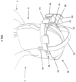
FIG. 1 is a schematic, top, isometric view of a helmetless support for use with surgical hoods and gowns, according to one embodiment of the present invention; -
FIG. 2 is a schematic, bottom, isometric view of the helmetless support for use with surgical hoods and gowns prior to the faceplate being attached to the helmetless support, according to one embodiment of the present invention; -
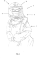
FIG. 3 is a schematic, front view of the surgical hood and gown prior to the faceplate being attached to the helmetless support, according to one embodiment of the present invention; -
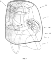
FIG. 4 is a schematic, isometric view of the helmetless support for use with surgical hoods and gowns with the faceplate being attached to the helmetless support, according to one embodiment of the present invention; -
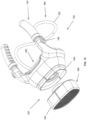
FIG. 5 is a schematic, isometric, front view of the helmetless support for use with surgical hoods and gowns with the ventilation system being installed, according to one embodiment of the present invention; -
FIG. 6 is a schematic, isometric, front view of a ventilation system for use with surgical hoods and gowns, constructed according to an embodiment of the present invention; -
FIG. 7 is a schematic, isometric, bottom view of the ventilation system for use with surgical hoods and gowns, constructed according to an embodiment of the present invention; -
FIG. 8 is a schematic, isometric, rear view of the ventilation system for use with surgical hoods and gowns, constructed according to an embodiment of the present invention; -
FIG. 8 is a schematic, rear view of the ventilation system for use with surgical hoods and gowns, constructed according to an embodiment of the present invention; -
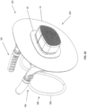
FIG. 9 is a schematic, isometric, top view of the ventilation system for use with surgical hoods and gowns with the face vents removed, constructed according to an embodiment of the present invention; -
FIG. 10 is a schematic, isometric, top view of the ventilation system for use with surgical hoods and gowns with the air filter removed, constructed according to an embodiment of the present invention; -
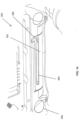
FIG. 11 is a schematic, side view of the ventilation system for use with surgical hoods and gowns illustrating the adjustable face vent air flow levers, constructed according to an embodiment of the present invention; -
FIG. 12 is a schematic, rear view of the ventilation system for use with surgical hoods and gowns illustrating the down tube adaptors, constructed according to an embodiment of the present invention; -
FIG. 13 is a schematic, isometric, rear view of the ventilation system for use with surgical hoods and gowns with the down tubes attached, constructed according to an embodiment of the present invention; -
FIG. 14 is a schematic, rear view of the ventilation system for use with surgical hoods and gowns illustrating the adjustable neck vent, constructed according to an embodiment of the present invention; -
FIG. 15 is a cut-away view, taken along lines 15-15 ofFIG. 11 of the ventilation system for use with surgical hoods and gowns illustrating the adjustable face vent air flow levers, constructed according to an embodiment of the present invention; -
FIG. 16 is an isometric, top view of the ventilation system for use with surgical hoods and gowns with a portion of the protective casing removed, constructed according to an embodiment of the present invention; -
FIG. 17 is an isometric, back view of the ventilation system for use with surgical hoods and gowns with the back cover removed illustrating the power module, constructed according to an embodiment of the present invention; -
FIG. 18 is an isometric, back view of the ventilation system for use with surgical hoods and gowns with the back cover removed illustrating the printed circuit board (PCB) module, constructed according to an embodiment of the present invention; -
FIG. 19 is a schematic, isometric, front view of a ventilation system for use with surgical hoods and gowns showing the surgical gown being attached to the ventilation system, constructed according to an embodiment of the present invention; -
FIG. 20 is a schematic, isometric, rear view of a ventilation system for use with surgical hoods and gowns showing the surgical gown being attached to the ventilation system, constructed according to an embodiment of the present invention; and -
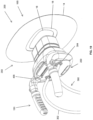
FIG. 21 is a schematic, isometric, front view of a ventilation system for use with surgical hoods and gowns showing the lanyard being attached to the surgical hood, constructed according to an embodiment of the present invention. - Referring now to
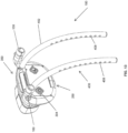
FIGS. 1-5 , there is illustrated ahelmetless support system 2 for use with surgical hoods and gowns. Thehelmetless support system 2 for use with surgical hoods and gowns can be used to support the one-piecesurgical gown 4 and thesurgical hood 14 without the need for thewearer 6 to wear a helmet. In this manner, one-piecesurgical gown 4 and thesurgical hood 14 completely and sterilely covers the head, neck, and torso of thewearer 6 when donned by thewearer 6. Also, the one-piecesurgical gown 4 and thesurgical hood 14 includes a clear faceplate 12 (FIG. 3 ). Thehelmetless support 2 further includes aflexible headband 52 with attachedlightweight front offsets 53 in front that can be releasably attached to thefaceplate 12. Furthermore, the front offsets 53 (FIG. 5 ) are used to provide for air circulation around head of thewearer 6. - As shown in
FIGS. 1 and2 ,helmetless support 2 for use with surgical hoods and gowns includes, in part,surgical gown 4,wearer 6, and helmetless surgical hood andgown support 50. It is to be understood thatsurgical gown 4 is constructed of any suitable, durable, medical grade material. It is to be further understood that thesurgical gown 4 is to be constructed into a one-piece design that will completely and sterilely cover the wearer when attached to the hood 14 (FIG. 4 ). - With respect to helmetless surgical hood and
gown support 50, helmetless surgical hood andgown support 50 includes, in part, flexible,adjustable band 52,front offsets 53,faceplate attachments 54,offset extension 57,adjustable headband 60,adjustment openings 62,faceplate attachment extensions 64,sweat band 66,band pad 67, andband adjustment device 68. Preferably,flexible band 52 is constructed of any suitable, durable, flexible, medical grade material. The important feature offlexible band 52 being that it comfortably fits around the head of thewearer 6 but still is capable of securely holdingsurgical gown 4 andsurgical hood 14 once thesurgical gown 4 andsurgical hood 14 have been attached to helmetless surgical hood andgown support 50 and then placed over the wearer, as will be discussed in greater detail later. In particular, it is important thatflexible band 52 be able to securely holdhood 14 off of the head ofwearer 6 and allow the air to flow around the head ofwearer 6, as will be discussed in greater detail later. - A unique aspect of the present invention is the use of
front offsets 53,offset extensions 57, andfaceplate attachment extensions 64. Preferably, there are at least two (2)front offsets 53 located along a perimeter on the front offlexible band 52 that hold thefaceplate 12 ofsurgical hood 14 away from the face ofwearer 6. Preferably, the front offsets 53 should extend be at least 1-3 inches outwardly away fromflexible band 52 so that thefront offsets 53 allow air to be circulated around the head of thewearer 6, as will be discussed in greater detail later. Preferably, front offsets 53, offsetextensions 57, andfaceplate attachment extensions 64 should be constructed of any suitable, durable, lightweight, medical grade material such as plastic or the like. - Another unique aspect of the present invention is
faceplate attachments 54.Faceplate attachments 54 can be conventionally attached to offsetextension 57 andfaceplate attachment extensions 64 by conventional fasteners, adhesives, or the like. Preferably,faceplate attachments 54 are constructed of hook and loop fasteners (Velcro®) or magnets that will allowfaceplate 12 to be easily attached to and removed fromfront offsets 53, as will be discussed in greater later. - With respect to
FIGS. 1 and2 , another unique aspect of the present invention is theadjustable headband 60,adjustment openings 62,sweat band 66,band pad 67, andband adjustment device 68. In particular, the height of the adjustable headband above the head of thewearer 6 can be adjusted. In this manner, thewearer 6 can adjust the height thathood 14 is located above the head of thewearer 6 in order to adjust the flow of air around the upper part of the wearer's head. For example, the length of theadjustable headband 60 can be adjusted by selecting a desiredadjustment opening 62 and conventionally locating the desired adjustment opening 62 on theadjustable headband 62. Furthermore, the circumference of theflexible band 52 can be adjusted by determining the desiredflexible band 52 circumference for aparticular wearer 6 and utilizing theband adjustment device 68 in order to retain the desired circumference of theflexible band 52. - A further unique aspect of the present invention is the use of
sweat band 66 andband pad 67. In particular, when thewearer 6 dons thehelmetless support system 2 for use with surgical hoods and gowns, thesweat band 66 contacts the forehead of thewearer 6 in order to substantially prevent any sweat from the forehead of thewearer 6 from coming into contact with the eyes of thewearer 6. Also, theband pad 67 provides a cushion for the forehead of thewearer 6 while thehelmetless support system 2 rests on the head of thewearer 6. - Regarding
FIG. 3 , there is shownsurgical gown 4 havingsurgical hood 14. As shown inFIG. 3 ,surgical hood 14 includes a conventionalclear faceplate 12 andfaceplate attachments 10. It is to be understood thatsurgical hood 14 andfaceplate 12 are to be constructed of a one-piece design. - A further unique aspect of the present invention is the use of
faceplate attachments 10.Faceplate attachments 10 can be conventionally attached to the side offaceplate 12 that will be closest to thewearer 6 and above the top offaceplate 12 by conventional fasteners, adhesives, or the like. Preferably,faceplate attachments 10 are constructed of hook and loop fasteners (Velcro®) or magnets that will allowfaceplate 12 to be easily attached to and removed fromfront offsets 53, as will be discussed in greater detail later. It is to be understood that the number offaceplate attachments 10 should equal the number of front offsets 53. Furthermore,faceplate attachments 10 should be spaced across the side offaceplate 12 that will be closest to thewearer 6 in order to allow thefaceplate 12 to be located at a predetermined distance from the face of thewearer 6. - In order to attach
surgical gown 4 andsurgical hood 14 to thehelmetless support 50, attention is directed toFIGS. 1-5 . Thewearer 6 conventionally dons the one-piece surgical gown ortoga 4 but does not place thesurgical hood 14 over the head of thewearer 6. Thewearer 6 then attaches theflexible band 52 around the head of thewearer 6. It is to be understood that thewearer 6 may adjust the height of thehelmetless support 50 and circumference of theflexible band 52, as discussed earlier. As shown inFIG. 4 , once thewearer 6 has attached the helmetless surgical hood andgown support 50 to the head of thewearer 6, thewearer 6 conventionally attaches thefaceplate attachments 10 to thefaceplate attachments 54 of front offsets 53 and pulls thehood 14 over the head of thewearer 6. In this manner, thesurgical hood 14 is now securely attached to the helmetless surgical hood andgown support 50 and a portion of thehood 14 rests upon theadjustable headband 60 so thatsurgical gown 4 andsurgical hood 14 are supported by helmetless surgical hood andgown support 50. - As shown in
FIGS. 1-5 , surgical hood14 has now been placed completely over the head ofwearer 6. In this manner, thehelmetless support 50 now supports thesurgical hood 14 andfaceplate 12 so that thewearer 6 is now completely and sterilely covered by thesurgical gown 4 andsurgical hood 14. Furthermore, thehelmetless support 50 keeps thefaceplate 12 away from the face of thewearer 6 and thehood 14 away from the top and back of the head of thewearer 6 in order to allow air to flow from theventilation system 100 around the head of the wearer 6 (FIG. 5 ). - Referring now to
FIGS. 5-18 , there is illustrated ahelmetless support system 2 for use with surgical hoods and gowns including aventilation system 100. Thehelmetless support system 2 for use with surgical hoods and gowns including aventilation system 100 can be used to support the one-piecesurgical gown 4 and thesurgical hood 14 without the need for thewearer 6 to wear a helmet. In this manner, the one-piecesurgical gown 4 and thesurgical hood 14 completely and sterilely cover the wearer. Also, the one-piecesurgical gown 4 and thesurgical hood 14 includes aclear faceplate 12. Thehelmetless support system 2 for use with surgical hoods and gowns further includesventilation system 100 such that thewearer 6 can control the fan speed once thegown 4 andhood 14 have been donned. Aface vent module 150 is used as a "yoke" to support theventilation system 100 on the shoulders of thewearer 6. Finally, thewearer 6 can control the output from each of the various output apertures (face vent module 15,neck vent module 350, and down tube module 400) in theventilation system 100, as will be discussed in greater detail later. - As shown in
FIGS. 9-12 ,helmetless support 2 for use with surgical hoods and gowns havingventilation system 100 includes, in part,protective casing 120,face vent module 150,air filtration module 200,power module 250,yoke module 300,neck vent module 350,down tube module 400, airflow generation module 450, and printed circuit board (PCB)module 500. - A unique aspect of the present invention is the location of the ventilation system with respect to the
surgical gown 4 andsurgical hood 14. As shown inFIGS. 19 and20 , in another embodiment of the present invention, theventilation system 100 is almost completely located inside of thesurgical gown 4 andsurgical hood 14. Anopening 16 is conventionally constructed in thesurgical hood 14 so that only a portion of thefilter module 200, preferably theair filter 202, extends outside of thesurgical hood 14. In particular, theopening 16 is connected to theair filtration adaptor 204. Furthermore, the area around theopening 16 and theair filtration adaptor 204 is conventionally sealed usingseal 18 in order to substantially prevent any contaminants from entering into thesurgical hood 14 and thesurgical gown 4. Preferably, theseal 18 around theopening 16 is constructed of a thermoplastic elastomer polymeric material such as an extruded elastic polyurethane film that is flexible, exhibits high traction and sealing abilities, but with increased resistance to heat, weathering, and chemicals. In this manner, theseal 18 around theopening 16 can be used to easily remove thesurgical hood 14 andsurgical gown 4 from theventilation system 100, in particular, theair filtration adaptor 204. - In another unique aspect of the present invention, as shown in
FIG. 21 , in another embodiment of the present invention, it is to be understood that a lanyard 20 (FIG. 21 ) is located adjacent to the shoulder region of thegown 4 such that thelanyard 20 is releasably attached to the shoulder region of thegown 4, wherein thelanyard 20 may be used when self-doffing (removing) thegown 4 by thewearer 6 in order to facilitate removal of thegown 4 from thefilter adaptor 204 at the interface between theopening 16 and thefilter adaptor 204. In particular, thewearer 6 grabs lanyard handle 22 and pulls onlanyard 20. The pulling action onlanyard 20 will cause thegown 4 to be removed from thefilter adaptor 204 at the interface between theopening 16 and thefilter adaptor 204. - With respect to
protective casing 120,protective casing 120, preferably, is constructed of any suitable, durable, high strength, shock resistant, UV resistant, medical grade polymeric material. It is to be understood thatprotective casing 120 is used to encaseventilation system 100 in order to provide protection forair filtration module 200,power module 250,neck vent module 350,down tube module 400, airflow generation module 450, and printed circuit board (PCB)module 500. - Regarding
face vent module 150, as shown inFIGS. 5-11 ,face vent module 150, includes, in part, removable face vents 152,face vent openings 154,face vent connectors 156,face vent adaptors 158, face ventair flow adjustors 160, and face vent airflow adjuster lever 162. Preferably, face vents 152 and facevent connectors 156 are constructed as a single-piece construction and are constructed of any suitable, durable, lightweight, medical grade, washable material. Also, facevent openings 154 are formed in removable face vents 152 by conventional techniques such as forming, stamping, molding, or the like.Face vent adaptors 158, preferably, are constructed of any suitable, durable, high strength, medical grade material and are permanently connected to protective casing 180 near face ventair flow adjustors 160 and face vent airflow adjuster levers 162. Finally, face ventair flow adjustors 160 and face vent airflow adjuster lever 162, preferably, are constructed of any suitable, durable, high strength, medical grade material. - A unique aspect of the present invention is the use of removable face vents 152. In particular, removable face vents 152 are constructed in such a manner that allows the removable face vents 152 to be easily removed from the
face vent adaptors 158 so that the removable face vents 152 can be cleaned, disinfected, and sanitized prior to the next usage of thehelmetless support 2 for use with surgical hoods and gowns havingventilation system 100. Once the removable face vents 152 have been cleaned, disinfected, and sanitized, the removable face vents 152 can be easily slid onto theface vent adaptors 158 by locating theface vent connectors 156 on theface vent adaptors 158. - Another unique aspect of the present invention is that the angle at which the removable face vents 152 direct air towards the face of the
wearer 6 can be adjusted. In particular, thewearer 6 can rotate the removable face vents 152 along the direction of arrows B (FIG. 9 ) so that the air is directed either higher up on lower down on the face of thewearer 6. - A further unique aspect of the present invention is the use of face vent
air flow adjustors 160 and face vent airflow adjuster lever 162. In particular, thewearer 6 can adjust the amount of air flow that is being emitted out of the removable face vents 152 through the use of ventair flow adjustor 160 and face vent airflow adjuster lever 162. In this manner, thewearer 6 can conventionally manipulate face vent airflow adjuster lever 162 so that the amount of air flow is adjusted. For example, thewearer 6 may push/pull the face vent airflow adjuster lever 162 upwards which will cause the amount of air flow being emitted out of the removable face vents 152 to be reduced. Conversely, thewearer 6 may push/pull the face vent airflow adjuster lever 162 downwards which will cause the amount of air flow being emitted out of the removable face vents 152 to be increased. - With respect to
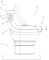
air filtration module 200, as shown inFIGS. 5-11 and15 ,air filtration module 200, includes, in part,air filter 202 andair filtration adaptor 204. Preferably,air filter 202 is a HEPA (or ULPA) air filter that is located within afilter casing 206. Preferably,filter casing 206 is constructed of any suitable, durable, high strength, medical grade material. Preferably,air filtration adaptor 204 is conventionally formed onprotective casing 120. - A unique aspect of the present invention is the use of
air filtration module 200. In particular,air filtration module 200 can be used to filter out air borne contaminants so that they do enter into thesurgical hood 14 andsurgical gown 4. As discussed above, only theair filter 202 extends outside of the surgical hood 14 (FIG. 9 ). In this manner, only air going through theair filtration module 200 will be allowed to enter into thesurgical hood 14 andsurgical gown 4. Also, theair filter 202 can be easily removed and replaced. For example, thewearer 6 can simply remove theair filter 202 and the filter casing 206 from theair filtration adaptor 204. Thewearer 6 can then replace the usedair filter 202 andfilter casing 206 with anew air filter 202 andfilter casing 206 by simply placing thenew air filter 202 andfilter casing 206 onto theair filtration adaptor 204. It is to be understood that theair filter 202 andfilter casing 206 can be retained on theair filtration adaptor 204 by a snap fit, a threaded connection, a bayonet connection, a slidable connection or the like. - Regarding
power module 250, as shown inFIGS. 7 ,8 ,11 ,13 ,15 ,17 , and18 ,power module 250, includes, in part, battery 25,battery doors 254, andbattery lock 256. Preferably,battery 252 is a conventional, rechargeable battery such as a lithium-ion battery or the like that is capable of providing sufficient power to airflow generation module 450 and printed circuit board (PCB)module 500 for an extended period of time such as 6-8 hours. Also,battery doors 254, preferably are constructed of any suitable, durable, high strength, medical grade material. - Another unique aspect of the present invention is the use of
battery doors 254.Battery doors 254 are conventionally connected toprotective casing 120 so thatbattery doors 254 can swing (or pivot) open so thatbattery 252 can be easily installed intopower module 250 or removed frompower module 250. In particular, thewearer 6 can removebattery 252 frompower module 250 by openingbattery doors 254 and removingbattery 252 frompower module 250. Thebattery 252 can then be placed on a conventional battery charger (not shown). Once thebattery 252 has been fully charged, thewearer 6 can then remove the battery charger, open thebattery doors 254, and slide thebattery 252 into thepower module 250 so that thebattery 252 is securely retained within thepower module 250. Thewearer 6 then closes thebattery doors 254 so that thebattery 252 is not exposed to the elements. It is to be understood that aconventional locking mechanism 256 can be used to lock thebattery 252 in place in thepower module 250 so that thebattery 252 does not inadvertently come loose while theventilation system 100 is being operated. - With respect to
yoke module 300, as shown inFIGS. 7-10 ,12 13 ,17 , an18 ,yoke module 300, includes, in part,yoke 302 andyoke connectors 304. Preferably,yoke 302 is constructed of any suitable, durable, high strength, flexible, medical grade material. Preferably,yoke connectors 304 are attached to the back ofprotective casing 120. - Another unique aspect of the present invention is the use of
yoke module 300. In particular,yoke module 300 can be used to assist in retainingventilation system 100 on the shoulders of thewearer 6. In particular,yoke 302 is removably attached to protective casing through the use ofyoke connectors 304. In this manner,yoke 302 can be easily attached to and removed fromprotective casing 120. Furthermore, sinceyoke 302 is flexible,yoke 302 can be adjusted so as to fit the upper torso of thewearer 6 so thatventilation system 100 will remain securely retained on the shoulders and the upper torso of thewearer 6. For example, thewearer 6 can position the ventilation system with theyoke module 300 installed over his/her head and place theyoke module 300 on the upper torso of thewearer 6. Thewearer 6 can then pull/push onyoke 302 whileyoke 302 is connected toyoke connectors 304 so thatyoke 302 firmly contacts the upper torso of thewearer 6 in order to assist in retaining theventilation system 100 on the shoulders and upper torso of thewearer 6. - Regarding
neck vent module 350, as shown inFIGS. 8-10 , and12-18 ,neck vent module 350, includes, in part,neck vent 352,neck vent opening 354, and neckvent adjustment lever 356. Preferably,neck vent 352,neck vent opening 354, and neckvent adjustment lever 356 are constructed of any suitable, durable, high strength, medical grade material. Also, neck vent opening 354 is formed inneck vent 352 by conventional techniques such as forming, cutting, molding or the like. - Another unique aspect of the present invention is the use of
neck vent module 350. In particular,neck vent module 350 can be used to direct the flow of air onto the back of the neck, the upper shoulder area, and the lower back of the head of thewearer 6. For example, thewearer 6 can change the direction of the air coming out of neck vent opening 354 by manipulating the neckvent adjustment lever 356 in order to change an orientation of theneck vent 352. As shown inFIG. 12 , thewearer 6 can move the neckvent adjustment lever 356 up or down along the direction of arrows A in order to direct the air coming out of neck vent opening 354 to the desired location on the back of the neck, the upper shoulder area, and the lower back of the head of thewearer 6. - With respect to
down tube module 400, as shown inFIGS. 8 ,12 , and13 ,down tube module 400, includes, in part,down tubes 402,down tube connectors 404,down tube openings 406, and down tubeair flow openings 408. Preferably,down tubes 402 are constructed of any suitable, durable, high strength, flexible, medical grade material. Also,down tube connectors 404 are constructed of any suitable, durable, high strength, rigid, medical grade material. It is to be understood that down tubeair flow openings 408 are formed indown tubes 402 by conventional tube opening techniques such as forming, cutting, casting or the like. Furthermore, it is to be understood that downtubes 402 should be long enough so as to assist in providing air to the upper torso of thewearer 6, as will be described in greater detail later. - Another unique aspect of the present invention is the use of
down tube module 400. In particular,down tube connectors 404 are conventionally retained within downtube openings 406. Each of thedown tubes 402 are then connected at one end to a downtube connectors 404 through the use of ridges 410 on down tube connectors 404 (FIG. 12 ) so that the down tubes are conventionally secured to thedown tube connectors 404. As theventilation system 100 is providing air to thewearer 6, air is also being emitted from the down tubeair flow openings 408 across the upper torso of thewearer 6. In this manner, the upper torso of thewearer 6 is being cooled. It is to be understood that the direction at which the air is being emitted from the down tubeair flow openings 408 can be adjusted by twisted or rotating thedown tubes 402. - Regarding air
flow generation module 450, as shown inFIGS. 15 and16 , airflow generation module 450, includes, in part, conventional electrical motor 452,conventional impeller 454, and backflow opening 456. It is to be understood thatbattery 252 provides the electrical power to electrical motor 452. - Another unique aspect of the present invention is the use of air
flow generation module 450. In particular, as the electrical motor 452 causes theimpeller 454 to rotate, the configuration of theimpeller 454 causes air to be drawn through theair filter module 200 in the direction of arrow C (FIG. 15 ). In this manner, theair filter module 200 can be used to filter the air being drawn into theventilation system 100. Also, the back flow opening 456 is provided in order to allow air that is contained within thesurgical hood 14 to also be drawn through back flow opening 456 in the direction of arrows D. In this manner, the back flow opening 456 provides for an even greater circulation of the air within thehood 14 while theventilation system 100 is in operation. Furthermore, as shown inFIG. 15 , only a portion of thefilter module 200, preferably theair filter 202, extends outside of thesurgical hood 14. - With respect to printed circuit board (PCB)
module 500, as shown inFIG. 18 , printedcircuit board module 500, includes, in part, a conventional printedcircuit board 502. It is to be understood that printedcircuit board 502 can be used to control theventilation system 100. In particular, printedcircuit board 502 can be used to control the speed at which the impeller 454 (FIG. 15 ) rotates, thereby controlling the velocity of the air being emitted from the face vents 152, theneck vent 352, and thedown tubes 402. It is to be further understood that the printedcircuit board 502 is located in the rear of theprotective casing 120 so that the printed circuit board can be located adjacent to thebattery 252. Finally, it is to be understood that the printedcircuit board 502 is conventionally retained within the protective casing 102 by conventional fasteners (not shown). - Another unique aspect of the present invention is the use of
ventilation system 100. As shown inFIGS. 5-18 , as the electrical motor 452 causes theimpeller 454 to rotate, the configuration of theimpeller 454 causes air to be drawn through theair filter module 200 in the direction of arrow C (FIG. 15 ). In this manner, theair filter module 200 can be used to filter the air being drawn into theventilation system 100. Also, the back flow opening 456 is provided in order to allow air that is contained within thehood 14 to also be drawn through back flow opening 456 in the direction of arrow D. In this manner, air (or other similar gases) is introduced into the inside ofhood 14. Theface vent module 150 is used as a "yoke" to support theventilation system 100 upon the shoulders ofwearer 6. As air is introduced into the inside ofhood 14, face vents 152,neck vent 352, and downtubes 402 cause the air to go up and around the head ofwearer 6 and across the torso of thewearer 6 in order to cool the head, neck, and torso areas of wearer 6 (FIG. 5 ). - The preceding merely illustrates the principles of the invention. It will thus be appreciated that those skilled in the art will be able to devise various arrangements which, although not explicitly described or shown herein, embody the principles of the invention and are included within its spirit and scope. Furthermore, all examples and conditional language recited herein are principally intended expressly to be only for pedagogical purposes and to aid the reader in understanding the principles of the invention and the concepts contributed by the inventors to furthering the art, and are to be construed as being without limitation to such specifically recited examples and conditions. Moreover, all statements herein reciting principles, aspects, and embodiments of the invention, as well as specific examples thereof, are intended to encompass both structural and functional equivalents thereof. Additionally, it is intended that such equivalents include both currently known equivalents and equivalents developed in the future, i.e., any elements developed that perform the same function, regardless of structure.
- This description of the exemplary embodiments is intended to be read in connection with the figures of the accompanying drawing, which are to be considered part of the entire written description. In the description, relative terms such as "lower," "upper," "horizontal," "vertical," "above," "below," "up," "down," "top" and "bottom" as well as derivatives thereof (e.g., "horizontally," "downwardly," "upwardly," etc.) should be construed to refer to the orientation as then described or as shown in the drawing under discussion. These relative terms are for convenience of description and do not require that the apparatus be constructed or operated in a particular orientation. Terms concerning attachments, coupling and the like, such as "connected" and "interconnected," refer to a relationship wherein structures are secured or attached to one another either directly or indirectly through intervening structures, as well as both movable or rigid attachments or relationships, unless expressly described otherwise.
- All patents, publications, scientific articles, web sites, and other documents and materials referenced or mentioned herein are indicative of the levels of skill of those skilled in the art to which the invention pertains, and each such referenced document and material is hereby incorporated by reference to the same extent as if it had been incorporated by reference in its entirety individually or set forth herein in its entirety. Applicants reserve the right to physically incorporate into this specification any and all materials and information from any such patents, publications, scientific articles, web sites, electronically available information, and other referenced materials or documents to the extent such incorporated materials and information are not inconsistent with the description herein.
- The written description portion of this patent includes all claims. Furthermore, all claims, including all original claims as well as all claims from any and all priority documents, are hereby incorporated by reference in their entirety into the written description portion of the specification, and Applicant(s) reserve the right to physically incorporate into the written description or any other portion of the application, any and all such claims. Thus, for example, under no circumstances may the patent be interpreted as allegedly not providing a written description for a claim on the assertion that the precise wording of the claim is not set forth in haec verba in written description portion of the patent.
- The claims will be interpreted according to law. However, and notwithstanding the alleged or perceived ease or difficulty of interpreting any claim or portion thereof, under no circumstances may any adjustment or amendment of a claim or any portion thereof during prosecution of the application or applications leading to this patent be interpreted as having forfeited any right to any and all equivalents thereof that do not form a part of the prior art.
- All of the features disclosed in this specification may be combined in any combination. Thus, unless expressly stated otherwise, each feature disclosed is only an example of a generic series of equivalent or similar features.
- It is to be understood that while the invention has been described in conjunction with the detailed description thereof, the foregoing description is intended to illustrate and not limit the scope of the invention, which is defined by the scope of the appended claims. Other aspects, advantages, and modifications are within the scope of the following claims and the present invention is not limited except as by the appended claims.
- The specific methods and compositions described herein are representative of preferred embodiments and are exemplary and not intended as limitations on the scope of the invention. Other objects, aspects, and embodiments will occur to those skilled in the art upon consideration of this specification, and are encompassed within the spirit of the invention as defined by the scope of the claims. The invention illustratively described herein suitably may be practiced in the absence of any element or elements, or limitation or limitations, which is not specifically disclosed herein as essential. Thus, for example, in each instance herein, in embodiments or examples of the present invention, the terms "comprising," "including," "containing," etc. are to be read expansively and without limitation. The methods and processes illustratively described herein suitably may be practiced in differing orders of steps, and that they are not necessarily restricted to the orders of steps indicated herein or in the claims.
- The terms and expressions that have been employed are used as terms of description and not of limitation, and there is no intent in the use of such terms and expressions to exclude any equivalent of the features shown and described or portions thereof, but it is recognized that various modifications are possible within the scope of the invention as claimed. Thus, it will be understood that although the present invention has been specifically disclosed by various embodiments and/or preferred embodiments and optional features, any and all modifications and variations of the concepts herein disclosed that may be resorted to by those skilled in the art are considered to be within the scope of this invention as defined by the appended claims.
- The invention has been described broadly and generically herein. Each of the narrower species and sub-generic groupings falling within the generic disclosure also form part of the invention. This includes the generic description of the invention with a proviso or negative limitation removing any subject matter from the genus, regardless of whether or not the excised material is specifically recited herein.
- Other embodiments are within the following claims. Therefore, the patent may not be interpreted to be limited to the specific examples or embodiments or methods specifically and/or expressly disclosed herein. Under no circumstances may the patent be interpreted to be limited by any statement made by any Examiner or any other official or employee of the Patent and Trademark Office unless such statement is specifically and without qualification or reservation expressly adopted in a responsive writing by Applicants.
- Although the invention has been described in terms of exemplary embodiments, it is not limited thereto. Rather, the appended claims should be construed broadly, to include other variants and embodiments of the invention, which may be made by those skilled in the art without departing from the scope and range of equivalents of the invention.
- Other modifications and implementations will occur to those skilled in the art without departing from the spirit and the scope of the invention as claimed. Accordingly, the description hereinabove is not intended to limit the invention, except as indicated in the appended claims.
- Therefore, provided herein is a new and improved helmetless support and lightweight ventilation system for use with surgical hoods and gowns. The preferred helmetless support and lightweight ventilation system for use with surgical hoods and gowns, according to various embodiments of the present invention, offers the following advantages: ease of use; lightness in weight; durability; the ability to distribute the device weight along the shoulders of the wearer while maintaining full mobility and greatly reducing head and neck fatigue; adjustability of the fan speed; the ability to control the amount and direction of the output from each of the various ventilation system output apertures; the ability to provide a contiguous head/hood covering; the ability to filter the air contacting the wearer; the use of front offsets to provide for air circulation around the head and neck areas of the wearer; the ability to remove the face vents for ease of cleaning or sanitizing; the ability to provide air flow within the hood; and compactness of the device.
- In fact, in many of the preferred embodiments, these advantages of ease of use, lightness in weight, durability, the ability to distribute the device weight along the shoulders of the wearer while maintaining full mobility and greatly reducing head and neck fatigue, adjustability of the fan speed, the ability to control the amount and direction of the output from each of the various ventilation system output apertures, the ability to provide a contiguous head/hood covering, the ability to filter the air contacting the wearer, the use of front offsets to provide for air circulation around the head and neck areas of the wearer, the ability to remove the face vents for ease of cleaning or sanitizing, the ability to provide air flow within the hood, and compactness of the device are optimized to an extent that is considerably higher than heretofore achieved in prior, known support and ventilation systems for use with surgical hoods and gowns.
Claims (9)
- A ventilation system (100) for use with surgical hoods and gowns, wherein the ventilation system is further comprised of:a protective casing (120);a face vent module (150) located on one side of the protective casing;an air filtration module (200) located on the other side of the protective casing;a power module (250) located adjacent to the face vent module;a yoke module (300) located between the face vent module and the power module;a neck vent module (350) located adjacent to the yoke module;a down tube module (400) located adjacent to the neck vent module; andan air flow generation module (450) located between the power module and the air filtration module;wherein the face vent module is further comprised of:a plurality of face vent connectors (156) operatively connected to the other side of the protective casing;a plurality of removable face vents (152), wherein each of the plurality of removable face vents is operatively connected to each of the plurality of face vent connectors such that a position of each of the removable face vents can be adjusted;a plurality of face vent openings (154) located substantially along a portion of each of the plurality of removable face vents; anda plurality of face vent air flow adjustors (160), wherein each of the plurality of face vent flow adjustors is located adjacent to the plurality of face vent connectors.
- The ventilation system according to claim 1, wherein the air filtration module is further comprised of:an air filtration adaptor operatively connected to the one side of the protective casing;an air filter operatively connected to the air filtration adaptor;a stretchable opening located in a back of the hood that seals around the air filtration adaptor in order to ensure that all air brought into the surgical gown and surgical hood is forced to pass through the filter; anda lanyard located adjacent to the opening and releasably connected to a portion of the surgical gown, wherein the lanyard can be used when self-doffing of the surgical gown in order to facilitate removal of the surgical hood from the air filter adaptor.
- The ventilation system according to claim 1, wherein the yoke module is further comprised of:a plurality of yoke connectors operatively connected to the other side of the protective casing; anda yoke such that the yoke is removable connected to the plurality of yoke connectors;or wherein the neck vent module is further comprised of:a neck vent operatively connected to the other side of the protective casing;a neck vent opening located along a portion of the neck vent; anda neck vent adjustment lever operatively connected to the neck vent in order to adjust an orientation of the neck vent;
- The ventilation system according to claim 1, wherein the down tube module is further comprised of:a plurality of down tube connectors operatively connected to the other side of the protective casing;a plurality of down tubes, wherein each of the plurality of down tubes is removably connected to each of the plurality of down tube connectors; anda plurality of down tube air flow openings located along a portion of each of the plurality of down tubes.
- A helmetless support and ventilation system for use with surgical hoods and gowns, comprising:a helmetless support (2), the helmetless support comprises:a flexible band (52);
a plurality of front offsets (53), wherein each of the plurality of front offsets has a first end and a second end such that the first end of each of the front offsets is operatively connected to a portion of the flexible band;an offset extension (57) having a first end and a second end such that the second end of each of the plurality of front offsets is operatively connected to the first end of the offset extension and the offset extension is located at a predetermined distance away from the flexible band;a plurality of faceplate attachment extensions (64), wherein each of the plurality of faceplate attachment extensions is operatively connected to the offset extension;a plurality of support faceplate attachments, such that each of the plurality of support faceplate attachments are operatively connected on one side to eachof the plurality of faceplate attachment extensions;
anda ventilation system (100) according to claim 1, configured to be located within a surgical gown and a surgical hood for providing ventilation air within the surgical gown and the surgical hood, wherein the ventilation system is configured to be retained by shoulders of a wearer of the ventilation system in order to provide ventilation air to a face, neck, and torso of the wearer. - The helmetless support and ventilation system for use with surgical hoods and gowns, according to claim 5, wherein each of the plurality of support faceplate attachments is further comprised of:
a hook and loop fastener or a magnet. - The helmetless support and ventilation system for use with surgical hoods and gowns, according to claim 5, wherein the helmetless support is further comprised of:
a surgical gown having a surgical hood operatively connected to the surgical gown, wherein surgical hood includes a plurality of faceplate attachments such that the faceplate attachments are capable of being removably attached to the plurality of support faceplate attachments such that the helmetless support is used to support the surgical hood and gown. - The helmetless support and ventilation system for use with surgical hoods and gowns, according to claim 5, wherein the helmetless support is further comprised of:
a band adjustment device located on the flexible band such that the band adjustment device can be used to adjust a circumference of the flexible band. - The helmetless support and ventilation system for use with surgical hoods and gowns, according to claim 5, wherein the helmetless support is further comprised of:
an adjustable headband having a plurality of adjustment openings, wherein the adjustable headband is operatively connected to the flexible band in order to adjust a height of the helmetless support.
Applications Claiming Priority (1)
| Application Number | Priority Date | Filing Date | Title |
|---|---|---|---|
| US16/894,938 US10939712B1 (en) | 2020-06-08 | 2020-06-08 | Helmetless support and ventilation system for a surgical hood and gown and methods of making and using same |
Publications (3)
| Publication Number | Publication Date |
|---|---|
| EP3932234A2 EP3932234A2 (en) | 2022-01-05 |
| EP3932234A3 EP3932234A3 (en) | 2022-03-02 |
| EP3932234B1 true EP3932234B1 (en) | 2024-09-18 |
Family
ID=74851573
Family Applications (1)
| Application Number | Title | Priority Date | Filing Date |
|---|---|---|---|
| EP21178368.3A Active EP3932234B1 (en) | 2020-06-08 | 2021-06-08 | A helmetless support and ventilation system for a surgical hood and gown and methods of making and using same |
Country Status (3)
| Country | Link |
|---|---|
| US (1) | US10939712B1 (en) |
| EP (1) | EP3932234B1 (en) |
| AU (1) | AU2021203505A1 (en) |
Families Citing this family (7)
| Publication number | Priority date | Publication date | Assignee | Title |
|---|---|---|---|---|
| US11980781B2 (en) * | 2020-07-09 | 2024-05-14 | Kandis MOSER | Protective clothing and protective shroud/hood with fan |
| US12042680B2 (en) * | 2020-08-07 | 2024-07-23 | Ford Global Technologies, Llc | Electrical control systems for powered air-purifying respirators |
| CN113181573A (en) * | 2021-04-16 | 2021-07-30 | 广州市疾病预防控制中心(广州市卫生检验中心、广州市食品安全风险监测与评估中心、广州医科大学公共卫生研究院) | Electric air supply respiratory protection system and connection structure of filter box thereof |
| CN113209508A (en) * | 2021-04-16 | 2021-08-06 | 广州市疾病预防控制中心(广州市卫生检验中心、广州市食品安全风险监测与评估中心、广州医科大学公共卫生研究院) | Electric air supply respiratory protection system and flow distribution mechanism thereof |
| CN113209509A (en) * | 2021-04-16 | 2021-08-06 | 广州市疾病预防控制中心(广州市卫生检验中心、广州市食品安全风险监测与评估中心、广州医科大学公共卫生研究院) | Electric air supply respiratory protection system |
| IL312384A (en) | 2021-10-27 | 2024-06-01 | Pabban Dev Inc | A system and method for self-defense |
| US20240215665A1 (en) * | 2023-01-03 | 2024-07-04 | Mark T. McBride | System and method for managing operating condition parameters in medical devices |
Citations (2)
| Publication number | Priority date | Publication date | Assignee | Title |
|---|---|---|---|---|
| US20070151002A1 (en) * | 2003-07-18 | 2007-07-05 | Depuy Products, Inc. | Head gear apparatus having improved air flow arrangement |
| US20180325205A1 (en) * | 2017-05-11 | 2018-11-15 | Illinois Tool Works Inc. | Protective headwear with airflow |
Family Cites Families (6)
| Publication number | Priority date | Publication date | Assignee | Title |
|---|---|---|---|---|
| US5655374A (en) * | 1996-02-21 | 1997-08-12 | Surgical Specialty Products, Inc. | Surgical suit |
| US6367085B1 (en) * | 1998-12-21 | 2002-04-09 | 3M Innovative Properties Company | Head suspension for an air supplied hood system |
| KR101779244B1 (en) | 2011-02-14 | 2017-09-18 | 티.에이치.아이. 토탈 헬스케어 이노베이션 게엠베하 | Surgical helmet |
| US20150297920A1 (en) * | 2012-11-30 | 2015-10-22 | Koken Ltd. | Air blower and protective suit including the same |
| AU2013260673A1 (en) * | 2012-12-10 | 2014-06-26 | Medline Industries, Inc. | Protective Apparel and SUpport Apparatus and Method of Use |
| US20160128396A1 (en) * | 2014-11-06 | 2016-05-12 | Roger Clemente | Air distribution system for individual cooling |
-
2020
- 2020-06-08 US US16/894,938 patent/US10939712B1/en active Active
-
2021
- 2021-05-28 AU AU2021203505A patent/AU2021203505A1/en active Pending
- 2021-06-08 EP EP21178368.3A patent/EP3932234B1/en active Active
Patent Citations (2)
| Publication number | Priority date | Publication date | Assignee | Title |
|---|---|---|---|---|
| US20070151002A1 (en) * | 2003-07-18 | 2007-07-05 | Depuy Products, Inc. | Head gear apparatus having improved air flow arrangement |
| US20180325205A1 (en) * | 2017-05-11 | 2018-11-15 | Illinois Tool Works Inc. | Protective headwear with airflow |
Also Published As
| Publication number | Publication date |
|---|---|
| EP3932234A2 (en) | 2022-01-05 |
| US10939712B1 (en) | 2021-03-09 |
| AU2021203505A1 (en) | 2021-12-23 |
| EP3932234A3 (en) | 2022-03-02 |
Similar Documents
| Publication | Publication Date | Title |
|---|---|---|
| US10939712B1 (en) | Helmetless support and ventilation system for a surgical hood and gown and methods of making and using same | |
| CA2589371C (en) | Protective headgear system with filter protector | |
| US12582180B2 (en) | Protective apparel and support apparatus and method of use | |
| JP2676071B2 (en) | Air flow and filter system | |
| US6918141B2 (en) | Protective headgear system | |
| EP2688434B1 (en) | Protective apparel and support apparatus | |
| US7200873B2 (en) | Head gear apparatus having improved air flow arrangement | |
| EP0847295A1 (en) | Surgical helmet | |
| CN115956730A (en) | Surgical helmets including adjustment mechanisms | |
| AU2013260673A1 (en) | Protective Apparel and SUpport Apparatus and Method of Use | |
| AU2017210506B2 (en) | Protective apparel and support apparatus | |
| HK1110818B (en) | Protective headgear system with filter protector |
Legal Events
| Date | Code | Title | Description |
|---|---|---|---|
| PUAI | Public reference made under article 153(3) epc to a published international application that has entered the european phase |
Free format text: ORIGINAL CODE: 0009012 |
|
| STAA | Information on the status of an ep patent application or granted ep patent |
Free format text: STATUS: THE APPLICATION HAS BEEN PUBLISHED |
|
| AK | Designated contracting states |
Kind code of ref document: A2 Designated state(s): AL AT BE BG CH CY CZ DE DK EE ES FI FR GB GR HR HU IE IS IT LI LT LU LV MC MK MT NL NO PL PT RO RS SE SI SK SM TR |
|
| PUAL | Search report despatched |
Free format text: ORIGINAL CODE: 0009013 |
|
| AK | Designated contracting states |
Kind code of ref document: A3 Designated state(s): AL AT BE BG CH CY CZ DE DK EE ES FI FR GB GR HR HU IE IS IT LI LT LU LV MC MK MT NL NO PL PT RO RS SE SI SK SM TR |
|
| RIC1 | Information provided on ipc code assigned before grant |
Ipc: A62B 18/00 20060101ALN20220125BHEP Ipc: A41D 13/002 20060101ALI20220125BHEP Ipc: A41D 27/28 20060101ALI20220125BHEP Ipc: A41D 13/12 20060101AFI20220125BHEP |
|
| STAA | Information on the status of an ep patent application or granted ep patent |
Free format text: STATUS: REQUEST FOR EXAMINATION WAS MADE |
|
| 17P | Request for examination filed |
Effective date: 20220717 |
|
| RBV | Designated contracting states (corrected) |
Designated state(s): AL AT BE BG CH CY CZ DE DK EE ES FI FR GB GR HR HU IE IS IT LI LT LU LV MC MK MT NL NO PL PT RO RS SE SI SK SM TR |
|
| P01 | Opt-out of the competence of the unified patent court (upc) registered |
Effective date: 20230908 |
|
| GRAP | Despatch of communication of intention to grant a patent |
Free format text: ORIGINAL CODE: EPIDOSNIGR1 |
|
| STAA | Information on the status of an ep patent application or granted ep patent |
Free format text: STATUS: GRANT OF PATENT IS INTENDED |
|
| INTG | Intention to grant announced |
Effective date: 20240425 |
|
| GRAS | Grant fee paid |
Free format text: ORIGINAL CODE: EPIDOSNIGR3 |
|
| GRAA | (expected) grant |
Free format text: ORIGINAL CODE: 0009210 |
|
| STAA | Information on the status of an ep patent application or granted ep patent |
Free format text: STATUS: THE PATENT HAS BEEN GRANTED |
|
| AK | Designated contracting states |
Kind code of ref document: B1 Designated state(s): AL AT BE BG CH CY CZ DE DK EE ES FI FR GB GR HR HU IE IS IT LI LT LU LV MC MK MT NL NO PL PT RO RS SE SI SK SM TR |
|
| REG | Reference to a national code |
Ref country code: GB Ref legal event code: FG4D |
|
| REG | Reference to a national code |
Ref country code: CH Ref legal event code: EP |
|
| REG | Reference to a national code |
Ref country code: DE Ref legal event code: R096 Ref document number: 602021018863 Country of ref document: DE |
|
| REG | Reference to a national code |
Ref country code: IE Ref legal event code: FG4D |
|
| REG | Reference to a national code |
Ref country code: NL Ref legal event code: FP |
|
| REG | Reference to a national code |
Ref country code: LT Ref legal event code: MG9D |
|
| PG25 | Lapsed in a contracting state [announced via postgrant information from national office to epo] |
Ref country code: NO Free format text: LAPSE BECAUSE OF FAILURE TO SUBMIT A TRANSLATION OF THE DESCRIPTION OR TO PAY THE FEE WITHIN THE PRESCRIBED TIME-LIMIT Effective date: 20241218 |
|
| PG25 | Lapsed in a contracting state [announced via postgrant information from national office to epo] |
Ref country code: GR Free format text: LAPSE BECAUSE OF FAILURE TO SUBMIT A TRANSLATION OF THE DESCRIPTION OR TO PAY THE FEE WITHIN THE PRESCRIBED TIME-LIMIT Effective date: 20241219 Ref country code: FI Free format text: LAPSE BECAUSE OF FAILURE TO SUBMIT A TRANSLATION OF THE DESCRIPTION OR TO PAY THE FEE WITHIN THE PRESCRIBED TIME-LIMIT Effective date: 20240918 |
|
| PG25 | Lapsed in a contracting state [announced via postgrant information from national office to epo] |
Ref country code: BG Free format text: LAPSE BECAUSE OF FAILURE TO SUBMIT A TRANSLATION OF THE DESCRIPTION OR TO PAY THE FEE WITHIN THE PRESCRIBED TIME-LIMIT Effective date: 20240918 |
|
| PG25 | Lapsed in a contracting state [announced via postgrant information from national office to epo] |
Ref country code: LV Free format text: LAPSE BECAUSE OF FAILURE TO SUBMIT A TRANSLATION OF THE DESCRIPTION OR TO PAY THE FEE WITHIN THE PRESCRIBED TIME-LIMIT Effective date: 20240918 |
|
| PG25 | Lapsed in a contracting state [announced via postgrant information from national office to epo] |
Ref country code: HR Free format text: LAPSE BECAUSE OF FAILURE TO SUBMIT A TRANSLATION OF THE DESCRIPTION OR TO PAY THE FEE WITHIN THE PRESCRIBED TIME-LIMIT Effective date: 20240918 |
|
| PG25 | Lapsed in a contracting state [announced via postgrant information from national office to epo] |
Ref country code: RS Free format text: LAPSE BECAUSE OF FAILURE TO SUBMIT A TRANSLATION OF THE DESCRIPTION OR TO PAY THE FEE WITHIN THE PRESCRIBED TIME-LIMIT Effective date: 20241218 |
|
| PG25 | Lapsed in a contracting state [announced via postgrant information from national office to epo] |
Ref country code: RS Free format text: LAPSE BECAUSE OF FAILURE TO SUBMIT A TRANSLATION OF THE DESCRIPTION OR TO PAY THE FEE WITHIN THE PRESCRIBED TIME-LIMIT Effective date: 20241218 Ref country code: NO Free format text: LAPSE BECAUSE OF FAILURE TO SUBMIT A TRANSLATION OF THE DESCRIPTION OR TO PAY THE FEE WITHIN THE PRESCRIBED TIME-LIMIT Effective date: 20241218 Ref country code: LV Free format text: LAPSE BECAUSE OF FAILURE TO SUBMIT A TRANSLATION OF THE DESCRIPTION OR TO PAY THE FEE WITHIN THE PRESCRIBED TIME-LIMIT Effective date: 20240918 Ref country code: HR Free format text: LAPSE BECAUSE OF FAILURE TO SUBMIT A TRANSLATION OF THE DESCRIPTION OR TO PAY THE FEE WITHIN THE PRESCRIBED TIME-LIMIT Effective date: 20240918 Ref country code: GR Free format text: LAPSE BECAUSE OF FAILURE TO SUBMIT A TRANSLATION OF THE DESCRIPTION OR TO PAY THE FEE WITHIN THE PRESCRIBED TIME-LIMIT Effective date: 20241219 Ref country code: FI Free format text: LAPSE BECAUSE OF FAILURE TO SUBMIT A TRANSLATION OF THE DESCRIPTION OR TO PAY THE FEE WITHIN THE PRESCRIBED TIME-LIMIT Effective date: 20240918 Ref country code: BG Free format text: LAPSE BECAUSE OF FAILURE TO SUBMIT A TRANSLATION OF THE DESCRIPTION OR TO PAY THE FEE WITHIN THE PRESCRIBED TIME-LIMIT Effective date: 20240918 |
|
| REG | Reference to a national code |
Ref country code: AT Ref legal event code: MK05 Ref document number: 1723917 Country of ref document: AT Kind code of ref document: T Effective date: 20240918 |
|
| PG25 | Lapsed in a contracting state [announced via postgrant information from national office to epo] |
Ref country code: PT Free format text: LAPSE BECAUSE OF FAILURE TO SUBMIT A TRANSLATION OF THE DESCRIPTION OR TO PAY THE FEE WITHIN THE PRESCRIBED TIME-LIMIT Effective date: 20250120 Ref country code: IS Free format text: LAPSE BECAUSE OF FAILURE TO SUBMIT A TRANSLATION OF THE DESCRIPTION OR TO PAY THE FEE WITHIN THE PRESCRIBED TIME-LIMIT Effective date: 20250118 |
|
| PG25 | Lapsed in a contracting state [announced via postgrant information from national office to epo] |
Ref country code: RO Free format text: LAPSE BECAUSE OF FAILURE TO SUBMIT A TRANSLATION OF THE DESCRIPTION OR TO PAY THE FEE WITHIN THE PRESCRIBED TIME-LIMIT Effective date: 20240918 Ref country code: SM Free format text: LAPSE BECAUSE OF FAILURE TO SUBMIT A TRANSLATION OF THE DESCRIPTION OR TO PAY THE FEE WITHIN THE PRESCRIBED TIME-LIMIT Effective date: 20240918 |
|
| PG25 | Lapsed in a contracting state [announced via postgrant information from national office to epo] |
Ref country code: ES Free format text: LAPSE BECAUSE OF FAILURE TO SUBMIT A TRANSLATION OF THE DESCRIPTION OR TO PAY THE FEE WITHIN THE PRESCRIBED TIME-LIMIT Effective date: 20240918 |
|
| PG25 | Lapsed in a contracting state [announced via postgrant information from national office to epo] |
Ref country code: EE Free format text: LAPSE BECAUSE OF FAILURE TO SUBMIT A TRANSLATION OF THE DESCRIPTION OR TO PAY THE FEE WITHIN THE PRESCRIBED TIME-LIMIT Effective date: 20240918 Ref country code: AT Free format text: LAPSE BECAUSE OF FAILURE TO SUBMIT A TRANSLATION OF THE DESCRIPTION OR TO PAY THE FEE WITHIN THE PRESCRIBED TIME-LIMIT Effective date: 20240918 |
|
| PG25 | Lapsed in a contracting state [announced via postgrant information from national office to epo] |
Ref country code: PL Free format text: LAPSE BECAUSE OF FAILURE TO SUBMIT A TRANSLATION OF THE DESCRIPTION OR TO PAY THE FEE WITHIN THE PRESCRIBED TIME-LIMIT Effective date: 20240918 Ref country code: CZ Free format text: LAPSE BECAUSE OF FAILURE TO SUBMIT A TRANSLATION OF THE DESCRIPTION OR TO PAY THE FEE WITHIN THE PRESCRIBED TIME-LIMIT Effective date: 20240918 |
|
| PG25 | Lapsed in a contracting state [announced via postgrant information from national office to epo] |
Ref country code: SK Free format text: LAPSE BECAUSE OF FAILURE TO SUBMIT A TRANSLATION OF THE DESCRIPTION OR TO PAY THE FEE WITHIN THE PRESCRIBED TIME-LIMIT Effective date: 20240918 Ref country code: IT Free format text: LAPSE BECAUSE OF FAILURE TO SUBMIT A TRANSLATION OF THE DESCRIPTION OR TO PAY THE FEE WITHIN THE PRESCRIBED TIME-LIMIT Effective date: 20240918 |
|
| REG | Reference to a national code |
Ref country code: DE Ref legal event code: R097 Ref document number: 602021018863 Country of ref document: DE |
|
| PGFP | Annual fee paid to national office [announced via postgrant information from national office to epo] |
Ref country code: DE Payment date: 20250610 Year of fee payment: 5 |
|
| PG25 | Lapsed in a contracting state [announced via postgrant information from national office to epo] |
Ref country code: DK Free format text: LAPSE BECAUSE OF FAILURE TO SUBMIT A TRANSLATION OF THE DESCRIPTION OR TO PAY THE FEE WITHIN THE PRESCRIBED TIME-LIMIT Effective date: 20240918 |
|
| PGFP | Annual fee paid to national office [announced via postgrant information from national office to epo] |
Ref country code: GB Payment date: 20250616 Year of fee payment: 5 |
|
| PGFP | Annual fee paid to national office [announced via postgrant information from national office to epo] |
Ref country code: NL Payment date: 20250611 Year of fee payment: 5 |
|
| PGFP | Annual fee paid to national office [announced via postgrant information from national office to epo] |
Ref country code: FR Payment date: 20250611 Year of fee payment: 5 |
|
| PLBE | No opposition filed within time limit |
Free format text: ORIGINAL CODE: 0009261 |
|
| STAA | Information on the status of an ep patent application or granted ep patent |
Free format text: STATUS: NO OPPOSITION FILED WITHIN TIME LIMIT |
|
| PGFP | Annual fee paid to national office [announced via postgrant information from national office to epo] |
Ref country code: IE Payment date: 20250610 Year of fee payment: 5 |
|
| 26N | No opposition filed |
Effective date: 20250619 |
|
| PG25 | Lapsed in a contracting state [announced via postgrant information from national office to epo] |
Ref country code: SE Free format text: LAPSE BECAUSE OF FAILURE TO SUBMIT A TRANSLATION OF THE DESCRIPTION OR TO PAY THE FEE WITHIN THE PRESCRIBED TIME-LIMIT Effective date: 20240918 |
|
| REG | Reference to a national code |
Ref country code: CH Ref legal event code: H13 Free format text: ST27 STATUS EVENT CODE: U-0-0-H10-H13 (AS PROVIDED BY THE NATIONAL OFFICE) Effective date: 20260127 |
|
| PG25 | Lapsed in a contracting state [announced via postgrant information from national office to epo] |
Ref country code: MC Free format text: LAPSE BECAUSE OF FAILURE TO SUBMIT A TRANSLATION OF THE DESCRIPTION OR TO PAY THE FEE WITHIN THE PRESCRIBED TIME-LIMIT Effective date: 20240918 |
|
| PG25 | Lapsed in a contracting state [announced via postgrant information from national office to epo] |
Ref country code: LU Free format text: LAPSE BECAUSE OF NON-PAYMENT OF DUE FEES Effective date: 20250608 |
|
| REG | Reference to a national code |
Ref country code: BE Ref legal event code: MM Effective date: 20250630 |
|
| PG25 | Lapsed in a contracting state [announced via postgrant information from national office to epo] |
Ref country code: BE Free format text: LAPSE BECAUSE OF NON-PAYMENT OF DUE FEES Effective date: 20250630 |
|
| PG25 | Lapsed in a contracting state [announced via postgrant information from national office to epo] |
Ref country code: CH Free format text: LAPSE BECAUSE OF NON-PAYMENT OF DUE FEES Effective date: 20250630 |
|
| PG25 | Lapsed in a contracting state [announced via postgrant information from national office to epo] |
Ref country code: LT Free format text: LAPSE BECAUSE OF FAILURE TO SUBMIT A TRANSLATION OF THE DESCRIPTION OR TO PAY THE FEE WITHIN THE PRESCRIBED TIME-LIMIT Effective date: 20240918 |
|
| PG25 | Lapsed in a contracting state [announced via postgrant information from national office to epo] |
Ref country code: CY Free format text: LAPSE BECAUSE OF FAILURE TO SUBMIT A TRANSLATION OF THE DESCRIPTION OR TO PAY THE FEE WITHIN THE PRESCRIBED TIME-LIMIT Effective date: 20240918 |