EP3932179A1 - Large square baler with pre-compression chamber having removeable access panel - Google Patents
Large square baler with pre-compression chamber having removeable access panel Download PDFInfo
- Publication number
- EP3932179A1 EP3932179A1 EP21179210.6A EP21179210A EP3932179A1 EP 3932179 A1 EP3932179 A1 EP 3932179A1 EP 21179210 A EP21179210 A EP 21179210A EP 3932179 A1 EP3932179 A1 EP 3932179A1
- Authority
- EP
- European Patent Office
- Prior art keywords
- access panel
- transverse edge
- housing
- rearward
- access
- Prior art date
- Legal status (The legal status is an assumption and is not a legal conclusion. Google has not performed a legal analysis and makes no representation as to the accuracy of the status listed.)
- Granted
Links
Images



Classifications
-
- A—HUMAN NECESSITIES
- A01—AGRICULTURE; FORESTRY; ANIMAL HUSBANDRY; HUNTING; TRAPPING; FISHING
- A01F—PROCESSING OF HARVESTED PRODUCE; HAY OR STRAW PRESSES; DEVICES FOR STORING AGRICULTURAL OR HORTICULTURAL PRODUCE
- A01F15/00—Baling presses for straw, hay or the like
- A01F15/08—Details
- A01F15/10—Feeding devices for the crop material e.g. precompression devices
- A01F15/101—Feeding at right angles to the compression stroke
-
- A—HUMAN NECESSITIES
- A01—AGRICULTURE; FORESTRY; ANIMAL HUSBANDRY; HUNTING; TRAPPING; FISHING
- A01F—PROCESSING OF HARVESTED PRODUCE; HAY OR STRAW PRESSES; DEVICES FOR STORING AGRICULTURAL OR HORTICULTURAL PRODUCE
- A01F15/00—Baling presses for straw, hay or the like
- A01F15/08—Details
- A01F15/10—Feeding devices for the crop material e.g. precompression devices
-
- A—HUMAN NECESSITIES
- A01—AGRICULTURE; FORESTRY; ANIMAL HUSBANDRY; HUNTING; TRAPPING; FISHING
- A01F—PROCESSING OF HARVESTED PRODUCE; HAY OR STRAW PRESSES; DEVICES FOR STORING AGRICULTURAL OR HORTICULTURAL PRODUCE
- A01F15/00—Baling presses for straw, hay or the like
- A01F15/04—Plunger presses
-
- A—HUMAN NECESSITIES
- A01—AGRICULTURE; FORESTRY; ANIMAL HUSBANDRY; HUNTING; TRAPPING; FISHING
- A01F—PROCESSING OF HARVESTED PRODUCE; HAY OR STRAW PRESSES; DEVICES FOR STORING AGRICULTURAL OR HORTICULTURAL PRODUCE
- A01F15/00—Baling presses for straw, hay or the like
- A01F15/08—Details
- A01F15/10—Feeding devices for the crop material e.g. precompression devices
- A01F15/101—Feeding at right angles to the compression stroke
- A01F2015/102—Feeding at right angles to the compression stroke the pressing chamber is fed from the bottom side
Definitions
- the disclosure generally relates to a baler implement.
- Agricultural balers gather, compress, and shape crop material into a bale.
- balers which create parallelepiped bales, i.e., square bales, or cylindrical bales, i.e., round bales.
- One exemplary baler is often referred to as a large square baler.
- Large square balers have been used in crop harvesting for many years, and utilize a compression system including a gearbox with a crank arm and connecting rod which are attached to a reciprocating plunger. During each rotation of the crank arm, the reciprocating plunger compresses the crop in a baling or compression chamber as the plunger moves towards the rear of the baler.
- the large square balers form the crop material into a bale having a parallelepiped shape.
- a large square baler includes a pick-up with gathers crop material from a ground surface of the field and moves the gathered crop material into a pre-compression passageway.
- the crop material is collected in the pre-compression passageway until the plunger is retracted, at which time a plurality of feeder forks move the collected crop material from the pre-compression passageway, through a chamber inlet, and into the compression chamber.
- Certain operating and/or crop conditions may cause the pre-compression passageway to become plugged with crop material, such that the feeder forks are unable to move the crop material into the compression chamber.
- a baler implement includes a pick-up that is operable to gather and move crop material.
- a housing extends along a central longitudinal axis between a forward end and a rearward end.
- the housing includes a bottom wall partially defining a compression chamber.
- the bottom wall defines a chamber inlet for supplying the crop material into the compression chamber.
- a lower passage wall defines a lower boundary of a pre-compression passageway.
- the pre-compression passageway interconnects the pick-up and the chamber inlet.
- the lower passage wall includes a forward portion and an access panel. The forward portion of the lower passage wall is positioned proximate the pick-up.
- the access panel is moveable between an operating position for guiding crop material from the pick-up to the chamber inlet, and an access position for providing access to the pre-compression passageway.
- the access panel includes a first transverse edge and a second transverse edge.
- the first transverse edge is positioned forward of the second transverse edge relative to the forward end of the housing.
- the first transverse edge is positioned vertically below the second transverse edge relative to an elevation of the bottom wall of the housing when the access panel is disposed in the operating position.
- a pivotable connection interconnects the forward portion and the access panel of the lower passage wall.
- the pivotable connection is disposed proximate the first transverse edge of the access panel, such that the second transverse edge of the access panel moves vertically relative to the elevation of the bottom wall as the access panel moves between the operating position and the access position to provide access into the pre-compression passageway. Access to the pre-compression passageway is thereby provided between the second transverse edge and the bottom wall of the housing.
- the access panel may thus rest on a ground surface when disposed in the access position, without hanging down and interfering with access to the pre-compression passageway, thereby providing access to the pre-compression passageway from the rear of the baler implement.
- the lower passage wall includes a rearward portion that is positioned proximate the chamber inlet.
- the access panel is positioned between the forward portion and the rearward portion along the central longitudinal axis.
- the rearward portion of the lower passage wall includes a lower transverse edge positioned adjacent the second traverse edge of the access panel when the access panel is disposed in the operating position.
- the rearward portion further includes an upper transverse edge positioned adjacent to the bottom wall and proximate to the chamber inlet. The lower transverse edge of the rearward portion and the second transverse edge of the access panel may be disposed in interlocking engagement when the access panel is positioned in the operating position.
- the second transverse edge of the access panel defines an inner lip and the lower transverse edge of the rearward portion defines an outer lip.
- the inner lip of the access panel is positioned inward of the outer lip of the rearward portion relative to the pre-compression passageway. As such, the outer lip of the rearward portion operates to secure the access panel in the operating position.
- the upper transverse edge of the rearward portion is rotatably attached to the housing for rotational movement about a transverse axis relative to the housing.
- the baler implement may further include a rearward latch interconnecting the rearward portion of the lower passage wall and the housing. The rearward latch is operable to secure the rearward portion relative to the housing when the access panel is disposed in the operating position.
- the rearward portion is non-moveable relative to the housing. With the rearward portion fixed in position and not moveable relative to the housing, the rearward latch is not necessary, and may be omitted.
- the first transverse edge of the access panel defines an exterior lip and a rear transverse edge of the first portion defines an interior lip.
- the interior lip of the first portion is positioned inward of the exterior lip of the access panel, relative to the pre-compression passageway. As such, the interior lip of the first portion does not secure the position of the access panel.
- the baler implement includes a forward latch positioned proximate the first transverse edge of the access panel.
- the forward latch interconnects the access panel and the housing.
- the forward latch is operable to secure the access panel to the housing when the access panel is disposed in the operating position.
- the pivotable connection includes a pivot link interconnecting the pivotable connection and the access panel.
- a second pivotable connection may be included and positioned rearward of the pivotable connection, relative to the central longitudinal axis.
- the second pivotable connection is spaced rearward from the pivotable connection a link distance.
- the second pivotable connection interconnects the pivot link and the access panel.
- baler implement 20 is generally shown at 20.
- the baler implement 20 is shown as a large square baler.
- teachings of this disclosure may be applied to other baler platforms, and are not limited to the example implementation of the large square baler shown in the Figures and described herein.
- a vehicle such as but not limited to a tractor 22, is coupled to the baler implement 20 for pulling and powering the baler implement 20.
- the baler implement 20 may be self-propelled. As depicted in FIG. 1 , the baler implement 20 may move across a field and gather and process crop material to form a bale 24. The baler implement 20 may then eject the formed bale 24 from the rear of the baler implement 20.
- the baler implement 20 is configured to form the bale 24 to include a parallelepiped shape, which is often referred to as a large square bale 24.
- the baler implement 20 may be configured differently to form the bale 24 to exhibit a different shape.
- the example implementation of the baler implement 20 includes a frame 26, ground engaging elements 28, such as but not limited to wheels or tracks, a hitch 30 for attachment to the tractor 22 or other vehicle, and an input shaft 32, such as a power-take-off (PTO) shaft, which can receive rotational power from a power source, such as the tractor 22.
- the baler implement 20 includes a pick-up 34 which gathers crop material from the ground surface 102 and feeds it into the baler implement 20.
- the pick-up 34 mechanism may include various pick-up 34 apparatus including, but not limited to, tines, forks 74, augers, conveyors, baffles, a cutter assembly 36, or any combination of the preceding.
- the baler implement 20 includes a housing 38 or body, which generally shields various internal components of the baler implement 20.
- the housing 38 includes multiple wall sections that form a compression chamber 40 configured for forming the crop material into the bale 24.
- the housing 38 which forms the compression chamber 40, extends along a central longitudinal axis 42.
- the central longitudinal axis 42 extends between a forward end 44 of the frame 26 or housing 38, and a rearward end 46 of the frame 26 or housing 38.
- the term forward and rearward may be interpreted with respect to the direction of travel 48 of the baler implement 20 while gathering crop material.
- the input shaft 32 or PTO shaft is connected to an input of a transmission 50 to provide rotational power to the baler implement 20 from the tractor 22 or other associated vehicle or power source.
- the transmission 50 includes a gearbox which converts the rotational motion of the input shaft 32 along the central longitudinal axis 42 of the baler implement 20 to an output of the transmission 50 having a rotational motion along a generally transverse axis of the baler implement 20.
- transverse may be interpreted as extending perpendicular to the central longitudinal axis 42 of the baler implement 20, between a left side and a right side of the baler implement 20 relative to the direction of travel 48 of the baler implement 20 while gathering crop material.
- the baler implement 20 includes a crank arm 52 connected to the output of the transmission 50.
- a connecting link 54 interconnects the crank arm 52 and a plunger 56.
- the crank arm 52 rotates based upon the output of the transmission 50 and the plunger 56 moves in a reciprocal motion within the compression chamber 40 as the crank arm 52 rotates.
- the plunger 56 extends into the compression chamber 40, thereby compressing the crop material, and then at least partially retracts from the compression chamber 40 to allow more crop material to enter the compression chamber 40.
- the housing 38 includes multiple wall sections that form the compression chamber 40.
- the housing 38 includes a bottom wall 58 that partially defines a lower boundary of the compression chamber 40.
- the bottom wall 58 defines a chamber inlet 60, which provides access for moving the crop material into the compression chamber 40.
- a pre-compression passageway 62 interconnects the pick-up 34 and the chamber inlet 60.
- the pre-compression passageway 62 is defined and/or bounded by a lower passage wall 64 and an upper passage wall 66. While not shown in the Figures, it should be appreciated that the pre-compression passageway 62 may further be defined by and/or bounded by a first or left lateral side wall and a second or right lateral side wall.
- the pre-compression passageway 62 is a generally closed passage having an inlet 68 adjacent to the pick-up 34 for receiving the crop material, and an outlet 70 adjacent the chamber inlet 60 for discharging the crop material through the chamber inlet 60 and into the compression chamber 40.
- the pre-compression passageway 62 forms a generally arcuate path for moving the crop material rearward and upward relative to the direction of travel 48 of the baler implement 20.
- a feed system 72 includes a plurality of forks 74 for moving the crop material through the pre-compression passageway 62 and into the baling chamber.
- the forks 74 are drivenly coupled to the transmission 50 and are timed with the plunger 56 to move the crop material into the baling chamber when the plunger 56 is retracted.
- the forks 74 are staged in an initial or starting position, are inserted into the pre-compression passageway 62 and sweep rearward and upward, pushing the crop material nearer and then into the chamber inlet 60, whereupon the forks 74 are withdrawn from the pre-compression passageway 62 and returned to the initial or starting position for the subsequent cycle.
- the lower passage wall 64 defines a lower and rearward boundary of the pre-compression passageway 62.
- the lower passage wall 64 includes a forward portion 76, an access panel 78, and a rearward portion 80.
- the forward portion 76 is positioned proximate the pick-up 34.
- the access panel 78 is positioned immediately rearward of the forward portion 76.
- the rearward portion 80 is positioned behind and above the access panel 78 relative to the direction of travel 48 of the baler implement 20.
- the rearward portion 80 is positioned proximate the chamber inlet 60, with the access panel 78 positioned between the forward portion 76 and the rearward portion 80 along the central longitudinal axis 42.
- the access panel 78 is moveable between an operating position and an access position.
- the access panel 78 is positioned relative to the forward portion 76 and the rearward portion 80 to guide the crop material from the pick-up 34 to the chamber inlet 60.
- the access panel 78 is disposed in the access position, the access panel 78 is positioned relative to the forward portion 76 and the rearward portion 80 to provide access to the pre-compression passageway 62 through an opening 82.
- the access panel 78 is moved relative to the forward portion 76 and the rearward portion 80 to expose the opening 82 into the pre-compression passageway 62.
- the access panel 78 includes a first transverse edge 84 and a second transverse edge 86.
- the first transverse edge 84 is positioned forward of the second transverse edge 86 relative to the forward end 44 of the housing 38.
- the first transverse edge 84 is positioned vertically below the second transverse edge 86 relative to an elevation of the bottom wall 58 of the housing 38.
- the first transverse edge 84 of the access panel 78 defines an exterior lip 88.
- a rear transverse edge 90 of the first portion of the lower passage wall 64 defines an interior lip 92.
- the interior lip 92 of the forward portion 76 is positioned inward of the exterior lip 88 of the access panel 78 relative to the pre-compression passageway 62.
- the access panel 78 is attached to the forward portion 76 by a pivotable connection 94. While the example implementations show the pivotable connection 94 interconnecting the forward portion 76 and the access panel 78, it should be appreciated that the pivotable connection 94 may attach the access panel 78 to some other portion or structure of the baler implement 20.
- the pivotable connection 94 is disposed proximate the first transverse edge 84 of the access panel 78 such that the second transverse edge 86 of the access panel 78 moves vertically relative to the elevation of the bottom wall 58 as the access panel 78 moves between the operating position and the access position.
- the pivotable connection 94 which attaches the access panel 78 to the baler implement 20, near the first transverse edge 84 of the access panel 78, the second transverse edge 86, i.e., the rearward edge, of the access panel 78 moves or rotates downward and away from the upper passage wall 66. This movement provides access into the pre-compression passageway 62 from the rear of the baler implement 20 and between the second transverse edge 86 of the access panel 78 and the bottom wall 58 of the housing 38.
- an operator may gain access into the pre-compression passageway 62 without the access panel 78 hanging down from the bottom wall 58 of the housing 38 and partially blocking the opening 82 into the pre-compression passageway 62.
- the first implementation of the lower passage wall 64 includes the pivotable connection 94 having a linkage system.
- the linkage system includes the pivotable connection 94, a pivot link 96, and a second pivotal connection 98.
- the second pivotable connection 94 is positioned rearward of the pivotable connection 94, relative to the central longitudinal axis 42, and interconnects the access panel 78 and the pivot link 96.
- the pivot link 96 is further attached to the pivotal connection. As such, the pivot link 96 interconnects the pivotable connection 94 and the second pivotable connection 94.
- the second pivotable connection 94 is positioned rearward of the pivotable connection 94 a link distance 100 relative to the forward end 44 of the housing 38.
- the link distance 100 may be defined to equal a distance that approximates a distance between the pivotable connection 94 and the ground surface 102, such that when the access panel 78 is disposed in the access position, the access panel 78 substantially rests flat on the ground surface 102.
- a forward latch 104 may be positioned proximate the first transverse edge 84 of the access panel 78.
- the forward latch 104 may interconnect the access panel 78 and a component of the baler implement 20, such as the housing 38, the first lateral side wall, or the second lateral side wall.
- the forward latch 104 is operable to secure the access panel 78 to the housing 38, with the interior lip 92 of the forward portion 76 and the exterior lip 88 of the access panel 78 disposed in overlapping and/or interlocking engagement.
- the forward latch 104 may include a latch system that is selectively controllable between a latched position and an un-latched position.
- the forward latch 104 may be manually operable, or may be remotely operable via a controller and/or a control signal.
- the forward latch 104 may include an overcenter lever actuated latch system that is manually operated, an electrically actuated latch linear latch, or some other similar and/or equivalent latch system.
- the specific type, structure, feature, and operation of the forward latch 104 are not pertinent to the teachings of this disclosure, are appreciated by those skilled in the art, and are therefor not described in greater detail herein.
- the rearward portion 80 of the lower passage wall 64 includes a lower transverse edge 106 and an upper transverse edge 108.
- the lower transverse edge 106 is positioned adjacent the second traverse edge of the access panel 78.
- the upper transverse edge 108 is positioned adjacent to the bottom wall 58 of the housing 38 and proximate to the chamber inlet 60.
- the first implementation of the lower passage wall 64 includes the upper transverse edge 108 of the rearward portion 80 rotatably attached to the housing 38 or some other component of the baler implement 20 for rotational movement about a pivot location 110 relative to the housing 38.
- the rearward portion 80 is rotatable fore and aft relative to the housing 38.
- the lower transverse edge 106 of the rearward portion 80 and the second transverse edge 86 of the access panel 78 are disposed in interlocking engagement.
- the second transverse edge 86 of the access panel 78 defines an inner lip 112 and the lower transverse edge 106 of the rearward portion 80 defines an outer lip 114.
- the inner lip 112 of the access panel 78 is positioned inward of the outer lip 114 of the rearward portion 80 relative to the pre-compression passageway 62.
- the first implementation of the lower passage wall 64 shown in FIGS. 3-5 includes a rearward latch 116.
- the rearward latch 116 may interconnect the rearward portion 80 and a component of the baler implement 20, such as the housing 38, the first lateral side wall, or the second lateral side wall.
- the rearward latch 116 is operable to secure the rearward portion 80 relative to the housing 38, with the inner lip 112 of the access panel 78 and the outer lip 114 of the portion disposed in overlapping and/or interlocking engagement.
- the rearward latch 116 may include a latch system that is selectively controllable between a latched position and an un-latched position.
- the rearward latch 116 may be manually operable, or may be remotely operable via a controller and/or a control signal.
- the rearward latch 116 may include an overcenter lever actuated latch system that is manually operated, an electrically actuated latch linear latch, or some other similar and/or equivalent latch system.
- the specific type, structure, feature, and operation of the rearward latch 116 are not pertinent to the teachings of this disclosure, are appreciated by those skilled in the art, and are therefore not described in greater detail herein.
- FIG. 6 a second implementation of the lower passage wall 64 is generally shown.
- the second implementation of the lower passage wall 64 shown in FIG. 6 is similar to the first implementation of the lower passage wall 64 of FIGS. 3-5 .
- the second implementation of the lower passage wall 64 shown in FIG. 6 differs in that the rearward portion 80 of the lower passage wall 64 is fixedly and non-rotatably attached to the housing 38 or some other component of the baler implement 20. Because the rearward portion 80 is not rotatable relative to the housing 38, the rearward latch 116 is not required to secure the position of the rearward portion 80 in the operation position.
- FIGS. 7-8 a third implementation of the lower passage wall 64 is generally shown.
- the third implementation of the lower passage wall 64 shown in FIGS. 7-8 is similar to the first implementation of the lower passage wall 64 of FIGS. 3-5 .
- the third implementation of the lower passage wall 64 shown in FIGS. 7-8 differs in that the pivotable connection 94 directly attaches the access panel 78 to the forward portion 76 of the lower passage wall 64.
- the third implementation of the lower passage wall 64 does not include the pivot link 96 and the second pivotal connection 98 shown in the first implementation of FIGS. 3-5 .
Landscapes
- Life Sciences & Earth Sciences (AREA)
- Environmental Sciences (AREA)
- Harvester Elements (AREA)
Abstract
Description
- The disclosure generally relates to a baler implement.
- Agricultural balers gather, compress, and shape crop material into a bale. There are different types of balers which create parallelepiped bales, i.e., square bales, or cylindrical bales, i.e., round bales. One exemplary baler is often referred to as a large square baler. Large square balers have been used in crop harvesting for many years, and utilize a compression system including a gearbox with a crank arm and connecting rod which are attached to a reciprocating plunger. During each rotation of the crank arm, the reciprocating plunger compresses the crop in a baling or compression chamber as the plunger moves towards the rear of the baler. The large square balers form the crop material into a bale having a parallelepiped shape.
- A large square baler includes a pick-up with gathers crop material from a ground surface of the field and moves the gathered crop material into a pre-compression passageway. The crop material is collected in the pre-compression passageway until the plunger is retracted, at which time a plurality of feeder forks move the collected crop material from the pre-compression passageway, through a chamber inlet, and into the compression chamber. Certain operating and/or crop conditions may cause the pre-compression passageway to become plugged with crop material, such that the feeder forks are unable to move the crop material into the compression chamber.
- A baler implement is provided. The baler implement includes a pick-up that is operable to gather and move crop material. A housing extends along a central longitudinal axis between a forward end and a rearward end. The housing includes a bottom wall partially defining a compression chamber. The bottom wall defines a chamber inlet for supplying the crop material into the compression chamber. A lower passage wall defines a lower boundary of a pre-compression passageway. The pre-compression passageway interconnects the pick-up and the chamber inlet. The lower passage wall includes a forward portion and an access panel. The forward portion of the lower passage wall is positioned proximate the pick-up. The access panel is moveable between an operating position for guiding crop material from the pick-up to the chamber inlet, and an access position for providing access to the pre-compression passageway. The access panel includes a first transverse edge and a second transverse edge. The first transverse edge is positioned forward of the second transverse edge relative to the forward end of the housing. The first transverse edge is positioned vertically below the second transverse edge relative to an elevation of the bottom wall of the housing when the access panel is disposed in the operating position. A pivotable connection interconnects the forward portion and the access panel of the lower passage wall. The pivotable connection is disposed proximate the first transverse edge of the access panel, such that the second transverse edge of the access panel moves vertically relative to the elevation of the bottom wall as the access panel moves between the operating position and the access position to provide access into the pre-compression passageway. Access to the pre-compression passageway is thereby provided between the second transverse edge and the bottom wall of the housing. The access panel may thus rest on a ground surface when disposed in the access position, without hanging down and interfering with access to the pre-compression passageway, thereby providing access to the pre-compression passageway from the rear of the baler implement.
- In one aspect of the disclosure, the lower passage wall includes a rearward portion that is positioned proximate the chamber inlet. The access panel is positioned between the forward portion and the rearward portion along the central longitudinal axis. The rearward portion of the lower passage wall includes a lower transverse edge positioned adjacent the second traverse edge of the access panel when the access panel is disposed in the operating position. The rearward portion further includes an upper transverse edge positioned adjacent to the bottom wall and proximate to the chamber inlet. The lower transverse edge of the rearward portion and the second transverse edge of the access panel may be disposed in interlocking engagement when the access panel is positioned in the operating position.
- In one implementation of the disclosure, the second transverse edge of the access panel defines an inner lip and the lower transverse edge of the rearward portion defines an outer lip. The inner lip of the access panel is positioned inward of the outer lip of the rearward portion relative to the pre-compression passageway. As such, the outer lip of the rearward portion operates to secure the access panel in the operating position.
- In one implementation of the disclosure, the upper transverse edge of the rearward portion is rotatably attached to the housing for rotational movement about a transverse axis relative to the housing. The baler implement may further include a rearward latch interconnecting the rearward portion of the lower passage wall and the housing. The rearward latch is operable to secure the rearward portion relative to the housing when the access panel is disposed in the operating position.
- In one implementation of the disclosure, the rearward portion is non-moveable relative to the housing. With the rearward portion fixed in position and not moveable relative to the housing, the rearward latch is not necessary, and may be omitted.
- In one aspect of the disclosure, the first transverse edge of the access panel defines an exterior lip and a rear transverse edge of the first portion defines an interior lip. The interior lip of the first portion is positioned inward of the exterior lip of the access panel, relative to the pre-compression passageway. As such, the interior lip of the first portion does not secure the position of the access panel.
- In one aspect of the disclosure, the baler implement includes a forward latch positioned proximate the first transverse edge of the access panel. The forward latch interconnects the access panel and the housing. The forward latch is operable to secure the access panel to the housing when the access panel is disposed in the operating position.
- In one implementation of the disclosure, the pivotable connection includes a pivot link interconnecting the pivotable connection and the access panel. A second pivotable connection may be included and positioned rearward of the pivotable connection, relative to the central longitudinal axis. The second pivotable connection is spaced rearward from the pivotable connection a link distance. The second pivotable connection interconnects the pivot link and the access panel.
- The above features and advantages and other features and advantages of the present teachings are readily apparent from the following detailed description of the best modes for carrying out the teachings when taken in connection with the accompanying drawings.
-
-
FIG. 1 is a schematic perspective view of a baler drawn by a tractor. -
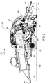
FIG. 2 is a schematic cut-away side view of a baler implement. -
FIG. 3 is a schematic fragmentary cross-sectional side view of the baler implement showing a first implementation of a lower passage wall in an operating position. -
FIG. 4 is a schematic fragmentary cross-sectional side view of the baler implement showing the first implementation of the lower passage wall in an access position. -
Fig. 5 is a schematic perspective view of the first implementation of the lower passage wall in the access position. -
FIG. 6 is a schematic fragmentary cross-sectional side view of the baler implement showing a second implementation of the lower passage wall in the operating position. -
FIG. 7 is a schematic fragmentary cross-sectional side view of the baler implement showing a third implementation of the lower passage wall in the operating position. -
FIG. 8 is a schematic fragmentary cross-sectional side view of the baler implement showing the third implementation of the lower passage wall in the access position. - Those having ordinary skill in the art will recognize that terms such as "above," "below," "upward," "downward," "top," "bottom," etc., are used descriptively for the figures, and do not represent limitations on the scope of the disclosure, as defined by the appended claims. Furthermore, the teachings may be described herein in terms of functional and/or logical block components and/or various processing steps. It should be realized that such block components may be comprised of any number of hardware, software, and/or firmware components configured to perform the specified functions.
- Terms of degree, such as "generally", "substantially" or "approximately" are understood by those of ordinary skill to refer to reasonable ranges outside of a given value or orientation, for example, general tolerances or positional relationships associated with manufacturing, assembly, and use of the described embodiments.
- Referring to the Figures, wherein like numerals indicate like parts throughout the several views, a baler implement is generally shown at 20. Referring to
FIG. 1 the baler implement 20 is shown as a large square baler. However, it should be appreciated that the teachings of this disclosure may be applied to other baler platforms, and are not limited to the example implementation of the large square baler shown in the Figures and described herein. - As shown in
FIG. 1 , a vehicle, such as but not limited to atractor 22, is coupled to the baler implement 20 for pulling and powering the baler implement 20. However, it should be appreciated that in other implementations, the baler implement 20 may be self-propelled. As depicted inFIG. 1 , the baler implement 20 may move across a field and gather and process crop material to form abale 24. The baler implement 20 may then eject the formedbale 24 from the rear of the baler implement 20. In the example implementation shown in the Figures and described herein, the baler implement 20 is configured to form thebale 24 to include a parallelepiped shape, which is often referred to as a largesquare bale 24. However, it should be appreciated that the baler implement 20 may be configured differently to form thebale 24 to exhibit a different shape. - Referring to
FIG. 2 , the example implementation of the baler implement 20 includes aframe 26,ground engaging elements 28, such as but not limited to wheels or tracks, ahitch 30 for attachment to thetractor 22 or other vehicle, and aninput shaft 32, such as a power-take-off (PTO) shaft, which can receive rotational power from a power source, such as thetractor 22. The baler implement 20 includes a pick-up 34 which gathers crop material from theground surface 102 and feeds it into the baler implement 20. The pick-up 34 mechanism may include various pick-up 34 apparatus including, but not limited to, tines,forks 74, augers, conveyors, baffles, acutter assembly 36, or any combination of the preceding. The baler implement 20 includes ahousing 38 or body, which generally shields various internal components of the baler implement 20. Thehousing 38 includes multiple wall sections that form acompression chamber 40 configured for forming the crop material into thebale 24. Thehousing 38, which forms thecompression chamber 40, extends along a centrallongitudinal axis 42. The centrallongitudinal axis 42 extends between aforward end 44 of theframe 26 orhousing 38, and arearward end 46 of theframe 26 orhousing 38. As used herein, the term forward and rearward may be interpreted with respect to the direction oftravel 48 of the baler implement 20 while gathering crop material. - The
input shaft 32 or PTO shaft is connected to an input of atransmission 50 to provide rotational power to the baler implement 20 from thetractor 22 or other associated vehicle or power source. Thetransmission 50 includes a gearbox which converts the rotational motion of theinput shaft 32 along the centrallongitudinal axis 42 of the baler implement 20 to an output of thetransmission 50 having a rotational motion along a generally transverse axis of the baler implement 20. As used herein, the term "transverse" may be interpreted as extending perpendicular to the centrallongitudinal axis 42 of the baler implement 20, between a left side and a right side of the baler implement 20 relative to the direction oftravel 48 of the baler implement 20 while gathering crop material. - The baler implement 20 includes a
crank arm 52 connected to the output of thetransmission 50. A connectinglink 54 interconnects thecrank arm 52 and aplunger 56. Thecrank arm 52 rotates based upon the output of thetransmission 50 and theplunger 56 moves in a reciprocal motion within thecompression chamber 40 as thecrank arm 52 rotates. Theplunger 56 extends into thecompression chamber 40, thereby compressing the crop material, and then at least partially retracts from thecompression chamber 40 to allow more crop material to enter thecompression chamber 40. - As described above, the
housing 38 includes multiple wall sections that form thecompression chamber 40. As such, thehousing 38 includes abottom wall 58 that partially defines a lower boundary of thecompression chamber 40. Thebottom wall 58 defines achamber inlet 60, which provides access for moving the crop material into thecompression chamber 40. - A
pre-compression passageway 62 interconnects the pick-up 34 and thechamber inlet 60. In the example implementation shown in the Figures and described herein, thepre-compression passageway 62 is defined and/or bounded by alower passage wall 64 and anupper passage wall 66. While not shown in the Figures, it should be appreciated that thepre-compression passageway 62 may further be defined by and/or bounded by a first or left lateral side wall and a second or right lateral side wall. Thepre-compression passageway 62 is a generally closed passage having aninlet 68 adjacent to the pick-up 34 for receiving the crop material, and anoutlet 70 adjacent thechamber inlet 60 for discharging the crop material through thechamber inlet 60 and into thecompression chamber 40. Thepre-compression passageway 62 forms a generally arcuate path for moving the crop material rearward and upward relative to the direction oftravel 48 of the baler implement 20. - A
feed system 72 includes a plurality offorks 74 for moving the crop material through thepre-compression passageway 62 and into the baling chamber. Theforks 74 are drivenly coupled to thetransmission 50 and are timed with theplunger 56 to move the crop material into the baling chamber when theplunger 56 is retracted. In operation, theforks 74 are staged in an initial or starting position, are inserted into thepre-compression passageway 62 and sweep rearward and upward, pushing the crop material nearer and then into thechamber inlet 60, whereupon theforks 74 are withdrawn from thepre-compression passageway 62 and returned to the initial or starting position for the subsequent cycle. - Referring to
FIGS. 3-5 , thelower passage wall 64 defines a lower and rearward boundary of thepre-compression passageway 62. Thelower passage wall 64 includes aforward portion 76, anaccess panel 78, and arearward portion 80. Theforward portion 76 is positioned proximate the pick-up 34. Theaccess panel 78 is positioned immediately rearward of theforward portion 76. Therearward portion 80 is positioned behind and above theaccess panel 78 relative to the direction oftravel 48 of the baler implement 20. Therearward portion 80 is positioned proximate thechamber inlet 60, with theaccess panel 78 positioned between theforward portion 76 and therearward portion 80 along the centrallongitudinal axis 42. - The
access panel 78 is moveable between an operating position and an access position. When theaccess panel 78 is disposed in the operating position, theaccess panel 78 is positioned relative to theforward portion 76 and therearward portion 80 to guide the crop material from the pick-up 34 to thechamber inlet 60. When theaccess panel 78 is disposed in the access position, theaccess panel 78 is positioned relative to theforward portion 76 and therearward portion 80 to provide access to thepre-compression passageway 62 through anopening 82. As such, when disposed in the access position, theaccess panel 78 is moved relative to theforward portion 76 and therearward portion 80 to expose theopening 82 into thepre-compression passageway 62. - The
access panel 78 includes a firsttransverse edge 84 and a secondtransverse edge 86. The firsttransverse edge 84 is positioned forward of the secondtransverse edge 86 relative to theforward end 44 of thehousing 38. When theaccess panel 78 is disposed in the operating position, the firsttransverse edge 84 is positioned vertically below the secondtransverse edge 86 relative to an elevation of thebottom wall 58 of thehousing 38. - In the example implementations shown in the Figures and described herein, the first
transverse edge 84 of theaccess panel 78 defines anexterior lip 88. A reartransverse edge 90 of the first portion of thelower passage wall 64 defines aninterior lip 92. Theinterior lip 92 of theforward portion 76 is positioned inward of theexterior lip 88 of theaccess panel 78 relative to thepre-compression passageway 62. - In the example implementations shown in the Figures and described herein, the
access panel 78 is attached to theforward portion 76 by apivotable connection 94. While the example implementations show thepivotable connection 94 interconnecting theforward portion 76 and theaccess panel 78, it should be appreciated that thepivotable connection 94 may attach theaccess panel 78 to some other portion or structure of the baler implement 20. Thepivotable connection 94 is disposed proximate the firsttransverse edge 84 of theaccess panel 78 such that the secondtransverse edge 86 of theaccess panel 78 moves vertically relative to the elevation of thebottom wall 58 as theaccess panel 78 moves between the operating position and the access position. By positioning thepivotable connection 94, which attaches theaccess panel 78 to the baler implement 20, near the firsttransverse edge 84 of theaccess panel 78, the secondtransverse edge 86, i.e., the rearward edge, of theaccess panel 78 moves or rotates downward and away from theupper passage wall 66. This movement provides access into thepre-compression passageway 62 from the rear of the baler implement 20 and between the secondtransverse edge 86 of theaccess panel 78 and thebottom wall 58 of thehousing 38. By moving theaccess panel 78 into the access position in the above described manner, an operator may gain access into thepre-compression passageway 62 without theaccess panel 78 hanging down from thebottom wall 58 of thehousing 38 and partially blocking theopening 82 into thepre-compression passageway 62. - Referring to
FIGS. 3-5 , a first implementation of thelower passage wall 64 is generally shown. The first implementation of thelower passage wall 64 includes thepivotable connection 94 having a linkage system. The linkage system includes thepivotable connection 94, apivot link 96, and a secondpivotal connection 98. The secondpivotable connection 94 is positioned rearward of thepivotable connection 94, relative to the centrallongitudinal axis 42, and interconnects theaccess panel 78 and thepivot link 96. Thepivot link 96 is further attached to the pivotal connection. As such, thepivot link 96 interconnects thepivotable connection 94 and the secondpivotable connection 94. - The second
pivotable connection 94 is positioned rearward of the pivotable connection 94 alink distance 100 relative to theforward end 44 of thehousing 38. Thelink distance 100 may be defined to equal a distance that approximates a distance between thepivotable connection 94 and theground surface 102, such that when theaccess panel 78 is disposed in the access position, theaccess panel 78 substantially rests flat on theground surface 102. - A
forward latch 104 may be positioned proximate the firsttransverse edge 84 of theaccess panel 78. Theforward latch 104 may interconnect theaccess panel 78 and a component of the baler implement 20, such as thehousing 38, the first lateral side wall, or the second lateral side wall. When theaccess panel 78 is disposed in the operating position, theforward latch 104 is operable to secure theaccess panel 78 to thehousing 38, with theinterior lip 92 of theforward portion 76 and theexterior lip 88 of theaccess panel 78 disposed in overlapping and/or interlocking engagement. - The
forward latch 104 may include a latch system that is selectively controllable between a latched position and an un-latched position. Theforward latch 104 may be manually operable, or may be remotely operable via a controller and/or a control signal. For example, theforward latch 104 may include an overcenter lever actuated latch system that is manually operated, an electrically actuated latch linear latch, or some other similar and/or equivalent latch system. The specific type, structure, feature, and operation of theforward latch 104 are not pertinent to the teachings of this disclosure, are appreciated by those skilled in the art, and are therefor not described in greater detail herein. - The
rearward portion 80 of thelower passage wall 64 includes a lowertransverse edge 106 and an uppertransverse edge 108. When theaccess panel 78 is disposed in the operating position, the lowertransverse edge 106 is positioned adjacent the second traverse edge of theaccess panel 78. The uppertransverse edge 108 is positioned adjacent to thebottom wall 58 of thehousing 38 and proximate to thechamber inlet 60. - Referring to
FIGS. 3-5 , the first implementation of thelower passage wall 64 includes the uppertransverse edge 108 of therearward portion 80 rotatably attached to thehousing 38 or some other component of the baler implement 20 for rotational movement about apivot location 110 relative to thehousing 38. As such, therearward portion 80 is rotatable fore and aft relative to thehousing 38. - When the
access panel 78 is positioned in the operating position, the lowertransverse edge 106 of therearward portion 80 and the secondtransverse edge 86 of theaccess panel 78 are disposed in interlocking engagement. In the example implementation shown inFIGS. 3-5 , the secondtransverse edge 86 of theaccess panel 78 defines aninner lip 112 and the lowertransverse edge 106 of therearward portion 80 defines anouter lip 114. Theinner lip 112 of theaccess panel 78 is positioned inward of theouter lip 114 of therearward portion 80 relative to thepre-compression passageway 62. - The first implementation of the
lower passage wall 64 shown inFIGS. 3-5 includes arearward latch 116. Therearward latch 116 may interconnect therearward portion 80 and a component of the baler implement 20, such as thehousing 38, the first lateral side wall, or the second lateral side wall. When theaccess panel 78 is disposed in the operating position, therearward latch 116 is operable to secure therearward portion 80 relative to thehousing 38, with theinner lip 112 of theaccess panel 78 and theouter lip 114 of the portion disposed in overlapping and/or interlocking engagement. - The
rearward latch 116 may include a latch system that is selectively controllable between a latched position and an un-latched position. Therearward latch 116 may be manually operable, or may be remotely operable via a controller and/or a control signal. For example, therearward latch 116 may include an overcenter lever actuated latch system that is manually operated, an electrically actuated latch linear latch, or some other similar and/or equivalent latch system. The specific type, structure, feature, and operation of therearward latch 116 are not pertinent to the teachings of this disclosure, are appreciated by those skilled in the art, and are therefore not described in greater detail herein. - Referring to
FIG. 6 , a second implementation of thelower passage wall 64 is generally shown. The second implementation of thelower passage wall 64 shown inFIG. 6 is similar to the first implementation of thelower passage wall 64 ofFIGS. 3-5 . The second implementation of thelower passage wall 64 shown inFIG. 6 differs in that therearward portion 80 of thelower passage wall 64 is fixedly and non-rotatably attached to thehousing 38 or some other component of the baler implement 20. Because therearward portion 80 is not rotatable relative to thehousing 38, therearward latch 116 is not required to secure the position of therearward portion 80 in the operation position. - Referring to
FIGS. 7-8 , a third implementation of thelower passage wall 64 is generally shown. The third implementation of thelower passage wall 64 shown inFIGS. 7-8 is similar to the first implementation of thelower passage wall 64 ofFIGS. 3-5 . The third implementation of thelower passage wall 64 shown inFIGS. 7-8 differs in that thepivotable connection 94 directly attaches theaccess panel 78 to theforward portion 76 of thelower passage wall 64. As such, the third implementation of thelower passage wall 64 does not include thepivot link 96 and the secondpivotal connection 98 shown in the first implementation ofFIGS. 3-5 . - As used herein, "e.g." is utilized to non-exhaustively list examples, and carries the same meaning as alternative illustrative phrases such as "including," "including, but not limited to," and "including without limitation." As used herein, unless otherwise limited or modified, lists with elements that are separated by conjunctive terms (e.g., "and") and that are also preceded by the phrase "one or more of," "at least one of," "at least," or a like phrase, indicate configurations or arrangements that potentially include individual elements of the list, or any combination thereof. For example, "at least one of A, B, and C" and "one or more of A, B, and C" each indicate the possibility of only A, only B, only C, or any combination of two or more of A, B, and C (A and B; A and C; B and C; or A, B, and C). As used herein, the singular forms "a", "an" and "the" are intended to include the plural forms as well, unless the context clearly indicates otherwise. Further, "comprises," "includes," and like phrases are intended to specify the presence of stated features, steps, operations, elements, and/or components, but do not preclude the presence or addition of one or more other features, steps, operations, elements, components, and/or groups thereof.
- The detailed description and the drawings or figures are supportive and descriptive of the disclosure, but the scope of the disclosure is defined solely by the claims. While some of the best modes and other embodiments for carrying out the claimed teachings have been described in detail, various alternative designs and embodiments exist for practicing the disclosure defined in the appended claims.
Claims (15)
- A baler implement comprising:a pick-up (34) operable to gather and move crop material;a housing (38) extending along a central longitudinal axis (42) between a forward end (44) and a rearward end (46), the housing (38) including a bottom wall (58) partially defining a compression chamber (40), the bottom wall (58) defining a chamber inlet (60);a lower passage wall (64) defining a lower boundary of a pre-compression passageway (62) interconnecting the pick-up and the chamber inlet (60), the lower passage wall (64) including an access panel (78) moveable between an operating position for guiding crop material from the pick-up (34) to the chamber inlet (60) and an access position for providing access to the pre-compression passageway (62);wherein the access panel (78) includes a first transverse edge (84) and a second transverse edge (86), with the first transverse edge (84) positioned forward of the second transverse edge (86) relative to the forward end (44) of the housing (38), and with the first transverse edge (84) positioned vertically below the second transverse edge (86) relative to an elevation of the bottom wall (58) of the housing (38) when the access panel (78) is disposed in the operating position; anda pivotable connection (94) supporting the access panel (78) and configured such that the second transverse edge (86) of the access panel (78) moves vertically relative to the elevation of the bottom wall (58) as the access panel (78) moves between the operating position and the access position to provide access into the pre-compression passageway (62).
- The baler implement set forth in claim 1, wherein the pivotable connection (94) is disposed proximate the first transverse edge (84) of the access panel (78).
- The baler implement set forth in claim 1 or 2, wherein the lower passage wall (64) includes a forward portion (76) positioned proximate the pick-up.
- The baler implement according to at least one of the claims 1 to 3, wherein the lower passage wall (64) includes a rearward portion (80) positioned proximate the chamber inlet (60), with the access panel (78) positioned between the forward portion (76) and the rearward portion (80) along the central longitudinal axis (42).
- The baler implement according to at least one of the claims 1 to 4, wherein the rearward portion (80) of the lower passage wall (64) includes a lower transverse edge (106) positioned adjacent the second transverse edge (86) of the access panel (78) when the access panel (78) is disposed in the operating position, and an upper transverse edge (108) positioned adjacent to the bottom wall (58) and proximate to the chamber inlet (60).
- The baler implement according to at least one of the claims 1 to 5, wherein the lower transverse edge (106) of the rearward portion (80) and the second transverse edge (86) of the access panel (78) are disposed in interlocking engagement when the access panel (78) is positioned in the operating position.
- The baler implement according to at least one of the claims 1 to 6, wherein the second transverse edge (86) of the access panel (78) defines an inner lip (112) and the lower transverse edge (106) of the rearward portion (80) defines an outer lip (114), with the inner lip (112) positioned inward of the outer lip (114) relative to the pre-compression passageway (62).
- The baler implement according to at least one of the claims 1 to 7, wherein the upper transverse edge (108) of the rearward portion (80) is rotatably attached to the housing (38) for rotational movement relative to the housing (38).
- The baler implement according to at least one of the claims 1 to 8, wherein the rearward portion (80) is non-moveable relative to the housing (38).
- The baler implement according to at least one of the claims 1 to 9, further comprising a rearward latch (116) interconnecting the rearward portion (80) of the lower passage wall (64) and the housing (38), with the rearward latch (116) operable to secure the rearward portion (80) relative to the housing (38) when the access panel (78) is disposed in the operating position.
- The baler implement according to at least one of the claims 1 to 10, wherein the first transverse edge (84) of the access panel (78) defines an exterior lip (88) and a rear transverse edge of the first portion defines an interior lip (92), with the interior lip (92) positioned inward of the exterior lip (99) relative to the pre-compression passageway (62).
- The baler implement according to at least one of the claims 1 to 11, further comprising a forward latch 104 positioned proximate the first transverse edge (84) of the access panel (78) and interconnecting the access panel (78) and the housing (38), with the forward latch (104) operable to secure the access panel (78) to the housing (38) when the access panel (78) is disposed in the operating position.
- The baler implement according to at least one of the claims 1 to 12, wherein the pivotable connection (94) includes a pivot link (96) interconnecting the pivotable connection (94) and the access panel (78).
- The baler implement according to at least one of the claims 1 to 13, further comprising a second pivotable connection (98) positioned rearward of the pivotable connection (94) relative to the central longitudinal axis (42) a link distance (100), wherein the second pivotable connection (98) interconnects the pivot link (96) and the access panel (78).
- The baler implement according to at least one of the claims 1 to 14, wherein the second pivotable connection (98) is spaced rearward of the pivotable connection (94) a link distance (100) relative to the forward end of the housing (38).
Applications Claiming Priority (1)
| Application Number | Priority Date | Filing Date | Title |
|---|---|---|---|
| US16/917,017 US11382277B2 (en) | 2020-06-30 | 2020-06-30 | Large square baler with pre-compression chamber having removeable access panel |
Publications (2)
| Publication Number | Publication Date |
|---|---|
| EP3932179A1 true EP3932179A1 (en) | 2022-01-05 |
| EP3932179B1 EP3932179B1 (en) | 2025-05-21 |
Family
ID=76444302
Family Applications (1)
| Application Number | Title | Priority Date | Filing Date |
|---|---|---|---|
| EP21179210.6A Active EP3932179B1 (en) | 2020-06-30 | 2021-06-14 | Large square baler with pre-compression chamber having removeable access panel |
Country Status (2)
| Country | Link |
|---|---|
| US (1) | US11382277B2 (en) |
| EP (1) | EP3932179B1 (en) |
Cited By (1)
| Publication number | Priority date | Publication date | Assignee | Title |
|---|---|---|---|---|
| US20210337737A1 (en) * | 2020-04-29 | 2021-11-04 | Maschinenfabrik Bernard Krone GmbH & Co. KG | Conveying and Collecting Device with a Drivable Conveying and Collecting Unit and Agricultural Crop Press with the Conveying and Collecting Device |
Families Citing this family (1)
| Publication number | Priority date | Publication date | Assignee | Title |
|---|---|---|---|---|
| DE102021109629A1 (en) * | 2021-04-16 | 2022-10-20 | Maschinenfabrik Bernard Krone GmbH & Co. KG | Round baler with starter roller and elastically deflectable deflection element |
Citations (3)
| Publication number | Priority date | Publication date | Assignee | Title |
|---|---|---|---|---|
| US20170105353A1 (en) * | 2015-10-20 | 2017-04-20 | Cnh Industrial America Llc | Agricultural Baler and Method for Removing a Plug of Crop Material Stuck in the Feeder Duct of an Agricultural Baler |
| EP3158856A1 (en) * | 2015-10-20 | 2017-04-26 | CNH Industrial Belgium nv | Agricultural baler and method for preventing and removing a plugging in the feeder duct of an agricultural baler |
| US20180317395A1 (en) * | 2015-10-20 | 2018-11-08 | Cnh Industrial America Llc | Agricultural Baler |
Family Cites Families (2)
| Publication number | Priority date | Publication date | Assignee | Title |
|---|---|---|---|---|
| GB8810064D0 (en) * | 1988-04-28 | 1988-06-02 | Ford New Holland Nv | Agricultural baler |
| EP3662742B1 (en) * | 2018-12-03 | 2023-02-08 | CNH Industrial Belgium NV | An agricultural baler |
-
2020
- 2020-06-30 US US16/917,017 patent/US11382277B2/en active Active
-
2021
- 2021-06-14 EP EP21179210.6A patent/EP3932179B1/en active Active
Patent Citations (3)
| Publication number | Priority date | Publication date | Assignee | Title |
|---|---|---|---|---|
| US20170105353A1 (en) * | 2015-10-20 | 2017-04-20 | Cnh Industrial America Llc | Agricultural Baler and Method for Removing a Plug of Crop Material Stuck in the Feeder Duct of an Agricultural Baler |
| EP3158856A1 (en) * | 2015-10-20 | 2017-04-26 | CNH Industrial Belgium nv | Agricultural baler and method for preventing and removing a plugging in the feeder duct of an agricultural baler |
| US20180317395A1 (en) * | 2015-10-20 | 2018-11-08 | Cnh Industrial America Llc | Agricultural Baler |
Cited By (2)
| Publication number | Priority date | Publication date | Assignee | Title |
|---|---|---|---|---|
| US20210337737A1 (en) * | 2020-04-29 | 2021-11-04 | Maschinenfabrik Bernard Krone GmbH & Co. KG | Conveying and Collecting Device with a Drivable Conveying and Collecting Unit and Agricultural Crop Press with the Conveying and Collecting Device |
| US12096722B2 (en) * | 2020-04-29 | 2024-09-24 | Maschinenfabrik Bernard Krone GmbH & Co. KG | Conveying and collecting device with a drivable conveying and collecting unit and agricultural crop press with the conveying and collecting device |
Also Published As
| Publication number | Publication date |
|---|---|
| EP3932179B1 (en) | 2025-05-21 |
| US11382277B2 (en) | 2022-07-12 |
| US20210400880A1 (en) | 2021-12-30 |
Similar Documents
| Publication | Publication Date | Title |
|---|---|---|
| EP2458955B1 (en) | Biomass baler | |
| EP2458970B1 (en) | Baler density control mechanism | |
| US8490375B2 (en) | Baler collector for collecting biomass from a combine harvester | |
| EP2458958B1 (en) | Method for projecting biomass from a combine harvester | |
| US8443580B2 (en) | Baler pickup for collecting biomass from a combine harvester | |
| US8833049B2 (en) | Transfer pan and pickup assembly | |
| EP3932179B1 (en) | Large square baler with pre-compression chamber having removeable access panel | |
| EP2458959A1 (en) | Combine chopper for feeding a baler | |
| EP2458960B1 (en) | User interface with biomass deflection information | |
| US20240164254A1 (en) | Harvesting attachment with height-adjustable cross-feeding auger | |
| EP3338533A1 (en) | Baler and method of baling | |
| US9480205B2 (en) | Combined packer and stuffer means | |
| EP2458956B1 (en) | Baler tongue for collecting biomass | |
| US3367094A (en) | Baler feed mechanism | |
| WO2024100478A1 (en) | Windguard assembly for an agtricultural baler | |
| EP4677994A1 (en) | Bale ejection system for large square baler | |
| US12402569B2 (en) | Automated last bale ejection sequence for baler implement | |
| US2835101A (en) | Reciprocating auger feeder for balers | |
| US20250024789A1 (en) | Square baler implement | |
| EP4466978A1 (en) | Panel compression system for baler implement | |
| US20190364738A1 (en) | Bale ejection device and baler |
Legal Events
| Date | Code | Title | Description |
|---|---|---|---|
| PUAI | Public reference made under article 153(3) epc to a published international application that has entered the european phase |
Free format text: ORIGINAL CODE: 0009012 |
|
| STAA | Information on the status of an ep patent application or granted ep patent |
Free format text: STATUS: THE APPLICATION HAS BEEN PUBLISHED |
|
| AK | Designated contracting states |
Kind code of ref document: A1 Designated state(s): AL AT BE BG CH CY CZ DE DK EE ES FI FR GB GR HR HU IE IS IT LI LT LU LV MC MK MT NL NO PL PT RO RS SE SI SK SM TR |
|
| B565 | Issuance of search results under rule 164(2) epc |
Effective date: 20211126 |
|
| STAA | Information on the status of an ep patent application or granted ep patent |
Free format text: STATUS: REQUEST FOR EXAMINATION WAS MADE |
|
| 17P | Request for examination filed |
Effective date: 20220705 |
|
| RBV | Designated contracting states (corrected) |
Designated state(s): AL AT BE BG CH CY CZ DE DK EE ES FI FR GB GR HR HU IE IS IT LI LT LU LV MC MK MT NL NO PL PT RO RS SE SI SK SM TR |
|
| STAA | Information on the status of an ep patent application or granted ep patent |
Free format text: STATUS: EXAMINATION IS IN PROGRESS |
|
| 17Q | First examination report despatched |
Effective date: 20230508 |
|
| GRAP | Despatch of communication of intention to grant a patent |
Free format text: ORIGINAL CODE: EPIDOSNIGR1 |
|
| STAA | Information on the status of an ep patent application or granted ep patent |
Free format text: STATUS: GRANT OF PATENT IS INTENDED |
|
| INTG | Intention to grant announced |
Effective date: 20250103 |
|
| RIN1 | Information on inventor provided before grant (corrected) |
Inventor name: KRAUS, TIMOTHY J |
|
| GRAS | Grant fee paid |
Free format text: ORIGINAL CODE: EPIDOSNIGR3 |
|
| GRAA | (expected) grant |
Free format text: ORIGINAL CODE: 0009210 |
|
| STAA | Information on the status of an ep patent application or granted ep patent |
Free format text: STATUS: THE PATENT HAS BEEN GRANTED |
|
| AK | Designated contracting states |
Kind code of ref document: B1 Designated state(s): AL AT BE BG CH CY CZ DE DK EE ES FI FR GB GR HR HU IE IS IT LI LT LU LV MC MK MT NL NO PL PT RO RS SE SI SK SM TR |
|
| REG | Reference to a national code |
Ref country code: GB Ref legal event code: FG4D |
|
| REG | Reference to a national code |
Ref country code: CH Ref legal event code: EP |
|
| REG | Reference to a national code |
Ref country code: DE Ref legal event code: R096 Ref document number: 602021031016 Country of ref document: DE |
|
| REG | Reference to a national code |
Ref country code: IE Ref legal event code: FG4D |
|
| PGFP | Annual fee paid to national office [announced via postgrant information from national office to epo] |
Ref country code: DE Payment date: 20250627 Year of fee payment: 5 |
|
| PGFP | Annual fee paid to national office [announced via postgrant information from national office to epo] |
Ref country code: FR Payment date: 20250625 Year of fee payment: 5 |
|
| PGFP | Annual fee paid to national office [announced via postgrant information from national office to epo] |
Ref country code: AT Payment date: 20250721 Year of fee payment: 5 |
|
| REG | Reference to a national code |
Ref country code: NL Ref legal event code: MP Effective date: 20250521 |
|
| PG25 | Lapsed in a contracting state [announced via postgrant information from national office to epo] |
Ref country code: ES Free format text: LAPSE BECAUSE OF FAILURE TO SUBMIT A TRANSLATION OF THE DESCRIPTION OR TO PAY THE FEE WITHIN THE PRESCRIBED TIME-LIMIT Effective date: 20250521 Ref country code: FI Free format text: LAPSE BECAUSE OF FAILURE TO SUBMIT A TRANSLATION OF THE DESCRIPTION OR TO PAY THE FEE WITHIN THE PRESCRIBED TIME-LIMIT Effective date: 20250521 Ref country code: PT Free format text: LAPSE BECAUSE OF FAILURE TO SUBMIT A TRANSLATION OF THE DESCRIPTION OR TO PAY THE FEE WITHIN THE PRESCRIBED TIME-LIMIT Effective date: 20250922 |
|
| REG | Reference to a national code |
Ref country code: LT Ref legal event code: MG9D |
|
| PG25 | Lapsed in a contracting state [announced via postgrant information from national office to epo] |
Ref country code: NO Free format text: LAPSE BECAUSE OF FAILURE TO SUBMIT A TRANSLATION OF THE DESCRIPTION OR TO PAY THE FEE WITHIN THE PRESCRIBED TIME-LIMIT Effective date: 20250821 Ref country code: GR Free format text: LAPSE BECAUSE OF FAILURE TO SUBMIT A TRANSLATION OF THE DESCRIPTION OR TO PAY THE FEE WITHIN THE PRESCRIBED TIME-LIMIT Effective date: 20250822 |
|
| PG25 | Lapsed in a contracting state [announced via postgrant information from national office to epo] |
Ref country code: NL Free format text: LAPSE BECAUSE OF FAILURE TO SUBMIT A TRANSLATION OF THE DESCRIPTION OR TO PAY THE FEE WITHIN THE PRESCRIBED TIME-LIMIT Effective date: 20250521 Ref country code: PL Free format text: LAPSE BECAUSE OF FAILURE TO SUBMIT A TRANSLATION OF THE DESCRIPTION OR TO PAY THE FEE WITHIN THE PRESCRIBED TIME-LIMIT Effective date: 20250521 |
|
| PG25 | Lapsed in a contracting state [announced via postgrant information from national office to epo] |
Ref country code: BG Free format text: LAPSE BECAUSE OF FAILURE TO SUBMIT A TRANSLATION OF THE DESCRIPTION OR TO PAY THE FEE WITHIN THE PRESCRIBED TIME-LIMIT Effective date: 20250521 |
|
| PG25 | Lapsed in a contracting state [announced via postgrant information from national office to epo] |
Ref country code: HR Free format text: LAPSE BECAUSE OF FAILURE TO SUBMIT A TRANSLATION OF THE DESCRIPTION OR TO PAY THE FEE WITHIN THE PRESCRIBED TIME-LIMIT Effective date: 20250521 |
|
| PG25 | Lapsed in a contracting state [announced via postgrant information from national office to epo] |
Ref country code: RS Free format text: LAPSE BECAUSE OF FAILURE TO SUBMIT A TRANSLATION OF THE DESCRIPTION OR TO PAY THE FEE WITHIN THE PRESCRIBED TIME-LIMIT Effective date: 20250821 |
|
| PG25 | Lapsed in a contracting state [announced via postgrant information from national office to epo] |
Ref country code: IS Free format text: LAPSE BECAUSE OF FAILURE TO SUBMIT A TRANSLATION OF THE DESCRIPTION OR TO PAY THE FEE WITHIN THE PRESCRIBED TIME-LIMIT Effective date: 20250921 |
|
| PG25 | Lapsed in a contracting state [announced via postgrant information from national office to epo] |
Ref country code: LV Free format text: LAPSE BECAUSE OF FAILURE TO SUBMIT A TRANSLATION OF THE DESCRIPTION OR TO PAY THE FEE WITHIN THE PRESCRIBED TIME-LIMIT Effective date: 20250521 |
|
| REG | Reference to a national code |
Ref country code: CH Ref legal event code: W10 Free format text: ST27 STATUS EVENT CODE: U-0-0-W10-W00 (AS PROVIDED BY THE NATIONAL OFFICE) Effective date: 20251119 |
|
| REG | Reference to a national code |
Ref country code: AT Ref legal event code: MK05 Ref document number: 1795951 Country of ref document: AT Kind code of ref document: T Effective date: 20250521 |
|
| RAP4 | Party data changed (patent owner data changed or rights of a patent transferred) |
Owner name: DEERE & COMPANY |
|
| PG25 | Lapsed in a contracting state [announced via postgrant information from national office to epo] |
Ref country code: SM Free format text: LAPSE BECAUSE OF FAILURE TO SUBMIT A TRANSLATION OF THE DESCRIPTION OR TO PAY THE FEE WITHIN THE PRESCRIBED TIME-LIMIT Effective date: 20250521 Ref country code: AT Free format text: LAPSE BECAUSE OF FAILURE TO SUBMIT A TRANSLATION OF THE DESCRIPTION OR TO PAY THE FEE WITHIN THE PRESCRIBED TIME-LIMIT Effective date: 20250521 Ref country code: DK Free format text: LAPSE BECAUSE OF FAILURE TO SUBMIT A TRANSLATION OF THE DESCRIPTION OR TO PAY THE FEE WITHIN THE PRESCRIBED TIME-LIMIT Effective date: 20250521 |
|
| PG25 | Lapsed in a contracting state [announced via postgrant information from national office to epo] |
Ref country code: CZ Free format text: LAPSE BECAUSE OF FAILURE TO SUBMIT A TRANSLATION OF THE DESCRIPTION OR TO PAY THE FEE WITHIN THE PRESCRIBED TIME-LIMIT Effective date: 20250521 |
|
| PG25 | Lapsed in a contracting state [announced via postgrant information from national office to epo] |
Ref country code: EE Free format text: LAPSE BECAUSE OF FAILURE TO SUBMIT A TRANSLATION OF THE DESCRIPTION OR TO PAY THE FEE WITHIN THE PRESCRIBED TIME-LIMIT Effective date: 20250521 |
|
| PG25 | Lapsed in a contracting state [announced via postgrant information from national office to epo] |
Ref country code: RO Free format text: LAPSE BECAUSE OF FAILURE TO SUBMIT A TRANSLATION OF THE DESCRIPTION OR TO PAY THE FEE WITHIN THE PRESCRIBED TIME-LIMIT Effective date: 20250521 Ref country code: SK Free format text: LAPSE BECAUSE OF FAILURE TO SUBMIT A TRANSLATION OF THE DESCRIPTION OR TO PAY THE FEE WITHIN THE PRESCRIBED TIME-LIMIT Effective date: 20250521 |
|
| REG | Reference to a national code |
Ref country code: CH Ref legal event code: H13 Free format text: ST27 STATUS EVENT CODE: U-0-0-H10-H13 (AS PROVIDED BY THE NATIONAL OFFICE) Effective date: 20260127 |
|
| PG25 | Lapsed in a contracting state [announced via postgrant information from national office to epo] |
Ref country code: IT Free format text: LAPSE BECAUSE OF FAILURE TO SUBMIT A TRANSLATION OF THE DESCRIPTION OR TO PAY THE FEE WITHIN THE PRESCRIBED TIME-LIMIT Effective date: 20250521 |
|
| PG25 | Lapsed in a contracting state [announced via postgrant information from national office to epo] |
Ref country code: LU Free format text: LAPSE BECAUSE OF NON-PAYMENT OF DUE FEES Effective date: 20250614 |
|
| PG25 | Lapsed in a contracting state [announced via postgrant information from national office to epo] |
Ref country code: MC Free format text: LAPSE BECAUSE OF FAILURE TO SUBMIT A TRANSLATION OF THE DESCRIPTION OR TO PAY THE FEE WITHIN THE PRESCRIBED TIME-LIMIT Effective date: 20250521 |
|
| REG | Reference to a national code |
Ref country code: DE Ref legal event code: R097 Ref document number: 602021031016 Country of ref document: DE |
|
| REG | Reference to a national code |
Ref country code: BE Ref legal event code: MM Effective date: 20250630 |
|
| PLBE | No opposition filed within time limit |
Free format text: ORIGINAL CODE: 0009261 |
|
| STAA | Information on the status of an ep patent application or granted ep patent |
Free format text: STATUS: NO OPPOSITION FILED WITHIN TIME LIMIT |
|
| REG | Reference to a national code |
Ref country code: CH Ref legal event code: L10 Free format text: ST27 STATUS EVENT CODE: U-0-0-L10-L00 (AS PROVIDED BY THE NATIONAL OFFICE) Effective date: 20260402 |
|
| PG25 | Lapsed in a contracting state [announced via postgrant information from national office to epo] |
Ref country code: IE Free format text: LAPSE BECAUSE OF NON-PAYMENT OF DUE FEES Effective date: 20250614 |
|
| PG25 | Lapsed in a contracting state [announced via postgrant information from national office to epo] |
Ref country code: BE Free format text: LAPSE BECAUSE OF NON-PAYMENT OF DUE FEES Effective date: 20250630 |
|
| PG25 | Lapsed in a contracting state [announced via postgrant information from national office to epo] |
Ref country code: CH Free format text: LAPSE BECAUSE OF NON-PAYMENT OF DUE FEES Effective date: 20250630 |
|
| 26N | No opposition filed |
Effective date: 20260224 |
|
| GBPC | Gb: european patent ceased through non-payment of renewal fee |
Effective date: 20250821 |