EP3931551B1 - Tactical chemical detector - Google Patents
Tactical chemical detector Download PDFInfo
- Publication number
- EP3931551B1 EP3931551B1 EP20762141.8A EP20762141A EP3931551B1 EP 3931551 B1 EP3931551 B1 EP 3931551B1 EP 20762141 A EP20762141 A EP 20762141A EP 3931551 B1 EP3931551 B1 EP 3931551B1
- Authority
- EP
- European Patent Office
- Prior art keywords
- sensor
- opening
- optic
- sensors
- chemical detector
- Prior art date
- Legal status (The legal status is an assumption and is not a legal conclusion. Google has not performed a legal analysis and makes no representation as to the accuracy of the status listed.)
- Active
Links
Images


Classifications
-
- G—PHYSICS
- G01—MEASURING; TESTING
- G01N—INVESTIGATING OR ANALYSING MATERIALS BY DETERMINING THEIR CHEMICAL OR PHYSICAL PROPERTIES
- G01N33/00—Investigating or analysing materials by specific methods not covered by groups G01N1/00 - G01N31/00
- G01N33/0004—Gaseous mixtures, e.g. polluted air
- G01N33/0009—General constructional details of gas analysers, e.g. portable test equipment
- G01N33/0027—General constructional details of gas analysers, e.g. portable test equipment concerning the detector
- G01N33/0031—General constructional details of gas analysers, e.g. portable test equipment concerning the detector comprising two or more sensors, e.g. a sensor array
-
- G—PHYSICS
- G01—MEASURING; TESTING
- G01N—INVESTIGATING OR ANALYSING MATERIALS BY DETERMINING THEIR CHEMICAL OR PHYSICAL PROPERTIES
- G01N21/00—Investigating or analysing materials by the use of optical means, i.e. using sub-millimetre waves, infrared, visible or ultraviolet light
- G01N21/75—Systems in which material is subjected to a chemical reaction, the progress or the result of the reaction being investigated
-
- G—PHYSICS
- G01—MEASURING; TESTING
- G01N—INVESTIGATING OR ANALYSING MATERIALS BY DETERMINING THEIR CHEMICAL OR PHYSICAL PROPERTIES
- G01N31/00—Investigating or analysing non-biological materials by the use of the chemical methods specified in the subgroup; Apparatus specially adapted for such methods
- G01N31/22—Investigating or analysing non-biological materials by the use of the chemical methods specified in the subgroup; Apparatus specially adapted for such methods using chemical indicators
- G01N31/223—Investigating or analysing non-biological materials by the use of the chemical methods specified in the subgroup; Apparatus specially adapted for such methods using chemical indicators for investigating presence of specific gases or aerosols
- G01N31/225—Investigating or analysing non-biological materials by the use of the chemical methods specified in the subgroup; Apparatus specially adapted for such methods using chemical indicators for investigating presence of specific gases or aerosols for oxygen, e.g. including dissolved oxygen
-
- G—PHYSICS
- G01—MEASURING; TESTING
- G01N—INVESTIGATING OR ANALYSING MATERIALS BY DETERMINING THEIR CHEMICAL OR PHYSICAL PROPERTIES
- G01N33/00—Investigating or analysing materials by specific methods not covered by groups G01N1/00 - G01N31/00
- G01N33/0004—Gaseous mixtures, e.g. polluted air
- G01N33/0009—General constructional details of gas analysers, e.g. portable test equipment
- G01N33/0027—General constructional details of gas analysers, e.g. portable test equipment concerning the detector
- G01N33/0036—General constructional details of gas analysers, e.g. portable test equipment concerning the detector specially adapted to detect a particular component
- G01N33/004—CO or CO2
-
- G—PHYSICS
- G01—MEASURING; TESTING
- G01N—INVESTIGATING OR ANALYSING MATERIALS BY DETERMINING THEIR CHEMICAL OR PHYSICAL PROPERTIES
- G01N33/00—Investigating or analysing materials by specific methods not covered by groups G01N1/00 - G01N31/00
- G01N33/0004—Gaseous mixtures, e.g. polluted air
- G01N33/0009—General constructional details of gas analysers, e.g. portable test equipment
- G01N33/0027—General constructional details of gas analysers, e.g. portable test equipment concerning the detector
- G01N33/0036—General constructional details of gas analysers, e.g. portable test equipment concerning the detector specially adapted to detect a particular component
- G01N33/0047—Organic compounds
-
- G—PHYSICS
- G08—SIGNALLING
- G08B—SIGNALLING SYSTEMS, e.g. PERSONAL CALLING SYSTEMS; ORDER TELEGRAPHS; ALARM SYSTEMS
- G08B7/00—Signalling systems according to two or more of groups G08B3/00 - G08B6/00
- G08B7/06—Signalling systems according to two or more of groups G08B3/00 - G08B6/00 using electric transmission, e.g. involving audible and visible signalling through the use of sound and light sources
-
- B—PERFORMING OPERATIONS; TRANSPORTING
- B82—NANOTECHNOLOGY
- B82Y—SPECIFIC USES OR APPLICATIONS OF NANOSTRUCTURES; MEASUREMENT OR ANALYSIS OF NANOSTRUCTURES; MANUFACTURE OR TREATMENT OF NANOSTRUCTURES
- B82Y30/00—Nanotechnology for materials or surface science, e.g. nanocomposites
-
- G—PHYSICS
- G01—MEASURING; TESTING
- G01N—INVESTIGATING OR ANALYSING MATERIALS BY DETERMINING THEIR CHEMICAL OR PHYSICAL PROPERTIES
- G01N2201/00—Features of devices classified in G01N21/00
- G01N2201/06—Illumination; Optics
- G01N2201/061—Sources
-
- G—PHYSICS
- G01—MEASURING; TESTING
- G01N—INVESTIGATING OR ANALYSING MATERIALS BY DETERMINING THEIR CHEMICAL OR PHYSICAL PROPERTIES
- G01N2201/00—Features of devices classified in G01N21/00
- G01N2201/06—Illumination; Optics
- G01N2201/068—Optics, miscellaneous
-
- G—PHYSICS
- G01—MEASURING; TESTING
- G01N—INVESTIGATING OR ANALYSING MATERIALS BY DETERMINING THEIR CHEMICAL OR PHYSICAL PROPERTIES
- G01N27/00—Investigating or analysing materials by the use of electric, electrochemical, or magnetic means
- G01N27/02—Investigating or analysing materials by the use of electric, electrochemical, or magnetic means by investigating impedance
- G01N27/04—Investigating or analysing materials by the use of electric, electrochemical, or magnetic means by investigating impedance by investigating resistance
- G01N27/12—Investigating or analysing materials by the use of electric, electrochemical, or magnetic means by investigating impedance by investigating resistance of a solid body in dependence upon absorption of a fluid; of a solid body in dependence upon reaction with a fluid, for detecting components in the fluid
- G01N27/125—Composition of the body, e.g. the composition of its sensitive layer
- G01N27/127—Composition of the body, e.g. the composition of its sensitive layer comprising nanoparticles
Definitions
- This disclosure relates generally to detectors for particular chemicals or contaminants.
- US 2014/235493 A1 describes a multimode gas sensor platform comprising an array of electrode pairs oriented on a substrate and a plurality of detection zones, wherein at least a portion of individual electrode pairs are separately addressable.
- US 2018/364207 A1 describes a device including a light source for providing light, a sensing element and a detector wherein the sensing element includes a nanofiber, which includes at least one oxygen sensitive compound.
- US2004/101851 A1 describes nucleic acid-based optical sensors, sensor arrays, sensing systems and sensing methods for intelligent sensing and detection of unknown materials by way of real-time feedback and control of sampling conditions.
- Airborne contaminants may include toxic industrial chemicals (TICs), chemical warfare agents (CWAs), and non-traditional agents (NTAs). These contaminants can attack skin, blood, the respiratory system, and nervous system, leading to illness, incapacitation, and, with a sufficiently high dose, death. Explosive vapors represent another threat. For example, air enriched with fuel at an appropriate ratio can be ignited by firing a weapon. Confined space threats may include oxygen levels, carbon monoxide, hydrogen sulfide, and the like. Low levels of oxygen can cause asphyxiation while high levels can cause hyperoxia that causes disorientation, seizures, and nervous system damage.
- the presence of these conditions may result in proximate danger to exposed personnel, and may indicate an imminent or ongoing threat.
- the presence of certain chemicals may indicate a leak or a failure in storage or processing of the chemical.
- a handheld or wearable chemical detector may be used to detect a specific chemical or chemicals in the environment of the detector and may be configured to transmit or display information about the presence of the specific chemical or chemicals. This may provide those exposed to the chemicals an opportunity to take appropriate steps to minimize risks by carrying out measures to protect themselves, such as donning personal protective equipment (PPE).
- PPE personal protective equipment
- a tactical chemical detector shown generally at 10, comprises a sensing assembly 20 comprising a light array 24; a sensor optic 28; and a sensor array 32.
- Tactical chemical detector 10 may further comprise a power source 34 configured to selectively provide power to various components of tactical chemical detector 10, including light array 24 and sensor array 32.
- Sensing assembly 20 is disposed within a housing 36.
- Power source 34 is also disposed within housing 36 of tactical chemical detector 10.
- Sensing assembly 20 is configured to identify particular chemicals or contaminants.
- the chemicals or contaminants may be airborne chemicals or contaminants.
- tactical chemical detector 10 may be configured to generate an alert in response to the presence of the chemical or contaminant.
- Tactical chemical detector 10 may further be configured to display or transmit an indication of the alert.
- sensor array 32 may comprise a substrate 64, and substrate 64 of sensor array 32 may comprise a printed circuit board 38.
- Printed circuit board 38 may further comprise a control circuit 38.
- Control circuit 38 may be in communication with sensing assembly 20 and with sensors 58.
- Control circuit 38 may be configured to receive inputs from sensors and to determine whether particular chemicals or contaminants have been identified.
- sensor array may be configured to be removeable and replaceable by a user.
- Housing 36 has a first side 40 and a second side 44.
- housing may further comprise a ring 46, such as an elastomeric ring, extending between and connecting together first side 40 and second side 44 of housing 36.
- First side 40 of housing 36 may define a first opening 48
- second side 44 of housing 36 may define a second opening 52.
- Second opening 52 may comprise a vent 54.
- Vent 54 may be configured to allow air to be released from interior of housing 36 of tactical chemical detector 10.
- tactical chemical detector 10 may further comprise a pump 56.
- Pump 56 may be disposed in proximity to and in communication with second opening 52 of housing 36. As shown in FIG. 2 , pump 56 may be configured to pull air in to tactical chemical detector 10 through first opening 48 in housing 36 and to cause air to pass through sensing assembly 20 and to exit from housing 36 through second opening 52 of housing 36.
- a rear baffle 60 may be configured to partially enclose pump 56, thereby directing air through second opening 52 rather than allowing air to escape and remain within housing 36 of tactical chemical detector 10.
- Pump 56 may comprise a blower.
- Sensing assembly 20 is configured to sense particular chemicals or contaminants.
- Sensor array 32 may comprise a plurality of sensors 58 arranged on a substrate 64, as shown in FIG. 3 .
- Sensors 58 comprise organic conductive or semi conductive nanofiber chemical sensors.
- the nanofibers used in sensors 58 are synthesized with specific functional groups that can interact with airborne chemicals, materials, vapors, and particles.
- the nanofibers may be deposited on an interdigitated electrode to form an electrode-nanofiber array (hereinafter referred to as a "sensor"). Interaction of the nanofibers with certain airborne materials may change the electrical characteristics of sensor 58. An increase or decrease in a particular electrical characteristic, including measured current or effective resistance, of sensor 58 may occur as a result of these airborne material interactions.
- Nanofiber sensors 58 may have excellent sensitivity and selectivity, and may be suitable for miniaturized, low-power devices. Nanofiber sensors 58 may have a small area. For example, in some embodiments, each sensor may be 3 mm x 3 mm. This may allow for a high density of sensors 58 in a small instrument. Nanofibers tend to be selective to a class of compounds (e.g., amines). Sensing assembly 20 may be configured to identify specific chemicals based on the aggregate response of the sensor array 32. Detectable chemicals may each produce a unique response signature that can be matched to known and/or predetermined response signatures in a library of response signatures.
- Sensing assembly 20 may be configured to identify specific chemicals based on the aggregate response of the sensor array 32. Detectable chemicals may each produce a unique response signature that can be matched to known and/or predetermined response signatures in a library of response signatures.
- Nanofiber sensors 58 are based on organic nanofibers.
- the nanofibers may be self-assembled from building block molecules functionalized to interact specifically with certain chemicals or classes of chemicals. Once assembled, the nanofibers may be deposited onto an electrode pair to create chemiresistive sensors (i.e., sensors that signal detection of a chemical by changing electrical resistance). The change in resistance is due to a change in charge carrier density caused by electron transfer with the chemical. The interaction is non-covalent and reversible.
- Organic conductive or semiconductive nanofibers with different functional groups may have a different response to the same airborne material.
- Sensors 58 can be configured to detect a variety of airborne chemicals, including toxins, combustion by-products, and explosives.
- Non-limiting examples of suitable nanofibers can be formed by self-assembly of building block compounds such as carbazole-cornered, arylene-ethynylene tetracyclic macromolecules, indolocarbazole derivatives thereof, substituted perylene tetracarboxylic diimide molecule, substituted a 3,4,9,10-tetracarboxyl perylene molecule, and mixtures thereof.
- building block compounds such as carbazole-cornered, arylene-ethynylene tetracyclic macromolecules, indolocarbazole derivatives thereof, substituted perylene tetracarboxylic diimide molecule, substituted a 3,4,9,10-tetracarboxyl perylene molecule, and mixtures thereof.
- Sensor optic 28 is configured to generally direct light toward sensors 58 in a sufficient magnitude to activate corresponding nanofiber materials.
- Light may comprise light in the visible spectrum.
- Light array 24 is configured to provide light to each of the plurality of sensors 58.
- Light array 24 comprises a plurality of light sources 62 disposed on a substrate 66.
- Substrate 66 may comprise a printed circuit board 38.
- light sources 62 may be light emitting diodes.
- Light sources 62 may be configured to provide light of at least about 8000 lux.
- light array 24 may be generally annular in shape. Light array 24 may define an opening 70 through the center of light array 24. Light sources 62 may be distributed around opening 70. In some embodiments, first and second openings 48, 52 may be generally circular and opening 70 of light array 24 may be coaxially aligned with both first opening 48 in first side 40 of housing 36 and second opening 52 in second side 44 of housing 36.
- Sensor optic 28 may be generally annular, and may define a generally circular opening in the center 72 of sensor optic 28.
- Generally circular opening 72 of sensor optic 28 may be configured to be coaxially aligned with at least one of opening 70 in light array 24, first opening 48 in first side 40 of housing 36 and second opening 52 in second side 44 of housing 36.
- Sensor optic 28 is configured to collimate light and to direct it to the plurality of sensors 58.
- Sensor optic 28 has a collector side 80 and an emitter side 84.
- Sensor optic 28 comprises a plurality of optic elements 68 extending through sensor optic 28 from collector side 80 to emitter side 84.
- Each optic element 68 is in optical communication with one of the plurality of light sources 62.
- Each optic element 68 is configured to collect the light from light sources 62 of light array 24 on collector side 80 of sensor array and to emit the light from optic element 68 at emitter side 84 of sensor optic 28.
- optic elements 68 may be disposed around a circumference of generally circular opening 72 of sensor optic 28.
- tactical chemical detector may further comprise an array of nanofiber-based sensors combined with at least one additional sensor for ethylene oxide, carbon monoxide, oxygen, and lower explosive limit of explosive vapors (not shown).
- Nanofiber sensors 58 may not be able to accurately detect ethylene oxide, carbon monoxide, oxygen, and lower explosive limit.
- a processor (not shown) may be disposed on a printed circuit board (PCB) 120 configured to operate the at least one additional sensor.
- the processor may be configured to operate the at least one additional sensor and sensors 58.
- the processor may also be configured to operate any alerts and algorithms associated with determining the identity of chemicals present.
- a lip 88 may extend around an outer perimeter of sensor optic 28, as shown in FIG. 4A . Lip may be configured to allow sensor optic 28 to accept light array 24, thereby securing light array 24 in a position relative to sensor optic 28. Each light source 62 from light array 24 is associated with an optic element 68. Lip 88 also may also prevent air flowing through center of light array 24 and sensor optic 28 from travelling between sensor optic 28 and light array 24, instead helping to direct air through sensor optic 28 to sensor array 32.
- Emitter side 84 of sensor optic 28 may comprise at least one mixing baffle 92 as shown in FIG. 4B .
- the at least one mixing baffle 92 may be configured to divert air travelling through center of sensor optic 28, and to distribute the air to travel across the plurality of sensors 58.
- a wall 86 may extend from a perimeter of emitter side 84 of sensor optic 28 and generally orthogonal to emitter side 84, thereby enabling sensor optic 28 to surround the plurality of sensors 58 on sensor array substrate 64.
- sensor optic 28 may comprise of an optics-grade plastic such as an optics-grade polycarbonate or an optics-grade acrylic.
- the plurality of optic elements 68 may be integrally formed within sensor optic 28.
- Sensor array 32 may comprise a plurality of sensors 58 disposed on substrate 64. Each sensor 58 is associated with one of the plurality of optic elements 68, and is in optical communication with at least one light source 62. The plurality of sensors 58 may be disposed in an arrangement on substrate 64 such as, for example, in a circular arrangement. A plurality of vent openings 96 may be disposed around an outer perimeter of the sensor arrangement. In some embodiments, there may be one vent opening 96 associated with each sensor 58. In some embodiments, at least a portion of a vent opening 96 may be disposed between each sensor 58 and wall 86 of sensor optic 28. Wall 86 may direct air flowing between sensor optic 28 and sensor array 32 to exit through the plurality of vent openings 96.
- an air-permeable hydrophobic material 104 may be disposed within housing 36 and may be configured to cover first opening 48 in housing 36. Hydrophobic material 104 may be configured to reduce or prevent moisture from entering housing 36.
- a filter 100 may be disposed within housing in proximity to first opening 48 such that hydrophobic material may be disposed between filter 100 and first opening 48 of housing 36. Filter 100 may be configured to cover first opening 48 of housing 36, thereby filtering fluids entering housing 36 through first opening 48. Openings in filter 100 may be sized to allow air to pass through into tactical chemical detector 10 but to prevent particles that might foul sensors 58 from passing through.
- air may enter tactical chemical detector 10 through first opening 48 in first side 40 of housing 36, flowing first through hydrophobic material 104, then through filter 100. Air may then flow through opening 70 in center of light array 24 and through opening 72 in center of sensor optic 28. Upon reaching substrate 64 of sensor array 32, air may change directions, flowing radially outward between sensor optic 28 and sensor array 32 past the plurality of sensors 58 and toward an outer perimeter of sensor arrangement.
- the at least one mixing baffle 92 may help to direct air toward each of the plurality of sensors 58. Air may travel across sensors 58 to vent openings 96 disposed in substrate 64 of sensor array 32 along the outer perimeter of sensor arrangement. After passing through substrate 64, air may be confined by rear baffle 60, then drawn by pump 56 through vent 54 in second opening 52 of housing 36 to exit tactical chemical detector 10.
- tactical chemical detector 10 may be configured to produce a haptic alert upon the detection of a particular chemical or chemicals.
- tactical chemical detector 10 may further comprise a haptic motor 108.
- Haptic motor 108 may be in communication with control circuit 38 and, therefore, in communication with sensing assembly 20.
- control circuit 38 may send inputs to cause haptic motor 108 to activate.
- the determination that a particular chemical has been detected may be based on changes in the electrical characteristics of sensor 58.
- haptic motor may begin vibrating and may cause tactical chemical detector 10 to vibrate.
- tactical chemical detector 10 may be configured to produce an audible alert upon the detection of a particular chemical or chemicals.
- tactical chemical detector 10 may further comprise a piezoelectric element 112.
- Piezoelectric element 112 may be in communication with control circuit 38 and, therefore, in communication with sensing assembly 20.
- control circuit 38 may send inputs to cause the activation of piezoelectric element 112.
- the activation of piezoelectric element 112 may cause tactical chemical detector 10 to produce an audible alert.
- tactical chemical detector 10 may be configured to produce a visual alert upon the detection of a particular chemical or chemicals.
- tactical chemical detector 10 may further comprise at least one light source 116 and an associated printed circuit board (PCB) 120 configured to provide a visual alert.
- the at least one light source 116 and associated PCB 120 may be in communication control circuit 38 and, therefore, in communication with sensing assembly 20.
- Housing 36 may comprise at least one light alert opening 124.
- a transparent or translucent protective shroud may cover light alert opening 124.
- Each light source 116 may be disposed within housing 36 and positioned so that, when light source 116 has been activated, light may shine through light alert opening 124.
- a light guide 118 may be configured to direct light from light source 116 to light alert opening 124.
- Each of the at least one light sources 116 and associated PCBs 120 may be in communication with control circuit 38. Upon a determination by control circuit 38 that a particular chemical has been detected, control circuit 38 may send inputs to the at least one light source 116 and associated PCBs 120 that may cause the activation of the at least one light sources 116, thereby producing a visual alert. PCB may also be configured to identify detected chemicals and cause the generation of an alert to notify the user of the presence of a potential threat.
- tactical chemical detector 10 may further comprise a display panel (not shown).
- Display panel may be in communication with control circuit 38 and, therefore, in communication with sensing assembly 20.
- Display panel may be configured to display a visual alert upon the detection of a particular chemical.
- alert may remain active until it has been acknowledged.
- At least one acknowledgement button 126 may be disposed on housing 36. Activating acknowledgement button 126 may activate an activation switch 125 within housing 36 that may terminate alert.
- tactical chemical detector 10 may comprise two acknowledgement buttons 126.
- a first acknowledgement button 126 may be disposed on a first side 127 of ring 46 or on a first portion 128 of housing.
- a second acknowledgement button 126 may be disposed on a second side 129 of ring 46 or on a second portion 130 of housing 36. Either of the two acknowledgement buttons 126 may be used to turn off or deactivate alert. Having acknowledgement buttons 126 disposed in two different locations of housing may facilitate acknowledging alerts for both right- and left-handed people since either acknowledgement button 126 may be activated with either hand of a user.
- tactical chemical detector 10 may be configured to produce at least two types of alerts.
- tactical chemical detector 10 may be configured to produce both an audible and a visual alert.
- tactical chemical detector 10 may comprise haptic motor 108, piezoelectric element 112, and an alert light source 122 and associated PCB 123, and may be configured to produce a haptic alert, an audible alert, and a visual alert.
- the alerts may be produced sequentially. For example, if an alert has not been acknowledged within a predetermined amount of time, a second alert may be activated. If the second alert is not acknowledged within a predetermined amount a third alert may be activated.
- tactical chemical detector 10 may produce a haptic alert. If the haptic alert is not acknowledged within a first predetermined amount of time, tactical chemical detector 10 may then produce an audible alert. If the audible alert is not acknowledged within a second predetermined amount of time, tactical chemical detector 10 may produce a visual alert. In some embodiments, if the alert is still not acknowledged, alerts may be combined or may alternate. For example, tactical chemical detector 10 may alternate a haptic alert with an audible alert, or may combine a haptic alert with an audible alert.
- tactical chemical detector 10 may begin a second alert. For example, if tactical chemical detector 10 has detected a first particular chemical and produced a haptic alert and progressed to an audible alert, and then a second particular chemical is detected, tactical chemical detector 10 may revert to the haptic alert and begin the alert sequence all over.
- tactical chemical detector 10 may comprise a clip 132.
- Clip 132 may be fastened to or be an integral part of housing 36.
- Clip 132 may be configured to be able to be securely fastened to a strap, a belt, a pocket or other article of clothing, or other suitable location.
- Clip 132 may be configured to lock in place, thereby preventing tactical chemical detector 10 from falling off.
- Clip 132 may be secured to second side of housing 36.
- tactical chemical detector 10 may be configured to self-test. Self-testing may be conducted either based on an input received through a user interface or at a predetermined time interval or at the occurrence of a predetermined event such as tactical chemical detector 10 being turned on. In some embodiments, as part of the self-test function, tactical chemical detector 10 may be configured to indicate whether filter 100, sensor 58, or a battery (not shown) needs to be replaced, and whether the system is operating normally.
- a method 600 for detecting chemicals or contaminants comprises providing a tactical chemical detector 10 having a light source 62 configured to provide light to a plurality of sensors 58 as shown in step 605.
- Light source 62 is collimated in step 610.
- the collimated light is directed to the plurality of sensors 58.
- a fluid is pumped through the tactical chemical detector.
- Tactical chemical detector 10 is configured to cause the fluid to pass over the plurality of sensors 58 disposed within tactical chemical detector 10.
- the fluid may be air.
- Sensors 58 comprise nanofiber chemical sensors.
- a sensing assembly of tactical chemical detector 10 may comprise a plurality of mixing baffles 92 configured to direct the fluid toward each of the nanofiber chemical sensors 58.
- the fluid is directed through one of a plurality of vent openings 96 after the fluid has passed over the sensors 58.
- the method may further comprise the step 630 of providing at least one of a haptic motor 108, a piezoelectric element 112, and an alert light source 122 and associated printed circuit board 123; and causing at least one of the haptic motor 108, the piezoelectric element 112, and the alert light source 122 and associated printed circuit board 123 to generate an alert upon the detection, by the nanofiber chemical sensors, of a particular chemical.
- references to "front,” “back,” “rear,” “upward,” “downward,” “inner,” “outer,” “right,” and “left” in this description are merely used to identify the various elements as they are oriented in the FIGURES. These terms are not meant to limit the element which they describe, as the various elements may be oriented differently in various applications.
Landscapes
- Chemical & Material Sciences (AREA)
- Health & Medical Sciences (AREA)
- Life Sciences & Earth Sciences (AREA)
- Physics & Mathematics (AREA)
- Engineering & Computer Science (AREA)
- General Physics & Mathematics (AREA)
- Biochemistry (AREA)
- Analytical Chemistry (AREA)
- General Health & Medical Sciences (AREA)
- Immunology (AREA)
- Pathology (AREA)
- Combustion & Propulsion (AREA)
- Food Science & Technology (AREA)
- Medicinal Chemistry (AREA)
- Molecular Biology (AREA)
- Biophysics (AREA)
- Dispersion Chemistry (AREA)
- Emergency Medicine (AREA)
- Chemical Kinetics & Catalysis (AREA)
- Plasma & Fusion (AREA)
- Investigating Or Analysing Materials By Optical Means (AREA)
- Geophysics And Detection Of Objects (AREA)
- User Interface Of Digital Computer (AREA)
- Infusion, Injection, And Reservoir Apparatuses (AREA)
Description
- This application claims the benefit of and priority to
U.S. Provisional Patent Application No. 62/811,262, filed on February 27, 2019 - This disclosure relates generally to detectors for particular chemicals or contaminants.
-
US 2014/235493 A1 describes a multimode gas sensor platform comprising an array of electrode pairs oriented on a substrate and a plurality of detection zones, wherein at least a portion of individual electrode pairs are separately addressable. -
US 2018/364207 A1 describes a device including a light source for providing light, a sensing element and a detector wherein the sensing element includes a nanofiber, which includes at least one oxygen sensitive compound. -
US2004/101851 A1 describes nucleic acid-based optical sensors, sensor arrays, sensing systems and sensing methods for intelligent sensing and detection of unknown materials by way of real-time feedback and control of sampling conditions. - The claimed invention is defined by the independent claim. Additional embodiments are defined by the dependent claims.
-
-
FIG. 1 illustrates an exploded view of a tactical chemical detector in accordance with an embodiment; -
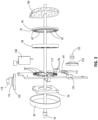
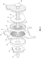
FIG. 2 illustrates an exploded view of a portion of the tactical airborne chemical detector ofFIG. 1 , and includes some of the components directed to the sensing capabilities of the device and that control airflow through the device; -
FIG. 3 illustrates a sensing assembly of an airborne chemical detector in accordance with an embodiment; -
FIG. 4A illustrates a first side of a sensor optic of an airborne chemical detector in accordance with an embodiment; -
FIG. 4B illustrates a second side of the sensor optic of an airborne chemical detector in accordance with an embodiment; and -
FIG. 5 illustrates air flow through the device ofFIG. 1 . - In some circumstances, it may be advantageous to detect specific chemicals or contaminants in the environment, and in particular, airborne contaminants. Airborne contaminants may include toxic industrial chemicals (TICs), chemical warfare agents (CWAs), and non-traditional agents (NTAs). These contaminants can attack skin, blood, the respiratory system, and nervous system, leading to illness, incapacitation, and, with a sufficiently high dose, death. Explosive vapors represent another threat. For example, air enriched with fuel at an appropriate ratio can be ignited by firing a weapon. Confined space threats may include oxygen levels, carbon monoxide, hydrogen sulfide, and the like. Low levels of oxygen can cause asphyxiation while high levels can cause hyperoxia that causes disorientation, seizures, and nervous system damage. In some embodiments, the presence of these conditions may result in proximate danger to exposed personnel, and may indicate an imminent or ongoing threat. In some circumstances, the presence of certain chemicals may indicate a leak or a failure in storage or processing of the chemical. A handheld or wearable chemical detector may be used to detect a specific chemical or chemicals in the environment of the detector and may be configured to transmit or display information about the presence of the specific chemical or chemicals. This may provide those exposed to the chemicals an opportunity to take appropriate steps to minimize risks by carrying out measures to protect themselves, such as donning personal protective equipment (PPE).
- Referring to
FIGS. 1-3 , a tactical chemical detector, shown generally at 10, comprises asensing assembly 20 comprising alight array 24; a sensor optic 28; and asensor array 32. Tacticalchemical detector 10 may further comprise apower source 34 configured to selectively provide power to various components of tacticalchemical detector 10, includinglight array 24 andsensor array 32.Sensing assembly 20 is disposed within ahousing 36.Power source 34 is also disposed withinhousing 36 of tacticalchemical detector 10. -
Sensing assembly 20 is configured to identify particular chemicals or contaminants. The chemicals or contaminants may be airborne chemicals or contaminants. In some embodiments, when a particular chemical or contaminant has been identified bysensing assembly 20, tacticalchemical detector 10 may be configured to generate an alert in response to the presence of the chemical or contaminant. Tacticalchemical detector 10 may further be configured to display or transmit an indication of the alert. - In some embodiments,
sensor array 32 may comprise asubstrate 64, andsubstrate 64 ofsensor array 32 may comprise aprinted circuit board 38. Printedcircuit board 38 may further comprise acontrol circuit 38.Control circuit 38 may be in communication withsensing assembly 20 and withsensors 58.Control circuit 38 may be configured to receive inputs from sensors and to determine whether particular chemicals or contaminants have been identified. - In some embodiments, sensor array may be configured to be removeable and replaceable by a user.
-
Housing 36 has afirst side 40 and asecond side 44. In some embodiments, housing may further comprise aring 46, such as an elastomeric ring, extending between and connecting togetherfirst side 40 andsecond side 44 ofhousing 36.First side 40 ofhousing 36 may define afirst opening 48, andsecond side 44 ofhousing 36 may define asecond opening 52.Second opening 52 may comprise avent 54. Vent 54 may be configured to allow air to be released from interior ofhousing 36 of tacticalchemical detector 10. - In some embodiments, tactical
chemical detector 10 may further comprise apump 56.Pump 56 may be disposed in proximity to and in communication withsecond opening 52 ofhousing 36. As shown inFIG. 2 ,pump 56 may be configured to pull air in to tacticalchemical detector 10 throughfirst opening 48 inhousing 36 and to cause air to pass throughsensing assembly 20 and to exit fromhousing 36 throughsecond opening 52 ofhousing 36. Arear baffle 60 may be configured to partially enclosepump 56, thereby directing air throughsecond opening 52 rather than allowing air to escape and remain withinhousing 36 of tacticalchemical detector 10.Pump 56 may comprise a blower. -
Sensing assembly 20 is configured to sense particular chemicals or contaminants.Sensor array 32 may comprise a plurality ofsensors 58 arranged on asubstrate 64, as shown inFIG. 3 .Sensors 58 comprise organic conductive or semi conductive nanofiber chemical sensors. The nanofibers used insensors 58 are synthesized with specific functional groups that can interact with airborne chemicals, materials, vapors, and particles. The nanofibers may be deposited on an interdigitated electrode to form an electrode-nanofiber array (hereinafter referred to as a "sensor"). Interaction of the nanofibers with certain airborne materials may change the electrical characteristics ofsensor 58. An increase or decrease in a particular electrical characteristic, including measured current or effective resistance, ofsensor 58 may occur as a result of these airborne material interactions. -
Nanofiber sensors 58 may have excellent sensitivity and selectivity, and may be suitable for miniaturized, low-power devices.Nanofiber sensors 58 may have a small area. For example, in some embodiments, each sensor may be 3 mm x 3 mm. This may allow for a high density ofsensors 58 in a small instrument. Nanofibers tend to be selective to a class of compounds (e.g., amines).Sensing assembly 20 may be configured to identify specific chemicals based on the aggregate response of thesensor array 32. Detectable chemicals may each produce a unique response signature that can be matched to known and/or predetermined response signatures in a library of response signatures. -
Nanofiber sensors 58 are based on organic nanofibers. The nanofibers may be self-assembled from building block molecules functionalized to interact specifically with certain chemicals or classes of chemicals. Once assembled, the nanofibers may be deposited onto an electrode pair to create chemiresistive sensors (i.e., sensors that signal detection of a chemical by changing electrical resistance). The change in resistance is due to a change in charge carrier density caused by electron transfer with the chemical. The interaction is non-covalent and reversible. - Organic conductive or semiconductive nanofibers with different functional groups may have a different response to the same airborne material. By using one or more
different sensors 58 in an array of such sensors, a response signature can be established for a particular airborne material.Sensors 58 can be configured to detect a variety of airborne chemicals, including toxins, combustion by-products, and explosives. Non-limiting examples of suitable nanofibers can be formed by self-assembly of building block compounds such as carbazole-cornered, arylene-ethynylene tetracyclic macromolecules, indolocarbazole derivatives thereof, substituted perylene tetracarboxylic diimide molecule, substituted a 3,4,9,10-tetracarboxyl perylene molecule, and mixtures thereof. - To activate sensor materials,
sensors 58 are exposed to light.Sensor optic 28 is configured to generally direct light towardsensors 58 in a sufficient magnitude to activate corresponding nanofiber materials. Light may comprise light in the visible spectrum.Light array 24 is configured to provide light to each of the plurality ofsensors 58.Light array 24 comprises a plurality oflight sources 62 disposed on asubstrate 66.Substrate 66 may comprise a printedcircuit board 38. In some embodiments,light sources 62 may be light emitting diodes.Light sources 62 may be configured to provide light of at least about 8000 lux. - In some embodiments,
light array 24 may be generally annular in shape.Light array 24 may define anopening 70 through the center oflight array 24.Light sources 62 may be distributed aroundopening 70. In some embodiments, first andsecond openings light array 24 may be coaxially aligned with bothfirst opening 48 infirst side 40 ofhousing 36 andsecond opening 52 insecond side 44 ofhousing 36. -
Sensor optic 28 may be generally annular, and may define a generally circular opening in thecenter 72 ofsensor optic 28. Generallycircular opening 72 ofsensor optic 28 may be configured to be coaxially aligned with at least one ofopening 70 inlight array 24,first opening 48 infirst side 40 ofhousing 36 andsecond opening 52 insecond side 44 ofhousing 36. -
Sensor optic 28 is configured to collimate light and to direct it to the plurality ofsensors 58.Sensor optic 28 has acollector side 80 and anemitter side 84.Sensor optic 28 comprises a plurality ofoptic elements 68 extending throughsensor optic 28 fromcollector side 80 toemitter side 84. Eachoptic element 68 is in optical communication with one of the plurality oflight sources 62. Eachoptic element 68 is configured to collect the light fromlight sources 62 oflight array 24 oncollector side 80 of sensor array and to emit the light fromoptic element 68 atemitter side 84 ofsensor optic 28. In some embodiments,optic elements 68 may be disposed around a circumference of generallycircular opening 72 ofsensor optic 28. - In some embodiments, tactical chemical detector may further comprise an array of nanofiber-based sensors combined with at least one additional sensor for ethylene oxide, carbon monoxide, oxygen, and lower explosive limit of explosive vapors (not shown).
Nanofiber sensors 58 may not be able to accurately detect ethylene oxide, carbon monoxide, oxygen, and lower explosive limit. A processor (not shown) may be disposed on a printed circuit board (PCB) 120 configured to operate the at least one additional sensor. in some embodiments, the processor may be configured to operate the at least one additional sensor andsensors 58. the processor may also be configured to operate any alerts and algorithms associated with determining the identity of chemicals present. - A
lip 88 may extend around an outer perimeter ofsensor optic 28, as shown inFIG. 4A . Lip may be configured to allowsensor optic 28 to acceptlight array 24, thereby securinglight array 24 in a position relative tosensor optic 28. Eachlight source 62 fromlight array 24 is associated with anoptic element 68.Lip 88 also may also prevent air flowing through center oflight array 24 andsensor optic 28 from travelling betweensensor optic 28 andlight array 24, instead helping to direct air throughsensor optic 28 tosensor array 32. -
Emitter side 84 ofsensor optic 28 may comprise at least one mixingbaffle 92 as shown inFIG. 4B . The at least one mixingbaffle 92 may be configured to divert air travelling through center ofsensor optic 28, and to distribute the air to travel across the plurality ofsensors 58. Awall 86 may extend from a perimeter ofemitter side 84 ofsensor optic 28 and generally orthogonal toemitter side 84, thereby enablingsensor optic 28 to surround the plurality ofsensors 58 onsensor array substrate 64. - In some embodiments,
sensor optic 28 may comprise of an optics-grade plastic such as an optics-grade polycarbonate or an optics-grade acrylic. The plurality ofoptic elements 68 may be integrally formed withinsensor optic 28. -
Sensor array 32 may comprise a plurality ofsensors 58 disposed onsubstrate 64. Eachsensor 58 is associated with one of the plurality ofoptic elements 68, and is in optical communication with at least onelight source 62. The plurality ofsensors 58 may be disposed in an arrangement onsubstrate 64 such as, for example, in a circular arrangement. A plurality ofvent openings 96 may be disposed around an outer perimeter of the sensor arrangement. In some embodiments, there may be onevent opening 96 associated with eachsensor 58. In some embodiments, at least a portion of avent opening 96 may be disposed between eachsensor 58 andwall 86 ofsensor optic 28.Wall 86 may direct air flowing betweensensor optic 28 andsensor array 32 to exit through the plurality ofvent openings 96. - In some embodiments, an air-permeable
hydrophobic material 104 may be disposed withinhousing 36 and may be configured to coverfirst opening 48 inhousing 36.Hydrophobic material 104 may be configured to reduce or prevent moisture from enteringhousing 36. Afilter 100 may be disposed within housing in proximity tofirst opening 48 such that hydrophobic material may be disposed betweenfilter 100 andfirst opening 48 ofhousing 36.Filter 100 may be configured to coverfirst opening 48 ofhousing 36, thereby filteringfluids entering housing 36 throughfirst opening 48. Openings infilter 100 may be sized to allow air to pass through intotactical chemical detector 10 but to prevent particles that might foulsensors 58 from passing through. - As shown in
FIG. 5 , whenpump 56 is operating, air may entertactical chemical detector 10 throughfirst opening 48 infirst side 40 ofhousing 36, flowing first throughhydrophobic material 104, then throughfilter 100. Air may then flow through opening 70 in center oflight array 24 and through opening 72 in center ofsensor optic 28. Upon reachingsubstrate 64 ofsensor array 32, air may change directions, flowing radially outward betweensensor optic 28 andsensor array 32 past the plurality ofsensors 58 and toward an outer perimeter of sensor arrangement. The at least one mixingbaffle 92 may help to direct air toward each of the plurality ofsensors 58. Air may travel acrosssensors 58 to ventopenings 96 disposed insubstrate 64 ofsensor array 32 along the outer perimeter of sensor arrangement. After passing throughsubstrate 64, air may be confined byrear baffle 60, then drawn bypump 56 throughvent 54 insecond opening 52 ofhousing 36 to exittactical chemical detector 10. - In some embodiments,
tactical chemical detector 10 may be configured to produce a haptic alert upon the detection of a particular chemical or chemicals. For example, in some embodiments,tactical chemical detector 10 may further comprise ahaptic motor 108.Haptic motor 108 may be in communication withcontrol circuit 38 and, therefore, in communication withsensing assembly 20. Upon a determination bycontrol circuit 38 that a particular chemical has been detected,control circuit 38 may send inputs to causehaptic motor 108 to activate. The determination that a particular chemical has been detected may be based on changes in the electrical characteristics ofsensor 58. Upon activation, haptic motor may begin vibrating and may causetactical chemical detector 10 to vibrate. - In some embodiments,
tactical chemical detector 10 may be configured to produce an audible alert upon the detection of a particular chemical or chemicals. For example, in some embodiments,tactical chemical detector 10 may further comprise apiezoelectric element 112.Piezoelectric element 112 may be in communication withcontrol circuit 38 and, therefore, in communication withsensing assembly 20. Upon a determination bycontrol circuit 38 that a particular chemical has been detected,control circuit 38 may send inputs to cause the activation ofpiezoelectric element 112. The activation ofpiezoelectric element 112 may causetactical chemical detector 10 to produce an audible alert. - In some embodiments,
tactical chemical detector 10 may be configured to produce a visual alert upon the detection of a particular chemical or chemicals. For example,tactical chemical detector 10 may further comprise at least onelight source 116 and an associated printed circuit board (PCB) 120 configured to provide a visual alert. The at least onelight source 116 and associatedPCB 120 may be incommunication control circuit 38 and, therefore, in communication withsensing assembly 20.Housing 36 may comprise at least onelight alert opening 124. A transparent or translucent protective shroud may coverlight alert opening 124. Eachlight source 116 may be disposed withinhousing 36 and positioned so that, whenlight source 116 has been activated, light may shine through lightalert opening 124. Alight guide 118 may be configured to direct light fromlight source 116 tolight alert opening 124. Each of the at least onelight sources 116 and associatedPCBs 120 may be in communication withcontrol circuit 38. Upon a determination bycontrol circuit 38 that a particular chemical has been detected,control circuit 38 may send inputs to the at least onelight source 116 and associatedPCBs 120 that may cause the activation of the at least onelight sources 116, thereby producing a visual alert. PCB may also be configured to identify detected chemicals and cause the generation of an alert to notify the user of the presence of a potential threat. - In some embodiments,
tactical chemical detector 10 may further comprise a display panel (not shown). Display panel may be in communication withcontrol circuit 38 and, therefore, in communication withsensing assembly 20. Display panel may be configured to display a visual alert upon the detection of a particular chemical. - In some embodiments, alert may remain active until it has been acknowledged. At least one
acknowledgement button 126 may be disposed onhousing 36. Activatingacknowledgement button 126 may activate anactivation switch 125 withinhousing 36 that may terminate alert. - In some embodiments,
tactical chemical detector 10 may comprise twoacknowledgement buttons 126. For example, afirst acknowledgement button 126 may be disposed on afirst side 127 ofring 46 or on afirst portion 128 of housing. Asecond acknowledgement button 126 may be disposed on asecond side 129 ofring 46 or on asecond portion 130 ofhousing 36. Either of the twoacknowledgement buttons 126 may be used to turn off or deactivate alert. Havingacknowledgement buttons 126 disposed in two different locations of housing may facilitate acknowledging alerts for both right- and left-handed people since eitheracknowledgement button 126 may be activated with either hand of a user. - In some embodiments,
tactical chemical detector 10 may be configured to produce at least two types of alerts. For example,tactical chemical detector 10 may be configured to produce both an audible and a visual alert. In some embodiments,tactical chemical detector 10 may comprisehaptic motor 108,piezoelectric element 112, and an alertlight source 122 and associatedPCB 123, and may be configured to produce a haptic alert, an audible alert, and a visual alert. In some embodiments, the alerts may be produced sequentially. For example, if an alert has not been acknowledged within a predetermined amount of time, a second alert may be activated. If the second alert is not acknowledged within a predetermined amount a third alert may be activated. For example, when a particular chemical has been detected,tactical chemical detector 10 may produce a haptic alert. If the haptic alert is not acknowledged within a first predetermined amount of time,tactical chemical detector 10 may then produce an audible alert. If the audible alert is not acknowledged within a second predetermined amount of time,tactical chemical detector 10 may produce a visual alert. In some embodiments, if the alert is still not acknowledged, alerts may be combined or may alternate. For example,tactical chemical detector 10 may alternate a haptic alert with an audible alert, or may combine a haptic alert with an audible alert. - If an alert has sounded and not yet been acknowledged, and
tactical chemical detector 10 detects a second chemical, in some embodiments,tactical chemical detector 10 may begin a second alert. For example, iftactical chemical detector 10 has detected a first particular chemical and produced a haptic alert and progressed to an audible alert, and then a second particular chemical is detected,tactical chemical detector 10 may revert to the haptic alert and begin the alert sequence all over. - In some embodiments,
tactical chemical detector 10 may comprise aclip 132.Clip 132 may be fastened to or be an integral part ofhousing 36.Clip 132 may be configured to be able to be securely fastened to a strap, a belt, a pocket or other article of clothing, or other suitable location.Clip 132 may be configured to lock in place, thereby preventingtactical chemical detector 10 from falling off.Clip 132 may be secured to second side ofhousing 36. - In some embodiments,
tactical chemical detector 10 may be configured to self-test. Self-testing may be conducted either based on an input received through a user interface or at a predetermined time interval or at the occurrence of a predetermined event such astactical chemical detector 10 being turned on. In some embodiments, as part of the self-test function,tactical chemical detector 10 may be configured to indicate whetherfilter 100,sensor 58, or a battery (not shown) needs to be replaced, and whether the system is operating normally. - Referring to
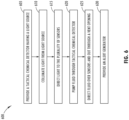
FIG. 6 , in some embodiments, amethod 600 for detecting chemicals or contaminants comprises providing atactical chemical detector 10 having alight source 62 configured to provide light to a plurality ofsensors 58 as shown instep 605.Light source 62 is collimated instep 610. Instep 615, the collimated light is directed to the plurality ofsensors 58. Instep 620, a fluid is pumped through the tactical chemical detector.Tactical chemical detector 10 is configured to cause the fluid to pass over the plurality ofsensors 58 disposed withintactical chemical detector 10. The fluid may be air.Sensors 58 comprise nanofiber chemical sensors. A sensing assembly oftactical chemical detector 10 may comprise a plurality of mixing baffles 92 configured to direct the fluid toward each of thenanofiber chemical sensors 58. Instep 625, the fluid is directed through one of a plurality ofvent openings 96 after the fluid has passed over thesensors 58. The method may further comprise thestep 630 of providing at least one of ahaptic motor 108, apiezoelectric element 112, and an alertlight source 122 and associated printedcircuit board 123; and causing at least one of thehaptic motor 108, thepiezoelectric element 112, and the alertlight source 122 and associated printedcircuit board 123 to generate an alert upon the detection, by the nanofiber chemical sensors, of a particular chemical. - The above description is considered that of the preferred embodiments only. Modifications of the disclosure will occur to those skilled in the art and to those who make or use the disclosure. Therefore, it is understood that the embodiments shown in the drawings and described above are merely for illustrative purposes and not intended to limit the scope of the invention, which is defined by the following claims.
- It should be noted that references to "front," "back," "rear," "upward," "downward," "inner," "outer," "right," and "left" in this description are merely used to identify the various elements as they are oriented in the FIGURES. These terms are not meant to limit the element which they describe, as the various elements may be oriented differently in various applications.
Claims (11)
- A sensing assembly comprising:a light array (24) comprising a plurality of light sources (62); anda sensor array (32) comprising a plurality of sensors (58) disposed on a substrate, each sensor (58) in optical communication with one of the plurality of light sources (62);wherein at least one vent opening (96) extends through the substrate of the sensor array (32);wherein the sensors are nanofiber-based chemical sensors; characterised by a sensor optic (28) comprising a plurality of optic elements, each optic element (68) in optical communication with one of the plurality of light sources (62), wherein the optic elements (68) are configured to collimate light from the light sources (62); andwherein each of the plurality of sensors (58) is in optical communication with one of the plurality of light sources (62) via at least one of the plurality of optic elements (68).
- The sensing assembly of claim 1, further comprising at least one mixing baffle (92) disposed on the sensor optic (28) and configured to direct a fluid over at least one of the plurality of sensors (58).
- The sensing assembly of one of claims 1 and 2, wherein the plurality of sensors (58) are arranged in proximity to one another on the substrate in a generally circular arrangement;wherein a plurality of vent openings (96) are disposed around an outer perimeter of the sensors; and, optionally,wherein each of the sensors (58) is associated with at least one vent opening (96).
- The sensing assembly of at least one of claims 1-3, wherein the sensor optic (28) is generally annular in shape;wherein the sensor optic (28) comprises a collector side configured to accept the light array (24) and an emitter side comprising a plurality of mixing baffles (92); andwherein a plurality of optic elements (68) extends through sensor optic (28) between collector side and emitter side.
- A tactical chemical detector (10) comprising:the sensing assembly of any one of claims 1 to 4;a power source (34) configured to selectively provide power to the light array (24) and the sensor array (32); anda housing (36) having a first side and a second side;wherein the housing encloses the light array (24), the sensor optic (28), and the sensor array (32);wherein at least a plurality of nanofibers in at least one sensor (58) have been synthesized with specific functional groups to allow the sensors (58) to interact with particular materials.
- The tactical chemical detector (10) of claim 5, further comprising a pump (56), a first opening (48) in the first side of the housing, and a second opening (52) in the second side of the housing;
wherein the pump is configured to pump fluid through into the tactical chemical detector (10) through the first opening, across the sensor array (32), and out of the tactical chemical detector (10) through the second opening. - The tactical chemical detector (10) of at least one of claims 5 or 6, further comprising a hydrophobic material (104) configured to reduce or eliminate the amount of moisture entering the tactical chemical detector (10);wherein the first side of housing defines a first opening (48); andwherein the hydrophobic material at least partially covers the first opening in the housing (36).
- The tactical chemical detector (10) of claim 7, further comprising a filter (100) disposed within the one or more housing;
wherein the filter at least partially covers the first opening. - The tactical chemical detector (10) of at least one of claims 5-8, wherein the sensor optic (28) is generally annular;wherein the sensor optic (28) defines a generally circular opening therethrough;wherein the first side of the housing defines a first opening (48);wherein the second side of the housing defines a second opening (52); andwherein the first opening, the second opening, and the opening defined through the sensor optic (28) are generally aligned with one another.
- The tactical chemical detector (10) of at least one of claims 5-9, further comprising at least one of a haptic motor, a piezoelectric element, an alerting light source, and a display panel disposed within the housing and in communication with the sensor array (32), each operable to generate an alert in the tactical chemical detector (10).
- The tactical chemical detector (10) of claim 10, further comprising at least one additional sensor (58); wherein the at least one additional sensor (58) is configured to detect at least one of oxygen levels, carbon monoxide levels, ethylene oxide, and lower explosive limits of explosive vapors.
Applications Claiming Priority (2)
| Application Number | Priority Date | Filing Date | Title |
|---|---|---|---|
| US201962811262P | 2019-02-27 | 2019-02-27 | |
| PCT/US2020/019817 WO2020176577A1 (en) | 2019-02-27 | 2020-02-26 | Tactical chemical detector |
Publications (3)
| Publication Number | Publication Date |
|---|---|
| EP3931551A1 EP3931551A1 (en) | 2022-01-05 |
| EP3931551A4 EP3931551A4 (en) | 2022-09-07 |
| EP3931551B1 true EP3931551B1 (en) | 2024-11-27 |
Family
ID=72240095
Family Applications (1)
| Application Number | Title | Priority Date | Filing Date |
|---|---|---|---|
| EP20762141.8A Active EP3931551B1 (en) | 2019-02-27 | 2020-02-26 | Tactical chemical detector |
Country Status (4)
| Country | Link |
|---|---|
| US (1) | US11175233B2 (en) |
| EP (1) | EP3931551B1 (en) |
| CN (1) | CN113614516B (en) |
| WO (1) | WO2020176577A1 (en) |
Families Citing this family (4)
| Publication number | Priority date | Publication date | Assignee | Title |
|---|---|---|---|---|
| US10241095B2 (en) | 2015-11-23 | 2019-03-26 | Sentelligence, Inc. | Multi-component gas and vapor monitoring sensor |
| US20170205338A1 (en) | 2016-01-18 | 2017-07-20 | Sentelligence, Inc. | Sensor system for multi-component fluids |
| EP4285349A4 (en) | 2021-01-29 | 2025-04-02 | Saam, Inc. | SENSOR FUSION FOR FIRE DETECTION AND AIR QUALITY MONITORING |
| USD1001663S1 (en) | 2021-12-30 | 2023-10-17 | Gentex Corporation | Chemical detector |
Family Cites Families (36)
| Publication number | Priority date | Publication date | Assignee | Title |
|---|---|---|---|---|
| JP3684970B2 (en) * | 1995-07-27 | 2005-08-17 | オムロン株式会社 | Passive detection device |
| ATE202630T1 (en) * | 1996-08-16 | 2001-07-15 | Zeptosens Ag | OPTICAL DETECTION DEVICE |
| US5796472A (en) * | 1996-09-10 | 1998-08-18 | Wirthlin; Alvin R. | Optical translucency indicator for measurement of air filter dirtiness, liquid level, thickness, and other parameters |
| US5892140A (en) * | 1997-04-30 | 1999-04-06 | Honeywell Inc. | Micromachined inferential opto-thermal gas sensor |
| GB9810350D0 (en) * | 1998-05-14 | 1998-07-15 | Ciba Geigy Ag | Organic compounds |
| AU773679B2 (en) * | 1999-07-16 | 2004-06-03 | Board Of Regents, The University Of Texas System | Method and apparatus for the delivery of samples to a chemical sensor array |
| US6876305B2 (en) * | 1999-12-08 | 2005-04-05 | Gentex Corporation | Compact particle sensor |
| US6649416B1 (en) * | 2000-02-18 | 2003-11-18 | Trustees Of Tufts College | Intelligent electro-optical sensor array and method for analyte detection |
| US6379969B1 (en) * | 2000-03-02 | 2002-04-30 | Agilent Technologies, Inc. | Optical sensor for sensing multiple analytes |
| AU2001284638A1 (en) * | 2000-05-04 | 2001-11-20 | The Johns-Hopkins University | Apparatus and methods for detecting explosives and other substances |
| ATE462122T1 (en) * | 2000-10-13 | 2010-04-15 | New A C Inc Dba Andros Inc | RESPIRATORY GAS ANALYZER |
| US7462852B2 (en) * | 2001-12-17 | 2008-12-09 | Tecomet, Inc. | Devices, methods, and systems involving cast collimators |
| US6902701B1 (en) * | 2001-10-09 | 2005-06-07 | Sandia Corporation | Apparatus for sensing volatile organic chemicals in fluids |
| US7062385B2 (en) | 2002-11-25 | 2006-06-13 | Tufts University | Intelligent electro-optical nucleic acid-based sensor array and method for detecting volatile compounds in ambient air |
| WO2004048937A2 (en) * | 2002-11-25 | 2004-06-10 | Tufts University | Electro-optical nucleic acid-based sensor array and method for detecting analytes |
| JP2006090914A (en) * | 2004-09-27 | 2006-04-06 | National Institute Of Advanced Industrial & Technology | Molecular detection device, odor sensor, optical element, molecular detection method |
| US10529003B2 (en) * | 2008-04-07 | 2020-01-07 | Mohammad A. Mazed | Optical biomodule for detection of diseases at an early onset |
| CN101387572B (en) * | 2007-09-11 | 2011-06-08 | 鸿富锦精密工业(深圳)有限公司 | Spectrum measuring fixture |
| US7659980B1 (en) * | 2008-11-24 | 2010-02-09 | Herbert Leckie Mitchell | Nephelometric turbidity sensor device |
| US8232884B2 (en) * | 2009-04-24 | 2012-07-31 | Gentex Corporation | Carbon monoxide and smoke detectors having distinct alarm indications and a test button that indicates improper operation |
| FR2951270B1 (en) | 2009-10-08 | 2012-10-26 | Centre Nat Rech Scient | OPTICAL SENSOR OF CHEMICAL SPECIES OPERATING IN INFRARED |
| WO2011123409A1 (en) * | 2010-04-02 | 2011-10-06 | 3M Innovative Properties Company | Alignment registration feature for analyte sensor optical reader |
| US20120301361A1 (en) * | 2011-05-24 | 2012-11-29 | Meadoworks, Inc. | Portable chemical detector |
| GB2493771B (en) * | 2011-08-18 | 2017-05-31 | Oxsensis Ltd | Optical sensor |
| EP2758772B1 (en) * | 2011-09-19 | 2018-10-24 | University of Utah Research Foundation | Multimode platform for detection of compounds |
| EP2623969B1 (en) * | 2012-01-31 | 2014-05-14 | Nxp B.V. | Integrated circuit and manufacturing method |
| US8872113B2 (en) * | 2012-02-21 | 2014-10-28 | Rockwell Automation Technologies, Inc. | System to test performance of pixels in a sensor array |
| WO2014037395A1 (en) * | 2012-09-04 | 2014-03-13 | Abb Technology Ag | Method for operating an electrical apparatus and electrical apparatus |
| JP6057254B2 (en) * | 2013-01-23 | 2017-01-11 | パナソニックIpマネジメント株式会社 | Infrared light receiving unit, infrared gas sensor |
| WO2015010709A1 (en) * | 2013-07-22 | 2015-01-29 | Sentec Ag | Sensor for detection of gas and method for detection of gas |
| CA2926811C (en) * | 2013-10-07 | 2023-03-21 | Google Inc. | Smart-home hazard detector providing context specific features and/or pre-alarm configurations |
| CA2959075C (en) * | 2014-08-27 | 2022-01-04 | The Commonwealth Of Australia | Methods and systems for chemical vapour sensing |
| CN205449880U (en) * | 2016-04-05 | 2016-08-10 | 深圳市诺安环境安全股份有限公司 | Ionization chamber and photoionization sensor |
| US10330617B2 (en) * | 2017-01-10 | 2019-06-25 | Design West Technologies, Inc. | Wearable sensor badge for toxic industrial chemicals |
| US10955355B2 (en) * | 2017-02-22 | 2021-03-23 | Rebellion Photonics, Inc. | Systems and methods for monitoring remote installations |
| US20180364207A1 (en) | 2017-06-15 | 2018-12-20 | Accufiber Technologies Llc | Nanofiber-based sensors and apparatus for oxygen measurement, method of making and method of using the same |
-
2020
- 2020-02-26 US US16/801,540 patent/US11175233B2/en active Active
- 2020-02-26 EP EP20762141.8A patent/EP3931551B1/en active Active
- 2020-02-26 CN CN202080023376.8A patent/CN113614516B/en active Active
- 2020-02-26 WO PCT/US2020/019817 patent/WO2020176577A1/en not_active Ceased
Also Published As
| Publication number | Publication date |
|---|---|
| US20200326286A1 (en) | 2020-10-15 |
| US11175233B2 (en) | 2021-11-16 |
| CN113614516B (en) | 2024-11-12 |
| EP3931551A1 (en) | 2022-01-05 |
| EP3931551A4 (en) | 2022-09-07 |
| CN113614516A (en) | 2021-11-05 |
| WO2020176577A1 (en) | 2020-09-03 |
Similar Documents
| Publication | Publication Date | Title |
|---|---|---|
| US11175233B2 (en) | Tactical chemical detector | |
| US10330617B2 (en) | Wearable sensor badge for toxic industrial chemicals | |
| EP3336540B1 (en) | Wearable chemical threat detector | |
| US9035243B2 (en) | Method and a device for early detection of fires | |
| AU2003302720B2 (en) | Non-specific sensor array detectors | |
| US20010050612A1 (en) | Personal alert device | |
| US11172339B1 (en) | Method and devices for detecting chemical compositions and biological pathogens | |
| US20040145485A1 (en) | Portable combustible gas detector | |
| US20170248514A1 (en) | Methods and systems for chemical vapour sensing | |
| Leonhardt | A new ppb-gas analyzer by means of GC-ion mobility spectrometry (GC-IMS) | |
| KR200495417Y1 (en) | Calibration of Nanofiber Smoke Detection | |
| US4035788A (en) | Incipient fire detector | |
| Seto et al. | Development of an on-site detection method for chemical and biological warfare agents | |
| US10935531B2 (en) | Integrated sensor packages | |
| Verma et al. | Mobile phone based explosive vapor detection system (MEDS): A methodology to save humankind | |
| CN116583886A (en) | Disaster prevention device | |
| Favas | End of service life indicator (ESLI) for respirator cartridges: Part I: Literature review | |
| JP6858614B2 (en) | Fire alarm | |
| Ng et al. | Safety and Security Applications of Sensors | |
| CN106442320A (en) | Portable explosive molecular detector | |
| JP4528603B2 (en) | Stationary gas detector | |
| US20250341487A1 (en) | Capacitance sensor for environmental detection device | |
| CN109521163B (en) | Environment detection device and method | |
| Swanson et al. | Multisensor analyzer detector (MSAD) for low cost chemical and aerosol detection and pattern fusion | |
| Elliott et al. | The civilian battlefield [transportation network security] |
Legal Events
| Date | Code | Title | Description |
|---|---|---|---|
| STAA | Information on the status of an ep patent application or granted ep patent |
Free format text: STATUS: THE INTERNATIONAL PUBLICATION HAS BEEN MADE |
|
| PUAI | Public reference made under article 153(3) epc to a published international application that has entered the european phase |
Free format text: ORIGINAL CODE: 0009012 |
|
| STAA | Information on the status of an ep patent application or granted ep patent |
Free format text: STATUS: REQUEST FOR EXAMINATION WAS MADE |
|
| 17P | Request for examination filed |
Effective date: 20210923 |
|
| AK | Designated contracting states |
Kind code of ref document: A1 Designated state(s): AL AT BE BG CH CY CZ DE DK EE ES FI FR GB GR HR HU IE IS IT LI LT LU LV MC MK MT NL NO PL PT RO RS SE SI SK SM TR |
|
| DAV | Request for validation of the european patent (deleted) | ||
| DAX | Request for extension of the european patent (deleted) | ||
| RIC1 | Information provided on ipc code assigned before grant |
Ipc: G01N 33/00 20060101ALI20220428BHEP Ipc: G01N 27/12 20060101AFI20220428BHEP |
|
| REG | Reference to a national code |
Ref country code: DE Ref legal event code: R079 Free format text: PREVIOUS MAIN CLASS: G01N0021750000 Ipc: G01N0027120000 Ref country code: DE Ref legal event code: R079 Ref document number: 602020042084 Country of ref document: DE Free format text: PREVIOUS MAIN CLASS: G01N0021750000 Ipc: G01N0027120000 |
|
| A4 | Supplementary search report drawn up and despatched |
Effective date: 20220804 |
|
| RIC1 | Information provided on ipc code assigned before grant |
Ipc: G01N 33/00 20060101ALI20220729BHEP Ipc: G01N 27/12 20060101AFI20220729BHEP |
|
| STAA | Information on the status of an ep patent application or granted ep patent |
Free format text: STATUS: EXAMINATION IS IN PROGRESS |
|
| 17Q | First examination report despatched |
Effective date: 20230213 |
|
| P01 | Opt-out of the competence of the unified patent court (upc) registered |
Effective date: 20230503 |
|
| GRAP | Despatch of communication of intention to grant a patent |
Free format text: ORIGINAL CODE: EPIDOSNIGR1 |
|
| STAA | Information on the status of an ep patent application or granted ep patent |
Free format text: STATUS: GRANT OF PATENT IS INTENDED |
|
| INTG | Intention to grant announced |
Effective date: 20240627 |
|
| GRAS | Grant fee paid |
Free format text: ORIGINAL CODE: EPIDOSNIGR3 |
|
| GRAA | (expected) grant |
Free format text: ORIGINAL CODE: 0009210 |
|
| STAA | Information on the status of an ep patent application or granted ep patent |
Free format text: STATUS: THE PATENT HAS BEEN GRANTED |
|
| AK | Designated contracting states |
Kind code of ref document: B1 Designated state(s): AL AT BE BG CH CY CZ DE DK EE ES FI FR GB GR HR HU IE IS IT LI LT LU LV MC MK MT NL NO PL PT RO RS SE SI SK SM TR |
|
| REG | Reference to a national code |
Ref country code: GB Ref legal event code: FG4D |
|
| REG | Reference to a national code |
Ref country code: CH Ref legal event code: EP |
|
| REG | Reference to a national code |
Ref country code: DE Ref legal event code: R096 Ref document number: 602020042084 Country of ref document: DE |
|
| REG | Reference to a national code |
Ref country code: IE Ref legal event code: FG4D |
|
| REG | Reference to a national code |
Ref country code: LT Ref legal event code: MG9D |
|
| REG | Reference to a national code |
Ref country code: NL Ref legal event code: MP Effective date: 20241127 |
|
| PG25 | Lapsed in a contracting state [announced via postgrant information from national office to epo] |
Ref country code: PT Free format text: LAPSE BECAUSE OF FAILURE TO SUBMIT A TRANSLATION OF THE DESCRIPTION OR TO PAY THE FEE WITHIN THE PRESCRIBED TIME-LIMIT Effective date: 20250327 Ref country code: HR Free format text: LAPSE BECAUSE OF FAILURE TO SUBMIT A TRANSLATION OF THE DESCRIPTION OR TO PAY THE FEE WITHIN THE PRESCRIBED TIME-LIMIT Effective date: 20241127 Ref country code: IS Free format text: LAPSE BECAUSE OF FAILURE TO SUBMIT A TRANSLATION OF THE DESCRIPTION OR TO PAY THE FEE WITHIN THE PRESCRIBED TIME-LIMIT Effective date: 20250327 |
|
| PG25 | Lapsed in a contracting state [announced via postgrant information from national office to epo] |
Ref country code: NL Free format text: LAPSE BECAUSE OF FAILURE TO SUBMIT A TRANSLATION OF THE DESCRIPTION OR TO PAY THE FEE WITHIN THE PRESCRIBED TIME-LIMIT Effective date: 20241127 Ref country code: FI Free format text: LAPSE BECAUSE OF FAILURE TO SUBMIT A TRANSLATION OF THE DESCRIPTION OR TO PAY THE FEE WITHIN THE PRESCRIBED TIME-LIMIT Effective date: 20241127 |
|
| REG | Reference to a national code |
Ref country code: AT Ref legal event code: MK05 Ref document number: 1746126 Country of ref document: AT Kind code of ref document: T Effective date: 20241127 |
|
| PG25 | Lapsed in a contracting state [announced via postgrant information from national office to epo] |
Ref country code: BG Free format text: LAPSE BECAUSE OF FAILURE TO SUBMIT A TRANSLATION OF THE DESCRIPTION OR TO PAY THE FEE WITHIN THE PRESCRIBED TIME-LIMIT Effective date: 20241127 |
|
| PG25 | Lapsed in a contracting state [announced via postgrant information from national office to epo] |
Ref country code: ES Free format text: LAPSE BECAUSE OF FAILURE TO SUBMIT A TRANSLATION OF THE DESCRIPTION OR TO PAY THE FEE WITHIN THE PRESCRIBED TIME-LIMIT Effective date: 20241127 |
|
| PG25 | Lapsed in a contracting state [announced via postgrant information from national office to epo] |
Ref country code: NO Free format text: LAPSE BECAUSE OF FAILURE TO SUBMIT A TRANSLATION OF THE DESCRIPTION OR TO PAY THE FEE WITHIN THE PRESCRIBED TIME-LIMIT Effective date: 20250227 |
|
| PG25 | Lapsed in a contracting state [announced via postgrant information from national office to epo] |
Ref country code: LV Free format text: LAPSE BECAUSE OF FAILURE TO SUBMIT A TRANSLATION OF THE DESCRIPTION OR TO PAY THE FEE WITHIN THE PRESCRIBED TIME-LIMIT Effective date: 20241127 Ref country code: GR Free format text: LAPSE BECAUSE OF FAILURE TO SUBMIT A TRANSLATION OF THE DESCRIPTION OR TO PAY THE FEE WITHIN THE PRESCRIBED TIME-LIMIT Effective date: 20250228 Ref country code: AT Free format text: LAPSE BECAUSE OF FAILURE TO SUBMIT A TRANSLATION OF THE DESCRIPTION OR TO PAY THE FEE WITHIN THE PRESCRIBED TIME-LIMIT Effective date: 20241127 |
|
| PG25 | Lapsed in a contracting state [announced via postgrant information from national office to epo] |
Ref country code: PL Free format text: LAPSE BECAUSE OF FAILURE TO SUBMIT A TRANSLATION OF THE DESCRIPTION OR TO PAY THE FEE WITHIN THE PRESCRIBED TIME-LIMIT Effective date: 20241127 |
|
| PG25 | Lapsed in a contracting state [announced via postgrant information from national office to epo] |
Ref country code: RS Free format text: LAPSE BECAUSE OF FAILURE TO SUBMIT A TRANSLATION OF THE DESCRIPTION OR TO PAY THE FEE WITHIN THE PRESCRIBED TIME-LIMIT Effective date: 20250227 |
|
| PG25 | Lapsed in a contracting state [announced via postgrant information from national office to epo] |
Ref country code: SM Free format text: LAPSE BECAUSE OF FAILURE TO SUBMIT A TRANSLATION OF THE DESCRIPTION OR TO PAY THE FEE WITHIN THE PRESCRIBED TIME-LIMIT Effective date: 20241127 |
|
| PG25 | Lapsed in a contracting state [announced via postgrant information from national office to epo] |
Ref country code: DK Free format text: LAPSE BECAUSE OF FAILURE TO SUBMIT A TRANSLATION OF THE DESCRIPTION OR TO PAY THE FEE WITHIN THE PRESCRIBED TIME-LIMIT Effective date: 20241127 |
|
| PG25 | Lapsed in a contracting state [announced via postgrant information from national office to epo] |
Ref country code: EE Free format text: LAPSE BECAUSE OF FAILURE TO SUBMIT A TRANSLATION OF THE DESCRIPTION OR TO PAY THE FEE WITHIN THE PRESCRIBED TIME-LIMIT Effective date: 20241127 |
|
| PG25 | Lapsed in a contracting state [announced via postgrant information from national office to epo] |
Ref country code: RO Free format text: LAPSE BECAUSE OF FAILURE TO SUBMIT A TRANSLATION OF THE DESCRIPTION OR TO PAY THE FEE WITHIN THE PRESCRIBED TIME-LIMIT Effective date: 20241127 |
|
| PG25 | Lapsed in a contracting state [announced via postgrant information from national office to epo] |
Ref country code: SK Free format text: LAPSE BECAUSE OF FAILURE TO SUBMIT A TRANSLATION OF THE DESCRIPTION OR TO PAY THE FEE WITHIN THE PRESCRIBED TIME-LIMIT Effective date: 20241127 |
|
| PG25 | Lapsed in a contracting state [announced via postgrant information from national office to epo] |
Ref country code: CZ Free format text: LAPSE BECAUSE OF FAILURE TO SUBMIT A TRANSLATION OF THE DESCRIPTION OR TO PAY THE FEE WITHIN THE PRESCRIBED TIME-LIMIT Effective date: 20241127 |
|
| PG25 | Lapsed in a contracting state [announced via postgrant information from national office to epo] |
Ref country code: IT Free format text: LAPSE BECAUSE OF FAILURE TO SUBMIT A TRANSLATION OF THE DESCRIPTION OR TO PAY THE FEE WITHIN THE PRESCRIBED TIME-LIMIT Effective date: 20241127 |
|
| REG | Reference to a national code |
Ref country code: DE Ref legal event code: R097 Ref document number: 602020042084 Country of ref document: DE |
|
| PG25 | Lapsed in a contracting state [announced via postgrant information from national office to epo] |
Ref country code: SE Free format text: LAPSE BECAUSE OF FAILURE TO SUBMIT A TRANSLATION OF THE DESCRIPTION OR TO PAY THE FEE WITHIN THE PRESCRIBED TIME-LIMIT Effective date: 20241127 |
|
| PG25 | Lapsed in a contracting state [announced via postgrant information from national office to epo] |
Ref country code: MC Free format text: LAPSE BECAUSE OF FAILURE TO SUBMIT A TRANSLATION OF THE DESCRIPTION OR TO PAY THE FEE WITHIN THE PRESCRIBED TIME-LIMIT Effective date: 20241127 |
|
| REG | Reference to a national code |
Ref country code: CH Ref legal event code: PL |
|
| PLBE | No opposition filed within time limit |
Free format text: ORIGINAL CODE: 0009261 |
|
| STAA | Information on the status of an ep patent application or granted ep patent |
Free format text: STATUS: NO OPPOSITION FILED WITHIN TIME LIMIT |
|
| PG25 | Lapsed in a contracting state [announced via postgrant information from national office to epo] |
Ref country code: LU Free format text: LAPSE BECAUSE OF NON-PAYMENT OF DUE FEES Effective date: 20250226 |
|
| PG25 | Lapsed in a contracting state [announced via postgrant information from national office to epo] |
Ref country code: CH Free format text: LAPSE BECAUSE OF NON-PAYMENT OF DUE FEES Effective date: 20250228 |
|
| 26N | No opposition filed |
Effective date: 20250828 |
|
| REG | Reference to a national code |
Ref country code: BE Ref legal event code: MM Effective date: 20250228 |
|
| PG25 | Lapsed in a contracting state [announced via postgrant information from national office to epo] |
Ref country code: BE Free format text: LAPSE BECAUSE OF NON-PAYMENT OF DUE FEES Effective date: 20250228 |
|
| PG25 | Lapsed in a contracting state [announced via postgrant information from national office to epo] |
Ref country code: IE Free format text: LAPSE BECAUSE OF NON-PAYMENT OF DUE FEES Effective date: 20250226 |
|
| PGFP | Annual fee paid to national office [announced via postgrant information from national office to epo] |
Ref country code: GB Payment date: 20260121 Year of fee payment: 7 |
|
| PGFP | Annual fee paid to national office [announced via postgrant information from national office to epo] |
Ref country code: DE Payment date: 20260121 Year of fee payment: 7 |
|
| PGFP | Annual fee paid to national office [announced via postgrant information from national office to epo] |
Ref country code: FR Payment date: 20260121 Year of fee payment: 7 |