EP3931476B1 - Centrifugal cassette with molded insertable valves - Google Patents
Centrifugal cassette with molded insertable valves Download PDFInfo
- Publication number
- EP3931476B1 EP3931476B1 EP20714766.1A EP20714766A EP3931476B1 EP 3931476 B1 EP3931476 B1 EP 3931476B1 EP 20714766 A EP20714766 A EP 20714766A EP 3931476 B1 EP3931476 B1 EP 3931476B1
- Authority
- EP
- European Patent Office
- Prior art keywords
- valve
- plate
- cassette
- valve seat
- interference seal
- Prior art date
- Legal status (The legal status is an assumption and is not a legal conclusion. Google has not performed a legal analysis and makes no representation as to the accuracy of the status listed.)
- Active
Links
Images




Classifications
-
- F—MECHANICAL ENGINEERING; LIGHTING; HEATING; WEAPONS; BLASTING
- F16—ENGINEERING ELEMENTS AND UNITS; GENERAL MEASURES FOR PRODUCING AND MAINTAINING EFFECTIVE FUNCTIONING OF MACHINES OR INSTALLATIONS; THERMAL INSULATION IN GENERAL
- F16K—VALVES; TAPS; COCKS; ACTUATING-FLOATS; DEVICES FOR VENTING OR AERATING
- F16K99/00—Subject matter not provided for in other groups of this subclass
- F16K99/0001—Microvalves
- F16K99/0003—Constructional types of microvalves; Details of the cutting-off member
- F16K99/003—Valves for single use only
-
- F—MECHANICAL ENGINEERING; LIGHTING; HEATING; WEAPONS; BLASTING
- F16—ENGINEERING ELEMENTS AND UNITS; GENERAL MEASURES FOR PRODUCING AND MAINTAINING EFFECTIVE FUNCTIONING OF MACHINES OR INSTALLATIONS; THERMAL INSULATION IN GENERAL
- F16K—VALVES; TAPS; COCKS; ACTUATING-FLOATS; DEVICES FOR VENTING OR AERATING
- F16K99/00—Subject matter not provided for in other groups of this subclass
- F16K99/0001—Microvalves
- F16K99/0003—Constructional types of microvalves; Details of the cutting-off member
- F16K99/0011—Gate valves or sliding valves
-
- A—HUMAN NECESSITIES
- A61—MEDICAL OR VETERINARY SCIENCE; HYGIENE
- A61M—DEVICES FOR INTRODUCING MEDIA INTO, OR ONTO, THE BODY; DEVICES FOR TRANSDUCING BODY MEDIA OR FOR TAKING MEDIA FROM THE BODY; DEVICES FOR PRODUCING OR ENDING SLEEP OR STUPOR
- A61M1/00—Suction or pumping devices for medical purposes; Devices for carrying-off, for treatment of, or for carrying-over, body-liquids; Drainage systems
- A61M1/02—Blood transfusion apparatus
- A61M1/029—Separating blood components present in distinct layers in a container, not otherwise provided for
-
- A—HUMAN NECESSITIES
- A61—MEDICAL OR VETERINARY SCIENCE; HYGIENE
- A61M—DEVICES FOR INTRODUCING MEDIA INTO, OR ONTO, THE BODY; DEVICES FOR TRANSDUCING BODY MEDIA OR FOR TAKING MEDIA FROM THE BODY; DEVICES FOR PRODUCING OR ENDING SLEEP OR STUPOR
- A61M1/00—Suction or pumping devices for medical purposes; Devices for carrying-off, for treatment of, or for carrying-over, body-liquids; Drainage systems
- A61M1/36—Other treatment of blood in a by-pass of the natural circulatory system, e.g. temperature adaptation, irradiation ; Extra-corporeal blood circuits
- A61M1/3621—Extra-corporeal blood circuits
- A61M1/3622—Extra-corporeal blood circuits with a cassette forming partially or totally the blood circuit
- A61M1/36226—Constructional details of cassettes, e.g. specific details on material or shape
-
- A—HUMAN NECESSITIES
- A61—MEDICAL OR VETERINARY SCIENCE; HYGIENE
- A61M—DEVICES FOR INTRODUCING MEDIA INTO, OR ONTO, THE BODY; DEVICES FOR TRANSDUCING BODY MEDIA OR FOR TAKING MEDIA FROM THE BODY; DEVICES FOR PRODUCING OR ENDING SLEEP OR STUPOR
- A61M1/00—Suction or pumping devices for medical purposes; Devices for carrying-off, for treatment of, or for carrying-over, body-liquids; Drainage systems
- A61M1/36—Other treatment of blood in a by-pass of the natural circulatory system, e.g. temperature adaptation, irradiation ; Extra-corporeal blood circuits
- A61M1/3621—Extra-corporeal blood circuits
- A61M1/3622—Extra-corporeal blood circuits with a cassette forming partially or totally the blood circuit
- A61M1/36226—Constructional details of cassettes, e.g. specific details on material or shape
- A61M1/362262—Details of incorporated reservoirs
-
- A—HUMAN NECESSITIES
- A61—MEDICAL OR VETERINARY SCIENCE; HYGIENE
- A61M—DEVICES FOR INTRODUCING MEDIA INTO, OR ONTO, THE BODY; DEVICES FOR TRANSDUCING BODY MEDIA OR FOR TAKING MEDIA FROM THE BODY; DEVICES FOR PRODUCING OR ENDING SLEEP OR STUPOR
- A61M1/00—Suction or pumping devices for medical purposes; Devices for carrying-off, for treatment of, or for carrying-over, body-liquids; Drainage systems
- A61M1/36—Other treatment of blood in a by-pass of the natural circulatory system, e.g. temperature adaptation, irradiation ; Extra-corporeal blood circuits
- A61M1/3621—Extra-corporeal blood circuits
- A61M1/3622—Extra-corporeal blood circuits with a cassette forming partially or totally the blood circuit
- A61M1/36226—Constructional details of cassettes, e.g. specific details on material or shape
- A61M1/362265—Details of valves
-
- A—HUMAN NECESSITIES
- A61—MEDICAL OR VETERINARY SCIENCE; HYGIENE
- A61M—DEVICES FOR INTRODUCING MEDIA INTO, OR ONTO, THE BODY; DEVICES FOR TRANSDUCING BODY MEDIA OR FOR TAKING MEDIA FROM THE BODY; DEVICES FOR PRODUCING OR ENDING SLEEP OR STUPOR
- A61M1/00—Suction or pumping devices for medical purposes; Devices for carrying-off, for treatment of, or for carrying-over, body-liquids; Drainage systems
- A61M1/36—Other treatment of blood in a by-pass of the natural circulatory system, e.g. temperature adaptation, irradiation ; Extra-corporeal blood circuits
- A61M1/3693—Other treatment of blood in a by-pass of the natural circulatory system, e.g. temperature adaptation, irradiation ; Extra-corporeal blood circuits using separation based on different densities of components, e.g. centrifuging
-
- B—PERFORMING OPERATIONS; TRANSPORTING
- B01—PHYSICAL OR CHEMICAL PROCESSES OR APPARATUS IN GENERAL
- B01L—CHEMICAL OR PHYSICAL LABORATORY APPARATUS FOR GENERAL USE
- B01L3/00—Containers or dishes for laboratory use, e.g. laboratory glassware; Droppers
- B01L3/50—Containers for the purpose of retaining a material to be analysed, e.g. test tubes
- B01L3/502—Containers for the purpose of retaining a material to be analysed, e.g. test tubes with fluid transport, e.g. in multi-compartment structures
- B01L3/5027—Containers for the purpose of retaining a material to be analysed, e.g. test tubes with fluid transport, e.g. in multi-compartment structures by integrated microfluidic structures, i.e. dimensions of channels and chambers are such that surface tension forces are important, e.g. lab-on-a-chip
- B01L3/502707—Containers for the purpose of retaining a material to be analysed, e.g. test tubes with fluid transport, e.g. in multi-compartment structures by integrated microfluidic structures, i.e. dimensions of channels and chambers are such that surface tension forces are important, e.g. lab-on-a-chip characterised by the manufacture of the container or its components
-
- B—PERFORMING OPERATIONS; TRANSPORTING
- B01—PHYSICAL OR CHEMICAL PROCESSES OR APPARATUS IN GENERAL
- B01L—CHEMICAL OR PHYSICAL LABORATORY APPARATUS FOR GENERAL USE
- B01L3/00—Containers or dishes for laboratory use, e.g. laboratory glassware; Droppers
- B01L3/50—Containers for the purpose of retaining a material to be analysed, e.g. test tubes
- B01L3/502—Containers for the purpose of retaining a material to be analysed, e.g. test tubes with fluid transport, e.g. in multi-compartment structures
- B01L3/5027—Containers for the purpose of retaining a material to be analysed, e.g. test tubes with fluid transport, e.g. in multi-compartment structures by integrated microfluidic structures, i.e. dimensions of channels and chambers are such that surface tension forces are important, e.g. lab-on-a-chip
- B01L3/502738—Containers for the purpose of retaining a material to be analysed, e.g. test tubes with fluid transport, e.g. in multi-compartment structures by integrated microfluidic structures, i.e. dimensions of channels and chambers are such that surface tension forces are important, e.g. lab-on-a-chip characterised by integrated valves
-
- B—PERFORMING OPERATIONS; TRANSPORTING
- B04—CENTRIFUGAL APPARATUS OR MACHINES FOR CARRYING-OUT PHYSICAL OR CHEMICAL PROCESSES
- B04B—CENTRIFUGES
- B04B5/00—Other centrifuges
- B04B5/04—Radial chamber apparatus for separating predominantly liquid mixtures, e.g. butyrometers
- B04B5/0442—Radial chamber apparatus for separating predominantly liquid mixtures, e.g. butyrometers with means for adding or withdrawing liquid substances during the centrifugation, e.g. continuous centrifugation
-
- B—PERFORMING OPERATIONS; TRANSPORTING
- B29—WORKING OF PLASTICS; WORKING OF SUBSTANCES IN A PLASTIC STATE IN GENERAL
- B29C—SHAPING OR JOINING OF PLASTICS; SHAPING OF MATERIAL IN A PLASTIC STATE, NOT OTHERWISE PROVIDED FOR; AFTER-TREATMENT OF THE SHAPED PRODUCTS, e.g. REPAIRING
- B29C45/00—Injection moulding, i.e. forcing the required volume of moulding material through a nozzle into a closed mould; Apparatus therefor
- B29C45/0053—Injection moulding, i.e. forcing the required volume of moulding material through a nozzle into a closed mould; Apparatus therefor combined with a final operation, e.g. shaping
-
- F—MECHANICAL ENGINEERING; LIGHTING; HEATING; WEAPONS; BLASTING
- F16—ENGINEERING ELEMENTS AND UNITS; GENERAL MEASURES FOR PRODUCING AND MAINTAINING EFFECTIVE FUNCTIONING OF MACHINES OR INSTALLATIONS; THERMAL INSULATION IN GENERAL
- F16K—VALVES; TAPS; COCKS; ACTUATING-FLOATS; DEVICES FOR VENTING OR AERATING
- F16K99/00—Subject matter not provided for in other groups of this subclass
- F16K99/0001—Microvalves
- F16K99/0003—Constructional types of microvalves; Details of the cutting-off member
- F16K99/0032—Constructional types of microvalves; Details of the cutting-off member using phase transition or influencing viscosity
-
- F—MECHANICAL ENGINEERING; LIGHTING; HEATING; WEAPONS; BLASTING
- F16—ENGINEERING ELEMENTS AND UNITS; GENERAL MEASURES FOR PRODUCING AND MAINTAINING EFFECTIVE FUNCTIONING OF MACHINES OR INSTALLATIONS; THERMAL INSULATION IN GENERAL
- F16K—VALVES; TAPS; COCKS; ACTUATING-FLOATS; DEVICES FOR VENTING OR AERATING
- F16K99/00—Subject matter not provided for in other groups of this subclass
- F16K99/0001—Microvalves
- F16K99/0034—Operating means specially adapted for microvalves
- F16K99/0036—Operating means specially adapted for microvalves operated by temperature variations
- F16K99/004—Operating means specially adapted for microvalves operated by temperature variations using radiation
-
- F—MECHANICAL ENGINEERING; LIGHTING; HEATING; WEAPONS; BLASTING
- F16—ENGINEERING ELEMENTS AND UNITS; GENERAL MEASURES FOR PRODUCING AND MAINTAINING EFFECTIVE FUNCTIONING OF MACHINES OR INSTALLATIONS; THERMAL INSULATION IN GENERAL
- F16K—VALVES; TAPS; COCKS; ACTUATING-FLOATS; DEVICES FOR VENTING OR AERATING
- F16K99/00—Subject matter not provided for in other groups of this subclass
- F16K99/0001—Microvalves
- F16K99/0034—Operating means specially adapted for microvalves
- F16K99/0042—Electric operating means therefor
- F16K99/0044—Electric operating means therefor using thermo-electric means
-
- F—MECHANICAL ENGINEERING; LIGHTING; HEATING; WEAPONS; BLASTING
- F16—ENGINEERING ELEMENTS AND UNITS; GENERAL MEASURES FOR PRODUCING AND MAINTAINING EFFECTIVE FUNCTIONING OF MACHINES OR INSTALLATIONS; THERMAL INSULATION IN GENERAL
- F16K—VALVES; TAPS; COCKS; ACTUATING-FLOATS; DEVICES FOR VENTING OR AERATING
- F16K99/00—Subject matter not provided for in other groups of this subclass
- F16K99/0001—Microvalves
- F16K99/0034—Operating means specially adapted for microvalves
- F16K99/0063—Operating means specially adapted for microvalves using centrifugal forces
-
- G—PHYSICS
- G01—MEASURING; TESTING
- G01N—INVESTIGATING OR ANALYSING MATERIALS BY DETERMINING THEIR CHEMICAL OR PHYSICAL PROPERTIES
- G01N33/00—Investigating or analysing materials by specific methods not covered by groups G01N1/00 - G01N31/00
- G01N33/48—Biological material, e.g. blood, urine; Haemocytometers
- G01N33/483—Physical analysis of biological material
- G01N33/487—Physical analysis of biological material of liquid biological material
- G01N33/49—Blood
- G01N33/491—Blood by separating the blood components
-
- A—HUMAN NECESSITIES
- A61—MEDICAL OR VETERINARY SCIENCE; HYGIENE
- A61M—DEVICES FOR INTRODUCING MEDIA INTO, OR ONTO, THE BODY; DEVICES FOR TRANSDUCING BODY MEDIA OR FOR TAKING MEDIA FROM THE BODY; DEVICES FOR PRODUCING OR ENDING SLEEP OR STUPOR
- A61M2205/00—General characteristics of the apparatus
- A61M2205/12—General characteristics of the apparatus with interchangeable cassettes forming partially or totally the fluid circuit
- A61M2205/128—General characteristics of the apparatus with interchangeable cassettes forming partially or totally the fluid circuit with incorporated valves
-
- A—HUMAN NECESSITIES
- A61—MEDICAL OR VETERINARY SCIENCE; HYGIENE
- A61M—DEVICES FOR INTRODUCING MEDIA INTO, OR ONTO, THE BODY; DEVICES FOR TRANSDUCING BODY MEDIA OR FOR TAKING MEDIA FROM THE BODY; DEVICES FOR PRODUCING OR ENDING SLEEP OR STUPOR
- A61M2205/00—General characteristics of the apparatus
- A61M2205/36—General characteristics of the apparatus related to heating or cooling
- A61M2205/3653—General characteristics of the apparatus related to heating or cooling by Joule effect, i.e. electric resistance
-
- B—PERFORMING OPERATIONS; TRANSPORTING
- B01—PHYSICAL OR CHEMICAL PROCESSES OR APPARATUS IN GENERAL
- B01L—CHEMICAL OR PHYSICAL LABORATORY APPARATUS FOR GENERAL USE
- B01L2300/00—Additional constructional details
- B01L2300/18—Means for temperature control
- B01L2300/1805—Conductive heating, heat from thermostatted solids is conducted to receptacles, e.g. heating plates, blocks
- B01L2300/1827—Conductive heating, heat from thermostatted solids is conducted to receptacles, e.g. heating plates, blocks using resistive heater
-
- B—PERFORMING OPERATIONS; TRANSPORTING
- B01—PHYSICAL OR CHEMICAL PROCESSES OR APPARATUS IN GENERAL
- B01L—CHEMICAL OR PHYSICAL LABORATORY APPARATUS FOR GENERAL USE
- B01L2400/00—Moving or stopping fluids
- B01L2400/06—Valves, specific forms thereof
- B01L2400/0677—Valves, specific forms thereof phase change valves; Meltable, freezing, dissolvable plugs; Destructible barriers
-
- B—PERFORMING OPERATIONS; TRANSPORTING
- B29—WORKING OF PLASTICS; WORKING OF SUBSTANCES IN A PLASTIC STATE IN GENERAL
- B29K—INDEXING SCHEME ASSOCIATED WITH SUBCLASSES B29B, B29C OR B29D, RELATING TO MOULDING MATERIALS OR TO MATERIALS FOR MOULDS, REINFORCEMENTS, FILLERS OR PREFORMED PARTS, e.g. INSERTS
- B29K2023/00—Use of polyalkenes or derivatives thereof as moulding material
- B29K2023/04—Polymers of ethylene
- B29K2023/08—Copolymers of ethylene
- B29K2023/083—EVA, i.e. ethylene vinyl acetate copolymer
-
- B—PERFORMING OPERATIONS; TRANSPORTING
- B29—WORKING OF PLASTICS; WORKING OF SUBSTANCES IN A PLASTIC STATE IN GENERAL
- B29L—INDEXING SCHEME ASSOCIATED WITH SUBCLASS B29C, RELATING TO PARTICULAR ARTICLES
- B29L2031/00—Other particular articles
- B29L2031/748—Machines or parts thereof not otherwise provided for
- B29L2031/7506—Valves
-
- F—MECHANICAL ENGINEERING; LIGHTING; HEATING; WEAPONS; BLASTING
- F16—ENGINEERING ELEMENTS AND UNITS; GENERAL MEASURES FOR PRODUCING AND MAINTAINING EFFECTIVE FUNCTIONING OF MACHINES OR INSTALLATIONS; THERMAL INSULATION IN GENERAL
- F16K—VALVES; TAPS; COCKS; ACTUATING-FLOATS; DEVICES FOR VENTING OR AERATING
- F16K99/00—Subject matter not provided for in other groups of this subclass
- F16K2099/0073—Fabrication methods specifically adapted for microvalves
- F16K2099/0078—Fabrication methods specifically adapted for microvalves using moulding or stamping
-
- F—MECHANICAL ENGINEERING; LIGHTING; HEATING; WEAPONS; BLASTING
- F16—ENGINEERING ELEMENTS AND UNITS; GENERAL MEASURES FOR PRODUCING AND MAINTAINING EFFECTIVE FUNCTIONING OF MACHINES OR INSTALLATIONS; THERMAL INSULATION IN GENERAL
- F16K—VALVES; TAPS; COCKS; ACTUATING-FLOATS; DEVICES FOR VENTING OR AERATING
- F16K99/00—Subject matter not provided for in other groups of this subclass
- F16K2099/0082—Microvalves adapted for a particular use
- F16K2099/0084—Chemistry or biology, e.g. "lab-on-a-chip" technology
-
- F—MECHANICAL ENGINEERING; LIGHTING; HEATING; WEAPONS; BLASTING
- F16—ENGINEERING ELEMENTS AND UNITS; GENERAL MEASURES FOR PRODUCING AND MAINTAINING EFFECTIVE FUNCTIONING OF MACHINES OR INSTALLATIONS; THERMAL INSULATION IN GENERAL
- F16K—VALVES; TAPS; COCKS; ACTUATING-FLOATS; DEVICES FOR VENTING OR AERATING
- F16K99/00—Subject matter not provided for in other groups of this subclass
- F16K99/0001—Microvalves
- F16K99/0034—Operating means specially adapted for microvalves
- F16K99/0036—Operating means specially adapted for microvalves operated by temperature variations
-
- G—PHYSICS
- G01—MEASURING; TESTING
- G01N—INVESTIGATING OR ANALYSING MATERIALS BY DETERMINING THEIR CHEMICAL OR PHYSICAL PROPERTIES
- G01N35/00—Automatic analysis not limited to methods or materials provided for in any single one of groups G01N1/00 - G01N33/00; Handling materials therefor
- G01N2035/00465—Separating and mixing arrangements
- G01N2035/00495—Centrifuges
Definitions
- the present application describes a centrifugal cassette including molded Normally Open Valves (NOVs) and Normally Closed Valves (NCVs).
- the centrifugal cassette is configured to allow for insertion of the valves after the cassette has been partially manufactured in a hot plate welding process.
- a centrifuge cassette or cartridge may be used to separate human or animal blood.
- the centrifuge cassette exist several fluid chambers connected by a variety of fluid channels operating together under centrifugal force to control the separation process.
- the flow of fluid in the fluid channels may be regulated by the actuation of NOVs and NCVs which typically include wax elements that are formed into the fluid channels of the centrifuge cassette during its manufacture.
- NOVs and NCVs typically include wax elements that are formed into the fluid channels of the centrifuge cassette during its manufacture.
- Embodiments of the present application have been made in view of these and other considerations. However, the relatively specific problems discussed above do not limit the applicability of the embodiments of the present application.
- US 6 102 897 discloses a microvalve for disposable use with a casing with at least one valve seat and a closing element fusible under thermal application for the opening and/or closing of the microvalve.
- US 2018/0093270 discloses a modular cassette and a method for separating a composite fluid into at least two components parts thereof during centrifugation.
- a method of manufacturing a centrifuge cassette assembly and a centrifuge cassette assembly A Normally Closed Valve (NCV) and a Normally Open Valve (NOV) for insertion into said cassette assembly are defined in the appended claims.
- a Normally Closed Valve for insertion into a fluidic channel.
- the NCV includes at least one interference seal member, at least one valve seal post, and a valve rib.
- the at least one interference seal member is configured to cooperate with at least one interference seal member of a valve seat of a fluidic channel.
- a Normally Open Valve for insertion into a fluidic channel.
- the NOV includes at least one interference seal member and a lumen.
- the at least one interference seal member is configured to cooperate with at least one interference seal member of a valve seat of fluidic channel.
- a centrifuge cassette for separating a fluid.
- the cassette includes a first chamber, a second chamber, a fluidic channel creating a fluid connection between the first chamber and the second chamber, at least one molded insertion valve configured to control the flow of fluid in the fluidic channel, and a heating element for actuating the at least one molded valve.
- a method of manufacturing a centrifuge cassette assembly includes injection molding a first plate, the first plate including an upper valve seat, injection molding a second plate, the second plate including a fluidic channel and a lower valve seat, nesting each of the first plate and the second plate in a holding fixture, heating elements of the first plate and the second plate, aligning the valve seat of the first plate with the valve seat of the second plate, pressing the first plate and the second plate together, joining the plates, and inserting a valve into the joined plates, the valve engaging each of the upper valve seat of the first plate and the lower valve seat of the second plate.
- cassette half may be interchanged with the term “cassette plate,” and the term “cassette” may be used interchangeably with the term “cartridge.”
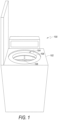
- FIG. 1 illustrates a fluid separation system according to the related art.
- a fluid separation system 100 includes a floor standing-type centrifuge 102; a rotor assembly 104 configured to be rotated by a motor about an axis of rotation 106; and at least one modular fluid separation cassette 108 affixed to the rotor assembly 104.
- the components of fluid separation system 100 together define a sterile and disposable fluid separation system.
- the centrifuge 102 is a floor standing-type centrifuge.
- the centrifuge 102 is capable of housing one or more modular fluid separation cassettes 108 of varying volumes and may be suitable for fluid separation of a higher volume than a benchtop-type or other small-scale centrifuge.
- the floor-standing centrifuge 102 may be capable of housing one or more modular fluid separation cassettes 108 which may each be configured to separate from 1ml to 300ml of whole blood. More particularly, embodiments may be capable of separating between 10ml and 125ml of whole blood.
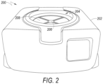
- FIG. 2 illustrates another fluid separation system according to the related art.
- the fluid separation system 200 includes a benchtop-type centrifuge 202; a rotor assembly 204 configured to be rotated by a motor about an axis of rotation 206; and at least one modular fluid separation cassette 208 affixed to the rotor assembly 204.
- the components of fluid separation system 200 together define a sterile and disposable fluid separation system.
- the bench top-type centrifuge 202 may be capable of housing cassettes 208 of varying volumes and may be suitable for the separation of samples having a lower volume than the volume of samples suitable in a floor standing-type centrifuge 102 or other centrifuge.
- the benchtop-type centrifuge 202 may be capable of housing one or more cassettes 208 which may each be configured to separate between 1ml and 125ml of whole blood. More particularly, embodiments may capable of separating between 10ml and 60ml of whole blood.
- any of the centrifuge, the components of the rotor assembly or the cassettes may include any of one or more processors, embedded code, integrated hardwiring or circuitry, embedded sensors, or any other electronic means which may allow for one-way or for bi-directional wired or wireless communication, and which may allow for monitoring, assessment and control of system components.
- the present application proposes novel cassette components and novel Normally Open Valves (NOVs) and Normally Closed Valves (NCVs) to substitute for, or to compliment, what is known in the art.
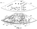
- FIG. 3 is an exploded view of a partial centrifuge cassette assembly according to the related art.
- partial centrifuge cassette assembly 300 comprises cassette top plate 302, including resistor insertion basins 304; and cassette bottom plate 306, including fluidic chambers 308, fluidic channels 310 and valve insertion voids 312.
- Cassette top plate 302 and cassette bottom plate 306 are prefabricated.
- Each of top and bottom plate 302,306 is made of a thermoplastic material.
- plates 302,306 comprise polypropylene and are produced in an injection molding process.
- the prefabricated plates 302, 306 are preferably fitted together using a hot plate welding process.
- NOVs and NCVs according to embodiments of this application are inserted into valve insertion voids 312.
- Resistor insertion basins 304 in top plate 302 are configured to receive resistors (not shown) used to actuate the valves, and accordingly correspond to the location of the valve insertion voids 312 in cassette bottom plate 306.
- resistor arrays including resistors placed in resistor insertion basins 304 and, optionally, a liquid impermeable layer or treatment applied to the cassette bottom plate in order to prohibit an ingress and egress of unwanted fluid into the cassette.
- additional layers or treatments are incorporated into the cassette assembly after the hot plate welding process is complete.
- the centrifuge cassette assembly is loaded with a fluid, such as blood or a blood product, and spun in a centrifuge.
- a fluid such as blood or a blood product
- centrifugal force causes the fluid in the cassette to flow outward (i.e., downhill) in the G-field and separate.
- the position of fluidic chambers and fluidic channels throughout the cassette determine the flow of fluid under centrifugal force.
- the processing of the cassette including the speed and timing of the centrifuge, is determined based on the relative size of the cassette and the relative sizes, positions and geometries of its various fluidic chambers and channels. Processing likewise depends upon the components and characteristics of the fluid to be separated.
- the cassette may be designed to separate the whole blood into plasma, Red Blood Cells (RBCs), White Blood Cells (WBCs) and platelets.
- RBCs Red Blood Cells
- WBCs White Blood Cells
- NOVs Normally Open Valves
- NCVs Normally Closed Valves
- NOVs and NCVs described herein are designed to be inserted into the cassette assembly after the cassette halves have been joined in the hot plate welding process.
- a single NOV or NCV may be positioned in a fluid channel, whereas a combination of NCVs and NOVs may be positioned in a fluidic channel in other embodiments.
- the latter configuration allows the fluidic channel to be both opened and closed. For instance, fluid may be initially held in position by an NCV which is then actuated causing fluid to flow through the channel. The channel may subsequently be closed by actuation of an NOV.
- the individual top and bottom cassette halves 302,306 are produced in an injection molding process; however, the method of manufacturing of the plates is not limited.
- Various alternative manufacturing methods not being part of the claimed invention include, but are not limited to, compression molding, thermoforming, three-dimensional printing or any other suitable manufacturing method.
- the base materials chosen for the manufacture of the top and bottom cassette plates is similarly not limited and may include any of several thermoplastic polymers such as polypropylene, polystyrene, and the like.
- the cassette components may also be hydrophobic or may include a hydrophobic coating or a hydrophobic treatment.
- the cassette halves may be of a dissimilar material. For example, a polypropylene top cassette half may be joined with a mixed or non-polypropylene bottom cassette half.
- top and bottom cassette plates are preferably joined in a hot plate welding process.
- Hot plate welding is highly precise, highly efficient and relatively inexpensive. Modern hot plate welding processes achieve rapid cycle time and consistent weld quality using reduced tooling.
- a further advantage of hot plate welding is the ability to join a variety of thermoplastic materials. Nonetheless, in further embodiments, alternative techniques may be used to join cassette plates, such as laser welding and ultrasonic welding.
- cassettes described herein may be single use (i.e., disposable) or multiple use, and may be of a variety of types, sizes and configurations.
- the cassettes described herein may take the form of a "wedge," or of a segment of a disk shape. In such embodiments, several cassettes together may form a complete disk shape. In other embodiments, a single cassette may take the form of an entire disk.
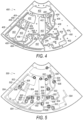
- FIG. 4 is a plan view of a bottom plate of a centrifuge cassette assembly according to an embodiment of the present application.
- the centrifuge cassette bottom plate 400 includes fluidic chambers 402; fluidic channels 404; valve insertion voids 406; and weld beads 408.
- Fluidic chambers 402 are connected by fluidic channels 404. Fluidic channels 404 determine the path of fluid flow between fluidic chambers 402. Fluidic channels 404 incorporate valve insertion voids 406 including lower valve seats (shown below) into which insertion valves are respectively inserted and seated in the fluidic channel 404.
- Weld beads 408 are a deposit or an embankment of base material used to weld the bottom plate 400 and top plate (as shown in FIG. 5 ) together. As shown, the weld beads 408 essentially follow the contour of the fluidic chambers 402 and fluidic channels 404. During hot plate welding of cassette assembly, complementary weld beads on the top plate (as shown in FIG. 5 ) are heated and joined with molten base material from the weld beads 408 of the bottom plate.
- FIG. 5 is a plan view of a top plate of a centrifuge cassette assembly according to an embodiment of the present application.
- the centrifuge cassette top plate 500 includes upper valve seats 502; weld beads 504; and resistor insertion basins 506.
- Upper valve seats 502 are configured to slidably accept an end portion (i.e., an insertion portion) of an insertion valve once the cassette halves have been joined. That is, once the cassette halves are joined, insertion valves are inserted into valve insertion voids 406 of the lower cassette plate 400 shown in FIG. 4 and seated in each of lower valve seats (shown below) and upper valve seats 502. Proper seating of the valve is important for maintaining valve integrity under the high fluidic pressures in the fluid channel.
- weld beads 504 of the top plate 500 essentially follow the contour of the fluidic channels 402 and chambers 404 of the bottom plate. That is, weld beads 504 of top plate 500 and weld beads 408 of bottom plate 400 are precisely positioned to align with one another to facilitate joining of the plates.
- excess molten base material from the cassette welding process may flow into a flash well or material displacement well (not shown) positioned adjacent to either or both of weld beads 408, 504.
- the material displacement well exists between the weld beads and the adjacent fluidic channel or fluidic chamber. In this configuration, any excess weld material resulting from the joining of the cassette plates flows into the material displacement well and remains isolated from the fluid channels and chambers.
- the position and form of the weld beads 408, 504 may vary. That is, although the weld beads 408, 504 will generally be deposited so as to contour the fluidic channels and chambers, the weld beads 408, 504 may take any form or be deposited in any manner desirable for the joining of the cassette plates. The position of displacement wells may vary accordingly.
- the NCV is comprised of a valve base 602 and seal posts 604 supporting valve rib 608.
- Interference seal member 606 forms part of the valve base 602, as shown, and is configured to engage an interference seal member of the lower valve seat (shown below) positioned in the valve insertion void of the fluidic channel of the cassette bottom half. This engagement between interference seal members of the valve and the lower valve seat creates an interference seal capable of securing the bottom of the valve in the lower valve seat of the valve insertion void.
- seal posts 604 extend upward from valve base 602 and taper toward the top of the NCV 600. These tapers form another aspect of valve geometry important in facilitating valve insertion and proper valve seating, and which further contribute to the securing of the valve in the fluidic channel.
- the top portions (i.e., insertion portions) of the seal posts 604 and valve rib 608 are configured to slidably engage the upper valve seat (shown below) in the top cassette plate. When properly seated, insertion portions or end portions of seal posts 604 are securely nested in the valve seat of the top plate, and valve rib 608 is oriented perpendicular to, and fully obstructs, the fluidic channel.
- NCV 600 To actuate and open NCV 600, electrical energy is inputted into a resistor positioned in the top plate above the valve rib 608. Heat from the resistor causes the valve rib 608 to soften and fold, opening the channel and allowing fluid to flow.
- NCV 600 may assume any configuration that includes an actuatable rib sufficiently supported to withstand the high fluidic pressures associated with centrifugation (i.e., fluidic pressures of up to 120 PSI).
- portions of the NCV 600 may be removed or otherwise configured to facilitate potting of the NCV 600 in the cassette assembly.
- an adhesive may be used as potting material.
- interference seal members 606 form an essentially semi-circular convex protrusion.
- This protruding interference seal member 606 is configured to cooperate with a complimentary interference seal member of a valve seat.
- the complimentary interference seal member includes an essentially semi-circular concave aspect configured to accommodate interference seal member 606.
- interference seal member configurations may vary, and may include a variety of geometries in either single or multiple seal configurations. Any chosen interference seal member configuration must be capable of securing the valve in the valve seat throughout operation and preventing an ingress or egress of fluid with respect to the fluid channel.
- FIG. 6B is a top view of a NCV 600.
- NCV 600 comprises seal posts 604 and a valve rib 608.
- top portions (i.e., seating portions) of seal posts 604 and rib 608 are seated into the upper valve seat of the top plate and valve rib 608 is oriented perpendicular to the fluidic channel.
- the seating portions of the seal posts 610 and valve rib 608 are seated deeply enough in the top plate to impart the structural integrity required for the valve to withstand the high fluidic pressures in the channel.
- FIGS. 7A and 7B are alternative views of a Normally Open Valve (NOV) according to an embodiment of the present application.
- NOV Normally Open Valve
- FIG. 7A is a side view of a NOV 700.
- NOV 700 includes valve body 702, interference seal members 704; and a lumen 706.
- valve 700 is essentially configured as an asymmetrical combination of two truncated cones.
- the portion of the valve body 702 having the largest diameter is the point of intersection of interference seal members 704.
- the bottom truncated conical portion of the valve 700 tapers gently inward toward the bottom of the valve 700.
- the top truncated conical portion of the NOV 700 tapers more aggressively inward toward the top of the NOV 700.
- This truncated, bi-conical valve configuration forms interference seal members 704 which cooperate with complimentary interference seal members in a lower valve seat of a valve insertion void to seat the NOV 700 in a fluidic channel of a centrifugal cassette.
- the top portion (i.e., an insertion portion) of the NOV 700 cooperates with an upper valve seat in the cassette top plate, and interference seal members 704 cooperate with complimentary interference seal members of the lower valve seat in the valve insertion void of the bottom plate.
- Lumen 706 is aligned with the fluidic channel, forming a continuous and unobstructed flow path in the fluidic channel. Proper seating of the NOV 700 causes the valve to securely "snap" into place.
- NOV 700 design may vary.
- a NOV 700 may be configured to include irregular aspects more aggressive interference seal members, or to include a higher number of interference seal members.
- one or more of the tapered aspects of the NOV 700 may include a concave aspect.
- Interference seal members may optionally be further included in the top portion or seating portion of the NOV 700 and may cooperate with interference seal members of an upper valve seat.
- Lumen geometry 706 may also vary. For instance, a lumen having a different cross-sectional area or geometry, or a lumen including a different flow path may be incorporated into NOV 700.
- a valve configured to include a torturous fluidic flow path or a fluid flow path including a small cross section may be implemented to decrease flow rate.
- Alternative valve designs may similarly be implemented, for example, to improve aspects of valve actuation or reliability.
- FIG. 7B is a top view of a NOV 700.
- NOV 700 includes valve body 702 and lumen 706.
- the lumen 706 When correctly inserted and seated in the cassette, the lumen 706 is aligned with the fluidic channel of the cassette, allowing the fluidic channel to remain unobstructed until actuation of the valve.
- NCVs 600 and NOVs 700 are injection molded; however, in embodiments, NCVs 600 and NOVs 700 may be molded using alternative conventional methods.
- NCVs 600 and NOVs 700 are semi-rigid and made of an elastomeric material. The semi-rigidity of the valves, including the interference seal members, provides the valves with both sufficient flexibility to be inserted into the cassette and properly seat, and sufficient rigidity to maintain valve integrity under high fluidic pressure.
- valve materials examples include Ethylene Vinyl Acetate (EVA) wax and EVA blends.
- EVA Ethylene Vinyl Acetate
- DuPont TM Elvax ® 410 ethyl-vinyl acetate copolymer resin
- Such materials may exhibit a narrow or “sharp" melting point and favorable flexibility and surface adhesion.
- Other materials having characteristics similar to EVA may also be used.
- FIGS. 8A to 8C are alternative views of a cassette assembly including a Normally Closed Valve (NCV) seated in a fluidic channel of the cassette assembly according to an embodiment of the present application.
- NCV Normally Closed Valve
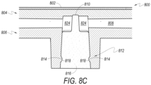
- the cassette assembly 800 includes a resistor layer 802; a top cassette plate 804; a bottom cassette plate 806; a fluidic channel 808, including an upper valve seat 810 and a lower valve seat 812, the lower valve seat 812 incorporating interference seal members 814; an NCV 816, including interference seal members 818; seal posts 820 and rib 822; and rib displacement zone 824.
- FIG. 8A is a top view of the NCV 816 seated in a fluidic channel 808 of a centrifuge cassette assembly 800 of FIG. 8B .
- fluidic channel 808 includes concave recessions forming upper valve seat 810.
- Upper valve seat 810 is configured to receive and accommodate end portions of valve sealing posts 820 and rib 822 of NCV 816.
- the concave recessions of upper valve seat 810 surrounding end portions of the NCV 816 assist in securing the valve against the high fluidic pressures in the channel 808.
- the specific dimensions of the upper valve seat 810 generally conform to the geometry of the valve; however, in embodiments, the geometry of the valve seat 810 is not limited and any dimensions sufficient to secure the valve in place against the fluidic pressure in the channel 808 may suffice.
- FIG. 8B is a cross-section view of cassette assembly 800 including NCV 816 seated in fluidic channel 808. As shown in FIG. 8B , top plate 804 and bottom plate 806 are in a joined state and NCV 816 has been inserted into the joined cassette halves. Interference seal members 818 of NCV 816 are cooperating with interference seal members 814 of lower valve seat 812 to secure NCV 816 in place. Upper valve seat 806 has received a seating portion or a top portion of sealing posts 820 and rib 822.
- lower valve seat 812 is configured to compliment the geometry of NCV 816.
- interference seal members 814 of lower valve seat 812 act in cooperation with complimentary interference seal members 818 of the NCV 816 to securely seat the NCV 816 in the fluid channel. That is, the valves are mechanically pressed into the insertion void to engage interference seal members, causing the valve to "click" in place.
- FIG. 8C is another cross-section view of cassette assembly 800 including NCV 816 seated in fluidic channel 808.
- a rib displacement zone 824 exists within the fluidic channel 808 on either side of the rib 822 of seated NCV 816.
- Rib displacement zone 824 provides a space for the deformed rib to rest once the NCV has been actuated. That is, actuation (i.e., heating) of NCV 816 allows for the fluidic pressures in the fluidic channel 808 to deform the malleable rib 822, forcing it downward by the flow of fluid. As the rib 822 is forced into the rib displacement zone 824, obstruction of the fluid channel 808 by the rib is avoided.
- the specific design and exact dimension of the rib displacement zone 824 is not limited; any rib displacement zone 824 providing a space for actuated rib 822 to rest without obstructing fluid channel 808 may be incorporated.
- a single rib displacement zone 824 may exist in the fluid channel 808 only on the downhill side of, or downstream of, valve rib 822.
- resistor layer 802 is included in the cassette assembly.
- the resistor layer 802 is adhered to the top of the top plate 804 and includes a resistor positioned above the upper valve seat 810 such that, upon the inputting of sufficient electrical energy, the valve 816 will actuate.
- a liquid impermeable layer may be adhered to the bottom of the bottom plate 806 to prevent liquid ingress and egress into fluid channel 808 by way of cooperating interference seal members 814, 818.
- FIGS. 9A and 9B are alternative views of a NOV seated in a fluidic channel of a centrifuge cassette assembly according to an embodiment of the present application.
- the cassette assembly 900 includes a resistor layer 902; top cassette plate 904; bottom cassette plate 906; a fluidic channel 908, including an upper valve seat 910 and a lower valve seat 912, the lower valve seat incorporating interference seal members 914; and a NOV 916, including interference seal members 918 and a lumen 920.
- FIG. 9A is a top view of the NOV 916 seated in a fluidic channel of a centrifuge cassette assembly 900 of FIG. 9B .
- fluidic channel 908 includes concave recessions forming upper valve seat 910.
- Upper valve seat 910 is configured to receive and accommodate an end portion of NOV 916.
- the concave recessions of upper valve seat 910 surround an end portion of the NOV 910 and assist in securing the NOV 910 against the high fluidic pressures in the channel 908.
- the specific dimensions of the upper valve seat 910 generally conform to the geometry of the NOV; however, in embodiments, the geometry of the upper valve seat 910 is not limited and any dimensions sufficient to secure the valve in place against the fluidic pressure in the channel 908 may suffice.
- FIG. 9B is a cross-section view of cassette assembly 900 including NOV 916 seated in fluidic channel 908. As shown in FIG. 9B , top plate 904 and bottom plate 906 are in a joined state and NOV 916 has been inserted into the joined cassette halves. Interference seal members 914 of NOV 916 are cooperating with interference seal members 918 of lower valve seat 912 to secure NOV 916 in place. Upper valve seat 910 has received a seating portion or a top portion of NOV 916.
- lower valve seat 912 is configured to compliment the geometry of NOV 916.
- interference seal members 914 of lower valve seat 912 act in cooperation with complimentary interference seal members 918 of the NOV 916 to securely seat the NOV 916 in the fluid channel 908. That is, the valves are mechanically pressed into the insertion void to engage interference seal members, causing the valve to "click" in place.
- the resistor layer 902 is adhered to the top of the top plate 904 and includes a resistor positioned above the upper valve seat 910 such that, upon the inputting of sufficient electrical energy, the valve 916 will actuate. Placement of the resistor, and the resistor insertion basins, requires a position that is sufficiently proximate to the valve for adequate heating and resultant valve actuation, yet sufficiently distant from the valve to allow the valve seating portions to seat deeply in the cassette top plate.
- a liquid impermeable layer may be adhered to the bottom of the bottom plate 906 to prevent liquid ingress and egress into fluid channel 908 by way of cooperating interference seal members 914, 918.
- the NOVs and NCVs described in the various embodiments herein are inserted into the cassette assembly post hot-plate weld at the time of cassette manufacture. However, in embodiments, NOVs and NCVs may be inserted at a later point before the cassette is placed in service.
- FIG. 10 illustrates a flow diagram of a method of manufacturing a partial cassette assembly according to an embodiment of the present application.
- step 1002 the process begins in step 1002 as each prefabricated thermoplastic cassette half (as shown in FIG. 3 ) is nested in a holding fixture.
- step 1004 joining surfaces of each cassette half are subjected to a heat plate of a heated platen for a predetermined period.
- step 1006 once the joining surfaces of each cassette half reach molten temperature, the plate and platen are removed.
- step 1008 the holding fixtures are pressed together, forcing the molten joining surfaces of the two halves to contact one another, forming a permanent bond.
- step 1010 once the bond formed between the two halves has cooled, the joined cassette halves are removed from the fixtures.
- step 1012 insertion valves are inserted into valve insertion voids and seated in valve seats.
- a resistor layer or resistor array including resistors for actuating the valves is adhered to the top of the joined cassette halves.
- a liquid impermeable layer is also applied to the bottom of the joined cassette halves. Further cassette components may optionally be added to complete the cassette assembly.
- operation of the cassette assembly or its individual components may be controlled by one or more processors included therein and may advantageously comprise a plurality of embedded computer processors that are part of a computer system.
- the computer system may also include components that allow a user to interface with the computer system, including for example, memory and storage devices (RAM, ROM (e.g., CD-ROM, DVD), magnetic drives, optical drives, flash memory,); communication/networking devices (e.g., wired such as modems/network cards, or wireless such as Wi-Fi); input devices such keyboard(s), touch screen(s), camera(s), and/or microphone(s); and output device(s) such as display(s), and audio system(s).
- RAM random access memory
- ROM read-only memory
- magnetic drives e.g., magnetic drives, optical drives, flash memory
- communication/networking devices e.g., wired such as modems/network cards, or wireless such as Wi-Fi
- input devices such keyboard(s), touch screen(s), camera(s),
- fluidic channels may include a variety of valves or valve combinations, including both insertion and non-insertion valves.
- the number of valves may be adjusted for a particular application.
- present application is not limited to the separation of blood. That is, the principles of the present application which are defined by the appended claims may be applicable to the separation or removal of one or more specific constituent from many composite fluids. Accordingly, various modifications and changes may be made in the arrangement, operation, and details of the methods and systems defined in the appended claims of the present application which will be apparent to those skilled in the art.
Landscapes
- Health & Medical Sciences (AREA)
- Engineering & Computer Science (AREA)
- Heart & Thoracic Surgery (AREA)
- Vascular Medicine (AREA)
- Chemical & Material Sciences (AREA)
- Life Sciences & Earth Sciences (AREA)
- General Engineering & Computer Science (AREA)
- Hematology (AREA)
- Biomedical Technology (AREA)
- General Health & Medical Sciences (AREA)
- Animal Behavior & Ethology (AREA)
- Public Health (AREA)
- Veterinary Medicine (AREA)
- Anesthesiology (AREA)
- Dispersion Chemistry (AREA)
- Mechanical Engineering (AREA)
- Cardiology (AREA)
- Analytical Chemistry (AREA)
- Clinical Laboratory Science (AREA)
- Chemical Kinetics & Catalysis (AREA)
- Pathology (AREA)
- Physics & Mathematics (AREA)
- Manufacturing & Machinery (AREA)
- Biophysics (AREA)
- Molecular Biology (AREA)
- Urology & Nephrology (AREA)
- Food Science & Technology (AREA)
- Medicinal Chemistry (AREA)
- Biochemistry (AREA)
- General Physics & Mathematics (AREA)
- Immunology (AREA)
- Ecology (AREA)
- Toxicology (AREA)
- Centrifugal Separators (AREA)
Description
- The present application describes a centrifugal cassette including molded Normally Open Valves (NOVs) and Normally Closed Valves (NCVs). The centrifugal cassette is configured to allow for insertion of the valves after the cassette has been partially manufactured in a hot plate welding process.
- In the medical field, a centrifuge cassette or cartridge may be used to separate human or animal blood. Within the centrifuge cassette exist several fluid chambers connected by a variety of fluid channels operating together under centrifugal force to control the separation process. The flow of fluid in the fluid channels may be regulated by the actuation of NOVs and NCVs which typically include wax elements that are formed into the fluid channels of the centrifuge cassette during its manufacture. Such a cassette is disclosed in
U.S. Patent Application No. 15/719,224, entitled "Centrifugal Fluid Separation Device," filed September 28, 2017 by Terumo BCT, Inc - Problematically, the incorporation of wax elements into the valves during manufacture of the cassette limits the number of methods by which the cassette may be manufactured. For example, although hot plate welding is a preferred manufacturing method for is cost and efficiency advantages, hot plate welding is generally not feasible because wax elements in the valves deform or are otherwise compromised under the heat and pressure of the welding process. For these and other reasons, there exists a need to improve valve and cassette construction. More particularly, a need exists to create valves capable of use in cassettes having sterile fluidic channels and which operate within a high G-field, yet which are also compatible with hot plate welding.
- Embodiments of the present application have been made in view of these and other considerations. However, the relatively specific problems discussed above do not limit the applicability of the embodiments of the present application.
-
US 6 102 897 discloses a microvalve for disposable use with a casing with at least one valve seat and a closing element fusible under thermal application for the opening and/or closing of the microvalve. -
US 2018/0093270 discloses a modular cassette and a method for separating a composite fluid into at least two components parts thereof during centrifugation. - According to the present invention there is provided a method of manufacturing a centrifuge cassette assembly and a centrifuge cassette assembly. A Normally Closed Valve (NCV) and a Normally Open Valve (NOV) for insertion into said cassette assembly are defined in the appended claims.
- According to one aspect of the present application, a Normally Closed Valve (NCV) for insertion into a fluidic channel is provided. The NCV includes at least one interference seal member, at least one valve seal post, and a valve rib. The at least one interference seal member is configured to cooperate with at least one interference seal member of a valve seat of a fluidic channel.
- According to another aspect of the present application, a Normally Open Valve (NOV) for insertion into a fluidic channel is provided. The NOV includes at least one interference seal member and a lumen. The at least one interference seal member is configured to cooperate with at least one interference seal member of a valve seat of fluidic channel.
- According to yet another aspect of the present application, a centrifuge cassette for separating a fluid is provided. The cassette includes a first chamber, a second chamber, a fluidic channel creating a fluid connection between the first chamber and the second chamber, at least one molded insertion valve configured to control the flow of fluid in the fluidic channel, and a heating element for actuating the at least one molded valve.
- According to a further aspect of the claimed invention, a method of manufacturing a centrifuge cassette assembly is provided. The method includes injection molding a first plate, the first plate including an upper valve seat, injection molding a second plate, the second plate including a fluidic channel and a lower valve seat, nesting each of the first plate and the second plate in a holding fixture, heating elements of the first plate and the second plate, aligning the valve seat of the first plate with the valve seat of the second plate, pressing the first plate and the second plate together, joining the plates, and inserting a valve into the joined plates, the valve engaging each of the upper valve seat of the first plate and the lower valve seat of the second plate.
- Further embodiments of the present application include various devices, systems and methods related to centrifuge cassettes and molded insertion valves.
- Non-limiting and non-exhaustive embodiments are described with reference to the following figures.
-
FIG. 1 illustrates a fluid separation system according to the related art; -
FIG. 2 illustrates another fluid separation system according to the related art; -
FIG. 3 is an exploded view of a centrifuge cassette assembly according to an embodiment of the present application; -
FIG. 4 is a plan view of a bottom plate of a centrifuge cassette assembly according to an embodiment of the present application; -
FIG. 5 is a plan view of a top plate of a centrifuge cassette assembly according to an embodiment of the present application; -
FIGS. 6A and 6B are alternative views of a Normally Closed Valve (NCV) according to an embodiment of the present application; -
FIGS. 7A and 7B are alternative views of a Normally Open Valve (NOV) according to an embodiment of the present application; -
FIGS. 8A to 8C are alternative views of a NCV seated in a fluidic channel of a centrifuge cassette assembly according to an embodiment of the present application; -
FIGS. 9A and 9B are alternative views of a NOV seated in a fluidic channel of a centrifuge cassette assembly according to an embodiment of the present application; and -
FIG. 10 is a flow diagram illustrating a method of manufacturing a valve assembly according to an embodiment of the present application. - The principles described in the present application may be further understood by reference to the following detailed description and the embodiments depicted in the accompanying drawings. Although specific features are shown and described below with respect to detailed embodiments, the present application is not limited to the embodiments described below. More particularly, embodiments may be described with respect to opening and closing sterile, microfluidic channels containing composite fluids under centrifugal force; however, such descriptions are merely illustrative, and those of skill in the art will appreciate that the embodiments are not limited to the descriptions herein. Embodiments described herein may be capable of use in products, processes, devices, and systems used to open and close fluid channels in any suitable application. Accordingly, the present application is not limited to the opening and closing of fluid channels in a centrifugal field.
- Throughout this disclosure, the term "cassette half' may be interchanged with the term "cassette plate," and the term "cassette" may be used interchangeably with the term "cartridge."
- Many of the various components of centrifuge systems are known in the art and are described in
U.S. Patent Application No. 15/719,224, entitled "Centrifugal Fluid Separation Device," filed September 28, 2017 by Terumo BCT, Inc -
FIG. 1 illustrates a fluid separation system according to the related art. - Referring to
FIG. 1 , afluid separation system 100 includes a floor standing-type centrifuge 102; arotor assembly 104 configured to be rotated by a motor about an axis ofrotation 106; and at least one modularfluid separation cassette 108 affixed to therotor assembly 104. The components offluid separation system 100 together define a sterile and disposable fluid separation system. - As shown in
FIG. 1 , thecentrifuge 102 is a floor standing-type centrifuge. Thecentrifuge 102 is capable of housing one or more modularfluid separation cassettes 108 of varying volumes and may be suitable for fluid separation of a higher volume than a benchtop-type or other small-scale centrifuge. For example, the floor-standingcentrifuge 102 may be capable of housing one or more modularfluid separation cassettes 108 which may each be configured to separate from 1ml to 300ml of whole blood. More particularly, embodiments may be capable of separating between 10ml and 125ml of whole blood. -
FIG. 2 illustrates another fluid separation system according to the related art. - Referring to
FIG. 2 , thefluid separation system 200 includes a benchtop-type centrifuge 202; arotor assembly 204 configured to be rotated by a motor about an axis ofrotation 206; and at least one modularfluid separation cassette 208 affixed to therotor assembly 204. The components offluid separation system 200 together define a sterile and disposable fluid separation system. - Examples of suitable bench top-type centrifuges, such as that depicted in
FIG. 2 , are common and can be found throughout the art. In embodiments, the bench top-type centrifuge 202 may be capable ofhousing cassettes 208 of varying volumes and may be suitable for the separation of samples having a lower volume than the volume of samples suitable in a floor standing-type centrifuge 102 or other centrifuge. For example, the benchtop-type centrifuge 202 may be capable of housing one ormore cassettes 208 which may each be configured to separate between 1ml and 125ml of whole blood. More particularly, embodiments may capable of separating between 10ml and 60ml of whole blood. - The fluid separation systems of
FIGS. 1 and2 are generally known in the art. In either system, various system components may include electronic control means and electronic communication means. For example, any of the centrifuge, the components of the rotor assembly or the cassettes may include any of one or more processors, embedded code, integrated hardwiring or circuitry, embedded sensors, or any other electronic means which may allow for one-way or for bi-directional wired or wireless communication, and which may allow for monitoring, assessment and control of system components. The present application proposes novel cassette components and novel Normally Open Valves (NOVs) and Normally Closed Valves (NCVs) to substitute for, or to compliment, what is known in the art. -
FIG. 3 is an exploded view of a partial centrifuge cassette assembly according to the related art. - Referring to
FIG. 3 , partialcentrifuge cassette assembly 300 comprises cassettetop plate 302, includingresistor insertion basins 304; andcassette bottom plate 306, includingfluidic chambers 308,fluidic channels 310 and valve insertion voids 312. -
Cassette top plate 302 andcassette bottom plate 306 are prefabricated. Each of top and bottom plate 302,306 is made of a thermoplastic material. In preferred embodiments, plates 302,306 comprise polypropylene and are produced in an injection molding process. Theprefabricated plates plates Resistor insertion basins 304 intop plate 302 are configured to receive resistors (not shown) used to actuate the valves, and accordingly correspond to the location of the valve insertion voids 312 incassette bottom plate 306. Among additional assembly components not shown inFIG. 3 are a resistor array including resistors placed inresistor insertion basins 304 and, optionally, a liquid impermeable layer or treatment applied to the cassette bottom plate in order to prohibit an ingress and egress of unwanted fluid into the cassette. Such additional layers or treatments are incorporated into the cassette assembly after the hot plate welding process is complete. - In operation, the centrifuge cassette assembly is loaded with a fluid, such as blood or a blood product, and spun in a centrifuge. As the cassette spins, centrifugal force causes the fluid in the cassette to flow outward (i.e., downhill) in the G-field and separate. The position of fluidic chambers and fluidic channels throughout the cassette determine the flow of fluid under centrifugal force. Accordingly, the processing of the cassette, including the speed and timing of the centrifuge, is determined based on the relative size of the cassette and the relative sizes, positions and geometries of its various fluidic chambers and channels. Processing likewise depends upon the components and characteristics of the fluid to be separated. In the case of human or animal whole blood, the cassette may be designed to separate the whole blood into plasma, Red Blood Cells (RBCs), White Blood Cells (WBCs) and platelets.
- As fluid flows through the cassette under centrifugal force, the fluidic channels must remain sterile, yet must also include means by which the fluid can be reliably controlled. Fluid control is accomplished using embodiments of the Normally Open Valves (NOVs) and Normally Closed Valves (NCVs) described throughout this application. NOVs and NCVs described herein are designed to be inserted into the cassette assembly after the cassette halves have been joined in the hot plate welding process. In certain embodiments, a single NOV or NCV may be positioned in a fluid channel, whereas a combination of NCVs and NOVs may be positioned in a fluidic channel in other embodiments. The latter configuration allows the fluidic channel to be both opened and closed. For instance, fluid may be initially held in position by an NCV which is then actuated causing fluid to flow through the channel. The channel may subsequently be closed by actuation of an NOV.
- According to the invention, the individual top and bottom cassette halves 302,306 are produced in an injection molding process; however, the method of manufacturing of the plates is not limited. Various alternative manufacturing methods not being part of the claimed invention include, but are not limited to, compression molding, thermoforming, three-dimensional printing or any other suitable manufacturing method.
- The base materials chosen for the manufacture of the top and bottom cassette plates is similarly not limited and may include any of several thermoplastic polymers such as polypropylene, polystyrene, and the like. The cassette components may also be hydrophobic or may include a hydrophobic coating or a hydrophobic treatment. In various further embodiments, the cassette halves may be of a dissimilar material. For example, a polypropylene top cassette half may be joined with a mixed or non-polypropylene bottom cassette half.
- As mentioned above, the top and bottom cassette plates are preferably joined in a hot plate welding process. Hot plate welding is highly precise, highly efficient and relatively inexpensive. Modern hot plate welding processes achieve rapid cycle time and consistent weld quality using reduced tooling. A further advantage of hot plate welding is the ability to join a variety of thermoplastic materials. Nonetheless, in further embodiments, alternative techniques may be used to join cassette plates, such as laser welding and ultrasonic welding.
- In embodiments, cassettes described herein may be single use (i.e., disposable) or multiple use, and may be of a variety of types, sizes and configurations. For example, the cassettes described herein may take the form of a "wedge," or of a segment of a disk shape. In such embodiments, several cassettes together may form a complete disk shape. In other embodiments, a single cassette may take the form of an entire disk.
-
FIG. 4 is a plan view of a bottom plate of a centrifuge cassette assembly according to an embodiment of the present application. - Referring to
FIG. 4 , the centrifugecassette bottom plate 400 includesfluidic chambers 402;fluidic channels 404; valve insertion voids 406; andweld beads 408. -
Fluidic chambers 402 are connected byfluidic channels 404.Fluidic channels 404 determine the path of fluid flow betweenfluidic chambers 402.Fluidic channels 404 incorporate valve insertion voids 406 including lower valve seats (shown below) into which insertion valves are respectively inserted and seated in thefluidic channel 404. -
Weld beads 408 are a deposit or an embankment of base material used to weld thebottom plate 400 and top plate (as shown inFIG. 5 ) together. As shown, theweld beads 408 essentially follow the contour of thefluidic chambers 402 andfluidic channels 404. During hot plate welding of cassette assembly, complementary weld beads on the top plate (as shown inFIG. 5 ) are heated and joined with molten base material from theweld beads 408 of the bottom plate. -
FIG. 5 is a plan view of a top plate of a centrifuge cassette assembly according to an embodiment of the present application. - Referring to
FIG. 5 , the centrifugecassette top plate 500 includes upper valve seats 502;weld beads 504; andresistor insertion basins 506. -
Upper valve seats 502 are configured to slidably accept an end portion (i.e., an insertion portion) of an insertion valve once the cassette halves have been joined. That is, once the cassette halves are joined, insertion valves are inserted into valve insertion voids 406 of thelower cassette plate 400 shown inFIG. 4 and seated in each of lower valve seats (shown below) and upper valve seats 502. Proper seating of the valve is important for maintaining valve integrity under the high fluidic pressures in the fluid channel. - As with the
bottom plate 400, theweld beads 504 of thetop plate 500 essentially follow the contour of thefluidic channels 402 andchambers 404 of the bottom plate. That is,weld beads 504 oftop plate 500 andweld beads 408 ofbottom plate 400 are precisely positioned to align with one another to facilitate joining of the plates. - In various alternative embodiments of the
plates FIG. 4 and FIG. 5 , excess molten base material from the cassette welding process may flow into a flash well or material displacement well (not shown) positioned adjacent to either or both ofweld beads - In yet further alternative embodiments, the position and form of the
weld beads weld beads weld beads -
FIGS. 6A and 6B are alternative views of a Normally Closed Valve (NCV) according to an embodiment of the present application. -
FIG. 6A is a perspective view ofNCV 600. Referring toFIG. 6A , theNCV 600 comprises avalve base 602; seal posts 604;interference seal member 606; and avalve rib 608. - As shown in
FIG. 6 , the NCV is comprised of avalve base 602 andseal posts 604 supportingvalve rib 608.Interference seal member 606 forms part of thevalve base 602, as shown, and is configured to engage an interference seal member of the lower valve seat (shown below) positioned in the valve insertion void of the fluidic channel of the cassette bottom half. This engagement between interference seal members of the valve and the lower valve seat creates an interference seal capable of securing the bottom of the valve in the lower valve seat of the valve insertion void. - Notably, seal posts 604 extend upward from
valve base 602 and taper toward the top of theNCV 600. These tapers form another aspect of valve geometry important in facilitating valve insertion and proper valve seating, and which further contribute to the securing of the valve in the fluidic channel. The top portions (i.e., insertion portions) of the seal posts 604 andvalve rib 608 are configured to slidably engage the upper valve seat (shown below) in the top cassette plate. When properly seated, insertion portions or end portions ofseal posts 604 are securely nested in the valve seat of the top plate, andvalve rib 608 is oriented perpendicular to, and fully obstructs, the fluidic channel. - To actuate and open
NCV 600, electrical energy is inputted into a resistor positioned in the top plate above thevalve rib 608. Heat from the resistor causes thevalve rib 608 to soften and fold, opening the channel and allowing fluid to flow. - In alternative embodiments, the design of
NCV 600 is not limited. For instance,NCV 600 may assume any configuration that includes an actuatable rib sufficiently supported to withstand the high fluidic pressures associated with centrifugation (i.e., fluidic pressures of up to 120 PSI). In yet further embodiments, portions of theNCV 600 may be removed or otherwise configured to facilitate potting of theNCV 600 in the cassette assembly. In such embodiments, an adhesive may be used as potting material. - As shown in
FIG. 6A ,interference seal members 606 form an essentially semi-circular convex protrusion. This protrudinginterference seal member 606 is configured to cooperate with a complimentary interference seal member of a valve seat. The complimentary interference seal member includes an essentially semi-circular concave aspect configured to accommodateinterference seal member 606. Upon insertion of the valve into the cassette, the complimentary interference seal members of the respective valve and valve insertion void essentially "snap" into place with one another. In embodiments, interference seal member configurations may vary, and may include a variety of geometries in either single or multiple seal configurations. Any chosen interference seal member configuration must be capable of securing the valve in the valve seat throughout operation and preventing an ingress or egress of fluid with respect to the fluid channel. -
FIG. 6B is a top view of aNCV 600. Referring toFIG. 6B ,NCV 600 comprises seal posts 604 and avalve rib 608. - When
NCV 600 is properly inserted into a cassette, top portions (i.e., seating portions) ofseal posts 604 andrib 608 are seated into the upper valve seat of the top plate andvalve rib 608 is oriented perpendicular to the fluidic channel. Importantly, the seating portions of the seal posts 610 andvalve rib 608 are seated deeply enough in the top plate to impart the structural integrity required for the valve to withstand the high fluidic pressures in the channel. -
FIGS. 7A and 7B are alternative views of a Normally Open Valve (NOV) according to an embodiment of the present application. -
FIG. 7A is a side view of aNOV 700. Referring toFIG. 7A ,NOV 700 includesvalve body 702,interference seal members 704; and alumen 706. - As shown in
FIG. 7A ,valve 700 is essentially configured as an asymmetrical combination of two truncated cones. The portion of thevalve body 702 having the largest diameter is the point of intersection ofinterference seal members 704. The bottom truncated conical portion of thevalve 700 tapers gently inward toward the bottom of thevalve 700. The top truncated conical portion of theNOV 700 tapers more aggressively inward toward the top of theNOV 700. This truncated, bi-conical valve configuration formsinterference seal members 704 which cooperate with complimentary interference seal members in a lower valve seat of a valve insertion void to seat theNOV 700 in a fluidic channel of a centrifugal cassette. - When properly seated in the cassette, the top portion (i.e., an insertion portion) of the
NOV 700 cooperates with an upper valve seat in the cassette top plate, andinterference seal members 704 cooperate with complimentary interference seal members of the lower valve seat in the valve insertion void of the bottom plate.Lumen 706 is aligned with the fluidic channel, forming a continuous and unobstructed flow path in the fluidic channel. Proper seating of theNOV 700 causes the valve to securely "snap" into place. - To actuate and close the NOV, electrical energy is inputted into a resistor positioned in the top cassette plate above the
lumen 704. Heat from the resistor causesNOV 700 material around thelumen 704 to become molten, collapsing and closing the valve. - In embodiments,
NOV 700 design may vary. For instance, aNOV 700 may be configured to include irregular aspects more aggressive interference seal members, or to include a higher number of interference seal members. For instance, one or more of the tapered aspects of theNOV 700 may include a concave aspect. Interference seal members may optionally be further included in the top portion or seating portion of theNOV 700 and may cooperate with interference seal members of an upper valve seat.Lumen geometry 706 may also vary. For instance, a lumen having a different cross-sectional area or geometry, or a lumen including a different flow path may be incorporated intoNOV 700. For instance, a valve configured to include a torturous fluidic flow path or a fluid flow path including a small cross section may be implemented to decrease flow rate. Alternative valve designs may similarly be implemented, for example, to improve aspects of valve actuation or reliability. -
FIG. 7B is a top view of aNOV 700. Referring toFIG. 7B ,NOV 700 includesvalve body 702 andlumen 706. - When correctly inserted and seated in the cassette, the
lumen 706 is aligned with the fluidic channel of the cassette, allowing the fluidic channel to remain unobstructed until actuation of the valve. - Preferably, the
NCVs 600 andNOVs 700 are injection molded; however, in embodiments,NCVs 600 andNOVs 700 may be molded using alternative conventional methods.NCVs 600 andNOVs 700 are semi-rigid and made of an elastomeric material. The semi-rigidity of the valves, including the interference seal members, provides the valves with both sufficient flexibility to be inserted into the cassette and properly seat, and sufficient rigidity to maintain valve integrity under high fluidic pressure. - Examples of suitable valve materials include Ethylene Vinyl Acetate (EVA) wax and EVA blends. In embodiments, DuPont™ Elvax® 410 (ethyl-vinyl acetate copolymer resin) may be preferred. Such materials may exhibit a narrow or "sharp" melting point and favorable flexibility and surface adhesion. Other materials having characteristics similar to EVA may also be used.
-
FIGS. 8A to 8C are alternative views of a cassette assembly including a Normally Closed Valve (NCV) seated in a fluidic channel of the cassette assembly according to an embodiment of the present application. - Referring to
FIGS. 8A to 8C , thecassette assembly 800 includes aresistor layer 802; atop cassette plate 804; abottom cassette plate 806; afluidic channel 808, including anupper valve seat 810 and alower valve seat 812, thelower valve seat 812 incorporatinginterference seal members 814; anNCV 816, includinginterference seal members 818; seal posts 820 andrib 822; andrib displacement zone 824. -
FIG. 8A is a top view of theNCV 816 seated in afluidic channel 808 of acentrifuge cassette assembly 800 ofFIG. 8B . As shown inFIG. 8A ,fluidic channel 808 includes concave recessions formingupper valve seat 810.Upper valve seat 810 is configured to receive and accommodate end portions ofvalve sealing posts 820 andrib 822 ofNCV 816. The concave recessions ofupper valve seat 810 surrounding end portions of theNCV 816 assist in securing the valve against the high fluidic pressures in thechannel 808. The specific dimensions of theupper valve seat 810 generally conform to the geometry of the valve; however, in embodiments, the geometry of thevalve seat 810 is not limited and any dimensions sufficient to secure the valve in place against the fluidic pressure in thechannel 808 may suffice. -
FIG. 8B is a cross-section view ofcassette assembly 800 includingNCV 816 seated influidic channel 808. As shown inFIG. 8B ,top plate 804 andbottom plate 806 are in a joined state andNCV 816 has been inserted into the joined cassette halves.Interference seal members 818 ofNCV 816 are cooperating withinterference seal members 814 oflower valve seat 812 to secureNCV 816 in place.Upper valve seat 806 has received a seating portion or a top portion of sealingposts 820 andrib 822. - As shown,
lower valve seat 812 is configured to compliment the geometry ofNCV 816. In particular,interference seal members 814 oflower valve seat 812 act in cooperation with complimentaryinterference seal members 818 of theNCV 816 to securely seat theNCV 816 in the fluid channel. That is, the valves are mechanically pressed into the insertion void to engage interference seal members, causing the valve to "click" in place. -
FIG. 8C is another cross-section view ofcassette assembly 800 includingNCV 816 seated influidic channel 808. As shown inFIG. 8C , arib displacement zone 824 exists within thefluidic channel 808 on either side of therib 822 ofseated NCV 816.Rib displacement zone 824 provides a space for the deformed rib to rest once the NCV has been actuated. That is, actuation (i.e., heating) ofNCV 816 allows for the fluidic pressures in thefluidic channel 808 to deform themalleable rib 822, forcing it downward by the flow of fluid. As therib 822 is forced into therib displacement zone 824, obstruction of thefluid channel 808 by the rib is avoided. In embodiments, the specific design and exact dimension of therib displacement zone 824 is not limited; anyrib displacement zone 824 providing a space for actuatedrib 822 to rest without obstructingfluid channel 808 may be incorporated. In certain embodiments, a singlerib displacement zone 824 may exist in thefluid channel 808 only on the downhill side of, or downstream of,valve rib 822. - As shown in both
FIGS. 8B and8C ,resistor layer 802 is included in the cassette assembly. Theresistor layer 802 is adhered to the top of thetop plate 804 and includes a resistor positioned above theupper valve seat 810 such that, upon the inputting of sufficient electrical energy, thevalve 816 will actuate. - In further embodiments, a liquid impermeable layer may be adhered to the bottom of the
bottom plate 806 to prevent liquid ingress and egress intofluid channel 808 by way of cooperatinginterference seal members -
FIGS. 9A and 9B are alternative views of a NOV seated in a fluidic channel of a centrifuge cassette assembly according to an embodiment of the present application. - Referring to
FIGS. 9A and 9B , the cassette assembly 900 includes aresistor layer 902;top cassette plate 904;bottom cassette plate 906; afluidic channel 908, including anupper valve seat 910 and alower valve seat 912, the lower valve seat incorporatinginterference seal members 914; and aNOV 916, includinginterference seal members 918 and alumen 920. -
FIG. 9A is a top view of theNOV 916 seated in a fluidic channel of a centrifuge cassette assembly 900 ofFIG. 9B . As shown inFIG. 9A ,fluidic channel 908 includes concave recessions formingupper valve seat 910.Upper valve seat 910 is configured to receive and accommodate an end portion ofNOV 916. The concave recessions ofupper valve seat 910 surround an end portion of theNOV 910 and assist in securing theNOV 910 against the high fluidic pressures in thechannel 908. The specific dimensions of theupper valve seat 910 generally conform to the geometry of the NOV; however, in embodiments, the geometry of theupper valve seat 910 is not limited and any dimensions sufficient to secure the valve in place against the fluidic pressure in thechannel 908 may suffice. -
FIG. 9B is a cross-section view of cassette assembly 900 includingNOV 916 seated influidic channel 908. As shown inFIG. 9B ,top plate 904 andbottom plate 906 are in a joined state andNOV 916 has been inserted into the joined cassette halves.Interference seal members 914 ofNOV 916 are cooperating withinterference seal members 918 oflower valve seat 912 to secureNOV 916 in place.Upper valve seat 910 has received a seating portion or a top portion ofNOV 916. - As shown,
lower valve seat 912 is configured to compliment the geometry ofNOV 916. In particular,interference seal members 914 oflower valve seat 912 act in cooperation with complimentaryinterference seal members 918 of theNOV 916 to securely seat theNOV 916 in thefluid channel 908. That is, the valves are mechanically pressed into the insertion void to engage interference seal members, causing the valve to "click" in place. - The
resistor layer 902 is adhered to the top of thetop plate 904 and includes a resistor positioned above theupper valve seat 910 such that, upon the inputting of sufficient electrical energy, thevalve 916 will actuate. Placement of the resistor, and the resistor insertion basins, requires a position that is sufficiently proximate to the valve for adequate heating and resultant valve actuation, yet sufficiently distant from the valve to allow the valve seating portions to seat deeply in the cassette top plate. - In further embodiments, a liquid impermeable layer may be adhered to the bottom of the
bottom plate 906 to prevent liquid ingress and egress intofluid channel 908 by way of cooperatinginterference seal members
Notably, in most cases, the NOVs and NCVs described in the various embodiments herein are inserted into the cassette assembly post hot-plate weld at the time of cassette manufacture. However, in embodiments, NOVs and NCVs may be inserted at a later point before the cassette is placed in service. -
FIG. 10 illustrates a flow diagram of a method of manufacturing a partial cassette assembly according to an embodiment of the present application. - Referring to
FIG. 10 , the process begins instep 1002 as each prefabricated thermoplastic cassette half (as shown inFIG. 3 ) is nested in a holding fixture. Next, instep 1004, joining surfaces of each cassette half are subjected to a heat plate of a heated platen for a predetermined period. Next, instep 1006, once the joining surfaces of each cassette half reach molten temperature, the plate and platen are removed. Next, instep 1008, the holding fixtures are pressed together, forcing the molten joining surfaces of the two halves to contact one another, forming a permanent bond. Next, instep 1010, once the bond formed between the two halves has cooled, the joined cassette halves are removed from the fixtures. Next, instep 1012, insertion valves are inserted into valve insertion voids and seated in valve seats. - After the hot plate welding of the top and bottom cassette halves, a resistor layer or resistor array including resistors for actuating the valves is adhered to the top of the joined cassette halves. Optionally, as mentioned above, a liquid impermeable layer is also applied to the bottom of the joined cassette halves. Further cassette components may optionally be added to complete the cassette assembly.
- In various embodiments, operation of the cassette assembly or its individual components may be controlled by one or more processors included therein and may advantageously comprise a plurality of embedded computer processors that are part of a computer system. The computer system may also include components that allow a user to interface with the computer system, including for example, memory and storage devices (RAM, ROM (e.g., CD-ROM, DVD), magnetic drives, optical drives, flash memory,); communication/networking devices (e.g., wired such as modems/network cards, or wireless such as Wi-Fi); input devices such keyboard(s), touch screen(s), camera(s), and/or microphone(s); and output device(s) such as display(s), and audio system(s). To assist the operator of the centrifuge cassette assemblies described herein with various aspects of operation, such embodiments may include a graphical user interface with a display that includes an interactive touch screen.
- Notwithstanding the various embodiments specifically enumerated throughout this disclosure, those skilled in the art will appreciate that a variety of modifications and optimizations could be implemented for particular applications. It is to be understood that this application is not limited to any specific configuration described herein. For instance, fluidic channels may include a variety of valves or valve combinations, including both insertion and non-insertion valves. Likewise, the number of valves may be adjusted for a particular application. Additionally, the present application is not limited to the separation of blood. That is, the principles of the present application which are defined by the appended claims may be applicable to the separation or removal of one or more specific constituent from many composite fluids. Accordingly, various modifications and changes may be made in the arrangement, operation, and details of the methods and systems defined in the appended claims of the present application which will be apparent to those skilled in the art.
Claims (15)
- A method of manufacturing a centrifuge cassette assembly (800, 900), the method comprising:injection molding a first plate (804, 904), the first plate including an upper valve seat (810, 910);injection molding a second plate (806, 906), the second plate including a fluidic channel (808, 908) and a lower valve seat (812, 912);nesting each of the first plate (804, 904) and the second plate (806, 906) in a holding fixture;heating elements of the first plate (804, 904) and of the second plate (806, 906);aligning, with one another, the upper valve seat (810, 910) and the lower valve seat (812, 912);pressing the first plate (804, 904) and the second plate together (806, 906), joining of the plates; andinserting a valve into the joined plates, the valve (816, 916) engaging each of the upper valve seat (810, 910) and the lower valve seat (812, 912).
- The method of claim 1, further comprising adhering, to the cassette, a resistor layer (802, 902) and/or further comprising applying, to the cassette, a liquid impermeable layer.
- The method of claim 1 or claim 2, wherein the valve (816, 916) is a Normally Open Valve, NOV (916), or a Normally Closed Valve, NCV (816).
- The method of any one of claims 1-3, wherein the valve (816, 916) is produced in an injection molding process.
- A centrifuge cassette assembly (800, 900) for separating a fluid, the cassette assembly comprising:a first plate (804, 904) including an upper valve seat;a second plate (806, 906) including a fluidic channel (808, 908) and a lower valve seat (812, 912);wherein the first plate (804, 904) and the second plate (806, 906) are nested and joined together so that the upper valve seat (810, 910) is aligned with the lower valve seat (812, 912);a valve (816, 916),characterized in that
said valve is inserted into the joined plates after said first plate (804, 904) and said second plate (806, 906) have been joined together, the valve engaging each of the upper valve seat (810, 910) and the lower valve seat (812, 912). - The method of any one of claims 1-4 or the cassette assembly (800, 900) of claim 5, wherein the valve (816, 916) comprises interference seal members (818, 918) configured to seat the valve in the upper valve seat and the lower valve seat.
- The method of any one of claims 1-4 or 6 or the cassette assembly (800, 900) of claim 5 or claim 6, wherein the valve is a Normally Open Valve, NOV (700, 916), wherein the NOV optionally further comprises a lumen (706, 920) having a same cross-sectional geometry as a portion of the fluidic channel of the second plate.
- The method of any one of claims 1-4 or 6 or the cassette assembly (800, 900) of claim 5 or claim 6, wherein the valve is a Normally Closed Valve, NCV, (600, 816) wherein the NCV optionally further comprises:seal posts (820); anda rib (822).
- The method of any one of claims 1-4 or 6 to 8 or the cassette assembly (800, 900) of any one of claims 5 to 8, wherein the lower valve seat (812, 912) is further configured to accept a bottom portion of the valve,optionally wherein the upper valve seat (810, 910) is further configured to accept a top portion of the valve,optionally wherein the lower valve seat (812, 912) further comprises at least one interference seal member (814, 914) configured to cooperate with an interference seal member (818, 918) of the valve.
- The cassette assembly (800, 900) of any one of claims 5 to 9, further comprising a resistor layer (802, 902) including at least one resistor, and/or further comprising a liquid impermeable layer.
- The cassette assembly (800, 900) of claim 5 or claim 6, wherein the valve is a normally closed valve, NCV, (600, 816) the NCV comprising:a valve base (602) including at least one interference seal member or the interference seal members (606);at least one valve seal post (604); anda valve rib (608);wherein the at least one interference seal member or the interference seal members are configured to cooperate with at least one interference seal member or interference seal members of a valve seat.
- The cassette assembly of claim 11, wherein the valve seal posts (604) are tapered.
- The cassette assembly of claim 5 or claim 6, wherein the valve is a normally open valve, NOV, (700, 916) the NOV comprising:a valve base including at least one interference seal member or the interference seal members; anda lumen (706, 920);wherein the at least one interference seal member is or the interference seal members are configured to cooperate with at least one interference seal member or the interference seal members of a valve seat.
- The cassette assembly of claim 13, wherein the NOV includes at least one truncated conical feature.
- The method of any one of claims 1 to 4 or 6-9 or the cassette assembly of any one of claims 5 to 14, wherein the valve comprises Ethylene Vinyl Acetate, EVA.
Applications Claiming Priority (2)
| Application Number | Priority Date | Filing Date | Title |
|---|---|---|---|
| US201962812666P | 2019-03-01 | 2019-03-01 | |
| PCT/US2020/019914 WO2020180563A1 (en) | 2019-03-01 | 2020-02-26 | Centrifugal cassette with molded insertable valves |
Publications (2)
| Publication Number | Publication Date |
|---|---|
| EP3931476A1 EP3931476A1 (en) | 2022-01-05 |
| EP3931476B1 true EP3931476B1 (en) | 2024-06-19 |
Family
ID=70009400
Family Applications (1)
| Application Number | Title | Priority Date | Filing Date |
|---|---|---|---|
| EP20714766.1A Active EP3931476B1 (en) | 2019-03-01 | 2020-02-26 | Centrifugal cassette with molded insertable valves |
Country Status (4)
| Country | Link |
|---|---|
| US (1) | US12326200B2 (en) |
| EP (1) | EP3931476B1 (en) |
| ES (1) | ES2985539T3 (en) |
| WO (1) | WO2020180563A1 (en) |
Families Citing this family (1)
| Publication number | Priority date | Publication date | Assignee | Title |
|---|---|---|---|---|
| WO2021228336A1 (en) * | 2020-05-11 | 2021-11-18 | Carmo Holding Aps | Rotary valve |
Family Cites Families (6)
| Publication number | Priority date | Publication date | Assignee | Title |
|---|---|---|---|---|
| DE19749011A1 (en) * | 1996-11-19 | 1998-05-20 | Lang Volker | Micro=valve for one time use has opening closed by plug mounted on resistance plate |
| KR101422572B1 (en) * | 2006-09-05 | 2014-07-30 | 삼성전자주식회사 | Centrifugal-force microfluidic device for nucleic acid detection and microfluidic system including the same |
| KR20080073934A (en) * | 2007-02-07 | 2008-08-12 | 삼성전자주식회사 | Valve Filler And Valve Unit With The Same |
| CA2864425C (en) * | 2012-03-16 | 2021-02-16 | Aptargroup, Inc. | Dispensing valve |
| DE102013007190A1 (en) * | 2013-04-25 | 2014-10-30 | Fresenius Medical Care Deutschland Gmbh | Cassette module with integrated centrifugal pump unit |
| WO2018067379A1 (en) * | 2016-10-03 | 2018-04-12 | Terumo Bct, Inc. | Centrifugal fluid separation device |
-
2020
- 2020-02-26 EP EP20714766.1A patent/EP3931476B1/en active Active
- 2020-02-26 WO PCT/US2020/019914 patent/WO2020180563A1/en not_active Ceased
- 2020-02-26 ES ES20714766T patent/ES2985539T3/en active Active
- 2020-02-26 US US17/430,434 patent/US12326200B2/en active Active
Also Published As
| Publication number | Publication date |
|---|---|
| US12326200B2 (en) | 2025-06-10 |
| EP3931476A1 (en) | 2022-01-05 |
| WO2020180563A1 (en) | 2020-09-10 |
| ES2985539T3 (en) | 2024-11-06 |
| US20220112967A1 (en) | 2022-04-14 |
Similar Documents
| Publication | Publication Date | Title |
|---|---|---|
| KR101274113B1 (en) | Magnetic microvalve using metal ball and manufacturing method thereof | |
| AU2009262555B2 (en) | Microfluidic foil structure for metering of fluids | |
| KR100818290B1 (en) | Component Separation Device and Component Separation Method | |
| EP1088640B1 (en) | Method for sealing a filter element in a filter cartridge and filter devices produced therefrom | |
| CN115253383B (en) | Modular Box | |
| EP2134386B1 (en) | Biological fluid filtration systems and methods | |
| KR101578149B1 (en) | Valve unit for microfluid control and manufacturing method thereof | |
| US20060180223A1 (en) | Electrically opended micro fluid-valve | |
| EP2994232B1 (en) | Rotatable microfluidic device with dissolvable release valve and control valve | |
| US10046893B2 (en) | Pattenred film for forming fluid-filled blister, microfluidic blister, and kit and method of forming | |
| EP2604343A1 (en) | Microfluidic device and method of manufacturing the same | |
| WO2001088525A1 (en) | Structurally programmable microfluidic systems | |
| US20080135462A1 (en) | Apparatus and method for separating components | |
| US12326200B2 (en) | Centrifugal cassette with molded insertable valves | |
| WO2012097233A1 (en) | Valves with hydraulic actuation system | |
| KR20150027939A (en) | Microfluidic apparatus | |
| JP2013516582A (en) | Micro valve | |
| EP3996844B1 (en) | Microfluidic chip and valve, production process and uses | |
| US8939165B2 (en) | Microvalve, micropump and manufacturing method | |
| JP2006511762A (en) | Unidirectional microball valve for microfluidic devices | |
| HK1259191A1 (en) | Single use capsule for machines for the dispensing of infused beverages | |
| JP4181046B2 (en) | Sample processing equipment | |
| CN113546699B (en) | Fluid device, apparatus and method for dispensing a fluid | |
| EP3621716B1 (en) | Multiwell plate with variable compression seal |
Legal Events
| Date | Code | Title | Description |
|---|---|---|---|
| STAA | Information on the status of an ep patent application or granted ep patent |
Free format text: STATUS: UNKNOWN |
|
| STAA | Information on the status of an ep patent application or granted ep patent |
Free format text: STATUS: THE INTERNATIONAL PUBLICATION HAS BEEN MADE |
|
| PUAI | Public reference made under article 153(3) epc to a published international application that has entered the european phase |
Free format text: ORIGINAL CODE: 0009012 |
|
| STAA | Information on the status of an ep patent application or granted ep patent |
Free format text: STATUS: REQUEST FOR EXAMINATION WAS MADE |
|
| 17P | Request for examination filed |
Effective date: 20210914 |
|
| AK | Designated contracting states |
Kind code of ref document: A1 Designated state(s): AL AT BE BG CH CY CZ DE DK EE ES FI FR GB GR HR HU IE IS IT LI LT LU LV MC MK MT NL NO PL PT RO RS SE SI SK SM TR |
|
| DAV | Request for validation of the european patent (deleted) | ||
| DAX | Request for extension of the european patent (deleted) | ||
| STAA | Information on the status of an ep patent application or granted ep patent |
Free format text: STATUS: EXAMINATION IS IN PROGRESS |
|
| 17Q | First examination report despatched |
Effective date: 20220929 |
|
| GRAP | Despatch of communication of intention to grant a patent |
Free format text: ORIGINAL CODE: EPIDOSNIGR1 |
|
| STAA | Information on the status of an ep patent application or granted ep patent |
Free format text: STATUS: GRANT OF PATENT IS INTENDED |
|
| INTG | Intention to grant announced |
Effective date: 20230306 |
|
| GRAJ | Information related to disapproval of communication of intention to grant by the applicant or resumption of examination proceedings by the epo deleted |
Free format text: ORIGINAL CODE: EPIDOSDIGR1 |
|
| STAA | Information on the status of an ep patent application or granted ep patent |
Free format text: STATUS: EXAMINATION IS IN PROGRESS |
|
| INTC | Intention to grant announced (deleted) | ||
| GRAP | Despatch of communication of intention to grant a patent |
Free format text: ORIGINAL CODE: EPIDOSNIGR1 |
|
| STAA | Information on the status of an ep patent application or granted ep patent |
Free format text: STATUS: GRANT OF PATENT IS INTENDED |
|
| INTG | Intention to grant announced |
Effective date: 20240126 |
|
| GRAS | Grant fee paid |
Free format text: ORIGINAL CODE: EPIDOSNIGR3 |
|
| GRAA | (expected) grant |
Free format text: ORIGINAL CODE: 0009210 |
|
| STAA | Information on the status of an ep patent application or granted ep patent |
Free format text: STATUS: THE PATENT HAS BEEN GRANTED |
|
| P01 | Opt-out of the competence of the unified patent court (upc) registered |
Effective date: 20240424 |
|
| AK | Designated contracting states |
Kind code of ref document: B1 Designated state(s): AL AT BE BG CH CY CZ DE DK EE ES FI FR GB GR HR HU IE IS IT LI LT LU LV MC MK MT NL NO PL PT RO RS SE SI SK SM TR |
|
| REG | Reference to a national code |
Ref country code: GB Ref legal event code: FG4D |
|
| REG | Reference to a national code |
Ref country code: CH Ref legal event code: EP |
|
| REG | Reference to a national code |
Ref country code: DE Ref legal event code: R096 Ref document number: 602020032603 Country of ref document: DE |
|
| PG25 | Lapsed in a contracting state [announced via postgrant information from national office to epo] |
Ref country code: BG Free format text: LAPSE BECAUSE OF FAILURE TO SUBMIT A TRANSLATION OF THE DESCRIPTION OR TO PAY THE FEE WITHIN THE PRESCRIBED TIME-LIMIT Effective date: 20240619 |
|
| PG25 | Lapsed in a contracting state [announced via postgrant information from national office to epo] |
Ref country code: FI Free format text: LAPSE BECAUSE OF FAILURE TO SUBMIT A TRANSLATION OF THE DESCRIPTION OR TO PAY THE FEE WITHIN THE PRESCRIBED TIME-LIMIT Effective date: 20240619 Ref country code: HR Free format text: LAPSE BECAUSE OF FAILURE TO SUBMIT A TRANSLATION OF THE DESCRIPTION OR TO PAY THE FEE WITHIN THE PRESCRIBED TIME-LIMIT Effective date: 20240619 |
|
| REG | Reference to a national code |
Ref country code: LT Ref legal event code: MG9D |
|
| PG25 | Lapsed in a contracting state [announced via postgrant information from national office to epo] |
Ref country code: GR Free format text: LAPSE BECAUSE OF FAILURE TO SUBMIT A TRANSLATION OF THE DESCRIPTION OR TO PAY THE FEE WITHIN THE PRESCRIBED TIME-LIMIT Effective date: 20240920 |
|
| REG | Reference to a national code |
Ref country code: NL Ref legal event code: MP Effective date: 20240619 |
|
| PG25 | Lapsed in a contracting state [announced via postgrant information from national office to epo] |
Ref country code: LV Free format text: LAPSE BECAUSE OF FAILURE TO SUBMIT A TRANSLATION OF THE DESCRIPTION OR TO PAY THE FEE WITHIN THE PRESCRIBED TIME-LIMIT Effective date: 20240619 |
|
| PG25 | Lapsed in a contracting state [announced via postgrant information from national office to epo] |
Ref country code: NO Free format text: LAPSE BECAUSE OF FAILURE TO SUBMIT A TRANSLATION OF THE DESCRIPTION OR TO PAY THE FEE WITHIN THE PRESCRIBED TIME-LIMIT Effective date: 20240919 Ref country code: LV Free format text: LAPSE BECAUSE OF FAILURE TO SUBMIT A TRANSLATION OF THE DESCRIPTION OR TO PAY THE FEE WITHIN THE PRESCRIBED TIME-LIMIT Effective date: 20240619 Ref country code: HR Free format text: LAPSE BECAUSE OF FAILURE TO SUBMIT A TRANSLATION OF THE DESCRIPTION OR TO PAY THE FEE WITHIN THE PRESCRIBED TIME-LIMIT Effective date: 20240619 Ref country code: GR Free format text: LAPSE BECAUSE OF FAILURE TO SUBMIT A TRANSLATION OF THE DESCRIPTION OR TO PAY THE FEE WITHIN THE PRESCRIBED TIME-LIMIT Effective date: 20240920 Ref country code: FI Free format text: LAPSE BECAUSE OF FAILURE TO SUBMIT A TRANSLATION OF THE DESCRIPTION OR TO PAY THE FEE WITHIN THE PRESCRIBED TIME-LIMIT Effective date: 20240619 Ref country code: BG Free format text: LAPSE BECAUSE OF FAILURE TO SUBMIT A TRANSLATION OF THE DESCRIPTION OR TO PAY THE FEE WITHIN THE PRESCRIBED TIME-LIMIT Effective date: 20240619 Ref country code: RS Free format text: LAPSE BECAUSE OF FAILURE TO SUBMIT A TRANSLATION OF THE DESCRIPTION OR TO PAY THE FEE WITHIN THE PRESCRIBED TIME-LIMIT Effective date: 20240919 |
|
| REG | Reference to a national code |
Ref country code: ES Ref legal event code: FG2A Ref document number: 2985539 Country of ref document: ES Kind code of ref document: T3 Effective date: 20241106 |
|
| PG25 | Lapsed in a contracting state [announced via postgrant information from national office to epo] |
Ref country code: NL Free format text: LAPSE BECAUSE OF FAILURE TO SUBMIT A TRANSLATION OF THE DESCRIPTION OR TO PAY THE FEE WITHIN THE PRESCRIBED TIME-LIMIT Effective date: 20240619 |
|
| REG | Reference to a national code |
Ref country code: AT Ref legal event code: MK05 Ref document number: 1696104 Country of ref document: AT Kind code of ref document: T Effective date: 20240619 |
|
| PG25 | Lapsed in a contracting state [announced via postgrant information from national office to epo] |
Ref country code: NL Free format text: LAPSE BECAUSE OF FAILURE TO SUBMIT A TRANSLATION OF THE DESCRIPTION OR TO PAY THE FEE WITHIN THE PRESCRIBED TIME-LIMIT Effective date: 20240619 |
|
| PG25 | Lapsed in a contracting state [announced via postgrant information from national office to epo] |
Ref country code: PT Free format text: LAPSE BECAUSE OF FAILURE TO SUBMIT A TRANSLATION OF THE DESCRIPTION OR TO PAY THE FEE WITHIN THE PRESCRIBED TIME-LIMIT Effective date: 20241021 |
|
| PG25 | Lapsed in a contracting state [announced via postgrant information from national office to epo] |
Ref country code: PT Free format text: LAPSE BECAUSE OF FAILURE TO SUBMIT A TRANSLATION OF THE DESCRIPTION OR TO PAY THE FEE WITHIN THE PRESCRIBED TIME-LIMIT Effective date: 20241021 |
|
| PG25 | Lapsed in a contracting state [announced via postgrant information from national office to epo] |
Ref country code: PL Free format text: LAPSE BECAUSE OF FAILURE TO SUBMIT A TRANSLATION OF THE DESCRIPTION OR TO PAY THE FEE WITHIN THE PRESCRIBED TIME-LIMIT Effective date: 20240619 |
|
| PG25 | Lapsed in a contracting state [announced via postgrant information from national office to epo] |
Ref country code: EE Free format text: LAPSE BECAUSE OF FAILURE TO SUBMIT A TRANSLATION OF THE DESCRIPTION OR TO PAY THE FEE WITHIN THE PRESCRIBED TIME-LIMIT Effective date: 20240619 |
|
| PG25 | Lapsed in a contracting state [announced via postgrant information from national office to epo] |
Ref country code: IS Free format text: LAPSE BECAUSE OF FAILURE TO SUBMIT A TRANSLATION OF THE DESCRIPTION OR TO PAY THE FEE WITHIN THE PRESCRIBED TIME-LIMIT Effective date: 20241019 Ref country code: AT Free format text: LAPSE BECAUSE OF FAILURE TO SUBMIT A TRANSLATION OF THE DESCRIPTION OR TO PAY THE FEE WITHIN THE PRESCRIBED TIME-LIMIT Effective date: 20240619 |
|
| PG25 | Lapsed in a contracting state [announced via postgrant information from national office to epo] |
Ref country code: CZ Free format text: LAPSE BECAUSE OF FAILURE TO SUBMIT A TRANSLATION OF THE DESCRIPTION OR TO PAY THE FEE WITHIN THE PRESCRIBED TIME-LIMIT Effective date: 20240619 |
|
| PG25 | Lapsed in a contracting state [announced via postgrant information from national office to epo] |
Ref country code: RO Free format text: LAPSE BECAUSE OF FAILURE TO SUBMIT A TRANSLATION OF THE DESCRIPTION OR TO PAY THE FEE WITHIN THE PRESCRIBED TIME-LIMIT Effective date: 20240619 Ref country code: SK Free format text: LAPSE BECAUSE OF FAILURE TO SUBMIT A TRANSLATION OF THE DESCRIPTION OR TO PAY THE FEE WITHIN THE PRESCRIBED TIME-LIMIT Effective date: 20240619 |
|
| PG25 | Lapsed in a contracting state [announced via postgrant information from national office to epo] |
Ref country code: SM Free format text: LAPSE BECAUSE OF FAILURE TO SUBMIT A TRANSLATION OF THE DESCRIPTION OR TO PAY THE FEE WITHIN THE PRESCRIBED TIME-LIMIT Effective date: 20240619 |
|
| PG25 | Lapsed in a contracting state [announced via postgrant information from national office to epo] |
Ref country code: SM Free format text: LAPSE BECAUSE OF FAILURE TO SUBMIT A TRANSLATION OF THE DESCRIPTION OR TO PAY THE FEE WITHIN THE PRESCRIBED TIME-LIMIT Effective date: 20240619 Ref country code: SK Free format text: LAPSE BECAUSE OF FAILURE TO SUBMIT A TRANSLATION OF THE DESCRIPTION OR TO PAY THE FEE WITHIN THE PRESCRIBED TIME-LIMIT Effective date: 20240619 Ref country code: RO Free format text: LAPSE BECAUSE OF FAILURE TO SUBMIT A TRANSLATION OF THE DESCRIPTION OR TO PAY THE FEE WITHIN THE PRESCRIBED TIME-LIMIT Effective date: 20240619 Ref country code: PL Free format text: LAPSE BECAUSE OF FAILURE TO SUBMIT A TRANSLATION OF THE DESCRIPTION OR TO PAY THE FEE WITHIN THE PRESCRIBED TIME-LIMIT Effective date: 20240619 Ref country code: IS Free format text: LAPSE BECAUSE OF FAILURE TO SUBMIT A TRANSLATION OF THE DESCRIPTION OR TO PAY THE FEE WITHIN THE PRESCRIBED TIME-LIMIT Effective date: 20241019 Ref country code: EE Free format text: LAPSE BECAUSE OF FAILURE TO SUBMIT A TRANSLATION OF THE DESCRIPTION OR TO PAY THE FEE WITHIN THE PRESCRIBED TIME-LIMIT Effective date: 20240619 Ref country code: CZ Free format text: LAPSE BECAUSE OF FAILURE TO SUBMIT A TRANSLATION OF THE DESCRIPTION OR TO PAY THE FEE WITHIN THE PRESCRIBED TIME-LIMIT Effective date: 20240619 Ref country code: AT Free format text: LAPSE BECAUSE OF FAILURE TO SUBMIT A TRANSLATION OF THE DESCRIPTION OR TO PAY THE FEE WITHIN THE PRESCRIBED TIME-LIMIT Effective date: 20240619 |
|
| PG25 | Lapsed in a contracting state [announced via postgrant information from national office to epo] |
Ref country code: IT Free format text: LAPSE BECAUSE OF FAILURE TO SUBMIT A TRANSLATION OF THE DESCRIPTION OR TO PAY THE FEE WITHIN THE PRESCRIBED TIME-LIMIT Effective date: 20240619 |
|
| REG | Reference to a national code |
Ref country code: DE Ref legal event code: R097 Ref document number: 602020032603 Country of ref document: DE |
|
| PG25 | Lapsed in a contracting state [announced via postgrant information from national office to epo] |
Ref country code: DK Free format text: LAPSE BECAUSE OF FAILURE TO SUBMIT A TRANSLATION OF THE DESCRIPTION OR TO PAY THE FEE WITHIN THE PRESCRIBED TIME-LIMIT Effective date: 20240619 |
|
| PLBE | No opposition filed within time limit |
Free format text: ORIGINAL CODE: 0009261 |
|
| STAA | Information on the status of an ep patent application or granted ep patent |
Free format text: STATUS: NO OPPOSITION FILED WITHIN TIME LIMIT |
|
| 26N | No opposition filed |
Effective date: 20250320 |
|
| PG25 | Lapsed in a contracting state [announced via postgrant information from national office to epo] |
Ref country code: SE Free format text: LAPSE BECAUSE OF FAILURE TO SUBMIT A TRANSLATION OF THE DESCRIPTION OR TO PAY THE FEE WITHIN THE PRESCRIBED TIME-LIMIT Effective date: 20240619 |
|
| PG25 | Lapsed in a contracting state [announced via postgrant information from national office to epo] |
Ref country code: MC Free format text: LAPSE BECAUSE OF FAILURE TO SUBMIT A TRANSLATION OF THE DESCRIPTION OR TO PAY THE FEE WITHIN THE PRESCRIBED TIME-LIMIT Effective date: 20240619 |
|
| REG | Reference to a national code |
Ref country code: CH Ref legal event code: PL |
|
| PG25 | Lapsed in a contracting state [announced via postgrant information from national office to epo] |
Ref country code: LU Free format text: LAPSE BECAUSE OF NON-PAYMENT OF DUE FEES Effective date: 20250226 |
|
| PG25 | Lapsed in a contracting state [announced via postgrant information from national office to epo] |
Ref country code: CH Free format text: LAPSE BECAUSE OF NON-PAYMENT OF DUE FEES Effective date: 20250228 |
|
| GBPC | Gb: european patent ceased through non-payment of renewal fee |
Effective date: 20250226 |
|
| REG | Reference to a national code |
Ref country code: BE Ref legal event code: MM Effective date: 20250228 |
|
| PG25 | Lapsed in a contracting state [announced via postgrant information from national office to epo] |
Ref country code: GB Free format text: LAPSE BECAUSE OF NON-PAYMENT OF DUE FEES Effective date: 20250226 |
|
| PG25 | Lapsed in a contracting state [announced via postgrant information from national office to epo] |
Ref country code: BE Free format text: LAPSE BECAUSE OF NON-PAYMENT OF DUE FEES Effective date: 20250228 |
|
| PG25 | Lapsed in a contracting state [announced via postgrant information from national office to epo] |
Ref country code: IE Free format text: LAPSE BECAUSE OF NON-PAYMENT OF DUE FEES Effective date: 20250226 |
|
| PGFP | Annual fee paid to national office [announced via postgrant information from national office to epo] |
Ref country code: ES Payment date: 20260302 Year of fee payment: 7 |
|
| PGFP | Annual fee paid to national office [announced via postgrant information from national office to epo] |
Ref country code: DE Payment date: 20260227 Year of fee payment: 7 |
|
| PGFP | Annual fee paid to national office [announced via postgrant information from national office to epo] |
Ref country code: FR Payment date: 20260225 Year of fee payment: 7 |