EP3931454B1 - Compliant foil radial bearing - Google Patents
Compliant foil radial bearing Download PDFInfo
- Publication number
- EP3931454B1 EP3931454B1 EP19716084.9A EP19716084A EP3931454B1 EP 3931454 B1 EP3931454 B1 EP 3931454B1 EP 19716084 A EP19716084 A EP 19716084A EP 3931454 B1 EP3931454 B1 EP 3931454B1
- Authority
- EP
- European Patent Office
- Prior art keywords
- foil
- bushing
- radial bearing
- spring
- compliant
- Prior art date
- Legal status (The legal status is an assumption and is not a legal conclusion. Google has not performed a legal analysis and makes no representation as to the accuracy of the status listed.)
- Active
Links
Images



Classifications
-
- F—MECHANICAL ENGINEERING; LIGHTING; HEATING; WEAPONS; BLASTING
- F16—ENGINEERING ELEMENTS AND UNITS; GENERAL MEASURES FOR PRODUCING AND MAINTAINING EFFECTIVE FUNCTIONING OF MACHINES OR INSTALLATIONS; THERMAL INSULATION IN GENERAL
- F16C—SHAFTS; FLEXIBLE SHAFTS; ELEMENTS OR CRANKSHAFT MECHANISMS; ROTARY BODIES OTHER THAN GEARING ELEMENTS; BEARINGS
- F16C17/00—Sliding-contact bearings for exclusively rotary movement
- F16C17/02—Sliding-contact bearings for exclusively rotary movement for radial load only
- F16C17/024—Sliding-contact bearings for exclusively rotary movement for radial load only with flexible leaves to create hydrodynamic wedge, e.g. radial foil bearings
-
- F—MECHANICAL ENGINEERING; LIGHTING; HEATING; WEAPONS; BLASTING
- F16—ENGINEERING ELEMENTS AND UNITS; GENERAL MEASURES FOR PRODUCING AND MAINTAINING EFFECTIVE FUNCTIONING OF MACHINES OR INSTALLATIONS; THERMAL INSULATION IN GENERAL
- F16C—SHAFTS; FLEXIBLE SHAFTS; ELEMENTS OR CRANKSHAFT MECHANISMS; ROTARY BODIES OTHER THAN GEARING ELEMENTS; BEARINGS
- F16C27/00—Elastic or yielding bearings or bearing supports, for exclusively rotary movement
- F16C27/02—Sliding-contact bearings
-
- F—MECHANICAL ENGINEERING; LIGHTING; HEATING; WEAPONS; BLASTING
- F16—ENGINEERING ELEMENTS AND UNITS; GENERAL MEASURES FOR PRODUCING AND MAINTAINING EFFECTIVE FUNCTIONING OF MACHINES OR INSTALLATIONS; THERMAL INSULATION IN GENERAL
- F16C—SHAFTS; FLEXIBLE SHAFTS; ELEMENTS OR CRANKSHAFT MECHANISMS; ROTARY BODIES OTHER THAN GEARING ELEMENTS; BEARINGS
- F16C43/00—Assembling bearings
- F16C43/02—Assembling sliding-contact bearings
-
- F—MECHANICAL ENGINEERING; LIGHTING; HEATING; WEAPONS; BLASTING
- F16—ENGINEERING ELEMENTS AND UNITS; GENERAL MEASURES FOR PRODUCING AND MAINTAINING EFFECTIVE FUNCTIONING OF MACHINES OR INSTALLATIONS; THERMAL INSULATION IN GENERAL
- F16C—SHAFTS; FLEXIBLE SHAFTS; ELEMENTS OR CRANKSHAFT MECHANISMS; ROTARY BODIES OTHER THAN GEARING ELEMENTS; BEARINGS
- F16C2300/00—Application independent of particular apparatuses
- F16C2300/20—Application independent of particular apparatuses related to type of movement
- F16C2300/22—High-speed rotation
-
- F—MECHANICAL ENGINEERING; LIGHTING; HEATING; WEAPONS; BLASTING
- F16—ENGINEERING ELEMENTS AND UNITS; GENERAL MEASURES FOR PRODUCING AND MAINTAINING EFFECTIVE FUNCTIONING OF MACHINES OR INSTALLATIONS; THERMAL INSULATION IN GENERAL
- F16C—SHAFTS; FLEXIBLE SHAFTS; ELEMENTS OR CRANKSHAFT MECHANISMS; ROTARY BODIES OTHER THAN GEARING ELEMENTS; BEARINGS
- F16C2300/00—Application independent of particular apparatuses
- F16C2300/40—Application independent of particular apparatuses related to environment, i.e. operating conditions
- F16C2300/54—Application independent of particular apparatuses related to environment, i.e. operating conditions high-temperature
-
- F—MECHANICAL ENGINEERING; LIGHTING; HEATING; WEAPONS; BLASTING
- F16—ENGINEERING ELEMENTS AND UNITS; GENERAL MEASURES FOR PRODUCING AND MAINTAINING EFFECTIVE FUNCTIONING OF MACHINES OR INSTALLATIONS; THERMAL INSULATION IN GENERAL
- F16C—SHAFTS; FLEXIBLE SHAFTS; ELEMENTS OR CRANKSHAFT MECHANISMS; ROTARY BODIES OTHER THAN GEARING ELEMENTS; BEARINGS
- F16C2360/00—Engines or pumps
- F16C2360/23—Gas turbine engines
Definitions
- the subject matter disclosed herein relates generally to compliant foil radial bearings.
- Micro turbines may be utilized in distributed energy resources and may employ a compressor, combustor, turbine and electric generator thereby to convert fuel into a local source of electric power. Their small footprint, high rotational speeds and high operating temperatures render traditional bearings, such as oil-based hydrostatic bearings, impractical.
- Compliant fluid foil radial bearings utilize: a bushing; a compliant spring foil that conforms to the inner surface of the bushing; and a fluid top foil that conforms to the inner surface of the compliant spring foil, the inner surface of the fluid top foil for receiving a rotor.
- Compliant fluid foil radial bearings may therefore be employed in micro turbines to combat the impracticalities associated with other traditional forms of radial bearing given the high rotational speeds and operating temperatures.
- a first objective of the present disclosure is to provide a compliant foil radial bearing.
- a second objective of the present disclosure is to provide a method of manufacturing a spring foil for a compliant foil radial bearing.
- the present disclosure provides a compliant foil radial bearing comprising: a bushing comprising a bore defined therethrough; a spring foil arranged to conform to a radially inner surface of the bore; a fluid foil arranged to conform to a radially inner surface of the spring foil for rotatably receiving a rotor; wherein the spring foil comprises: a plurality of axially oriented strips; and a plurality of retaining portions arranged to extend axially and radially outside the radially inner surface of the bore, wherein adjacent ones of the plurality of axially oriented strips are interconnected by a respective one of the plurality of retaining portions, wherein each of the plurality of retaining portions is provided in the form of a loop.
- the strips are curved in the circumferential direction.
- the plurality of strips and fluid foil are arranged such that each strip contacts the radially inner surface of the bushing at first and second axially oriented bushing contact regions and contacts the fluid foil at an axially oriented fluid foil contact region in between the first and second axially oriented bushing contact regions.
- the circumferential spacing between the strips is non-uniform.
- the ratio between the circumferential width of each strip and a diameter of the bore is between 2 to 12.
- the bushing comprises a seat for receiving the plurality of retaining portions of the spring foil, and the seat is disposed axially inside an axial end surface of the bushing and comprises a plurality of stop surfaces for preventing circumferential displacement of the spring foil.
- the spring foil comprises first and second sets of retaining portions at opposite axial ends thereof.
- the compliant foil radial bearing further comprises a plurality of retention members arranged to fit within a plurality of corresponding grooves in the bushing, wherein the spring foil comprises a plurality of axially oriented retaining hooks arranged to wrap around the plurality of retention members when inserted in the plurality of corresponding grooves in the bushing.
- the compliant foil radial bearing further comprises first and second spring foil segments.
- the present disclosure also provides a method of manufacturing a spring foil for a compliant foil radial bearing, the spring foil comprising a plurality of axially oriented strips and a plurality of retaining portions, the method comprising: forming the spring foil from a sheet metal blank having cutouts between each of the plurality of axially oriented strips, wherein the cutouts are I-shaped cutouts comprising portions for axial orientation with perpendicular cross bar portions for circumferential orientation at each end thereof, wherein the cross bar portions are arranged at each axial end of the bushing, and wherein the spring foil has a plurality of retaining portions at one or both ends of each I-shaped cutout
- Fig. 1 depicts an example of a compliant foil radial bearing 100 comprising a bushing 110 comprising a bore defined therethrough, a spring foil 120, 130 arranged to conform to a radially inner surface of the bore, a fluid foil 140, 150 arranged to conform to a radially inner surface of the spring foil for rotatably receiving a rotor, wherein the spring foil 120, 130 comprises one or more retaining portions 160 arranged to extend axially and radially outside the inner surface of the bore.
- the spring foil comprises first 120 and second 130 spring foil segments.
- the fluid foil comprises first 140 and second 150 fluid foil segments. This arrangement is commensurate with a two lobe radial bearing, however the disclosure herein is equally applicable to a one, three or other lobe bearing in which the spring foil and fluid foil comprise one, three or another number of segments.
- the inner surface of the bore may define a bore axis, bore inner surface radius and oppositely disposed bore inner surface axial ends.
- the one or more retaining portions 160 may extend radially outside the bore inner surface radius and axially outside the bore inner surface axial ends, e.g. any one retaining portion may extend to a radius greater than the bore inner surface radius and may extend to an axis that is outside the axial region spanned by the bore inner surface axial ends.
- the retaining portions 160 may comprise axially oppositely disposed retaining portions that extend radially and axially outside the inner surface of the bore.
- the spring foil offers a resilient support for the fluid foil, both prior to, and during, the spin-up phase of operation of the bearing and also during normal operation thereof.
- force acting in a direction radially outwards from the rotor may be transferred via the spring foil to the bushing inner surface.
- the fluid foil provides a surface for rotatably receiving a rotor and in use a thin rapidly moving fluid layer forms between the surface of the fluid foil and the rotor giving rise to a low friction environment within which the rotor can rotate. That the retaining portions extend outside the radial inner surface of the bore region including critical interacting surfaces serves to reduce performance dependence upon manufacturing specifics relating to the spring foil.
- the hydrodynamic nature of the fluid layer prevents excessive buildup of heat.
- relocating the retaining portions outside the critical interacting surface region facilitates increased control over the stiffness characteristics within the critical region by reducing interdependence between the stiffness characteristics within the critical region and the retention mechanism.
- retention members 170 and 180 fit within corresponding grooves 175 provided in the bushing 110 thereby to clamp the fluid foil segments following assembly.
- Retaining portions 160 of the spring foil are arranged so as to extend axially and radially outside the inner surface of the bore of the bushing 110.
- each spring foil segment 120 and 130 comprises a plurality of retaining portions disposed at axially opposite ends thereof.
- the spring foil may be provided with one or more retaining portions arranged to be disposed at each axial end of the bushing.
- the spring foil can be slotted into the bushing 110 and the axially opposed sets of retaining portions protrude axially and radially outside the radially inner surface of the bushing 110 facilitating a secure fit therebetween and reducing the potential for axial displacement of the spring foil.
- the bushing 110 may be provided with a seat 165 for receiving one or more of the retaining portions of the spring foil.
- the bushing may be provided with one or more seats for receiving the one or more retaining portions of the spring foil.
- the bushing may be provided with one or more seats at each axial end thereof.
- Fig. 2 provides a front view of a compliant foil radial bearing. As shown in this example, axially-oriented lengths of the fluid foil segments 140 and 150 are wrapped around the fluid foil retention members 170 and 180, which clamp the fluid foil segments 140 and 150 within the grooves 175 provided within the bushing 110.
- first 165a and second 165b seats for receiving retaining portions 160 associated with the first 140 and second 150 fluid foil segments.
- the retaining portions extend axially and radially outside the inner surface of the bore of the bushing 110.
- the positioning of the retaining portions outside the critical inner surface of the bore of the bushing 110 reduces the impact of the retention between the spring foil and bushing on performance of the bearing, which results in reduced sensitivity in respect of bearing performance upon manufacturing specifics.
- Fig. 3 provides a close-up view of the interaction between the retention portions 160 of the spring foil and the bushing 110.
- the retaining portions are provided in the form of loops.
- the loops are arranged to extend radially outwards from the inner surface of the bore of the bushing 110. Providing the retaining portions in the form of loops has been shown to facilitate improved isolation between the retention mechanism and the critical surfaces within the bearing relating to performance.
- the spring foil comprises axially oriented strips.
- the strips may be arranged so as to be co-axially disposed with the axis of the bore.
- first segment 120 comprises axial strips 125 and second segment 130 comprises axial strips 135.
- Fig. 1 depicts a spring foil segment 120 comprising a plurality of strips 125 that are interconnected by retaining portions 160. Connecting strips 125 using the retaining portions 160 facilitates independent tunable stiffness and resilience of each strip.
- each strip contacts the radially inner surface of the bore of the bushing 110 at circumferentially opposing radially outer contact regions on the strips.
- fluid foil 140 contacts the radially inner surface of the strip of the spring foil 120.
- the strips may be considered as beams supported at the circumferentially opposing radially outer contact regions, with the fluid foil 140 deforming the beams in between the circumferentially opposing contact regions by contacting the strip at a radially inner surface thereof.
- the contact between each strip and bushing and each strip and the fluid foil may be axially oriented contact regions. These axially oriented contact regions may be line contacts or may be colinear point contacts along the axis. Such contact between the spring foil and fluid foil has been found to provide excellent bearing performance even at low revolutions per minute by increasing coulomb friction.
- the above-described interconnection between the spring foil, bushing and fluid foil facilitates excellent bearing performance even at low revolutions per minute by providing optimal stiffness characteristics. Furthermore, the establishing of pin-to-pin beams in the strips for supporting the fluid foil offers the potential to vary the spring foil stiffness characteristic in the circumferential direction. This can be particularly advantageous mindful that owing to gravitational forces and other factors, loading in a fluid foil radial bearing tends to vary in a circumferential direction. This variation may be compensated for by varying the physical characteristics of the strips in a circumferential direction.
- the strips may be curved in a circumferential direction.
- the strips may be curved so as to present radially outwardly facing concavities. This may be synergistic with the above-described form of contact between the strip, fluid foil and bushing and facilitates greater control over the stiffness characteristics and the contact regions.
- Fig. 4A depicts a blank 420 comprising sheet-metal having cutouts 422 from which the spring foil may be formed.
- a uniform spacing 424 between strips 425 This facilitates manufacturing simplicity.
- providing non-uniform spacing between strips can be advantageous, offering the potential to vary the resilience profile in a circumferential direction.
- the spring foil 420 comprises l-shaped cutouts 422, e.g. cutouts comprising portions for axial orientation with perpendicular cross bar portions for circumferential orientation at each end thereof.
- the cross bar portions are arranged to be disposed at each axial end of the bushing.
- Forming l-shaped cutouts 422 offers a simplistic manufacturing method for forming a spring foil 420 having retaining portions at one or both ends of each l-shaped cutout, the retaining portions being arranged to be disposed axially and radially outwardly from the inner surface of the bore.
- the strip width may be between 2mm to 5mm.
- the thickness of the foil may be set to between 0.01 mm to 0.2mm. It has been identified that the aforementioned dimensions provide an air bearing having excellent performance characteristics for a range of applications.
- Fig. 4A depicts a spacing 426 between the strips and retaining portions 160.
- This spacing 426 may correspond with the axial width of the circumferentially disposed cutout portions. When assembled, this spacing 426 is axially oriented and improves isolation between the retention mechanism and the strips 425 located within the bore. Furthermore, independence between the loading characteristics of the strips 425 is improved.
- Fig. 4B depicts a spring foil 120 formed from blank 420.
- the one or more retaining portions 160 have been formed at ends of the cutout portions in between strips 125 and are arranged so as to be disposed axially and radially outside the radially inner surface of the bushing upon insertion therein.
- the one or more retaining portions 160 may be formed in the blank 420 by forming out of plane bends or loops at one or both ends of the cutouts 422 arranged for axial orientation with the bushing.
- Fig. 4B shows a spring foil 160 formed from sheet metal comprising l-shaped cutouts 422 and out of plane retaining portions 160 ready for insertion within a bushing.
- a spring foil facilitates significantly simplified manufacturing as compared to existing spring foil designs requiring complicated corrugation techniques, etc.
- the substantially flat sheet metal may be curved in accordance with the shape of the radially inner surface of the bushing, prior to insertion within the bushing. Whilst omitting this step simplifies manufacturing, curving the flat sheet metal in this way during manufacturing of the spring foil facilitates reduced performance sensitivity to insertion of the spring foil within the bushing.
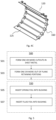
- Fig. 5 shows an example method of forming a spring foil 500 comprising forming one or more cutouts in sheet metal 501 , which are I-shaped cutouts; forming one or more out of plane retaining portions 503, which may be disposed at one or both ends of each cutout.
- the cutouts may be arranged to extend in a direction parallel to the axis of the bushing upon insertion within the bushing.
- the one or more retaining portions may be arranged to be disposed axially outside the radially inner surface of the bushing upon insertion of the spring foil within a bushing.
- Fig. 5 also shows an example method of forming a compliant radial bearing 550, which may be performed following the method of forming the spring foil 500, comprising the steps of: inserting the spring foil into the radially inner surface of the bushing 505; and inserting the fluid foil into the radially inner surface of the spring foil 507.
- the method may further comprise inserting one or more fluid foil retaining members within grooves of the bushing thereby to retain the fluid foil and optionally also the spring foil within the bushing.
- a method of manufacturing the compliant radial bearing may comprise: forming one or more cutouts in sheet metal, e.g. as in Fig. 4A , inserting the sheet metal into a bushing; forming one or more retaining portions in the spring foil at axial end portions thereof.
- the retaining portions may be formed once the sheet metal been inserted into the bushing.
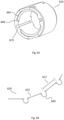
- Fig. 6A depicts an example of a bushing 610 having circumferentially oppositely disposed seats 665 that provide stop surfaces 668 preventing rotation of the spring foil by virtue of interaction between the retaining portions 160 of the spring foil and the stop surfaces 668 of the seats 665.
- Bushing 610 has axially-oriented grooves for receiving fluid foil retaining members therein.
- the depicted examples of the bushing seats show seats that are located at a position axially inside of an axial end surface of the bushing.
- the bushing seats may be located at axial ends of the radial inner surface of the bushing and axially inside the axial end surfaces of the bushing. This prevents the retaining portions extending axially beyond the end surface of the bushing, improving handling characteristics of the bearing.
- Fig. 6B depicts an example of a portion of a spring foil 620 suitable for use in the bushing of Fig. 6A .
- strips 625 are provided with a uniform circumferential length 627, facilitating manufacturing simplicity however a non-uniform circumferential length may be provided offering the capability to vary the loading characteristics of the spring foil in a circumferential direction.
- Fig. 7A depicts an example of an alternative bushing 710 having seat 765 without stop surfaces. Rotation of the spring foil 720 is prevented by clamping an end clamping region 768 of the spring foil 720 using one or spring foil retaining members 170, 180. This arrangement facilitates reduced manufacturing complexity of the bushing.
- the spring foil is provided with an axially oriented clamping hook 768 at an end thereof to be received within an axially disposed groove 175 of the bushing 710 for receiving a retaining member, e.g. a fluid foil retaining member.
- a retaining member e.g. a fluid foil retaining member.
- the spring foil can be prevented from rotation within the bushing using the one or more retaining members, which may be fluid foil retaining members used to clamp the fluid foil in place.
- a retaining member may be provided for insertion into a groove for receiving the retaining member to secure the fluid foil and/or the spring foil.
- Fig. 7B shows a spring foil 720 comprising an axially oriented hook 768 comprising a radially outer concavity.
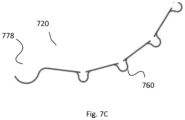
- Fig. 7C shows a spring foil 720 having an axially oriented hook 778 comprising a radially inner concavity.
- each of the examples disclosed herein, including the claimed examples, may be provided in a gas turbine system, e.g. a micro turbine system, comprising the fluid foil radial bearing according to any one example.
- a gas turbine system e.g. a micro turbine system
- Employing such a fluid foil radial bearing in a gas turbine system provides a gas turbine system offering improved management of frictional losses and heat
Landscapes
- Engineering & Computer Science (AREA)
- General Engineering & Computer Science (AREA)
- Mechanical Engineering (AREA)
- Physics & Mathematics (AREA)
- Fluid Mechanics (AREA)
- Support Of The Bearing (AREA)
- Sliding-Contact Bearings (AREA)
Description
- The subject matter disclosed herein relates generally to compliant foil radial bearings.
- Micro turbines may be utilized in distributed energy resources and may employ a compressor, combustor, turbine and electric generator thereby to convert fuel into a local source of electric power. Their small footprint, high rotational speeds and high operating temperatures render traditional bearings, such as oil-based hydrostatic bearings, impractical.
- Compliant fluid foil radial bearings utilize: a bushing; a compliant spring foil that conforms to the inner surface of the bushing; and a fluid top foil that conforms to the inner surface of the compliant spring foil, the inner surface of the fluid top foil for receiving a rotor.
- Prior to spin-up, gravitational forces acting on the rotor compress the fluid foil and spring foil between the rotor and inner surface of the bushing. Following spin-up, the creation of a thin layer of fluid between the non-rotating fluid foil and the rotating rotor results in the rotor, as it were, lifting off from the fluid foil, giving rise to a low friction hydrodynamic bearing, and, additionally, the transfer of fluid facilitates heat transfer.
- Compliant fluid foil radial bearings may therefore be employed in micro turbines to combat the impracticalities associated with other traditional forms of radial bearing given the high rotational speeds and operating temperatures.
- Existing fluid foil bearing designs like for example shown in
US 2014/219 590 A1 disclosing the preamble of claims 1 and 12, generally employ a corrugated spring foil and fastening mechanism between the spring foil and bushing resulting in excessive manufacturing complexity. Furthermore, the effectiveness at low revolutions per minute of such existing designs is sufficiently poor that excessive bearing wear is introduced during spin-up and even during post spin-up normal operation. The performances of such existing designs is overly dependent upon the manufacturing specifics associated with the spring foil. Finally, the scope for optimization of the friction characteristics of these existing designs is limited. - It is therefore desirable to provide a fluid foil bearing resolving one or more of the above-described deficiencies in existing designs.
- A first objective of the present disclosure is to provide a compliant foil radial bearing.
- A second objective of the present disclosure is to provide a method of manufacturing a spring foil for a compliant foil radial bearing.
- The present disclosure provides a compliant foil radial bearing comprising: a bushing comprising a bore defined therethrough; a spring foil arranged to conform to a radially inner surface of the bore; a fluid foil arranged to conform to a radially inner surface of the spring foil for rotatably receiving a rotor; wherein the spring foil comprises: a plurality of axially oriented strips; and a plurality of retaining portions arranged to extend axially and radially outside the radially inner surface of the bore, wherein adjacent ones of the plurality of axially oriented strips are interconnected by a respective one of the plurality of retaining portions, wherein each of the plurality of retaining portions is provided in the form of a loop.
- In one embodiment the strips are curved in the circumferential direction.
- In one embodiment the plurality of strips and fluid foil are arranged such that each strip contacts the radially inner surface of the bushing at first and second axially oriented bushing contact regions and contacts the fluid foil at an axially oriented fluid foil contact region in between the first and second axially oriented bushing contact regions.
- In one embodiment the circumferential spacing between the strips is non-uniform.
- In one embodiment the ratio between the circumferential width of each strip and a diameter of the bore is between 2 to 12.
- In one embodiment the bushing comprises a seat for receiving the plurality of retaining portions of the spring foil, and the seat is disposed axially inside an axial end surface of the bushing and comprises a plurality of stop surfaces for preventing circumferential displacement of the spring foil.
- In one embodiment the spring foil comprises first and second sets of retaining portions at opposite axial ends thereof.
- In one embodiment the compliant foil radial bearing further comprises a plurality of retention members arranged to fit within a plurality of corresponding grooves in the bushing, wherein the spring foil comprises a plurality of axially oriented retaining hooks arranged to wrap around the plurality of retention members when inserted in the plurality of corresponding grooves in the bushing.
- In one embodiment the compliant foil radial bearing further comprises first and second spring foil segments.
- The present disclosure also provides a method of manufacturing a spring foil for a compliant foil radial bearing, the spring foil comprising a plurality of axially oriented strips and a plurality of retaining portions, the method comprising: forming the spring foil from a sheet metal blank having cutouts between each of the plurality of axially oriented strips, wherein the cutouts are I-shaped cutouts comprising portions for axial orientation with perpendicular cross bar portions for circumferential orientation at each end thereof, wherein the cross bar portions are arranged at each axial end of the bushing, and wherein the spring foil has a plurality of retaining portions at one or both ends of each I-shaped cutout
- Disclosed arrangements are further described hereinafter by way of example and with reference to the accompanying drawings, in which:
-
Fig. 1 depicts an example of a compliant foil radial bearing in an exploded perspective view; -
Fig. 2 depicts the example compliant foil radial bearing ofFig. 1 from a direction parallel to the axis of the bushing; -
Fig. 3 depicts the interaction between the retaining portions and bushing in the example fluid foil radial bearing ofFig. 1 ; -
Fig. 4A depicts an example of a blank for forming a spring foil; -
Fig. 4B depicts an example of a flat spring foil ready for insertion within a bushing; -
Fig. 4C depicts an example of a curved spring foil ready for insertion within a bushing; -
Fig. 5 depicts an example of a method of forming a spring foil and a method of forming a compliant foil radial bearing; -
Figs. 6A and 6B depict a first example of a bushing and spring foil for use therewith; and -
Figs. 7A, 7B and7C depict a second example of a bushing and alternative spring foils for use therewith. -
Fig. 1 depicts an example of a compliant foil radial bearing 100 comprising abushing 110 comprising a bore defined therethrough, aspring foil fluid foil spring foil retaining portions 160 arranged to extend axially and radially outside the inner surface of the bore. - In the example of
Fig. 1 , the spring foil comprises first 120 and second 130 spring foil segments. Likewise the fluid foil comprises first 140 and second 150 fluid foil segments. This arrangement is commensurate with a two lobe radial bearing, however the disclosure herein is equally applicable to a one, three or other lobe bearing in which the spring foil and fluid foil comprise one, three or another number of segments. - With reference to the
spring foil Fig. 1 , it will be observed that theretaining portions 160 of the spring foil will extend axially and radially outside the bore of thebushing 110 when inserted into the bore of thebushing 110. - The inner surface of the bore may define a bore axis, bore inner surface radius and oppositely disposed bore inner surface axial ends. The one or more
retaining portions 160 may extend radially outside the bore inner surface radius and axially outside the bore inner surface axial ends, e.g. any one retaining portion may extend to a radius greater than the bore inner surface radius and may extend to an axis that is outside the axial region spanned by the bore inner surface axial ends. Theretaining portions 160 may comprise axially oppositely disposed retaining portions that extend radially and axially outside the inner surface of the bore. - The spring foil offers a resilient support for the fluid foil, both prior to, and during, the spin-up phase of operation of the bearing and also during normal operation thereof. Thus force acting in a direction radially outwards from the rotor may be transferred via the spring foil to the bushing inner surface.
- The fluid foil provides a surface for rotatably receiving a rotor and in use a thin rapidly moving fluid layer forms between the surface of the fluid foil and the rotor giving rise to a low friction environment within which the rotor can rotate. That the retaining portions extend outside the radial inner surface of the bore region including critical interacting surfaces serves to reduce performance dependence upon manufacturing specifics relating to the spring foil. The hydrodynamic nature of the fluid layer prevents excessive buildup of heat. Furthermore, relocating the retaining portions outside the critical interacting surface region facilitates increased control over the stiffness characteristics within the critical region by reducing interdependence between the stiffness characteristics within the critical region and the retention mechanism. These properties of the fluid foil radial bearing render the fluid foil radial bearing particularly suitable for use in high temperature high rotation applications such as in the case of micro turbines.
- In the example provided in
Fig. 1 ,retention members corresponding grooves 175 provided in thebushing 110 thereby to clamp the fluid foil segments following assembly. - Retaining
portions 160 of the spring foil are arranged so as to extend axially and radially outside the inner surface of the bore of thebushing 110. In the example provided inFig. 1 , eachspring foil segment - Thus the spring foil may be provided with one or more retaining portions arranged to be disposed at each axial end of the bushing. By providing a spring foil with one or more retaining portions at axially opposite ends thereof, the spring foil can be slotted into the bushing 110 and the axially opposed sets of retaining portions protrude axially and radially outside the radially inner surface of the
bushing 110 facilitating a secure fit therebetween and reducing the potential for axial displacement of the spring foil. - The
bushing 110 may be provided with aseat 165 for receiving one or more of the retaining portions of the spring foil. The bushing may be provided with one or more seats for receiving the one or more retaining portions of the spring foil. The bushing may be provided with one or more seats at each axial end thereof. -
Fig. 2 provides a front view of a compliant foil radial bearing. As shown in this example, axially-oriented lengths of thefluid foil segments foil retention members fluid foil segments grooves 175 provided within thebushing 110. - In the example of
Fig. 2 , there are provided first 165a and second 165b seats for receiving retainingportions 160 associated with the first 140 and second 150 fluid foil segments. - As shown in
Fig. 2 , the retaining portions extend axially and radially outside the inner surface of the bore of thebushing 110. - By positioning the retaining portions of the spring foil axially and radially outside the inner surface of the bore of the
bushing 110, there is facilitated a greatly simplified manufacturing of thebushing 110 since the retaining portions do not need to be supported by structural features of the inner surface of thebushing 110. - Furthermore, the positioning of the retaining portions outside the critical inner surface of the bore of the
bushing 110 reduces the impact of the retention between the spring foil and bushing on performance of the bearing, which results in reduced sensitivity in respect of bearing performance upon manufacturing specifics. - Whilst the figures show the provision of a seat for receiving the retaining portions of the spring foil, the retention mechanism disclosed in the present application would equally apply in the case of a bushing provided without a seat. In this case the retaining portions would sit on the axial outside ends of the bushing.
-
Fig. 3 provides a close-up view of the interaction between theretention portions 160 of the spring foil and thebushing 110. - In the depicted example, the retaining portions are provided in the form of loops. The loops are arranged to extend radially outwards from the inner surface of the bore of the
bushing 110. Providing the retaining portions in the form of loops has been shown to facilitate improved isolation between the retention mechanism and the critical surfaces within the bearing relating to performance. - Turning back to
Fig. 1 , in this example the spring foil comprises axially oriented strips. The strips may be arranged so as to be co-axially disposed with the axis of the bore. In the two segment example shown,first segment 120 comprisesaxial strips 125 andsecond segment 130 comprisesaxial strips 135. -
Fig. 1 depicts aspring foil segment 120 comprising a plurality ofstrips 125 that are interconnected by retainingportions 160. Connectingstrips 125 using the retainingportions 160 facilitates independent tunable stiffness and resilience of each strip. - An aspect of the stiffness and resilience facilitated by a spring foil comprising one or more strips will be explained in detail with reference to
Fig. 3 . - With the
spring foil 120 conforming to the radially inner surface of the bore of thebushing 110, each strip contacts the radially inner surface of the bore of thebushing 110 at circumferentially opposing radially outer contact regions on the strips. In between these circumferentially opposing contact regions of the strips,fluid foil 140 contacts the radially inner surface of the strip of thespring foil 120. In this way, the strips may be considered as beams supported at the circumferentially opposing radially outer contact regions, with thefluid foil 140 deforming the beams in between the circumferentially opposing contact regions by contacting the strip at a radially inner surface thereof. The contact between each strip and bushing and each strip and the fluid foil may be axially oriented contact regions. These axially oriented contact regions may be line contacts or may be colinear point contacts along the axis. Such contact between the spring foil and fluid foil has been found to provide excellent bearing performance even at low revolutions per minute by increasing coulomb friction. - The above-described interconnection between the spring foil, bushing and fluid foil facilitates excellent bearing performance even at low revolutions per minute by providing optimal stiffness characteristics. Furthermore, the establishing of pin-to-pin beams in the strips for supporting the fluid foil offers the potential to vary the spring foil stiffness characteristic in the circumferential direction. This can be particularly advantageous mindful that owing to gravitational forces and other factors, loading in a fluid foil radial bearing tends to vary in a circumferential direction. This variation may be compensated for by varying the physical characteristics of the strips in a circumferential direction.
- The strips may be curved in a circumferential direction. For example, the strips may be curved so as to present radially outwardly facing concavities. This may be synergistic with the above-described form of contact between the strip, fluid foil and bushing and facilitates greater control over the stiffness characteristics and the contact regions.
-
Fig. 4A depicts a blank 420 comprising sheet-metal having cutouts 422 from which the spring foil may be formed. In this example, there is provided auniform spacing 424 betweenstrips 425. This facilitates manufacturing simplicity. However, for the reasons outlined above, providing non-uniform spacing between strips can be advantageous, offering the potential to vary the resilience profile in a circumferential direction. - The
spring foil 420 comprises l-shapedcutouts 422, e.g. cutouts comprising portions for axial orientation with perpendicular cross bar portions for circumferential orientation at each end thereof. The cross bar portions are arranged to be disposed at each axial end of the bushing. Forming l-shapedcutouts 422 offers a simplistic manufacturing method for forming aspring foil 420 having retaining portions at one or both ends of each l-shaped cutout, the retaining portions being arranged to be disposed axially and radially outwardly from the inner surface of the bore. - The bushing may be provided with a length (L) between 0.5 to 3 times a diameter (D) of the bore of the bushing, i.e. L/D=0.5 to 3, and the diameter (D) may set to be between 15 and 25 mm or between 20 to 23 mm. The ratio between a diameter of the bore of the bushing (D) and the circumferential width of each strip (W) - see indication of W' showing strip width in
Fig. 4A , i.e. the width of each strip between first and second axially oriented ends thereof, may be set to be between 2 to 12, i.e. D/W = 2 to 12. The strip width may be between 2mm to 5mm. Providing a strip width within this range has been found to provide optimal stiffness characteristics facilitating excellent bearing performance particularly for use of a compliant radial bearing within a microturbine. The thickness of the foil may be set to between 0.01 mm to 0.2mm. It has been identified that the aforementioned dimensions provide an air bearing having excellent performance characteristics for a range of applications. -
Fig. 4A depicts aspacing 426 between the strips and retainingportions 160. Thisspacing 426 may correspond with the axial width of the circumferentially disposed cutout portions. When assembled, thisspacing 426 is axially oriented and improves isolation between the retention mechanism and thestrips 425 located within the bore. Furthermore, independence between the loading characteristics of thestrips 425 is improved. -
Fig. 4B depicts aspring foil 120 formed from blank 420. The one ormore retaining portions 160 have been formed at ends of the cutout portions in betweenstrips 125 and are arranged so as to be disposed axially and radially outside the radially inner surface of the bushing upon insertion therein. The one ormore retaining portions 160 may be formed in the blank 420 by forming out of plane bends or loops at one or both ends of thecutouts 422 arranged for axial orientation with the bushing. -
Fig. 4B shows aspring foil 160 formed from sheet metal comprising l-shapedcutouts 422 and out ofplane retaining portions 160 ready for insertion within a bushing. Such a spring foil facilitates significantly simplified manufacturing as compared to existing spring foil designs requiring complicated corrugation techniques, etc. - Optionally, as shown in
Fig. 4C , the substantially flat sheet metal may be curved in accordance with the shape of the radially inner surface of the bushing, prior to insertion within the bushing. Whilst omitting this step simplifies manufacturing, curving the flat sheet metal in this way during manufacturing of the spring foil facilitates reduced performance sensitivity to insertion of the spring foil within the bushing. -
Fig. 5 shows an example method of forming aspring foil 500 comprising forming one or more cutouts insheet metal 501 , which are I-shaped cutouts; forming one or more out ofplane retaining portions 503, which may be disposed at one or both ends of each cutout. The cutouts may be arranged to extend in a direction parallel to the axis of the bushing upon insertion within the bushing. The one or more retaining portions may be arranged to be disposed axially outside the radially inner surface of the bushing upon insertion of the spring foil within a bushing. -
Fig. 5 also shows an example method of forming a compliantradial bearing 550, which may be performed following the method of forming thespring foil 500, comprising the steps of: inserting the spring foil into the radially inner surface of thebushing 505; and inserting the fluid foil into the radially inner surface of thespring foil 507. Although not shown, the method may further comprise inserting one or more fluid foil retaining members within grooves of the bushing thereby to retain the fluid foil and optionally also the spring foil within the bushing. - Although not shown, a method of manufacturing the compliant radial bearing may comprise: forming one or more cutouts in sheet metal, e.g. as in
Fig. 4A , inserting the sheet metal into a bushing; forming one or more retaining portions in the spring foil at axial end portions thereof. Thus the retaining portions may be formed once the sheet metal been inserted into the bushing. -
Fig. 6A depicts an example of abushing 610 having circumferentially oppositely disposedseats 665 that providestop surfaces 668 preventing rotation of the spring foil by virtue of interaction between the retainingportions 160 of the spring foil and the stop surfaces 668 of theseats 665.Bushing 610 has axially-oriented grooves for receiving fluid foil retaining members therein. - The depicted examples of the bushing seats show seats that are located at a position axially inside of an axial end surface of the bushing. The bushing seats may be located at axial ends of the radial inner surface of the bushing and axially inside the axial end surfaces of the bushing. This prevents the retaining portions extending axially beyond the end surface of the bushing, improving handling characteristics of the bearing.
-
Fig. 6B depicts an example of a portion of aspring foil 620 suitable for use in the bushing ofFig. 6A . As shown, strips 625 are provided with a uniformcircumferential length 627, facilitating manufacturing simplicity however a non-uniform circumferential length may be provided offering the capability to vary the loading characteristics of the spring foil in a circumferential direction. -
Fig. 7A depicts an example of analternative bushing 710 havingseat 765 without stop surfaces. Rotation of thespring foil 720 is prevented by clamping anend clamping region 768 of thespring foil 720 using one or springfoil retaining members - In the example of
Fig. 7B , the spring foil is provided with an axially oriented clampinghook 768 at an end thereof to be received within an axially disposedgroove 175 of thebushing 710 for receiving a retaining member, e.g. a fluid foil retaining member. In this way the spring foil can be prevented from rotation within the bushing using the one or more retaining members, which may be fluid foil retaining members used to clamp the fluid foil in place. Thus a retaining member may be provided for insertion into a groove for receiving the retaining member to secure the fluid foil and/or the spring foil. -
Fig. 7B shows aspring foil 720 comprising an axially orientedhook 768 comprising a radially outer concavity. -
Fig. 7C shows aspring foil 720 having an axially orientedhook 778 comprising a radially inner concavity. - Each of the examples disclosed herein, including the claimed examples, may be provided in a gas turbine system, e.g. a micro turbine system, comprising the fluid foil radial bearing according to any one example. Employing such a fluid foil radial bearing in a gas turbine system provides a gas turbine system offering improved management of frictional losses and heat
- It will be recognized that the examples disclosed herein are not limiting and are capable of numerous modifications and substitutions. The invention is defined by the appended claims.
Claims (12)
- A compliant foil radial bearing (100) comprising:a bushing (110) comprising a bore defined therethrough;a spring foil (120, 130) arranged to conform to a radially inner surface of the bore;a fluid foil (140, 150) arranged to conform to a radially inner surface of the spring foil for rotatably receiving a rotor;wherein the spring foil comprises:a plurality of axially oriented strips (125); anda plurality of retaining portions (160) arranged to extend axially and radially outside the radially inner surface of the bore (110)characterized in thatadjacent ones of the plurality of axially oriented strips (125) are interconnected by a respective one of the plurality of retaining portions (160), wherein each of the plurality of retaining portions is provided in the form of a loop.
- The compliant foil radial bearing (100) according to claim 1, wherein:
the strips (125) are curved in the circumferential direction. - The compliant foil radial bearing (100) according to claim 1 or 2, wherein:
the plurality of strips (125) and fluid foil (140) are arranged such that each strip (125) contacts the radially inner surface of the bushing (110) at first and second axially oriented bushing contact regions and contacts the fluid foil (140) at an axially oriented fluid foil contact region in between the first and second axially oriented bushing contact regions. - The compliant foil radial bearing (100) according to any one of claims 1 to 3, wherein:
the circumferential spacing between the strips (125) is non-uniform. - The compliant foil radial bearing (100) according to any one of claims 1 to 4, wherein:
the ratio between the circumferential width of each strip (125) and a diameter of the bore is between 2 to 12. - The compliant foil radial bearing (100) according to any preceding claim, wherein:
the bushing comprises a seat (165) for receiving the plurality of retaining portions (160) of the spring foil (120). - The compliant foil radial bearing (100) according to claim 6, wherein:
the seat (165) is disposed axially inside an axial end surface of the bushing. - The compliant foil radial bearing (100) according to claim 6 or 7, wherein:
the seat (165) comprises a plurality of stop surfaces for preventing circumferential displacement of the spring foil (120). - The compliant foil radial bearing (100) according to any preceding claim, wherein:
the spring foil (120) comprises first and second sets of retaining portions at opposite axial ends thereof. - The compliant foil radial bearing (100) according to any preceding claim, comprising:
a plurality of retention members (170, 180) arranged to fit within a plurality of corresponding grooves (175) in the bushing (110), wherein:
the spring foil (120) comprises a plurality of axially oriented retaining hooks (778) arranged to wrap around the plurality of retention members when inserted in the plurality of corresponding grooves in the bushing. - The compliant foil radial bearing (100) according to any preceding claim, comprising: first and second spring foil segments (120, 130).
- A method of manufacturing a spring foil (120, 130) for a compliant foil radial bearing (100) as claimed in any of claims 1 to 11, the spring foil (120, 130) comprising a plurality of axially oriented strips (125) and a plurality of retaining portions (160), the method comprising:forming the spring foil from a sheet metal blank having cutouts (422) between each of the plurality of axially oriented strips,wherein the cutouts (422) are I-shaped cutouts (422) comprising portions for axial orientation with perpendicular cross bar portions for circumferential orientation at each end thereof,wherein the cross bar portions are arranged at each axial end of the bushing (110), and wherein the spring foil (120, 130) has the plurality of retaining portions at one or both ends of each I-shaped cutout (422).
Priority Applications (1)
| Application Number | Priority Date | Filing Date | Title |
|---|---|---|---|
| PL19716084.9T PL3931454T3 (en) | 2019-03-22 | 2019-03-22 | Compliant foil radial bearing |
Applications Claiming Priority (1)
| Application Number | Priority Date | Filing Date | Title |
|---|---|---|---|
| PCT/EP2019/057313 WO2020192874A1 (en) | 2019-03-22 | 2019-03-22 | Compliant foil radial bearing |
Publications (4)
| Publication Number | Publication Date |
|---|---|
| EP3931454A1 EP3931454A1 (en) | 2022-01-05 |
| EP3931454B1 true EP3931454B1 (en) | 2023-06-07 |
| EP3931454C0 EP3931454C0 (en) | 2023-06-07 |
| EP3931454B8 EP3931454B8 (en) | 2023-07-12 |
Family
ID=66092295
Family Applications (1)
| Application Number | Title | Priority Date | Filing Date |
|---|---|---|---|
| EP19716084.9A Active EP3931454B8 (en) | 2019-03-22 | 2019-03-22 | Compliant foil radial bearing |
Country Status (8)
| Country | Link |
|---|---|
| US (1) | US12006972B2 (en) |
| EP (1) | EP3931454B8 (en) |
| JP (1) | JP7433413B2 (en) |
| KR (1) | KR102763309B1 (en) |
| CN (1) | CN114008338A (en) |
| ES (1) | ES2954565T3 (en) |
| PL (1) | PL3931454T3 (en) |
| WO (1) | WO2020192874A1 (en) |
Families Citing this family (2)
| Publication number | Priority date | Publication date | Assignee | Title |
|---|---|---|---|---|
| CN113710908B (en) * | 2019-04-04 | 2023-07-21 | 株式会社Ihi | Radial Foil Bearings |
| CN114857165B (en) * | 2022-06-10 | 2025-11-28 | 北京华升宜能科技有限公司 | Floating ring gas dynamic pressure radial bearing |
Family Cites Families (16)
| Publication number | Priority date | Publication date | Assignee | Title |
|---|---|---|---|---|
| CA1141807A (en) | 1979-06-11 | 1983-02-22 | Giridhari L. Agrawal | Foil bearing mounting |
| US4262975A (en) | 1979-10-01 | 1981-04-21 | Mechanical Technology Incorporated | Compliant journal bearing with angular stiffness gradient |
| JPS60175914U (en) * | 1984-04-30 | 1985-11-21 | 株式会社島津製作所 | oil bearing |
| US5116143A (en) * | 1990-12-20 | 1992-05-26 | Allied-Signal Inc. | High load capacity journal foil bearing |
| US5228785A (en) * | 1990-12-20 | 1993-07-20 | Allied-Signal, Inc. | Stepped foil journal foil bearing |
| US5427455A (en) * | 1994-04-18 | 1995-06-27 | Bosley; Robert W. | Compliant foil hydrodynamic fluid film radial bearing |
| JP4935702B2 (en) * | 2008-02-05 | 2012-05-23 | 株式会社島津製作所 | Dynamic pressure gas bearing mounting structure |
| KR101068542B1 (en) * | 2009-08-31 | 2011-09-28 | 주식회사 뉴로스 | Journal Foil Air Bearings |
| CN101709747A (en) * | 2009-11-17 | 2010-05-19 | 西安交通大学 | Foil dynamical pressure radial air journal bearing with backward wave foil support |
| US8414191B2 (en) | 2010-03-19 | 2013-04-09 | GM Global Technology Operations LLC | Keyless/grooveless foil bearing with fold over tab |
| JP5862186B2 (en) * | 2011-10-13 | 2016-02-16 | 株式会社Ihi | Radial foil bearing |
| JP6136135B2 (en) * | 2012-07-18 | 2017-05-31 | 株式会社Ihi | Radial foil bearing |
| CN102797746A (en) | 2012-08-29 | 2012-11-28 | 哈尔滨工业大学 | Lubricating-oil leafy foil bearing with changeable pitch supported by bump foil |
| CN103423299B (en) * | 2013-08-02 | 2015-09-30 | 湖南大学 | A kind of air hydrodynamic bearing with the overlap joint type compliant foil that radially distributes |
| WO2015026655A1 (en) * | 2013-08-20 | 2015-02-26 | Borgwarner Inc. | Air bearing arrangement |
| JP2019019914A (en) * | 2017-07-19 | 2019-02-07 | Ntn株式会社 | Foil bearing |
-
2019
- 2019-03-22 ES ES19716084T patent/ES2954565T3/en active Active
- 2019-03-22 JP JP2022504325A patent/JP7433413B2/en active Active
- 2019-03-22 WO PCT/EP2019/057313 patent/WO2020192874A1/en not_active Ceased
- 2019-03-22 US US17/440,608 patent/US12006972B2/en active Active
- 2019-03-22 KR KR1020217033238A patent/KR102763309B1/en active Active
- 2019-03-22 EP EP19716084.9A patent/EP3931454B8/en active Active
- 2019-03-22 PL PL19716084.9T patent/PL3931454T3/en unknown
- 2019-03-22 CN CN201980096599.4A patent/CN114008338A/en active Pending
Also Published As
| Publication number | Publication date |
|---|---|
| EP3931454A1 (en) | 2022-01-05 |
| JP2022534128A (en) | 2022-07-27 |
| JP7433413B2 (en) | 2024-02-19 |
| US12006972B2 (en) | 2024-06-11 |
| EP3931454B8 (en) | 2023-07-12 |
| WO2020192874A1 (en) | 2020-10-01 |
| US20220186774A1 (en) | 2022-06-16 |
| PL3931454T3 (en) | 2023-09-25 |
| ES2954565T3 (en) | 2023-11-23 |
| KR20210141567A (en) | 2021-11-23 |
| KR102763309B1 (en) | 2025-02-07 |
| CN114008338A (en) | 2022-02-01 |
| EP3931454C0 (en) | 2023-06-07 |
Similar Documents
| Publication | Publication Date | Title |
|---|---|---|
| EP2740951B1 (en) | Thrust foil bearing | |
| EP2937584B1 (en) | Foil bearing | |
| CN110107590B (en) | Foil bearing for high-speed rotor | |
| WO1997002437A1 (en) | Hybrid foil/magnetic bearing | |
| US12006972B2 (en) | Compliant foil radial bearing | |
| CN114458687B (en) | Elastic foil dynamic pressure air-float radial bearing, motor and air compressor | |
| EP3994367B1 (en) | Compliant foil thrust bearing | |
| JP2013044394A (en) | Thrust foil bearing | |
| EP3931455B1 (en) | Compliant foil radial bearing | |
| US6450768B2 (en) | Axial thermal medium delivery tubes and retention plates for a gas turbine rotor | |
| WO2018116740A1 (en) | Foil bearing | |
| EP3323980B1 (en) | Gas turbine | |
| US11193538B2 (en) | Bearing cage assembly including stiffening ring | |
| EP4107399A1 (en) | A retaining element, a shaft assembly and methods for assembling or disassembling the shaft assembly | |
| CN116498646B (en) | A gas dynamic pressure bearing with fin-type support foil | |
| US11125273B1 (en) | Bearing cage assembly including metal shell | |
| JP2025114183A (en) | Electric motor rotor and manufacturing method thereof | |
| KR20240062521A (en) | Air Bearing For Turbomachinery | |
| JP2023180098A5 (en) | ||
| JPH09512084A (en) | Flexible foil hydrodynamic fluid film radial bearing |
Legal Events
| Date | Code | Title | Description |
|---|---|---|---|
| STAA | Information on the status of an ep patent application or granted ep patent |
Free format text: STATUS: UNKNOWN |
|
| STAA | Information on the status of an ep patent application or granted ep patent |
Free format text: STATUS: THE INTERNATIONAL PUBLICATION HAS BEEN MADE |
|
| PUAI | Public reference made under article 153(3) epc to a published international application that has entered the european phase |
Free format text: ORIGINAL CODE: 0009012 |
|
| STAA | Information on the status of an ep patent application or granted ep patent |
Free format text: STATUS: REQUEST FOR EXAMINATION WAS MADE |
|
| 17P | Request for examination filed |
Effective date: 20210927 |
|
| AK | Designated contracting states |
Kind code of ref document: A1 Designated state(s): AL AT BE BG CH CY CZ DE DK EE ES FI FR GB GR HR HU IE IS IT LI LT LU LV MC MK MT NL NO PL PT RO RS SE SI SK SM TR |
|
| DAV | Request for validation of the european patent (deleted) | ||
| DAX | Request for extension of the european patent (deleted) | ||
| STAA | Information on the status of an ep patent application or granted ep patent |
Free format text: STATUS: EXAMINATION IS IN PROGRESS |
|
| 17Q | First examination report despatched |
Effective date: 20220830 |
|
| GRAP | Despatch of communication of intention to grant a patent |
Free format text: ORIGINAL CODE: EPIDOSNIGR1 |
|
| STAA | Information on the status of an ep patent application or granted ep patent |
Free format text: STATUS: GRANT OF PATENT IS INTENDED |
|
| INTG | Intention to grant announced |
Effective date: 20221216 |
|
| GRAS | Grant fee paid |
Free format text: ORIGINAL CODE: EPIDOSNIGR3 |
|
| GRAA | (expected) grant |
Free format text: ORIGINAL CODE: 0009210 |
|
| STAA | Information on the status of an ep patent application or granted ep patent |
Free format text: STATUS: THE PATENT HAS BEEN GRANTED |
|
| GRAT | Correction requested after decision to grant or after decision to maintain patent in amended form |
Free format text: ORIGINAL CODE: EPIDOSNCDEC |
|
| AK | Designated contracting states |
Kind code of ref document: B1 Designated state(s): AL AT BE BG CH CY CZ DE DK EE ES FI FR GB GR HR HU IE IS IT LI LT LU LV MC MK MT NL NO PL PT RO RS SE SI SK SM TR |
|
| REG | Reference to a national code |
Ref country code: GB Ref legal event code: FG4D |
|
| REG | Reference to a national code |
Ref country code: CH Ref legal event code: PK Free format text: BERICHTIGUNG B8 Ref country code: CH Ref legal event code: EP Ref country code: AT Ref legal event code: REF Ref document number: 1575912 Country of ref document: AT Kind code of ref document: T Effective date: 20230615 |
|
| REG | Reference to a national code |
Ref country code: DE Ref legal event code: R096 Ref document number: 602019030136 Country of ref document: DE |
|
| RAP4 | Party data changed (patent owner data changed or rights of a patent transferred) |
Owner name: BLADON JETS HOLDINGS LIMITED |
|
| U01 | Request for unitary effect filed |
Effective date: 20230629 |
|
| U07 | Unitary effect registered |
Designated state(s): AT BE BG DE DK EE FI FR IT LT LU LV MT NL PT SE SI Effective date: 20230711 |
|
| REG | Reference to a national code |
Ref country code: LT Ref legal event code: MG9D |
|
| REG | Reference to a national code |
Ref country code: NO Ref legal event code: T2 Effective date: 20230607 |
|
| PG25 | Lapsed in a contracting state [announced via postgrant information from national office to epo] |
Ref country code: RS Free format text: LAPSE BECAUSE OF FAILURE TO SUBMIT A TRANSLATION OF THE DESCRIPTION OR TO PAY THE FEE WITHIN THE PRESCRIBED TIME-LIMIT Effective date: 20230607 Ref country code: HR Free format text: LAPSE BECAUSE OF FAILURE TO SUBMIT A TRANSLATION OF THE DESCRIPTION OR TO PAY THE FEE WITHIN THE PRESCRIBED TIME-LIMIT Effective date: 20230607 Ref country code: GR Free format text: LAPSE BECAUSE OF FAILURE TO SUBMIT A TRANSLATION OF THE DESCRIPTION OR TO PAY THE FEE WITHIN THE PRESCRIBED TIME-LIMIT Effective date: 20230908 |
|
| PG25 | Lapsed in a contracting state [announced via postgrant information from national office to epo] |
Ref country code: SK Free format text: LAPSE BECAUSE OF FAILURE TO SUBMIT A TRANSLATION OF THE DESCRIPTION OR TO PAY THE FEE WITHIN THE PRESCRIBED TIME-LIMIT Effective date: 20230607 |
|
| PG25 | Lapsed in a contracting state [announced via postgrant information from national office to epo] |
Ref country code: IS Free format text: LAPSE BECAUSE OF FAILURE TO SUBMIT A TRANSLATION OF THE DESCRIPTION OR TO PAY THE FEE WITHIN THE PRESCRIBED TIME-LIMIT Effective date: 20231007 |
|
| PG25 | Lapsed in a contracting state [announced via postgrant information from national office to epo] |
Ref country code: SM Free format text: LAPSE BECAUSE OF FAILURE TO SUBMIT A TRANSLATION OF THE DESCRIPTION OR TO PAY THE FEE WITHIN THE PRESCRIBED TIME-LIMIT Effective date: 20230607 Ref country code: SK Free format text: LAPSE BECAUSE OF FAILURE TO SUBMIT A TRANSLATION OF THE DESCRIPTION OR TO PAY THE FEE WITHIN THE PRESCRIBED TIME-LIMIT Effective date: 20230607 Ref country code: RO Free format text: LAPSE BECAUSE OF FAILURE TO SUBMIT A TRANSLATION OF THE DESCRIPTION OR TO PAY THE FEE WITHIN THE PRESCRIBED TIME-LIMIT Effective date: 20230607 Ref country code: IS Free format text: LAPSE BECAUSE OF FAILURE TO SUBMIT A TRANSLATION OF THE DESCRIPTION OR TO PAY THE FEE WITHIN THE PRESCRIBED TIME-LIMIT Effective date: 20231007 |
|
| REG | Reference to a national code |
Ref country code: DE Ref legal event code: R097 Ref document number: 602019030136 Country of ref document: DE |
|
| PLBE | No opposition filed within time limit |
Free format text: ORIGINAL CODE: 0009261 |
|
| STAA | Information on the status of an ep patent application or granted ep patent |
Free format text: STATUS: NO OPPOSITION FILED WITHIN TIME LIMIT |
|
| U20 | Renewal fee for the european patent with unitary effect paid |
Year of fee payment: 6 Effective date: 20240401 |
|
| 26N | No opposition filed |
Effective date: 20240308 |
|
| PG25 | Lapsed in a contracting state [announced via postgrant information from national office to epo] |
Ref country code: MC Free format text: LAPSE BECAUSE OF FAILURE TO SUBMIT A TRANSLATION OF THE DESCRIPTION OR TO PAY THE FEE WITHIN THE PRESCRIBED TIME-LIMIT Effective date: 20230607 |
|
| PG25 | Lapsed in a contracting state [announced via postgrant information from national office to epo] |
Ref country code: MC Free format text: LAPSE BECAUSE OF FAILURE TO SUBMIT A TRANSLATION OF THE DESCRIPTION OR TO PAY THE FEE WITHIN THE PRESCRIBED TIME-LIMIT Effective date: 20230607 |
|
| U1N | Appointed representative for the unitary patent procedure changed after the registration of the unitary effect |
Representative=s name: VALET PATENT SERVICES LIMITED; DE |
|
| PG25 | Lapsed in a contracting state [announced via postgrant information from national office to epo] |
Ref country code: IE Free format text: LAPSE BECAUSE OF NON-PAYMENT OF DUE FEES Effective date: 20240322 |
|
| PG25 | Lapsed in a contracting state [announced via postgrant information from national office to epo] |
Ref country code: IE Free format text: LAPSE BECAUSE OF NON-PAYMENT OF DUE FEES Effective date: 20240322 |
|
| U20 | Renewal fee for the european patent with unitary effect paid |
Year of fee payment: 7 Effective date: 20250317 |
|
| PGFP | Annual fee paid to national office [announced via postgrant information from national office to epo] |
Ref country code: ES Payment date: 20250402 Year of fee payment: 7 |
|
| PGFP | Annual fee paid to national office [announced via postgrant information from national office to epo] |
Ref country code: CH Payment date: 20250401 Year of fee payment: 7 |
|
| PG25 | Lapsed in a contracting state [announced via postgrant information from national office to epo] |
Ref country code: CY Free format text: LAPSE BECAUSE OF FAILURE TO SUBMIT A TRANSLATION OF THE DESCRIPTION OR TO PAY THE FEE WITHIN THE PRESCRIBED TIME-LIMIT; INVALID AB INITIO Effective date: 20190322 |
|
| PG25 | Lapsed in a contracting state [announced via postgrant information from national office to epo] |
Ref country code: HU Free format text: LAPSE BECAUSE OF FAILURE TO SUBMIT A TRANSLATION OF THE DESCRIPTION OR TO PAY THE FEE WITHIN THE PRESCRIBED TIME-LIMIT; INVALID AB INITIO Effective date: 20190322 |
|
| REG | Reference to a national code |
Ref country code: CH Ref legal event code: R17 Free format text: ST27 STATUS EVENT CODE: U-0-0-R10-R17 (AS PROVIDED BY THE NATIONAL OFFICE) Effective date: 20251006 |
|
| REG | Reference to a national code |
Ref country code: GB Ref legal event code: 732E Free format text: REGISTERED BETWEEN 20250925 AND 20251001 |
|
| REG | Reference to a national code |
Ref country code: ES Ref legal event code: PC2A Owner name: BLADON TECHNOLOGIES LIMITED Effective date: 20251215 |
|
| U1K | Transfer of rights of the unitary patent after the registration of the unitary effect |
Owner name: BLADON TECHNOLOGIES LIMITED; GB |
|
| REG | Reference to a national code |
Ref country code: CH Ref legal event code: U11 Free format text: ST27 STATUS EVENT CODE: U-0-0-U10-U11 (AS PROVIDED BY THE NATIONAL OFFICE) Effective date: 20260401 |
|
| PGFP | Annual fee paid to national office [announced via postgrant information from national office to epo] |
Ref country code: GB Payment date: 20260325 Year of fee payment: 8 |
|
| PGFP | Annual fee paid to national office [announced via postgrant information from national office to epo] |
Ref country code: NO Payment date: 20260327 Year of fee payment: 8 |
|
| PGFP | Annual fee paid to national office [announced via postgrant information from national office to epo] |
Ref country code: TR Payment date: 20260318 Year of fee payment: 8 |
|
| PGFP | Annual fee paid to national office [announced via postgrant information from national office to epo] |
Ref country code: CZ Payment date: 20260319 Year of fee payment: 8 |
|
| PGFP | Annual fee paid to national office [announced via postgrant information from national office to epo] |
Ref country code: PL Payment date: 20260318 Year of fee payment: 8 |
|
| U20 | Renewal fee for the european patent with unitary effect paid |
Year of fee payment: 8 Effective date: 20260325 |