EP3931074B1 - Leash assembly for a sports board - Google Patents
Leash assembly for a sports board Download PDFInfo
- Publication number
- EP3931074B1 EP3931074B1 EP20763479.1A EP20763479A EP3931074B1 EP 3931074 B1 EP3931074 B1 EP 3931074B1 EP 20763479 A EP20763479 A EP 20763479A EP 3931074 B1 EP3931074 B1 EP 3931074B1
- Authority
- EP
- European Patent Office
- Prior art keywords
- wing
- cuff assembly
- cord
- central section
- end portion
- Prior art date
- Legal status (The legal status is an assumption and is not a legal conclusion. Google has not performed a legal analysis and makes no representation as to the accuracy of the status listed.)
- Active
Links
Images



Classifications
-
- B—PERFORMING OPERATIONS; TRANSPORTING
- B63—SHIPS OR OTHER WATERBORNE VESSELS; RELATED EQUIPMENT
- B63B—SHIPS OR OTHER WATERBORNE VESSELS; EQUIPMENT FOR SHIPPING
- B63B34/00—Vessels specially adapted for water sports or leisure; Body-supporting devices specially adapted for water sports or leisure
- B63B34/60—Arrangements for towing, e.g. for use with water-skis or wakeboards
-
- B—PERFORMING OPERATIONS; TRANSPORTING
- B63—SHIPS OR OTHER WATERBORNE VESSELS; RELATED EQUIPMENT
- B63B—SHIPS OR OTHER WATERBORNE VESSELS; EQUIPMENT FOR SHIPPING
- B63B32/00—Water sports boards; Accessories therefor
- B63B32/70—Accessories not specially adapted for a particular type of board, e.g. paddings or buoyancy elements
- B63B32/73—Accessories not specially adapted for a particular type of board, e.g. paddings or buoyancy elements for tethering users or objects to the board, e.g. leashes
Definitions
- This disclosure generally relates to sports boards designed to support a rider during recreation, and in particular to leash assemblies for surfboards, boogie boards, stand-up paddle boards, and the like for tethering the sports board to a user's limb during recreation.
- surfboards may be equipped with a leg rope or leash, which serves to keep the surfboard associated with the user in the event the user becomes separated from the surfboard, either intentionally or unintentionally.
- Leashes as now in use, may consist of a length of rope, cord or similar material that is coupled at one end to a part of the surfboard, while the other end of the rope or cord is generally associated with or coupled to or in some way connected with a leg band, traditionally referred to as a cuff, which is secured around one leg of the board user/rider.
- leg rope or leash The purpose of using a leg rope or leash is to keep the surfboard attached to the ankle of the user/rider, but at the same time provide sufficient slack that the surfboard can be retained at a safe distance from the user/rider. Should the surfer fall whilst, for example, riding a wave, then the surfboard will not be swept away, allowing the surfer to quickly recover the surfboard and either proceed with the board to shore, or return to the take-off zone for further surfing.
- JP H09 76990 A describes a leash of a surf board, in which a fitting piece to the board is connected to an ankle strap to be fitted to a foot or a hand of a user by a cord. The connection of the ankle strap to the cord is attached/ detached by an emergency detaching means.
- WO 2017/181225 A1 describes a leash assembly for watercraft users with an elongate composite horn and extended base.
- the leash assembly can feature a low hydrodynamic drag rail saver, non-slip arrangement for the cuff and a pull tab release for the cuff.
- the invention relates to a cuff assembly as set out in the appended claim 1.
- the present disclosure provides cuff assemblies for use in sports board leashes, sports board leashes for use in conjunction with sports boards, and methods for securing the cuff assemblies of such sports boards.
- the invention describes a cuff assembly for a sports board leash, the cuff assembly including a central section that includes a precurved molded insert configured to connect to a cord of the sports board leash; a first wing attached to a first side of the central section; and a second wing attached to a second side of the central section; where the central section, first wing, and second wing have curvilinear upper and lower borders.
- the disclosure provides a cuff assembly for a sports board leash, the cuff assembly including a central section that includes a unitary molded insert that is precurved to complement a person's ankle, where the molded insert includes a horn that protrudes from an exterior surface of the central section and is configured to connect to a cord of the sports board leash; a first wing attached to a first side of the central section; and a second wing attached to a second side of the central section; where a maximum width of the central section is greater than a maximum width of either the first wing or the second wing, and the first wing and second wing are configured to overlap and fasten to each other to secure the cuff assembly around a person's limb portion.
- the disclosure provides a sports board leash including a cord having a first end portion and a second end portion; a cuff assembly connected to the first end of first end portion of the cord; and a sports board fastening device connected to the second portion of the cord.
- the cuff assembly includes a central section that includes a precurved molded insert that is connected to the first end portion of the cord; a first wing attached to a first side of the central section; and a second wing attached to a second side of the central section; where a maximum width of the central section is greater than a maximum width of either the first wing or the second wing, and the first wing and second wing are configured to overlap and fasten to each other to secure the cuff assembly around a person's limb portion.
- the disclosure provides a method of securing a cuff assembly for a sports board leash, where the cuff assembly includes a central section that includes a precurved molded insert connected to a first end of a cord of the sports board leash; a first wing attached to a first side of the central section; and a second wing attached to a second side of the central section; where a maximum width of the central section is greater than a maximum width of either the first wing or the second wing, and the first wing and second wing are configured to overlap and fasten to each other to secure the cuff assembly around a person's limb portion.
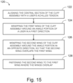
- the method of securing the cuff assembly includes aligning the central section of the cuff assembly with a user's Achilles tendon; wrapping the first wing around the ankle surface in a first direction; wrapping the second wing around the ankle surface in an opposite direction, so that the second wing overlaps the first wing; and fastening the second wing to the first wing where the wings overlap.
- a sports board leash in accordance with the present teachings, and/or its various components may, but are not required to, contain at least one of the structures, components, functionalities, and/or variations described, illustrated, and/or incorporated herein.
- process steps, structures, components, functionalities, and/or variations described, illustrated, and/or incorporated herein in connection with the present teachings may be included in other similar devices and methods, including being interchangeable between disclosed examples.
- the following description of various examples is merely illustrative in nature and is in no way intended to limit the disclosure, its application, or uses. Additionally, the advantages provided by the examples described below are illustrative in nature and not all examples provide the same advantages or the same degree of advantages.
- the sports board leashes of the present disclosure are particularly useful when used in conjunction with surfboards, boogie boards, and/or paddle boards.
- the disclosed board leashes may also be useful as a retention aid for any other sports board, such as snowboards, or even skis, where they may act as a supplement to, or a backup for, conventional bindings.
- the cuff assembly can be modified to be used over clothing and/or footwear, such as boots.
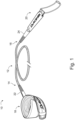
- Board leash 10 can include a cord 12 extending between a first end portion 14 and a second end portion 16 of cord 12.
- Board leash 10 can further include a cuff assembly 18 connected to first end portion 14, where cuff assembly 18 is configured to be coupled to a person's limb, and a board fastening device 20 that is connected to the second end portion 16, that is configured to be coupled to a sports board.
- Cord 12 can be attached to cuff assembly 18 and board fastening device 20 via any suitable connection.
- first end portion 14 of cord 12 is connected to cuff assembly 18 via a cord coupling swivel member 22, and second end portion 16 is similarly connected to board fastening device 20 via a cord coupling swivel member 24.
- cuff assembly 18 can be configured to fit around a portion of a user's limb, in order to secure the sports board leash (and therefore a connected sports board) securely attached to the user.
- Cuff assembly 18 is configured such that it can be secured to a variety of positions on a given user's limbs, including upper or lower arm, or upper or lower leg.
- cuff assembly 18 can be most advantageously configured to be attached to a user's lower leg portion. That is, cuff assembly 18, as manufactured, incorporates a degree of curl or curvature that is compatible with wrapping around and being secured to a lower leg portion, and in particular, compatible with wrapping and being secured to a user's ankle.
- cuff assembly 18 is described as configured to be secured to a user's ankle, it should be appreciated that cuff assembly 18 is not specifically intended to be secured around that portion of the ankle that incorporates one or more components of the ankle joint, as the presence of the cuff can in some cases interfere with the mobility of the ankle joint. Rather, cuff assembly 18 is typically configured to be wrapped around and secured to the user's lower leg below the calf yet above the malleoli (the bone prominences on each side of the ankle).
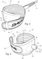
- cuff assembly 18 can include a central cuff section 26 that includes a precurved molded insert 28.
- Cuff assembly 18 further includes a first wing 30 that is attached to a first side 32 of central section 26, and a second wing 34 attached to a second side 36 of central section 26.
- First wing 30 and second wing 34 are configured to be overlapped and fastened to each other in order to secure cuff assembly 18 around a person's limb portion. More specifically, first wing 30 and second wing 34 of cuff assembly 18 can be configured to fasten to each other by first wrapping first wing 30 around the user's limb and then overlapping first wing 30 with second wing 34, and cuff assembly typically includes a closure mechanism 38.
- Any closure mechanism that can comfortably and securely retain cuff assembly 18 to a user's limb during the normal use of the associated sports board can be a suitable closure for the purposes of the disclosed cuff assembly.
- a hook-and-loop closure is employed as closure 38, a first component 40 of the hook-and-loop closure can be disposed on an outer surface 42 of first wing 30, and the complementary second component 44 of the hook-and-loop closure can be disposed on an inner surface 46 of second wing 34.
- first wing 30 is one or both of wider than second wing 34, and longer than second wing 34, preferably both wider and longer to provide a larger "target" for securing second wing 34, as is more clearly shown in Figs. 4-5 .
- Cuff assembly 18 can be precurved, that is a curve can be imparted to the materials making up cuff assembly 18 so that it exhibits a permanent curvature during manufacture, and so is therefore easier to fasten to a limb portion of a user than a cuff with no permanent precurved structure.
- the precurvature of cuff assembly 18 can be created during manufacture by one or more methods.
- portions of the cuff assembly, and in particular first wing 30 and second wing 34 can incorporate a plurality of fabric layers that can be manufactured together such that each wing has a memorized degree of curvature.
- cuff assembly 18 can be precurved due in part to an application of a curved heat press to one or more components of cuff assembly 18, or the cuff assembly as a whole during manufacture of the cuff assembly.
- the curvature imparted to cuff assembly 18 can help assist the user to fasten the cuff assembly to a limb portion. This may be particularly true where a component of the cuff assembly is both curved and stiffened, a stiffened cuff component is one that resists at least somewhat being flexed.
- central section 26 of cuff assembly 18 is stiffer, and more resistant to flexing, than either first wing 30 or second wing 34.
- second wing 34 can be stiffer, and more resistant to flexing, than first wing 30.
- central section 26 is reinforced and maintained by molded insert 28.
- the curve of molded insert 28 is shaped and sized so as to be complementary to the rear surface of a user's ankle.
- center section 26 of cuff assembly is configured to be placed against the rear surface of the user's ankle, adjacent to the user's Achilles tendon, and then secured in that position.
- cuff assembly 18 is therefore configured so that a maximum width 48 of central section 26 is greater than a maximum width 50 of first wing 30 or a maximum width 52 of second wing 34, placing greater support at and around the user's Achilles tendon. This may be particularly advantageous as central section 26 serves as the attachment point of cord 12 of sports board leash 10, and may therefore be the recipient of stresses and shocks during use.
- first wing 30 and second wing 34 can incorporate the region of maximum width for each wing, and each wing may then taper in width at both ends.
- cuff assembly 18 may exhibit an overall profile that exhibits several compound curves, that is, both an upper edge 54 and a lower edge 56 may be curvilinear, or consisting of a curved line or lines, which can provide an attractive appearance while the cuff regions exhibiting increased width can further provide additional support to the cuff assembly, helping to comfortably distribute stress and shock more evenly around the cuff for a more comfortable and effective anatomical fit.
- an inner surface 58 of first wing 30 can be functionalized by the presence of an applied pattern 60 of a frictional material 62 that serves to reduce slipping when cuff assembly 18 is wet.
- applied pattern 60 can include simple arcuate forms, or applied pattern 60 can include a repeating pattern of frictional pads across some or all of inner surface 58.
- a variety of frictional materials can be suitable for forming applied pattern 60, however the use of silicone polymer in particular can provide enhanced grip when wet while still exhibiting sufficient resilience to provide comfort.
- Precurved molded insert 28 typically is typically injection molded as a unitary piece of polymer. Molded insert 28 is typically retained within central section 26 of cuff assembly 18, disposed between component layers of the cuff assembly excepting for a horn portion 64 that projects from an outer surface 66 of central section 26.
- molded horn portion 64 can have a height in a range of 30 mm to 50 mm, and a width in a range of 60 mm to 90 mm.
- Horn portion 64 can be configured to connect to cord 12 of sports board leash 10. More specifically, horn portion 64 can be configured to attach a cord coupling structure such as cord coupling swivel member 22, which secures cuff assembly 18 to cord 12.
- molded horn portion 64 defines a hole 67 configured to receiving a cord connection device. Molded horn portion 64 serves to defines a central axis 68 through hole 67 that is coextensive with the direction of cord 12 when attached to molded horn portion 64.
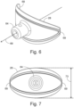
- molded insert 28 is shown in Figs. 6-9 .
- typically molded insert 28 displays an overall outline that is wider than it is tall, and molded insert 28 is curved to fit comfortably against a surface of a user's limb.
- the sides 69 of molded insert 28 curve inwardly and around a limb axis 70 that is defined by its alignment with the user's limb where cuff assembly 18 is worn, such that limb axis 70 extends perpendicularly to central axis 68.
- Molded insert 28 is wider within the plane defined by cuff assembly 18, than it is tall along a vertical axis, i.e., parallel to limb axis 70.
- a suitable outline shape for precurved molded insert 28 can include any one of a flattened diamond, a rounded rhombus, an ellipse, an oblate ellipse, or an oval.
- central section 26 of cuff assembly 18 can exhibit an upper edge 71 and a lower edge 72 that convex curves that are shaped to accommodate the outline of the precurved molded insert.
- curving upper edge 71 and curving lower edge 72 can be mirror-symmetrical in appearance.
- molded insert 28 is wider than it is tall, a maximum height 73 of molded insert 28 is measured orthogonally to central axis 68, as shown in Fig. 7 .
- the attachment and detachment of cuff assembly 18 to a user's limb may be facilitated by the presence of a pull handle member 74 disposed on outer surface 75 of second wing 34, typically at an end of second wing 34.
- the pull handle member 74 can have any suitable configuration, but may be either a molded pull handle member or a low profile fabric pull tab or loop, as shown in Figs. 1 , 2 , and 4 that does not substantially project beyond the surface of the cuff and is thus less prone to snagging.
- sports board leash 10 can include cord 12 that extends between and connects cuff assembly 18, connected to first end portion 14 of cord 12, and board fastening device 20, connected to second end portion 16 of cord 12.
- cord 12 typically includes one or more synthetic plastics, the plastics should be selected for appropriate strength, resilience, and stability for use in combination with board sports.
- Cord 12 should be light, strong, and resistant to the effects of being repeatedly subjected to impact forces such as may be generated when a leashed surfboard is separated from its user/rider. Some elongation under such shocks and impacts may be helpful in absorbing such forces, but cord 12 should be resilient and not necessarily elastic.
- Cord 12 should be at least substantially resistant to extended exposure to both sunlight and water, and in particular the strength and resilience of cord 12 should not be diminished while wet.
- Cord 12 includes an outer surface 76, that may be physically configured so as to help minimize drag during use. That is, outer surface 76 can be configured to minimize resistance to movement of cord 12 through water.
- outer surface 76 may be made smooth, or may incorporate micro-rib structures. It may be particularly advantageous, as shown in Figs. 10 and 11 , for outer surface 76 of cord 12 to incorporate a surface texture that includes a plurality of dimples or recesses 78, where the recesses in outer surface 76 are intended to reduce drag as cord 12 moves through water.
- Recesses 78 can be disposed along substantially the entire length of cord 12, and may be distributed unevenly or, more preferably, distributed evenly along cord 12. Recesses 78 may have any of a variety of shapes, which may be the same or different. Typically each of the recesses 78 has a substantially identical shape, which can be circular or ovate. More typically, all recesses 78 have a substantially circular circumference.
- a representative and illustrative distribution of recesses 78 on cord 12 is shown in greater detail for a short segment 79 of cord 12 in Fig. 11 .
- the pattern of recesses shown in Fig. 11 can represents a portion of a repeating pattern along cord 12, creating translational symmetry along the cord.
- Each recess 78 can have a depth 80, for example, in a range of 0.20 mm to 0.50 mm.
- adjacent recesses 78 can be separated by a separation distance 81 that is in a range of 1.0 mm to 3.5 mm.
- recesses 78 that are adjacent when considered along the length of cord 12 can be separated by a distance 82 that is in a range of 4.0 mm to 8.0 mm.
- recesses 78 of cord 12 may define grooves or other geometrical shapes configured to reduce drag of the cord when moving through water.
- cord 12 is typically connected at first end portion 14 to cord coupling swivel member 22, and at second end portion 16 to cord coupling swivel member 24.
- Swivel member 22 is typically over-molded onto cord 12, and is typically formed so as to be complementary and compatible with horn portion 64 of precurved molded insert 28.
- swivel member 24 is typically over-molded onto cord 12, and is typically formed so as to be complementary to and compatible with attachment to board fastening device 20.
- the swivel function of each of swivel members 22 and 24 is typically incorporated into the connection between swivel member 22 and cuff assembly 18, and the connection between swivel member 24 and board fastening device 20.
- sports board leash 10 can include board fastening device 20 that is connected to second end portion 16 of cord 12 that then extends to and connects cuff assembly 18 board fastening device 20.
- Board fastening device 20 can be any fastening device suitable for coupling a sports board to cord 12, and thereby to cuff assembly 18, for retaining the sports board with the user/rider that is wearing cuff assembly 18.
- board fastening device 20 can include a rail saver 84, a sleeve 86 that reversibly covers rail saver 84, and a cord loop 88 that is reversibly retained by rail saver 84, as shown in Figs. 12-14 .
- the rails of a surfboard are the "edges" of the board where the deck and the bottom of the board meet.
- a surfboard's rails run from the tail to the nose of the board, and the particular shape of the rails determines how water flows over them when the board is planing and turning.
- the particular configuration of a board's rails helps to determine the overall performance characteristics of that surfboard.
- Sleeve 86 can be generally tubular in shape, and be disposed so that sleeve 86 substantially encloses rail saver 84.
- Sleeve 86 can have a fixed end 90 that can be attached adjacent a proximal end 92 of board fastening device 20.
- the further, or distal, end of sleeve 86 can include an open end 94.
- Rail saver 84 can have any suitable construction, but typically incorporates a durable strap 96, such as nylon webbing or similar material, that can have an open configuration 98 and a closed configuration 100.
- strap 96 of illustrative rail saver 84 includes a proximal end portion 102 and a distal end portion 104, where proximal end portion 102 of strap 96 is coupled to cord 12 via cord coupling swivel member 24.
- strap 96 When in its open configuration 98, strap 96 can be unfolded with distal end portion 104 free, and cord loop 88 can be readily threaded onto strap 96.
- Rail saver 84 can then be converted to its closed configuration 100 by folding one or more portions of strap 96 onto itself, and securing the strap in that folded configuration. When in its closed configuration 100, strap 96 securely retains cord loop 88.
- strap 96 has an open configuration 98 where the strap is unfolded, and can be converted to closed configuration 100 by folding strap 96 to bring distal strap portion 104 into contact with proximal strap portion 102, and securing strap 96 in its closed configuration by a suitable fastening mechanism.
- proximal strap portion 102 and distal strap portion 104 can be modified by the attachment of a first component 106 and a second component 108 of a hook-and-loop fastening mechanism, respectively such that when folded over, strap 96 securely retains cord loop 88.
- Sleeve 86 When rail saver 84 is in closed configuration 100 it is typically enclosed by tubular sleeve 86, as shown in Fig. 12 .
- Sleeve 86 not only provides additional protection for rail saver 84 during us, but additionally secures cord loop 88 by preventing strap 96 from being unfolded inadvertently.
- Sleeve 86 typically comprises a flexible and somewhat elastic woven fabric that is resistant to being damaged by exposure to water, and can include one or more drain holes 110 configured to permit water to drain from sleeve 86 so it is not retained therein.
- Sleeve 86 can have a length approximately the same or slightly shorter than rail saver 84 when in closed configuration 100.
- open end 94 of sleeve 86 can be readily compressed by pleating or folding the fabric of sleeve 86 in order to expose rail saver 84, as shown in Figs. 13-14 .
- rail saver 84 can be readily coupled or uncoupled to cord loop 88.
- cord loop 88 can have the form of a loop that fails to include a knot securing the cord. That is, while cord 88 defines a loop structure, the loop is not formed by joining the ends of a cord using a knot.
- Cord loop 88 is in turn configured to attach to, for example, a leash plug on a sports board, and board fastening device 20 advantageously permits rail saver 84 (and therefore the board leash) to be connected to a sports board with only a single folding operation.
- the presently disclosed sports board leash lends itself to a method of securing a cuff assembly for a sports board leash, as set out in flowchart 120 of Fig. 15 .
- the method can include aligning the central section of the cuff assembly with a user's Achilles tendon, at step 122 of flowchart 120; wrapping the first wing of the cuff assembly around an ankle portion of a user in a first direction, at step 124 of flowchart 120; wrapping the second wing of the cuff assembly around the ankle portion in an opposite direction, so that the second wing overlaps the first wing, at step 126 of flowchart 120; and fastening the second wing to the first wing where the wings overlap, at step 128 of flowchart 120.
- described leash assembly examples may provide improved comfort and/or fit around a user's limb; and/or may exhibit reduced fluidic drag; and/or may be more securely fastened to a board, and may be less likely to cause harmful wear or damage to a board in turbulent conditions.
Landscapes
- Chemical & Material Sciences (AREA)
- Engineering & Computer Science (AREA)
- Combustion & Propulsion (AREA)
- Mechanical Engineering (AREA)
- Ocean & Marine Engineering (AREA)
- Professional, Industrial, Or Sporting Protective Garments (AREA)
Description
- This disclosure generally relates to sports boards designed to support a rider during recreation, and in particular to leash assemblies for surfboards, boogie boards, stand-up paddle boards, and the like for tethering the sports board to a user's limb during recreation.
- The popularity of recreational and competitive board sports, such as snowboarding, surfing, boogie boarding, and stand up paddle (SUP) boarding has grown substantially in recent years. The continuing success of surfing, in particular, has created a demand for improved and innovative equipment for both the recreational and the competitive surfer.
- For example, surfboards may be equipped with a leg rope or leash, which serves to keep the surfboard associated with the user in the event the user becomes separated from the surfboard, either intentionally or unintentionally. Leashes, as now in use, may consist of a length of rope, cord or similar material that is coupled at one end to a part of the surfboard, while the other end of the rope or cord is generally associated with or coupled to or in some way connected with a leg band, traditionally referred to as a cuff, which is secured around one leg of the board user/rider.
- The purpose of using a leg rope or leash is to keep the surfboard attached to the ankle of the user/rider, but at the same time provide sufficient slack that the surfboard can be retained at a safe distance from the user/rider. Should the surfer fall whilst, for example, riding a wave, then the surfboard will not be swept away, allowing the surfer to quickly recover the surfboard and either proceed with the board to shore, or return to the take-off zone for further surfing.
-
JP H09 76990 A -
WO 2017/181225 A1 describes a leash assembly for watercraft users with an elongate composite horn and extended base. The leash assembly can feature a low hydrodynamic drag rail saver, non-slip arrangement for the cuff and a pull tab release for the cuff. - The invention relates to a cuff assembly as set out in the appended
claim 1.
The present disclosure provides cuff assemblies for use in sports board leashes, sports board leashes for use in conjunction with sports boards, and methods for securing the cuff assemblies of such sports boards. - The invention describes a cuff assembly for a sports board leash, the cuff assembly including a central section that includes a precurved molded insert configured to connect to a cord of the sports board leash; a first wing attached to a first side of the central section; and a second wing attached to a second side of the central section; where the central section, first wing, and second wing have curvilinear upper and lower borders.
- The sub claims show preferred further embodiments of the invention.
- In some example, which is not covered by the claims, the disclosure provides a cuff assembly for a sports board leash, the cuff assembly including a central section that includes a unitary molded insert that is precurved to complement a person's ankle, where the molded insert includes a horn that protrudes from an exterior surface of the central section and is configured to connect to a cord of the sports board leash; a first wing attached to a first side of the central section; and a second wing attached to a second side of the central section; where a maximum width of the central section is greater than a maximum width of either the first wing or the second wing, and the first wing and second wing are configured to overlap and fasten to each other to secure the cuff assembly around a person's limb portion.
- In some example, which is not covered by the claims, the disclosure provides a sports board leash including a cord having a first end portion and a second end portion; a cuff assembly connected to the first end of first end portion of the cord; and a sports board fastening device connected to the second portion of the cord. The cuff assembly includes a central section that includes a precurved molded insert that is connected to the first end portion of the cord; a first wing attached to a first side of the central section; and a second wing attached to a second side of the central section; where a maximum width of the central section is greater than a maximum width of either the first wing or the second wing, and the first wing and second wing are configured to overlap and fasten to each other to secure the cuff assembly around a person's limb portion.
- In some example, which is not covered by the claims, the disclosure provides a method of securing a cuff assembly for a sports board leash, where the cuff assembly includes a central section that includes a precurved molded insert connected to a first end of a cord of the sports board leash; a first wing attached to a first side of the central section; and a second wing attached to a second side of the central section; where a maximum width of the central section is greater than a maximum width of either the first wing or the second wing, and the first wing and second wing are configured to overlap and fasten to each other to secure the cuff assembly around a person's limb portion. The method of securing the cuff assembly includes aligning the central section of the cuff assembly with a user's Achilles tendon; wrapping the first wing around the ankle surface in a first direction; wrapping the second wing around the ankle surface in an opposite direction, so that the second wing overlaps the first wing; and fastening the second wing to the first wing where the wings overlap.
- Features, functions, and advantages of the disclosed sports board leashes may be achieved independently in various examples of the present disclosure, or may be combined in yet other examples, further details of which can be seen with reference to the following description and drawings.
-
-
Fig. 1 depicts an illustrative sports board leash in accordance with selected aspects of the present disclosure. -
Fig. 2 depicts an illustrative cuff assembly for a sports board leash in accordance with the present disclosure. -
Fig. 3 depicts an alternative view of the illustrative cuff assembly ofFig. 2 . -
Fig. 4 provides a plan view of the outer surfaces of an illustrative cuff assembly according to the present disclosure, where the cuff assembly is shown in a flat configuration. -
Fig. 5 provides a plan view of the inner surfaces of an illustrative cuff assembly according to the present disclosure, where the cuff assembly is shown in a flat configuration. -
Fig. 6 is a perspective view of an illustrative precurved molded insert for a sports board leash in accordance with the present disclosure. -
Fig. 7 is a rear elevational view of the illustrative precurved molded insert ofFig. 6 . -
Fig. 8 is a right side elevational view of the illustrative precurved molded insert ofFig. 6 . -
Fig. 9 is a top plan view of the illustrative precurved molded insert ofFig. 6 . -
Fig. 10 depicts an illustrative cord of indeterminate length for a sports board leash of the present disclosure, including terminal over-molded swivel members at the first end portion and second end portion of the cord. -
Fig. 11 depicts a representative segment of an illustrative cord for a sports board leash of the present disclosure, including surface recesses. -
Fig. 12 depicts an illustrative board fastening device for a sports board leash of the present disclosure, including a rail saver in a closed configuration. -
Fig. 13 depicts the illustrative board fastening device ofFig. 12 , with the rail saver sleeve retracted to provide access to the rail saver. -
Fig. 14 depicts the illustrative board fastening device ofFig. 12 , with the rail saver sleeve retracted and the rail saver in its open configuration. -
Fig. 15 provides a flowchart setting out an illustrative method of securing a cuff assembly for a sports board leash according to the present disclosure. - Various aspects and examples of a leash for a sports board are described below and illustrated in the associated drawings. Unless otherwise specified, a sports board leash in accordance with the present teachings, and/or its various components may, but are not required to, contain at least one of the structures, components, functionalities, and/or variations described, illustrated, and/or incorporated herein. Furthermore, unless specifically excluded, the process steps, structures, components, functionalities, and/or variations described, illustrated, and/or incorporated herein in connection with the present teachings may be included in other similar devices and methods, including being interchangeable between disclosed examples. The following description of various examples is merely illustrative in nature and is in no way intended to limit the disclosure, its application, or uses. Additionally, the advantages provided by the examples described below are illustrative in nature and not all examples provide the same advantages or the same degree of advantages.
- The sports board leashes of the present disclosure are particularly useful when used in conjunction with surfboards, boogie boards, and/or paddle boards. However, the disclosed board leashes may also be useful as a retention aid for any other sports board, such as snowboards, or even skis, where they may act as a supplement to, or a backup for, conventional bindings. Depending upon the particular application of the board leash, the cuff assembly can be modified to be used over clothing and/or footwear, such as boots.
- A sports board leash 10 according to the present disclosure is shown in
Fig. 1 . Board leash 10 can include acord 12 extending between afirst end portion 14 and asecond end portion 16 ofcord 12. Board leash 10 can further include acuff assembly 18 connected tofirst end portion 14, wherecuff assembly 18 is configured to be coupled to a person's limb, and aboard fastening device 20 that is connected to thesecond end portion 16, that is configured to be coupled to a sports board. -
Cord 12 can be attached tocuff assembly 18 andboard fastening device 20 via any suitable connection. In one aspect of the present disclosure,first end portion 14 ofcord 12 is connected tocuff assembly 18 via a cord couplingswivel member 22, andsecond end portion 16 is similarly connected toboard fastening device 20 via a cord couplingswivel member 24. - As shown in
Figs. 1-3 ,cuff assembly 18 can be configured to fit around a portion of a user's limb, in order to secure the sports board leash (and therefore a connected sports board) securely attached to the user.Cuff assembly 18 is configured such that it can be secured to a variety of positions on a given user's limbs, including upper or lower arm, or upper or lower leg. For most board sports, however,cuff assembly 18 can be most advantageously configured to be attached to a user's lower leg portion. That is,cuff assembly 18, as manufactured, incorporates a degree of curl or curvature that is compatible with wrapping around and being secured to a lower leg portion, and in particular, compatible with wrapping and being secured to a user's ankle. - Although
cuff assembly 18 is described as configured to be secured to a user's ankle, it should be appreciated thatcuff assembly 18 is not specifically intended to be secured around that portion of the ankle that incorporates one or more components of the ankle joint, as the presence of the cuff can in some cases interfere with the mobility of the ankle joint. Rather,cuff assembly 18 is typically configured to be wrapped around and secured to the user's lower leg below the calf yet above the malleoli (the bone prominences on each side of the ankle). - For example, as shown in
Figs. 2-3 ,cuff assembly 18 can include acentral cuff section 26 that includes a precurved moldedinsert 28.Cuff assembly 18 further includes afirst wing 30 that is attached to afirst side 32 ofcentral section 26, and asecond wing 34 attached to asecond side 36 ofcentral section 26.First wing 30 andsecond wing 34 are configured to be overlapped and fastened to each other in order to securecuff assembly 18 around a person's limb portion. More specifically,first wing 30 andsecond wing 34 ofcuff assembly 18 can be configured to fasten to each other by first wrappingfirst wing 30 around the user's limb and then overlappingfirst wing 30 withsecond wing 34, and cuff assembly typically includes a closure mechanism 38. - Any closure mechanism that can comfortably and securely retain
cuff assembly 18 to a user's limb during the normal use of the associated sports board can be a suitable closure for the purposes of the disclosed cuff assembly. There may be advantages, however, in employing a relatively soft, waterproof, and highly secure hook-and-loop closure to securecuff assembly 18. Where a hook-and-loop closure is employed as closure 38, afirst component 40 of the hook-and-loop closure can be disposed on anouter surface 42 offirst wing 30, and the complementarysecond component 44 of the hook-and-loop closure can be disposed on aninner surface 46 ofsecond wing 34. The use of a hook-and-loop closure forcuff assembly 18 may be made more user-friendly and easier to engage wherefirst wing 30 is one or both of wider thansecond wing 34, and longer thansecond wing 34, preferably both wider and longer to provide a larger "target" for securingsecond wing 34, as is more clearly shown inFigs. 4-5 . -
Cuff assembly 18 can be precurved, that is a curve can be imparted to the materials making upcuff assembly 18 so that it exhibits a permanent curvature during manufacture, and so is therefore easier to fasten to a limb portion of a user than a cuff with no permanent precurved structure. The precurvature ofcuff assembly 18 can be created during manufacture by one or more methods. For example, portions of the cuff assembly, and in particularfirst wing 30 andsecond wing 34 can incorporate a plurality of fabric layers that can be manufactured together such that each wing has a memorized degree of curvature. Alternatively, or in addition,cuff assembly 18 can be precurved due in part to an application of a curved heat press to one or more components ofcuff assembly 18, or the cuff assembly as a whole during manufacture of the cuff assembly. - The curvature imparted to
cuff assembly 18 can help assist the user to fasten the cuff assembly to a limb portion. This may be particularly true where a component of the cuff assembly is both curved and stiffened, a stiffened cuff component is one that resists at least somewhat being flexed. Typically,central section 26 ofcuff assembly 18 is stiffer, and more resistant to flexing, than eitherfirst wing 30 orsecond wing 34. Alternatively, or in addition,second wing 34 can be stiffer, and more resistant to flexing, thanfirst wing 30. - The precurve of
central section 26 is reinforced and maintained by moldedinsert 28. The curve of moldedinsert 28 is shaped and sized so as to be complementary to the rear surface of a user's ankle. In particular,center section 26 of cuff assembly is configured to be placed against the rear surface of the user's ankle, adjacent to the user's Achilles tendon, and then secured in that position. In order to enhance the comfort and security of surf board leash 10,cuff assembly 18 is therefore configured so that amaximum width 48 ofcentral section 26 is greater than amaximum width 50 offirst wing 30 or amaximum width 52 ofsecond wing 34, placing greater support at and around the user's Achilles tendon. This may be particularly advantageous ascentral section 26 serves as the attachment point ofcord 12 of sports board leash 10, and may therefore be the recipient of stresses and shocks during use. - In another aspect of the disclosed cuff assembly, the middle portions of
first wing 30 andsecond wing 34 can incorporate the region of maximum width for each wing, and each wing may then taper in width at both ends. As a result,cuff assembly 18 may exhibit an overall profile that exhibits several compound curves, that is, both anupper edge 54 and alower edge 56 may be curvilinear, or consisting of a curved line or lines, which can provide an attractive appearance while the cuff regions exhibiting increased width can further provide additional support to the cuff assembly, helping to comfortably distribute stress and shock more evenly around the cuff for a more comfortable and effective anatomical fit.
in another aspect of the disclosedcuff assembly 18, aninner surface 58 offirst wing 30 can be functionalized by the presence of an appliedpattern 60 of africtional material 62 that serves to reduce slipping whencuff assembly 18 is wet. As exemplified inFig. 5 , appliedpattern 60 can include simple arcuate forms, or appliedpattern 60 can include a repeating pattern of frictional pads across some or all ofinner surface 58. A variety of frictional materials can be suitable for forming appliedpattern 60, however the use of silicone polymer in particular can provide enhanced grip when wet while still exhibiting sufficient resilience to provide comfort. - Precurved molded
insert 28 typically is typically injection molded as a unitary piece of polymer. Moldedinsert 28 is typically retained withincentral section 26 ofcuff assembly 18, disposed between component layers of the cuff assembly excepting for ahorn portion 64 that projects from anouter surface 66 ofcentral section 26. Typically, moldedhorn portion 64 can have a height in a range of 30 mm to 50 mm, and a width in a range of 60 mm to 90 mm.Horn portion 64 can be configured to connect tocord 12 of sports board leash 10. More specifically,horn portion 64 can be configured to attach a cord coupling structure such as cordcoupling swivel member 22, which securescuff assembly 18 tocord 12. - As shown in
Figs. 3 and6 , moldedhorn portion 64 defines ahole 67 configured to receiving a cord connection device. Moldedhorn portion 64 serves to defines acentral axis 68 throughhole 67 that is coextensive with the direction ofcord 12 when attached to moldedhorn portion 64. - An exemplary molded
insert 28 is shown inFigs. 6-9 . Although the precise shape of the outline of moldedinsert 28 may vary, typically moldedinsert 28 displays an overall outline that is wider than it is tall, and moldedinsert 28 is curved to fit comfortably against a surface of a user's limb. Thesides 69 of moldedinsert 28 curve inwardly and around alimb axis 70 that is defined by its alignment with the user's limb wherecuff assembly 18 is worn, such thatlimb axis 70 extends perpendicularly tocentral axis 68. - Molded
insert 28 is wider within the plane defined bycuff assembly 18, than it is tall along a vertical axis, i.e., parallel tolimb axis 70. A suitable outline shape for precurved moldedinsert 28 can include any one of a flattened diamond, a rounded rhombus, an ellipse, an oblate ellipse, or an oval. Due to the shape of moldedinsert 28,central section 26 ofcuff assembly 18 can exhibit anupper edge 71 and alower edge 72 that convex curves that are shaped to accommodate the outline of the precurved molded insert. In particular, curvingupper edge 71 and curvinglower edge 72 can be mirror-symmetrical in appearance. Although moldedinsert 28 is wider than it is tall, amaximum height 73 of moldedinsert 28 is measured orthogonally tocentral axis 68, as shown inFig. 7 . - The attachment and detachment of
cuff assembly 18 to a user's limb may be facilitated by the presence of apull handle member 74 disposed onouter surface 75 ofsecond wing 34, typically at an end ofsecond wing 34. Thepull handle member 74 can have any suitable configuration, but may be either a molded pull handle member or a low profile fabric pull tab or loop, as shown inFigs. 1 ,2 , and4 that does not substantially project beyond the surface of the cuff and is thus less prone to snagging. - As discussed above, sports board leash 10 can include
cord 12 that extends between and connectscuff assembly 18, connected tofirst end portion 14 ofcord 12, andboard fastening device 20, connected tosecond end portion 16 ofcord 12. - Although
cord 12 typically includes one or more synthetic plastics, the plastics should be selected for appropriate strength, resilience, and stability for use in combination with board sports.Cord 12 should be light, strong, and resistant to the effects of being repeatedly subjected to impact forces such as may be generated when a leashed surfboard is separated from its user/rider. Some elongation under such shocks and impacts may be helpful in absorbing such forces, butcord 12 should be resilient and not necessarily elastic.Cord 12 should be at least substantially resistant to extended exposure to both sunlight and water, and in particular the strength and resilience ofcord 12 should not be diminished while wet. -
Cord 12 includes anouter surface 76, that may be physically configured so as to help minimize drag during use. That is,outer surface 76 can be configured to minimize resistance to movement ofcord 12 through water. For example,outer surface 76 may be made smooth, or may incorporate micro-rib structures. It may be particularly advantageous, as shown inFigs. 10 and 11 , forouter surface 76 ofcord 12 to incorporate a surface texture that includes a plurality of dimples or recesses 78, where the recesses inouter surface 76 are intended to reduce drag ascord 12 moves through water. - Recesses 78 can be disposed along substantially the entire length of
cord 12, and may be distributed unevenly or, more preferably, distributed evenly alongcord 12. Recesses 78 may have any of a variety of shapes, which may be the same or different. Typically each of the recesses 78 has a substantially identical shape, which can be circular or ovate. More typically, all recesses 78 have a substantially circular circumference. - A representative and illustrative distribution of recesses 78 on
cord 12 is shown in greater detail for ashort segment 79 ofcord 12 inFig. 11 . The pattern of recesses shown inFig. 11 can represents a portion of a repeating pattern alongcord 12, creating translational symmetry along the cord. Each recess 78 can have adepth 80, for example, in a range of 0.20 mm to 0.50 mm. When considering separation around a circumference ofcord 12, adjacent recesses 78 can be separated by aseparation distance 81 that is in a range of 1.0 mm to 3.5 mm. Alternatively or additionally, recesses 78 that are adjacent when considered along the length ofcord 12 can be separated by adistance 82 that is in a range of 4.0 mm to 8.0 mm. - In an alternative aspect of the present disclosure, recesses 78 of
cord 12 may define grooves or other geometrical shapes configured to reduce drag of the cord when moving through water. - As shown in
Figs. 1 and10 ,cord 12 is typically connected atfirst end portion 14 to cordcoupling swivel member 22, and atsecond end portion 16 to cordcoupling swivel member 24.Swivel member 22 is typically over-molded ontocord 12, and is typically formed so as to be complementary and compatible withhorn portion 64 of precurved moldedinsert 28. Similarly,swivel member 24 is typically over-molded ontocord 12, and is typically formed so as to be complementary to and compatible with attachment to boardfastening device 20. The swivel function of each ofswivel members swivel member 22 andcuff assembly 18, and the connection betweenswivel member 24 andboard fastening device 20. - As discussed above, sports board leash 10 can include
board fastening device 20 that is connected tosecond end portion 16 ofcord 12 that then extends to and connectscuff assembly 18board fastening device 20. -
Board fastening device 20 can be any fastening device suitable for coupling a sports board tocord 12, and thereby tocuff assembly 18, for retaining the sports board with the user/rider that is wearingcuff assembly 18. For example,board fastening device 20 can include arail saver 84, asleeve 86 that reversibly coversrail saver 84, and acord loop 88 that is reversibly retained byrail saver 84, as shown inFigs. 12-14 . - The rails of a surfboard are the "edges" of the board where the deck and the bottom of the board meet. A surfboard's rails run from the tail to the nose of the board, and the particular shape of the rails determines how water flows over them when the board is planing and turning. The particular configuration of a board's rails helps to determine the overall performance characteristics of that surfboard.
- Unfortunately, upon the loss of a user/rider, a great deal of force can be applied by a leash cord if it happens to lie across a rail of the board when it is jerked taut. For this reason, most board leashes incorporate some form of a rail saver, which provides a barrier between the cord of the leash and the rails of the surfboard. Generally, the wider and longer the rail saver may be, the greater the area over which the cord's impact can be distributed, and therefore the greater the protection given to the board. However, and at the same time, a large rail saver can also create more drag in the water. Rail savers typically also incorporate one or more features to help ensure the security of the connection to the sports board, in order to prevent inadvertent and unwanted release of the sports board.
-
Sleeve 86 can be generally tubular in shape, and be disposed so thatsleeve 86 substantially enclosesrail saver 84.Sleeve 86 can have a fixedend 90 that can be attached adjacent aproximal end 92 ofboard fastening device 20. The further, or distal, end ofsleeve 86 can include anopen end 94. -
Rail saver 84 can have any suitable construction, but typically incorporates adurable strap 96, such as nylon webbing or similar material, that can have anopen configuration 98 and aclosed configuration 100. As shown inFigs. 12 strap 96 ofillustrative rail saver 84 includes aproximal end portion 102 and adistal end portion 104, whereproximal end portion 102 ofstrap 96 is coupled tocord 12 via cordcoupling swivel member 24. When in itsopen configuration 98,strap 96 can be unfolded withdistal end portion 104 free, andcord loop 88 can be readily threaded ontostrap 96.Rail saver 84 can then be converted to itsclosed configuration 100 by folding one or more portions ofstrap 96 onto itself, and securing the strap in that folded configuration. When in itsclosed configuration 100,strap 96 securely retainscord loop 88. - For
illustrative rail saver 84 ofFigs. 12-14 ,strap 96 has anopen configuration 98 where the strap is unfolded, and can be converted to closedconfiguration 100 by foldingstrap 96 to bringdistal strap portion 104 into contact withproximal strap portion 102, and securingstrap 96 in its closed configuration by a suitable fastening mechanism. For example,proximal strap portion 102 anddistal strap portion 104 can be modified by the attachment of afirst component 106 and asecond component 108 of a hook-and-loop fastening mechanism, respectively such that when folded over,strap 96 securely retainscord loop 88. - When
rail saver 84 is inclosed configuration 100 it is typically enclosed bytubular sleeve 86, as shown inFig. 12 .Sleeve 86 not only provides additional protection forrail saver 84 during us, but additionally securescord loop 88 by preventingstrap 96 from being unfolded inadvertently.Sleeve 86 typically comprises a flexible and somewhat elastic woven fabric that is resistant to being damaged by exposure to water, and can include one or more drain holes 110 configured to permit water to drain fromsleeve 86 so it is not retained therein.Sleeve 86 can have a length approximately the same or slightly shorter thanrail saver 84 when inclosed configuration 100. - In order to unfold
strap 96 when in itsclosed configuration 100,open end 94 ofsleeve 86 can be readily compressed by pleating or folding the fabric ofsleeve 86 in order to exposerail saver 84, as shown inFigs. 13-14 . In this way,rail saver 84 can be readily coupled or uncoupled tocord loop 88. - In an advantageous aspect of the
board fastening device 20,cord loop 88 can have the form of a loop that fails to include a knot securing the cord. That is, whilecord 88 defines a loop structure, the loop is not formed by joining the ends of a cord using a knot.Cord loop 88 is in turn configured to attach to, for example, a leash plug on a sports board, andboard fastening device 20 advantageously permits rail saver 84 (and therefore the board leash) to be connected to a sports board with only a single folding operation. - The presently disclosed sports board leash lends itself to a method of securing a cuff assembly for a sports board leash, as set out in
flowchart 120 ofFig. 15 . The method can include aligning the central section of the cuff assembly with a user's Achilles tendon, at step 122 offlowchart 120; wrapping the first wing of the cuff assembly around an ankle portion of a user in a first direction, atstep 124 offlowchart 120; wrapping the second wing of the cuff assembly around the ankle portion in an opposite direction, so that the second wing overlaps the first wing, atstep 126 offlowchart 120; and fastening the second wing to the first wing where the wings overlap, atstep 128 offlowchart 120. - The different examples of sports board leash assemblies described herein provide numerous advantages over known solutions for retaining sports boards. For example, described leash assembly examples may provide improved comfort and/or fit around a user's limb; and/or may exhibit reduced fluidic drag; and/or may be more securely fastened to a board, and may be less likely to cause harmful wear or damage to a board in turbulent conditions.
- The disclosure set forth above may encompass multiple distinct examples with independent utility. Although each of these has been disclosed in its preferred form(s), the specific examples thereof as disclosed and illustrated herein are not to be considered in a limiting sense, because numerous variations are possible. To the extent that section headings are used within this disclosure, such headings are for organizational purposes only. The subject matter of the disclosure includes all novel and nonobvious combinations and subcombinations of the various elements, features, functions, and/or properties disclosed herein. Other combinations and subcombinations of features, functions, elements, and/or properties may be claimed in applications claiming priority from this or a related application. Such claims, whether broader, narrower, equal, or different in scope to the original claims, also are regarded as included within the subject matter of the present disclosure.
Claims (15)
- A cuff assembly (18) for a sports board leash (10), comprising:a central section (26) that includes a precurved molded insert (28) configured to connect to a cord (12) of the sports board leash (10);a first wing (30) attached to a first side of the central section (26); anda second wing (34) attached to a second side of the central section (26);characterized in that the central section (26), has curvilinear upper and lower edges which define convex curves that are shaped to accommodate the outline of the precurved molded insert (28).
- The cuff assembly (18) of claim 1, wherein the first wing (30) and the second wing (34) are configured to fasten to each other by overlapping the first wing (30) with the second wing (34), and the first wing (30) is both wider and longer than the second wing (34).
- The cuff assembly (18) of claim 1, wherein a maximum width of the central section (26) is greater than a maximum width of either the first wing (30) or the second wing (34), and the first wing (30) and second wing (34) are configured to overlap and fasten to each other to secure the cuff assembly (18) around a person's limb portion.
- The cuff assembly (18) of claim 1, wherein:the precurved molded insert (28) includes a molded horn (64) that protrudes from an outer surface (66) of the central section (26) and is configured to connect to the cord (12) of the sports board leash (10), andthe molded insert (28) is precurved around a limb axis.
- The cuff assembly (18) of claim 1, wherein the second wing (34) further includes a pull handle member and is stiffer than the first wing (30).
- The cuff assembly (18) of claim 1, wherein each of the first wing (30) and the second wing (34) are widest at a middle of the wing, and each wing tapers toward an end of the wing, and narrows where the wing connects to the central section (26).
- The cuff assembly (18) of claim 1, wherein the precurved molded insert (28) has an outline that is a rounded rhombus, an ellipse, or an oblate ellipse.
- The cuff assembly (18) of claim 1, wherein the central section (26) is precurved to complement a rear surface of a person's ankle, and the first wing (30) and second wing (34) are configured to wrap around the person's ankle to secure the cuff assembly (18) to the ankle.
- The cuff assembly (18) of claim 1, further including the cord (12) of the sports board leash (10), the cord (12) having a cord surface (76) that includes a plurality of recesses (74).
- The cuff assembly (18) of claim 9, wherein the plurality of recesses (74) are evenly distributed along substantially the entire length of the cord (12).
- The cuff assembly (18) of claim 9, wherein each of the plurality of recesses (74) is a circular recess.
- The cuff assembly (18) of claim 1, the sports board leash (10) having a sports board fastening device (20) including a sleeve-covered rail saver (84).
- The cuff assembly (18) of claim 12, wherein the rail saver (84) includes a strap segment having a proximal end portion (102) and a distal end portion (104); wherein the proximal end portion (102) of the strap segment is configured to be attached to the sports board leash (10); the strap segment is adapted to have a closed configuration that brings the distal end portion (104) of the strap segment into contact with the proximal end portion (102) of the strap segment; wherein the proximal end portion (102) and the distal end portion (104) of the strap segment are attached to one another by a hook-and-loop fastening mechanism.
- The cuff assembly (18) of claim 13, wherein the rail-saver sleeve (86) is attached to and encloses the proximal end portion (102) of the strap segment.
- The cuff assembly (18) of claim 1, wherein an inner surface of the first wing (30) includes an applied pattern (60) of a frictional material (62).
Applications Claiming Priority (2)
| Application Number | Priority Date | Filing Date | Title |
|---|---|---|---|
| US201962810890P | 2019-02-26 | 2019-02-26 | |
| PCT/US2020/019998 WO2020176688A1 (en) | 2019-02-26 | 2020-02-26 | Leash assembly for a sports board |
Publications (4)
| Publication Number | Publication Date |
|---|---|
| EP3931074A1 EP3931074A1 (en) | 2022-01-05 |
| EP3931074A4 EP3931074A4 (en) | 2022-09-28 |
| EP3931074C0 EP3931074C0 (en) | 2024-05-22 |
| EP3931074B1 true EP3931074B1 (en) | 2024-05-22 |
Family
ID=72140593
Family Applications (1)
| Application Number | Title | Priority Date | Filing Date |
|---|---|---|---|
| EP20763479.1A Active EP3931074B1 (en) | 2019-02-26 | 2020-02-26 | Leash assembly for a sports board |
Country Status (5)
| Country | Link |
|---|---|
| US (3) | US11273888B2 (en) |
| EP (1) | EP3931074B1 (en) |
| JP (1) | JP2022522161A (en) |
| AU (1) | AU2020229840A1 (en) |
| WO (1) | WO2020176688A1 (en) |
Families Citing this family (9)
| Publication number | Priority date | Publication date | Assignee | Title |
|---|---|---|---|---|
| WO2020176688A1 (en) * | 2019-02-26 | 2020-09-03 | Dakine IP Holdings LP | Leash assembly for a sports board |
| USD921802S1 (en) * | 2019-03-07 | 2021-06-08 | Dakine IP Holdings LP | Cuff for surf leash |
| USD912183S1 (en) * | 2020-05-30 | 2021-03-02 | Yong Chen | Swimming resistance rope |
| AU2021107003A4 (en) * | 2021-02-08 | 2021-12-02 | The Leisure Collective International Pty Ltd | Surfing Device Tether Cuff |
| CN118062172A (en) * | 2022-11-11 | 2024-05-24 | 南通斯卡玛运动用品有限公司 | Surf rope loops and surf rope components |
| US20240239449A1 (en) * | 2023-01-17 | 2024-07-18 | CI Surfboards, LLC | Surfboard leash |
| EP4770483A1 (en) * | 2023-09-01 | 2026-07-08 | Boa Technology, Inc. | Tension member guides of a lacing system |
| US20250229872A1 (en) * | 2024-01-16 | 2025-07-17 | Chen-Yu Chiu | Swivel joint of surfboard leash |
| WO2025175350A1 (en) * | 2024-02-20 | 2025-08-28 | The Leisure Collective International Pty Ltd | Improved leash attachment |
Family Cites Families (39)
| Publication number | Priority date | Publication date | Assignee | Title |
|---|---|---|---|---|
| US4044415A (en) | 1976-04-12 | 1977-08-30 | Wood Bruce G | Surfboard leash |
| US4041562A (en) * | 1976-04-23 | 1977-08-16 | Nealy Robert B | Surfboard leash |
| US4234990A (en) * | 1978-07-21 | 1980-11-25 | Colburn Constantine W | Surfboard ankle leash quick release |
| US4265448A (en) * | 1978-12-18 | 1981-05-05 | Anderson Jr Carl | Racquet safety tether assembly |
| USD279023S (en) | 1982-07-16 | 1985-05-28 | Wessels William H | Snow ski teather |
| US4610634A (en) * | 1985-03-01 | 1986-09-09 | Gen Kimura | Cord for retaining a surfboard |
| USD303278S (en) | 1986-12-31 | 1989-09-05 | Nealy Robert B | Surfboard leash strap |
| US6000979A (en) * | 1994-06-10 | 1999-12-14 | Stewart; Michael | Leash for an aquatic surfcraft |
| JPH0976990A (en) * | 1995-09-20 | 1997-03-25 | Maniyuubaa Line:Kk | Leashes such as surfboards |
| US5643028A (en) * | 1995-10-27 | 1997-07-01 | Craig; James J. | Quick release surf leash assembly |
| US5775965A (en) * | 1997-01-08 | 1998-07-07 | Surf More Products, Inc. | Leash release mechanism for surfboards and the like |
| US5957741A (en) * | 1997-10-28 | 1999-09-28 | Evans; James H. | Quick release device for surfboard safety leashes |
| AU757388B2 (en) * | 1998-03-19 | 2003-02-20 | Scheky Pty Ltd | A leash |
| US6471560B2 (en) | 2001-01-10 | 2002-10-29 | Stephen T. Kerckhoff | Surf leash and method of making surf leash |
| AUPR790201A0 (en) * | 2001-09-25 | 2001-10-18 | Seachange Technology Pty Ltd | Shark repelling electric field generating cord |
| EP1616783A3 (en) | 2004-07-13 | 2007-04-25 | Motion Water Sports, Inc. | Molded heel and toe piece for a wakeboard binding and method of making |
| US20080098965A1 (en) * | 2006-10-31 | 2008-05-01 | Garo Hachigian | Tangle-free leash/collar system |
| US7918699B2 (en) * | 2007-02-23 | 2011-04-05 | Great Waves Pty. Ltd. | Connector for a leg rope |
| WO2009025869A1 (en) * | 2007-08-22 | 2009-02-26 | George Nathaniel L | A training device for performance enhancement within spots |
| US20140127957A1 (en) * | 2007-11-01 | 2014-05-08 | John K. Buche | Apparatus for avoiding tangling of a surf Leash |
| US20100133306A1 (en) * | 2008-06-25 | 2010-06-03 | Wham-O Inc. | Watch leash apparatus and methods |
| TW201120333A (en) * | 2009-12-07 | 2011-06-16 | Ocean & Amp Earth Australia Pty Ltd | Flexible restraint |
| US20130130579A1 (en) * | 2011-11-22 | 2013-05-23 | Connell E. Nolan | Surfboard leash |
| USD677354S1 (en) | 2011-11-22 | 2013-03-05 | Connell E. Nolan | Surfboard leash |
| US8894457B1 (en) * | 2012-08-29 | 2014-11-25 | Peter Crozier | Surfer leash for a stand up paddle board |
| US20140315455A1 (en) * | 2013-04-22 | 2014-10-23 | Hannes Simon Hänska | Leash mount and releasable leash system |
| US9248891B2 (en) * | 2013-06-03 | 2016-02-02 | Robert Falken | Reinforced surf leash |
| US9580154B2 (en) * | 2013-06-03 | 2017-02-28 | Effekt Llc | Reinforced surf leash |
| USD736331S1 (en) * | 2013-08-30 | 2015-08-11 | The Burton Corporation | Surfboard leash |
| AU2014360372B2 (en) * | 2013-12-05 | 2017-09-21 | Carson Thomas HENDERSON | Surfboard accessory for surfboard retention and medical emergencies |
| FR3046357B1 (en) * | 2015-12-30 | 2018-06-29 | Remy Daniel Sylvere Joseph Risacher Stephane | PHYSICAL EXERCISE ATTACHMENT FOR SURROUNDING A BODY SEGMENT AND METHOD FOR SETTING THE SAME |
| WO2017139840A1 (en) | 2016-02-15 | 2017-08-24 | The Leisure Collective International Pty Ltd | Tethering accessory for water-sports board or water recreation board |
| WO2017181225A1 (en) | 2016-04-18 | 2017-10-26 | Fin Control Systems Pty. Limited | A leash |
| CN206299749U (en) * | 2016-12-21 | 2017-07-04 | 李懋蕾 | Drawstring quick release construction |
| US10066786B1 (en) * | 2017-04-28 | 2018-09-04 | ACAM Invest Ltd. | Camera mount |
| US10081415B1 (en) * | 2017-12-08 | 2018-09-25 | Epic Surf Design Company, LLC | Integrated water sports apparel and water sports accessories |
| USD857825S1 (en) | 2018-01-15 | 2019-08-27 | Guangzhou DingLiu Supply Chain Management Limited Liability Company | Surfboard leash |
| US10737750B2 (en) * | 2018-05-18 | 2020-08-11 | Roy L. Lundstedt, JR. | Rail saver with handle |
| WO2020176688A1 (en) * | 2019-02-26 | 2020-09-03 | Dakine IP Holdings LP | Leash assembly for a sports board |
-
2020
- 2020-02-26 WO PCT/US2020/019998 patent/WO2020176688A1/en not_active Ceased
- 2020-02-26 US US16/802,498 patent/US11273888B2/en active Active
- 2020-02-26 AU AU2020229840A patent/AU2020229840A1/en not_active Abandoned
- 2020-02-26 EP EP20763479.1A patent/EP3931074B1/en active Active
- 2020-02-26 JP JP2021549845A patent/JP2022522161A/en active Pending
-
2022
- 2022-03-14 US US17/694,505 patent/US11858600B2/en active Active
-
2024
- 2024-01-01 US US18/401,666 patent/US20240294235A1/en not_active Abandoned
Also Published As
| Publication number | Publication date |
|---|---|
| EP3931074A1 (en) | 2022-01-05 |
| EP3931074C0 (en) | 2024-05-22 |
| US20220274675A1 (en) | 2022-09-01 |
| JP2022522161A (en) | 2022-04-14 |
| EP3931074A4 (en) | 2022-09-28 |
| AU2020229840A1 (en) | 2021-10-21 |
| US20240294235A1 (en) | 2024-09-05 |
| US20200269958A1 (en) | 2020-08-27 |
| US11858600B2 (en) | 2024-01-02 |
| US11273888B2 (en) | 2022-03-15 |
| WO2020176688A1 (en) | 2020-09-03 |
Similar Documents
| Publication | Publication Date | Title |
|---|---|---|
| US11858600B2 (en) | Leash assembly for a sports board | |
| US5194026A (en) | Surf board leash device and method therefor | |
| US20090075537A1 (en) | Whitewater ankle floatation safety device | |
| US6767265B2 (en) | Grip pads and article of footwear for use therewith | |
| US8894457B1 (en) | Surfer leash for a stand up paddle board | |
| JPH0654927A (en) | Foot fin for switching | |
| JP2013509967A (en) | Retractable braking device for snowboard | |
| WO2000062868A9 (en) | Convertible amphibious shoes for swimming and walking | |
| US8870615B2 (en) | Dynamic foot repositioning systems | |
| WO2004013711A2 (en) | Control apparatus for kite powered conveyance device | |
| US20180199658A1 (en) | Watersport sandals | |
| US7285030B1 (en) | Swim fin | |
| EP1087885B1 (en) | Wind propelled watercraft | |
| US6334799B1 (en) | Body board | |
| US9919777B2 (en) | Towable recreational craft | |
| US20040209534A1 (en) | Swim fin with fabric foot pocket | |
| US11851140B1 (en) | Cross-country water skis | |
| US20210070404A1 (en) | Leash and Carrying Device for Body Boards | |
| US20180221752A1 (en) | Snowboard Carrying Device | |
| US20220204143A1 (en) | Towable Watercraft | |
| WO2025118042A1 (en) | Safety device for kitewave riding | |
| WO2001083292A1 (en) | Gliding board | |
| FR3051120A1 (en) | ATTACHMENT DEVICE ATTACHED TO THE ANKLE OF A REMOVABLE AQUATIC PROPULSION SYSTEM SUCH AS A BI-PALM, MONO-PALM OR WINGED PALM VESSEL | |
| WO2008074105A1 (en) | Constructive arrangement for accessory to allow radical maneuvers with sportive equipment | |
| CA2665278A1 (en) | Swim fin and binding for improved propulsion and reduced ankle strain |
Legal Events
| Date | Code | Title | Description |
|---|---|---|---|
| STAA | Information on the status of an ep patent application or granted ep patent |
Free format text: STATUS: THE INTERNATIONAL PUBLICATION HAS BEEN MADE |
|
| PUAI | Public reference made under article 153(3) epc to a published international application that has entered the european phase |
Free format text: ORIGINAL CODE: 0009012 |
|
| STAA | Information on the status of an ep patent application or granted ep patent |
Free format text: STATUS: REQUEST FOR EXAMINATION WAS MADE |
|
| 17P | Request for examination filed |
Effective date: 20210921 |
|
| AK | Designated contracting states |
Kind code of ref document: A1 Designated state(s): AL AT BE BG CH CY CZ DE DK EE ES FI FR GB GR HR HU IE IS IT LI LT LU LV MC MK MT NL NO PL PT RO RS SE SI SK SM TR |
|
| DAV | Request for validation of the european patent (deleted) | ||
| DAX | Request for extension of the european patent (deleted) | ||
| A4 | Supplementary search report drawn up and despatched |
Effective date: 20220826 |
|
| RIC1 | Information provided on ipc code assigned before grant |
Ipc: D04C 1/12 20060101ALI20220822BHEP Ipc: B63B 32/00 20200101ALI20220822BHEP Ipc: B63B 32/30 20200101AFI20220822BHEP |
|
| GRAP | Despatch of communication of intention to grant a patent |
Free format text: ORIGINAL CODE: EPIDOSNIGR1 |
|
| STAA | Information on the status of an ep patent application or granted ep patent |
Free format text: STATUS: GRANT OF PATENT IS INTENDED |
|
| INTG | Intention to grant announced |
Effective date: 20231214 |
|
| GRAS | Grant fee paid |
Free format text: ORIGINAL CODE: EPIDOSNIGR3 |
|
| GRAA | (expected) grant |
Free format text: ORIGINAL CODE: 0009210 |
|
| STAA | Information on the status of an ep patent application or granted ep patent |
Free format text: STATUS: THE PATENT HAS BEEN GRANTED |
|
| AK | Designated contracting states |
Kind code of ref document: B1 Designated state(s): AL AT BE BG CH CY CZ DE DK EE ES FI FR GB GR HR HU IE IS IT LI LT LU LV MC MK MT NL NO PL PT RO RS SE SI SK SM TR |
|
| REG | Reference to a national code |
Ref country code: GB Ref legal event code: FG4D |
|
| REG | Reference to a national code |
Ref country code: CH Ref legal event code: EP |
|
| REG | Reference to a national code |
Ref country code: DE Ref legal event code: R096 Ref document number: 602020031316 Country of ref document: DE |
|
| REG | Reference to a national code |
Ref country code: IE Ref legal event code: FG4D |
|
| U01 | Request for unitary effect filed |
Effective date: 20240621 |
|
| U07 | Unitary effect registered |
Designated state(s): AT BE BG DE DK EE FI FR IT LT LU LV MT NL PT SE SI Effective date: 20240703 |
|
| PG25 | Lapsed in a contracting state [announced via postgrant information from national office to epo] |
Ref country code: IS Free format text: LAPSE BECAUSE OF FAILURE TO SUBMIT A TRANSLATION OF THE DESCRIPTION OR TO PAY THE FEE WITHIN THE PRESCRIBED TIME-LIMIT Effective date: 20240922 |
|
| PG25 | Lapsed in a contracting state [announced via postgrant information from national office to epo] |
Ref country code: HR Free format text: LAPSE BECAUSE OF FAILURE TO SUBMIT A TRANSLATION OF THE DESCRIPTION OR TO PAY THE FEE WITHIN THE PRESCRIBED TIME-LIMIT Effective date: 20240522 |
|
| PG25 | Lapsed in a contracting state [announced via postgrant information from national office to epo] |
Ref country code: GR Free format text: LAPSE BECAUSE OF FAILURE TO SUBMIT A TRANSLATION OF THE DESCRIPTION OR TO PAY THE FEE WITHIN THE PRESCRIBED TIME-LIMIT Effective date: 20240823 |
|
| PG25 | Lapsed in a contracting state [announced via postgrant information from national office to epo] |
Ref country code: ES Free format text: LAPSE BECAUSE OF FAILURE TO SUBMIT A TRANSLATION OF THE DESCRIPTION OR TO PAY THE FEE WITHIN THE PRESCRIBED TIME-LIMIT Effective date: 20240522 |
|
| PG25 | Lapsed in a contracting state [announced via postgrant information from national office to epo] |
Ref country code: PL Free format text: LAPSE BECAUSE OF FAILURE TO SUBMIT A TRANSLATION OF THE DESCRIPTION OR TO PAY THE FEE WITHIN THE PRESCRIBED TIME-LIMIT Effective date: 20240522 |
|
| PG25 | Lapsed in a contracting state [announced via postgrant information from national office to epo] |
Ref country code: PL Free format text: LAPSE BECAUSE OF FAILURE TO SUBMIT A TRANSLATION OF THE DESCRIPTION OR TO PAY THE FEE WITHIN THE PRESCRIBED TIME-LIMIT Effective date: 20240522 Ref country code: NO Free format text: LAPSE BECAUSE OF FAILURE TO SUBMIT A TRANSLATION OF THE DESCRIPTION OR TO PAY THE FEE WITHIN THE PRESCRIBED TIME-LIMIT Effective date: 20240822 Ref country code: IS Free format text: LAPSE BECAUSE OF FAILURE TO SUBMIT A TRANSLATION OF THE DESCRIPTION OR TO PAY THE FEE WITHIN THE PRESCRIBED TIME-LIMIT Effective date: 20240922 Ref country code: HR Free format text: LAPSE BECAUSE OF FAILURE TO SUBMIT A TRANSLATION OF THE DESCRIPTION OR TO PAY THE FEE WITHIN THE PRESCRIBED TIME-LIMIT Effective date: 20240522 Ref country code: GR Free format text: LAPSE BECAUSE OF FAILURE TO SUBMIT A TRANSLATION OF THE DESCRIPTION OR TO PAY THE FEE WITHIN THE PRESCRIBED TIME-LIMIT Effective date: 20240823 Ref country code: ES Free format text: LAPSE BECAUSE OF FAILURE TO SUBMIT A TRANSLATION OF THE DESCRIPTION OR TO PAY THE FEE WITHIN THE PRESCRIBED TIME-LIMIT Effective date: 20240522 Ref country code: RS Free format text: LAPSE BECAUSE OF FAILURE TO SUBMIT A TRANSLATION OF THE DESCRIPTION OR TO PAY THE FEE WITHIN THE PRESCRIBED TIME-LIMIT Effective date: 20240822 |
|
| PG25 | Lapsed in a contracting state [announced via postgrant information from national office to epo] |
Ref country code: CZ Free format text: LAPSE BECAUSE OF FAILURE TO SUBMIT A TRANSLATION OF THE DESCRIPTION OR TO PAY THE FEE WITHIN THE PRESCRIBED TIME-LIMIT Effective date: 20240522 |
|
| PG25 | Lapsed in a contracting state [announced via postgrant information from national office to epo] |
Ref country code: SK Free format text: LAPSE BECAUSE OF FAILURE TO SUBMIT A TRANSLATION OF THE DESCRIPTION OR TO PAY THE FEE WITHIN THE PRESCRIBED TIME-LIMIT Effective date: 20240522 Ref country code: RO Free format text: LAPSE BECAUSE OF FAILURE TO SUBMIT A TRANSLATION OF THE DESCRIPTION OR TO PAY THE FEE WITHIN THE PRESCRIBED TIME-LIMIT Effective date: 20240522 |
|
| PG25 | Lapsed in a contracting state [announced via postgrant information from national office to epo] |
Ref country code: SM Free format text: LAPSE BECAUSE OF FAILURE TO SUBMIT A TRANSLATION OF THE DESCRIPTION OR TO PAY THE FEE WITHIN THE PRESCRIBED TIME-LIMIT Effective date: 20240522 |
|
| PG25 | Lapsed in a contracting state [announced via postgrant information from national office to epo] |
Ref country code: SM Free format text: LAPSE BECAUSE OF FAILURE TO SUBMIT A TRANSLATION OF THE DESCRIPTION OR TO PAY THE FEE WITHIN THE PRESCRIBED TIME-LIMIT Effective date: 20240522 Ref country code: SK Free format text: LAPSE BECAUSE OF FAILURE TO SUBMIT A TRANSLATION OF THE DESCRIPTION OR TO PAY THE FEE WITHIN THE PRESCRIBED TIME-LIMIT Effective date: 20240522 Ref country code: RO Free format text: LAPSE BECAUSE OF FAILURE TO SUBMIT A TRANSLATION OF THE DESCRIPTION OR TO PAY THE FEE WITHIN THE PRESCRIBED TIME-LIMIT Effective date: 20240522 Ref country code: CZ Free format text: LAPSE BECAUSE OF FAILURE TO SUBMIT A TRANSLATION OF THE DESCRIPTION OR TO PAY THE FEE WITHIN THE PRESCRIBED TIME-LIMIT Effective date: 20240522 |
|
| REG | Reference to a national code |
Ref country code: DE Ref legal event code: R097 Ref document number: 602020031316 Country of ref document: DE |
|
| PLBE | No opposition filed within time limit |
Free format text: ORIGINAL CODE: 0009261 |
|
| STAA | Information on the status of an ep patent application or granted ep patent |
Free format text: STATUS: NO OPPOSITION FILED WITHIN TIME LIMIT |
|
| 26N | No opposition filed |
Effective date: 20250225 |
|
| PG25 | Lapsed in a contracting state [announced via postgrant information from national office to epo] |
Ref country code: MC Free format text: LAPSE BECAUSE OF FAILURE TO SUBMIT A TRANSLATION OF THE DESCRIPTION OR TO PAY THE FEE WITHIN THE PRESCRIBED TIME-LIMIT Effective date: 20240522 |
|
| REG | Reference to a national code |
Ref country code: CH Ref legal event code: PL |
|
| U90 | Renewal fees not paid: noting of loss of rights |
Free format text: RENEWAL FEE NOT PAID FOR YEAR 06 Effective date: 20250918 |
|
| PG25 | Lapsed in a contracting state [announced via postgrant information from national office to epo] |
Ref country code: CH Free format text: LAPSE BECAUSE OF NON-PAYMENT OF DUE FEES Effective date: 20250228 |
|
| GBPC | Gb: european patent ceased through non-payment of renewal fee |
Effective date: 20250226 |
|
| U93 | Unitary patent lapsed |
Free format text: RENEWAL FEE NOT PAID Effective date: 20250228 |
|
| PG25 | Lapsed in a contracting state [announced via postgrant information from national office to epo] |
Ref country code: GB Free format text: LAPSE BECAUSE OF NON-PAYMENT OF DUE FEES Effective date: 20250226 |
|
| PG25 | Lapsed in a contracting state [announced via postgrant information from national office to epo] |
Ref country code: IE Free format text: LAPSE BECAUSE OF NON-PAYMENT OF DUE FEES Effective date: 20250226 |
|
| PG25 | Lapsed in a contracting state [announced via postgrant information from national office to epo] |
Ref country code: CY Free format text: LAPSE BECAUSE OF FAILURE TO SUBMIT A TRANSLATION OF THE DESCRIPTION OR TO PAY THE FEE WITHIN THE PRESCRIBED TIME-LIMIT Effective date: 20240522 |
|
| PG25 | Lapsed in a contracting state [announced via postgrant information from national office to epo] |
Ref country code: TR Free format text: LAPSE BECAUSE OF FAILURE TO SUBMIT A TRANSLATION OF THE DESCRIPTION OR TO PAY THE FEE WITHIN THE PRESCRIBED TIME-LIMIT Effective date: 20240522 |