EP3930526B1 - Footwear and sole structure assemblies with adhesive-free mechanical attachments between insoles and midsoles - Google Patents
Footwear and sole structure assemblies with adhesive-free mechanical attachments between insoles and midsoles Download PDFInfo
- Publication number
- EP3930526B1 EP3930526B1 EP19823841.2A EP19823841A EP3930526B1 EP 3930526 B1 EP3930526 B1 EP 3930526B1 EP 19823841 A EP19823841 A EP 19823841A EP 3930526 B1 EP3930526 B1 EP 3930526B1
- Authority
- EP
- European Patent Office
- Prior art keywords
- midsole
- insole
- protrusions
- sole structure
- pockets
- Prior art date
- Legal status (The legal status is an assumption and is not a legal conclusion. Google has not performed a legal analysis and makes no representation as to the accuracy of the status listed.)
- Active
Links
Images




Classifications
-
- A—HUMAN NECESSITIES
- A43—FOOTWEAR
- A43B—CHARACTERISTIC FEATURES OF FOOTWEAR; PARTS OF FOOTWEAR
- A43B7/00—Footwear with health or hygienic arrangements
- A43B7/14—Footwear with health or hygienic arrangements with foot-supporting parts
- A43B7/1405—Footwear with health or hygienic arrangements with foot-supporting parts with pads or holes on one or more locations, or having an anatomical or curved form
-
- A—HUMAN NECESSITIES
- A43—FOOTWEAR
- A43B—CHARACTERISTIC FEATURES OF FOOTWEAR; PARTS OF FOOTWEAR
- A43B13/00—Soles; Sole-and-heel integral units
- A43B13/28—Soles; Sole-and-heel integral units characterised by their attachment, also attachment of combined soles and heels
-
- A—HUMAN NECESSITIES
- A43—FOOTWEAR
- A43B—CHARACTERISTIC FEATURES OF FOOTWEAR; PARTS OF FOOTWEAR
- A43B13/00—Soles; Sole-and-heel integral units
- A43B13/02—Soles; Sole-and-heel integral units characterised by the material
- A43B13/023—Soles with several layers of the same material
-
- A—HUMAN NECESSITIES
- A43—FOOTWEAR
- A43B—CHARACTERISTIC FEATURES OF FOOTWEAR; PARTS OF FOOTWEAR
- A43B13/00—Soles; Sole-and-heel integral units
- A43B13/02—Soles; Sole-and-heel integral units characterised by the material
- A43B13/12—Soles with several layers of different materials
-
- A—HUMAN NECESSITIES
- A43—FOOTWEAR
- A43B—CHARACTERISTIC FEATURES OF FOOTWEAR; PARTS OF FOOTWEAR
- A43B13/00—Soles; Sole-and-heel integral units
- A43B13/02—Soles; Sole-and-heel integral units characterised by the material
- A43B13/12—Soles with several layers of different materials
- A43B13/125—Soles with several layers of different materials characterised by the midsole or middle layer
-
- A—HUMAN NECESSITIES
- A43—FOOTWEAR
- A43B—CHARACTERISTIC FEATURES OF FOOTWEAR; PARTS OF FOOTWEAR
- A43B13/00—Soles; Sole-and-heel integral units
- A43B13/02—Soles; Sole-and-heel integral units characterised by the material
- A43B13/12—Soles with several layers of different materials
- A43B13/125—Soles with several layers of different materials characterised by the midsole or middle layer
- A43B13/127—Soles with several layers of different materials characterised by the midsole or middle layer the midsole being multilayer
-
- A—HUMAN NECESSITIES
- A43—FOOTWEAR
- A43B—CHARACTERISTIC FEATURES OF FOOTWEAR; PARTS OF FOOTWEAR
- A43B13/00—Soles; Sole-and-heel integral units
- A43B13/14—Soles; Sole-and-heel integral units characterised by the constructive form
-
- A—HUMAN NECESSITIES
- A43—FOOTWEAR
- A43B—CHARACTERISTIC FEATURES OF FOOTWEAR; PARTS OF FOOTWEAR
- A43B13/00—Soles; Sole-and-heel integral units
- A43B13/14—Soles; Sole-and-heel integral units characterised by the constructive form
- A43B13/16—Pieced soles
-
- A—HUMAN NECESSITIES
- A43—FOOTWEAR
- A43B—CHARACTERISTIC FEATURES OF FOOTWEAR; PARTS OF FOOTWEAR
- A43B13/00—Soles; Sole-and-heel integral units
- A43B13/14—Soles; Sole-and-heel integral units characterised by the constructive form
- A43B13/18—Resilient soles
- A43B13/187—Resiliency achieved by the features of the material, e.g. foam, non liquid materials
- A43B13/188—Differential cushioning regions
-
- A—HUMAN NECESSITIES
- A43—FOOTWEAR
- A43B—CHARACTERISTIC FEATURES OF FOOTWEAR; PARTS OF FOOTWEAR
- A43B13/00—Soles; Sole-and-heel integral units
- A43B13/14—Soles; Sole-and-heel integral units characterised by the constructive form
- A43B13/22—Soles made slip-preventing or wear-resisting, e.g. by impregnation or spreading a wear-resisting layer
- A43B13/223—Profiled soles
-
- A—HUMAN NECESSITIES
- A43—FOOTWEAR
- A43B—CHARACTERISTIC FEATURES OF FOOTWEAR; PARTS OF FOOTWEAR
- A43B7/00—Footwear with health or hygienic arrangements
- A43B7/14—Footwear with health or hygienic arrangements with foot-supporting parts
- A43B7/1405—Footwear with health or hygienic arrangements with foot-supporting parts with pads or holes on one or more locations, or having an anatomical or curved form
- A43B7/1475—Footwear with health or hygienic arrangements with foot-supporting parts with pads or holes on one or more locations, or having an anatomical or curved form characterised by the type of support
-
- A—HUMAN NECESSITIES
- A43—FOOTWEAR
- A43B—CHARACTERISTIC FEATURES OF FOOTWEAR; PARTS OF FOOTWEAR
- A43B9/00—Footwear characterised by the assembling of the individual parts
- A43B9/16—Footwear with soles moulded on to uppers or welded on to uppers without adhesive
Definitions
- the present disclosure relates generally to articles of footwear. More specifically, aspects of this disclosure relate to footwear with multilayered sole structures having impact-attenuating midsoles, wear-reducing outsoles, and foot-cushioning insoles.
- Articles of footwear are generally composed of two primary elements: an upper for securing the footwear to a user's foot; and a sole for providing subjacent support to the foot.
- Uppers may be fabricated from a variety of materials, including textiles, foams, polymers, natural and synthetic leathers, etc., that are stitched or bonded together to form a shell or harness for securely receiving a foot.
- Many sandals and slippers have an upper with an open toe or heel construction, with some designs incorporating an upper that is limited to a series of straps extending over the instep and, optionally, around the ankle.
- boot and shoe designs employ a full upper with a closed toe and heel construction that encases the foot.
- An ankle opening through a rear quarter portion of the footwear provides access to the footwear's interior, facilitating entry and removal of the foot into and from the upper.
- a shoelace or strap may be utilized to secure the foot within the upper.
- a sole structure is generally attached to the underside of the upper, positioned between the user's foot and the ground.
- the sole structure is a layered construction that generally incorporates a comfort-enhancing insole, an impact-mitigating midsole, and a surface-contacting outsole.
- the insole which may be located partially or entirely within the upper, is a thin and compressible member that provides a contact surface for the underside "plantar" region of the user's foot.
- the midsole is mounted underneath the insole, forming a middle layer of the sole structure. In addition to attenuating ground reaction forces, the midsole may help to control foot motion and impart enhanced stability.
- Secured underneath the midsole is an outsole that forms the ground-contacting portion of the footwear.
- the outsole is usually fashioned from a durable, waterproof material that includes tread patterns engineered to improve traction.
- US 2004/103559 A1 describes an insole construction for footwear comprising a base member, an intermediate member formed of a soft foam and having a plurality of substantially uniformly spaced raised cushioning elements on the upper surface thereof, and a flexible cover member surrounding the intermediate member and extending beneath the base member.
- the intermediate member preferably is formed of a foam such as polyurethane foam.
- the raised cushioning elements are of a height of approximately 6 millimeters above the upper surface of the intermediate member and are spaced approximately 10-30 millimeters from each other.
- US 10 206 454 B2 describes an article with a sole structure including a first layer and a second layer.
- the first layer includes a set of apertures arranged in an auxetic configuration that permit the first layer to exhibit a first auxetic behavior.
- the second layer includes a set of projections arranged in an auxetic configuration that permit the second layer to exhibit a second auxetic behavior.
- the first layer and the second layer may be joined together in a manner that allows the first auxetic behavior to occur independently of the second auxetic behavior.
- an athletic shoe that includes a multilayered sole structure assembly having a compressible polymer foam insole ("core”) with an adhesive-free mechanical attachment to a polymer-foam based midsole (“carrier").
- a multi-piece, synthetic-rubber outsole may be inlaid at discrete locations along a downward facing, ground-contacting surface of the midsole.
- the insole and midsole are independently molded as distinct, single-piece structures with the insole movably mounted inside the midsole.
- the midsole and insole nest together via complementary "egg-crate” geometries, with prolate-spheroid-shaped protrusions projecting from an upward facing surface of the midsole and interleaving with prolate-spheroid-shaped protrusions projecting from a downward facing surface of the insole.
- Distal ends of the prolate-spheroid-shaped protrusions nest flush within complementary pockets recessed into the facing structure of the opposing sole structure element.
- the respective heights and widths of these protrusions may be distinct from one another, varying in both fore-aft and medio-lateral directions of the footwear.
- Nubs projecting upward from distal tips of the midsole's protrusions extend through complementary holes in the insole. In addition to maintaining proper longitudinal and lateral alignment of the insole within the midsole, these nubs cooperate with the egg-crate interface to allow the insole to "float" on top of the midsole. Moreover, the nubs may have rounded tips and may be arranged in an engineered pattern that gives a "foot massaging" proprioceptive response for the user.
- the aforementioned mechanical engagement eliminates that need for adhesives and fasteners to join together the insole and midsole.
- the sole structure assembly may be attached to the upper via adhesives and/or fasteners along an inner perimeter of an upwardly extending sidewall of the midsole.
- an outer periphery of the insole is sandwiched between the midsole and upper, helping to retain the insert in place while not obstructing the footbed portion of the insole against which the user's foot rests.
- the midsole foam composition may absorb about 30% or less of compression forces imparted by the user to provide a softer feel with 15-20% more energy return compared to comparable foam sole structures.
- a sole structure for an article of footwear includes an insole that is movably mounted - or "floats" - on a subjacent midsole.
- the midsole is formed, in whole or in part, from a compressible (first) material having an engineered (first) hardness.
- the midsole has a ground-facing lower surface opposite a foot-facing upper surface.
- Multiple (first) protrusions project upwardly from the midsole's upper surface, and multiple (first) pockets are recessed into the midsole's upper surface and interleaved with the midsole's protrusions.
- the insole is formed, in whole or in part, from a compressible (second) material having an engineered (second) hardness that is less than the hardness of the midsole.
- the insole has opposing upper and lower surfaces with multiple (second) protrusions projecting downwardly from the insole's lower surface and interleaved with the midsole's protrusions.
- Multiple (second) pockets are recessed into the insole's lower surface and interleaved with the insole's protrusions.
- Each midsole protrusion nests within one of the insole's pockets, while each insole protrusion nests within one of the midsole's pockets.
- an article of footwear includes an upper that receives and attaches to a foot of a user, and a sole structure that is attached to the upper to support thereon the user's foot.
- the sole structure includes a midsole, an insole movably mounted on the midsole, and an optional outsole rigidly mounted along the underside of the midsole.
- the midsole which is formed with a compressible polymeric material, includes a ground-facing lower midsole surface opposite an upper midsole surface. Multiple protrusions project from the upper midsole surface, and multiple pockets are recessed into the upper midsole surface and interleaved with the first protrusions.
- the insole is formed with a distinct compressible polymeric material having a hardness that is less than the hardness of the midsole material.
- the insole has an upper insole surface opposite a lower insole surface, multiple protrusions projecting from the lower insole surface and interleaved with the midsole's protrusions, and multiple pockets recessed into the lower insole surface and interleaved with the insole's protrusions.
- Each midsole protrusion nests within a respective one of the insole's pockets, whereas each insole protrusion nests within a respective one of the midsole's pockets.
- a method for manufacturing a sole structure for an article of footwear includes, in any order and in any combination with any of the above or below disclosed features and options: forming, using a first material having a first hardness, a midsole having opposing upper and lower midsole surfaces, multiple first protrusions projecting from the upper midsole surface, and multiple first pockets recessed into the upper midsole surface and interleaved with the first protrusions; forming, using a second material having a second hardness less than the first hardness, an insole having opposing upper and lower insole surfaces, multiple second protrusions projecting from the lower insole surface and interleaved with the first protrusions, and multiple second pockets recessed into the lower insole surface and interleaved with the second protrusions; and mounting the insole onto the midsole such that each of the first protrusions is nested within a
- each midsole protrusion may sit substantially flush against its respective insole pocket, whereas each insole protrusion may sits substantially flush against its respective midsole pocket. While innumerable shapes, sizes and orientations are envisioned, each protrusion may have a prolate-spheroid shape with a rectangular base. Moreover, a plurality of the midsole protrusions may each have a distinct height, and a plurality of the insole protrusions may each have a distinct height. In the same vein, a plurality of the midsole protrusions may each have a distinct width, and a plurality of the insole protrusions may each have a distinct width.
- the midsole's protrusions and pockets may be arranged in a series of medio-lateral rows that extend transversely across the midsole.
- the insole protrusions and pockets may be arranged in a series of medio-lateral rows that extend transversely across the insole.
- a subset of the midsole's protrusions each include a respective nub that projects upwardly from a distal tip thereof.
- a corresponding subset of the insole's pockets each include a respective hole that receives therein one of these nubs.
- the holes in the insole have a first width
- the nubs of the midsole protrusions have a second width greater than the first width. In so doing, press fitting the nubs into the holes creates an interference fit coupling between the insole and midsole.
- each nub may extend all the way through its respective hole from the lower insole surface to the upper insole surface. While innumerable shapes, sizes and orientations are envisioned, each nub may have a cylindrical body with a rounded tip that protrudes from the insole's upper surface.
- the midsole may be fabricated with a stepped shelf that extends substantially continuously around and circumscribes the midsole's upper surface.
- the insole may be fabricated with a flange that extends substantially continuously around and circumscribes the insole's lower surface.
- the insole's flange is buttressed on the midsole's stepped shelf.
- any of the disclosed sole structure assemblies may include an outsole that is formed, in whole or in part, from a third material that is harder than the insole and midsole materials. The outsole may be mounted to the ground-facing lower surface of the midsole.
- the outsole may be molded as a bipartite structure from a synthetic rubber.
- the midsole may be molded as a distinct, single-piece structure from one polymer foam material, and the insole may be molded as a distinct, single-piece structure from another polymer foam material.
- An optional toe shield formed from a wear-resistant polymeric material may be mounted on a front end of the midsole. It is envisioned that any suitable manufacturing technique may be used to fabricate a disclosed sole structure assembly or a constituent part thereof, including injection, compression and/or multi-shot molding.
- directional adjectives and adverbs such as fore, aft, medial, lateral, proximal, distal, vertical, horizontal, front, back, left, right, etc., may be with respect to an article of footwear when worn on a user's foot and operatively oriented with a designated ground-engaging portion of the sole structure seated on a flat surface, for example.
- FIG. 1 a representative article of footwear, which is designated generally at 10 and portrayed herein for purposes of discussion as an athletic shoe or “sneaker.”
- the illustrated article of footwear 10 - also referred to herein as “footwear” or “shoe” for brevity - is an exemplary application with which novel aspects and features of this disclosure may be practiced.
- implementation of the present concepts for a trilayer, polymer sole structure assembly should also be appreciated as a representative implementation of the disclosed concepts.
- the representative article of footwear 10 is generally depicted in FIGS. 1 and 2 as a bipartite construction that is primarily composed of a foot-receiving upper 12 mounted on top of a subjacent sole structure 14.
- footwear 10 may be divided into three anatomical regions: a forefoot region R FF , a midfoot region R MF , and a hindfoot (heel) region R HF , as shown in FIG. 2 .
- Footwear 10 may also be divided along a vertical plane into a lateral segment S LA - a distal half of the shoe 10 farthest from the sagittal plane of the human body - and a medial segment S ME - a proximal half of the shoe 10 closest to the sagittal plane of the human body.
- the forefoot region R FF is located at the front of the footwear 10 and generally corresponds with the phalanges (toes), metatarsals, and any interconnecting joints thereof.
- the midfoot region R MF Interposed between the forefoot and hindfoot regions R FF and R HF is the midfoot region R MF , which generally corresponds with the cuneiform, navicular and cuboid bones (i.e., the arch area of the foot).
- Hindfoot region R HF in contrast, is located at the rear of the footwear 10 and generally corresponds with the talus (ankle) and calcaneus (heel) bones.
- Both lateral and medial segments S LA and S ME of the footwear 10 extend through all three anatomical regions R FF , R MF , R HF , and each corresponds to a respective transverse side of the footwear 10. While only a single shoe 10 for a right foot of a user is shown in FIGS.
- a mirrored, substantially identical counterpart for a left foot of a user may be provided.
- the shape, size, material composition, and method of manufacture of the shoe 10 may be varied, singly or collectively, to accommodate practically any conventional or nonconventional footwear application.
- the upper 12 is depicted as having a shell-like closed toe and heel configuration for encasing a human foot.
- Upper 12 of FIG. 1 is generally defined by three adjoining sections, namely a toe box 12A, a vamp 12B and a rear quarter 12C.
- the toe box 12A is shown as a rounded forward tip of the upper 12 that extends from distal to proximal phalanges to cover and protect the user's toes.
- the vamp 12B is an arched midsection of the upper 12 that is located aft of the toe box 12A and extends from the metatarsals to the cuboid.
- the vamp 12B also provides a series of lace eyelets 16 and a shoe tongue 18. Positioned aft of the vamp 12B is a rear quarter 12C that extends from the transverse tarsal joint to wrap around the calcaneus bone, and includes the rear end and rear sides of the upper 12. While portrayed in the drawings as comprising three primary segments, the upper 12 may be fabricated as a single-piece construction or may be composed of any number of segments, including a toe shield 28, heel cap, ankle cuff, interior liner, etc. For sandal and slipper applications, the upper 12 may take on an open toe or open heel configuration, or may be replaced with a single strap or multiple interconnected straps.
- the upper 12 portion of the footwear 10 may be fabricated from any one or combination of a variety of materials, such as textiles, engineered foams, polymers, natural and synthetic leathers, etc. Individual segments of the upper 12, once cut to shape and size, may be stitched, adhesively bonded, fastened, welded or otherwise joined together to form an interior void for comfortably receiving a foot.
- the individual material elements of the upper 12 may be selected and located with respect to the footwear 10 in order to impart desired properties of durability, air-permeability, wear-resistance, flexibility, appearance, and comfort, for example.
- An ankle opening 15 in the rear quarter 12C of the upper 12 provides access to the interior of the shoe 10.
- a shoelace 20, strap, buckle, or other commercially available mechanism may be utilized to modify the girth of the upper 12 to more securely retain the foot within the interior of the shoe 10 as well as to facilitate entry and removal of the foot from the upper 12.
- Shoelace 20 may be threaded through a series of eyelets 16 in or attached to the upper 12; the tongue 18 may extend between the lace 20 and the interior void of the upper 12.
- Sole structure 14 is rigidly secured to the upper 12 such that the sole structure 14 extends between the upper 12 and a support surface upon which a user stands.
- the sole structure 14 functions as an intermediate support platform that separates and protects the user's foot from the ground.
- sole structure 14 of FIGS. 1 and 2 may provide traction, impart stability, and help to limit various foot motions, such as inadvertent foot inversion and eversion. It is envisioned that the sole structure 14 may be attached to the upper 12 in any presently available or hereinafter developed suitable means.
- the upper 12 may be coupled directly to the midsole 24 and, thus, lack a direct coupling to either the insole 22 or the outsole 26.
- the upper 12 may be adhesively attached to only an inside periphery of a midsole sidewall 21, e.g., secured with a 10mm bonding allowance via priming, cementing, and pressing.
- the sole structure 14 is fabricated as a sandwich structure with a foot-contacting insole 22 ( FIG. 3 ), an intermediate midsole 24, and a bottom-most outsole 26.
- Alternative sole structure configurations may be fabricated with greater or fewer than three layers.
- Insole 22 is shown located within an interior void of the footwear 10, operatively located at a lower portion of the upper 12, such that the insole 22 abuts a plantar surface of the foot.
- the insole 22 is a midsole 24 that incorporates one or more materials or embedded elements that enhance the comfort, performance, and/or ground-reaction-force attenuation properties of footwear 10.
- Outsole 26 is located underneath the midsole 24, defining only some or all of the bottom-most, ground-engaging portion of the footwear 10.
- the outsole 26 may be formed from a natural or synthetic rubber material that provides a durable and wear-resistant surface for contacting the ground.
- the outsole 26 may be contoured and textured to enhance the traction (i.e., friction) properties between footwear 10 and the underlying support surface.
- the sole structure 14 is fabricated with the foot-cushioning insole 22 movably attached to the impact-force-attenuating midsole 24, which is formed with a pressure-mapped, outboard-facing topography and inlaid with the wear-mitigating, multipart outsole 26.
- the midsole 24 is formed, in whole or in part, from a compressible (first) material having a relatively moderate (first) hardness, e.g., as measured according to a suitable one of the Shore Hardness Scales or other universally-recognized methodology for gauging material rigidity.
- the detachable insole 22, which floats on a top surface of the midsole 24, is formed, in whole or in part, from a distinct, compressible (second) material having a relatively low (second) hardness that is measurably less than that of the midsole 24.
- the sole structure 14 may be characterized by a lack of an adhesive bond between the insole 22 and the midsole 24 (or any other structure, for that matter).
- first and second outsole segments 26A and 26B are rigidly mounted to the midsole 24, e.g., priming, cement adhesive, stock-fitting and pressing, and is formed, in whole or in part, from an elastic (third) material with a relatively high (third) hardness that is greater than the hardnesses of the midsole's and insole's materials.
- the Shore A hardness of the outsole material be larger than the Shore A hardness of the midsole material, e.g., by at least about 20% and larger than the Shore A hardness of the insole material by at least about 50%.
- the midsole material may include a polymer foam material, such as thermoplastic polyurethane (TPU) foam, Phylon, Phylite, or EVA, having a material hardness in the range of about 40 to about 60 Shore A (e.g., about 65 to about 80 Asker C).
- the outsole material may include an elastic polymer material, such as polyvinylchloride (PVC), hard-compound polyurethane (PU), or a polycaprolactone (PCL) or polyester-based TPU, having a material hardness of about 75 to about 90 Shore A.
- the insole may include a softer polymer foam material, such as a lightweight polyurethane foam, having a material hardness of about 20 to about 35 Shore A.
- the midsole 24 is formed via compression molding as a one-piece, unitary structure from a polymer foam, such as a proprietary REACT ® TPU elastomer, having a density of about 0.15 to about 0.25 g/cm 3 .
- the outsole 26 is formed via blowing and cutting as a bipartite structure from a synthetic rubber, such as ethylene propylene rubber (EPR), styrene isoprene styrene (SIS) copolymer rubber, styrene butadiene rubber.
- Insole 22 may be formed via compression molding as a one-piece, unitary structure from a polymer foam, such as a PU foam having a specific gravity of about 0.15-0.25 and a density of less than about 0.25 g/cm 3 .
- the midsole's outboard topography is provided with an engineered pattern of projections and cavities, the shapes, sizes, locations, and orientations of which are designed to coincide with pressure zones identified through sensor-generated pressure map data.
- a normative population of individuals were provided with athletic shoes retrofit with a distributed array of sensors in the sock liner. These individuals underwent pressure-map testing throughout a full day of use to chart the points along the plantar region of the foot that experiences the largest and smallest magnitudes of pressure from walking, running, frequent lateral maneuvers, and the like.
- the aforementioned topology parameters of the midsole were then derived through algebraic tiles applied to the resultant pressure map data to create a patterned midsole that allocates polymer foam density according to pressure magnitude distribution.
- the largest concentrations of midsole 24 and outsole 26 mass may be allocated at regions of the sole structure 14 that have been determined to coincide with increased-magnitude pressure zones of the plantar region. At the same time, respective concentrations of midsole 24 and outsole 26 mass may be minimized or completely eliminated at regions of the sole structure 14 that coincide with decreased-magnitude pressure zones of the plantar region.
- Outwardly facing surfaces of the midsole 24, including rearward and lateral-facing surface segments of a midsole sidewall 21 and ground-facing surface segments of a midsole base 23, are formed with an assortment of recessed cavities 32 interleaved with an assortment of outwardly protruding projections 34. Each of the cavities 32 is delineated by coterminous, ground-contacting projections 34 of varying shapes, sizes and orientations.
- Empty cavities 32 - those not occupied by a segment 26A, 26B of the outsole 26 - are concentrated by volume at predetermined sections of sole structure 14 that coincide with reduced-magnitude pressure zones of the user's plantar region. To do so, however, may require each cavity 32 have a distinct shape, depth and/or width from every other cavity 32. Conversely, filled cavities 32 - those occupied by a section of the outsole 26 - are mapped to predetermined sections of sole structure 14 that coincide with increased-magnitude pressure zones of the plantar region. As a result of the distinctly shaped cavities 32, each projection 34 may have a distinct shape, height and/or orientation from every other projection 34. According to the illustrated example, the outsole 26 fills multiple sections of the midsole channels 34; in so doing, segments of the outsole 26 will share the shape and dimensions of the corresponding midsole channel(s) 34 in which they occupy.
- the insole 22 is movably mounted on and detachable from the midsole 24. That is not to say that the insole 22 is loosely laid on top of the midsole 24; rather, an adhesive-free mechanical attachment couples the insole 22 to the midsole 24 while allowing for a predetermined amount of fore-aft and medio-lateral play between the two elements.
- an array of midsole protrusions 40 projects upwardly from a foot-facing upper surface 25 of the midsole 24, which is opposite a ground-facing lower midsole surface 27 ( FIG.
- each protrusion 40 of FIG. 4 has a prolate-spheroid shaped body 41 with a rectangular base 43 (see lower inset view of FIG. 4 ).
- a prolate-spheroid shape may provide added underfoot comfort, e.g., as compared to blunt ended or sharp pointed protrusions.
- the midsole protrusions 40 may be approximately 1.0-4.0 mm high, as measured from the base 43, and may project generally perpendicular from the upper midsole surface 25. It may be desirable, for at least some applications, that the midsole 24 includes at least about fifty protrusions 40 or, for at least some applications, at least about seventy protrusions 40 depending, for example, on the shoe size of the footwear 10.
- midsole pockets 42 Interleaved with the midsole's protrusions 40 is an array of midsole pockets 42 (also referred to herein as "first pockets") recessed into the upper midsole surface 25.
- the pockets 42 may take on assorted combinations of shapes, sizes, and orientations; pockets 42 of FIG. 4 are portrayed as having a prolate-spheroid shaped cavity 45 with a rectangular window 47.
- These midsole pockets 42 may be approximately 1.0-3.0 mm deep, as measured from the window 47.
- each of the pockets 42 may neighbor and be delineated by multiple coterminous protrusions 40.
- the midsole protrusions 40 and pockets 42 are arranged in a series of medio-lateral rows - represented herein by first, second and third rectilinear rows R1-R3 of FIG. 4 - extending transversely across the midsole 24 and, thus the sole structure 14.
- the midsole protrusions 40 and pockets 42 may also be arranged in a series of fore-aft columns - represented herein by first, second and third curvilinear columns C1-C3 of FIG. 4 - extending longitudinally across the midsole 24 and, thus the sole structure 14. It may be desirable, for at least some applications, that the midsole 24 includes at least about fifty pockets 42 or, for at least some applications, at least about seventy pockets 42.
- the protrusions 40 and pockets 42 may cooperatively cover at least about 60-70% of the midsole's 24 upper surface 25.
- the insole 22 has a ground-facing lower surface 29, opposite a foot-facing upper insole surface 31 ( FIG. 3 ), with multiple insole protrusions 44 (also referred to herein as "second protrusions") projecting downwardly therefrom. Similar to the midsole protrusions 40, insole protrusions 44 may take on various combinations of shapes, sizes, and orientations; each protrusion 44, for example, has a prolate-spheroid shaped body 49 with a rectangular base 51 (see upper inset view of FIG. 4 ).
- the insole protrusions 44 may be approximately 1.0-3.0 mm high, as measured from the base 51, and may project generally perpendicular from the lower insole surface 29. It may be desirable, for at least some applications, that the insole 24 includes at least about fifty protrusions 44 or, for at least some applications, at least about seventy protrusions 44, e.g., to coincide with the number of midsole pockets 42.
- insole pockets 46 are recessed into the lower insole surface 29, interleaved with the insole protrusions 44. Similar to the midsole pockets 42, the insole pockets 46 may take on assorted combinations of shapes, sizes, and orientations; pockets 46 of FIG. 4 are portrayed as having a prolate-spheroid shaped cavity 53 with a rectangular window 55. Generally speaking, the inner periphery of each midsole/insole pocket 42, 46 coincides with the outer periphery of a respective insole/midsole protrusion 44, 40 of the opposing shoe structure element.
- the insole pockets 46 may be approximately 1.0-4.0 mm deep, as measured from the window 47, to match the heights of the midsole protrusions 40. With this arrangement, each insole pocket 46 may neighbor and be delineated by multiple coterminous insole protrusions 44. It may be desirable, for at least some applications, that the insole 24 includes at least about fifty pockets 46 or, for at least some applications, at least about seventy pockets 46, e.g., to coincide with the number of midsole protrusions 40. The protrusions 44 and pockets 46 may cooperatively cover at least about 80-90% of the insole's 22 lower surface 29.
- the insole protrusions 44 and pockets 46 are arranged in a series of medio-lateral rows - represented herein by fourth, fifth and sixth rectilinear rows R4-R6 of FIG. 4 - extending transversely across the insole 22 and, thus, the sole structure 14.
- the illustrated medio-lateral rows of the insole 22 e.g., rows R4-R6
- the illustrated medio-lateral rows of the insole 22 are parallel to one another and, for at least the illustrated embodiment, parallel with the medio-lateral rows of the midsole 24 (e.g., rows R1-R3).
- the insole protrusions 44 and pockets 46 may also be arranged in a series of fore-aft columns - represented herein by fourth, fifth and sixth curvilinear columns C4-C6 of FIG. 4 - that extend longitudinally across the insole 22.
- Each fore-aft insole column e.g., columns C4-C6
- the insole 22 and midsole 24 intermesh via complementary "egg-crate" geometries with the midsole protrusions 40 inserted alternatively between the insole protrusions 44.
- each midsole protrusion 40 seats inside and is surrounded by a respective insole pocket 46, while each insole protrusion 44 seats inside and is surrounded by a respective midsole pocket 42.
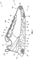
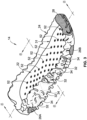
- most of the midsole protrusions 40 will be neighbored on three or four sides thereof by insole protrusions 44, while most of the insole protrusions 44 will be neighbored on three or four sides thereof by midsole protrusions 40, as best seen in FIGS. 5 and 6 .
- each midsole protrusion 40 sits substantially flush against its corresponding insole pocket 46, and each insole protrusion 44 sits substantially flush against its corresponding midsole pocket 42.
- Additional subjacent support for the insole 22 may be provided by a stepped shelf 48 that is integrally formed into the midsole 24 and extends substantially continuously around the portion of the upper midsole surface 25 against which the insole 22 abuts.
- a flange 50 is integrally formed into and projects transversely from the insole 22, extending substantially continuously around the lower insole surface 29. Once properly aligned, the flange 50 of the insole 22 is buttressed on the stepped shelf 48 of the midsole 24.
- a plurality of the midsole protrusions 40 may have distinct heights and widths.
- a large midsole protrusion 40A is shown to be wider and taller than a medium midsole protrusion 40B, which is shown to be taller yet thinner than a small midsole protrusion 40C.
- the heights of the midsole protrusions 40 may progressively increase in a fore-aft direction from the front of the shoe 10 (e.g., forefoot region R FF of FIG.
- the heights of the midsole protrusions 40 may also progressively increase and decrease in a medio-lateral direction from side-to-side of the shoe 10 (e.g., traversing across the lateral and medial segments S LA and S ME from top-to-bottom and bottom-to-top in FIG. 2 ).
- the foregoing description may be similarly applicable to the midsole pockets 42, as represented by the large, medium and small pockets 42A, 42B and 42C, respectively, in FIG. 5 .
- insole protrusions 44 may have distinct heights and widths from one another.
- a large insole protrusion 44A is shown to be taller yet thinner than a medium insole protrusion 44B; medium insole protrusion 44B, in turn, is taller yet thinner than a small insole protrusion 44C.
- the heights of the insole protrusions 44 may progressively increase in a fore-aft direction from the front of the shoe 10 (e.g., forefoot region R FF ) to the middle of the shoe 10 (e.g., midfoot region R MF ), and thereafter progressively decrease from the middle to the rear of the shoe (e.g., midfoot region R MF to hindfoot region R HF ). Further coinciding with the midsole protrusions 40, the heights of the insole protrusions 44 may also progressively increase and decrease in a medio-lateral direction from side-to-side of the shoe 10.
- the foregoing description may be similarly applicable to the insole pockets 46, as represented by the large, medium and small insole pockets 46A, 46B and 46C, respectively, in FIG. 5 .
- a subset of the midsole protrusions 40 each includes an integrally formed nub 52 that projects upwardly from a distal tip thereof.
- These midsole protrusion nubs 52 may be fabricated in a variety of shapes in sizes; as best seen in the lower inset view of FIG. 4 , each nub 52 may be formed with a cylindrical body with a rounded tip at a distal end of the cylindrical body.
- a corresponding subset of the insole pockets 46 each includes a respective through hole 54 that extends through the insole 22 and receives therein a respective one of the midsole protrusion nubs 52. As shown, each nub 52 extends through a corresponding insole pocket hole 54, from the lower insole surface 29 to the upper insole surface 31.
- the nubs are arranged in an engineered pattern that gives a "foot massaging" proprioceptive response for a user of the footwear 10.
- the insole pocket holes 54 may be narrower than the width/diameter of the midsole protrusion nubs 52 such that press fitting the nubs 52 into the holes 54 creates an interference fit coupling between the insole 22 and midsole 24.
Landscapes
- Chemical & Material Sciences (AREA)
- Engineering & Computer Science (AREA)
- Materials Engineering (AREA)
- Health & Medical Sciences (AREA)
- Epidemiology (AREA)
- General Health & Medical Sciences (AREA)
- Public Health (AREA)
- Footwear And Its Accessory, Manufacturing Method And Apparatuses (AREA)
Description
- The present disclosure relates generally to articles of footwear. More specifically, aspects of this disclosure relate to footwear with multilayered sole structures having impact-attenuating midsoles, wear-reducing outsoles, and foot-cushioning insoles.
- Articles of footwear, such as shoes, boots, slippers, sandals, and the like, are generally composed of two primary elements: an upper for securing the footwear to a user's foot; and a sole for providing subjacent support to the foot. Uppers may be fabricated from a variety of materials, including textiles, foams, polymers, natural and synthetic leathers, etc., that are stitched or bonded together to form a shell or harness for securely receiving a foot. Many sandals and slippers have an upper with an open toe or heel construction, with some designs incorporating an upper that is limited to a series of straps extending over the instep and, optionally, around the ankle. Conversely, boot and shoe designs employ a full upper with a closed toe and heel construction that encases the foot. An ankle opening through a rear quarter portion of the footwear provides access to the footwear's interior, facilitating entry and removal of the foot into and from the upper. A shoelace or strap may be utilized to secure the foot within the upper.
- A sole structure is generally attached to the underside of the upper, positioned between the user's foot and the ground. In many articles of footwear, including athletic shoes and boots, the sole structure is a layered construction that generally incorporates a comfort-enhancing insole, an impact-mitigating midsole, and a surface-contacting outsole. The insole, which may be located partially or entirely within the upper, is a thin and compressible member that provides a contact surface for the underside "plantar" region of the user's foot. By comparison, the midsole is mounted underneath the insole, forming a middle layer of the sole structure. In addition to attenuating ground reaction forces, the midsole may help to control foot motion and impart enhanced stability. Secured underneath the midsole is an outsole that forms the ground-contacting portion of the footwear. The outsole is usually fashioned from a durable, waterproof material that includes tread patterns engineered to improve traction.
-
US 2004/103559 A1 describes an insole construction for footwear comprising a base member, an intermediate member formed of a soft foam and having a plurality of substantially uniformly spaced raised cushioning elements on the upper surface thereof, and a flexible cover member surrounding the intermediate member and extending beneath the base member. The intermediate member preferably is formed of a foam such as polyurethane foam. The raised cushioning elements are of a height of approximately 6 millimeters above the upper surface of the intermediate member and are spaced approximately 10-30 millimeters from each other. -
US 10 206 454 B2 - The subject matter of the claimed invention is defined in the independent claims. Specific embodiments are defined in the dependent claims.
- Presented herein are footwear sole structures with foot-cushioning insoles movably mounted onto impact-attenuating midsoles, methods for making and methods for using such sole structures, and articles of footwear fabricated with such sole structures. By way of example, and not limitation, an athletic shoe is disclosed that includes a multilayered sole structure assembly having a compressible polymer foam insole ("core") with an adhesive-free mechanical attachment to a polymer-foam based midsole ("carrier"). A multi-piece, synthetic-rubber outsole may be inlaid at discrete locations along a downward facing, ground-contacting surface of the midsole. In this representative assembly, the insole and midsole are independently molded as distinct, single-piece structures with the insole movably mounted inside the midsole. The midsole and insole nest together via complementary "egg-crate" geometries, with prolate-spheroid-shaped protrusions projecting from an upward facing surface of the midsole and interleaving with prolate-spheroid-shaped protrusions projecting from a downward facing surface of the insole. Distal ends of the prolate-spheroid-shaped protrusions nest flush within complementary pockets recessed into the facing structure of the opposing sole structure element. The respective heights and widths of these protrusions may be distinct from one another, varying in both fore-aft and medio-lateral directions of the footwear.
- Nubs projecting upward from distal tips of the midsole's protrusions extend through complementary holes in the insole. In addition to maintaining proper longitudinal and lateral alignment of the insole within the midsole, these nubs cooperate with the egg-crate interface to allow the insole to "float" on top of the midsole. Moreover, the nubs may have rounded tips and may be arranged in an engineered pattern that gives a "foot massaging" proprioceptive response for the user. The aforementioned mechanical engagement eliminates that need for adhesives and fasteners to join together the insole and midsole. However, the sole structure assembly may be attached to the upper via adhesives and/or fasteners along an inner perimeter of an upwardly extending sidewall of the midsole. For at least some designs, an outer periphery of the insole is sandwiched between the midsole and upper, helping to retain the insert in place while not obstructing the footbed portion of the insole against which the user's foot rests. The midsole foam composition may absorb about 30% or less of compression forces imparted by the user to provide a softer feel with 15-20% more energy return compared to comparable foam sole structures.
- Aspects of this disclosure are directed to multilayered footwear sole structures with foot-cushioning insoles coupled to impact-attenuating midsoles via complementary, intermeshing convoluted surfaces. In an example, a sole structure for an article of footwear includes an insole that is movably mounted - or "floats" - on a subjacent midsole. The midsole is formed, in whole or in part, from a compressible (first) material having an engineered (first) hardness. The midsole has a ground-facing lower surface opposite a foot-facing upper surface. Multiple (first) protrusions project upwardly from the midsole's upper surface, and multiple (first) pockets are recessed into the midsole's upper surface and interleaved with the midsole's protrusions. The insole is formed, in whole or in part, from a compressible (second) material having an engineered (second) hardness that is less than the hardness of the midsole. The insole has opposing upper and lower surfaces with multiple (second) protrusions projecting downwardly from the insole's lower surface and interleaved with the midsole's protrusions. Multiple (second) pockets are recessed into the insole's lower surface and interleaved with the insole's protrusions. Each midsole protrusion nests within one of the insole's pockets, while each insole protrusion nests within one of the midsole's pockets.
- Other aspects of this disclosure are directed to footwear fabricated with any of the disclosed multilayered sole structure assemblies. As an example, an article of footwear includes an upper that receives and attaches to a foot of a user, and a sole structure that is attached to the upper to support thereon the user's foot. The sole structure includes a midsole, an insole movably mounted on the midsole, and an optional outsole rigidly mounted along the underside of the midsole. The midsole, which is formed with a compressible polymeric material, includes a ground-facing lower midsole surface opposite an upper midsole surface. Multiple protrusions project from the upper midsole surface, and multiple pockets are recessed into the upper midsole surface and interleaved with the first protrusions. The insole is formed with a distinct compressible polymeric material having a hardness that is less than the hardness of the midsole material. The insole has an upper insole surface opposite a lower insole surface, multiple protrusions projecting from the lower insole surface and interleaved with the midsole's protrusions, and multiple pockets recessed into the lower insole surface and interleaved with the insole's protrusions. Each midsole protrusion nests within a respective one of the insole's pockets, whereas each insole protrusion nests within a respective one of the midsole's pockets.
- Additional aspects of this disclosure are directed to methods for manufacturing and methods for using any of the disclosed footwear and/or sole structures. In an example, a method is presented for manufacturing a sole structure for an article of footwear. This representative method includes, in any order and in any combination with any of the above or below disclosed features and options: forming, using a first material having a first hardness, a midsole having opposing upper and lower midsole surfaces, multiple first protrusions projecting from the upper midsole surface, and multiple first pockets recessed into the upper midsole surface and interleaved with the first protrusions; forming, using a second material having a second hardness less than the first hardness, an insole having opposing upper and lower insole surfaces, multiple second protrusions projecting from the lower insole surface and interleaved with the first protrusions, and multiple second pockets recessed into the lower insole surface and interleaved with the second protrusions; and mounting the insole onto the midsole such that each of the first protrusions is nested within a respective one of the second pockets, and each of the second protrusions is nested within a respective one of the first pockets.
- For any of the disclosed sole structures, footwear, and manufacturing methods, each midsole protrusion may sit substantially flush against its respective insole pocket, whereas each insole protrusion may sits substantially flush against its respective midsole pocket. While innumerable shapes, sizes and orientations are envisioned, each protrusion may have a prolate-spheroid shape with a rectangular base. Moreover, a plurality of the midsole protrusions may each have a distinct height, and a plurality of the insole protrusions may each have a distinct height. In the same vein, a plurality of the midsole protrusions may each have a distinct width, and a plurality of the insole protrusions may each have a distinct width. Optionally, the midsole's protrusions and pockets may be arranged in a series of medio-lateral rows that extend transversely across the midsole. Likewise, the insole protrusions and pockets may be arranged in a series of medio-lateral rows that extend transversely across the insole.
- For any of the disclosed sole structures, footwear, and manufacturing methods, a subset of the midsole's protrusions each include a respective nub that projects upwardly from a distal tip thereof. A corresponding subset of the insole's pockets each include a respective hole that receives therein one of these nubs. In at least some configurations, the holes in the insole have a first width, and the nubs of the midsole protrusions have a second width greater than the first width. In so doing, press fitting the nubs into the holes creates an interference fit coupling between the insole and midsole. As a further option each nub may extend all the way through its respective hole from the lower insole surface to the upper insole surface. While innumerable shapes, sizes and orientations are envisioned, each nub may have a cylindrical body with a rounded tip that protrudes from the insole's upper surface.
- For any of the disclosed sole structures, footwear, and manufacturing methods, the midsole may be fabricated with a stepped shelf that extends substantially continuously around and circumscribes the midsole's upper surface. The insole may be fabricated with a flange that extends substantially continuously around and circumscribes the insole's lower surface. When the insole is properly mounted on the midsole, the insole's flange is buttressed on the midsole's stepped shelf. While not per se required, any of the disclosed sole structure assemblies may include an outsole that is formed, in whole or in part, from a third material that is harder than the insole and midsole materials. The outsole may be mounted to the ground-facing lower surface of the midsole. The outsole may be molded as a bipartite structure from a synthetic rubber. Optionally, the midsole may be molded as a distinct, single-piece structure from one polymer foam material, and the insole may be molded as a distinct, single-piece structure from another polymer foam material. An optional toe shield formed from a wear-resistant polymeric material may be mounted on a front end of the midsole. It is envisioned that any suitable manufacturing technique may be used to fabricate a disclosed sole structure assembly or a constituent part thereof, including injection, compression and/or multi-shot molding.
- The above summary is not intended to represent every embodiment or every aspect of the present disclosure. Rather, the foregoing summary merely provides an exemplification of some of the novel concepts and features set forth herein. The above features and advantages, and other features and attendant advantages of this disclosure, will be readily apparent from the following detailed description of illustrated examples and representative modes for carrying out the present disclosure when taken in connection with the accompanying drawings and the appended claims. Moreover, this disclosure expressly includes any and all combinations and subcombinations of the elements and features presented above and below.
-
FIG. 1 is a lateral, side-view illustration of a representative article of footwear with a multilayered sole structure assembly in accordance with aspects of the present disclosure. -
FIG. 2 is a bottom-view illustration of the representative article of footwear and multilayered sole structure assembly ofFIG. 1 . -
FIG. 3 is an elevated, perspective-view illustration of the sole structure assembly ofFIG. 2 with the footwear upper removed. -
FIG. 4 is an exploded, perspective-view illustration of the sole structure assembly ofFIG. 3 with the insole partially inverted to show the insole's lower surface. -
FIG. 5 is a longitudinal cross-sectional illustration of the representative insole and midsole of the sole structure assembly ofFIG. 1 taken along line 5-5 ofFIG. 3 . -
FIG. 6 is a transverse cross-sectional illustration of the representative insole and midsole of the sole structure assembly ofFIG. 1 taken along line 6-6 ofFIG. 3 . - The present disclosure is amenable to various modifications and alternative forms, and some representative embodiments are shown by way of example in the drawings and will be described in detail herein. It should be understood, however, that novel aspects of this disclosure are not limited to the particular forms illustrated in the above-enumerated drawings. Rather, the disclosure is to cover all modifications, equivalents, combinations, subcombinations, permutations, groupings, and alternatives falling within the scope of this disclosure as encompassed by the appended claims.
- This disclosure is susceptible of embodiment in many different forms. Representative examples of the disclosure are shown in the drawings and will be described in detail herein with the understanding that these representative examples are provided as an exemplification of the disclosed principles, not limitations of the broad aspects of the disclosure. To that extent, elements and limitations that are described in the Abstract, Technical Field, Background, Summary, and Detailed Description sections, but not explicitly set forth in the claims, should not be incorporated into the claims, singly or collectively, by implication, inference or otherwise.
- For purposes of the present detailed description, unless specifically disclaimed: the singular includes the plural and vice versa; the words "and" and "or" shall be both conjunctive and disjunctive; the words "any" and "all" shall both mean "any and all"; and the words "including," "comprising," "having," "containing," and the like shall each mean "including without limitation." Moreover, words of approximation, such as "about," "almost," "substantially," "approximately," and the like, may be used herein in the sense of "at, near, or nearly at," or "within 0-5% of," or "within acceptable manufacturing tolerances," or any logical combination thereof, for example. Lastly, directional adjectives and adverbs, such as fore, aft, medial, lateral, proximal, distal, vertical, horizontal, front, back, left, right, etc., may be with respect to an article of footwear when worn on a user's foot and operatively oriented with a designated ground-engaging portion of the sole structure seated on a flat surface, for example.
- Referring now to the drawings, wherein like reference numbers refer to like features throughout the several views, there is shown in
FIG. 1 a representative article of footwear, which is designated generally at 10 and portrayed herein for purposes of discussion as an athletic shoe or "sneaker." The illustrated article of footwear 10 - also referred to herein as "footwear" or "shoe" for brevity - is an exemplary application with which novel aspects and features of this disclosure may be practiced. In the same vein, implementation of the present concepts for a trilayer, polymer sole structure assembly should also be appreciated as a representative implementation of the disclosed concepts. It will therefore be understood that aspects and features of this disclosure may be utilized for sole structures with alternative chemical makeups and/or sole structures with different layer compositions, and may be incorporated into any logically relevant type of footwear. As used herein, the terms "shoe" and "footwear," including permutations thereof, may be used interchangeably and synonymously to reference any suitable type of garment worn on a human foot. Lastly, features presented in the drawings are not necessarily to scale and are provided purely for instructional purposes. Thus, the specific and relative dimensions shown in the drawings are not to be construed as limiting. - The representative article of
footwear 10 is generally depicted inFIGS. 1 and2 as a bipartite construction that is primarily composed of a foot-receiving upper 12 mounted on top of a subjacentsole structure 14. For ease of reference,footwear 10 may be divided into three anatomical regions: a forefoot region RFF, a midfoot region RMF, and a hindfoot (heel) region RHF, as shown inFIG. 2 .Footwear 10 may also be divided along a vertical plane into a lateral segment SLA - a distal half of theshoe 10 farthest from the sagittal plane of the human body - and a medial segment SME - a proximal half of theshoe 10 closest to the sagittal plane of the human body. In accordance with recognized anatomical classification, the forefoot region RFF is located at the front of thefootwear 10 and generally corresponds with the phalanges (toes), metatarsals, and any interconnecting joints thereof. Interposed between the forefoot and hindfoot regions RFF and RHF is the midfoot region RMF, which generally corresponds with the cuneiform, navicular and cuboid bones (i.e., the arch area of the foot). Hindfoot region RHF, in contrast, is located at the rear of thefootwear 10 and generally corresponds with the talus (ankle) and calcaneus (heel) bones. Both lateral and medial segments SLA and SME of thefootwear 10 extend through all three anatomical regions RFF, RMF, RHF, and each corresponds to a respective transverse side of thefootwear 10. While only asingle shoe 10 for a right foot of a user is shown inFIGS. 1 and2 , a mirrored, substantially identical counterpart for a left foot of a user may be provided. Recognizably, the shape, size, material composition, and method of manufacture of theshoe 10 may be varied, singly or collectively, to accommodate practically any conventional or nonconventional footwear application. - With reference again to
FIG. 1 , the upper 12 is depicted as having a shell-like closed toe and heel configuration for encasing a human foot.Upper 12 ofFIG. 1 is generally defined by three adjoining sections, namely atoe box 12A, avamp 12B and arear quarter 12C. Thetoe box 12A is shown as a rounded forward tip of the upper 12 that extends from distal to proximal phalanges to cover and protect the user's toes. By comparison, thevamp 12B is an arched midsection of the upper 12 that is located aft of thetoe box 12A and extends from the metatarsals to the cuboid. As shown, thevamp 12B also provides a series of lace eyelets 16 and ashoe tongue 18. Positioned aft of thevamp 12B is arear quarter 12C that extends from the transverse tarsal joint to wrap around the calcaneus bone, and includes the rear end and rear sides of the upper 12. While portrayed in the drawings as comprising three primary segments, the upper 12 may be fabricated as a single-piece construction or may be composed of any number of segments, including atoe shield 28, heel cap, ankle cuff, interior liner, etc. For sandal and slipper applications, the upper 12 may take on an open toe or open heel configuration, or may be replaced with a single strap or multiple interconnected straps. - The upper 12 portion of the
footwear 10 may be fabricated from any one or combination of a variety of materials, such as textiles, engineered foams, polymers, natural and synthetic leathers, etc. Individual segments of the upper 12, once cut to shape and size, may be stitched, adhesively bonded, fastened, welded or otherwise joined together to form an interior void for comfortably receiving a foot. The individual material elements of the upper 12 may be selected and located with respect to thefootwear 10 in order to impart desired properties of durability, air-permeability, wear-resistance, flexibility, appearance, and comfort, for example. Anankle opening 15 in therear quarter 12C of the upper 12 provides access to the interior of theshoe 10. Ashoelace 20, strap, buckle, or other commercially available mechanism may be utilized to modify the girth of the upper 12 to more securely retain the foot within the interior of theshoe 10 as well as to facilitate entry and removal of the foot from the upper 12.Shoelace 20 may be threaded through a series ofeyelets 16 in or attached to the upper 12; thetongue 18 may extend between thelace 20 and the interior void of the upper 12. -
Sole structure 14 is rigidly secured to the upper 12 such that thesole structure 14 extends between the upper 12 and a support surface upon which a user stands. In effect, thesole structure 14 functions as an intermediate support platform that separates and protects the user's foot from the ground. In addition to attenuating ground reaction forces and providing cushioning for the foot,sole structure 14 ofFIGS. 1 and2 may provide traction, impart stability, and help to limit various foot motions, such as inadvertent foot inversion and eversion. It is envisioned that thesole structure 14 may be attached to the upper 12 in any presently available or hereinafter developed suitable means. For at least some applications, the upper 12 may be coupled directly to themidsole 24 and, thus, lack a direct coupling to either theinsole 22 or theoutsole 26. By way of non-limiting example, the upper 12 may be adhesively attached to only an inside periphery of amidsole sidewall 21, e.g., secured with a 10mm bonding allowance via priming, cementing, and pressing. - In accordance with the illustrated example, the
sole structure 14 is fabricated as a sandwich structure with a foot-contacting insole 22 (FIG. 3 ), anintermediate midsole 24, and abottom-most outsole 26. Alternative sole structure configurations may be fabricated with greater or fewer than three layers.Insole 22 is shown located within an interior void of thefootwear 10, operatively located at a lower portion of the upper 12, such that theinsole 22 abuts a plantar surface of the foot. Underneath theinsole 22 is amidsole 24 that incorporates one or more materials or embedded elements that enhance the comfort, performance, and/or ground-reaction-force attenuation properties offootwear 10. These elements and materials may include, individually or in any combination, a polymer foam material, such as polyurethane or ethyl vinyl acetate (EVA), filler materials, moderators, air-filled bladders, plates, lasting elements, or motion control members.Outsole 26 is located underneath themidsole 24, defining only some or all of the bottom-most, ground-engaging portion of thefootwear 10. Theoutsole 26 may be formed from a natural or synthetic rubber material that provides a durable and wear-resistant surface for contacting the ground. In addition, theoutsole 26 may be contoured and textured to enhance the traction (i.e., friction) properties betweenfootwear 10 and the underlying support surface. - With collective reference to
FIGS. 1-3 , thesole structure 14 is fabricated with the foot-cushioninginsole 22 movably attached to the impact-force-attenuatingmidsole 24, which is formed with a pressure-mapped, outboard-facing topography and inlaid with the wear-mitigating,multipart outsole 26. In accord with the illustrated example, themidsole 24 is formed, in whole or in part, from a compressible (first) material having a relatively moderate (first) hardness, e.g., as measured according to a suitable one of the Shore Hardness Scales or other universally-recognized methodology for gauging material rigidity. Thedetachable insole 22, which floats on a top surface of themidsole 24, is formed, in whole or in part, from a distinct, compressible (second) material having a relatively low (second) hardness that is measurably less than that of themidsole 24. In this regard, thesole structure 14 may be characterized by a lack of an adhesive bond between theinsole 22 and the midsole 24 (or any other structure, for that matter). By comparison, first andsecond outsole segments midsole 24, e.g., priming, cement adhesive, stock-fitting and pressing, and is formed, in whole or in part, from an elastic (third) material with a relatively high (third) hardness that is greater than the hardnesses of the midsole's and insole's materials. - It may be desirable, for at least some applications, that the Shore A hardness of the outsole material be larger than the Shore A hardness of the midsole material, e.g., by at least about 20% and larger than the Shore A hardness of the insole material by at least about 50%. As a non-limiting example, the midsole material may include a polymer foam material, such as thermoplastic polyurethane (TPU) foam, Phylon, Phylite, or EVA, having a material hardness in the range of about 40 to about 60 Shore A (e.g., about 65 to about 80 Asker C). Conversely, the outsole material may include an elastic polymer material, such as polyvinylchloride (PVC), hard-compound polyurethane (PU), or a polycaprolactone (PCL) or polyester-based TPU, having a material hardness of about 75 to about 90 Shore A. The insole, on the other hand, may include a softer polymer foam material, such as a lightweight polyurethane foam, having a material hardness of about 20 to about 35 Shore A. In a specific implementation, the
midsole 24 is formed via compression molding as a one-piece, unitary structure from a polymer foam, such as a proprietary REACT® TPU elastomer, having a density of about 0.15 to about 0.25 g/cm3. In this example, theoutsole 26 is formed via blowing and cutting as a bipartite structure from a synthetic rubber, such as ethylene propylene rubber (EPR), styrene isoprene styrene (SIS) copolymer rubber, styrene butadiene rubber.Insole 22 may be formed via compression molding as a one-piece, unitary structure from a polymer foam, such as a PU foam having a specific gravity of about 0.15-0.25 and a density of less than about 0.25 g/cm3. - To enhance underfoot cushioning during use of the
footwear 10, while concomitantly enhancing attenuation or ground reaction forces, increasing energy return, and minimizing gross shoe weight, the midsole's outboard topography is provided with an engineered pattern of projections and cavities, the shapes, sizes, locations, and orientations of which are designed to coincide with pressure zones identified through sensor-generated pressure map data. A normative population of individuals were provided with athletic shoes retrofit with a distributed array of sensors in the sock liner. These individuals underwent pressure-map testing throughout a full day of use to chart the points along the plantar region of the foot that experiences the largest and smallest magnitudes of pressure from walking, running, frequent lateral maneuvers, and the like. The aforementioned topology parameters of the midsole were then derived through algebraic tiles applied to the resultant pressure map data to create a patterned midsole that allocates polymer foam density according to pressure magnitude distribution. - The largest concentrations of
midsole 24 andoutsole 26 mass may be allocated at regions of thesole structure 14 that have been determined to coincide with increased-magnitude pressure zones of the plantar region. At the same time, respective concentrations ofmidsole 24 andoutsole 26 mass may be minimized or completely eliminated at regions of thesole structure 14 that coincide with decreased-magnitude pressure zones of the plantar region. Outwardly facing surfaces of themidsole 24, including rearward and lateral-facing surface segments of amidsole sidewall 21 and ground-facing surface segments of amidsole base 23, are formed with an assortment of recessedcavities 32 interleaved with an assortment of outwardly protrudingprojections 34. Each of thecavities 32 is delineated by coterminous, ground-contactingprojections 34 of varying shapes, sizes and orientations. Empty cavities 32 - those not occupied by asegment sole structure 14 that coincide with reduced-magnitude pressure zones of the user's plantar region. To do so, however, may require eachcavity 32 have a distinct shape, depth and/or width from everyother cavity 32. Conversely, filled cavities 32 - those occupied by a section of the outsole 26 - are mapped to predetermined sections ofsole structure 14 that coincide with increased-magnitude pressure zones of the plantar region. As a result of the distinctly shapedcavities 32, eachprojection 34 may have a distinct shape, height and/or orientation from everyother projection 34. According to the illustrated example, theoutsole 26 fills multiple sections of themidsole channels 34; in so doing, segments of theoutsole 26 will share the shape and dimensions of the corresponding midsole channel(s) 34 in which they occupy. - By way of contrast to the
outsole 26, which is rigidly mounted on and, thus, fixedly attached to themidsole 24, theinsole 22 is movably mounted on and detachable from themidsole 24. That is not to say that theinsole 22 is loosely laid on top of themidsole 24; rather, an adhesive-free mechanical attachment couples theinsole 22 to themidsole 24 while allowing for a predetermined amount of fore-aft and medio-lateral play between the two elements. As best seen in the exploded perspective-view illustration ofFIG. 4 , an array of midsole protrusions 40 (also referred to herein as "first protrusions") projects upwardly from a foot-facingupper surface 25 of themidsole 24, which is opposite a ground-facing lower midsole surface 27 (FIG. 1 ). While it is envisioned that theprotrusions 40 may take on assorted combinations of shapes, sizes, and orientations, eachprotrusion 40 ofFIG. 4 has a prolate-spheroid shapedbody 41 with a rectangular base 43 (see lower inset view ofFIG. 4 ). A prolate-spheroid shape may provide added underfoot comfort, e.g., as compared to blunt ended or sharp pointed protrusions. The midsole protrusions 40 may be approximately 1.0-4.0 mm high, as measured from thebase 43, and may project generally perpendicular from theupper midsole surface 25. It may be desirable, for at least some applications, that themidsole 24 includes at least about fiftyprotrusions 40 or, for at least some applications, at least about seventyprotrusions 40 depending, for example, on the shoe size of thefootwear 10. - Interleaved with the midsole's
protrusions 40 is an array of midsole pockets 42 (also referred to herein as "first pockets") recessed into theupper midsole surface 25. Like themidsole protrusions 40, thepockets 42 may take on assorted combinations of shapes, sizes, and orientations; pockets 42 ofFIG. 4 are portrayed as having a prolate-spheroid shapedcavity 45 with arectangular window 47. These midsole pockets 42 may be approximately 1.0-3.0 mm deep, as measured from thewindow 47. In accord with the illustrated architecture, each of thepockets 42 may neighbor and be delineated by multiplecoterminous protrusions 40. As shown, themidsole protrusions 40 andpockets 42 are arranged in a series of medio-lateral rows - represented herein by first, second and third rectilinear rows R1-R3 ofFIG. 4 - extending transversely across themidsole 24 and, thus thesole structure 14. Optionally, themidsole protrusions 40 and pockets 42 may also be arranged in a series of fore-aft columns - represented herein by first, second and third curvilinear columns C1-C3 ofFIG. 4 - extending longitudinally across themidsole 24 and, thus thesole structure 14. It may be desirable, for at least some applications, that themidsole 24 includes at least about fiftypockets 42 or, for at least some applications, at least about seventypockets 42. Theprotrusions 40 and pockets 42 may cooperatively cover at least about 60-70% of the midsole's 24upper surface 25. - To provide a complementary interface for mechanically attaching to the
midsole 24, theinsole 22 has a ground-facinglower surface 29, opposite a foot-facing upper insole surface 31 (FIG. 3 ), with multiple insole protrusions 44 (also referred to herein as "second protrusions") projecting downwardly therefrom. Similar to themidsole protrusions 40,insole protrusions 44 may take on various combinations of shapes, sizes, and orientations; eachprotrusion 44, for example, has a prolate-spheroid shapedbody 49 with a rectangular base 51 (see upper inset view ofFIG. 4 ). The insole protrusions 44 may be approximately 1.0-3.0 mm high, as measured from thebase 51, and may project generally perpendicular from thelower insole surface 29. It may be desirable, for at least some applications, that theinsole 24 includes at least about fiftyprotrusions 44 or, for at least some applications, at least about seventyprotrusions 44, e.g., to coincide with the number of midsole pockets 42. - Multiple insole pockets 46 (also referred to herein as "second pockets") are recessed into the
lower insole surface 29, interleaved with theinsole protrusions 44. Similar to the midsole pockets 42, the insole pockets 46 may take on assorted combinations of shapes, sizes, and orientations; pockets 46 ofFIG. 4 are portrayed as having a prolate-spheroid shapedcavity 53 with arectangular window 55. Generally speaking, the inner periphery of each midsole/insole pocket midsole protrusion window 47, to match the heights of themidsole protrusions 40. With this arrangement, eachinsole pocket 46 may neighbor and be delineated by multiplecoterminous insole protrusions 44. It may be desirable, for at least some applications, that theinsole 24 includes at least about fiftypockets 46 or, for at least some applications, at least about seventypockets 46, e.g., to coincide with the number ofmidsole protrusions 40. Theprotrusions 44 and pockets 46 may cooperatively cover at least about 80-90% of the insole's 22lower surface 29. - As shown, the
insole protrusions 44 andpockets 46 are arranged in a series of medio-lateral rows - represented herein by fourth, fifth and sixth rectilinear rows R4-R6 ofFIG. 4 - extending transversely across theinsole 22 and, thus, thesole structure 14. The illustrated medio-lateral rows of the insole 22 (e.g., rows R4-R6) are parallel to one another and, for at least the illustrated embodiment, parallel with the medio-lateral rows of the midsole 24 (e.g., rows R1-R3). As a further option, theinsole protrusions 44 and pockets 46 may also be arranged in a series of fore-aft columns - represented herein by fourth, fifth and sixth curvilinear columns C4-C6 ofFIG. 4 - that extend longitudinally across theinsole 22. Each fore-aft insole column (e.g., columns C4-C6) may be aligned with a respective one of the fore-aft midsole columns (e.g., columns C1-C3). - When properly mated, the
insole 22 andmidsole 24 intermesh via complementary "egg-crate" geometries with themidsole protrusions 40 inserted alternatively between theinsole protrusions 44. Concomitantly, eachmidsole protrusion 40 seats inside and is surrounded by arespective insole pocket 46, while eachinsole protrusion 44 seats inside and is surrounded by arespective midsole pocket 42. With this configuration, most of themidsole protrusions 40 will be neighbored on three or four sides thereof byinsole protrusions 44, while most of theinsole protrusions 44 will be neighbored on three or four sides thereof bymidsole protrusions 40, as best seen inFIGS. 5 and6 . According to the illustrated example, eachmidsole protrusion 40 sits substantially flush against its correspondinginsole pocket 46, and eachinsole protrusion 44 sits substantially flush against its correspondingmidsole pocket 42. Additional subjacent support for theinsole 22 may be provided by a steppedshelf 48 that is integrally formed into themidsole 24 and extends substantially continuously around the portion of theupper midsole surface 25 against which theinsole 22 abuts. Aflange 50 is integrally formed into and projects transversely from theinsole 22, extending substantially continuously around thelower insole surface 29. Once properly aligned, theflange 50 of theinsole 22 is buttressed on the steppedshelf 48 of themidsole 24. - With reference again to
FIGS. 5 and6 , a plurality of themidsole protrusions 40 may have distinct heights and widths. InFIG. 5 , for example, alarge midsole protrusion 40A is shown to be wider and taller than amedium midsole protrusion 40B, which is shown to be taller yet thinner than asmall midsole protrusion 40C. The heights of themidsole protrusions 40 may progressively increase in a fore-aft direction from the front of the shoe 10 (e.g., forefoot region RFF ofFIG. 2 ) to the middle of the shoe 10 (e.g., midfoot region RMF), and thereafter progressively decrease from the middle to the rear of the shoe (e.g., midfoot to hindfoot region RMF, RHF). The heights of themidsole protrusions 40 may also progressively increase and decrease in a medio-lateral direction from side-to-side of the shoe 10 (e.g., traversing across the lateral and medial segments SLA and SME from top-to-bottom and bottom-to-top inFIG. 2 ). The foregoing description may be similarly applicable to the midsole pockets 42, as represented by the large, medium andsmall pockets FIG. 5 . - Similar to the
midsole protrusions 40, many of theinsole protrusions 44 may have distinct heights and widths from one another. InFIG. 5 , for example, alarge insole protrusion 44A is shown to be taller yet thinner than amedium insole protrusion 44B;medium insole protrusion 44B, in turn, is taller yet thinner than asmall insole protrusion 44C. In the same vein, the heights of theinsole protrusions 44 may progressively increase in a fore-aft direction from the front of the shoe 10 (e.g., forefoot region RFF) to the middle of the shoe 10 (e.g., midfoot region RMF), and thereafter progressively decrease from the middle to the rear of the shoe (e.g., midfoot region RMF to hindfoot region RHF). Further coinciding with themidsole protrusions 40, the heights of theinsole protrusions 44 may also progressively increase and decrease in a medio-lateral direction from side-to-side of theshoe 10. The foregoing description may be similarly applicable to the insole pockets 46, as represented by the large, medium and small insole pockets 46A, 46B and 46C, respectively, inFIG. 5 . - A subset of the
midsole protrusions 40 each includes an integrally formednub 52 that projects upwardly from a distal tip thereof. These midsole protrusionnubs 52 may be fabricated in a variety of shapes in sizes; as best seen in the lower inset view ofFIG. 4 , each nub 52 may be formed with a cylindrical body with a rounded tip at a distal end of the cylindrical body. Likewise, a corresponding subset of the insole pockets 46 each includes a respective throughhole 54 that extends through theinsole 22 and receives therein a respective one of themidsole protrusion nubs 52. As shown, each nub 52 extends through a correspondinginsole pocket hole 54, from thelower insole surface 29 to theupper insole surface 31. The nubs are arranged in an engineered pattern that gives a "foot massaging" proprioceptive response for a user of thefootwear 10. While not per se required, the insole pocket holes 54 may be narrower than the width/diameter of themidsole protrusion nubs 52 such that press fitting thenubs 52 into theholes 54 creates an interference fit coupling between theinsole 22 andmidsole 24.
Claims (14)
- A sole structure (14) for an article of footwear (10), the sole structure (14) comprising:a midsole (24) formed with a first compressible material having a first hardness, the midsole (24) having a ground-facing lower midsole surface (27) opposite an upper midsole surface (25), multiple first protrusions (40) projecting from the upper midsole surface (25), and multiple first pockets (42) recessed into the upper midsole surface (25) and interleaved with the first protrusions (40); andan insole (22) movably mounted on the midsole (24) and formed with a second compressible material having a second hardness less than the first hardness, the insole (22) having an upper insole surface (31) opposite a lower insole surface (29), multiple second protrusions (44) projecting from the lower insole surface (29) and interleaved with the first protrusions (40), and multiple second pockets (46) recessed into the lower insole surface (29) and interleaved with the second protrusions (44),wherein each of the first protrusions (40) nests within a respective one of the second pockets (46), and each of the second protrusions (44) nests within a respective one of the first pockets (42), andcharacterised in thata subset of the first protrusions (40) each includes a respective nub (52) projecting from a distal tip thereof, and a subset of the second pockets (46) each includes a respective hole (54) receiving therein a respective one of the nubs (52).
- The sole structure (14) of claim 1, wherein each of the first protrusions (40) sits substantially flush against the respective one of the second pockets (46), and wherein each of the second protrusions (44) sits substantially flush against the respective one of the first pockets (42).
- The sole structure (14) of claim 1 or claim 2, wherein each of the first and second protrusions (44) has a prolate-spheroid shape with a rectangular base.
- The sole structure (14) of any of claims 1 to 3, wherein a first plurality of the first protrusions (40) each has a distinct height, and wherein a second plurality of the second protrusions (44) each has a distinct height.
- The sole structure (14) of any of claims 1 to 4, wherein a first plurality of the first protrusions (40) each has a distinct width, and wherein a second plurality of the second protrusions (44) each has a distinct width.
- The sole structure (14) of any of claims 1 to 5, wherein the first protrusions (40) and first pockets (42) are arranged in a first plurality of medio-lateral rows (R1, R2, R3) extending transversely across the midsole (24), and the second protrusions (44) and second pockets (46) are arranged in a second plurality of medio-lateral rows (R4, R5, R6) extending transversely across the insole (22).
- The sole structure (14) of any of claims 1 to 6, wherein the holes (54) in the insole (22) have a first width, and the nubs (52) of the first protrusions (40) have a second width greater than the first width such that press fitting the nubs (52) into the holes (54) creates an interference fit coupling between the insole (22) and midsole (24).
- The sole structure (14) of any of claims 1 to 7, wherein each of the nubs (52) extends through the respective hole (54) from the lower insole surface (29) to the upper insole surface (31).
- The sole structure (14) of any of claims 1 to 8, wherein each of the nubs (52) has a respective cylindrical body with a rounded tip at a distal end of the cylindrical body.
- The sole structure (14) of any of claims 1 to 9, wherein the midsole (24) includes a stepped shelf (48) extending substantially continuously around the upper midsole surface (25), and the insole (22) includes a flange (50) extending substantially continuously around the lower insole surface (29), wherein the flange (50) of the insole (22) is buttressed on the stepped shelf (48) of the midsole (24).
- The sole structure (14) of claim any of claims 1 to 10, further comprising an outsole (26) formed with a third material having a third hardness greater than the first and second hardnesses, the outsole (26) being mounted to the ground-facing lower midsole surface (27).
- The sole structure (14) of claim 11, wherein the outsole (26) is molded as a bipartite structure from a synthetic rubber.
- The sole structure (14) of any of claims 1 to 12, wherein the midsole (24) is molded as a first single-piece structure from a first polymer foam, and wherein the insole (22) is molded as a second single-piece structure from a second polymer foam distinct from the first polymer foam.
- The sole structure (14) of any of claims 1 to 13, wherein the sole structure (14) is characterized by a lack of an adhesive bond between the insole (22) and the midsole (24).
Applications Claiming Priority (2)
| Application Number | Priority Date | Filing Date | Title |
|---|---|---|---|
| US16/288,871 US10874169B2 (en) | 2019-02-28 | 2019-02-28 | Footwear and sole structure assemblies with adhesive-free mechanical attachments between insoles and midsoles |
| PCT/US2019/062786 WO2020176152A1 (en) | 2019-02-28 | 2019-11-22 | Footwear and sole structure assemblies with adhesive-free mechanical attachments between insoles and midsoles |
Publications (2)
| Publication Number | Publication Date |
|---|---|
| EP3930526A1 EP3930526A1 (en) | 2022-01-05 |
| EP3930526B1 true EP3930526B1 (en) | 2024-06-19 |
Family
ID=68944399
Family Applications (1)
| Application Number | Title | Priority Date | Filing Date |
|---|---|---|---|
| EP19823841.2A Active EP3930526B1 (en) | 2019-02-28 | 2019-11-22 | Footwear and sole structure assemblies with adhesive-free mechanical attachments between insoles and midsoles |
Country Status (4)
| Country | Link |
|---|---|
| US (3) | US10874169B2 (en) |
| EP (1) | EP3930526B1 (en) |
| CN (1) | CN113423298B (en) |
| WO (1) | WO2020176152A1 (en) |
Cited By (1)
| Publication number | Priority date | Publication date | Assignee | Title |
|---|---|---|---|---|
| EP4218482A4 (en) * | 2020-09-23 | 2024-10-23 | Ho Dong Sung | SHOES |
Families Citing this family (40)
| Publication number | Priority date | Publication date | Assignee | Title |
|---|---|---|---|---|
| US10149513B1 (en) * | 2018-01-31 | 2018-12-11 | Nike, Inc. | Sole structure for article of footwear |
| US11452334B2 (en) | 2018-01-31 | 2022-09-27 | Nike, Inc. | Airbag for article of footwear |
| US10524540B1 (en) | 2018-07-17 | 2020-01-07 | Nike, Inc. | Airbag for article of footwear |
| US11026476B2 (en) | 2018-07-17 | 2021-06-08 | Nike, Inc. | Airbag for article of footwear |
| US10874169B2 (en) * | 2019-02-28 | 2020-12-29 | Nike, Inc. | Footwear and sole structure assemblies with adhesive-free mechanical attachments between insoles and midsoles |
| USD906654S1 (en) * | 2019-05-31 | 2021-01-05 | Fuerst Group, Inc. | Footwear bottom |
| USD884326S1 (en) * | 2019-08-16 | 2020-05-19 | Nike, Inc. | Shoe |
| US12082651B2 (en) * | 2019-09-20 | 2024-09-10 | R. G. Barry Corporation | Footwear article including cushion management system |
| WO2021066943A1 (en) * | 2019-10-04 | 2021-04-08 | Nike Innovate C.V. | Footwear midsole and method of manufacturing with embroidery machine |
| USD923303S1 (en) * | 2020-01-10 | 2021-06-29 | Nike, Inc. | Shoe |
| USD923305S1 (en) * | 2020-01-10 | 2021-06-29 | Nike, Inc. | Shoe |
| USD923304S1 (en) * | 2020-01-10 | 2021-06-29 | Nike, Inc. | Shoe |
| USD923298S1 (en) * | 2020-01-10 | 2021-06-29 | Nike, Inc. | Shoe |
| USD909729S1 (en) * | 2020-02-11 | 2021-02-09 | Nike, Inc. | Shoe |
| USD909724S1 (en) * | 2020-02-11 | 2021-02-09 | Nike, Inc. | Shoe |
| WO2021211247A1 (en) * | 2020-04-13 | 2021-10-21 | Nike Innovate C.V. | Footwear and sole structure assemblies with split midsoles having peripheral walls for lateral stability |
| USD945758S1 (en) * | 2020-06-25 | 2022-03-15 | Nike, Inc. | Shoe |
| USD945759S1 (en) * | 2020-06-25 | 2022-03-15 | Nike, Inc. | Shoe |
| USD945755S1 (en) * | 2020-06-25 | 2022-03-15 | Nike, Inc. | Shoe |
| EP3928970A1 (en) * | 2020-06-26 | 2021-12-29 | Ecco Sko A/S | An article of footwear |
| USD915754S1 (en) * | 2020-07-10 | 2021-04-13 | Nike, Inc. | Shoe |
| CN121621634A (en) * | 2020-07-13 | 2026-03-10 | 耐克创新有限合伙公司 | Sole structure with midsole protrusions for forward momentum and an arcuate profile |
| USD935754S1 (en) * | 2020-10-27 | 2021-11-16 | Nike, Inc. | Shoe |
| USD935752S1 (en) * | 2020-10-27 | 2021-11-16 | Nike, Inc. | Shoe |
| USD935755S1 (en) * | 2020-10-27 | 2021-11-16 | Nike, Inc. | Shoe |
| USD933945S1 (en) * | 2020-10-27 | 2021-10-26 | Nike, Inc. | Shoe |
| JP7538828B2 (en) * | 2021-03-16 | 2024-08-22 | プーマ エス イー | Method for producing a part of a footwear article from a form - Patents.com |
| USD946874S1 (en) * | 2021-05-17 | 2022-03-29 | Nike, Inc. | Shoe |
| USD956401S1 (en) * | 2021-06-17 | 2022-07-05 | Nike, Inc. | Shoe |
| USD949530S1 (en) * | 2021-06-17 | 2022-04-26 | Nike, Inc. | Shoe |
| USD1029475S1 (en) | 2021-07-22 | 2024-06-04 | Nike, Inc. | Shoe |
| US11350694B1 (en) | 2021-08-27 | 2022-06-07 | Cole Haan Llc | Article of footwear comprising dandelion foam latex materials |
| JP7765695B2 (en) * | 2021-10-15 | 2025-11-07 | 株式会社アシックス | Soles and shoes |
| US11957205B2 (en) * | 2021-10-20 | 2024-04-16 | SR Holdings, LLC | Footwear with traction sole assembly |
| US12377627B2 (en) | 2021-11-15 | 2025-08-05 | Puma SE | Systems and methods for manufacturing a portion of an article of footwear from a mold |
| US12604946B2 (en) * | 2021-12-14 | 2026-04-21 | Nike, Inc. | Sole structure for article of footwear |
| US12426664B2 (en) * | 2022-03-15 | 2025-09-30 | Nike, Inc. | Articles of footwear having modular, replaceable, and/or recyclable parts |
| CN116790018A (en) | 2022-03-16 | 2023-09-22 | 可汉有限责任公司 | Methods of Manufacturing Dandelion Latex Shoe Parts |
| WO2023239810A1 (en) * | 2022-06-08 | 2023-12-14 | Inventel.Tv Llc | Variable rate energy return insole system and method of producing the same |
| EP4684682A1 (en) | 2024-07-23 | 2026-01-28 | Santoni Societa' Per Azioni | Footwear sole |
Family Cites Families (51)
| Publication number | Priority date | Publication date | Assignee | Title |
|---|---|---|---|---|
| US4222185A (en) * | 1979-04-04 | 1980-09-16 | Nello Giaccaglia | Plastic shoe sole for sandals and the like |
| JPS60150701A (en) * | 1984-01-17 | 1985-08-08 | 株式会社アシックス | Mid sole for athletic shoes |
| US5331750A (en) * | 1987-05-28 | 1994-07-26 | Sumitomo Rubber Industries, Ltd. | Shock absorbing structure |
| US5815949A (en) * | 1997-06-10 | 1998-10-06 | Sessa; Raymond V. | Footwear insert providing air circulation |
| US6675501B2 (en) | 1999-07-26 | 2004-01-13 | Phoenix Footwear Group, Inc. | Insole construction for footwear |
| JP3979765B2 (en) * | 2000-05-15 | 2007-09-19 | 株式会社アシックス | Shoe sole shock absorber |
| US6948263B2 (en) * | 2003-03-18 | 2005-09-27 | Columbia Insurance Company | Shoe having a multilayered insole |
| US6951066B2 (en) * | 2003-07-01 | 2005-10-04 | The Rockport Company, Llc | Cushioning sole for an article of footwear |
| US7140129B2 (en) * | 2004-02-27 | 2006-11-28 | Nike, Inc. | Article of footwear with perforated covering and removable components |
| KR100683242B1 (en) * | 2005-06-03 | 2007-02-15 | 주식회사 트렉스타 | Shoe soles |
| US7600332B2 (en) * | 2006-02-13 | 2009-10-13 | Nike, Inc. | Article of footwear with a removable foot-supporting insert |
| US7941938B2 (en) | 2006-05-26 | 2011-05-17 | Nike, Inc. | Article of footwear with lightweight sole assembly |
| US7757411B2 (en) * | 2007-04-25 | 2010-07-20 | Wolverine World Wide, Inc. | Shock absorbing footwear construction |
| US7950167B2 (en) * | 2007-05-22 | 2011-05-31 | Wolverine World Wide, Inc. | Adjustable footwear sole construction |
| JP5509207B2 (en) | 2008-09-26 | 2014-06-04 | ナイキ インターナショナル リミテッド | System and method for stabilizing phylon articles |
| US20120197812A1 (en) | 2011-01-31 | 2012-08-02 | Nike, Inc. | System And Method For Collecting, Recycling, And Tracking Products Such As Golf Balls |
| US8914998B2 (en) * | 2011-02-23 | 2014-12-23 | Nike, Inc. | Sole assembly for article of footwear with interlocking members |
| US9074061B2 (en) | 2012-09-06 | 2015-07-07 | Nike, Inc. | EVA recycling method |
| US9603414B2 (en) | 2013-03-15 | 2017-03-28 | Nike, Inc. | Fluid-filled chamber with a tensile element |
| JP2016512131A (en) * | 2013-03-15 | 2016-04-25 | バックジョイ・オーソティックス・リミテッド・ライアビリティ・カンパニーBackjoy Orthotics, Llc | Neutral posture orientation insole system for footwear |
| US9554620B2 (en) | 2013-09-18 | 2017-01-31 | Nike, Inc. | Auxetic soles with corresponding inner or outer liners |
| US9554624B2 (en) | 2013-09-18 | 2017-01-31 | Nike, Inc. | Footwear soles with auxetic material |
| US9554622B2 (en) | 2013-09-18 | 2017-01-31 | Nike, Inc. | Multi-component sole structure having an auxetic configuration |
| US10010137B2 (en) | 2014-07-30 | 2018-07-03 | Nike, Inc. | Article of footwear with banking midsole with embedded resilient plate |
| CN204191699U (en) * | 2014-11-26 | 2015-03-11 | 贵人鸟股份有限公司 | A kind of Modified type sport shoes |
| USD782795S1 (en) | 2015-08-14 | 2017-04-04 | Nike, Inc. | Shoe outsole |
| USD782796S1 (en) | 2015-08-14 | 2017-04-04 | Nike, Inc. | Shoe outsole |
| USD782798S1 (en) | 2015-08-14 | 2017-04-04 | Nike, Inc. | Shoe outsole |
| USD782797S1 (en) | 2015-08-14 | 2017-04-04 | Nike, Inc. | Shoe outsole |
| USD783964S1 (en) | 2015-08-14 | 2017-04-18 | Nike, Inc. | Shoe outsole |
| USD783965S1 (en) | 2015-08-17 | 2017-04-18 | Nike, Inc. | Shoe outsole |
| KR102160043B1 (en) | 2015-09-24 | 2020-09-28 | 나이키 이노베이트 씨.브이. | Particulate foam with different cushioning |
| US10278450B2 (en) | 2015-10-07 | 2019-05-07 | Nike, Inc. | Sole structures and articles of footwear having an elongated hexagonal siping pattern and/or a heel pocket structure |
| USD790180S1 (en) | 2015-11-17 | 2017-06-27 | Nike, Inc. | Shoe outsole |
| USD782790S1 (en) | 2016-01-21 | 2017-04-04 | Nike, Inc. | Shoe midsole |
| US10206454B2 (en) | 2016-02-24 | 2019-02-19 | Nike, Inc. | Dual layer sole system with auxetic structure |
| CN205567991U (en) * | 2016-04-28 | 2016-09-14 | 马菲菲 | Lighting slippers |
| US20170340058A1 (en) * | 2016-05-26 | 2017-11-30 | Nike, Inc. | Sole structure for article of footwear with sensory feedback system |
| USD807000S1 (en) | 2016-05-31 | 2018-01-09 | Nike, Inc. | Shoe outsole |
| USD807002S1 (en) | 2016-08-12 | 2018-01-09 | Nike, Inc. | Shoe outsole |
| USD819315S1 (en) | 2016-11-12 | 2018-06-05 | Nike, Inc. | Shoe outsole |
| USD812356S1 (en) | 2016-11-14 | 2018-03-13 | Nike, Inc. | Shoe outsole |
| KR101823292B1 (en) * | 2017-04-14 | 2018-01-29 | 정훈 | Assemblable shoes |
| TWI798791B (en) * | 2018-02-08 | 2023-04-11 | 荷蘭商耐克創新有限合夥公司 | Article of footwear mold |
| US10548370B2 (en) * | 2018-02-28 | 2020-02-04 | Rockport Ip Holdings, Llc | Shoe sole construction |
| US11930882B2 (en) * | 2018-08-08 | 2024-03-19 | Nike, Inc. | Midsole structure of an article of footwear including mesh |
| CN112218555A (en) * | 2018-10-19 | 2021-01-12 | 耐克创新有限合伙公司 | Footwear sole structure with composite elements and method for making the same |
| EP3890545A4 (en) * | 2018-12-03 | 2022-12-07 | Steve Horvath | VARIABLE REFLEX FOOTWEAR TECHNOLOGY |
| US10874169B2 (en) * | 2019-02-28 | 2020-12-29 | Nike, Inc. | Footwear and sole structure assemblies with adhesive-free mechanical attachments between insoles and midsoles |
| CN113924021B (en) * | 2019-03-29 | 2024-01-05 | 耐克创新有限合伙公司 | Sole structure of footwear items |
| WO2021211247A1 (en) * | 2020-04-13 | 2021-10-21 | Nike Innovate C.V. | Footwear and sole structure assemblies with split midsoles having peripheral walls for lateral stability |
-
2019
- 2019-02-28 US US16/288,871 patent/US10874169B2/en active Active
- 2019-11-22 EP EP19823841.2A patent/EP3930526B1/en active Active
- 2019-11-22 WO PCT/US2019/062786 patent/WO2020176152A1/en not_active Ceased
- 2019-11-22 CN CN201980091595.7A patent/CN113423298B/en active Active
-
2020
- 2020-11-25 US US17/104,484 patent/US11576467B2/en active Active
-
2023
- 2023-01-18 US US18/155,820 patent/US12011061B2/en active Active
Cited By (1)
| Publication number | Priority date | Publication date | Assignee | Title |
|---|---|---|---|---|
| EP4218482A4 (en) * | 2020-09-23 | 2024-10-23 | Ho Dong Sung | SHOES |
Also Published As
| Publication number | Publication date |
|---|---|
| US20210076774A1 (en) | 2021-03-18 |
| CN113423298B (en) | 2022-11-08 |
| US12011061B2 (en) | 2024-06-18 |
| US11576467B2 (en) | 2023-02-14 |
| WO2020176152A1 (en) | 2020-09-03 |
| EP3930526A1 (en) | 2022-01-05 |
| CN113423298A (en) | 2021-09-21 |
| US10874169B2 (en) | 2020-12-29 |
| US20230148707A1 (en) | 2023-05-18 |
| US20200275739A1 (en) | 2020-09-03 |
Similar Documents
| Publication | Publication Date | Title |
|---|---|---|
| US12011061B2 (en) | Footwear and sole structure assemblies with adhesive-free mechanical attachments between insoles and midsoles | |
| US11839259B2 (en) | Articles of footwear and sole structures with pressure-mapped midsole topographies and inlaid outsoles | |
| US12310446B2 (en) | Footwear and sole structure assemblies with split midsoles having peripheral walls for lateral stability | |
| US11986049B2 (en) | Footwear midsole with lattice structure formed between platforms | |
| US9661893B2 (en) | Article of footwear with an internal and external midsole structure | |
| EP3185713B1 (en) | Article of footwear with midsole with arcuate underside cavity insert | |
| US12439999B2 (en) | Sole structures with midfoot gaps and forefoot bladders in reinforcing cages for articles of footwear | |
| EP2471399A2 (en) | Foot-supporting structures for articles of footwear and other foot-receiving devices | |
| US12538957B1 (en) | Stable cushioning footwear construction |
Legal Events
| Date | Code | Title | Description |
|---|---|---|---|
| STAA | Information on the status of an ep patent application or granted ep patent |
Free format text: STATUS: UNKNOWN |
|
| STAA | Information on the status of an ep patent application or granted ep patent |
Free format text: STATUS: THE INTERNATIONAL PUBLICATION HAS BEEN MADE |
|
| PUAI | Public reference made under article 153(3) epc to a published international application that has entered the european phase |
Free format text: ORIGINAL CODE: 0009012 |
|
| STAA | Information on the status of an ep patent application or granted ep patent |
Free format text: STATUS: REQUEST FOR EXAMINATION WAS MADE |
|
| 17P | Request for examination filed |
Effective date: 20210701 |
|
| AK | Designated contracting states |
Kind code of ref document: A1 Designated state(s): AL AT BE BG CH CY CZ DE DK EE ES FI FR GB GR HR HU IE IS IT LI LT LU LV MC MK MT NL NO PL PT RO RS SE SI SK SM TR |
|
| DAV | Request for validation of the european patent (deleted) | ||
| DAX | Request for extension of the european patent (deleted) | ||
| P01 | Opt-out of the competence of the unified patent court (upc) registered |
Effective date: 20230515 |
|
| GRAP | Despatch of communication of intention to grant a patent |
Free format text: ORIGINAL CODE: EPIDOSNIGR1 |
|
| STAA | Information on the status of an ep patent application or granted ep patent |
Free format text: STATUS: GRANT OF PATENT IS INTENDED |
|
| INTG | Intention to grant announced |
Effective date: 20240115 |
|
| GRAS | Grant fee paid |
Free format text: ORIGINAL CODE: EPIDOSNIGR3 |
|
| GRAA | (expected) grant |
Free format text: ORIGINAL CODE: 0009210 |
|
| STAA | Information on the status of an ep patent application or granted ep patent |
Free format text: STATUS: THE PATENT HAS BEEN GRANTED |
|
| AK | Designated contracting states |
Kind code of ref document: B1 Designated state(s): AL AT BE BG CH CY CZ DE DK EE ES FI FR GB GR HR HU IE IS IT LI LT LU LV MC MK MT NL NO PL PT RO RS SE SI SK SM TR |
|
| REG | Reference to a national code |
Ref country code: GB Ref legal event code: FG4D |
|
| REG | Reference to a national code |
Ref country code: CH Ref legal event code: EP |
|
| REG | Reference to a national code |
Ref country code: DE Ref legal event code: R096 Ref document number: 602019053957 Country of ref document: DE |
|
| PG25 | Lapsed in a contracting state [announced via postgrant information from national office to epo] |
Ref country code: BG Free format text: LAPSE BECAUSE OF FAILURE TO SUBMIT A TRANSLATION OF THE DESCRIPTION OR TO PAY THE FEE WITHIN THE PRESCRIBED TIME-LIMIT Effective date: 20240619 |
|
| PG25 | Lapsed in a contracting state [announced via postgrant information from national office to epo] |
Ref country code: HR Free format text: LAPSE BECAUSE OF FAILURE TO SUBMIT A TRANSLATION OF THE DESCRIPTION OR TO PAY THE FEE WITHIN THE PRESCRIBED TIME-LIMIT Effective date: 20240619 Ref country code: FI Free format text: LAPSE BECAUSE OF FAILURE TO SUBMIT A TRANSLATION OF THE DESCRIPTION OR TO PAY THE FEE WITHIN THE PRESCRIBED TIME-LIMIT Effective date: 20240619 |
|
| REG | Reference to a national code |
Ref country code: LT Ref legal event code: MG9D |
|
| PG25 | Lapsed in a contracting state [announced via postgrant information from national office to epo] |
Ref country code: GR Free format text: LAPSE BECAUSE OF FAILURE TO SUBMIT A TRANSLATION OF THE DESCRIPTION OR TO PAY THE FEE WITHIN THE PRESCRIBED TIME-LIMIT Effective date: 20240920 |
|
| REG | Reference to a national code |
Ref country code: NL Ref legal event code: MP Effective date: 20240619 |
|
| PG25 | Lapsed in a contracting state [announced via postgrant information from national office to epo] |
Ref country code: LV Free format text: LAPSE BECAUSE OF FAILURE TO SUBMIT A TRANSLATION OF THE DESCRIPTION OR TO PAY THE FEE WITHIN THE PRESCRIBED TIME-LIMIT Effective date: 20240619 |
|
| PG25 | Lapsed in a contracting state [announced via postgrant information from national office to epo] |
Ref country code: NO Free format text: LAPSE BECAUSE OF FAILURE TO SUBMIT A TRANSLATION OF THE DESCRIPTION OR TO PAY THE FEE WITHIN THE PRESCRIBED TIME-LIMIT Effective date: 20240919 Ref country code: LV Free format text: LAPSE BECAUSE OF FAILURE TO SUBMIT A TRANSLATION OF THE DESCRIPTION OR TO PAY THE FEE WITHIN THE PRESCRIBED TIME-LIMIT Effective date: 20240619 Ref country code: HR Free format text: LAPSE BECAUSE OF FAILURE TO SUBMIT A TRANSLATION OF THE DESCRIPTION OR TO PAY THE FEE WITHIN THE PRESCRIBED TIME-LIMIT Effective date: 20240619 Ref country code: GR Free format text: LAPSE BECAUSE OF FAILURE TO SUBMIT A TRANSLATION OF THE DESCRIPTION OR TO PAY THE FEE WITHIN THE PRESCRIBED TIME-LIMIT Effective date: 20240920 Ref country code: FI Free format text: LAPSE BECAUSE OF FAILURE TO SUBMIT A TRANSLATION OF THE DESCRIPTION OR TO PAY THE FEE WITHIN THE PRESCRIBED TIME-LIMIT Effective date: 20240619 Ref country code: BG Free format text: LAPSE BECAUSE OF FAILURE TO SUBMIT A TRANSLATION OF THE DESCRIPTION OR TO PAY THE FEE WITHIN THE PRESCRIBED TIME-LIMIT Effective date: 20240619 Ref country code: RS Free format text: LAPSE BECAUSE OF FAILURE TO SUBMIT A TRANSLATION OF THE DESCRIPTION OR TO PAY THE FEE WITHIN THE PRESCRIBED TIME-LIMIT Effective date: 20240919 |
|
| PG25 | Lapsed in a contracting state [announced via postgrant information from national office to epo] |
Ref country code: NL Free format text: LAPSE BECAUSE OF FAILURE TO SUBMIT A TRANSLATION OF THE DESCRIPTION OR TO PAY THE FEE WITHIN THE PRESCRIBED TIME-LIMIT Effective date: 20240619 |
|
| REG | Reference to a national code |
Ref country code: AT Ref legal event code: MK05 Ref document number: 1695339 Country of ref document: AT Kind code of ref document: T Effective date: 20240619 |
|
| PG25 | Lapsed in a contracting state [announced via postgrant information from national office to epo] |
Ref country code: NL Free format text: LAPSE BECAUSE OF FAILURE TO SUBMIT A TRANSLATION OF THE DESCRIPTION OR TO PAY THE FEE WITHIN THE PRESCRIBED TIME-LIMIT Effective date: 20240619 |
|
| PG25 | Lapsed in a contracting state [announced via postgrant information from national office to epo] |
Ref country code: PT Free format text: LAPSE BECAUSE OF FAILURE TO SUBMIT A TRANSLATION OF THE DESCRIPTION OR TO PAY THE FEE WITHIN THE PRESCRIBED TIME-LIMIT Effective date: 20241021 |
|
| PG25 | Lapsed in a contracting state [announced via postgrant information from national office to epo] |
Ref country code: PT Free format text: LAPSE BECAUSE OF FAILURE TO SUBMIT A TRANSLATION OF THE DESCRIPTION OR TO PAY THE FEE WITHIN THE PRESCRIBED TIME-LIMIT Effective date: 20241021 |
|
| PG25 | Lapsed in a contracting state [announced via postgrant information from national office to epo] |
Ref country code: PL Free format text: LAPSE BECAUSE OF FAILURE TO SUBMIT A TRANSLATION OF THE DESCRIPTION OR TO PAY THE FEE WITHIN THE PRESCRIBED TIME-LIMIT Effective date: 20240619 |
|
| PG25 | Lapsed in a contracting state [announced via postgrant information from national office to epo] |
Ref country code: EE Free format text: LAPSE BECAUSE OF FAILURE TO SUBMIT A TRANSLATION OF THE DESCRIPTION OR TO PAY THE FEE WITHIN THE PRESCRIBED TIME-LIMIT Effective date: 20240619 |
|
| PG25 | Lapsed in a contracting state [announced via postgrant information from national office to epo] |
Ref country code: AT Free format text: LAPSE BECAUSE OF FAILURE TO SUBMIT A TRANSLATION OF THE DESCRIPTION OR TO PAY THE FEE WITHIN THE PRESCRIBED TIME-LIMIT Effective date: 20240619 Ref country code: IS Free format text: LAPSE BECAUSE OF FAILURE TO SUBMIT A TRANSLATION OF THE DESCRIPTION OR TO PAY THE FEE WITHIN THE PRESCRIBED TIME-LIMIT Effective date: 20241019 |
|
| PG25 | Lapsed in a contracting state [announced via postgrant information from national office to epo] |
Ref country code: CZ Free format text: LAPSE BECAUSE OF FAILURE TO SUBMIT A TRANSLATION OF THE DESCRIPTION OR TO PAY THE FEE WITHIN THE PRESCRIBED TIME-LIMIT Effective date: 20240619 |
|
| PG25 | Lapsed in a contracting state [announced via postgrant information from national office to epo] |
Ref country code: RO Free format text: LAPSE BECAUSE OF FAILURE TO SUBMIT A TRANSLATION OF THE DESCRIPTION OR TO PAY THE FEE WITHIN THE PRESCRIBED TIME-LIMIT Effective date: 20240619 Ref country code: SK Free format text: LAPSE BECAUSE OF FAILURE TO SUBMIT A TRANSLATION OF THE DESCRIPTION OR TO PAY THE FEE WITHIN THE PRESCRIBED TIME-LIMIT Effective date: 20240619 |
|
| PG25 | Lapsed in a contracting state [announced via postgrant information from national office to epo] |
Ref country code: ES Free format text: LAPSE BECAUSE OF FAILURE TO SUBMIT A TRANSLATION OF THE DESCRIPTION OR TO PAY THE FEE WITHIN THE PRESCRIBED TIME-LIMIT Effective date: 20240619 Ref country code: SM Free format text: LAPSE BECAUSE OF FAILURE TO SUBMIT A TRANSLATION OF THE DESCRIPTION OR TO PAY THE FEE WITHIN THE PRESCRIBED TIME-LIMIT Effective date: 20240619 |
|
| PG25 | Lapsed in a contracting state [announced via postgrant information from national office to epo] |
Ref country code: SM Free format text: LAPSE BECAUSE OF FAILURE TO SUBMIT A TRANSLATION OF THE DESCRIPTION OR TO PAY THE FEE WITHIN THE PRESCRIBED TIME-LIMIT Effective date: 20240619 Ref country code: SK Free format text: LAPSE BECAUSE OF FAILURE TO SUBMIT A TRANSLATION OF THE DESCRIPTION OR TO PAY THE FEE WITHIN THE PRESCRIBED TIME-LIMIT Effective date: 20240619 Ref country code: RO Free format text: LAPSE BECAUSE OF FAILURE TO SUBMIT A TRANSLATION OF THE DESCRIPTION OR TO PAY THE FEE WITHIN THE PRESCRIBED TIME-LIMIT Effective date: 20240619 Ref country code: PL Free format text: LAPSE BECAUSE OF FAILURE TO SUBMIT A TRANSLATION OF THE DESCRIPTION OR TO PAY THE FEE WITHIN THE PRESCRIBED TIME-LIMIT Effective date: 20240619 Ref country code: IS Free format text: LAPSE BECAUSE OF FAILURE TO SUBMIT A TRANSLATION OF THE DESCRIPTION OR TO PAY THE FEE WITHIN THE PRESCRIBED TIME-LIMIT Effective date: 20241019 Ref country code: ES Free format text: LAPSE BECAUSE OF FAILURE TO SUBMIT A TRANSLATION OF THE DESCRIPTION OR TO PAY THE FEE WITHIN THE PRESCRIBED TIME-LIMIT Effective date: 20240619 Ref country code: EE Free format text: LAPSE BECAUSE OF FAILURE TO SUBMIT A TRANSLATION OF THE DESCRIPTION OR TO PAY THE FEE WITHIN THE PRESCRIBED TIME-LIMIT Effective date: 20240619 Ref country code: CZ Free format text: LAPSE BECAUSE OF FAILURE TO SUBMIT A TRANSLATION OF THE DESCRIPTION OR TO PAY THE FEE WITHIN THE PRESCRIBED TIME-LIMIT Effective date: 20240619 Ref country code: AT Free format text: LAPSE BECAUSE OF FAILURE TO SUBMIT A TRANSLATION OF THE DESCRIPTION OR TO PAY THE FEE WITHIN THE PRESCRIBED TIME-LIMIT Effective date: 20240619 |
|
| PG25 | Lapsed in a contracting state [announced via postgrant information from national office to epo] |
Ref country code: IT Free format text: LAPSE BECAUSE OF FAILURE TO SUBMIT A TRANSLATION OF THE DESCRIPTION OR TO PAY THE FEE WITHIN THE PRESCRIBED TIME-LIMIT Effective date: 20240619 |
|
| REG | Reference to a national code |
Ref country code: DE Ref legal event code: R097 Ref document number: 602019053957 Country of ref document: DE |
|
| PG25 | Lapsed in a contracting state [announced via postgrant information from national office to epo] |
Ref country code: DK Free format text: LAPSE BECAUSE OF FAILURE TO SUBMIT A TRANSLATION OF THE DESCRIPTION OR TO PAY THE FEE WITHIN THE PRESCRIBED TIME-LIMIT Effective date: 20240619 |
|
| PLBE | No opposition filed within time limit |
Free format text: ORIGINAL CODE: 0009261 |
|
| STAA | Information on the status of an ep patent application or granted ep patent |
Free format text: STATUS: NO OPPOSITION FILED WITHIN TIME LIMIT |
|
| 26N | No opposition filed |
Effective date: 20250320 |
|
| REG | Reference to a national code |
Ref country code: CH Ref legal event code: PL |
|
| PG25 | Lapsed in a contracting state [announced via postgrant information from national office to epo] |
Ref country code: MC Free format text: LAPSE BECAUSE OF FAILURE TO SUBMIT A TRANSLATION OF THE DESCRIPTION OR TO PAY THE FEE WITHIN THE PRESCRIBED TIME-LIMIT Effective date: 20240619 |
|
| PG25 | Lapsed in a contracting state [announced via postgrant information from national office to epo] |
Ref country code: LU Free format text: LAPSE BECAUSE OF NON-PAYMENT OF DUE FEES Effective date: 20241122 |
|
| REG | Reference to a national code |
Ref country code: CH Ref legal event code: PL |
|
| PG25 | Lapsed in a contracting state [announced via postgrant information from national office to epo] |
Ref country code: CH Free format text: LAPSE BECAUSE OF NON-PAYMENT OF DUE FEES Effective date: 20241130 |
|
| REG | Reference to a national code |
Ref country code: BE Ref legal event code: MM Effective date: 20241130 |
|
| PG25 | Lapsed in a contracting state [announced via postgrant information from national office to epo] |
Ref country code: SE Free format text: LAPSE BECAUSE OF FAILURE TO SUBMIT A TRANSLATION OF THE DESCRIPTION OR TO PAY THE FEE WITHIN THE PRESCRIBED TIME-LIMIT Effective date: 20240619 |
|
| PG25 | Lapsed in a contracting state [announced via postgrant information from national office to epo] |
Ref country code: BE Free format text: LAPSE BECAUSE OF NON-PAYMENT OF DUE FEES Effective date: 20241130 |
|
| PGFP | Annual fee paid to national office [announced via postgrant information from national office to epo] |
Ref country code: FR Payment date: 20250930 Year of fee payment: 7 |
|
| PG25 | Lapsed in a contracting state [announced via postgrant information from national office to epo] |
Ref country code: IE Free format text: LAPSE BECAUSE OF NON-PAYMENT OF DUE FEES Effective date: 20241122 |
|
| PGFP | Annual fee paid to national office [announced via postgrant information from national office to epo] |
Ref country code: DE Payment date: 20250930 Year of fee payment: 7 |
|
| PGFP | Annual fee paid to national office [announced via postgrant information from national office to epo] |
Ref country code: GB Payment date: 20251001 Year of fee payment: 7 |
|
| PG25 | Lapsed in a contracting state [announced via postgrant information from national office to epo] |
Ref country code: HU Free format text: LAPSE BECAUSE OF FAILURE TO SUBMIT A TRANSLATION OF THE DESCRIPTION OR TO PAY THE FEE WITHIN THE PRESCRIBED TIME-LIMIT; INVALID AB INITIO Effective date: 20191122 |
|
| PG25 | Lapsed in a contracting state [announced via postgrant information from national office to epo] |
Ref country code: CY Free format text: LAPSE BECAUSE OF FAILURE TO SUBMIT A TRANSLATION OF THE DESCRIPTION OR TO PAY THE FEE WITHIN THE PRESCRIBED TIME-LIMIT; INVALID AB INITIO Effective date: 20191122 |