EP3930332A1 - Apparatus for encoding/decoding images using a motion vector - Google Patents
Apparatus for encoding/decoding images using a motion vector Download PDFInfo
- Publication number
- EP3930332A1 EP3930332A1 EP21176802.3A EP21176802A EP3930332A1 EP 3930332 A1 EP3930332 A1 EP 3930332A1 EP 21176802 A EP21176802 A EP 21176802A EP 3930332 A1 EP3930332 A1 EP 3930332A1
- Authority
- EP
- European Patent Office
- Prior art keywords
- block
- motion vector
- picture
- current picture
- collocated
- Prior art date
- Legal status (The legal status is an assumption and is not a legal conclusion. Google has not performed a legal analysis and makes no representation as to the accuracy of the status listed.)
- Pending
Links
Images


Classifications
-
- H—ELECTRICITY
- H04—ELECTRIC COMMUNICATION TECHNIQUE
- H04N—PICTORIAL COMMUNICATION, e.g. TELEVISION
- H04N19/00—Methods or arrangements for coding, decoding, compressing or decompressing digital video signals
- H04N19/50—Methods or arrangements for coding, decoding, compressing or decompressing digital video signals using predictive coding
-
- H—ELECTRICITY
- H04—ELECTRIC COMMUNICATION TECHNIQUE
- H04N—PICTORIAL COMMUNICATION, e.g. TELEVISION
- H04N19/00—Methods or arrangements for coding, decoding, compressing or decompressing digital video signals
- H04N19/50—Methods or arrangements for coding, decoding, compressing or decompressing digital video signals using predictive coding
- H04N19/503—Methods or arrangements for coding, decoding, compressing or decompressing digital video signals using predictive coding involving temporal prediction
- H04N19/51—Motion estimation or motion compensation
- H04N19/513—Processing of motion vectors
-
- H—ELECTRICITY
- H04—ELECTRIC COMMUNICATION TECHNIQUE
- H04N—PICTORIAL COMMUNICATION, e.g. TELEVISION
- H04N19/00—Methods or arrangements for coding, decoding, compressing or decompressing digital video signals
- H04N19/42—Methods or arrangements for coding, decoding, compressing or decompressing digital video signals characterised by implementation details or hardware specially adapted for video compression or decompression, e.g. dedicated software implementation
- H04N19/423—Methods or arrangements for coding, decoding, compressing or decompressing digital video signals characterised by implementation details or hardware specially adapted for video compression or decompression, e.g. dedicated software implementation characterised by memory arrangements
- H04N19/426—Methods or arrangements for coding, decoding, compressing or decompressing digital video signals characterised by implementation details or hardware specially adapted for video compression or decompression, e.g. dedicated software implementation characterised by memory arrangements using memory downsizing methods
-
- H—ELECTRICITY
- H04—ELECTRIC COMMUNICATION TECHNIQUE
- H04N—PICTORIAL COMMUNICATION, e.g. TELEVISION
- H04N19/00—Methods or arrangements for coding, decoding, compressing or decompressing digital video signals
-
- H—ELECTRICITY
- H04—ELECTRIC COMMUNICATION TECHNIQUE
- H04N—PICTORIAL COMMUNICATION, e.g. TELEVISION
- H04N19/00—Methods or arrangements for coding, decoding, compressing or decompressing digital video signals
- H04N19/10—Methods or arrangements for coding, decoding, compressing or decompressing digital video signals using adaptive coding
- H04N19/102—Methods or arrangements for coding, decoding, compressing or decompressing digital video signals using adaptive coding characterised by the element, parameter or selection affected or controlled by the adaptive coding
- H04N19/124—Quantisation
-
- H—ELECTRICITY
- H04—ELECTRIC COMMUNICATION TECHNIQUE
- H04N—PICTORIAL COMMUNICATION, e.g. TELEVISION
- H04N19/00—Methods or arrangements for coding, decoding, compressing or decompressing digital video signals
- H04N19/10—Methods or arrangements for coding, decoding, compressing or decompressing digital video signals using adaptive coding
- H04N19/134—Methods or arrangements for coding, decoding, compressing or decompressing digital video signals using adaptive coding characterised by the element, parameter or criterion affecting or controlling the adaptive coding
- H04N19/136—Incoming video signal characteristics or properties
- H04N19/137—Motion inside a coding unit, e.g. average field, frame or block difference
-
- H—ELECTRICITY
- H04—ELECTRIC COMMUNICATION TECHNIQUE
- H04N—PICTORIAL COMMUNICATION, e.g. TELEVISION
- H04N19/00—Methods or arrangements for coding, decoding, compressing or decompressing digital video signals
- H04N19/10—Methods or arrangements for coding, decoding, compressing or decompressing digital video signals using adaptive coding
- H04N19/169—Methods or arrangements for coding, decoding, compressing or decompressing digital video signals using adaptive coding characterised by the coding unit, i.e. the structural portion or semantic portion of the video signal being the object or the subject of the adaptive coding
- H04N19/17—Methods or arrangements for coding, decoding, compressing or decompressing digital video signals using adaptive coding characterised by the coding unit, i.e. the structural portion or semantic portion of the video signal being the object or the subject of the adaptive coding the unit being an image region, e.g. an object
- H04N19/176—Methods or arrangements for coding, decoding, compressing or decompressing digital video signals using adaptive coding characterised by the coding unit, i.e. the structural portion or semantic portion of the video signal being the object or the subject of the adaptive coding the unit being an image region, e.g. an object the region being a block, e.g. a macroblock
-
- H—ELECTRICITY
- H04—ELECTRIC COMMUNICATION TECHNIQUE
- H04N—PICTORIAL COMMUNICATION, e.g. TELEVISION
- H04N19/00—Methods or arrangements for coding, decoding, compressing or decompressing digital video signals
- H04N19/44—Decoders specially adapted therefor, e.g. video decoders which are asymmetric with respect to the encoder
-
- H—ELECTRICITY
- H04—ELECTRIC COMMUNICATION TECHNIQUE
- H04N—PICTORIAL COMMUNICATION, e.g. TELEVISION
- H04N19/00—Methods or arrangements for coding, decoding, compressing or decompressing digital video signals
- H04N19/50—Methods or arrangements for coding, decoding, compressing or decompressing digital video signals using predictive coding
- H04N19/503—Methods or arrangements for coding, decoding, compressing or decompressing digital video signals using predictive coding involving temporal prediction
- H04N19/51—Motion estimation or motion compensation
-
- H—ELECTRICITY
- H04—ELECTRIC COMMUNICATION TECHNIQUE
- H04N—PICTORIAL COMMUNICATION, e.g. TELEVISION
- H04N19/00—Methods or arrangements for coding, decoding, compressing or decompressing digital video signals
- H04N19/60—Methods or arrangements for coding, decoding, compressing or decompressing digital video signals using transform coding
- H04N19/61—Methods or arrangements for coding, decoding, compressing or decompressing digital video signals using transform coding in combination with predictive coding
Definitions
- the present invention relates to image processing, and more particularly, to a video coding/decoding method using a clipped motion vector and an apparatus thereof.
- HD high definition
- UHD ultra high definition
- an inter prediction technology of predicting pixel values included in a current picture from a picture before and/or after the current picture an intra prediction technology of predicting pixel values using pixel information in the picture, an entropy coding technology of allocating a short code to a symbol having a high appearance frequency and a long code to a symbol having a low appearance frequency, or the like, may be used.
- the prevent invention provides a video coding/decoding method using a clipped motion vector and an apparatus thereof.
- the present invention also provides a method for transmitting information on a motion vector.
- the video may be coded using the clipped motion vector.
- a size of a memory required for storing motion vectors may be reduced.
- a memory access bandwidth required for fetching data from the memory may be reduced.
- components described in exemplary embodiments of the present invention are independently shown only in order to indicate that they perform different characteristic functions. Therefore, the components that are independently shown do not mean that each of the components may not be implemented as one hardware or software. That is, each of the components is divided for convenience of explanation, a plurality of components may be combined with each other to thereby be operated as one component or one component may be divided into a plurality components to thereby be operated as the plurality of components, which are included in the scope of the present invention as long as it departs from essential characteristics of the present invention.
- components may not be indispensable components performing essential functions of the present invention, but be selective components improving only performance thereof.
- the present invention may also be implemented only by a structure including the indispensible components except for the selective components, and the structure including only the indispensible components is also included in the scope of the present invention.
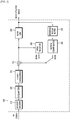
- FIG. 1 is a block diagram showing an example of a structure of an encoder according to an exemplary embodiment of the present invention.
- the encoder 100 includes a motion predictor 111, a motion compensator 112, an intra predictor 120, a switch 115, a subtracter 125, a transformer 130, a quantizer 140, an entropy encoder 150, a dequantizer 160, an inverse transformer 170, an adder 175, a filter unit 180, and a reference picture buffer 190.
- the encoder 100 encodes input images in an intra prediction mode or an inter prediction mode to encoder output a bitstream.
- the intra prediction means intra-picture prediction and the inter prediction means inter-picture prediction.
- the encoder 100 is switched between the intra prediction mode and the inter prediction mode through switching of the switch 115.
- the encoder 100 generates a predicted block for an input block of the input image and then encodes a residual between the input block and the predicted block.
- the intra predictor 120 performs spatial prediction using pixel values of neighboring blocks which are coded already to generate predicted blocks.
- the motion predictor 111 searches a reference block optimally matched with the input block in a reference picture stored in the reference picture buffer 190 during a motion prediction process to obtain a motion vector.
- the motion compensator 112 performs motion-compensation using the motion vector to generate the predicted block.
- the motion vector may be a two dimensional vector used for inter prediction and represent an offset between a current coding treeblock and the reference block.
- the subtracter 125 generate a residual block based on the residual between the input block and the predicted block, and the transformer 130 transforms the residual block to output a transform coefficient.
- the quantizer 140 quantizes the transform coefficient to output the quantized coefficient.
- the entropy encoder 150 performs entropy encoding based on information obtained during an encoding/quantizing process to output the bitstream.
- the entropy encoding represents frequently generated symbols as a small number of bits, thereby reducing a size of a bitstream for a coding symbol. Therefore, the compression performance of a video may be expected to be improved through the entropy encoding.
- the entropy encoder 150 may use an encoding method such as exponential golomb, context-adaptive variable length coding (CAVLC), context-adaptive binary arithmetic coding (CABAC), or the like, for the entropy encoding.
- a coded picture needs to be again decoded and stored in order to be used as a reference picture for performing the inter prediction coding. Therefore, the dequantizer 160 dequantizes the quantized coefficient, and the inverse transformer 170 inversely transforms the dequantized coefficient to output a reconstructed residual block. The adder 175 adds the reconstructed residual block to the predicted block to generate a reconstructed block.
- the filter unit 180 is also called an adaptive in-loop filter and applies at least one of deblocking filtering, sample adaptive offset (SAO) compensation, adaptive loop filtering (ALF) to the reconstructed block.
- deblocking filtering means that block distortion occurred in a boundary between blocks is removed
- SAO compensation means that an appropriate offset is added to a pixel value in order to compensate for a coding error.
- ALF means that filtering is performed based on a comparison value between a reconstructed image and an original image.
- the reference picture buffer 190 stores the reconstructed block passing through the filter unit 180 therein.
- FIG. 2 is a block diagram showing an example of a structure of a decoder according to an exemplary embodiment of the present invention.
- a decoder includes an entropy decoder 210, a dequantizer 220, an inverse transformer 230, an intra predictor 240, a motion compensator 250, an adder 255, a filter unit 260, and a reference picture buffer 270.
- the decoder 200 decodes the bitstream in the intra prediction mode or the inter prediction mode to output a reconstructed image.
- the decoder 200 is switched between the intra prediction mode and the inter prediction mode through switching of the switch.
- the decoder 200 obtains a residual block from the bitstream to generate a predicted block and then adds the residual block and the predicted block to each other to generate a reconstructed block.
- the entropy decoder 210 performs entropy decoding based on probability distribution.
- the entropy decoding process is a process opposite to the above-mentioned entropy encoding process. That is, the entropy decoder 210 generates a symbol including a quantized coefficient from the bitstream in which a frequently generated symbol is represented as a small number of bits.
- the dequantizer 220 dequantizes the quantized coefficient, and the inverse transformer 230 inversely transforms the dequantized coefficient to generate a residual block.
- the intra predictor 240 performs spatial prediction using pixel values of neighboring blocks which are already coded to generate predicted blocks.
- the motion compensator 250 performs the motion-compensation using the motion vector and the reference picture stored in the reference picture buffer 270 to generate the predicted block.
- the adder 255 adds the predicted block to the residual block, and the filter unit 260 applies at least one of deblocking filtering, SAO compensation, ALF to the block passing through the adder to output a reconstructed image.
- the reconstructed image may be stored in the reference picture buffer 270 to thereby be used for the motion-compensation.
- a block means an encoding/decoding unit.
- an image is divided at a predetermined size and then encoded/decoded. Therefore, a block may also be called a coding unit (CU), a prediction unit (PU), a transform unit (TU), or the like, and a single block may also be divided into sub-blocks having a smaller size.
- CU coding unit
- PU prediction unit
- TU transform unit
- a prediction unit means a basic unit in which prediction and/or motion-compensation is performed.
- a prediction unit may be divided into a plurality of partitions, and each of the partitions may also be called a prediction unit partition.
- each of prediction unit partitions may become a basic unit in which prediction and/or motion-compensation are performed.
- a prediction unit may also means prediction unit partitions.
- HEVC high efficiency video coding
- AMVP advanced motion vector prediction
- a motion vector (MV) of a block existing in a position that is the same as or corresponds to that of a coding treeblock, in a reference picture as well as motion vectors of reconstructed blocks positioned around the coding treeblock may be used.
- the block, existing in a position that is the same as or spatially corresponds to that of the coding treeblock, in the reference picture is called a collocated block
- a motion vector of the collocated block is called a collocated motion vector or a temporal motion vector.
- the collocated block may be a block, existing in a position similar to (that is, corresponding to) that of the coding treeblock, in the reference picture as well as a block existing in the same position as that of the coding treeblock.
- motion information is estimated from the collocated block as well as reconstructed blocks positioned around the coding treeblock to thereby be used as motion information of the coding treeblock.
- the motion information includes at least one of inter prediction mode information indicating a reference picture index, a motion vector, a uni-direction, a bi-direction, or the like, required at the time of inter prediction, a reference picture list, and prediction mode information on whether encoding is performed in an intra prediction mode or in an inter prediction mode.
- a predicted motion vector in the coding treeblock may be a motion vector of the collocated block, which is a block temporally adjacent to the coding treeblock, as well as motion vectors of neighboring blocks spatially adjacent to the coding treeblock.
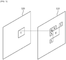
- FIG. 3 shows examples of a coding/decoding object picture and a reference picture.
- a block X indicates a coding treeblock in an encoding/decoding object picture 310
- a block A, a block B, a block C, a block D, and a block E indicate reconstructed blocks positioned around the coding treeblock
- a block T in the reference picture 320 indicates a collocated block existing in a position corresponding to that of the coding treeblock.
- motion vector predictor indices mvp_idx_l0 and mvp_idx_l1 for each reference picture list are transmitted to a decoder, and the decoder uses the same motion vector as a motion vector predicted by an encoder as a predicted motion vector.
- the motion vector may be stored only with a memory having a relative small size.
- a temporal motion vector since all motion vectors of the reference picture needs to be stored in a memory, a memory having a relatively large size is required, and a size of a memory access bandwidth required to fetch data from the memory also increases. Therefore, there is a need to more efficiently store the temporal motion vector in an application environment in which a memory space of a portable terminal, or the like, is not sufficient or power consumption is minimized.
- the motion vector is compressed in any ratio and then stored in the memory.
- a motion vector stored in a 4x4 block unit is stored in a 4x4 or more block unit to reduce the number of stored motion vectors.
- information on a compression ratio is transmitted.
- the information is transmitted through a sequence parameter set (SPS) as shown in Table 2.
- SPS sequence parameter set
- motion_vector_buffer_comp_flag 0 u(1) if ( motion_vector_buffer_comp_flag ) motion_vector_buffer_comp_ratio_log2 0 u(8) rbsp_trailing_bits( ) 0 ⁇
- motion_vector_buffer_comp_ratio_log2 indicates a compression ratio of the motion vector buffer compressing process.
- motion_vector_buffer_comp_ratio_log2 is estimated to 0, and a motion vector buffer compressing ratio is represented by Equation 1.
- MVBufferCompRatio 1 ⁇ ⁇ motion_vector_buffer_comp_ratio_log 2
- the method of reducing a spatial resolution of a motion vector as described above, it is possible to reduce the size of the required memory space and the memory access bandwidth using spatial correlation of the motion vector.
- the method of reducing a spatial resolution of a motion vector does not limit the dynamic range of the motion vector.
- a size of the memory space required in the above-mentioned example is reduced to about 0.8 Mbytes.
- the size of the required memory space may be further reduced to 0.37 Mbytes.
- the dynamic range of the motion vector is limited in order to reduce a size of a memory space required for storing the motion vector and a memory access bandwidth required for fetching data from the memory.
- the motion vector of the reference picture of which the dynamic range is limited may be used as a temporal motion vector in the coding treeblock.
- a dynamic range means a range between a minimum value and a maximum value of a negative component or a positive component of a motion vector based on 0, and a bit depth, which indicates a size of a space required for storing the motion vector, means a bit width.
- the motion vector means a motion vector of a reference picture, that is, a temporal motion vector.
- each component of the motion vector is out of the dynamic range, it is represented by the minimum value or the maximum value of the corresponding dynamic range.
- the X component of the motion vector is limited to 256.
- each component of the motion vector has a dynamic range of -32 to +31, such that the motion vector is represented by (-32, 24), which is in its dynamic range.
- each component of the motion vector has a dynamic range of -256 to +255, such that the motion vector is represented by (-49, 142) without a change.
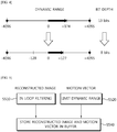
- FIG. 4 shows an example of limiting a dynamic range of a motion vector.
- a bit depth may be reduced from 13 bits to 8 bits.
- Each component of a temporal motion vector is clipped as represented by Equations 2 and 3 in order to be stored in a bit depth of N bit(s).
- N indicates a positive integer.
- clippedMV_X min 1 ⁇ ⁇ N ⁇ 1 ⁇ 1 , max ⁇ 1 ⁇ ⁇ N ⁇ 1
- MV_X clippedMV_Y min 1 ⁇ ⁇ N ⁇ 1 ⁇ 1 , max ⁇ 1 ⁇ ⁇ N ⁇ 1 , MV_Y
- MV_X indicates an X component of the motion vector
- MV_Y indicates a Y component of the motion vector
- min(a,b) means an operation of outputting a smaller value in a and b
- max(a,b) means an operation of outputting a larger value in a and b.
- Each of clippedMV X and clippedMV_Y indicates X and Y components of the clipped temporal motion vector and is stored in the memory to thereby be used as a temporal motion vector of the coding treeblock.
- the dynamic range of the motion vector is limited, such that a motion vector of a reference picture is stored.
- the decoded picture buffer means the reference picture buffer of FIG. 1 or FIG. 2 .
- a process of clipping each component of a motion vector is invoked in the case in which a slice_type is not equal to I.
- the process of clipping a motion vector is performed in a treeblock or largest coding unit (LCU) after a filtering process is finished.
- LCU largest coding unit
- Inputs in the process of clipping a motion vector are a location (xP, yP) specifying the top-left sample of the prediction unit relative to the top-left sample of the current picture, and motion vector matrices MvL0 and MvL1.
- Outputs in the process are the clipped motion vector matrices CMvL0 and CMvL1.
- Equations 4 to 7 operations of Equations 4 to 7 are performed.
- Clip3(a, b, c) means a function of clipping c so as to exist in a range between a and b.
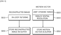
- FIGS. 5 to 8 are flow charts showing a method of storing a motion vector of a reference picture.
- the motion vector of the reference picture may be stored using both of an image buffer storing a reconstructed image and a motion vector buffer storing a motion vector.
- the reconstructed image is subjected to an in-loop filtering process (S510) and the motion vector is subjected to a limiting dynamic range process (S520) and then stored (S540).
- both of an image buffer and a motion vector buffer are used, and the motion vector is subjected to a limiting dynamic range process (S620) and a reducing spatial resolution process (S630) and then stored (S640).
- S620 limiting dynamic range process
- S630 reducing spatial resolution process
- the reconstructed image is subjected to an in-loop filtering process (S710) and then stored in an image buffer (S740), and the motion vector is subjected to a limiting dynamic range process (S720) and then stored in a motion vector buffer (S750).
- S710 in-loop filtering process
- S740 image buffer
- S720 limiting dynamic range process
- S750 motion vector buffer
- the reconstructed image is subjected to an in-loop filtering process (S810) and then stored in an image buffer (S840), and the motion vector is subjected to a limiting dynamic range process (S820) and a reducing spatial resolution process (S830) and then stored (S850).
- S810 in-loop filtering process
- S840 image buffer
- S820 limiting dynamic range process
- S830 reducing spatial resolution process
- a sequence of the limiting dynamic range process S620 or S820 and the reducing spatial resolution process S630 and S830 is not limited, but may be changed.
- dynamic ranges of each component of the motion vector may be differently limited. For example, only one of a dynamic range of an X component and a dynamic range of a Y component may be limited or the dynamic range of the Y component may be further limited as compared to the dynamic range of the X component.
- the limited dynamic range of the motion vector is transmitted through a sequence parameter set, a picture parameter set (PPS), a slice header, or the like, and the decoder similarly performs limitation of a dynamic range of a temporal motion vector in the sequence, the picture, or the slice.
- a bit depth which is a size of a memory space required for storing the motion vector represented in the dynamic range may also be transmitted.
- the motion vector may be quantized and stored.
- precision of the motion vector is reduced.
- a quantizing method there are uniform quantization in which step sizes are uniform, non-uniform quantization in which step sizes are non-uniform, and the like.
- the step size in the quantization is set to a fixed value predefined between the encoder and the decoder or is transmitted from the encoder to the decoder through the sequence parameter set, the picture parameter set, the slice header, or the like.
- the decoder uses the quantized motion vector as it is or dequantizes and use the quantized motion vector.
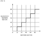
- FIG. 9 shows an example of quantizing a motion vector. Referring to FIG. 9 , in the case in which the motion vector has a component value of 32 to 48, the motion vector is quantized to 40.
- the motion vector may be limited in a representation resolution and the stored.
- the representation resolution means an integer pixel unit (1 pixel unit), a fraction pixel unit (a 1/2 pixel unit, a 1/4 pixel unit, or the like).
- a resolution of the motion vector processed in a 1/4 pixel unit may be stored as an integer pixel.
- the representation resolution of the motion vector is set to a fixed value predefined between the encoder and the decoder or is transmitted from the encoder to the decoder through the sequence parameter set, the picture parameter set, the slice header, or the like.
- a limiting dynamic range process In addition, only with respect to some motion vectors among temporal motion vectors stored in a memory, a limiting dynamic range process, a reducing space resolution process, and a quantizing process of the motion vector may be performed.
- information on the dynamic range of the motion vector may be added and stored in the memory.
- a flag of 1 may be additionally stored
- a flag of 0 may be additionally stored.
- flag information may be stored together with the motion vector or be stored in a memory different from the memory in which the motion vector is stored.
- the flag information and the motion vector are stored in different memories, when in which dynamic range a specific motion vector is stored is recognized, arbitrary access to the flag information may be allowed.
- information on in which dynamic range some motion vectors are stored is transmitted through the sequence parameter set, the picture parameter set, the slice header, or the like, thereby making it possible to allow a decoder to perform an operation similar to that of an encoder.
- information on a block size of the motion vector may be added and stored in the memory.
- a flag of 1 may be additionally stored
- a flag of 0 may be additionally stored.
- flag information may be stored together with the motion vector or be stored in a memory different from the memory in which the motion vector is stored.
- the flag information and the motion vector are stored in different memories, when in which block size a specific motion vector is stored is recognized, arbitrary access to the flag information may be allowed.
- information on in which block size some motion vectors are stored is transmitted through the sequence parameter set, the picture parameter set, the slice header, or the like, thereby making it possible to allow a decoder to perform an operation similar to that of an encoder.
- information on precision of the motion vector may be added and stored in the memory.
- a flag of 1 may be additionally stored
- a flag of 0 may be additionally stored.
- flag information may be stored together with the motion vector or be stored in a memory different from the memory in which the motion vector is stored.
- the flag information and the motion vector are stored in different memories, when at which step size a specific motion vector is quantized and stored is recognized, arbitrary access to the flag information may be allowed.
- information on at which step size some motion vectors are quantized and stored is transmitted through the sequence parameter set, the picture parameter set, the slice header, or the like, thereby making it possible to allow a decoder to perform an operation similar to that of an encoder.
- the spatial resolution of the motion vector may be reduced and stored.
- the motion information includes at least one of inter prediction mode information indicating a reference picture index, a motion vector, a uni-direction, a bi-direction, or the like, required at the time of inter prediction, a reference picture list, and prediction mode information on whether an intra prediction mode is performed or an inter prediction mode is performed.
- motion information of a prediction unit having the largest partition size among a plurality of motion information of a specific region may be stored as representative motion information in the memory.
- the specific region may include a region in the coding treeblock and regions of neighboring blocks of the coding treeblock.
- the specific region may be a region including a block in which the motion information is stored in the case in which the entire picture or slice is divided at a predetermined size.
- the representative motion information may be stored in the memory.
- the most frequently generated motion information among the plurality of motion information included in the specific region may be stored as the representative motion information in the memory.
- the number of generation of the motion information for each size of the block, or the like may be calculated.
- motion information at a specific position among the plurality of motion information included in the specific region may be stored.
- the specific position which is a position included in the specific region, may be a fixed position of the specific region.
- the specific position may be selected as one of a plurality of positions. When the plurality of positions are used, a priority for each position may be determined, and the motion information may be stored in the memory according to the priority.
- the motion information included in the specific region is stored in the memory, since the motion information does not exist outside a boundary of a block coded in an intra prediction mode, a block coded in a pulse coded modulation (PCM) mode, a slice, or a picture, the motion information of the corresponding position may not be stored in the memory.
- PCM pulse coded modulation
- the specific position may be one sample position in a neighboring block or a position of the block.
- a medium value or average value among motion information of neighboring blocks which are coded in inter prediction may be stored in the memory.
- an average value of motion information of neighboring blocks may be stored in the memory.
- a size of the motion vector may be adjusted according to the reference picture index, the reference picture list, the inter prediction mode information, a picture order count, and the like.
- the stored motion information may be fetched.
- motion information of a position corresponding to that of the coding treeblock in the reference picture may be fetched.
- the position corresponding to that of the coding treeblock in the reference picture may be a fixed position in a specific region or a relative position from the position of the coding treeblock.
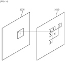
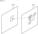
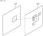
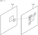
- a block X indicates a coding treeblock in an encoding/decoding object picture 1010, 1110, 1210, or 1310, and a block A, a block B, a block C, a block D, and a block E indicate reconstructed neighboring blocks.
- a block T in the reference picture 1020, 1120, 1220, and 1320 indicates a collocated block corresponding to the coding treeblock.
- a block Y in the reference picture 1320 of FIG. 13 indicates a block corresponding to a position other than the encoding/decoding object block.
- motion information corresponding to a position corresponding to a top-left pixel position among positions of a coding treeblock X in a reference picture may be fetched.
- motion information corresponding to a position corresponding to a central pixel position among positions of a coding treeblock X in a reference picture may be fetched.
- motion information corresponding to a position corresponding to a pixel position other than a coding treeblock X in a reference picture may be fetched.
- An encoding/decoding method such as motion vector prediction, advanced motion vector prediction, motion information merge, motion information merge skip, or the like, may be performed using the motion information stored in the memory, that is, the motion information of the reference picture.
- the motion vector may be stored in the memory using at least one of a method of limiting a dynamic range of a motion vector, a method of reducing a spatial resolution of a motion vector, a method of quantizing a motion vector, and a method of reducing a representation resolution of a motion vector, and the stored motion vector may be used for predicting a motion vector of the coding treeblock and merging motion information thereof.
- a process of fetching the motion vector of the reference picture from the memory is called a process of deriving a temporal motion vector.
- TMVbitWidth indicates a bit width of a temporal motion vector stored in the memory.
- Inputs in the process of deriving a temporal motion vector are a location (xP, yP) specifying the top-left luma sample of the current prediction unit relative to the top-left sample of the current picture, variables specifying the width and the height of the prediction unit for luma, nPSW and nPSH, the reference index of the current prediction unit partition refIdxLX (with X being 0 or 1).
- Outputs in the process are the motion vector prediction mvLXCol and the availability flag availableFlagLXCol.
- the function RefPicOrderCnt(pic, refidx, LX) is specified by the value of PicOrderCnt of the picture that is the reference picture RefPicListX[refidx] of pic with X being 0 or 1. PicOrderCnt of the reference picture shall be maintained until the picture is marked as "non-exisiting.”
- Clip3(a, b, c) means a function of clipping c so as to exist in a range between a and b.
- variable colPic specifies the picture that contains the co-located partition as specified by RefPicList1[0]. Otherwise (slice_type is equal to B and collocated_from_10_flag is equal to 1 or slice_type is equal to P), the variable colPic specifies the picture that contains the co-located partition as specified by RefPicList0[0].
- Variable colPu and its position are derived in the following ordered steps:
- mvLXCol is derived as scaled version of the motion vector mvCol.
- Equations 15 and 16 may be replaced with Equations 19 and 20.
- Equations 15 and 16 may be replaced with Equations 19 and 20.
- mvLXCol ⁇ ClipMv DistScaleFactor * mvLXCol + 128 > > 8
- mvLXCol Clip 3 ⁇ 1 ⁇ ⁇ TMVBitWidth ⁇ 1 , 1 ⁇ ⁇ TMVBitWidth ⁇ 1 ⁇ 1 , mvCol ⁇
- TMVBitWidth in the process of deriving a temporal motion vector may be transmitted from the encoder to the decoder through a sequence parameter set, a picture parameter set, a slice header, or the like.
- [Table 5] seq_parameter_set_rbsp( ) ⁇ C Descriptor ; bit_width_temporal_motion_vector_minus8 0 se(v) ; rbsp_trailing_bits( ) 0 ⁇
- bit_width_temporal_motion_vector_minus8 of Table 5 specifies the bit width of the temporal motion vector component. When bit_width_temporal_motion_vector_minus8 is not present, it shall be inferred to be equal to 0.
- motion vector buffer_comp_flag 0 u(1) if ( motion_vector_buffer_comp_flag ) motion_vector_buffer comp_ratio_log2 0 u(8) bit_depth_temporal_motion_vector_constraint_flag 0 u(1) if (bit_depth_temporal_motion_vector_constraint_ftag ) bit_depth_temporal_motion vector_minus8 0 se(v) whereas rbsp_trailing_bits( ) 0 ⁇ Referring to Table 6, in the case in which motion_vector_buffer_comp_flag equals to 1 specifies the motion vector buffer compression process is applied.
- motion_vector_buffer_comp_ratio_log2 specifies the compression ratio in the motion vector buffer compression process. When motion_vector_buffer_comp_ratio_log2 is not present, it shall be inferred to be equal to 0.
- bit_depth_temporal_motion_vector_constraint_flag 1 specifies the temporal motion vector bit depth limiting constraint process is applied.
- bit_depth_temporal_motion_vector_minus8 specifies the bit depth of the temporal motion vector.
- bit_depth_temporal_motion_vector_minus8 When bit_depth_temporal_motion_vector_minus8 is not present, it shall be inferred to be equal to 0.
- Information transmitting method 2 in the case in which bit depth of motion vector is limited [Table 7] seq parameter_set_rbsp( ) ⁇ C Descriptor ; bit_depth_temporal_motion_vector_constraint_flag 0 u(1) if (bit_depth_temporal_ mot ion_vector_constraint_flag ) bit_depth_temporal_motion_vector_minus8 0 se(v) ).
- bit_depth_temporal_motion_vector_constraint_flag 1 specifies the temporal motion vector bit depth constraint process is applied.
- bit_depth_temporal_motion_vector_minus8 specifies the bit depth of the temporal motion vector. When bit_depth_temporal_motion_vector_minus8 is not present, it shall be inferred to be equal to 0.
- bit_depth_temporal_motion_vector_minus8 specifies the bit depth of the temporal motion vector.
- bit_depth_temporal_motion_vector_minus8 When bit_depth_temporal_motion_vector_minus8 is not present, it shall be inferred to be equal to 0.
- bit_depth_temporal_motion_vector_constraint_flag 0 u(1) if (bit_depth_temporal_motion_vector_constraint_flag ) ⁇ bit_depth temporal_motion_vector_x_ minus8 0 se(v) bit_depth_temporal_motion_vector_y_minus8 0 se(v) ⁇ ...
- bit_depth_temporal_motion_vector_constraint_flag 1 specifies the temporal motion vector bit depth constraint process is applied.
- bit_depth_temporal_motion_vector_x_minus8 specifies the bit depth of the temporal motion vector component x. When bit_depth_temporal_motion_vector_x_minus8 is not present, it shall be inferred to be equal to 0.
- motion_vector_buffer comp_flag 1 specifies the motion vector buffer compression process is applied.
- motion_vector_buffer_comp_ratio_log2 specifies the compression ratio in the motion vector buffer compression process. When motion_vector_buffer_comp_ratio_log2 is not present, it shall be inferred to be equal to 0.
- the dynamic range of the temporal motion vector may be defined through a level of a video codec rather than being transmitted through the sequence parameter set, the picture parameter set, or the slice header.
- the encoder and the decoder may determine a limited dynamic range of the motion vector using level information.
- dynamic ranges and/or bit depths of each of the X and Y components of the motion vector may be differently defined, and minimum values and maximum values of each of the components may be defined.
- Tables 11 and 12 show an example of a case in which TMVBitWidth in the process of deriving a temporal motion vector described above is defined in the levels.
- Level number MaxTMVBitWidth (Max Temporal MV component bit width) 1 8 1b 8 1.1 8 1.2 8 1.3 8 2 8 2.1 8 2.2 8 3 8 3.1 10 3.2 10 4 10 4.1 10 4.2 10 5 10 5.1 10
- TMVBitWidth is set as MaxTMVBitWidth defined in the levels.
- MaxTMVBitWidth indicates a maximum bit width of a temporal motion vector when the temporal motion vector is stored in the memory.
- TMVBitWidth may also be defined in the levels, and a difference from the defined value (a delta value) may be transmitted through the sequence parameter set, the picture parameter set, or the slice header. That is, TMVBitWidth may be set to as a value obtained by adding the difference transmitted through the sequence parameter set, the picture parameter set, or the slice header to MaxTMVBitWidth defined in the levels.
- TMVBitWidth indicates a bit width of the temporal motion vector when the temporal motion vector is stored in the memory.
- delta_bit_width_temporal_motion_vector_minus8 specifies the delta bit width of the temporal motion vector component. When delta_bit_width_temporal_motion_vector_minus8 is not present, it shall be inferred to be equal to 0.
- dynamic ranges of each component of the temporal motion vector may also be defined in levels.
- Level number MaxMBPS Max macroblock processing rate
- MB/s MaxFS (Max picture size)
- MBs MaxDpbMbs (Max decoded picture buffer size)
- MaxBR Max video bit rate
- Max CPB size 1000 bits, 1200 bits, pbBrVdFactor bits, or cpbBrNalFactor bits/s
- MaxCPB Max CPB size
- MaxTmvR Max Temporal MV component range
- MinCR Min compression ratio
- MaxMvsPer2Mb Max number of motion vectors per two consecutive MBs
- a bit width of a Y component of the temporal motion vector may also be defined in levels.
- Level number MaxMBPS Max macroblock processing rate
- MB/s MaxFS (Max picture size)
- MBs MaxDpbMbs (Max decoded picture buffer size)
- MBs MaxBR (Max video bit rate) (1000 bits/s, 1200 bits/s, cpbBrVclFactor bits/s, or cpbBrNalFactor bits/s)
- MaxCPB Max CPB size
- MaxTMVYBitWidth Max Vertical Temporal MV component bit depth
- MinCR Min compression ratio
- MaxMvsPer2Mb Max number of motion vectors per two consecutive MBs
- TMVBitWidth In the case in which TMVBitWidth is fixed to the same value and used in the encoder and the decoder, TMVBitWidth may be a positive integer such as 4, 6, 8, 10, 12, 14, 16, or the like.
- TMVBitWidth indicates the bit width of the temporal motion vector when the temporal motion vector is stored in the memory.
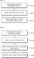
- FIG. 14 is a flow chart showing a method of encoding an image according to the exemplary embodiment of the present invention.
- the method of encoding an image includes a clipping step (S 1410), a storing step (S1420), and an encoding step (S1430).
- the apparatus of encoding an image and/or the apparatus of decoding an image store the clipped motion vector of the reference picture in a buffer as described above through "II. Process of storing motion vector" (S 1420).
- the motion vector may be stored in the buffer together with or separately from the reconstructed image.
- the apparatus of encoding an image encodes a motion vector of a coding treeblock using the stored motion vector of the reference picture (S1430).
- a motion vector of a block existing in a position that is the same or corresponds to that of the coding treeblock in the reference picture as well as motion vectors of reconstructed blocks positioned around the coding treeblock may be used. Therefore, the motion vector of the coding treeblock may also be a motion vector of the reference picture, that is, a temporal motion vector, as well as motion vectors of neighboring blocks adjacent to the coding treeblock.
- each component of the motion vector of the reference picture may be clipped in each dynamic range.
- a method of compressing a motion vector of a reference picture as well as a method of limiting a dynamic range of a motion vector of a reference picture may be used.
- a flag indicating the dynamic range and the motion vector and a parameter related thereto may be defined in a level of a video codec, a sequence parameter set, or the like.
- an encoding method such as motion vector prediction, advanced motion vector prediction, motion information merge, motion information merge skip, or the like, may be performed using the motion information stored in the memory, that is, the motion information of the reference picture.
- FIG. 15 is a flow chart showing a method of decoding an image according to the exemplary embodiment of the present invention.
- the method of decoding an image includes a clipping step (S1510), a storing step (S 1520), a deriving step (S1530), and a decoding step (S1540).
- the clipping step (S1510) and the storing step (S1520) of FIG. 15 are similar to the clipping step (S1410) and the storing step (S1420) of FIG. 14 using "I. Process of clipping motion vector” and “II. Process of storing motion vector” described above.
- the deriving step (S1530) of FIG. 15 uses “III. Process of deriving motion vector” described above and is symmetrical to the encoding step (S1430) of FIG. 14 . Therefore, a detailed description thereof will be omitted.
- An apparatus of decoding an image performs inter prediction decoding using a motion vector of a coding treeblock (S 1540).
- the apparatus of decoding an image may store a motion vector in a memory using at least one of a method of limiting a dynamic range of a motion vector, a method of reducing a spatial resolution of a motion vector, a method of quantizing a motion vector, and a method of reducing a representation resolution of a motion vector, and use the stored motion vector for predicting a motion vector of the coding treeblock and merging motion information thereof.
- the apparatus of decoding an image may perform a decoding method such as motion vector prediction, advanced motion vector prediction, motion information merge, motion information merge skip, or the like, using the motion information stored in the memory, that is, the motion information of the reference picture.
- a decoding method such as motion vector prediction, advanced motion vector prediction, motion information merge, motion information merge skip, or the like, using the motion information stored in the memory, that is, the motion information of the reference picture.
Landscapes
- Engineering & Computer Science (AREA)
- Multimedia (AREA)
- Signal Processing (AREA)
- Compression Or Coding Systems Of Tv Signals (AREA)
Abstract
Description
- The present invention relates to image processing, and more particularly, to a video coding/decoding method using a clipped motion vector and an apparatus thereof.
- Recently, in accordance with the expansion of a broadcasting system supporting high definition (HD) resolution in the country and around the world, many users have been accustomed to a high resolution and definition image, such that many organizations have conducted many attempts to develop the next-generation video devices. In addition, as the interest in HDTV and ultra high definition (UHD) having a resolution four times higher than that of HDTV has increased, a compression technology for a higher-resolution and higher-definition video has been demanded.
- For image compression, an inter prediction technology of predicting pixel values included in a current picture from a picture before and/or after the current picture, an intra prediction technology of predicting pixel values using pixel information in the picture, an entropy coding technology of allocating a short code to a symbol having a high appearance frequency and a long code to a symbol having a low appearance frequency, or the like, may be used.
- The prevent invention provides a video coding/decoding method using a clipped motion vector and an apparatus thereof.
- The present invention also provides a method for clipping a motion vector of a reference picture.
- The present invention also provides a method for transmitting information on a motion vector.
-
- 1. An embodiment of the present invention relates to a method of encoding an image. The method includes clipping a motion vector of a reference picture in a predetermined dynamic range to generate a clipped motion vector, storing the clipped motion vector in a buffer and encoding a motion vector of a coding treeblock using the motion vector stored in the buffer.
- 2. In 1, the dynamic range may be defined by a level of a video codec.
- 3. In 1, the dynamic range may be determined by a predetermined bit depth, and the bit depth may be defined by a level of a video codec.
- 4. In 1, X-component and Y-component of motion vector of the reference picture may be clipped in different dynamic ranges.
- 5. Another embodiment of the present invention relates to a method of decoding an image. The method includes clipping a motion vector of a reference picture in a predetermined dynamic range to generate a clipped motion vector, storing the clipped motion vector in a buffer, deriving a motion vector of a coding treeblock using the motion vector stored in the buffer, and performing inter prediction decoding process using the motion vector of the coding treeblock.
- 6. In 5, the dynamic range may be defined by a level of a video codec.
- 7. In 5, the dynamic range may be determined by a predetermined bit depth, and the bit depth may be defined by a level of a video codec.
- 8. In 5, the dynamic range may be determined by a predetermined bit depth, and the bit depth may be obtained through a sequence parameter set transmitted from an apparatus of encoding an image.
- 9. In 8, the sequence parameter set may include a flag indicating whether the motion vector of the reference picture is clipped and a parameter for obtaining the bit depth.
- 10. In 9, the method of decoding an image may include compressing the motion vector of the reference picture, wherein the sequence parameter set includes a flag indicating whether the motion vector of the reference picture is compressed and a parameter for obtaining a compression ratio of the motion vector of the reference picture.
- 11. In 5, the method of decoding an image may include limiting a representation resolution of the motion vector of the reference picture.
- 12. In 5, the clipped motion vector may be stored according to a priority.
- 13. In 5, the clipped motion vector may be a motion vector of a block coded in inter prediction mode.
- 14. In 5, the method of decoding an image may include performing scaling the motion vector of the reference picture.
- 15. In 5, X-component and Y-component of motion vector of the reference picture may be clipped in different dynamic ranges.
- 16. In 15, the dynamic range of the X-component and the dynamic range of the Y-component may be defined by a level of a video codec.
- 17. Yet another embodiment of the present invention relates to an apparatus of decoding an image. The apparatus includes a reference picture buffer storing a reference picture and a motion compensator generating a predicted block using the reference picture and a motion vector of the reference picture, wherein the motion vector of the reference picture is clipped in a predetermined dynamic range.
- 18. In 17, the dynamic range may be defined by a level of a video codec.
- 19. In 17, the dynamic range may be determined by a predetermined bit depth, and the bit depth may be defined by a level of a video codec.
- 20. In 17, the dynamic range may be determined by a predetermined bit depth, and the bit depth may be obtained through a sequence parameter set transmitted from an apparatus of encoding an image.
- According to the exemplary embodiment of the present invention, the video may be coded using the clipped motion vector.
- According to the exemplary embodiment of the present invention, a size of a memory required for storing motion vectors may be reduced.
- According to the exemplary embodiment of the present invention, a memory access bandwidth required for fetching data from the memory may be reduced.
-
-
FIG. 1 is a block diagram showing an example of a structure of an encoder according to an exemplary embodiment of the present invention. -
FIG. 2 is a block diagram showing an example of a structure of a decoder according to an exemplary embodiment of the present invention. -
FIG. 3 shows examples of a coding/decoding object picture and a reference picture. -
FIG. 4 shows an example of limiting a dynamic range of a motion vector. -
FIGS. 5 to 8 are flow charts showing a method of storing a motion vector of a reference picture. -
FIG. 9 shows an example of quantizing a motion vector. -
FIGS. 10 to 13 show examples of fetching motion information from a reference picture. -
FIG. 14 is a flow chart showing a method of encoding an image according to the exemplary embodiment of the present invention. -
FIG. 15 is a flow chart showing a method of decoding an image according to the exemplary embodiment of the present invention. - Hereinafter, exemplary embodiments of the present invention will be described in detail with reference to the accompanying drawings. However, in describing exemplary embodiments of the present invention, well-known functions or constructions will not be described in detail since they may unnecessarily obscure the understanding of the present invention.
- It is to be understood that when any element is referred to as being "connected to" or "coupled to" another element, it may be connected directly to or coupled directly to another element or be connected to or coupled to another element, having the other element intervening therebetween. Further, in the present specification, in the case of describing "including" a specific component, it is to be understood that additional components other than a corresponding component are not excluded, but may be included in exemplary embodiments or the technical scope of the present invention.
- Terms used in the specification, 'first', 'second', etc., may be used to describe various components, but the components are not to be construed as being limited to the terms. That is, the terms are used to distinguish one component from another component. For example, the 'first' component may be named the 'second' component, and vice versa, without departing from the scope of the present invention.
- In addition, components described in exemplary embodiments of the present invention are independently shown only in order to indicate that they perform different characteristic functions. Therefore, the components that are independently shown do not mean that each of the components may not be implemented as one hardware or software. That is, each of the components is divided for convenience of explanation, a plurality of components may be combined with each other to thereby be operated as one component or one component may be divided into a plurality components to thereby be operated as the plurality of components, which are included in the scope of the present invention as long as it departs from essential characteristics of the present invention.
- In addition, some of components may not be indispensable components performing essential functions of the present invention, but be selective components improving only performance thereof. The present invention may also be implemented only by a structure including the indispensible components except for the selective components, and the structure including only the indispensible components is also included in the scope of the present invention.
-
FIG. 1 is a block diagram showing an example of a structure of an encoder according to an exemplary embodiment of the present invention. - Referring to
FIG. 1 , theencoder 100 includes amotion predictor 111, amotion compensator 112, anintra predictor 120, aswitch 115, asubtracter 125, atransformer 130, aquantizer 140, anentropy encoder 150, adequantizer 160, aninverse transformer 170, anadder 175, afilter unit 180, and areference picture buffer 190. - The
encoder 100 encodes input images in an intra prediction mode or an inter prediction mode to encoder output a bitstream. The intra prediction means intra-picture prediction and the inter prediction means inter-picture prediction. Theencoder 100 is switched between the intra prediction mode and the inter prediction mode through switching of theswitch 115. Theencoder 100 generates a predicted block for an input block of the input image and then encodes a residual between the input block and the predicted block. - In the case of the intra prediction mode, the
intra predictor 120 performs spatial prediction using pixel values of neighboring blocks which are coded already to generate predicted blocks. - In the case of the inter prediction mode, the
motion predictor 111 searches a reference block optimally matched with the input block in a reference picture stored in thereference picture buffer 190 during a motion prediction process to obtain a motion vector. Themotion compensator 112 performs motion-compensation using the motion vector to generate the predicted block. Here, the motion vector may be a two dimensional vector used for inter prediction and represent an offset between a current coding treeblock and the reference block. - The
subtracter 125 generate a residual block based on the residual between the input block and the predicted block, and thetransformer 130 transforms the residual block to output a transform coefficient. Thequantizer 140 quantizes the transform coefficient to output the quantized coefficient. - The
entropy encoder 150 performs entropy encoding based on information obtained during an encoding/quantizing process to output the bitstream. The entropy encoding represents frequently generated symbols as a small number of bits, thereby reducing a size of a bitstream for a coding symbol. Therefore, the compression performance of a video may be expected to be improved through the entropy encoding. Theentropy encoder 150 may use an encoding method such as exponential golomb, context-adaptive variable length coding (CAVLC), context-adaptive binary arithmetic coding (CABAC), or the like, for the entropy encoding. - A coded picture needs to be again decoded and stored in order to be used as a reference picture for performing the inter prediction coding. Therefore, the
dequantizer 160 dequantizes the quantized coefficient, and theinverse transformer 170 inversely transforms the dequantized coefficient to output a reconstructed residual block. Theadder 175 adds the reconstructed residual block to the predicted block to generate a reconstructed block. - The
filter unit 180 is also called an adaptive in-loop filter and applies at least one of deblocking filtering, sample adaptive offset (SAO) compensation, adaptive loop filtering (ALF) to the reconstructed block. The deblocking filtering means that block distortion occurred in a boundary between blocks is removed, and the SAO compensation means that an appropriate offset is added to a pixel value in order to compensate for a coding error. In addition, the ALF means that filtering is performed based on a comparison value between a reconstructed image and an original image. - Meanwhile, the
reference picture buffer 190 stores the reconstructed block passing through thefilter unit 180 therein. -
FIG. 2 is a block diagram showing an example of a structure of a decoder according to an exemplary embodiment of the present invention. - Referring to
FIG. 2 , a decoder includes anentropy decoder 210, adequantizer 220, aninverse transformer 230, anintra predictor 240, amotion compensator 250, anadder 255, afilter unit 260, and areference picture buffer 270. - The
decoder 200 decodes the bitstream in the intra prediction mode or the inter prediction mode to output a reconstructed image. Thedecoder 200 is switched between the intra prediction mode and the inter prediction mode through switching of the switch. Thedecoder 200 obtains a residual block from the bitstream to generate a predicted block and then adds the residual block and the predicted block to each other to generate a reconstructed block. - The
entropy decoder 210 performs entropy decoding based on probability distribution. The entropy decoding process is a process opposite to the above-mentioned entropy encoding process. That is, theentropy decoder 210 generates a symbol including a quantized coefficient from the bitstream in which a frequently generated symbol is represented as a small number of bits. - The
dequantizer 220 dequantizes the quantized coefficient, and theinverse transformer 230 inversely transforms the dequantized coefficient to generate a residual block. - In the case of the intra prediction mode, the
intra predictor 240 performs spatial prediction using pixel values of neighboring blocks which are already coded to generate predicted blocks. - In the case of the inter prediction mode, the
motion compensator 250 performs the motion-compensation using the motion vector and the reference picture stored in thereference picture buffer 270 to generate the predicted block. - The
adder 255 adds the predicted block to the residual block, and thefilter unit 260 applies at least one of deblocking filtering, SAO compensation, ALF to the block passing through the adder to output a reconstructed image. - The reconstructed image may be stored in the
reference picture buffer 270 to thereby be used for the motion-compensation. - Hereinafter, a block means an encoding/decoding unit. In an encoding/decoding process, an image is divided at a predetermined size and then encoded/decoded. Therefore, a block may also be called a coding unit (CU), a prediction unit (PU), a transform unit (TU), or the like, and a single block may also be divided into sub-blocks having a smaller size.
- Here, a prediction unit means a basic unit in which prediction and/or motion-compensation is performed. A prediction unit may be divided into a plurality of partitions, and each of the partitions may also be called a prediction unit partition. When a prediction unit is divided into the plurality of partitions, each of prediction unit partitions may become a basic unit in which prediction and/or motion-compensation are performed. Hereinafter, in the exemplary embodiment of the present invention, a prediction unit may also means prediction unit partitions.
- Meanwhile, in high efficiency video coding (HEVC), a motion vector prediction method based on advanced motion vector prediction (AMVP) is used.
- In the motion vector prediction method based on advanced motion vector prediction, a motion vector (MV) of a block, existing in a position that is the same as or corresponds to that of a coding treeblock, in a reference picture as well as motion vectors of reconstructed blocks positioned around the coding treeblock may be used. Here, the block, existing in a position that is the same as or spatially corresponds to that of the coding treeblock, in the reference picture is called a collocated block, and a motion vector of the collocated block is called a collocated motion vector or a temporal motion vector. However, the collocated block may be a block, existing in a position similar to (that is, corresponding to) that of the coding treeblock, in the reference picture as well as a block existing in the same position as that of the coding treeblock.
- In a motion information merge method, motion information is estimated from the collocated block as well as reconstructed blocks positioned around the coding treeblock to thereby be used as motion information of the coding treeblock. Here, the motion information includes at least one of inter prediction mode information indicating a reference picture index, a motion vector, a uni-direction, a bi-direction, or the like, required at the time of inter prediction, a reference picture list, and prediction mode information on whether encoding is performed in an intra prediction mode or in an inter prediction mode.
- A predicted motion vector in the coding treeblock may be a motion vector of the collocated block, which is a block temporally adjacent to the coding treeblock, as well as motion vectors of neighboring blocks spatially adjacent to the coding treeblock.
-
FIG. 3 shows examples of a coding/decoding object picture and a reference picture. - In
FIG. 3 , a block X indicates a coding treeblock in an encoding/decoding object picture 310, and a block A, a block B, a block C, a block D, and a block E indicate reconstructed blocks positioned around the coding treeblock. In addition, a block T in thereference picture 320 indicates a collocated block existing in a position corresponding to that of the coding treeblock. - Which motion vector in the coding treeblock is used as the predicted motion vector may be recognized through a motion vector predictor index.
[Table 1] prediction_unit(x0, y0, log2PUWidth, log2PUHeight ) { Descriptor if(skip_flag[ x0 ][ y0] ) { if( NumMVPCand(L0) > 1 ) mvp_idx_l0[ x0 ][ y0 ] ue(v)|ae(v) if( NumMVPCand( L1 ) > 1) mvp_idx_l1[ x0 ][ y0 ] ue(v)|ae(v) } else if( PredMode = = MODE_INTRA ) { ... } else { /*MODE_MERGE, MODE_INTER*/ if( merge_flag[ x0 ][ y0 ] && NumMergeCandidates > 1 ) { ... } else { if( inter_pred_idc[x0][y0] ! =Pred_L1 ) { if( NumMVPCand( L0 ) > 1) mvp_idx_l0 ue(v)|ae(v) } if( inter_pred_idc[x0][y0] !=Pred_L0 ) { if( NumMVPCand(L1) > 1 ) mvp_idx_l1 ue(v)|ae(v) } } } } - As shown in Table 1, motion vector predictor indices mvp_idx_l0 and mvp_idx_l1 for each reference picture list are transmitted to a decoder, and the decoder uses the same motion vector as a motion vector predicted by an encoder as a predicted motion vector.
- In the case in which the coding treeblock is encoded/decoded using the motion vectors of the neighboring blocks spatially adjacent to the coding treeblock, the motion vector may be stored only with a memory having a relative small size. However, in the case in which a temporal motion vector is used, since all motion vectors of the reference picture needs to be stored in a memory, a memory having a relatively large size is required, and a size of a memory access bandwidth required to fetch data from the memory also increases. Therefore, there is a need to more efficiently store the temporal motion vector in an application environment in which a memory space of a portable terminal, or the like, is not sufficient or power consumption is minimized.
- Meanwhile, as a technology of storing a motion vector in a memory, there is a method of reducing a spatial resolution of the motion vector. In this method, the motion vector is compressed in any ratio and then stored in the memory. For example, a motion vector stored in a 4x4 block unit is stored in a 4x4 or more block unit to reduce the number of stored motion vectors. Here, in order to adjust a block size of the stored motion vector, information on a compression ratio is transmitted. The information is transmitted through a sequence parameter set (SPS) as shown in Table 2.
[Table 2] seq_parameter_set_rbsp( ) { C Descriptor ..... motion_vector_buffer_comp_flag 0 u(1) if ( motion_vector_buffer_comp_flag ) motion_vector_buffer_comp_ratio_log2 0 u(8) rbsp_trailing_bits( ) 0 } - Referring to Table 2, in the case in which motion_vector_buffer_comp_flag is 1, a motion vector buffer compressing process is performed.
- motion_vector_buffer_comp_ratio_log2 indicates a compression ratio of the motion vector buffer compressing process. In the case in which the motion_vector_buffer_comp_ratio_log2 does not exist, motion_vector_buffer_comp_ratio_log2 is estimated to 0, and a motion vector buffer compressing ratio is represented by Equation 1.

- For example, in the case in which all 4x4 blocks of 1920x1080 pictures have different motion vectors and use two reference picture lists each using two reference pictures, a total memory space of 3.21 Mbytes is required to store a temporal motion vector as described below.
- 1. Bit depth of 26 bits per one motion vector
- (1) Dynamic range of X component of motion vector: -252 to +7676 (bit depth: 13 bits)
- (2) Dynamic range of Y component of motion vector: -252 to +4316 (bit depth: 13 bits)
- (3) (The dynamic ranges of each component of the motion vector were calculated based on a first prediction unit in a corresponding picture.)
- 2. In the case in which all of 4x4 block units have different motion vectors: 480 x 270 = 129600 blocks
- 3. Use of two motion vectors per each block
- 4. The number of reference picture lists: 2
- 5. Use of two reference pictures per reference picture list
=> 26 bits x 129600 blocks x two motion vectors x two reference picture lists x two reference pictures = 26956800 bits = 3.21 Mbytes - According to the method of reducing a spatial resolution of a motion vector as described above, it is possible to reduce the size of the required memory space and the memory access bandwidth using spatial correlation of the motion vector. However, the method of reducing a spatial resolution of a motion vector does not limit the dynamic range of the motion vector.
- When the size of the memory space is reduced to 1/4, a size of the memory space required in the above-mentioned example is reduced to about 0.8 Mbytes. Here, when only six bits of the bit depth required for storing the motion vector is used for each component of the motion vector by additionally limiting the dynamic range of the motion vector, the size of the required memory space may be further reduced to 0.37 Mbytes.
- Therefore, in the exemplary embodiment of the present invention, the dynamic range of the motion vector is limited in order to reduce a size of a memory space required for storing the motion vector and a memory access bandwidth required for fetching data from the memory. The motion vector of the reference picture of which the dynamic range is limited may be used as a temporal motion vector in the coding treeblock.
- Hereinafter, a dynamic range means a range between a minimum value and a maximum value of a negative component or a positive component of a motion vector based on 0, and a bit depth, which indicates a size of a space required for storing the motion vector, means a bit width. In addition, unless particularly described, the motion vector means a motion vector of a reference picture, that is, a temporal motion vector.
- In the case in which each component of the motion vector is out of the dynamic range, it is represented by the minimum value or the maximum value of the corresponding dynamic range. For example, in the case in which an X component of the motion vector 312 and a maximum value of a dynamic range of each component of the motion vector 256, the X component of the motion vector is limited to 256.
- Likewise, in the case in which a bit depth of each component of the motion vector is 16 bits and the motion vector is (-36, 24), when the bit depth of each component of the motion vector is limited to 6 bits, each component of the motion vector has a dynamic range of -32 to +31, such that the motion vector is represented by (-32, 24), which is in its dynamic range.
- Further, in the case in which a bit depth of each component of the motion vector is 16 bits and the motion vector is (-49, 142), when the bit depth of each component of the motion vector is limited to 9 bits, each component of the motion vector has a dynamic range of -256 to +255, such that the motion vector is represented by (-49, 142) without a change.
-
FIG. 4 shows an example of limiting a dynamic range of a motion vector. - Referring to
FIG. 4 , when a dynamic range of a motion vector having a dynamic range of -4096 to +4095 is limited to -128 to +127, a bit depth may be reduced from 13 bits to 8 bits. - Each component of a temporal motion vector is clipped as represented by Equations 2 and 3 in order to be stored in a bit depth of N bit(s). Where N indicates a positive integer.


- Where MV_X indicates an X component of the motion vector, MV_Y indicates a Y component of the motion vector, min(a,b) means an operation of outputting a smaller value in a and b, and max(a,b) means an operation of outputting a larger value in a and b. Each of clippedMV X and clippedMV_Y indicates X and Y components of the clipped temporal motion vector and is stored in the memory to thereby be used as a temporal motion vector of the coding treeblock.
- For example, as shown in Table 3, in the case in which a size of a memory space is 48 bytes and each component of the motion vector uses a bit depth of 16 bits, a total of twelve motion vectors may be stored.
[Table 3] MV1-X MV1-Y MV2-X MV2-Y MV3-X MV3-Y MV4-X MV4-Y MV5-X MV5-Y MV6-X MV6-Y MV7-X MV7-Y MV8-X MV8-Y MV9-X MV9-Y MV10-X MV10-Y MV11-X MV11-Y MV12-X MV12-Y - However, when each component of the motion vector uses only a bit depth of 8 bits, a total of twenty four motion vectors may be stored as shown in Table 4.
[Table 4] MV1-X MV1-Y MV2-X MV2-Y MV3-X MV3-Y MV4-X MV4-Y MV5-X MV5-Y MV6-X MV6-Y MV7-X MV7-Y MV8-X MV8-Y MV9-X MV9-Y MV10-X MV10-Y MV11-X MV11-Y MV12-X MV12-Y MV13-X MV13-Y MV14-X MV14-Y MV15-X MV15-Y MV16-X MV16-Y MV17-X MV17-Y MV18-X MV18-Y MV19-X MV19-Y MV20-X MV20-Y MV21-X MV21-Y MV22-X MV22-Y MV23-X MV23-Y MV24-X MV24-Y - Therefore, according to the exemplary embodiment of the present invention, when an image reconstructed in an encoder and/or a decoder is subjected to an in-loop filtering process such as a deblocking filter, an adaptive loop filter, or the like, and then stored in a decoded picture buffer (DPB), the dynamic range of the motion vector is limited, such that a motion vector of a reference picture is stored. The decoded picture buffer means the reference picture buffer of
FIG. 1 orFIG. 2 . - A process of clipping each component of a motion vector is invoked in the case in which a slice_type is not equal to I. The process of clipping a motion vector is performed in a treeblock or largest coding unit (LCU) after a filtering process is finished.
- Inputs in the process of clipping a motion vector are a location (xP, yP) specifying the top-left sample of the prediction unit relative to the top-left sample of the current picture, and motion vector matrices MvL0 and MvL1. Outputs in the process are the clipped motion vector matrices CMvL0 and CMvL1.
- With respect to the matrices MvL0, MvL1, CMvL0, and CMvL1, operations of Equations 4 to 7 are performed.


- Where TMVBitWidth indicates a bit depth of a motion vector, Clip3(a, b, c) means a function of clipping c so as to exist in a range between a and b.
-
FIGS. 5 to 8 are flow charts showing a method of storing a motion vector of a reference picture. - Referring to
FIG. 5 , the motion vector of the reference picture may be stored using both of an image buffer storing a reconstructed image and a motion vector buffer storing a motion vector. Here, the reconstructed image is subjected to an in-loop filtering process (S510) and the motion vector is subjected to a limiting dynamic range process (S520) and then stored (S540). - In addition, referring to
FIG. 6 , both of an image buffer and a motion vector buffer are used, and the motion vector is subjected to a limiting dynamic range process (S620) and a reducing spatial resolution process (S630) and then stored (S640). - Further, referring to
FIG. 7 , the reconstructed image is subjected to an in-loop filtering process (S710) and then stored in an image buffer (S740), and the motion vector is subjected to a limiting dynamic range process (S720) and then stored in a motion vector buffer (S750). - Further, referring to
FIG. 8 , the reconstructed image is subjected to an in-loop filtering process (S810) and then stored in an image buffer (S840), and the motion vector is subjected to a limiting dynamic range process (S820) and a reducing spatial resolution process (S830) and then stored (S850). - Meanwhile, in the exemplary embodiments of
FIGS. 6 and8 , a sequence of the limiting dynamic range process S620 or S820 and the reducing spatial resolution process S630 and S830 is not limited, but may be changed. - In addition, in order to further reduce a memory access bandwidth, dynamic ranges of each component of the motion vector may be differently limited. For example, only one of a dynamic range of an X component and a dynamic range of a Y component may be limited or the dynamic range of the Y component may be further limited as compared to the dynamic range of the X component.
- The limited dynamic range of the motion vector is transmitted through a sequence parameter set, a picture parameter set (PPS), a slice header, or the like, and the decoder similarly performs limitation of a dynamic range of a temporal motion vector in the sequence, the picture, or the slice. In this case, a bit depth, which is a size of a memory space required for storing the motion vector represented in the dynamic range may also be transmitted. In addition, it is possible to efficiently store the temporal motion vector so as to be matched to motion characteristics of the image using the dynamic range transmitted through the sequence parameter set, the picture parameter set, the slice header, or the like, rather than storing the motion vector using a bit depth having a fixed size.
- Meanwhile, the motion vector may be quantized and stored. In the case in which the motion vector is quantized and stored, precision of the motion vector is reduced. As a quantizing method, there are uniform quantization in which step sizes are uniform, non-uniform quantization in which step sizes are non-uniform, and the like. The step size in the quantization is set to a fixed value predefined between the encoder and the decoder or is transmitted from the encoder to the decoder through the sequence parameter set, the picture parameter set, the slice header, or the like. The decoder uses the quantized motion vector as it is or dequantizes and use the quantized motion vector.
FIG. 9 shows an example of quantizing a motion vector. Referring toFIG. 9 , in the case in which the motion vector has a component value of 32 to 48, the motion vector is quantized to 40. - In addition, the motion vector may be limited in a representation resolution and the stored. The representation resolution means an integer pixel unit (1 pixel unit), a fraction pixel unit (a 1/2 pixel unit, a 1/4 pixel unit, or the like). For example, a resolution of the motion vector processed in a 1/4 pixel unit may be stored as an integer pixel. The representation resolution of the motion vector is set to a fixed value predefined between the encoder and the decoder or is transmitted from the encoder to the decoder through the sequence parameter set, the picture parameter set, the slice header, or the like.
- In addition, only with respect to some motion vectors among temporal motion vectors stored in a memory, a limiting dynamic range process, a reducing space resolution process, and a quantizing process of the motion vector may be performed.
- In the case in which the dynamic range of the motion vector is limited and stored, information on the dynamic range of the motion vector may be added and stored in the memory. For example, in the case in which the dynamic range of the motion vector is -128 to +127, a flag of 1 may be additionally stored, and in the case in which the dynamic range of the motion vector is -32 to +31, a flag of 0 may be additionally stored. In this case, flag information may be stored together with the motion vector or be stored in a memory different from the memory in which the motion vector is stored. In the case in which the flag information and the motion vector are stored in different memories, when in which dynamic range a specific motion vector is stored is recognized, arbitrary access to the flag information may be allowed. In addition, information on in which dynamic range some motion vectors are stored is transmitted through the sequence parameter set, the picture parameter set, the slice header, or the like, thereby making it possible to allow a decoder to perform an operation similar to that of an encoder.
- In the case in which the spatial resolution of the motion vector is reduced and stored, information on a block size of the motion vector may be added and stored in the memory. For example, in the case in which the block size of the motion vector is 4x4, a flag of 1 may be additionally stored, and in the case in which the block size of the motion vector is 16x16, a flag of 0 may be additionally stored. In this case, flag information may be stored together with the motion vector or be stored in a memory different from the memory in which the motion vector is stored. In the case in which the flag information and the motion vector are stored in different memories, when in which block size a specific motion vector is stored is recognized, arbitrary access to the flag information may be allowed. In addition, information on in which block size some motion vectors are stored is transmitted through the sequence parameter set, the picture parameter set, the slice header, or the like, thereby making it possible to allow a decoder to perform an operation similar to that of an encoder.
- In the case in which the motion vector is quantized and stored, information on precision of the motion vector may be added and stored in the memory. For example, in the case in which a step size of the quantization is 4, a flag of 1 may be additionally stored, and in the case in which the step size of the quantization is 1, a flag of 0 may be additionally stored. In this case, flag information may be stored together with the motion vector or be stored in a memory different from the memory in which the motion vector is stored. In the case in which the flag information and the motion vector are stored in different memories, when at which step size a specific motion vector is quantized and stored is recognized, arbitrary access to the flag information may be allowed. In addition, information on at which step size some motion vectors are quantized and stored is transmitted through the sequence parameter set, the picture parameter set, the slice header, or the like, thereby making it possible to allow a decoder to perform an operation similar to that of an encoder.
- Further, in the case in which motion information is stored in the memory, the spatial resolution of the motion vector may be reduced and stored. Here, the motion information includes at least one of inter prediction mode information indicating a reference picture index, a motion vector, a uni-direction, a bi-direction, or the like, required at the time of inter prediction, a reference picture list, and prediction mode information on whether an intra prediction mode is performed or an inter prediction mode is performed.
- For example, motion information of a prediction unit having the largest partition size among a plurality of motion information of a specific region may be stored as representative motion information in the memory. Here, the specific region may include a region in the coding treeblock and regions of neighboring blocks of the coding treeblock. In addition, the specific region may be a region including a block in which the motion information is stored in the case in which the entire picture or slice is divided at a predetermined size.
- For example, after motion information, which is coded in a motion information merge method, a coding information skip method, or the like, is excluded from the plurality of motion information included in the specific region, the representative motion information may be stored in the memory.
- For example, the most frequently generated motion information among the plurality of motion information included in the specific region may be stored as the representative motion information in the memory. In this case, the number of generation of the motion information for each size of the block, or the like, may be calculated.
- For example, motion information at a specific position among the plurality of motion information included in the specific region may be stored. Here, the specific position, which is a position included in the specific region, may be a fixed position of the specific region. In addition, the specific position may be selected as one of a plurality of positions. When the plurality of positions are used, a priority for each position may be determined, and the motion information may be stored in the memory according to the priority.
- For example, when the plurality of motion information included in the specific region is stored in the memory, since the motion information does not exist outside a boundary of a block coded in an intra prediction mode, a block coded in a pulse coded modulation (PCM) mode, a slice, or a picture, the motion information of the corresponding position may not be stored in the memory.
- In the above-mentioned examples, when the motion information of the specific position is stored, in the case in which the motion information of the corresponding position does not exist, motion information of a collocated block, motion information of a block coded already, or motion information of a neighboring block may be used as the motion information of the corresponding position. Here, the specific position may be one sample position in a neighboring block or a position of the block. For example, in the case in which the motion information of the specific position does not exist, a medium value or average value among motion information of neighboring blocks which are coded in inter prediction may be stored in the memory. For example, in the case in which the motion information of the specific position does not exist, an average value of motion information of neighboring blocks may be stored in the memory. When the medium value and the average value are calculated, in the case in which the motion information of the neighboring blocks is different from at least one of the reference picture index, the reference picture list, and the inter prediction mode information, a size of the motion vector may be adjusted according to the reference picture index, the reference picture list, the inter prediction mode information, a picture order count, and the like.
- In the case in which the motion information is stored in the memory using the above-mentioned motion information methods and the motion information of the reference picture is used in the motion vector prediction method, the advanced motion vector prediction method, or the motion information merge method, the stored motion information may be fetched.
- For example, motion information of a position corresponding to that of the coding treeblock in the reference picture may be fetched. In this case, the position corresponding to that of the coding treeblock in the reference picture may be a fixed position in a specific region or a relative position from the position of the coding treeblock.
-
FIGS. 10 to 13 show examples of fetching motion information from a reference picture. - In
FIGS. 10 to 13 , a block X indicates a coding treeblock in an encoding/decoding object picture reference picture reference picture 1320 ofFIG. 13 indicates a block corresponding to a position other than the encoding/decoding objet block. - Referring to
FIG. 10 , motion information corresponding to a position corresponding to a top-left pixel position among positions of a coding treeblock X in a reference picture may be fetched. - Referring to
FIG. 11 , motion information corresponding to a position corresponding to a central pixel position among positions of a coding treeblock X in a reference picture may be fetched. - Referring to
FIG. 12 , motion information corresponding to a position corresponding to a right -bottom pixel position among positions of a coding treeblock X in a reference picture may be fetched. - Referring to
FIG. 13 , motion information corresponding to a position corresponding to a pixel position other than a coding treeblock X in a reference picture may be fetched. - An encoding/decoding method such as motion vector prediction, advanced motion vector prediction, motion information merge, motion information merge skip, or the like, may be performed using the motion information stored in the memory, that is, the motion information of the reference picture.
- The motion vector may be stored in the memory using at least one of a method of limiting a dynamic range of a motion vector, a method of reducing a spatial resolution of a motion vector, a method of quantizing a motion vector, and a method of reducing a representation resolution of a motion vector, and the stored motion vector may be used for predicting a motion vector of the coding treeblock and merging motion information thereof.
- A process of fetching the motion vector of the reference picture from the memory is called a process of deriving a temporal motion vector. In a process of deriving a temporal motion vector, TMVbitWidth indicates a bit width of a temporal motion vector stored in the memory.
- Inputs in the process of deriving a temporal motion vector are a location (xP, yP) specifying the top-left luma sample of the current prediction unit relative to the top-left sample of the current picture, variables specifying the width and the height of the prediction unit for luma, nPSW and nPSH, the reference index of the current prediction unit partition refIdxLX (with X being 0 or 1). Outputs in the process are the motion vector prediction mvLXCol and the availability flag availableFlagLXCol.
- The function RefPicOrderCnt(pic, refidx, LX) is specified by the value of PicOrderCnt of the picture that is the reference picture RefPicListX[refidx] of pic with X being 0 or 1. PicOrderCnt of the reference picture shall be maintained until the picture is marked as "non-exisiting." Clip3(a, b, c) means a function of clipping c so as to exist in a range between a and b.
- If slice_type is equal to B and collocated_from_10_flag is equal to 0, the variable colPic specifies the picture that contains the co-located partition as specified by RefPicList1[0]. Otherwise (slice_type is equal to B and collocated_from_10_flag is equal to 1 or slice_type is equal to P), the variable colPic specifies the picture that contains the co-located partition as specified by RefPicList0[0].
- Variable colPu and its position (xPCol, yPCol) are derived in the following ordered steps:
- 1. Right-bottom luma position (xPRb, yPRb) of the current prediction unit is defined as represented by
Equations 8 and 9.

- 2. If colPu is coded in an intra prediction mode or colPu is unavailable,
- (1) Central luma position of the current prediction unit is defined as represented by Equations 10 and 11.


- (2) The variable colPu is set as the prediction unit covering the modified position given by ((xPCtr >> 4) << 4, (yPCtr >> 4) << 4) inside the colPic.
- (1) Central luma position of the current prediction unit is defined as represented by Equations 10 and 11.
- 3. (xPCol, yPCol) is set equal to the top-left luma sample of the colPu relative to the top-left luma sample of the colPic.
- The variables mvLXCol and availableFlagLXCol are derived as follows.
- 1. If colPu is coded in an intra prediction mode or colPu is unavailable, both components of mvLXCol are set equal to 0 and availableFlagLXCol is set equal to 0.
- 2. Otherwise (colPu is not coded in an intra prediction mode and colPu is available), the variables mvCol and refIdxCol are derived as follows,
- (1) If PredFlagL0[xPCol][yPCol] is equal to 0, the motion vector mvCol and the reference index refIdxCol are set equal to MvL1[xPCol] [yPCol] and RefIdxL1[xPCol][yPCol], respectively.
- (2) Otherwise (PredFlagL0[xPCol][yPCol] is equal to 1), the following applies.
- 1) If PredFlagL1[xPCol][yPCol] is equal to 0, the motion vector mvCol and the reference index refIdxCol are set equal to MvL0[xPCol][yPCol] and RefIdxL0[xPCol][yPCol], respectively.
- 2) Otherwise (PredFlagL1[xPCol][yPCol] is equal to 1), the following applies.
- a. The following asignments are made with X being 0 or 1.
- i. RefIdxColLX = RefIdxLX[xPCol][yPCol]
- ii. If PicOrderCnt(colPic) is less than PicOrderCnt(currPic) and RefPicOrderCnt(colPic, RefIdxColLX, LX) is greater than PicOrderCnt(currPic) or PicOrderCnt(colPic) is greater than PicOrderCnt(currPic) and RefPicOrderCnt(colPic, RefIdxColLX, LX) is less than PicOrderCnt(currPic), the variable MvXCross is equal to 1.
- iii. Otherwise (PicOrderCnt(colPic) is less than PicOrderCnt(currPic) and RefPicOrderCnt(colPic, RefIdxColLX, LX) is less than or equal to PicOrderCnt(currPic) or PicOrderCnt(colPic) is greater than PicOrderCnt(currPic) and RefPicOrderCnt(colPic, RefIdxColLX, LX) is greater than or equal to PicOrderCnt(currPic)), the variable MvXCross is equal to 0.
- b. If one of the following conditions is true, the motion vector mvCol, the reference index refIdxCol and ListCol are set equal to MvL1[xPCol][yPCol], RefIdxColL1 and L1, respectively.
- i. Mv0Cross is equal to 0 and MvlCross is equal to 1.
- ii. Mv0Cross is equal to MvlCross and reference index list is equal to L1
- c. Otherwise, the motion vector mvCol, the reference index refIdxCol and ListCol are set equal to MvL0[xPCol][yPCol], RefIdxColL0 and L0, respectively.
- a. The following asignments are made with X being 0 or 1.
- 3) the variable availableFlagLXCol is set equal to 1 and operations of Equation 12 or
Equations 13 to 18 are applied.- a. If PicOrderCnt(colPic) - RefPicOrderCnt(colPic, refIdxCol, ListCol) is equal to PicOrderCnt(currPic) - RefPicOrderCnt(currPic, refIdxLX, LX),

- b. Otherwise,





- a. If PicOrderCnt(colPic) - RefPicOrderCnt(colPic, refIdxCol, ListCol) is equal to PicOrderCnt(currPic) - RefPicOrderCnt(currPic, refIdxLX, LX),
- That is, referring to
Equations 13 to 16, mvLXCol is derived as scaled version of the motion vector mvCol. - Meanwhile, even though the motion vector is clipped in a dynamic range, in the case in which the clipped motion vector is scaled, the clipped motion vector may be again out of the dynamic range. Therefore, after the scaled motion vector is derived, the dynamic range of the motion vector may be limited. In this case, each of
Equations 15 and 16 may be replaced with Equations 19 and 20.

- Hereinafter, a method of transmitting information required for clipping a temporal motion vector in a decoder using the same method as that of an encoder will be described.
- TMVBitWidth in the process of deriving a temporal motion vector may be transmitted from the encoder to the decoder through a sequence parameter set, a picture parameter set, a slice header, or the like.
[Table 5] seq_parameter_set_rbsp( ) { C Descriptor ..... bit_width_temporal_motion_vector_minus8 0 se(v) ..... rbsp_trailing_bits( ) 0 } - bit_width_temporal_motion_vector_minus8 of Table 5 specifies the bit width of the temporal motion vector component. When bit_width_temporal_motion_vector_minus8 is not present, it shall be inferred to be equal to 0. The bit width of temporal motion vector component is specified as follows:

1. Information transmitting method 1 - in the case in which motion vector is compressed and bit depth of motion vector is limited[Table 6] seq parameter_set _rbsp( ) { C Descriptor ..... motion vector buffer_comp_flag 0 u(1) if ( motion_vector_buffer_comp_flag ) motion_vector_buffer comp_ratio_log2 0 u(8) bit_depth_temporal_motion_vector_constraint_flag 0 u(1) if (bit_depth_temporal_motion_vector_constraint_ftag ) bit_depth_temporal_motion vector_minus8 0 se(v) ..... rbsp_trailing_bits( ) 0 }
motion_vector_buffer_comp_ratio_log2 specifies the compression ratio in the motion vector buffer compression process. When motion_vector_buffer_comp_ratio_log2 is not present, it shall be inferred to be equal to 0. The motion vector buffer compression ratio is specified as follows:
Again referring to Table 6, in the case in which bit_depth_temporal_motion_vector_constraint_flag equals to 1 specifies the temporal motion vector bit depth limiting constraint process is applied.
bit_depth_temporal_motion_vector_minus8 specifies the bit depth of the temporal motion vector. When bit_depth_temporal_motion_vector_minus8 is not present, it shall be inferred to be equal to 0. The bit depth of temporal motion vector is specified as follows:
2. Information transmitting method 2 - in the case in which bit depth of motion vector is limited[Table 7] seq parameter_set_rbsp( ) { C Descriptor ..... bit_depth_temporal_motion_vector_constraint_flag 0 u(1) if (bit_depth_temporal_ mot ion_vector_constraint_flag ) bit_depth_temporal_motion_vector_minus8 0 se(v) ..... rbsp_trailing_bits( ) 0 }
bit_depth_temporal_motion_vector_minus8 specifies the bit depth of the temporal motion vector. When bit_depth_temporal_motion_vector_minus8 is not present, it shall be inferred to be equal to 0. The bit depth of temporal motion vector is specified as follows:
3. Information transmitting method 3 - in the case in which bit depth of motion vector is limited[Table 8] seq parameter_set_rbsp( ) { C Descriptor ..... bit_depth_temporal_motion_vector_minus8 0 se(v) ..... rbsp_trailing_bits( ) 0 } 
4. Information transmitting method 4 - in the case in which bit depth is limited with respect to each of X and Y components of motion vector[Table 9] seq parameter_set_rbsp( ) { C Descriptor ..... bit_depth_temporal_motion_vector_constraint_flag 0 u(1) if (bit_depth_temporal_motion_vector_constraint_flag ) { bit_depth temporal_motion_vector_x_ minus8 0 se(v) bit_depth_temporal_motion_vector_y_minus8 0 se(v) } ..... rbsp _trailing_bits( ) 0 }
bit_depth_temporal_motion_vector_constraint_flag equals to 1 specifies the temporal motion vector bit depth constraint process is applied.
bit_depth_temporal_motion_vector_x_minus8 specifies the bit depth of the temporal motion vector component x. When bit_depth_temporal_motion_vector_x_minus8 is not present, it shall be inferred to be equal to 0. The bit depth of temporal motion vector component x is specified as follows:
bit_depth_temporal_motion_vector_y_minus8 specifies the bit depth of the temporal motion vector component y. When bit_depth_temporal_motion_vector_y_minus8 is not present, it shall be inferred to be equal to 0. The bit depth of temporal motion vector component y is specified as follows:
5. Information transmitting method 5 - in the case in which motion vector is compressed and bit depth of motion vector is limited[Table 10] seq parameter_set_rbsp( ) { C Descriptor ..... motion_vector_buffer_comp_flag 0 u(1) if ( motion_vector_buffer_comp_flag ) { motion_vector_buffer_comp_ ratio_log2 0 u(8) bit_depth_temporal_motion_vector_minus8 0 se(v) } ...... rbsp _trailing_bits( ) 0 } - Referring to Table 10, in the case in which motion_vector_buffer comp_flag equals to 1 specifies the motion vector buffer compression process is applied.
- motion_vector_buffer_comp_ratio_log2 specifies the compression ratio in the motion vector buffer compression process. When motion_vector_buffer_comp_ratio_log2 is not present, it shall be inferred to be equal to 0. The motion vector buffer compression ratio is specified as follows:

- The dynamic range of the temporal motion vector may be defined through a level of a video codec rather than being transmitted through the sequence parameter set, the picture parameter set, or the slice header. The encoder and the decoder may determine a limited dynamic range of the motion vector using level information.
- Further, even in the levels, dynamic ranges and/or bit depths of each of the X and Y components of the motion vector may be differently defined, and minimum values and maximum values of each of the components may be defined.
- Tables 11 and 12 show an example of a case in which TMVBitWidth in the process of deriving a temporal motion vector described above is defined in the levels.
[Table 11] Level number MaxTMVBitWidth
(Max Temporal MV component bit width)1 8 1b 8 1.1 8 1.2 8 1.3 8 2 8 2.1 8 2.2 8 3 8 3.1 10 3.2 10 4 10 4.1 10 4.2 10 5 10 5.1 10 - Referring to Table 11, TMVBitWidth is set as MaxTMVBitWidth defined in the levels. Here, MaxTMVBitWidth indicates a maximum bit width of a temporal motion vector when the temporal motion vector is stored in the memory.
- Meanwhile, TMVBitWidth may also be defined in the levels, and a difference from the defined value (a delta value) may be transmitted through the sequence parameter set, the picture parameter set, or the slice header. That is, TMVBitWidth may be set to as a value obtained by adding the difference transmitted through the sequence parameter set, the picture parameter set, or the slice header to MaxTMVBitWidth defined in the levels. Here, TMVBitWidth indicates a bit width of the temporal motion vector when the temporal motion vector is stored in the memory.
[Table 12] Level number MaxTMVBitWidth
(Max Temporal MV component bit depth)1 8 1b 8 1.1 8 1.2 8 1.3 8 2 8 2.1 8 2.2 8 3 8 3.1 10 3.2 10 4 10 4.1 10 4.2 10 5 10 5.1 10 [Table 13] seq_parameter_set _rbsp( ) { C Descriptor ..... delta_bit_width_temporal_motion_vector_minus8 0 se(v) ..... rbsp_trailing_bits( ) 0 } - delta_bit_width_temporal_motion_vector_minus8 specifies the delta bit width of the temporal motion vector component. When delta_bit_width_temporal_motion_vector_minus8 is not present, it shall be inferred to be equal to 0. The bit width of temporal motion vector component is specified as follows:

- In addition, as shown in Table 14, dynamic ranges of each component of the temporal motion vector may also be defined in levels.
[Table 14] Level number MaxMBPS (Max macroblock processing rate) (MB/s) MaxFS (Max picture size) (MBs) MaxDpbMbs (Max decoded picture buffer size) (MBs) MaxBR (Max video bit rate) (1000 bits/s, 1200 bits/s, cpbBrVdFactor bits/s, or cpbBrNalFactor bits/s) MaxCPB (Max CPB size) (1000 bits, 1200 bits, pbBrVdFactor bits, or cpbBrNalFactor bits) MaxTmvR (Max Temporal MV component range) (luma picture samples) MinCR (Min compression ratio) MaxMvsPer2Mb (Max number of motion vectors per two consecutive MBs) 1 1 485 99 396 64 175 [-64,+63.75] 2 - 1b 1485 99 396 128 350 [-64,+63,75] 2 - 1.1 3 000 396 900 192 500 [-128,+127.75] 2 - 1.2 6 000 396 2 376 384 1 000 [-128,+127.75] 2 - 1.3 11 880 396 2 376 769 2 000 [-128,+127.75] 2 - 2 11 880 396 2 376 2 000 2 000 [-123,+127.75] 2 - 2.1 19 800 792 4 752 4 000 4 000 [-256,+255.75] 2 - 2.2 20 250 1 620 8 100 4 000 4 000 [-256,+255.75] 2 - 3 40 500 1 620 8 100 10 000 10 000 [-256,+255.75] 2 32 3.1 103 000 3 600 18 000 14 000 14 000 [-512,+511.75] 4 16 3.2 216 000 5 120 20 480 20 000 20 000 [-512,+511.75] 4 16 4 245 760 8 192 32 768 20 000 25 000 [-512,+511.75] 4 16 4.1 245 760 8 192 32 768 50 000 62 500 [-512,+511.75] 2 16 4.2 522 240 8 704 34 816 50 000 62 500 [-512,+511.75] 2 16 5 589 824 22 080 110 400 135 000 135 000 [-512,+511.75] 2 16 5.1 983 040 36 864 184 320 240 000 240 000 [-512,+511.75] 2 16 - In addition, as shown in Tables 15 to 17, bit widths of each component of the temporal motion vector may also be defined in levels.
[Table 15] Level number MaxMBPS (Max macroblock processing rate) (MB/s) MaxFS (Max picture size) (MBs) MaxDpbMbs (Max decoded picture buffer size) (MBs) MaxBR (Max video bit rate) (1000 bits/s, 1200 bits/s, cpbBrVdfactor bits/s, or cpbBrNalfactor bits/s) MaxCPB (Max CPB size) (1000 bits, 1200 bits, cpbBrVdFactor bits, or cpbBrNalFactor bits) MaxTMVBitWidth (Max Temporal MV component bit width) MinCR (Min compression ratio) MaxMvsPer2M b (Max number of motion vectors per two consecutive MBs) 1 1 485 99 396 64 175 8 2 - 1b 1 485 99 396 128 350 8 2 - 1.1 3 000 396 900 192 500 8 2 - 1.2 6 000 395 2 376 384 1 000 8 2 - 1.3 11 880 396 2 376 768 2 000 8 2 - 2 11 880 396 2 376 2 000 2 000 8 2 - 2.1 19 800 792 4752 4 000 4 000 8 2 - 2.2 20 250 1 620 8 100 4 000 4 000 8 2 - 3 40 500 1 620 8 100 10 000 10 000 8 2 32 3.1 108 000 3 600 18 000 14 000 14 000 10 4 16 3.2 216 000 5 120 20 480 20 000 20 000 10 4 16 4 245 760 8 192 32 768 20 000 25 000 10 4 16 4.1 245 760 8 192 32 768 50 000 62 500 10 2 16 4.2 522 240 8 704 34 816 50 000 62 500 10 2 16 5 589 324 22 080 110 400 135 000 135 000 10 2 16 5.1 983 040 36 864 184 320 240 000 240 000 10 2 16 [Table 16] Level number MaxMBPS (Max macroblock processing rate) (MB/s) MaxFS (Max picture size) (MBs) MaxDpbMbs (Max decoded picture buffer size) (MBs) MaxBR (Max video bit rate) (1000 bits/s, 1200 bits/s, cpbBrVdFactor bits/s, or cpbBrNalFactor bits/s) MaxCPB (Max CPB size) (1000 bits, 1200 bits, cpbBrVdFactor bits, or cpbBrNalFactor bits) MaxTMVBitWidth (Max Temporal MV component bit width) MinCR (Min compression ratio) MaxMvsPer2M b (Max number of motion vectors per two consecutive MBs) 1 1 485 99 396 64 175 6 2 - 1b 1 485 99 396 128 350 6 2 - 1.1 3 000 396 900 192 500 7 2 - 1.2 6 000 396 2 376 384 1 000 7 2 - 1.3 11 880 396 2 376 768 2 000 7 2 - 2 11 880 396 2 376 2 000 2 000 7 2 - 2.1 19 800 792 4 752 4 000 4 000 8 2 - 2.2 20 250 1 620 8 100 4 000 4 000 8 2 - 3 40 500 1 620 8 100 10 000 10 000 8 2 32 3.1 108 000 3 600 18 000 14 000 14 000 10 4 16 3.2 216 000 5 120 20 480 20 000 20 000 10 4 16 4 245 760 8 192 32 768 20 000 25 000 10 4 16 4.1 245 760 8 192 32 766 50 000 62 500 10 2 16 4.2 522 240 8 704 34 816 50 000 62 500 10 2 16 5 589 824 22 080 110 400 135 000 135 000 10 2 16 5.1 983 040 36 864 184 320 240 000 240 000 10 2 16 [Table 17] Level number MaxTMVBitWidth (Max Temporal MV component bit width) 1 8 1b 8 1.1 8 1.2 8 1.3 8 2 8 2.1 8 2.2 8 3 8 3.1 10 3.2 10 4 10 4.1 10 4.2 10 5 10 5.1 10 - In addition, as shown in Table 18, a bit width of a Y component of the temporal motion vector may also be defined in levels.
[Table 18] Level number MaxMBPS (Max macroblock processing rate) (MB/s) MaxFS (Max picture size) (MBs) MaxDpbMbs (Max decoded picture buffer size) (MBs) MaxBR (Max video bit rate) (1000 bits/s, 1200 bits/s, cpbBrVclFactor bits/s, or cpbBrNalFactor bits/s) MaxCPB (Max CPB size) (1000 bits, 1200 bits, cpbBrVclFactor bits, or cpbBrNatFactor bits) MaxTMVYBitWidth (Max Vertical Temporal MV component bit depth) MinCR (Min compression ratio) MaxMvsPer2Mb (Max number of motion vectors per two consecutive MBs) 1 1 485 99 396 64 175 8 2 - 1b 1 485 99 396 128 350 8 2 - 1.1 3 000 396 900 192 500 8 2 - 1.2 6 000 396 2 376 384 1 000 8 2 - 1.3 11 880 396 2 376 768 2 000 8 2 - 2 11 880 396 2 376 2 000 2 000 8 2 - 2.1 19 800 792 4 752 4 000 4 000 8 2 - 2.2 20 250 1 620 8 100 4 000 4 000 8 2 - 3 40 500 1 620 8 100 10 000 10 000 8 2 32 3.1 108 000 3 600 18 000 14 000 14 000 10 4 16 3.2 216 000 5 120 20 480 20 000 20 000 10 4 16 4 245 760 8 192 32 768 20 000 25 000 10 4 16 4.1 245 760 8 192 32 768 50 000 62 500 10 2 16 4.2 522 240 8 704 34 816 50 000 62 500 10 2 16 5 589 824 22 080 110 400 135 000 135 000 10 2 16 5.1 983 040 36 864 184 320 240 000 240 000 10 2 16 - In addition, the dynamic range of the temporal motion vector may be defined as a fixed value predefined between the encoder and the decoder without transmission of information on a limitation of the motion vector or be stored in a form of a fixed bit depth.
- In the case in which TMVBitWidth is fixed to the same value and used in the encoder and the decoder, TMVBitWidth may be a positive integer such as 4, 6, 8, 10, 12, 14, 16, or the like. Here, TMVBitWidth indicates the bit width of the temporal motion vector when the temporal motion vector is stored in the memory.
-
FIG. 14 is a flow chart showing a method of encoding an image according to the exemplary embodiment of the present invention. Referring toFIG. 14 , the method of encoding an image includes a clipping step (S 1410), a storing step (S1420), and an encoding step (S1430). - An apparatus of encoding an image and/or an apparatus of decoding an image clip a motion vector of a reference picture in a predetermined dynamic range (S1410). "As described above through "I. Process of clipping motion vector", the motion vector that is out of the dynamic range is represented by a minimum value or a maximum value of the corresponding dynamic range. Therefore, as described above through "IV. Method of transmitting information for clipping temporal motion vector in decoder" and "V. Definition of dynamic range through levels of video codec, the bit depth is limited through the level of the video codec, the sequence parameter set, and the like, or the dynamic range is limited through the level of the video codec, thereby making it possible to clip the motion vector of the reference picture in the predetermined dynamic range.
- The apparatus of encoding an image and/or the apparatus of decoding an image store the clipped motion vector of the reference picture in a buffer as described above through "II. Process of storing motion vector" (S 1420). The motion vector may be stored in the buffer together with or separately from the reconstructed image.
- The apparatus of encoding an image encodes a motion vector of a coding treeblock using the stored motion vector of the reference picture (S1430). As described above through "III. Process of deriving motion vector", in the advanced motion vector prediction method used in the HEVC, a motion vector of a block existing in a position that is the same or corresponds to that of the coding treeblock in the reference picture as well as motion vectors of reconstructed blocks positioned around the coding treeblock may be used. Therefore, the motion vector of the coding treeblock may also be a motion vector of the reference picture, that is, a temporal motion vector, as well as motion vectors of neighboring blocks adjacent to the coding treeblock.
- Meanwhile, since dynamic range of X component and Y component of the motion vector of the reference picture may be differently defined, each component of the motion vector of the reference picture may be clipped in each dynamic range.
- In addition, a method of compressing a motion vector of a reference picture as well as a method of limiting a dynamic range of a motion vector of a reference picture may be used. In the case of limiting the dynamic range of the motion vector of the reference picture or compressing the motion vector of the reference picture, a flag indicating the dynamic range and the motion vector and a parameter related thereto may be defined in a level of a video codec, a sequence parameter set, or the like.
- In addition, an encoding method such as motion vector prediction, advanced motion vector prediction, motion information merge, motion information merge skip, or the like, may be performed using the motion information stored in the memory, that is, the motion information of the reference picture.
-
FIG. 15 is a flow chart showing a method of decoding an image according to the exemplary embodiment of the present invention. Referring toFIG. 15 , the method of decoding an image includes a clipping step (S1510), a storing step (S 1520), a deriving step (S1530), and a decoding step (S1540). - The clipping step (S1510) and the storing step (S1520) of
FIG. 15 are similar to the clipping step (S1410) and the storing step (S1420) ofFIG. 14 using "I. Process of clipping motion vector" and "II. Process of storing motion vector" described above. In addition, the deriving step (S1530) ofFIG. 15 uses "III. Process of deriving motion vector" described above and is symmetrical to the encoding step (S1430) ofFIG. 14 . Therefore, a detailed description thereof will be omitted. - An apparatus of decoding an image performs inter prediction decoding using a motion vector of a coding treeblock (S 1540). The apparatus of decoding an image may store a motion vector in a memory using at least one of a method of limiting a dynamic range of a motion vector, a method of reducing a spatial resolution of a motion vector, a method of quantizing a motion vector, and a method of reducing a representation resolution of a motion vector, and use the stored motion vector for predicting a motion vector of the coding treeblock and merging motion information thereof.
- In addition, the apparatus of decoding an image may perform a decoding method such as motion vector prediction, advanced motion vector prediction, motion information merge, motion information merge skip, or the like, using the motion information stored in the memory, that is, the motion information of the reference picture.
- Although the above-mentioned exemplary embodiments have described through flow charts represented by a series of steps or blocks, the present invention is not limited to a sequence of the steps described above. That is, some steps may be generated in a different sequence or simultaneously from or with other steps. In addition, it may be understood by those skilled in the art to which the present invention pertains that the steps shown in the flow charts are non-exclusive, such that other steps may be included or some steps may be deleted.
- In addition, the above-mentioned exemplary embodiments include examples of various aspects. Although all possible combinations for showing various aspects are not described, it may be appreciated by those skilled in the art that other combinations may be made. Therefore, the present invention should be construed as including all other substitutions, alterations and modifications belong to the following claims.
- Although the present invention is defined in the attached claims, it should be understood that the present invention can also (alternatively) be defined in accordance with the following embodiments:
-
- 1. A method of encoding an image, the method comprising:
- clipping a motion vector of a reference picture in a predetermined dynamic range to generate a clipped motion vector;
- storing the clipped motion vector in a buffer; and
- encoding a motion vector of a coding treeblock using the motion vector stored in the buffer.
- 2. The method of embodiment 1, wherein the dynamic range is defined by a level of a video codec.
- 3. The method of embodiment 1, wherein the dynamic range is determined by a predetermined bit depth, and
the bit depth is defined by a level of a video codec. - 4. The method of embodiment 1, wherein X and Y components of motion vector of the reference picture are clipped in different dynamic ranges.
- 5. A method of decoding an image, the method comprising:
- clipping a motion vector of a reference picture in a predetermined dynamic range to generate a clipped motion vector;
- storing the clipped motion vector in a buffer;
- deriving a motion vector of a coding treeblock using the motion vector stored in the buffer; and
- performing inter prediction decoding using the motion vector of the coding treeblock.
- 6. The method of embodiment 5, wherein the dynamic range is defined by a level of a video codec.
- 7. The method of embodiment 5, wherein the dynamic range is determined by a predetermined bit depth, and
the bit depth is defined by a level of a video codec. - 8. The method of embodiment 5, wherein the dynamic range is determined by a predetermined bit depth, and
the bit depth is obtained through a sequence parameter set transmitted from an apparatus of encoding an image. - 9. The method of
embodiment 8, wherein the sequence parameter set includes:- a flag indicating whether the motion vector of the reference picture is clipped; and
- a parameter for obtaining the bit depth.
- 10. The method of embodiment 9, further comprising compressing the motion vector of the reference picture,
wherein the sequence parameter set further includes:- a flag indicating whether the motion vector of the reference picture is compressed; and
- a parameter for obtaining a compression ratio of the motion vector of the reference picture.
- 11. The method of embodiment 5, further comprising limiting a representation resolution of the motion vector of the reference picture.
- 12. The method of embodiment 5, wherein the clipped motion vector is stored according to a priority.
- 13. The method of embodiment 5, wherein the clipped motion vector is a motion vector of a block encoded in an inter prediction mode.
- 14. The method of embodiment 5, further comprising performing scaling the motion vector of the reference picture.
- 15. The method of embodiment 5, wherein X and Y components of motion vector of the reference picture are clipped in different dynamic ranges.
- 16. The method of embodiment 15, wherein the dynamic range of the X component and the dynamic range of the Y component are defined by a level of a video codec.
- 17. An apparatus of decoding an image, the apparatus comprising:
- a reference picture buffer storing a reference picture; and
- a motion compensator generating a predicted block using the reference picture and a motion vector of the reference picture,
- wherein the motion vector of the reference picture is clipped in a predetermined dynamic range.
- 18. The apparatus of embodiment 17, wherein the dynamic range is defined by a level of a video codec.
- 19. The apparatus of embodiment 17, wherein the dynamic range is determined by a predetermined bit depth, and
the bit depth is defined by a level of a video codec. - 20. The apparatus of embodiment 17, wherein the dynamic range is determined by a predetermined bit depth, and
the bit depth is obtained through a sequence parameter set transmitted from an apparatus of encoding an image.
Claims (5)
- An image decoding apparatus, comprising:a decoding unit for generating a residual block of a block to be decoded in a current picture by decoding a bitstream;a reference picture buffer for storing a plurality of reference pictures;a motion compensating unit for generating a prediction block for reconstructing the block to be decoded in the current picture; andan adder for adding the residual block and the prediction block,wherein the prediction block is generatedby scaling a motion vector of a collocated block contained in a collocated picture, colPic, among the plurality of reference pictures, the scaled motion vector being generated by multiplying a scaling factor and the motion vector,and modifying a result of the multiplying by first adding a first offset and then applying a first arithmetic shift operation,by clipping the scaled motion vector in a first predetermined range to generate a clipped motion vector,by deriving a motion vector of the block to be decoded by adding the clipped motion vector as a predicted motion vector and a motion vector difference decoded from a bitstream, andby performing inter-prediction using the motion vector of the block to be decoded,in case a first picture order count, POC, difference between the current picture and a first reference picture referred to by the block to be decoded is different from a second POC difference between the collocated picture and a second reference picture referred to by the collocated block,wherein the scaling factor is calculated by multiplying the first POC difference clipped in a second predetermined range and an inverse-proportional value of the second POC difference clipped in the second predetermined range,modifying a result of the multiplying by adding a second offset and then applying a second arithmetic shift operation, and clipping the modified result of the multiplying in a third predetermined range,the inverse-proportional value is calculated by dividing an intermediate value by the second POC difference, andthe intermediate value is calculated by using an absolute value of the second POC difference divided by 2, and modified based on a third offset operation, wherein the collocated block is determined by performingcalculating a first position corresponding to a right-bottom position of the block to be decoded in the current picture by taking a top-left position of the block to be decoded in the current picture and adding a width and a height of the block to be decoded in the current picture to x-coordinate and y-coordinate of the top-left position of the block to be decoded in the current picture, respectively;determining whether a first block covering the calculated first position in the collocated picture is coded in an intra prediction mode;in case that the first block is not coded in an intra prediction mode, determining the first block in the collocated picture as the collocated block,in case that the first block is coded in an intra prediction mode, calculating a second position corresponding to a central position of the block to be decoded in the current picture by taking the top-left position of the block to be decoded in the current picture and adding a half of the width and a half of the height of the block to be decoded in the current picture to x-coordinate and y-coordinate of the top-left position of the block to be decoded in the current picture, respectively; anddetermining a second block covering the calculated second position in the collocated picture as the collocated block.
- The image decoding apparatus of claim 1, wherein each of the first predetermined range to the third predetermined range is a fixed value range.
- An image encoding apparatus, comprising:a reference picture buffer for storing a plurality of reference pictures;a motion estimation unit for generating a motion vector of a block to be encoded in a current picture and generating a prediction block of the block to be encoded in the current picture; andan encoding unit for generating a bitstreamby scaling a motion vector of a collocated block contained in a collocated picture, colPic, among the plurality of reference pictures, the scaled motion vector being generated by multiplying a scaling factor and the motion vector, and modifying a result of the multiplying by first adding a first offset and then applying a first arithmetic shift operation,by clipping the scaled motion vector in a first predetermined range to generate a clipped motion vector,by encoding a motion vector difference obtained by subtracting the clipped motion vector as a predicted motion vector from the motion vector of the block to be encoded, andby encoding a residual block generated by subtracting the prediction block from the block to be encoded in the current picture,in case a first picture order count, POC, difference between the current picture and a first reference picture referred to by the block to be encoded is different from a second POC difference between the collocated picture and a second reference picture referred to by the collocated block,wherein the scaling factor is calculated by multiplying the first POC difference clipped in a second predetermined range and an inverse-proportional value of the second POC difference clipped in the second predetermined range, modifying a result of the multiplying by first adding a second offset and then applying a second arithmetic shift operation, and clipping the modified result of the multiplication in a third predetermined range,the inverse-proportional value is calculated by dividing an intermediate value by the second POC difference, andthe intermediate value is calculated by using an absolute value of the second POC difference divided by 2, and modified based on a third offset operation,wherein the collocated block is determined by performing calculating a first position corresponding to a right-bottom position of the block to be encoded in the current picture by taking a top-left position of the block to be encoded in the current picture and adding a width and a height of the block to be encoded in the current picture to x-coordinate and y-coordinate of the top-left position of the block to be encoded in the current picture, respectively;determining whether a first block covering the calculated first position in the collocated picture is coded in an intra prediction mode;in case that the first block is not coded in an intra prediction mode, determining the first block in the collocated picture as the collocated block,in case that the first block is coded in an intra prediction mode, calculating a second position corresponding to a central position of the block to be encoded in the current picture by taking the top-left position of the block to be encoded in the current picture and adding a half of the width and a half of the height of the block to be encoded in the current picture to x-coordinate and y-coordinate of the top-left position of the block to be encoded in the current picture, respectively; anddetermining a second block covering the calculated second position in the collocated picture as the collocated block.
- The image encoding apparatus of claim 3, wherein each of the first predetermined range to the third predetermined range is a fixed value range.
- A method for transmitting a bitstream which is generated by an image encoding apparatus, the image encoding apparatus comprising:a reference picture buffer for storing a plurality of reference pictures;a motion estimation unit for generating a motion vector of a block to be encoded in a current picture and generating a prediction block of the block to be encoded in the current picture; andan encoding unit for generating a bitstreamby scaling a motion vector of a collocated block contained in a collocated picture, colPic, among the plurality of reference pictures, the scaled motion vector being generated by multiplying a scaling factor and the motion vector, and modifying a result of the multiplying by first adding a first offset and then applying a first arithmetic shift operation,by clipping the scaled motion vector in a first predetermined range to generate a clipped motion vector,by encoding a motion vector difference obtained by subtracting the clipped motion vector as a predicted motion vector from the motion vector of the block to be encoded , andby encoding a residual block generated by subtracting the prediction block from the block to be encoded in the current picture,in case a first picture order count, POC, difference between the current picture and a first reference picture referred to by the block to be encoded is different from a second POC difference between the collocated picture and a second reference picture referred to by the collocated block,wherein the scaling factor is calculated by multiplying the first POC difference clipped in a second predetermined range and an inverse-proportional value of the second POC difference clipped in the second predetermined range, modifying a result of the multiplying by first adding a second offset and then applying a second arithmetic shift operation, and clipping the modified result of the multiplication in a third predetermined range,the inverse-proportional value is calculated by dividing an intermediate value by the second POC difference, andthe intermediate value is calculated by using an absolute value of the second POC difference divided by 2, and modified based on a third offset operation, wherein the collocated block is determined by performingcalculating a first position corresponding to a right-bottom position of the block to be encoded in the current picture by taking a top-left position of the block to be encoded in the current picture and adding a width and a height of the block to be encoded in the current picture to x-coordinate and y-coordinate of the top-left position of the block to be encoded in the current picture, respectively;determining whether a first block covering the calculated first position in the collocated picture is coded in an intra prediction mode;in case that the first block is not coded in an intra prediction mode, determining the first block in the collocated picture as the collocated block,in case that the first block is coded in an intra prediction mode, calculating a second position corresponding to a central position of the block to be encoded in the current picture by taking the top-left position of the block to be encoded in the current picture and adding a half of the width and a half of the height of the block to be encoded in the current picture to x-coordinate and y-coordinate of the top-left position of the block to be encoded in the current picture, respectively; anddetermining a second block covering the calculated second position in the collocated picture as the collocated block.
Applications Claiming Priority (7)
| Application Number | Priority Date | Filing Date | Title |
|---|---|---|---|
| KR20110009636 | 2011-01-31 | ||
| KR20110019166 | 2011-03-03 | ||
| KR1020110050853A KR20120088488A (en) | 2011-01-31 | 2011-05-27 | method for storing temporal motion vector and apparatus using the same |
| KR1020110065707A KR20120088494A (en) | 2011-01-31 | 2011-07-01 | method for storing temporal motion vector and apparatus using the same |
| KR1020120010096A KR101428030B1 (en) | 2011-01-31 | 2012-01-31 | Video decoding apparatus using motion vector |
| EP12742304.4A EP2672708B1 (en) | 2011-01-31 | 2012-01-31 | Method and apparatus for encoding/decoding images using a motion vector |
| PCT/KR2012/000770 WO2012105807A2 (en) | 2011-01-31 | 2012-01-31 | Method and apparatus for encoding/decoding images using a motion vector |
Related Parent Applications (2)
| Application Number | Title | Priority Date | Filing Date |
|---|---|---|---|
| EP12742304.4A Division EP2672708B1 (en) | 2011-01-31 | 2012-01-31 | Method and apparatus for encoding/decoding images using a motion vector |
| EP12742304.4A Division-Into EP2672708B1 (en) | 2011-01-31 | 2012-01-31 | Method and apparatus for encoding/decoding images using a motion vector |
Publications (1)
| Publication Number | Publication Date |
|---|---|
| EP3930332A1 true EP3930332A1 (en) | 2021-12-29 |
Family
ID=46873758
Family Applications (2)
| Application Number | Title | Priority Date | Filing Date |
|---|---|---|---|
| EP12742304.4A Revoked EP2672708B1 (en) | 2011-01-31 | 2012-01-31 | Method and apparatus for encoding/decoding images using a motion vector |
| EP21176802.3A Pending EP3930332A1 (en) | 2011-01-31 | 2012-01-31 | Apparatus for encoding/decoding images using a motion vector |
Family Applications Before (1)
| Application Number | Title | Priority Date | Filing Date |
|---|---|---|---|
| EP12742304.4A Revoked EP2672708B1 (en) | 2011-01-31 | 2012-01-31 | Method and apparatus for encoding/decoding images using a motion vector |
Country Status (16)
| Country | Link |
|---|---|
| US (6) | US10244252B2 (en) |
| EP (2) | EP2672708B1 (en) |
| JP (8) | JP5911890B2 (en) |
| KR (5) | KR20120088488A (en) |
| CN (11) | CN108174220A (en) |
| BR (5) | BR112013019495B1 (en) |
| CA (3) | CA3220287A1 (en) |
| DK (1) | DK2672708T3 (en) |
| ES (1) | ES2899990T3 (en) |
| HK (1) | HK1251838A1 (en) |
| HU (1) | HUE056876T2 (en) |
| PL (1) | PL2672708T3 (en) |
| PT (1) | PT2672708T (en) |
| RU (1) | RU2586017C2 (en) |
| SI (1) | SI2672708T1 (en) |
| WO (1) | WO2012105807A2 (en) |
Families Citing this family (49)
| Publication number | Priority date | Publication date | Assignee | Title |
|---|---|---|---|---|
| KR20120088488A (en) | 2011-01-31 | 2012-08-08 | 한국전자통신연구원 | method for storing temporal motion vector and apparatus using the same |
| US10003817B2 (en) * | 2011-11-07 | 2018-06-19 | Microsoft Technology Licensing, Llc | Signaling of state information for a decoded picture buffer and reference picture lists |
| US9313500B2 (en) | 2012-09-30 | 2016-04-12 | Microsoft Technology Licensing, Llc | Conditional signalling of reference picture list modification information |
| CN104704836B (en) * | 2012-10-03 | 2018-04-17 | 寰发股份有限公司 | Encoding method and apparatus for three-dimensional video, multi-view video, and scalable video |
| US10015515B2 (en) * | 2013-06-21 | 2018-07-03 | Qualcomm Incorporated | Intra prediction from a predictive block |
| WO2015105003A1 (en) * | 2014-01-08 | 2015-07-16 | ソニー株式会社 | Decoding device and decoding method, and encoding device and encoding method |
| KR102105606B1 (en) | 2014-06-02 | 2020-05-04 | 한국전자통신연구원 | Apparatus for compressing data |
| CN107079164B (en) | 2014-09-30 | 2020-07-10 | 寰发股份有限公司 | Method for adaptive motion vector resolution for video coding |
| CN115002457B (en) * | 2015-06-05 | 2025-05-06 | 杜比实验室特许公司 | Image encoding and decoding method and image decoding device |
| US10511839B2 (en) | 2015-09-23 | 2019-12-17 | Lg Electronics Inc. | Image encoding/decoding method and device for same |
| WO2017086738A1 (en) | 2015-11-19 | 2017-05-26 | 한국전자통신연구원 | Method and apparatus for image encoding/decoding |
| KR20170058838A (en) | 2015-11-19 | 2017-05-29 | 한국전자통신연구원 | Method and apparatus for encoding/decoding of improved inter prediction |
| CN106954074B (en) * | 2016-01-07 | 2019-12-20 | 青岛海信电器股份有限公司 | Video data processing method and device |
| CN113347441B (en) | 2016-02-09 | 2022-08-23 | 弗劳恩霍夫应用研究促进协会 | Decoder, encoder, method, network device, and readable storage medium |
| CN105744275B (en) * | 2016-02-22 | 2019-04-05 | 青岛海信电器股份有限公司 | A video data input and output method and device |
| CN116567226A (en) * | 2016-08-11 | 2023-08-08 | Lx 半导体科技有限公司 | Image encoding/decoding equipment and image data transmitting equipment |
| US10827186B2 (en) * | 2016-08-25 | 2020-11-03 | Intel Corporation | Method and system of video coding with context decoding and reconstruction bypass |
| KR102617595B1 (en) * | 2017-04-21 | 2023-12-22 | 제니맥스 미디어 인크. | Systems and methods for game-generated motion vectors |
| CA3194408A1 (en) | 2017-04-21 | 2018-10-25 | Zenimax Media Inc. | Player input motion compensation by anticipating motion vectors |
| WO2018210315A1 (en) * | 2017-05-18 | 2018-11-22 | Mediatek Inc. | Method and apparatus of motion vector constraint for video coding |
| CN118337989A (en) | 2018-02-28 | 2024-07-12 | 三星电子株式会社 | Video decoding method and device and video encoding method and device |
| CN118175299A (en) * | 2018-04-02 | 2024-06-11 | Lg电子株式会社 | Decoding equipment, encoding equipment and sending equipment |
| US10873748B2 (en) * | 2018-05-12 | 2020-12-22 | Qualcomm Incorporated | Storage of high precision motion vectors in video coding |
| CN118075486A (en) | 2018-06-04 | 2024-05-24 | 华为技术有限公司 | Method and device for obtaining motion vector |
| EP4742674A2 (en) * | 2018-06-29 | 2026-05-13 | InterDigital VC Holdings, Inc. | Adaptive control point selection for affine motion model based video coding |
| WO2020003259A1 (en) | 2018-06-29 | 2020-01-02 | Beijing Bytedance Network Technology Co., Ltd. | Improved tmvp derivation |
| KR20200028856A (en) | 2018-09-07 | 2020-03-17 | 김기백 | A method and an apparatus for encoding/decoding video using intra prediction |
| CN119277098A (en) * | 2018-09-17 | 2025-01-07 | 韩国电子通信研究院 | Image encoding/decoding method and recording medium storing bit stream |
| WO2020076838A1 (en) * | 2018-10-08 | 2020-04-16 | Beijing Dajia Internet Information Technology Co., Ltd. | Motion vector storage for video coding |
| CN117692655A (en) * | 2018-11-16 | 2024-03-12 | 夏普株式会社 | Systems and methods for deriving motion vector predictions in video coding |
| WO2020098808A1 (en) | 2018-11-17 | 2020-05-22 | Beijing Bytedance Network Technology Co., Ltd. | Construction of merge with motion vector difference candidates |
| CN117499668A (en) | 2018-12-21 | 2024-02-02 | 北京字节跳动网络技术有限公司 | Motion vector accuracy in Merge mode with motion vector difference |
| CN113196771B (en) * | 2018-12-21 | 2023-12-22 | 北京字节跳动网络技术有限公司 | Motion vector range based on motion vector accuracy |
| MX2021007840A (en) | 2018-12-29 | 2021-08-11 | Huawei Tech Co Ltd | An encoder, a decoder and corresponding methods using compact mv storage. |
| WO2020251268A1 (en) | 2019-06-11 | 2020-12-17 | 엘지전자 주식회사 | Image decoding method for chroma component and device therefor |
| WO2020256391A1 (en) * | 2019-06-18 | 2020-12-24 | 엘지전자 주식회사 | Image decoding method and apparatus |
| KR102220230B1 (en) | 2019-06-21 | 2021-02-25 | 삼성전자주식회사 | Apparatus and method for encoding and decoding motion information by using neighboring motion information |
| CN121842379A (en) * | 2019-08-06 | 2026-04-10 | Op方案有限责任公司 | Adaptive resolution management predictive rescaling |
| EP4011083A4 (en) | 2019-08-06 | 2023-06-28 | OP Solutions, LLC | Block-based adaptive resolution management |
| KR20220088680A (en) | 2019-08-06 | 2022-06-28 | 오피 솔루션즈, 엘엘씨 | Implicit signaling of adaptive resolution management based on frame type |
| CN114503557B (en) * | 2019-09-22 | 2025-09-16 | 寰发股份有限公司 | Video data prediction method and device |
| BR112022008918A2 (en) | 2019-11-08 | 2022-08-02 | Op Solutions Llc | METHODS AND SYSTEMS FOR ADAPTABLE CUTTING |
| CN115152238B (en) * | 2019-12-23 | 2025-08-19 | Lg电子株式会社 | Image coding device and method based on filtering |
| US11792438B2 (en) | 2020-10-02 | 2023-10-17 | Lemon Inc. | Using neural network filtering in video coding |
| KR102946615B1 (en) | 2020-12-28 | 2026-04-01 | 삼성전자주식회사 | Method for detecting stochastic weakness of semiconductor integrated circuit and computer system performing the same |
| US12022098B2 (en) * | 2021-03-04 | 2024-06-25 | Lemon Inc. | Neural network-based in-loop filter with residual scaling for video coding |
| US12206861B2 (en) * | 2022-01-12 | 2025-01-21 | Tencent America LLC | Motion vector restriction for out-of-frame boundary conditions |
| US12413759B2 (en) * | 2023-05-08 | 2025-09-09 | Tencent America LLC | Extension to block adaptive weighted prediction |
| WO2026010413A1 (en) * | 2024-07-03 | 2026-01-08 | 엘지전자 주식회사 | Image encoding/decoding method and device, and recording medium in which bitstream is stored |
Citations (2)
| Publication number | Priority date | Publication date | Assignee | Title |
|---|---|---|---|---|
| US20050013372A1 (en) * | 2003-07-18 | 2005-01-20 | Microsoft Corporation | Extended range motion vectors |
| KR20050026484A (en) * | 2002-07-17 | 2005-03-15 | 딜리시움 네트웍스 피티와이 리미티드 | Method and apparatus for transcoding between hybrid video codec bitstreams |
Family Cites Families (48)
| Publication number | Priority date | Publication date | Assignee | Title |
|---|---|---|---|---|
| US5262854A (en) | 1992-02-21 | 1993-11-16 | Rca Thomson Licensing Corporation | Lower resolution HDTV receivers |
| EP1819173B1 (en) * | 1997-06-25 | 2009-07-29 | Nippon Telegraph and Telephone Corporation | Motion vector predictive encoding apparatus and decoding apparatus |
| JP2914448B2 (en) | 1997-06-25 | 1999-06-28 | 日本電信電話株式会社 | Motion vector prediction encoding method and motion vector decoding method, prediction encoding device and decoding device, and recording medium recording motion vector prediction encoding program and decoding program |
| US7206346B2 (en) * | 1997-06-25 | 2007-04-17 | Nippon Telegraph And Telephone Corporation | Motion vector predictive encoding method, motion vector decoding method, predictive encoding apparatus and decoding apparatus, and storage media storing motion vector predictive encoding and decoding programs |
| JPH11122624A (en) | 1997-10-16 | 1999-04-30 | Matsushita Electric Ind Co Ltd | Method and apparatus for reducing video decoder throughput |
| JP4472986B2 (en) * | 2001-09-12 | 2010-06-02 | エヌエックスピー ビー ヴィ | Motion estimation and / or compensation |
| US20040105589A1 (en) | 2001-12-25 | 2004-06-03 | Makoto Kawaharada | Moving picture compression/coding apparatus and motion vector detection method |
| US7177356B2 (en) * | 2002-01-11 | 2007-02-13 | Webtv Networks, Inc. | Spatially transcoding a video stream |
| EP1427216A1 (en) * | 2002-07-02 | 2004-06-09 | Matsushita Electric Industrial Co., Ltd. | Image encoding method and image decoding method |
| US6744387B2 (en) | 2002-07-10 | 2004-06-01 | Lsi Logic Corporation | Method and system for symbol binarization |
| CN101090499A (en) | 2002-07-17 | 2007-12-19 | 达丽星网络有限公司 | Method and apparatus for transcoding between hybrid video codec bitstreams |
| PL375705A1 (en) * | 2002-10-01 | 2005-12-12 | Thomson Licensing S.A. | Implicit weighting of reference pictures in a video encoder |
| MXPA06003925A (en) * | 2003-10-09 | 2006-07-05 | Thomson Licensing | Direct mode derivation process for error concealment. |
| JP4591657B2 (en) * | 2003-12-22 | 2010-12-01 | キヤノン株式会社 | Moving picture encoding apparatus, control method therefor, and program |
| US7961963B2 (en) * | 2005-03-18 | 2011-06-14 | Sharp Laboratories Of America, Inc. | Methods and systems for extended spatial scalability with picture-level adaptation |
| KR101406156B1 (en) * | 2006-02-02 | 2014-06-13 | 톰슨 라이센싱 | Method and apparatus for adaptive weight selection for motion compensated prediction |
| US8494052B2 (en) * | 2006-04-07 | 2013-07-23 | Microsoft Corporation | Dynamic selection of motion estimation search ranges and extended motion vector ranges |
| JP4712643B2 (en) * | 2006-08-17 | 2011-06-29 | 富士通セミコンダクター株式会社 | Inter-frame prediction processing apparatus, inter-frame prediction method, image encoding apparatus, and image decoding apparatus |
| US20080165860A1 (en) | 2006-08-31 | 2008-07-10 | Zohair Sahraoui | H.264 Data processing |
| JP2008067194A (en) * | 2006-09-08 | 2008-03-21 | Toshiba Corp | Frame interpolation circuit, frame interpolation method, and display device |
| WO2008039857A2 (en) | 2006-09-26 | 2008-04-03 | Dilithium Networks Pty Ltd. | Method and apparatus for compressed video bitstream conversion with reduced-algorithmic-delay |
| KR101365574B1 (en) | 2007-01-29 | 2014-02-20 | 삼성전자주식회사 | Method and apparatus for video encoding, and Method and apparatus for video decoding |
| EP2140684B1 (en) | 2007-04-12 | 2018-08-15 | Thomson Licensing DTV | Method and apparatus for context dependent merging for skip-direct modes for video encoding and decoding |
| CN101115200B (en) * | 2007-04-20 | 2010-05-19 | 西安交通大学 | An Efficient Scalable Coding Method for Motion Vectors |
| TWI338869B (en) | 2007-08-03 | 2011-03-11 | Via Tech Inc | Method and apparatus for block-based digital encoded picture |
| US8908765B2 (en) * | 2007-11-15 | 2014-12-09 | General Instrument Corporation | Method and apparatus for performing motion estimation |
| US8345763B2 (en) * | 2007-11-27 | 2013-01-01 | Mediatek Inc. | Motion compensation method and integrated circuit utilizing the same |
| WO2009115901A2 (en) * | 2008-03-19 | 2009-09-24 | Nokia Corporation | Combined motion vector and reference index prediction for video coding |
| CN101873483B (en) * | 2009-04-24 | 2012-08-29 | 深圳市九洲电器有限公司 | Motion estimation method and coding chip and device using same |
| US9118898B2 (en) | 2009-06-24 | 2015-08-25 | Qualcomm Incorporated | 8-point transform for media data coding |
| JP5209572B2 (en) | 2009-06-29 | 2013-06-12 | 三菱電機株式会社 | Image encoding apparatus and image decoding apparatus |
| JP5738549B2 (en) | 2009-07-22 | 2015-06-24 | 株式会社Sumco | Crane apparatus for packaged quartz glass crucible and packing method for packaged quartz glass crucible using this apparatus |
| KR20110017302A (en) | 2009-08-13 | 2011-02-21 | 삼성전자주식회사 | Image coding, decoding method and apparatus using accuracy control of motion vector |
| KR20110019166A (en) | 2009-08-19 | 2011-02-25 | 삼화주철공업 주식회사 | Noise prevention manhole |
| KR101356613B1 (en) * | 2009-08-21 | 2014-02-06 | 에스케이텔레콤 주식회사 | Video Coding Method and Apparatus by Using Adaptive Motion Vector Resolution |
| KR101074238B1 (en) | 2009-11-09 | 2011-10-14 | 부경대학교 산학협력단 | Production Process of Monosaccharide and Amino Acid fom cuttlefish, chub mackerel by Sub- and Supercritical Water Hydrolysis |
| KR101418104B1 (en) | 2010-03-08 | 2014-07-16 | 에스케이 텔레콤주식회사 | Motion Vector Coding Method and Apparatus by Using Motion Vector Resolution Combination and Video Coding Method and Apparatus Using Same |
| JP5368631B2 (en) * | 2010-04-08 | 2013-12-18 | 株式会社東芝 | Image encoding method, apparatus, and program |
| CN101841712A (en) | 2010-04-28 | 2010-09-22 | 广西大学 | B-frame expansion direct mode oriented to panoramic video coding |
| US8711940B2 (en) * | 2010-11-29 | 2014-04-29 | Mediatek Inc. | Method and apparatus of motion vector prediction with extended motion vector predictor |
| US9137544B2 (en) * | 2010-11-29 | 2015-09-15 | Mediatek Inc. | Method and apparatus for derivation of mv/mvp candidate for inter/skip/merge modes |
| US9258573B2 (en) | 2010-12-07 | 2016-02-09 | Panasonic Intellectual Property Corporation Of America | Pixel adaptive intra smoothing |
| KR20120088488A (en) | 2011-01-31 | 2012-08-08 | 한국전자통신연구원 | method for storing temporal motion vector and apparatus using the same |
| BR112013022522B8 (en) * | 2011-03-14 | 2022-05-31 | Hfi Innovation Inc | Method and apparatus for motion vector candidate derivation and motion vector candidate prediction |
| EP3139611A1 (en) * | 2011-03-14 | 2017-03-08 | HFI Innovation Inc. | Method and apparatus for deriving temporal motion vector prediction |
| US10536701B2 (en) | 2011-07-01 | 2020-01-14 | Qualcomm Incorporated | Video coding using adaptive motion vector resolution |
| US9083983B2 (en) | 2011-10-04 | 2015-07-14 | Qualcomm Incorporated | Motion vector predictor candidate clipping removal for video coding |
| JP5895469B2 (en) * | 2011-11-18 | 2016-03-30 | 富士通株式会社 | Video encoding device and video decoding device |
-
2011
- 2011-05-27 KR KR1020110050853A patent/KR20120088488A/en active Pending
-
2012
- 2012-01-31 CA CA3220287A patent/CA3220287A1/en active Pending
- 2012-01-31 CN CN201711418175.4A patent/CN108174220A/en active Pending
- 2012-01-31 BR BR112013019495-2A patent/BR112013019495B1/en active IP Right Grant
- 2012-01-31 CA CA2826157A patent/CA2826157C/en active Active
- 2012-01-31 CN CN201711418796.2A patent/CN108174221A/en active Pending
- 2012-01-31 BR BR122014018140-0A patent/BR122014018140B1/en active IP Right Grant
- 2012-01-31 PT PT127423044T patent/PT2672708T/en unknown
- 2012-01-31 HU HUE12742304A patent/HUE056876T2/en unknown
- 2012-01-31 CA CA3050903A patent/CA3050903C/en active Active
- 2012-01-31 RU RU2013140464/08A patent/RU2586017C2/en active
- 2012-01-31 BR BR122020015455-1A patent/BR122020015455B1/en active IP Right Grant
- 2012-01-31 CN CN201711418151.9A patent/CN108124161B/en active Active
- 2012-01-31 BR BR122020015452-7A patent/BR122020015452B1/en active IP Right Grant
- 2012-01-31 CN CN201711419543.7A patent/CN107888916A/en active Pending
- 2012-01-31 CN CN201711419501.3A patent/CN107888927B/en active Active
- 2012-01-31 ES ES12742304T patent/ES2899990T3/en active Active
- 2012-01-31 PL PL12742304T patent/PL2672708T3/en unknown
- 2012-01-31 CN CN201280015709.8A patent/CN103583044B/en active Active
- 2012-01-31 SI SI201231970T patent/SI2672708T1/en unknown
- 2012-01-31 CN CN201711418724.8A patent/CN108174215B/en active Active
- 2012-01-31 EP EP12742304.4A patent/EP2672708B1/en not_active Revoked
- 2012-01-31 JP JP2013551919A patent/JP5911890B2/en active Active
- 2012-01-31 WO PCT/KR2012/000770 patent/WO2012105807A2/en not_active Ceased
- 2012-01-31 CN CN201711418703.6A patent/CN108124162B/en not_active Ceased
- 2012-01-31 CN CN201711418133.0A patent/CN108174219B/en not_active Ceased
- 2012-01-31 CN CN201711419541.8A patent/CN107846596A/en active Pending
- 2012-01-31 DK DK12742304.4T patent/DK2672708T3/en active
- 2012-01-31 CN CN201711418799.6A patent/CN108174216A/en active Pending
- 2012-01-31 EP EP21176802.3A patent/EP3930332A1/en active Pending
- 2012-01-31 BR BR122020015411-0A patent/BR122020015411B1/en active IP Right Grant
- 2012-01-31 US US13/979,214 patent/US10244252B2/en active Active
-
2013
- 2013-07-15 KR KR1020130082552A patent/KR101461498B1/en active Active
- 2013-07-15 KR KR1020130082553A patent/KR101461499B1/en active Active
- 2013-07-15 KR KR1020130082551A patent/KR101378888B1/en active Active
-
2014
- 2014-07-31 KR KR20140098242A patent/KR101477771B1/en active Active
-
2016
- 2016-02-08 JP JP2016021985A patent/JP6203878B2/en active Active
-
2017
- 2017-08-29 JP JP2017164566A patent/JP6550429B2/en active Active
-
2018
- 2018-09-04 HK HK18111299.5A patent/HK1251838A1/en unknown
-
2019
- 2019-01-16 US US16/249,146 patent/US10645411B2/en active Active
- 2019-06-28 JP JP2019122135A patent/JP6783355B2/en active Active
-
2020
- 2020-03-25 US US16/830,236 patent/US12003753B2/en active Active
- 2020-10-12 JP JP2020171894A patent/JP7369679B2/en active Active
-
2021
- 2021-11-30 US US17/538,797 patent/US12028545B2/en active Active
-
2022
- 2022-11-22 JP JP2022186903A patent/JP2023018075A/en active Pending
-
2024
- 2024-04-09 US US18/630,834 patent/US12301859B2/en active Active
- 2024-09-13 JP JP2024159560A patent/JP7757492B2/en active Active
-
2025
- 2025-04-07 US US19/172,277 patent/US20250234030A1/en active Pending
- 2025-10-07 JP JP2025169426A patent/JP2026001203A/en active Pending
Patent Citations (2)
| Publication number | Priority date | Publication date | Assignee | Title |
|---|---|---|---|---|
| KR20050026484A (en) * | 2002-07-17 | 2005-03-15 | 딜리시움 네트웍스 피티와이 리미티드 | Method and apparatus for transcoding between hybrid video codec bitstreams |
| US20050013372A1 (en) * | 2003-07-18 | 2005-01-20 | Microsoft Corporation | Extended range motion vectors |
Non-Patent Citations (3)
| Title |
|---|
| "Text of ISO/IEC 14496-2 (MPEG-4 Visual) 2001 Edition", 57. MPEG MEETING;16-07-2001 - 20-07-2001; SYDNEY; (MOTION PICTUREEXPERT GROUP OR ISO/IEC JTC1/SC29/WG11),, no. N4350, 30 July 2001 (2001-07-30), XP030011964, ISSN: 0000-0369 * |
| SULLIVAN: "Report of Awaji JVT Meeting (#6)", 6. JVT MEETING; 63. MPEG MEETING; 09-12-2002 - 13-12-2002; AWAJI, JP;(JOINT VIDEO TEAM OF ISO/IEC JTC1/SC29/WG11 AND ITU-T SG.16 ),, no. JVT-F001d1, 13 December 2002 (2002-12-13), XP030005577, ISSN: 0000-0428 * |
| YEPING SU ET AL: "CE9: Reduced resolution storage of motion vector data", 4. JCT-VC MEETING; 95. MPEG MEETING; 20-1-2011 - 28-1-2011; DAEGU;(JOINT COLLABORATIVE TEAM ON VIDEO CODING OF ISO/IEC JTC1/SC29/WG11AND ITU-T SG.16 ); URL: HTTP://WFTP3.ITU.INT/AV-ARCH/JCTVC-SITE/,, no. JCTVC-D072, 16 January 2011 (2011-01-16), XP030008112, ISSN: 0000-0015 * |
Also Published As
Similar Documents
| Publication | Publication Date | Title |
|---|---|---|
| US12028545B2 (en) | Method and apparatus for encoding/decoding images using a motion vector | |
| HK1251832B (en) | Image decoding/encoding apparatus and computer-readable recording medium |
Legal Events
| Date | Code | Title | Description |
|---|---|---|---|
| PUAI | Public reference made under article 153(3) epc to a published international application that has entered the european phase |
Free format text: ORIGINAL CODE: 0009012 |
|
| STAA | Information on the status of an ep patent application or granted ep patent |
Free format text: STATUS: REQUEST FOR EXAMINATION WAS MADE |
|
| STAA | Information on the status of an ep patent application or granted ep patent |
Free format text: STATUS: EXAMINATION IS IN PROGRESS |
|
| 17P | Request for examination filed |
Effective date: 20210531 |
|
| AC | Divisional application: reference to earlier application |
Ref document number: 2672708 Country of ref document: EP Kind code of ref document: P |
|
| AK | Designated contracting states |
Kind code of ref document: A1 Designated state(s): AL AT BE BG CH CY CZ DE DK EE ES FI FR GB GR HR HU IE IS IT LI LT LU LV MC MK MT NL NO PL PT RO RS SE SI SK SM TR |
|
| B565 | Issuance of search results under rule 164(2) epc |
Effective date: 20211129 |
|
| 17Q | First examination report despatched |
Effective date: 20211213 |