EP3930202A1 - Receiving strongest signal in an rf receiver - Google Patents
Receiving strongest signal in an rf receiver Download PDFInfo
- Publication number
- EP3930202A1 EP3930202A1 EP21176066.5A EP21176066A EP3930202A1 EP 3930202 A1 EP3930202 A1 EP 3930202A1 EP 21176066 A EP21176066 A EP 21176066A EP 3930202 A1 EP3930202 A1 EP 3930202A1
- Authority
- EP
- European Patent Office
- Prior art keywords
- received signal
- signal
- receiver
- stronger
- circuitry
- Prior art date
- Legal status (The legal status is an assumption and is not a legal conclusion. Google has not performed a legal analysis and makes no representation as to the accuracy of the status listed.)
- Pending
Links
- 238000012545 processing Methods 0.000 claims abstract description 36
- 238000000034 method Methods 0.000 claims abstract description 35
- 238000003199 nucleic acid amplification method Methods 0.000 claims abstract description 17
- 230000004044 response Effects 0.000 claims abstract description 15
- 238000004891 communication Methods 0.000 claims abstract description 11
- 230000008569 process Effects 0.000 claims abstract description 11
- 230000005540 biological transmission Effects 0.000 claims description 10
- 238000001514 detection method Methods 0.000 claims description 8
- 101100172132 Mus musculus Eif3a gene Proteins 0.000 claims description 6
- 230000001960 triggered effect Effects 0.000 claims description 2
- 230000003321 amplification Effects 0.000 abstract description 4
- 230000008054 signal transmission Effects 0.000 description 10
- 238000005259 measurement Methods 0.000 description 7
- 230000000694 effects Effects 0.000 description 5
- 238000010586 diagram Methods 0.000 description 4
- 238000012986 modification Methods 0.000 description 3
- 230000004048 modification Effects 0.000 description 3
- 230000006870 function Effects 0.000 description 2
- 238000013459 approach Methods 0.000 description 1
- 230000015556 catabolic process Effects 0.000 description 1
- 238000013075 data extraction Methods 0.000 description 1
- 238000006731 degradation reaction Methods 0.000 description 1
- 230000006872 improvement Effects 0.000 description 1
- 230000002452 interceptive effect Effects 0.000 description 1
- 230000009467 reduction Effects 0.000 description 1
- 238000009877 rendering Methods 0.000 description 1
- 230000000717 retained effect Effects 0.000 description 1
- 229920006395 saturated elastomer Polymers 0.000 description 1
- 230000035945 sensitivity Effects 0.000 description 1
- 238000012549 training Methods 0.000 description 1
Images



Classifications
-
- H—ELECTRICITY
- H04—ELECTRIC COMMUNICATION TECHNIQUE
- H04B—TRANSMISSION
- H04B1/00—Details of transmission systems, not covered by a single one of groups H04B3/00 - H04B13/00; Details of transmission systems not characterised by the medium used for transmission
- H04B1/06—Receivers
- H04B1/10—Means associated with receiver for limiting or suppressing noise or interference
- H04B1/1027—Means associated with receiver for limiting or suppressing noise or interference assessing signal quality or detecting noise/interference for the received signal
-
- H—ELECTRICITY
- H04—ELECTRIC COMMUNICATION TECHNIQUE
- H04B—TRANSMISSION
- H04B17/00—Monitoring; Testing
- H04B17/30—Monitoring; Testing of propagation channels
- H04B17/309—Measuring or estimating channel quality parameters
- H04B17/318—Received signal strength
-
- H—ELECTRICITY
- H04—ELECTRIC COMMUNICATION TECHNIQUE
- H04W—WIRELESS COMMUNICATION NETWORKS
- H04W52/00—Power management, e.g. Transmission Power Control [TPC] or power classes
- H04W52/04—Transmission power control [TPC]
- H04W52/18—TPC being performed according to specific parameters
- H04W52/24—TPC being performed according to specific parameters using SIR [Signal to Interference Ratio] or other wireless path parameters
- H04W52/245—TPC being performed according to specific parameters using SIR [Signal to Interference Ratio] or other wireless path parameters taking into account received signal strength
-
- H—ELECTRICITY
- H03—ELECTRONIC CIRCUITRY
- H03G—CONTROL OF AMPLIFICATION
- H03G3/00—Gain control in amplifiers or frequency changers
- H03G3/20—Automatic control
- H03G3/30—Automatic control in amplifiers having semiconductor devices
- H03G3/3036—Automatic control in amplifiers having semiconductor devices in high-frequency amplifiers or in frequency-changers
-
- H—ELECTRICITY
- H04—ELECTRIC COMMUNICATION TECHNIQUE
- H04B—TRANSMISSION
- H04B1/00—Details of transmission systems, not covered by a single one of groups H04B3/00 - H04B13/00; Details of transmission systems not characterised by the medium used for transmission
- H04B1/06—Receivers
-
- H—ELECTRICITY
- H04—ELECTRIC COMMUNICATION TECHNIQUE
- H04B—TRANSMISSION
- H04B1/00—Details of transmission systems, not covered by a single one of groups H04B3/00 - H04B13/00; Details of transmission systems not characterised by the medium used for transmission
- H04B1/06—Receivers
- H04B1/08—Constructional details, e.g. cabinet
- H04B1/082—Constructional details, e.g. cabinet to be used in vehicles
-
- H—ELECTRICITY
- H04—ELECTRIC COMMUNICATION TECHNIQUE
- H04B—TRANSMISSION
- H04B17/00—Monitoring; Testing
- H04B17/30—Monitoring; Testing of propagation channels
- H04B17/382—Monitoring; Testing of propagation channels for resource allocation, admission control or handover
-
- H—ELECTRICITY
- H04—ELECTRIC COMMUNICATION TECHNIQUE
- H04W—WIRELESS COMMUNICATION NETWORKS
- H04W52/00—Power management, e.g. Transmission Power Control [TPC] or power classes
- H04W52/04—Transmission power control [TPC]
- H04W52/18—TPC being performed according to specific parameters
- H04W52/24—TPC being performed according to specific parameters using SIR [Signal to Interference Ratio] or other wireless path parameters
- H04W52/243—TPC being performed according to specific parameters using SIR [Signal to Interference Ratio] or other wireless path parameters taking into account interferences
-
- H—ELECTRICITY
- H04—ELECTRIC COMMUNICATION TECHNIQUE
- H04W—WIRELESS COMMUNICATION NETWORKS
- H04W52/00—Power management, e.g. Transmission Power Control [TPC] or power classes
- H04W52/04—Transmission power control [TPC]
- H04W52/52—Transmission power control [TPC] using AGC [Automatic Gain Control] circuits or amplifiers
-
- H—ELECTRICITY
- H04—ELECTRIC COMMUNICATION TECHNIQUE
- H04W—WIRELESS COMMUNICATION NETWORKS
- H04W74/00—Wireless channel access
- H04W74/08—Non-scheduled access, e.g. ALOHA
- H04W74/0808—Non-scheduled access, e.g. ALOHA using carrier sensing, e.g. carrier sense multiple access [CSMA]
-
- H—ELECTRICITY
- H03—ELECTRONIC CIRCUITRY
- H03G—CONTROL OF AMPLIFICATION
- H03G3/00—Gain control in amplifiers or frequency changers
- H03G3/20—Automatic control
- H03G3/30—Automatic control in amplifiers having semiconductor devices
- H03G3/3052—Automatic control in amplifiers having semiconductor devices in bandpass amplifiers (H.F. or I.F.) or in frequency-changers used in a (super)heterodyne receiver
-
- H—ELECTRICITY
- H04—ELECTRIC COMMUNICATION TECHNIQUE
- H04B—TRANSMISSION
- H04B1/00—Details of transmission systems, not covered by a single one of groups H04B3/00 - H04B13/00; Details of transmission systems not characterised by the medium used for transmission
- H04B1/06—Receivers
- H04B1/10—Means associated with receiver for limiting or suppressing noise or interference
- H04B1/109—Means associated with receiver for limiting or suppressing noise or interference by improving strong signal performance of the receiver when strong unwanted signals are present at the receiver input
-
- H—ELECTRICITY
- H04—ELECTRIC COMMUNICATION TECHNIQUE
- H04W—WIRELESS COMMUNICATION NETWORKS
- H04W4/00—Services specially adapted for wireless communication networks; Facilities therefor
- H04W4/30—Services specially adapted for particular environments, situations or purposes
- H04W4/40—Services specially adapted for particular environments, situations or purposes for vehicles, e.g. vehicle-to-pedestrians [V2P]
Definitions
- aspects of various embodiments are directed to an RF (radio frequency) receiver detecting transmitted data from a channel which may contain more than one transmitter and upon detection of signal strength, switching reception to the strongest detected signal.
- RF radio frequency
- Various example embodiments are directed to issues such as those addressed above and/or others which may become apparent from the following disclosure involving a method and apparatus in which an RF (radio frequency) receiver detects transmitted data from a channel which may contain more than one transmitter.
- RF radio frequency
- aspects of the present disclosure may involve a method for use in a communication system in which a RF receiver may be detecting and processing a first signal in an RF channel. Thereafter, a second received signal may be detected, with the second received signal being assessed, by receiver circuitry, as stronger than the first received signal. In response to the assessment of the second received signal being stronger than the first received signal, the RF receiver circuitry may adjust the gain or signal amplification circuitry for continuing to process the second, stronger, received signal in place of the first, weaker, received signal.
- the present disclosure is directed to a method where assessing that the second received signal is stronger than the first received signal includes or is associated with performing data packet acquisition from the second received signal in parallel with said processing a first received signal by the RF receiver. Further, steps may include aborting the step of processing the first received signal in response to the step of assessing that the second received signal is stronger than the first received signal.
- an RF receiver may be located in a vehicle.
- the RF receiver may include circuitry to assess the incoming signal and, based on the assessment, use circuitry to adjust the AGC or signal-amplification. Steps of processing and assessing may be performed while at least the vehicle or a signal-transmit station, from which the first signal or the second signal is transmitted, is moving.
- the RF receiver may be part of a transceiver that communicates data wirelessly via CSMA or 802.11 communications protocols.
- an apparatus for communicating via a RF (radio frequency) channel comprising: an RF receiver to receive a first received signal carrying data in an RF channel; signal-detection circuitry, within the RF receiver, to detect presence of a second received signal in the RF channel while the first received signal is being processed; and signal-processing circuitry, also within the RF receiver, to assess that the second received signal is stronger than the first received signal and, in response, adjust gain or signal-amplification circuitry for continuing to process the second received signal and extract data therefrom in place of the first received signal.
- the signal-processing circuitry is further to cause processing the first received signal to cease in response to the step of assessing that the second received signal is stronger than the first received signal, and wherein the RF receiver is configured to be installed in a vehicle for operation by said circuitries while the vehicle is moving.
- the signal-processing circuitry is to observe energy related to the first signal and/or second signal, concurrently while processing a first received signal by the RF receiver.
- the signal-processing circuitry is to use a signal-strength indication circuit concurrently with an operation of processing a first received signal, to observe energy associated with the second received signal, and further including an automotive gain control circuit to control signal gain and a signal-amplification circuitry to reduce a gain level provided by the automotive gain control circuit.
- the signal-processing circuitry is to assess that the second received signal is stronger than the first received signal in association with an indication that the second received signal is from a signal-transmit station that is closer to the RF receiver than another signal-transmit station from which the first signal is transmitted.
- the RF receiver is part of a transceiver that is to communicate data wirelessly via CSMA or 802.11 communications protocols, and to switch to processing of the second received signal in response to an indication that the second received signal is stronger than the first received signal by a predetermined amount associated with an interference estimate.
- aspects of the present disclosure are believed to be applicable to a variety of different types of apparatuses, systems and methods involving a plurality of data transmitting systems sharing a frequency channel in which a second stronger transmission signals may be detected after beginning to process a first weaker transmission signal and, in which, it may be advantageous to switch to detecting the second stronger transmitted signal. While the following discussion refers to various protocols (e.g., 802.11, 802.11p, V2X, etc.) for certain communication systems, such discussion is for providing merely an exemplary context to help explain such aspects, and the present disclosure is not necessarily so limited.
- protocols e.g., 802.11, 802.11p, V2X, etc.
- certain embodiments are directed to a method for use in a communication system in which a RF (radio frequency) receiver may be detecting and processing a first signal in an RF channel. Thereafter, a second received signal may be detected, with the second received signal being assessed, by receiver circuitry, as stronger than the first received signal. In response to the assessment of the second received signal being stronger than the first received signal, the RF receiver circuitry may adjust the gain or signal amplification circuitry for continuing to process the second, stronger, received signal in place of the first, weaker, received signal.
- a RF radio frequency
- certain embodiments are directed to a method where assessing that the second received signal is stronger than the first received signal includes or is associated with performing data packet acquisition from the second received signal in parallel with said processing a first received signal by the RF receiver. Further, steps may include aborting the step of processing the first received signal in response to the step of assessing that the second received signal is stronger than the first received signal.
- steps may include aborting the step of processing the first received signal in response to the step of assessing that the second received signal is stronger than the first received signal.
- this time may about 8/4[us] (in 10/20MHz mode).
- a stronger packet may have good SNR (a quality signal to noise ratio, e.g., a range of 10 dB at highest gain down to a few or several dB) so it may be easy to acquire even if some samples are lost.
- SNR quality signal to noise ratio
- FIG. 1 illustrates an example of an RF receiver 110 detecting a first received signal 155 from a first transmitter 150 and a second, stronger, received signal 145 from a second RF transmitter 140.
- the RF receiver 110 may be initially detecting the first signal 145 and the signal strength detector circuit 115 may send a signal to the received signal gain adjust circuit 120 so as to not amplify the signal outside of the dynamic range of the channel receiver circuitry 125.
- Such a signal, from the signal strength detector may lock-in a gain setting and not allow further adjustments while receiving the first received signal 155.
- a second, stronger, received signal 145 may then also be received.
- the RF receiver circuitry 110 may readjust the received signal gain adjust circuitry 120 so as to not amplify the new signal outside of the dynamic range of the channel receiver circuitry 125. (Measured signal strength of the new signal may now include, at least, the first received signal 155 plus the second received signal 145.) The channel receiver circuitry 125 may now receive the second received signal 145 in place of the first received signal 155.
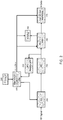
- FIG. 2 illustrates a flow diagram of one way, according to the present disclosure, an RF receiver including an RSSI (received signal strength indicator) measurement circuit 210 may allow for detection of second stronger signal transmission after beginning to detect a first weaker signal transmission.
- the RF signal to be received may be routed to both AGC (automatic gain control) circuitry 240 as well as RSSI circuitry 210.
- the RF signal may include a first signal.
- Such a signal is routed to the RSSI measurement circuitry 210, is measured for signal strength and such a measurement may be sent to the signal strength compare and logic circuitry 220 which assesses the level and sets an appropriate gain setting to the AGC circuitry 240 (which signal strength level may be indicated, for example, by a threshold difference of SNR/RSSI difference relative to the first signal).
- An appropriate level may be one that maximizes the signal without exceeding the dynamic range of the ADC (analog to digital converter) 250.
- a second signal larger in signal strength compared to the first signal, may begin transmission.
- the RSSI may now measure this larger signal strength including, at least, the signal strength of the first signal plus the signal strength of the second signal.
- This updated, larger measurement is sent to the signal strength compare and logic circuitry 220.
- the signal strength compare and logic circuitry 220 may compare the signal from the RSSI circuitry 210 to a previous level used to lock-in a gain setting in the AGC circuitry 240.
- the AGC 240 may be left unchanged and an abort/reset signal may be sent to the preamble detect circuitry 260, the ACQ flag circuitry 280, and the signal demod (demodulation) and decode circuitry 270. It may be noted that leaving the gain setting unchanged may allow for faster switching to the detected the second signal. This abort/reset may allow for the reception of the new larger signal in place of the first signal.
- the AGC may be readjusted to accommodate the larger signal without exceeding the dynamic range of the ADC 250. In such a situation, the abort/reset may also occur, as described previously.
- FIG. 3 is an example graph of packet error rate (PER) versus detected power, illustrating effects of noise/interference.
- Graph line 310 is an example of a transmitting signal's PER versus detected power level.
- Graph line 320 is an example illustrating how such a signal's PER may be affected when the environment, system circuitry, or other sources generate increased levels of noise/interference.
- Threshold line 340 indicates, in accordance with examples of the present disclosure as discussed above, an exemplary level of power at which switching between weaker and stronger signals may be appropriate for reducing (or rendering negligible) the PER, with vertical line 360 depicting the drop off of PER to approximately zero by using any further increased power level (e.g., the arrow indicated as 350, denotes the improvement of switching to detecting the stronger signal with the packet as described in connection with FIG. 2 ).
- the arrow indicated as 350 denotes the improvement of switching to detecting the stronger signal with the packet as described in connection with FIG. 2 .
- unrelated transmissions at close frequencies may result in increased noise levels above desired sensitivity levels. If the transmitting signal is weak, relative to the interfering noise, this may cause false detections and/or false acquisitions, as seen in graph line 330. Such interference may result in further degradations, these false detections may be mitigated by using steps/techniques described elsewhere in this disclosure.
- FIG. 4 is an RSSI versus signal strength graph illustrating an example benefiting from AGC adjustment.
- the example graph also illustrates two RSSI versus signal strength curves; antenna 1 curve is labeled 420 and antenna 2 curve is labeled 410.
- a first received signal 430 may be received, by antenna 2, with a signal strength of, for example, -90 dBm and an RSSI of -84 dBm with a first gain as adjusted by the AGC circuitry 240.
- the received signal will appear as shown in the line 460, which is the combination a first signal transmission and a second stronger signal transmission.
- Such a received combined signal may now have a signal strength of -60 dBm using a first gain as adjusted by the AGC circuitry 240.
- the RSSI level with the combined signals and the first gain level, may indicate that the ADC 250 is being saturated which may cause improper demodulation of the first signal and the second signal to fail. In such a situation it may be judicious to unlock the AGC to allow for readjustment of the gain.
- line 440 is the combination a first signal transmission and a second stronger signal transmission but with the gain adjusted down by 20 dB. Using such a lower gain may allow for the second, larger signal to be demodulated successfully.
- the RF receiver may include circuitry to assess the incoming signal and, based on the assessment, use circuitry to adjust AGC or signal-amplification. Steps of processing and assessing may be performed while at least the vehicle or a signal-transmit station, from which the first signal or the second signal is transmitted, is moving.
- Another specific example includes, a method wherein assessing that the second received signal is stronger than the first received signal includes or is associated with observing energy. Such an assessment may occur concurrently with processing a first received signal, using the RF receiver associated with the second received signal.
- assessing that the second received signal is stronger than the first received signal includes using an RSSI circuit.
- an RSSI circuit may operate concurrently with processing a first received signal by the RF receiver. This allows for observation of energy associated with the second received signal.
- the method and circuitry may adjust gain or signal-amplification circuitry including reducing a gain level provided by an automatic gain control (AGC) circuit.
- AGC automatic gain control
- Such a reduction in level may allow for continuing to process the second received signal and extract data therefrom in place of the first received signal.
- data extraction may be performed within an allotted transmission or reception time associated with the second signal thereby allowing for the acquisition of all payload data carried by the second signal.
- assessing that the second received signal is stronger than the first received signal may be an indication, in the RF receiver, that the second received signal is from a signal-transmit station which is closer to the RF receiver than another signal-transmit station from which the first signal is transmitted.
- the RF receiver may be part of a transceiver that communicates data wirelessly via CSMA or 802.11 communications protocols.
- the second received signal may be sufficiently stronger than the first received signal, as such it may cause the second received signal to interfere with data extracted from the first received signal.
- the step of detecting presence of a second received signal while the first received signal is being processed may include using a signal acquisition circuit in parallel with a circuit to decode or extract data from the first signal.
- the adjusting of gain or signal-amplification circuitry may be performed to obtain error-free or clipless processing of the second signal.
- the adjusting includes unfreezing of a gain level of the gain or signal-amplification circuitry and readjusting the gain or signal-amplification circuitry for receiving the second signal. This adjustment may be made to assure the received signal does not exceed the dynamic range of subsequent circuitry, such as an ADC. Further adjustment may include starting reception of a new packet, from the second signal, by implementing a reset of reception circuitry in the RF receiver. Such a reset may be triggered or timed relative to an indication of acquisition of the new packet.
- the above-noted adjustment for dynamic range may be implemented based on signal levels as measured by the RSSI circuitry. If the RSSI value indicates saturation, the signal may be exceeding the dynamic range for the subsequent circuitry.
- a further example embodiment according to the present disclosure is directed to an apparatus for use in a communication system in which a RF (radio frequency) receiver may be detecting and processing a first signal in an RF channel. During such detecting and processing of the first signal, a second received signal may be detected. In this example, the second received signal may be assessed, by receiver circuitry, as stronger than the first received signal. In response to the assessment of the second received signal being stronger than the first received signal, the RF receiver circuitry may adjust the gain or signal amplification circuitry for continuing to process the second, stronger, received signal in place of the first, weaker, received signal and thereby extracting data from the second signal.
- a RF radio frequency
- one or more modules are discrete logic circuits or programmable logic circuits configured and arranged for implementing these operations/activities, as may be carried out in the approaches shown in Figs. 1 and 2 .
- a programmable circuit is one or more computer circuits, including memory circuitry for storing and accessing a program to be executed as a set (or sets) of instructions (and/or to be used as configuration data to define how the programmable circuit is to perform), and an algorithm or process as described above is used by the programmable circuit to perform the related steps, functions, operations, activities, etc.
- the instructions can be configured for implementation in logic circuitry, with the instructions (whether characterized in the form of object code, firmware or software) stored in and accessible from a memory (circuit).
- the instructions whether characterized in the form of object code, firmware or software
- a memory circuit
- the adjectives "first” and “second” are not used to connote any description of the structure or to provide any substantive meaning.
Landscapes
- Engineering & Computer Science (AREA)
- Computer Networks & Wireless Communication (AREA)
- Signal Processing (AREA)
- Physics & Mathematics (AREA)
- Electromagnetism (AREA)
- Quality & Reliability (AREA)
- Circuits Of Receivers In General (AREA)
Abstract
Description
- Aspects of various embodiments are directed to an RF (radio frequency) receiver detecting transmitted data from a channel which may contain more than one transmitter and upon detection of signal strength, switching reception to the strongest detected signal.
- In most V2X application scenarios, reliable reception of 802.11p transmissions is a prerequisite that enables performance, reliability and safety of vehicular traffic. In congested urban scenarios, where hidden nodes prevent effective leveraging of the "talk before listen" (CSMA/CA) protocol, it becomes of paramount importance to receive packets pertaining to the safety neighborhood of the car (perimeter proportionally depends on environment, speed and type of the vehicle). Another problem are RF signal collisions which are related to amount of traffic on the channel. Due to the random-access policy for CSMA/CA and limited amount of Tx (transmission) Slots to choose from sometimes stations will draw the same random number and transmit at the same Tx Slot causing collisions. In both cases of hidden node and collisions a situation may occur when weak (far away) and strong (close by) packets coexist.
- These and other matters have presented challenges to successful detection of RF transmissions of strong and weak signals occurring at the same time on the same channel, for a variety of applications.
- Various example embodiments are directed to issues such as those addressed above and/or others which may become apparent from the following disclosure involving a method and apparatus in which an RF (radio frequency) receiver detects transmitted data from a channel which may contain more than one transmitter.
- In certain example embodiments, aspects of the present disclosure may involve a method for use in a communication system in which a RF receiver may be detecting and processing a first signal in an RF channel. Thereafter, a second received signal may be detected, with the second received signal being assessed, by receiver circuitry, as stronger than the first received signal. In response to the assessment of the second received signal being stronger than the first received signal, the RF receiver circuitry may adjust the gain or signal amplification circuitry for continuing to process the second, stronger, received signal in place of the first, weaker, received signal.
- In another example, the present disclosure is directed to a method where assessing that the second received signal is stronger than the first received signal includes or is associated with performing data packet acquisition from the second received signal in parallel with said processing a first received signal by the RF receiver. Further, steps may include aborting the step of processing the first received signal in response to the step of assessing that the second received signal is stronger than the first received signal.
- In more specific examples, an RF receiver may be located in a vehicle. The RF receiver may include circuitry to assess the incoming signal and, based on the assessment, use circuitry to adjust the AGC or signal-amplification. Steps of processing and assessing may be performed while at least the vehicle or a signal-transmit station, from which the first signal or the second signal is transmitted, is moving.
- In yet another specific example, the RF receiver may be part of a transceiver that communicates data wirelessly via CSMA or 802.11 communications protocols.
- The above discussion/summary is not intended to describe each embodiment or every implementation of the present disclosure. The figures and detailed description that follow also exemplify various embodiments.
- According to another aspect there is provided: an apparatus for communicating via a RF (radio frequency) channel, the apparatus comprising: an RF receiver to receive a first received signal carrying data in an RF channel; signal-detection circuitry, within the RF receiver, to detect presence of a second received signal in the RF channel while the first received signal is being processed; and signal-processing circuitry, also within the RF receiver, to assess that the second received signal is stronger than the first received signal and, in response, adjust gain or signal-amplification circuitry for continuing to process the second received signal and extract data therefrom in place of the first received signal.
- In embodiments, the signal-processing circuitry is further to cause processing the first received signal to cease in response to the step of assessing that the second received signal is stronger than the first received signal, and wherein the RF receiver is configured to be installed in a vehicle for operation by said circuitries while the vehicle is moving.
- In embodiments the signal-processing circuitry is to observe energy related to the first signal and/or second signal, concurrently while processing a first received signal by the RF receiver.
- In embodiments, the signal-processing circuitry is to use a signal-strength indication circuit concurrently with an operation of processing a first received signal, to observe energy associated with the second received signal, and further including an automotive gain control circuit to control signal gain and a signal-amplification circuitry to reduce a gain level provided by the automotive gain control circuit.
- In embodiments the signal-processing circuitry is to assess that the second received signal is stronger than the first received signal in association with an indication that the second received signal is from a signal-transmit station that is closer to the RF receiver than another signal-transmit station from which the first signal is transmitted.
- In embodiments, the RF receiver is part of a transceiver that is to communicate data wirelessly via CSMA or 802.11 communications protocols, and to switch to processing of the second received signal in response to an indication that the second received signal is stronger than the first received signal by a predetermined amount associated with an interference estimate.
- Various example embodiments may be more completely understood in consideration of the following detailed description in connection with the accompanying drawings, in which:
-
FIG. 1 is a system-level diagram illustrating an example of an RF receiver detecting a first RF transmitted signal and a stronger signal from a second RF transmitter, in accordance with the present disclosure; -
FIG. 2 is a flow diagram illustrating an example of an RF receiver including an abort/reset circuit to allow for detection of second stronger signal transmission after beginning to detect a first weaker signal transmission, in accordance with the present disclosure; -
FIG. 3 is a packet error rate (PER) versus detected power graph illustrating the effects of noise/interference, in accordance with the present disclosure; and -
FIG. 4 is an RSSI versus signal strength graph illustrating a first signal transmission and a stronger second signal transmission, in accordance with the present disclosure. - While various embodiments discussed herein are amenable to modifications and alternative forms, aspects thereof have been shown by way of example in the drawings and will be described in detail. It should be understood, however, that the intention is not to limit the disclosure to the particular embodiments described.
- Aspects of the present disclosure are believed to be applicable to a variety of different types of apparatuses, systems and methods involving a plurality of data transmitting systems sharing a frequency channel in which a second stronger transmission signals may be detected after beginning to process a first weaker transmission signal and, in which, it may be advantageous to switch to detecting the second stronger transmitted signal. While the following discussion refers to various protocols (e.g., 802.11, 802.11p, V2X, etc.) for certain communication systems, such discussion is for providing merely an exemplary context to help explain such aspects, and the present disclosure is not necessarily so limited.
- Accordingly, in the following description various specific details are set forth to describe specific examples presented herein. It should be apparent to one skilled in the art, however, that one or more other examples and/or variations of these examples may be practiced without all the specific details given below. In other instances, well known features have not been described in detail so as not to obscure the description of the examples herein. For ease of illustration, the same reference numerals may be used in different diagrams to refer to the same elements or additional instances of the same element. Also, although aspects and features may in some cases be described in individual figures, it will be appreciated that features from one figure or embodiment can be combined with features of another figure or embodiment even though the combination is not explicitly shown or explicitly described as a combination.
- In one example according to the present disclosure, certain embodiments are directed to a method for use in a communication system in which a RF (radio frequency) receiver may be detecting and processing a first signal in an RF channel. Thereafter, a second received signal may be detected, with the second received signal being assessed, by receiver circuitry, as stronger than the first received signal. In response to the assessment of the second received signal being stronger than the first received signal, the RF receiver circuitry may adjust the gain or signal amplification circuitry for continuing to process the second, stronger, received signal in place of the first, weaker, received signal.
- In another specific example according to the present disclosure, certain embodiments are directed to a method where assessing that the second received signal is stronger than the first received signal includes or is associated with performing data packet acquisition from the second received signal in parallel with said processing a first received signal by the RF receiver. Further, steps may include aborting the step of processing the first received signal in response to the step of assessing that the second received signal is stronger than the first received signal. During switching to the second, stronger, received signal there may be some latency to detect the switch condition, to abort the packet, adjust a new gain, and to start detecting the new packet. From lab measurements, this time may about 8/4[us] (in 10/20MHz mode). Although a large part of the signal preamble (large part of short training field STF) may be lost, a stronger packet may have good SNR (a quality signal to noise ratio, e.g., a range of 10 dB at highest gain down to a few or several dB) so it may be easy to acquire even if some samples are lost.
- Turning now to the drawings and relating to the above-disclosed aspects and embodiments,
FIG. 1 illustrates an example of anRF receiver 110 detecting a first receivedsignal 155 from afirst transmitter 150 and a second, stronger, receivedsignal 145 from asecond RF transmitter 140. In this example, theRF receiver 110 may be initially detecting thefirst signal 145 and the signalstrength detector circuit 115 may send a signal to the received signal gain adjust circuit 120 so as to not amplify the signal outside of the dynamic range of thechannel receiver circuitry 125. Such a signal, from the signal strength detector, may lock-in a gain setting and not allow further adjustments while receiving the first receivedsignal 155. A second, stronger, receivedsignal 145 may then also be received. In response to thesignal strength detector 115 assessing the new signal strength as being larger than the previous signal strength, theRF receiver circuitry 110 may readjust the received signal gain adjust circuitry 120 so as to not amplify the new signal outside of the dynamic range of thechannel receiver circuitry 125. (Measured signal strength of the new signal may now include, at least, the first receivedsignal 155 plus the second receivedsignal 145.) Thechannel receiver circuitry 125 may now receive the second receivedsignal 145 in place of the first receivedsignal 155. -
FIG. 2 illustrates a flow diagram of one way, according to the present disclosure, an RF receiver including an RSSI (received signal strength indicator)measurement circuit 210 may allow for detection of second stronger signal transmission after beginning to detect a first weaker signal transmission. In such examples the RF signal to be received may be routed to both AGC (automatic gain control)circuitry 240 as well asRSSI circuitry 210. Upon initial operation the RF signal may include a first signal. Such a signal is routed to theRSSI measurement circuitry 210, is measured for signal strength and such a measurement may be sent to the signal strength compare andlogic circuitry 220 which assesses the level and sets an appropriate gain setting to the AGC circuitry 240 (which signal strength level may be indicated, for example, by a threshold difference of SNR/RSSI difference relative to the first signal). An appropriate level may be one that maximizes the signal without exceeding the dynamic range of the ADC (analog to digital converter) 250. - Continuing with the above discussion, during the ongoing operation of receiving RF signals routed to the
RSSI measurement circuitry 210, a second signal, larger in signal strength compared to the first signal, may begin transmission. The RSSI may now measure this larger signal strength including, at least, the signal strength of the first signal plus the signal strength of the second signal. This updated, larger measurement is sent to the signal strength compare andlogic circuitry 220. The signal strength compare andlogic circuitry 220 may compare the signal from theRSSI circuitry 210 to a previous level used to lock-in a gain setting in theAGC circuitry 240. If the updated larger signal strength minus the previous locked-in signal strength is less than or equal to athreshold value 230, theAGC 240 may be left unchanged and an abort/reset signal may be sent to the preamble detectcircuitry 260, theACQ flag circuitry 280, and the signal demod (demodulation) anddecode circuitry 270. It may be noted that leaving the gain setting unchanged may allow for faster switching to the detected the second signal. This abort/reset may allow for the reception of the new larger signal in place of the first signal. If the updated larger signal strength minus the previous locked-in signal strength is greater than thethreshold value 230, or theRSSI measurement 210 indicates RSSI saturation, the AGC may be readjusted to accommodate the larger signal without exceeding the dynamic range of theADC 250. In such a situation, the abort/reset may also occur, as described previously. -
FIG. 3 is an example graph of packet error rate (PER) versus detected power, illustrating effects of noise/interference.Graph line 310 is an example of a transmitting signal's PER versus detected power level.Graph line 320 is an example illustrating how such a signal's PER may be affected when the environment, system circuitry, or other sources generate increased levels of noise/interference.Threshold line 340 indicates, in accordance with examples of the present disclosure as discussed above, an exemplary level of power at which switching between weaker and stronger signals may be appropriate for reducing (or rendering negligible) the PER, withvertical line 360 depicting the drop off of PER to approximately zero by using any further increased power level (e.g., the arrow indicated as 350, denotes the improvement of switching to detecting the stronger signal with the packet as described in connection withFIG. 2 ). It may be further appreciated that unrelated transmissions at close frequencies (neighboring channels) may result in increased noise levels above desired sensitivity levels. If the transmitting signal is weak, relative to the interfering noise, this may cause false detections and/or false acquisitions, as seen ingraph line 330. Such interference may result in further degradations, these false detections may be mitigated by using steps/techniques described elsewhere in this disclosure. -
FIG. 4 is an RSSI versus signal strength graph illustrating an example benefiting from AGC adjustment. The example graph also illustrates two RSSI versus signal strength curves; antenna 1 curve is labeled 420 andantenna 2 curve is labeled 410. In this example a first receivedsignal 430 may be received, byantenna 2, with a signal strength of, for example, -90 dBm and an RSSI of -84 dBm with a first gain as adjusted by theAGC circuitry 240. Continuing with this example; if a second, stronger, signal subsequently begins transmission, the received signal will appear as shown in theline 460, which is the combination a first signal transmission and a second stronger signal transmission. Such a received combined signal may now have a signal strength of -60 dBm using a first gain as adjusted by theAGC circuitry 240. The RSSI level, with the combined signals and the first gain level, may indicate that theADC 250 is being saturated which may cause improper demodulation of the first signal and the second signal to fail. In such a situation it may be judicious to unlock the AGC to allow for readjustment of the gain. This is illustrated byline 440, which is the combination a first signal transmission and a second stronger signal transmission but with the gain adjusted down by 20 dB. Using such a lower gain may allow for the second, larger signal to be demodulated successfully. - One specific example includes using an RF receiver in a vehicle. The RF receiver may include circuitry to assess the incoming signal and, based on the assessment, use circuitry to adjust AGC or signal-amplification. Steps of processing and assessing may be performed while at least the vehicle or a signal-transmit station, from which the first signal or the second signal is transmitted, is moving.
- Another specific example includes, a method wherein assessing that the second received signal is stronger than the first received signal includes or is associated with observing energy. Such an assessment may occur concurrently with processing a first received signal, using the RF receiver associated with the second received signal.
- In yet another specific example of the instant disclosure, wherein assessing that the second received signal is stronger than the first received signal includes using an RSSI circuit. Such an RSSI circuit may operate concurrently with processing a first received signal by the RF receiver. This allows for observation of energy associated with the second received signal.
- In certain more-specific examples, the method and circuitry may adjust gain or signal-amplification circuitry including reducing a gain level provided by an automatic gain control (AGC) circuit. Such a reduction in level may allow for continuing to process the second received signal and extract data therefrom in place of the first received signal. Such data extraction may be performed within an allotted transmission or reception time associated with the second signal thereby allowing for the acquisition of all payload data carried by the second signal.
- In certain other examples, assessing that the second received signal is stronger than the first received signal may be an indication, in the RF receiver, that the second received signal is from a signal-transmit station which is closer to the RF receiver than another signal-transmit station from which the first signal is transmitted.
- In another example embodiment, the RF receiver may be part of a transceiver that communicates data wirelessly via CSMA or 802.11 communications protocols.
- In certain specific examples, the second received signal may be sufficiently stronger than the first received signal, as such it may cause the second received signal to interfere with data extracted from the first received signal.
- In yet another example, the step of detecting presence of a second received signal while the first received signal is being processed may include using a signal acquisition circuit in parallel with a circuit to decode or extract data from the first signal.
- In yet another example embodiment of the instant disclosure, the adjusting of gain or signal-amplification circuitry, using for example an AGC circuit, may be performed to obtain error-free or clipless processing of the second signal.
- In another example, the adjusting includes unfreezing of a gain level of the gain or signal-amplification circuitry and readjusting the gain or signal-amplification circuitry for receiving the second signal. This adjustment may be made to assure the received signal does not exceed the dynamic range of subsequent circuitry, such as an ADC. Further adjustment may include starting reception of a new packet, from the second signal, by implementing a reset of reception circuitry in the RF receiver. Such a reset may be triggered or timed relative to an indication of acquisition of the new packet.
- The above-noted adjustment for dynamic range may be implemented based on signal levels as measured by the RSSI circuitry. If the RSSI value indicates saturation, the signal may be exceeding the dynamic range for the subsequent circuitry.
- A further example embodiment according to the present disclosure is directed to an apparatus for use in a communication system in which a RF (radio frequency) receiver may be detecting and processing a first signal in an RF channel. During such detecting and processing of the first signal, a second received signal may be detected. In this example, the second received signal may be assessed, by receiver circuitry, as stronger than the first received signal. In response to the assessment of the second received signal being stronger than the first received signal, the RF receiver circuitry may adjust the gain or signal amplification circuitry for continuing to process the second, stronger, received signal in place of the first, weaker, received signal and thereby extracting data from the second signal.
- The skilled artisan would recognize that various terminology as used in the Specification (including claims) connote a plain meaning in the art unless otherwise indicated. As examples, the Specification describes and/or illustrates aspects useful for implementing the claimed disclosure by way of various circuits or circuitry which may be illustrated as or using terms such as blocks, modules, device, system, unit, controller, and/or other circuit-type depictions (e.g.,
reference numerals 115 and 120 ofFIG. 1 depict a block/module as described herein). Such circuits or circuitry are used together with other elements to exemplify how certain embodiments may be carried out in the form or structures, steps, functions, operations, activities, etc. For example, in certain of the above-discussed embodiments, one or more modules are discrete logic circuits or programmable logic circuits configured and arranged for implementing these operations/activities, as may be carried out in the approaches shown inFigs. 1 and2 . In certain embodiments, such a programmable circuit is one or more computer circuits, including memory circuitry for storing and accessing a program to be executed as a set (or sets) of instructions (and/or to be used as configuration data to define how the programmable circuit is to perform), and an algorithm or process as described above is used by the programmable circuit to perform the related steps, functions, operations, activities, etc. Depending on the application, the instructions (and/or configuration data) can be configured for implementation in logic circuitry, with the instructions (whether characterized in the form of object code, firmware or software) stored in and accessible from a memory (circuit). As another example, where the Specification may make reference to a "first [type of structure]", a "second [type of structure]", etc., where the [type of structure] might be replaced with terms such as ["circuit", "circuitry" and others], the adjectives "first" and "second" are not used to connote any description of the structure or to provide any substantive meaning. - Based upon the above discussion and illustrations, those skilled in the art will readily recognize that various modifications and changes may be made to the various embodiments without strictly following the exemplary embodiments and applications illustrated and described herein. For example, methods as exemplified in the Figures may involve steps carried out in various orders, with one or more aspects of the embodiments herein retained, or may involve fewer or more steps. For instance, as shown in
FIG. 2 . Such modifications do not depart from the true spirit and scope of various aspects of the disclosure, including aspects set forth in the claims
Claims (15)
- A method for communicating over a channel, the method comprising:processing, in an radio frequency, RF, receiver, a first received signal carrying data in an RF channel;via the RF receiver, detecting presence of a second received signal in the RF channel while the first received signal is being processed; andassessing that the second received signal is stronger than the first received signal and, in response, adjusting gain or signal-amplification circuitry for continuing to process the second received signal and extract data therefrom in place of the first received signal.
- The method of claim 1, wherein assessing that the second received signal is stronger than the first received signal includes or is associated with performing data packet acquisition from the second received signal in parallel with said processing a first received signal by the RF receiver, and further including aborting the step of processing the first received signal in response to the step of assessing that the second received signal is stronger than the first received signal.
- The method of claim 1 or 2, further including using the RF receiver in a vehicle and wherein the steps of processing and assessing are performed while at least one of the following is moving: the vehicle; and a signal-transmit station from which the first signal or the second signal is transmitted.
- The method of any preceding claim, wherein assessing that the second received signal is stronger than the first received signal at least of one of: includes or is associated with observing energy, concurrently with said processing a first received signal by the RF receiver, associated with the second received signa; includes using an receiver-signal-strength-indication, RSSI, circuit, concurrently with said processing a first received signal by the RF receiver, to observe energy associated with the second received signal; and includes or is associated with an indication in the RF receiver that the second received signal is from a signal-transmit station which is closer to the RF receiver than another signal-transmit station from which the first signal is transmitted
- The method of any preceding claim, wherein adjusting gain or signal-amplification circuitry includes reducing a gain level provided by an automotive gain control, AGC, circuit, and wherein the step of continuing to process the second received signal and extract data therefrom in place of the first received signal is performed within an allotted transmission or reception time associated with the second signal to acquire all payload data carried by the second signal.
- The method of any preceding claim, wherein the RF receiver is part of a transceiver that communicates data wirelessly via CSMA or 802.11 communications protocols.
- The method of any preceding claim, wherein the second received signal is sufficiently stronger than the first received signal to cause the second received signal to interfere with data extracted from the first received signal.
- The method of claim 7, wherein the second received signal is stronger than the first received signal, as indicated by a threshold or difference in signal-to-noise, SNR ratio and/or received signal strength indication, to cause the second received signal to interfere with data extracted from the first received signal.
- The method of any preceding claim, wherein the step of detecting presence of a second received signal while the first received signal is being processed includes using a signal acquisition circuit in parallel with a circuit to decode or extract data from the first signal.
- The method of any preceding claim, wherein the adjusting is performed to obtain error-free or clipless processing of the second signal.
- The method of any preceding claim, wherein the adjusting includes unfreezing of a gain level of the gain or signal-amplification circuitry and readjusting the gain or signal-amplification circuitry for receiving the second signal, and further includes starting reception of a new packet, from the second signal, based on a reset of reception circuitry in the RF receiver and which reset is triggered or timed relative to an indication of acquisition of the new packet.
- The method of any preceding claim, wherein the RF receiver is part of a transceiver that is to communicate data wirelessly via a 802.11 communications protocol, and wherein the RF receiver switches to processing of the second received signal in response to an indication that the second received signal is stronger than the first received signal by a predetermined amount associated with an interference estimate.
- An apparatus for communicating via a radio frequency, RF, channel, the apparatus comprising:an RF receiver to receive a first received signal carrying data in an RF channel;signal-detection circuitry, within the RF receiver, to detect presence of a second received signal in the RF channel while the first received signal is being processed; andsignal-processing circuitry, also within the RF receiver, to assess that the second received signal is stronger than the first received signal and, in response, adjust gain or signal-amplification circuitry for continuing to process the second received signal and extract data therefrom in place of the first received signal.
- The apparatus of claim 13, wherein the signal-processing circuitry is further to cause processing the first received signal to cease in response to the step of assessing that the second received signal is stronger than the first received signal, and wherein the RF receiver is configured to be installed in a vehicle for operation by said circuitries while the vehicle is moving.
- The apparatus of claim 13 or 14, wherein the signal-processing circuitry is to observe energy related to the first signal and/or second signal, concurrently while processing a first received signal by the RF receiver.
Applications Claiming Priority (1)
| Application Number | Priority Date | Filing Date | Title |
|---|---|---|---|
| US16/908,930 US11671924B2 (en) | 2020-06-23 | 2020-06-23 | Receiving strongest signal in an RF receiver |
Publications (1)
| Publication Number | Publication Date |
|---|---|
| EP3930202A1 true EP3930202A1 (en) | 2021-12-29 |
Family
ID=76180852
Family Applications (1)
| Application Number | Title | Priority Date | Filing Date |
|---|---|---|---|
| EP21176066.5A Pending EP3930202A1 (en) | 2020-06-23 | 2021-05-26 | Receiving strongest signal in an rf receiver |
Country Status (3)
| Country | Link |
|---|---|
| US (1) | US11671924B2 (en) |
| EP (1) | EP3930202A1 (en) |
| CN (1) | CN113839726A (en) |
Families Citing this family (1)
| Publication number | Priority date | Publication date | Assignee | Title |
|---|---|---|---|---|
| US20230012962A1 (en) * | 2021-07-13 | 2023-01-19 | Beta Air, Llc | Methods and systems for a fly by view in an electric aircraft |
Citations (4)
| Publication number | Priority date | Publication date | Assignee | Title |
|---|---|---|---|---|
| US20050100119A1 (en) * | 2003-11-07 | 2005-05-12 | Atheros Communications, Inc. | Adaptive interference immunity control |
| US20070264950A1 (en) * | 2003-02-21 | 2007-11-15 | Atheros Communications, Inc. | Method And Apparatus For Selective Disregard Of Co-Channel Transmissions On A Medium |
| US20130083676A1 (en) * | 2011-09-30 | 2013-04-04 | Cisco Technology, Inc. | Enhanced Stomp-and-Restart with Interference Suppression |
| US20170264356A1 (en) * | 2016-03-11 | 2017-09-14 | Qualcomm Incorporated | Techniques for detecting a candidate information signal of unknown signal strength using receivers set to different fixed gain states |
Family Cites Families (6)
| Publication number | Priority date | Publication date | Assignee | Title |
|---|---|---|---|---|
| US8391192B2 (en) | 2007-05-14 | 2013-03-05 | Qualcomm Incorporated | Carrier switching in a multi-carrier wireless communication network |
| US20120115416A1 (en) * | 2010-11-05 | 2012-05-10 | Tevfik Yucek | Wireless device limiting gain of a shared gain element between different wireless protocols |
| CN102568043B (en) * | 2010-12-23 | 2014-01-08 | 博通集成电路(上海)有限公司 | Method and vehicle-mounted unit for electronic tolling system |
| US9992724B2 (en) * | 2016-06-01 | 2018-06-05 | General Motors Llc | Cell selection and reselection using a vehicle antenna |
| US10652059B2 (en) * | 2018-06-19 | 2020-05-12 | CoreTigo, Ltd. | Mission critical wireless communication link master gateway |
| US11134449B2 (en) * | 2019-06-11 | 2021-09-28 | Qualcomm Incorporated | Controlling transmission power across basic service sets (BSSs) |
-
2020
- 2020-06-23 US US16/908,930 patent/US11671924B2/en active Active
-
2021
- 2021-05-26 EP EP21176066.5A patent/EP3930202A1/en active Pending
- 2021-06-22 CN CN202110694821.XA patent/CN113839726A/en active Pending
Patent Citations (4)
| Publication number | Priority date | Publication date | Assignee | Title |
|---|---|---|---|---|
| US20070264950A1 (en) * | 2003-02-21 | 2007-11-15 | Atheros Communications, Inc. | Method And Apparatus For Selective Disregard Of Co-Channel Transmissions On A Medium |
| US20050100119A1 (en) * | 2003-11-07 | 2005-05-12 | Atheros Communications, Inc. | Adaptive interference immunity control |
| US20130083676A1 (en) * | 2011-09-30 | 2013-04-04 | Cisco Technology, Inc. | Enhanced Stomp-and-Restart with Interference Suppression |
| US20170264356A1 (en) * | 2016-03-11 | 2017-09-14 | Qualcomm Incorporated | Techniques for detecting a candidate information signal of unknown signal strength using receivers set to different fixed gain states |
Non-Patent Citations (1)
| Title |
|---|
| PUNAL OSCAR ET AL: "Experimental Characterization and Modeling of RF Jamming Attacks on VANETs", IEEE TRANSACTIONS ON VEHICULAR TECHNOLOGY, IEEE, USA, vol. 64, no. 2, 1 February 2015 (2015-02-01), pages 524 - 540, XP011572797, ISSN: 0018-9545, [retrieved on 20150209], DOI: 10.1109/TVT.2014.2325831 * |
Also Published As
| Publication number | Publication date |
|---|---|
| US20210400597A1 (en) | 2021-12-23 |
| US11671924B2 (en) | 2023-06-06 |
| CN113839726A (en) | 2021-12-24 |
Similar Documents
| Publication | Publication Date | Title |
|---|---|---|
| US7372890B2 (en) | Methods and systems for detecting and mitigating interference for a wireless device | |
| Punal et al. | Experimental characterization and modeling of RF jamming attacks on VANETs | |
| EP1595344B1 (en) | Method and apparatus for selective disregard of co-channel transmissions on a medium | |
| US8254928B2 (en) | Communication control apparatus and method | |
| US8031808B2 (en) | Multiple-branch wireless receiver | |
| US20130260705A1 (en) | Systems and methods for adjusting system tests based on detected interference | |
| US20060209746A1 (en) | Controller and transmission and reception method for radio communications in a transceiver for radio communications | |
| US9544862B2 (en) | Method and device for performing automatic gain control | |
| US20100246556A1 (en) | Communication method and apparatus | |
| US11671924B2 (en) | Receiving strongest signal in an RF receiver | |
| US7263363B2 (en) | Method for mitigating intermodulation interference using channel power estimation and attenuation in a two-way radio communications system | |
| US8923183B2 (en) | Terminal apparatus for transmitting or receiving a signal including predetermined information | |
| TWI660643B (en) | Gain adjustment method for wireless communication | |
| US20210099243A1 (en) | Vehicle-to-x communication system | |
| CN116193498B (en) | Channel busy and idle state evaluation method and device and electronic equipment | |
| JP5005297B2 (en) | Wireless LAN device | |
| US20180263036A1 (en) | Communicating device and associated method applying multiple packet detectors | |
| US12495367B2 (en) | System, method and apparatus for adaptively controlling transmit power based on energy detection | |
| CN108882351B (en) | Gain adjustment method for wireless communication | |
| JP3996877B2 (en) | Wireless communication device | |
| JP4633037B2 (en) | Transceiver | |
| Norris et al. | Methods of Detection of Bandlimited Signals on UHF MILSATCOM Downlinks | |
| JPH04373341A (en) | Signal collision detecting system | |
| JPH04373343A (en) | Information processing terminal for radio communication network | |
| US7434143B2 (en) | Method and arrangement for detecting a collision in a communication network |
Legal Events
| Date | Code | Title | Description |
|---|---|---|---|
| PUAI | Public reference made under article 153(3) epc to a published international application that has entered the european phase |
Free format text: ORIGINAL CODE: 0009012 |
|
| STAA | Information on the status of an ep patent application or granted ep patent |
Free format text: STATUS: THE APPLICATION HAS BEEN PUBLISHED |
|
| AK | Designated contracting states |
Kind code of ref document: A1 Designated state(s): AL AT BE BG CH CY CZ DE DK EE ES FI FR GB GR HR HU IE IS IT LI LT LU LV MC MK MT NL NO PL PT RO RS SE SI SK SM TR |
|
| B565 | Issuance of search results under rule 164(2) epc |
Effective date: 20211122 |
|
| STAA | Information on the status of an ep patent application or granted ep patent |
Free format text: STATUS: REQUEST FOR EXAMINATION WAS MADE |
|
| 17P | Request for examination filed |
Effective date: 20220629 |
|
| RBV | Designated contracting states (corrected) |
Designated state(s): AL AT BE BG CH CY CZ DE DK EE ES FI FR GB GR HR HU IE IS IT LI LT LU LV MC MK MT NL NO PL PT RO RS SE SI SK SM TR |
|
| STAA | Information on the status of an ep patent application or granted ep patent |
Free format text: STATUS: EXAMINATION IS IN PROGRESS |
|
| 17Q | First examination report despatched |
Effective date: 20240404 |