EP3930183A1 - Interface circuit of motor driving apparatus - Google Patents
Interface circuit of motor driving apparatus Download PDFInfo
- Publication number
- EP3930183A1 EP3930183A1 EP19916289.2A EP19916289A EP3930183A1 EP 3930183 A1 EP3930183 A1 EP 3930183A1 EP 19916289 A EP19916289 A EP 19916289A EP 3930183 A1 EP3930183 A1 EP 3930183A1
- Authority
- EP
- European Patent Office
- Prior art keywords
- unit
- mcu
- interface circuit
- additional device
- power circuit
- Prior art date
- Legal status (The legal status is an assumption and is not a legal conclusion. Google has not performed a legal analysis and makes no representation as to the accuracy of the status listed.)
- Granted
Links
Images

Classifications
-
- H—ELECTRICITY
- H02—GENERATION; CONVERSION OR DISTRIBUTION OF ELECTRIC POWER
- H02P—CONTROL OR REGULATION OF ELECTRIC MOTORS, ELECTRIC GENERATORS OR DYNAMO-ELECTRIC CONVERTERS; CONTROLLING TRANSFORMERS, REACTORS OR CHOKE COILS
- H02P31/00—Arrangements for regulating or controlling electric motors not provided for in groups H02P1/00 - H02P5/00, H02P7/00 or H02P21/00 - H02P29/00
-
- H—ELECTRICITY
- H02—GENERATION; CONVERSION OR DISTRIBUTION OF ELECTRIC POWER
- H02P—CONTROL OR REGULATION OF ELECTRIC MOTORS, ELECTRIC GENERATORS OR DYNAMO-ELECTRIC CONVERTERS; CONTROLLING TRANSFORMERS, REACTORS OR CHOKE COILS
- H02P25/00—Arrangements or methods for the control of AC motors characterised by the kind of AC motor or by structural details
- H02P25/16—Arrangements or methods for the control of AC motors characterised by the kind of AC motor or by structural details characterised by the circuit arrangement or by the kind of wiring
-
- H—ELECTRICITY
- H02—GENERATION; CONVERSION OR DISTRIBUTION OF ELECTRIC POWER
- H02P—CONTROL OR REGULATION OF ELECTRIC MOTORS, ELECTRIC GENERATORS OR DYNAMO-ELECTRIC CONVERTERS; CONTROLLING TRANSFORMERS, REACTORS OR CHOKE COILS
- H02P27/00—Arrangements or methods for the control of AC motors characterised by the kind of supply voltage
- H02P27/04—Arrangements or methods for the control of AC motors characterised by the kind of supply voltage using variable-frequency supply voltage, e.g. inverter or converter supply voltage
- H02P27/06—Arrangements or methods for the control of AC motors characterised by the kind of supply voltage using variable-frequency supply voltage, e.g. inverter or converter supply voltage using DC to AC converters or inverters
-
- H—ELECTRICITY
- H02—GENERATION; CONVERSION OR DISTRIBUTION OF ELECTRIC POWER
- H02P—CONTROL OR REGULATION OF ELECTRIC MOTORS, ELECTRIC GENERATORS OR DYNAMO-ELECTRIC CONVERTERS; CONTROLLING TRANSFORMERS, REACTORS OR CHOKE COILS
- H02P29/00—Arrangements for regulating or controlling electric motors, appropriate for both AC and DC motors
- H02P29/60—Controlling or determining the temperature of the motor or of the drive
-
- H—ELECTRICITY
- H05—ELECTRIC TECHNIQUES NOT OTHERWISE PROVIDED FOR
- H05K—PRINTED CIRCUITS; CASINGS OR CONSTRUCTIONAL DETAILS OF ELECTRIC APPARATUS; MANUFACTURE OF ASSEMBLAGES OF ELECTRICAL COMPONENTS
- H05K7/00—Constructional details common to different types of electric apparatus
- H05K7/20—Modifications to facilitate cooling, ventilating, or heating
- H05K7/2089—Modifications to facilitate cooling, ventilating, or heating for power electronics, e.g. for inverters for controlling motor
- H05K7/20909—Forced ventilation, e.g. on heat dissipaters coupled to components
-
- H—ELECTRICITY
- H02—GENERATION; CONVERSION OR DISTRIBUTION OF ELECTRIC POWER
- H02P—CONTROL OR REGULATION OF ELECTRIC MOTORS, ELECTRIC GENERATORS OR DYNAMO-ELECTRIC CONVERTERS; CONTROLLING TRANSFORMERS, REACTORS OR CHOKE COILS
- H02P3/00—Arrangements for stopping or slowing electric motors, generators, or dynamo-electric converters
- H02P3/06—Arrangements for stopping or slowing electric motors, generators, or dynamo-electric converters for stopping or slowing an individual dynamo-electric motor or dynamo-electric converter
- H02P3/18—Arrangements for stopping or slowing electric motors, generators, or dynamo-electric converters for stopping or slowing an individual dynamo-electric motor or dynamo-electric converter for stopping or slowing an AC motor
Definitions
- the present invention relates to an interface circuit of a motor driving apparatus, and more specifically to an interface circuit of a motor driving apparatus capable of simplifying the structure and reducing costs.
- a motor driving apparatus includes a power circuit unit for providing driving power to a motor and a control panel for detecting and displaying the operation state of the power circuit unit, and controlling the power circuit unit to comply with a control command which is input through a user interface.
- the Underwriters Laboratories (UL) standards stipulate the insulation grade for the user interface and power circuit part of an inverter, and the products that meet these standards are being produced.
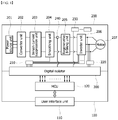
- FIG. 1 is an interface circuit diagram of a conventional motor driving apparatus.
- the interface circuit of a conventional motor driving apparatus is configured by including a power circuit unit 200, a control panel unit 100 and a digital isolator 300 that performs digital insulation on all signals transmitted between the power circuit unit 200 and the control panel unit 100.
- the power circuit unit 200 includes circuits for driving a motor 207, for example, a power supply unit 201, a converter unit 202, an inrush current suppression unit 203, a smoothing unit 204, a regenerative braking unit 205, and an inverter unit 206.
- a motor 207 for example, a power supply unit 201, a converter unit 202, an inrush current suppression unit 203, a smoothing unit 204, a regenerative braking unit 205, and an inverter unit 206.
- a gate driving unit 210 and various sensors 220 for driving individual gate elements of an inverter unit 206, and also includes relays 240 and additional device units 230.
- the control panel unit 100 is configured by including a user interface unit 110 that the user directly contacts, and an MCU 120 that controls the power circuit unit 200 according to the input of the user interface unit 110 and detects the operation state of the power circuit unit 200 to display the same on the user interface unit 110.
- each of the converter unit 202, the inrush current suppression unit 203, the smoothing unit 204, the regenerative braking unit 205 and the inverter unit 206 of the power circuit unit 200 are generally known, and thus, detailed descriptions thereof will be omitted.
- the power circuit unit 200 includes a gate driving unit 210 as a basic circuit configuration for driving the motor 207, and may drive a plurality of gate elements provided in the inverter unit 206.
- additional device units 230 that operate under the control of the MCU 120 are included.
- the additional device units 230 may include a plurality of cooling fans, an air circulation device including a blower, environmental monitoring devices such as a temperature sensor, a humidity sensor and the like.
- various functional blocks of the power circuit unit 200 operate under the control of the control panel unit 100.
- the control panel unit 100 includes various sensors to determine the operation state of the power circuit unit 200 and display the same on the user interface unit 110.
- Insulation is required for the signals of various sensors, and the digital isolator 300 is used for insulation, which is expensive and requires a relatively large installation area.
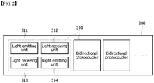
- FIG. 2 is a simple block configurational diagram of a digital isolator.
- the digital isolator 300 includes a plurality of photocouplers, and in particular, for bidirectional insulation between the power circuit unit 200 and the MCU 120, since it is necessary to use a bidirectional photocoupler 310 having a pair of light emitting units 311, 314 and light receiving units 312, 313 on one side, respectively, there has been a problem in that the cost and installation area increase.
- the technical problem to be solved by the present invention is to provide an interface circuit of a motor driving apparatus capable of reducing the manufacturing cost and improving the tolerance of installation space.
- the present invention for solving the above technical problem provides an interface circuit of a motor driving apparatus, the interface circuit including a power circuit unit for controlling driving of a motor, and a control panel unit which controls the power circuit unit and provides a user interface, wherein the power circuit unit further includes a second MCU which controls a relay and an additional device unit and detects an operation state of the additional device unit, and the second MCU can communicate with a first MCU of the control panel unit via a communication line.
- it may further include a digital isolator provided in the first MCU and the power circuit unit to insulate a transmission/reception signal between gate driving units controlling the gate elements of an inverter unit.
- the digital isolator may insulate a signal of a sensor unit detecting an operation state of the motor and provide the same to the first MCU.
- the second MCU may be configured to turn on/off the gate elements of an inverter unit in accordance with a control signal of the first MCU.
- the additional device unit may include a cooling fan, a blower or an environmental sensor.
- the second MCU may communicate with the first MCU according to the priority.
- the second MCU may communicate with the first MCU only when there is a change in the detection result of the additional device unit.
- the second MCU may block the relay in accordance with the detection result of the additional device unit.
- the present invention can reduce costs by limiting the use of a digital isolator, and it has an effect of securing a tolerance of installation space.
- Control panel unit 11 User interface unit 12: First MCU 13: Communication line 20: Power circuit unit 30: Digital isolator 40: Relay 50: Additional device unit 60: Second MCU
- 'first' and 'second' may be used to describe various components, but the above components should not be limited by the above terms. The above terms may only be used for the purpose of distinguishing one component from another. For example, without departing from the scope of the present invention, a 'first component' may be referred to as a 'second component', and similarly, a 'second component' may also be referred to as a 'first component.'
- the singular expression includes the plural expression unless the context clearly dictates otherwise. Unless defined otherwise, terms used in the exemplary embodiments of the present invention may be interpreted as meanings commonly known to those of ordinary skill in the art.
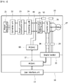
- FIG. 3 is an interface circuit diagram of a motor driving apparatus according to an exemplary embodiment of the present invention.
- the interface circuit of a motor driving apparatus includes a power circuit unit 20 for driving a motor 27 and a control panel unit 10 for controlling the power circuit unit 20, and also includes a second MCU 60 that communicates with a first micro controller unit (MCU) 12 of the control panel unit 10 in the power circuit unit 20 to monitor and control the state of a relay 40 and an additional device unit 50.
- MCU micro controller unit
- the digital isolator 30 insulates signals mutually transmitted between the power circuit unit 20 and the control panel unit 10 without passing through the second MCU 60.
- the power circuit unit 20 may include circuits for driving the motor 27, for example, a power supply unit 21, a converter unit 22, an inrush current suppression unit 23, a smoothing unit 24, a regenerative braking unit 25, and an inverter unit 26.
- circuits for driving the motor 27 listed above are an example, and the circuit configuration may be changed as needed.
- the power circuit unit 20 includes a gate driving unit 28 and a sensor unit 29, and the gate driving unit 28 controls gate elements provided in the inverter unit 26, and the sensor unit 29 detects the driving current of the motor 27 and provides the operation state of the motor 27.
- the control panel unit 10 displays such that the user may recognize the operation state of the power circuit unit 20 including the operating state of the motor 27, and it may control a user interface unit 11 that can receive the user's control command and a gate driving unit 28 via the digital isolator 30, and include a first MCU 12 for receiving the signal of a sensor unit 29 and a communication line 13 for data transmission between the first MCU 12 and the second MCU 60 of the power circuit unit 20.
- the first MCU 12 outputs various control signals according to the settings.
- the control signal for controlling the relay 40 and the control signal for controlling the additional device unit 50 are transmitted to the second MCU 60 of the power circuit unit 20 via the communication line 13.
- the communication line 13 is determined according to the communication method between the first MCU 12 and the second MCU 60, and a serial or parallel communication line may be used.
- the second MCU 60 receiving the control signal of the first MCU 12 controls and drives the relay 40 and the additional device units 50.
- control signal of the first MCU 12 for controlling the inverter unit 26 is provided to the gate driving unit 28 via the digital isolator 30, and the gate driving unit 28 drives the motor 27 by controlling the control state of the gate elements provided in the inverter unit 26.
- the driving control of the motor 27 may be a rotation direction and speed.
- Such an operation state of the motor 27 is detected by the sensor unit 29.
- the operation state detected by the sensor unit 29 is received by the first MCU 12 via the digital isolator 30, and the first MCU 12 displays the operation state of the motor 27 on the user interface unit 11 for the user to recognize the same.
- the digital isolator 30 includes photocouplers, and since insulation is performed only on limited signals that are transmission/reception signals between the sensor unit 29, which detects the operation of the gate driving unit 28 and the motor 27, and the first MCU 12, the number of photocouplers may be reduced, and the cost and volume may be reduced by reducing the quantity of photocouplers, which have a large price difference depending on the insulation level.
- the state of the additional device unit 50 is detected by the second MCU 60.
- the additional device unit 50 may be an air circulation device such as a cooling fan, a blower or the like, and in this case, the rotation speed of the cooling fan and the blower is detected by the second MCU 60.
- the detected information is transmitted to the first MCU 12 via the communication line 13, and the first MCU 12 may display the rotation speed of the cooling fan and the blower on the user interface unit 11.
- the present invention is characterized in that control and information detection are possible in a communication method that does not require insulation from the first MCU 12 by further including the second MCU 60, and the amount of data communications via the communication line 13 may be increased.
- the second MCU 60 may be set to transmit information to the first MCU 12 via the communication line 13 only when there is a change in the state of the relay 40 or the additional device unit 50.
- the second MCU 60 detects that the rotation speed of the cooling fan, which is an additional device unit 50, has rapidly decreased, it is determined that a fault has occurred in the cooling fan, which is an additional device unit 50, and it is transmitted to the first MCU 12 via the communication line 13 and displayed on the user interface unit 11 such that an action may be taken.
- the interface unit 11 includes an alarm function, and may generate an alarm when it is determined that an abnormality has occurred.
- Another predictable effect of the present invention is that a faster control response speed may be expected by using a method of parallelizing control by communications between the first MCU 12 and the second MCU 60, compared to insulating all transmission/reception data of the conventional control panel unit MCU.
- the temperature information detected by the additional device unit 50 is detected by the second MCU 60, and it is possible for the second MCU 60 to control another additional device unit 50, which is a cooling fan, immediately according to the detected temperature.
- the second MCU 60 which detects that the temperature detected by a specific temperature sensor has risen sharply, transmits the detection result of an increase in temperature to the first MCU 12 of the control panel unit 10, this allows that a response control for overheating may be performed faster by controlling the rotation speed of another additional device unit 50, which is a cooling fan, in accordance with the temperature.
- the second MCU 60 may set the communication priority. It is possible to set the importance for each of the additional device units 50 occupying in the entire system, and provide information detected by the additional device unit 50 with high importance to the first MCU 12 first compared to other information.
- control processing delays due to possible communication congestion may be resolved.
- the second MCU 60 may provide a shutdown function. For example, if it the information detected by a humidity sensor, a temperature sensor and the like, which are additional device units 50, determines that it may seriously damage the entire system, the control of opening a relay 40 may be performed immediately. Therefore, it is possible to respond more quickly in emergency situations and prevent damage to the system.
- FIG. 4 is an interface circuit diagram of a motor driving apparatus according to another exemplary embodiment of the present invention.
- the interface circuit of a motor driving apparatus may replace the transmission and reception of all signals between the control panel unit 10 and the power circuit unit 20 with data communications between the first MCU 12 of the control panel unit 10 and the second MCU 60 of the power circuit unit 20.
- the second MCU 60 may directly control the gate driving unit 28 to control the gate element of the inverter unit 26, and the driving state of the motor 27 detected by the sensor unit 29 may be received and determined.
- the second MCU 60 may provide the information to the first MCU 12 only when the driving state of the motor 27 detected by the sensor unit 29 is changed. In addition, only when the control signal of the first MCU 12 that changes the driving control of the motor 27 is received, it may control the gate driving unit 28 to minimize an increase in the amount of communications via the communication line 13.
- the present invention has industrial applicability as a technology for simplifying the structure by changing the design of an interface for controlling a motor driving apparatus using the laws of nature.
Landscapes
- Engineering & Computer Science (AREA)
- Power Engineering (AREA)
- Microelectronics & Electronic Packaging (AREA)
- Physics & Mathematics (AREA)
- Thermal Sciences (AREA)
- Inverter Devices (AREA)
- Control Of Electric Motors In General (AREA)
Abstract
Description
- The present invention relates to an interface circuit of a motor driving apparatus, and more specifically to an interface circuit of a motor driving apparatus capable of simplifying the structure and reducing costs.
- In general, a motor driving apparatus includes a power circuit unit for providing driving power to a motor and a control panel for detecting and displaying the operation state of the power circuit unit, and controlling the power circuit unit to comply with a control command which is input through a user interface.
- As such, devices that use high power and have parts that are in direct contact with the user must have insulation measures for the safety of the user.
- In particular, the Underwriters Laboratories (UL) standards stipulate the insulation grade for the user interface and power circuit part of an inverter, and the products that meet these standards are being produced.
-
FIG. 1 is an interface circuit diagram of a conventional motor driving apparatus. - Referring to
FIG. 1 , the interface circuit of a conventional motor driving apparatus is configured by including apower circuit unit 200, acontrol panel unit 100 and adigital isolator 300 that performs digital insulation on all signals transmitted between thepower circuit unit 200 and thecontrol panel unit 100. - The
power circuit unit 200 includes circuits for driving amotor 207, for example, apower supply unit 201, aconverter unit 202, an inrushcurrent suppression unit 203, asmoothing unit 204, aregenerative braking unit 205, and aninverter unit 206. - In addition, it includes a
gate driving unit 210 andvarious sensors 220 for driving individual gate elements of aninverter unit 206, and also includesrelays 240 andadditional device units 230. - The
control panel unit 100 is configured by including auser interface unit 110 that the user directly contacts, and anMCU 120 that controls thepower circuit unit 200 according to the input of theuser interface unit 110 and detects the operation state of thepower circuit unit 200 to display the same on theuser interface unit 110. - The configuration and operation of each of the
converter unit 202, the inrushcurrent suppression unit 203, thesmoothing unit 204, theregenerative braking unit 205 and theinverter unit 206 of thepower circuit unit 200 are generally known, and thus, detailed descriptions thereof will be omitted. - The
power circuit unit 200 includes agate driving unit 210 as a basic circuit configuration for driving themotor 207, and may drive a plurality of gate elements provided in theinverter unit 206. - Besides,
additional device units 230 that operate under the control of theMCU 120 are included. Examples of theadditional device units 230 may include a plurality of cooling fans, an air circulation device including a blower, environmental monitoring devices such as a temperature sensor, a humidity sensor and the like. - As such, various functional blocks of the
power circuit unit 200 operate under the control of thecontrol panel unit 100. - The
control panel unit 100 includes various sensors to determine the operation state of thepower circuit unit 200 and display the same on theuser interface unit 110. - Insulation is required for the signals of various sensors, and the
digital isolator 300 is used for insulation, which is expensive and requires a relatively large installation area. -
FIG. 2 is a simple block configurational diagram of a digital isolator. - The
digital isolator 300 includes a plurality of photocouplers, and in particular, for bidirectional insulation between thepower circuit unit 200 and theMCU 120, since it is necessary to use abidirectional photocoupler 310 having a pair oflight emitting units light receiving units - In particular, since the terminal of the
digital isolator 300 must be provided for eachadditional device unit 230 that is not closely related to the driving control of themotor 207, there has been a problem in that an increase in cost and an increase in volume are inevitable. - The technical problem to be solved by the present invention is to provide an interface circuit of a motor driving apparatus capable of reducing the manufacturing cost and improving the tolerance of installation space.
- The present invention for solving the above technical problem provides an interface circuit of a motor driving apparatus, the interface circuit including a power circuit unit for controlling driving of a motor, and a control panel unit which controls the power circuit unit and provides a user interface, wherein the power circuit unit further includes a second MCU which controls a relay and an additional device unit and detects an operation state of the additional device unit, and the second MCU can communicate with a first MCU of the control panel unit via a communication line.
- In an exemplary embodiment of the present invention, it may further include a digital isolator provided in the first MCU and the power circuit unit to insulate a transmission/reception signal between gate driving units controlling the gate elements of an inverter unit.
- In an exemplary embodiment of the present invention, the digital isolator may insulate a signal of a sensor unit detecting an operation state of the motor and provide the same to the first MCU.
- In an exemplary embodiment of the present invention, the second MCU may be configured to turn on/off the gate elements of an inverter unit in accordance with a control signal of the first MCU.
- In an exemplary embodiment of the present invention, the additional device unit may include a cooling fan, a blower or an environmental sensor.
- In an exemplary embodiment of the present invention, after the priority of each of the additional device units is set, the second MCU may communicate with the first MCU according to the priority.
- In an exemplary embodiment of the present invention, the second MCU may communicate with the first MCU only when there is a change in the detection result of the additional device unit.
- In an exemplary embodiment of the present invention, the second MCU may block the relay in accordance with the detection result of the additional device unit.
- By placing a separate MCU communicating with the MCU of a control panel unit in a power circuit unit and performing control by using mutual data communications, the present invention can reduce costs by limiting the use of a digital isolator, and it has an effect of securing a tolerance of installation space.
-
-
FIG. 1 is an interface circuit diagram of a conventional motor driving apparatus. -
FIG. 2 is a block configurational diagram of a digital isolator inFIG. 1 . -
FIGS. 3 and4 are each an interface circuit diagram of a motor driving apparatus according to an exemplary embodiment of the present invention. -
10: Control panel unit 11: User interface unit 12: First MCU 13: Communication line 20: Power circuit unit 30: Digital isolator 40: Relay 50: Additional device unit 60: Second MCU - In order to fully understand the configuration and effects of the present invention, preferred exemplary embodiments of the present invention will be described with reference to the accompanying drawings. However, the present invention is not limited to the exemplary embodiments disclosed below, and may be embodied in various forms and various modifications may be made. Simply, the description of the present exemplary embodiments is provided such that the disclosure of the present invention is complete, and to fully inform the scope of the invention to those of ordinary skill in the art to which the present invention pertains. In the accompanying drawings, components are enlarged in size compared to the reality for convenience of description, and the ratio of each component may be exaggerated or reduced.
- Terms such as 'first' and 'second' may be used to describe various components, but the above components should not be limited by the above terms. The above terms may only be used for the purpose of distinguishing one component from another. For example, without departing from the scope of the present invention, a 'first component' may be referred to as a 'second component', and similarly, a 'second component' may also be referred to as a 'first component.' In addition, the singular expression includes the plural expression unless the context clearly dictates otherwise. Unless defined otherwise, terms used in the exemplary embodiments of the present invention may be interpreted as meanings commonly known to those of ordinary skill in the art.
- Hereinafter, an inverter protection device according to an exemplary embodiment of the present invention will be described with reference to the drawings.
-
FIG. 3 is an interface circuit diagram of a motor driving apparatus according to an exemplary embodiment of the present invention. - As illustrated in the drawing, the interface circuit of a motor driving apparatus according to an exemplary embodiment of the present invention includes a
power circuit unit 20 for driving amotor 27 and acontrol panel unit 10 for controlling thepower circuit unit 20, and also includes asecond MCU 60 that communicates with a first micro controller unit (MCU) 12 of thecontrol panel unit 10 in thepower circuit unit 20 to monitor and control the state of arelay 40 and anadditional device unit 50. - The
digital isolator 30 insulates signals mutually transmitted between thepower circuit unit 20 and thecontrol panel unit 10 without passing through thesecond MCU 60. - The
power circuit unit 20 may include circuits for driving themotor 27, for example, apower supply unit 21, aconverter unit 22, an inrushcurrent suppression unit 23, asmoothing unit 24, aregenerative braking unit 25, and aninverter unit 26. - Herein, the circuits for driving the
motor 27 listed above are an example, and the circuit configuration may be changed as needed. - In addition, the
power circuit unit 20 includes agate driving unit 28 and asensor unit 29, and thegate driving unit 28 controls gate elements provided in theinverter unit 26, and thesensor unit 29 detects the driving current of themotor 27 and provides the operation state of themotor 27. - The
control panel unit 10 displays such that the user may recognize the operation state of thepower circuit unit 20 including the operating state of themotor 27, and it may control auser interface unit 11 that can receive the user's control command and agate driving unit 28 via thedigital isolator 30, and include afirst MCU 12 for receiving the signal of asensor unit 29 and acommunication line 13 for data transmission between thefirst MCU 12 and thesecond MCU 60 of thepower circuit unit 20. - In such configuration, if there is an operation command via the
user interface unit 11, thefirst MCU 12 outputs various control signals according to the settings. In this case, the control signal for controlling therelay 40 and the control signal for controlling theadditional device unit 50 are transmitted to thesecond MCU 60 of thepower circuit unit 20 via thecommunication line 13. - The
communication line 13 is determined according to the communication method between thefirst MCU 12 and thesecond MCU 60, and a serial or parallel communication line may be used. - The
second MCU 60 receiving the control signal of thefirst MCU 12 controls and drives therelay 40 and theadditional device units 50. - In addition, the control signal of the
first MCU 12 for controlling theinverter unit 26 is provided to thegate driving unit 28 via thedigital isolator 30, and thegate driving unit 28 drives themotor 27 by controlling the control state of the gate elements provided in theinverter unit 26. - In this case, the driving control of the
motor 27 may be a rotation direction and speed. - Such an operation state of the
motor 27 is detected by thesensor unit 29. The operation state detected by thesensor unit 29 is received by thefirst MCU 12 via thedigital isolator 30, and thefirst MCU 12 displays the operation state of themotor 27 on theuser interface unit 11 for the user to recognize the same. - The
digital isolator 30 includes photocouplers, and since insulation is performed only on limited signals that are transmission/reception signals between thesensor unit 29, which detects the operation of thegate driving unit 28 and themotor 27, and thefirst MCU 12, the number of photocouplers may be reduced, and the cost and volume may be reduced by reducing the quantity of photocouplers, which have a large price difference depending on the insulation level. - During the operation of the
motor 27, the state of theadditional device unit 50 is detected by thesecond MCU 60. - Specifically, the
additional device unit 50 may be an air circulation device such as a cooling fan, a blower or the like, and in this case, the rotation speed of the cooling fan and the blower is detected by thesecond MCU 60. - In this case, the detected information is transmitted to the
first MCU 12 via thecommunication line 13, and thefirst MCU 12 may display the rotation speed of the cooling fan and the blower on theuser interface unit 11. - The present invention is characterized in that control and information detection are possible in a communication method that does not require insulation from the
first MCU 12 by further including thesecond MCU 60, and the amount of data communications via thecommunication line 13 may be increased. In order to prevent this, thesecond MCU 60 may be set to transmit information to thefirst MCU 12 via thecommunication line 13 only when there is a change in the state of therelay 40 or theadditional device unit 50. - For example, if the
second MCU 60 detects that the rotation speed of the cooling fan, which is anadditional device unit 50, has rapidly decreased, it is determined that a fault has occurred in the cooling fan, which is anadditional device unit 50, and it is transmitted to thefirst MCU 12 via thecommunication line 13 and displayed on theuser interface unit 11 such that an action may be taken. - The
interface unit 11 includes an alarm function, and may generate an alarm when it is determined that an abnormality has occurred. - Another predictable effect of the present invention is that a faster control response speed may be expected by using a method of parallelizing control by communications between the
first MCU 12 and thesecond MCU 60, compared to insulating all transmission/reception data of the conventional control panel unit MCU. - For example, the temperature information detected by the
additional device unit 50, which is a temperature sensor, is detected by thesecond MCU 60, and it is possible for thesecond MCU 60 to control anotheradditional device unit 50, which is a cooling fan, immediately according to the detected temperature. - While the
second MCU 60, which detects that the temperature detected by a specific temperature sensor has risen sharply, transmits the detection result of an increase in temperature to thefirst MCU 12 of thecontrol panel unit 10, this allows that a response control for overheating may be performed faster by controlling the rotation speed of anotheradditional device unit 50, which is a cooling fan, in accordance with the temperature. - In addition, the
second MCU 60 may set the communication priority. It is possible to set the importance for each of theadditional device units 50 occupying in the entire system, and provide information detected by theadditional device unit 50 with high importance to thefirst MCU 12 first compared to other information. - Through such priority processing, control processing delays due to possible communication congestion may be resolved.
- In addition, the
second MCU 60 may provide a shutdown function. For example, if it the information detected by a humidity sensor, a temperature sensor and the like, which areadditional device units 50, determines that it may seriously damage the entire system, the control of opening arelay 40 may be performed immediately. Therefore, it is possible to respond more quickly in emergency situations and prevent damage to the system. -
FIG. 4 is an interface circuit diagram of a motor driving apparatus according to another exemplary embodiment of the present invention. - Referring to
FIG. 4 , the interface circuit of a motor driving apparatus according to another exemplary embodiment of the present invention may replace the transmission and reception of all signals between thecontrol panel unit 10 and thepower circuit unit 20 with data communications between thefirst MCU 12 of thecontrol panel unit 10 and thesecond MCU 60 of thepower circuit unit 20. - Accordingly, without using a
digital isolator 30, it is possible to achieve an insulating state. - In such configuration, the
second MCU 60 may directly control thegate driving unit 28 to control the gate element of theinverter unit 26, and the driving state of themotor 27 detected by thesensor unit 29 may be received and determined. - In this case, the
second MCU 60 may provide the information to thefirst MCU 12 only when the driving state of themotor 27 detected by thesensor unit 29 is changed. In addition, only when the control signal of thefirst MCU 12 that changes the driving control of themotor 27 is received, it may control thegate driving unit 28 to minimize an increase in the amount of communications via thecommunication line 13. - Although the exemplary embodiments according to the present invention have been described above, these are only exemplary, and those of ordinary skill in the art will understand that various modifications and exemplary embodiments of an equivalent range are possible therefrom. Therefore, the true technical protection scope of the present invention should be defined by the following claims.
- The present invention has industrial applicability as a technology for simplifying the structure by changing the design of an interface for controlling a motor driving apparatus using the laws of nature.
Claims (8)
- An interface circuit of a motor driving apparatus, the interface circuit comprising:a power circuit unit for controlling driving of a motor; anda control panel unit which controls the power circuit unit and provides a user interface,wherein the power circuit unit further comprises a second MCU which controls a relay and an additional device unit and detects an operation state of the additional device unit, andwherein the second MCU communicates with a first MCU of the control panel unit via a communication line.
- The interface circuit of claim 1, further comprising a digital isolator provided in the first MCU and the power circuit unit to insulate a transmission/reception signal between gate driving units controlling the gate elements of an inverter unit.
- The interface circuit of claim 2, wherein the digital isolator insulates a signal of a sensor unit detecting an operation state of the motor and provides the same to the first MCU.
- The interface circuit of claim 1, wherein the second MCU is configured to turn on/off the gate elements of an inverter unit in accordance with a control signal of the first MCU.
- The interface circuit of claim 1 or 4, wherein the additional device unit comprises a cooling fan, a blower or an environmental sensor.
- The interface circuit of claim 5, wherein after the priority of each of the additional device units is set, the second MCU communicates with the first MCU according to the priority.
- The interface circuit of claim 5, wherein the second MCU communicates with the first MCU only when there is a change in the detection result of the additional device unit.
- The interface circuit of claim 5, wherein the second MCU blocks the relay in accordance with the detection result of the additional device unit.
Applications Claiming Priority (2)
| Application Number | Priority Date | Filing Date | Title |
|---|---|---|---|
| KR1020190020841A KR102256252B1 (en) | 2019-02-22 | 2019-02-22 | Interface circuit for motor drive device |
| PCT/KR2019/008552 WO2020171309A1 (en) | 2019-02-22 | 2019-07-11 | Interface circuit of motor driving apparatus |
Publications (3)
| Publication Number | Publication Date |
|---|---|
| EP3930183A1 true EP3930183A1 (en) | 2021-12-29 |
| EP3930183A4 EP3930183A4 (en) | 2022-11-02 |
| EP3930183B1 EP3930183B1 (en) | 2025-09-10 |
Family
ID=72144987
Family Applications (1)
| Application Number | Title | Priority Date | Filing Date |
|---|---|---|---|
| EP19916289.2A Active EP3930183B1 (en) | 2019-02-22 | 2019-07-11 | Interface circuit of motor driving apparatus |
Country Status (6)
| Country | Link |
|---|---|
| US (1) | US11881805B2 (en) |
| EP (1) | EP3930183B1 (en) |
| KR (1) | KR102256252B1 (en) |
| CN (1) | CN113498577B (en) |
| ES (1) | ES3041798T3 (en) |
| WO (1) | WO2020171309A1 (en) |
Family Cites Families (12)
| Publication number | Priority date | Publication date | Assignee | Title |
|---|---|---|---|---|
| US8144438B2 (en) * | 2008-10-03 | 2012-03-27 | General Electric Company | Motor control center communication system |
| KR101405587B1 (en) * | 2010-02-10 | 2014-06-10 | 주식회사 만도 | Electronic control apparatus of motor driven power steering system |
| WO2012142755A1 (en) * | 2011-04-20 | 2012-10-26 | 中山大洋电机制造有限公司 | Converting sub-circuit board of interface signals of electronically commutated motor |
| KR101333798B1 (en) * | 2011-06-21 | 2013-11-29 | 주식회사 아모텍 | Motor drive apparatus for vehicle and water pump using the same |
| CN104221273B (en) * | 2012-04-12 | 2016-10-05 | 株式会社日立制作所 | motor drive |
| JP5590179B2 (en) * | 2012-09-28 | 2014-09-17 | ダイキン工業株式会社 | Power consumption reduction device |
| SG2013069224A (en) | 2013-09-13 | 2015-04-29 | Rockwell Automation Asia Pacific Business Ctr Pte Ltd | Motor drive with inherent power isolation |
| JP6252244B2 (en) * | 2014-02-27 | 2017-12-27 | 株式会社デンソー | Motor drive device |
| JP5832578B2 (en) * | 2014-04-15 | 2015-12-16 | ファナック株式会社 | Motor drive device having failure detection function of motor insulation resistance deterioration detection unit and failure detection method |
| WO2016173191A1 (en) * | 2015-04-27 | 2016-11-03 | 中山大洋电机股份有限公司 | Centralized control system for multiple electrical motor drives |
| CN107925375B (en) * | 2015-10-19 | 2020-10-13 | 三菱电机株式会社 | Air conditioner |
| JP6844290B2 (en) * | 2017-02-08 | 2021-03-17 | ダイキン工業株式会社 | Outdoor unit of inverter device and heat pump device |
-
2019
- 2019-02-22 KR KR1020190020841A patent/KR102256252B1/en active Active
- 2019-07-11 US US17/432,754 patent/US11881805B2/en active Active
- 2019-07-11 ES ES19916289T patent/ES3041798T3/en active Active
- 2019-07-11 CN CN201980092514.5A patent/CN113498577B/en active Active
- 2019-07-11 EP EP19916289.2A patent/EP3930183B1/en active Active
- 2019-07-11 WO PCT/KR2019/008552 patent/WO2020171309A1/en not_active Ceased
Also Published As
| Publication number | Publication date |
|---|---|
| CN113498577B (en) | 2025-03-28 |
| CN113498577A (en) | 2021-10-12 |
| EP3930183B1 (en) | 2025-09-10 |
| EP3930183A4 (en) | 2022-11-02 |
| ES3041798T3 (en) | 2025-11-14 |
| KR102256252B1 (en) | 2021-05-25 |
| US11881805B2 (en) | 2024-01-23 |
| KR20200102638A (en) | 2020-09-01 |
| US20220149769A1 (en) | 2022-05-12 |
| WO2020171309A1 (en) | 2020-08-27 |
Similar Documents
| Publication | Publication Date | Title |
|---|---|---|
| US10619878B2 (en) | Inverter driver of air conditioner | |
| US20150256109A1 (en) | Brake control circuit and motor system | |
| EP3565076B1 (en) | Protection circuit and air conditioner | |
| US20130261928A1 (en) | Operation Support Apparatus, Electronic Device, Electronic Control Unit and Control System | |
| EP3930183A1 (en) | Interface circuit of motor driving apparatus | |
| WO2013187640A1 (en) | Motor starter system and method for operating same | |
| CN101173814A (en) | Communication error detection device and method for air conditioning system | |
| CN213023910U (en) | Temperature control dust-proof box and projection system | |
| CN210899643U (en) | Heating control circuit and equipment | |
| KR102261277B1 (en) | Cooling fan controller in engine room and controlling method thereof | |
| US7843157B2 (en) | Methods and apparatus for providing motor control signals | |
| KR20170069802A (en) | Control system for cooling fan and control method using the same | |
| CN210380558U (en) | Integrated actuating mechanism of integrated servo controller | |
| US20240369991A1 (en) | Intelligent control system and intelligent control method thereof | |
| EP2597542B1 (en) | Motor starter having communication module and control method of motor starter | |
| JP2017135933A (en) | Multi-shaft motor drive device, diagnostic method of multi-shaft motor drive device, base module, and amplifier module | |
| KR100792521B1 (en) | Operating device of system air conditioner and its control method | |
| US20250079822A1 (en) | Measurement apparatus, measurement system, and program | |
| US20150156878A1 (en) | Intelligent module | |
| JP2012185162A (en) | Temperature protection circuit for power supply voltage circuit of electric device | |
| CN213273305U (en) | Control cabinet, control system and air cooling unit | |
| CN210218015U (en) | Water pump allocation center system | |
| CN109586618B (en) | Driving system for electrical equipment | |
| JPS6358053A (en) | Air conditioner | |
| KR200423705Y1 (en) | Random Cutting Machine |
Legal Events
| Date | Code | Title | Description |
|---|---|---|---|
| STAA | Information on the status of an ep patent application or granted ep patent |
Free format text: STATUS: THE INTERNATIONAL PUBLICATION HAS BEEN MADE |
|
| PUAI | Public reference made under article 153(3) epc to a published international application that has entered the european phase |
Free format text: ORIGINAL CODE: 0009012 |
|
| STAA | Information on the status of an ep patent application or granted ep patent |
Free format text: STATUS: REQUEST FOR EXAMINATION WAS MADE |
|
| 17P | Request for examination filed |
Effective date: 20210818 |
|
| AK | Designated contracting states |
Kind code of ref document: A1 Designated state(s): AL AT BE BG CH CY CZ DE DK EE ES FI FR GB GR HR HU IE IS IT LI LT LU LV MC MK MT NL NO PL PT RO RS SE SI SK SM TR |
|
| DAV | Request for validation of the european patent (deleted) | ||
| DAX | Request for extension of the european patent (deleted) | ||
| REG | Reference to a national code |
Ref country code: DE Ref legal event code: R079 Free format text: PREVIOUS MAIN CLASS: H02P0031000000 Ipc: H02P0025160000 Ref document number: 602019075685 Country of ref document: DE |
|
| A4 | Supplementary search report drawn up and despatched |
Effective date: 20221006 |
|
| RIC1 | Information provided on ipc code assigned before grant |
Ipc: H02P 3/18 20060101ALN20220929BHEP Ipc: H02P 29/60 20160101ALI20220929BHEP Ipc: H02P 27/06 20060101ALI20220929BHEP Ipc: H02P 25/16 20060101AFI20220929BHEP |
|
| STAA | Information on the status of an ep patent application or granted ep patent |
Free format text: STATUS: EXAMINATION IS IN PROGRESS |
|
| 17Q | First examination report despatched |
Effective date: 20250127 |
|
| GRAP | Despatch of communication of intention to grant a patent |
Free format text: ORIGINAL CODE: EPIDOSNIGR1 |
|
| STAA | Information on the status of an ep patent application or granted ep patent |
Free format text: STATUS: GRANT OF PATENT IS INTENDED |
|
| RIC1 | Information provided on ipc code assigned before grant |
Ipc: H02P 25/16 20060101AFI20250610BHEP Ipc: H02P 27/06 20060101ALI20250610BHEP Ipc: H02P 29/60 20160101ALI20250610BHEP Ipc: H02P 3/18 20060101ALN20250610BHEP |
|
| INTG | Intention to grant announced |
Effective date: 20250618 |
|
| GRAS | Grant fee paid |
Free format text: ORIGINAL CODE: EPIDOSNIGR3 |
|
| GRAA | (expected) grant |
Free format text: ORIGINAL CODE: 0009210 |
|
| STAA | Information on the status of an ep patent application or granted ep patent |
Free format text: STATUS: THE PATENT HAS BEEN GRANTED |
|
| AK | Designated contracting states |
Kind code of ref document: B1 Designated state(s): AL AT BE BG CH CY CZ DE DK EE ES FI FR GB GR HR HU IE IS IT LI LT LU LV MC MK MT NL NO PL PT RO RS SE SI SK SM TR |
|
| REG | Reference to a national code |
Ref country code: GB Ref legal event code: FG4D |
|
| REG | Reference to a national code |
Ref country code: CH Ref legal event code: EP |
|
| REG | Reference to a national code |
Ref country code: DE Ref legal event code: R096 Ref document number: 602019075685 Country of ref document: DE |
|
| REG | Reference to a national code |
Ref country code: IE Ref legal event code: FG4D |
|
| REG | Reference to a national code |
Ref country code: ES Ref legal event code: FG2A Ref document number: 3041798 Country of ref document: ES Kind code of ref document: T3 Effective date: 20251114 |
|
| PG25 | Lapsed in a contracting state [announced via postgrant information from national office to epo] |
Ref country code: NO Free format text: LAPSE BECAUSE OF FAILURE TO SUBMIT A TRANSLATION OF THE DESCRIPTION OR TO PAY THE FEE WITHIN THE PRESCRIBED TIME-LIMIT Effective date: 20251210 |
|
| REG | Reference to a national code |
Ref country code: LT Ref legal event code: MG9D |
|
| PG25 | Lapsed in a contracting state [announced via postgrant information from national office to epo] |
Ref country code: FI Free format text: LAPSE BECAUSE OF FAILURE TO SUBMIT A TRANSLATION OF THE DESCRIPTION OR TO PAY THE FEE WITHIN THE PRESCRIBED TIME-LIMIT Effective date: 20250910 |
|
| REG | Reference to a national code |
Ref country code: NL Ref legal event code: MP Effective date: 20250910 |
|
| PG25 | Lapsed in a contracting state [announced via postgrant information from national office to epo] |
Ref country code: HR Free format text: LAPSE BECAUSE OF FAILURE TO SUBMIT A TRANSLATION OF THE DESCRIPTION OR TO PAY THE FEE WITHIN THE PRESCRIBED TIME-LIMIT Effective date: 20250910 |
|
| PG25 | Lapsed in a contracting state [announced via postgrant information from national office to epo] |
Ref country code: GR Free format text: LAPSE BECAUSE OF FAILURE TO SUBMIT A TRANSLATION OF THE DESCRIPTION OR TO PAY THE FEE WITHIN THE PRESCRIBED TIME-LIMIT Effective date: 20251211 |
|
| PG25 | Lapsed in a contracting state [announced via postgrant information from national office to epo] |
Ref country code: SE Free format text: LAPSE BECAUSE OF FAILURE TO SUBMIT A TRANSLATION OF THE DESCRIPTION OR TO PAY THE FEE WITHIN THE PRESCRIBED TIME-LIMIT Effective date: 20250910 |
|
| PG25 | Lapsed in a contracting state [announced via postgrant information from national office to epo] |
Ref country code: LV Free format text: LAPSE BECAUSE OF FAILURE TO SUBMIT A TRANSLATION OF THE DESCRIPTION OR TO PAY THE FEE WITHIN THE PRESCRIBED TIME-LIMIT Effective date: 20250910 |
|
| PG25 | Lapsed in a contracting state [announced via postgrant information from national office to epo] |
Ref country code: BG Free format text: LAPSE BECAUSE OF FAILURE TO SUBMIT A TRANSLATION OF THE DESCRIPTION OR TO PAY THE FEE WITHIN THE PRESCRIBED TIME-LIMIT Effective date: 20250910 Ref country code: PL Free format text: LAPSE BECAUSE OF FAILURE TO SUBMIT A TRANSLATION OF THE DESCRIPTION OR TO PAY THE FEE WITHIN THE PRESCRIBED TIME-LIMIT Effective date: 20250910 |
|
| PG25 | Lapsed in a contracting state [announced via postgrant information from national office to epo] |
Ref country code: RS Free format text: LAPSE BECAUSE OF FAILURE TO SUBMIT A TRANSLATION OF THE DESCRIPTION OR TO PAY THE FEE WITHIN THE PRESCRIBED TIME-LIMIT Effective date: 20251210 |
|
| REG | Reference to a national code |
Ref country code: AT Ref legal event code: MK05 Ref document number: 1836986 Country of ref document: AT Kind code of ref document: T Effective date: 20250910 |
|
| PG25 | Lapsed in a contracting state [announced via postgrant information from national office to epo] |
Ref country code: NL Free format text: LAPSE BECAUSE OF FAILURE TO SUBMIT A TRANSLATION OF THE DESCRIPTION OR TO PAY THE FEE WITHIN THE PRESCRIBED TIME-LIMIT Effective date: 20250910 |
|
| PG25 | Lapsed in a contracting state [announced via postgrant information from national office to epo] |
Ref country code: SM Free format text: LAPSE BECAUSE OF FAILURE TO SUBMIT A TRANSLATION OF THE DESCRIPTION OR TO PAY THE FEE WITHIN THE PRESCRIBED TIME-LIMIT Effective date: 20250910 |
|
| PG25 | Lapsed in a contracting state [announced via postgrant information from national office to epo] |
Ref country code: AT Free format text: LAPSE BECAUSE OF FAILURE TO SUBMIT A TRANSLATION OF THE DESCRIPTION OR TO PAY THE FEE WITHIN THE PRESCRIBED TIME-LIMIT Effective date: 20250910 |
|
| PG25 | Lapsed in a contracting state [announced via postgrant information from national office to epo] |
Ref country code: IT Free format text: LAPSE BECAUSE OF FAILURE TO SUBMIT A TRANSLATION OF THE DESCRIPTION OR TO PAY THE FEE WITHIN THE PRESCRIBED TIME-LIMIT Effective date: 20250910 |
|
| PG25 | Lapsed in a contracting state [announced via postgrant information from national office to epo] |
Ref country code: IS Free format text: LAPSE BECAUSE OF FAILURE TO SUBMIT A TRANSLATION OF THE DESCRIPTION OR TO PAY THE FEE WITHIN THE PRESCRIBED TIME-LIMIT Effective date: 20260110 |
|
| PG25 | Lapsed in a contracting state [announced via postgrant information from national office to epo] |
Ref country code: CZ Free format text: LAPSE BECAUSE OF FAILURE TO SUBMIT A TRANSLATION OF THE DESCRIPTION OR TO PAY THE FEE WITHIN THE PRESCRIBED TIME-LIMIT Effective date: 20250910 Ref country code: PT Free format text: LAPSE BECAUSE OF FAILURE TO SUBMIT A TRANSLATION OF THE DESCRIPTION OR TO PAY THE FEE WITHIN THE PRESCRIBED TIME-LIMIT Effective date: 20260112 |
|
| PG25 | Lapsed in a contracting state [announced via postgrant information from national office to epo] |
Ref country code: EE Free format text: LAPSE BECAUSE OF FAILURE TO SUBMIT A TRANSLATION OF THE DESCRIPTION OR TO PAY THE FEE WITHIN THE PRESCRIBED TIME-LIMIT Effective date: 20250910 Ref country code: SK Free format text: LAPSE BECAUSE OF FAILURE TO SUBMIT A TRANSLATION OF THE DESCRIPTION OR TO PAY THE FEE WITHIN THE PRESCRIBED TIME-LIMIT Effective date: 20250910 |
|
| P01 | Opt-out of the competence of the unified patent court (upc) registered |
Free format text: CASE NUMBER: UPC_APP_0010816_3930183/2026 Effective date: 20260324 |