EP3930130B1 - Verfahren zum parametrieren einer schutzanordnung, schutzanordnung und computerprogrammprodukt - Google Patents
Verfahren zum parametrieren einer schutzanordnung, schutzanordnung und computerprogrammprodukt Download PDFInfo
- Publication number
- EP3930130B1 EP3930130B1 EP20182411.7A EP20182411A EP3930130B1 EP 3930130 B1 EP3930130 B1 EP 3930130B1 EP 20182411 A EP20182411 A EP 20182411A EP 3930130 B1 EP3930130 B1 EP 3930130B1
- Authority
- EP
- European Patent Office
- Prior art keywords
- protective
- configuration
- process bus
- data collection
- designed
- Prior art date
- Legal status (The legal status is an assumption and is not a legal conclusion. Google has not performed a legal analysis and makes no representation as to the accuracy of the status listed.)
- Active
Links
Images


Classifications
-
- H—ELECTRICITY
- H02—GENERATION; CONVERSION OR DISTRIBUTION OF ELECTRIC POWER
- H02H—EMERGENCY PROTECTIVE CIRCUIT ARRANGEMENTS
- H02H3/00—Emergency protective circuit arrangements for automatic disconnection directly responsive to an undesired change from normal electric working condition with or without subsequent reconnection ; integrated protection
- H02H3/006—Calibration or setting of parameters
-
- H—ELECTRICITY
- H02—GENERATION; CONVERSION OR DISTRIBUTION OF ELECTRIC POWER
- H02H—EMERGENCY PROTECTIVE CIRCUIT ARRANGEMENTS
- H02H7/00—Emergency protective circuit arrangements specially adapted for specific types of electric machines or apparatus or for sectionalised protection of cable or line systems, and effecting automatic switching in the event of an undesired change from normal working conditions
- H02H7/26—Sectionalised protection of cable or line systems, e.g. for disconnecting a section on which a short-circuit, earth fault, or arc discharge has occured
-
- G—PHYSICS
- G01—MEASURING; TESTING
- G01R—MEASURING ELECTRIC VARIABLES; MEASURING MAGNETIC VARIABLES
- G01R19/00—Arrangements for measuring currents or voltages or for indicating presence or sign thereof
- G01R19/25—Arrangements for measuring currents or voltages or for indicating presence or sign thereof using digital measurement techniques
- G01R19/2513—Arrangements for monitoring electric power systems, e.g. power lines or loads; Logging
-
- G—PHYSICS
- G05—CONTROLLING; REGULATING
- G05B—CONTROL OR REGULATING SYSTEMS IN GENERAL; FUNCTIONAL ELEMENTS OF SUCH SYSTEMS; MONITORING OR TESTING ARRANGEMENTS FOR SUCH SYSTEMS OR ELEMENTS
- G05B19/00—Program-control systems
- G05B19/02—Program-control systems electric
- G05B19/04—Program control other than numerical control, i.e. in sequence controllers or logic controllers
- G05B19/042—Program control other than numerical control, i.e. in sequence controllers or logic controllers using digital processors
- G05B19/0423—Input/output
Definitions
- the invention relates to a method according to the preamble of claim 1, a protective arrangement according to claim 7 and a computer program product according to claim 13.
- a common design is to use primary measuring transformers on the electrical system that provide analog electrical quantities such as voltage and current to the terminals of a protective device. Secondary measuring transformers are often used in the protective device to galvanically isolate the electronics of the protective device.
- Multifunctional protective devices implement a wide range of protection, control and measurement tasks in one device. Furthermore, a multifunctional device can protect several objects to be protected.
- the instantiable measurement modules are software components that are set when planning or parameterizing a protective device in order to digitize the analog input signals of the connection terminals of the protective device and feed them to the appropriate evaluation and control functions.
- the term instantiable refers to the fact that the measurement modules can be predefined as a basic type of measurement module, which can then be reused several times to parameterize, for example, several objects to be monitored (in the form of software "instances" of the basic type).
- instantiable measurement modules for current and voltage transformer units are described, whereby the four basic types of current 3-phase, current 1-phase, voltage 3-phase and voltage 1-phase were used as a basis.
- SIPROTEC goes Process Bus - Fully digital switchgear with SIPROTEC
- analog measured values such as current and voltage values (so-called “samples measured values” (SMV)) and to transmit these as digital data telegrams to the protection device via the process bus.
- SMV samples measured values
- the process bus is operated in accordance with the IEC 61850-9-2 standard.
- the current and voltage transformers are no longer connected to the multifunctional protection device via the device input terminals and conversion of the analog signals in the multifunctional protection device, but via the above-mentioned merging units as digital measuring transformers.
- the digitized sample values are transmitted from the merging units to the protection device according to the IEC 61850 9-2 standard and a tripping of, for example, a circuit breaker as a result of activation of a protective function in the protection device takes place within the framework of the IEC 61850 GOOSE 8-1 standard.
- the method of transmitting the sampled values via the process bus is standardized and described in the standard IEC 61850-9-2 Ed.2 Part 9-2 "Specific communication service mapping (SCSM) - Sampled Values over ISO/IEC 8802-3".
- SCSM Specific communication service mapping
- the engineering, the language, the files and the tools used, e.g. the cross-manufacturer system configuration tool (hereinafter also referred to as "System Configurator”) are described in the standard IEC 61850-6.
- the object of the invention is to provide a method with which a protective arrangement can be put into operation comparatively easily, quickly and safely.
- the invention solves this problem by a method according to claim 1.
- An electrical energy network is, for example, a high-voltage network with a nominal voltage of over 52 kV, or a medium-voltage network with 1 kV to 52 kV nominal voltage.
- Such energy networks have transformers at line outlets, which must be monitored for short circuits, etc. If a fault is discovered through appropriate measurements, a protective device can transmit a switching command via a communication link to a circuit breaker, which then switches off the transformer and/or the line.
- Parameterization in the sense of the invention is a procedure in which the software of one or more devices is set for operation.
- Measuring devices are, for example, voltage transformers and/or current transformers, which, depending on their transformation ratio, provide a comparatively small output voltage as an analog output signal on their output channels or at their output terminals.
- the DIGSI software from Siemens AG which is installed on a computer, can be used as the first configuration facility.
- so-called "Merging Unit Routing” can be carried out in the so-called “Merging Unit Engineering Tool”.
- DIGSI can also be used as a second configuration device for data communication.
- DIGSI can also be used as a third configuration device to connect, for example, current and voltage transformers via a process bus client using a single-line diagram.
- the configuration devices can be designed locally as computers with processor and data storage means.
- a cloud-based solution can be provided (so-called "protection in the cloud"), in which all protection functions are provided as software applications.
- a cloud in the sense of the invention is a network of data storage and processor means that are provided in a decentralized manner using a data communication network, such as the Internet.
- the parameterized protection arrangement for the operation of the electrical power network is used to monitor and protect at least one transformer and at least one line input.
- Process bus is used for the communication connections. This is an advantage because process bus is widely used and proven and enables secure digital data transmission.
- the communication connections have two redundant process bus rings. This is an advantage because even if one process bus ring fails, monitoring and protection can be ensured by the other process bus ring.
- the assignment of the output channels of measuring devices to input channels of the data collection device takes place each using measurement value modules that bundle the measured values of three-phase voltage and/or three-phase current. This is an advantage because bundling the channels results in simplified parameterization of the protection arrangement. For example, only one measurement value module needs to be handled continuously by the various configuration devices instead of 3 individual measurement value channels.
- the measurement value modules in the protective device are used for protective functions. This is an advantage because bundling the channels into measurement value modules also results in a simplified and faster procedure when configuring the protective functions in the protective device.
- the measurement value modules can be instantiated in such a way that several electrical devices are monitored and protected via the same data collection device and a single protective device.
- the instantiable measurement value modules are software components that are set when planning or parameterizing a protective device in order to digitize the analog input signals of the connection terminals of the protective device and feed them to the appropriate evaluation and control functions.
- the term instantiable refers to the fact that the measurement value modules can be predefined as a basic type of measurement value module, which can then be reused several times to parameterize, for example, several objects to be monitored (in the form of software "instances" of the basic type).
- instantiable measurement modules for current and voltage transformer units are described, whereby the four basic types of 3-phase current, 1-phase current, 3-phase voltage and 1-phase voltage were used as a basis.
- This has the advantage that a continuous treatment of the measurement data from a merging unit to the protection functions in the protection device is possible, which simplifies the parameterization of the Measuring point routing and protection functions are significantly simplified.
- the object of the invention is to provide a protective arrangement that can be put into operation comparatively easily, quickly and safely.
- a further object of the invention is to provide a computer program product with which a protective arrangement can be put into operation comparatively easily, quickly and safely.
- the invention solves this problem by a computer program product according to claim 13.
- the same advantages arise as explained at the beginning for the method according to the invention.
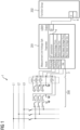
- the Figure 1 shows a known embodiment of an assignment of measuring transformers A, B, C of an electrical power network with the three phases L1, L2, L3 to functional groups 202 of a protective device.
- Primary measuring transformers A, B, C are each connected to a phase L1, L2, L3 of the power network. They provide a measuring voltage for each phase L1, L2, L3 to a protective device (dashed box around the internal secondary measuring transformers for the voltages V1, V2, V3, V4).
- Primary measuring transformers A, B, C and the protective device together form a protective arrangement 200.
- the protective device has processor and data storage means so that measuring point routing can be carried out for the analog input signals.
- the voltages V1...V4 are provided by software as a three-phase measured value module 201 and assigned to the inputs PhsA/AB, PhsB/BC, PhsC/CA, VN (neutral).
- the type of measurement is set to "VT connection" 4 ("VT" for "voltage transformer”).
- the local network station to which the protective device is assigned is designated "UD01" 5.
- the three-phase measured value module provides the voltages as input variables to various protective functions via software (indicated by the reference number 6).
- the configuration of the measured value module and the protective functions is typically carried out by a technician using a so-called "engineering tool".
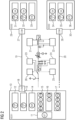
- FIG. 2 shows an example of a protective arrangement connected via a process bus.
- an example electrical network is shown in which measuring transformers are provided as measuring devices at several measuring points. These measuring devices are connected via analog cable connection to data collection devices 21, 22, 23, 24, which are also referred to as so-called “merging units”.
- I_O_modules 25, 26 are provided for a circuit breaker and an earthing switch, each of which records the switch position (open/closed) in binary form.
- the data collection devices 21, 22, 23, 24 and the I_O modules 25, 26 are redundantly connected to two process bus rings 19, 20 via digital data communication.
- the process bus rings are data cables that enable the sending of so-called GOOSE messages for power and reactive power values, control commands, regulation commands and protective functions, among other things.
- the data collection devices 21, 22, 23, 24 and the control devices 25, 26 each have communication devices for the process bus.
- IED01, IED02, IED03 Three "Intelligent Electronic Devices" (IED01, IED02, IED03) 10,29,30 are provided, each of which can provide protection functions, for example.
- the IEDs can be, for example, protection and control devices of the Siemens SIPROTEC 5 type mentioned above.
- the device 10 has several protection function groups 11-17 implemented in software, each of which is assigned the function identifiers typical in protection technology, the so-called "American National Standards Institute” (ANSI) numbers, such as 87T or 50BF (switch failure protection).
- the following are monitored, for example: circuit breaker 12,13, automatic voltage control 14, first transformer side 15, second transformer side 16, and access line (feeder) 17.
- the device 29 monitors: circuit breaker 31,32, "busbar differential" 33.
- the device 30 has the same monitoring functions, here marked with the reference numerals 34-36, like the device 29.
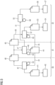
- the Figure 3 shows a familiar flow chart or workflow for configuring a protection arrangement, as used for an installation with a process bus according to the IEC61850-6 standard, for example for the well-known SIPROTEC protection device.
- the previous engineering of the digital current and voltage transformer channels from the merging units to the process bus client is linked to four different configuration tools.
- areas 60, 61, 62 represent different aspects of parameterizing a protection arrangement.
- Area 60 concerns the data collection device or merging unit 60, area 61 the system configuration and area 62 the process bus or the data communication connections.
- the first configuration tool 42 used is a so-called "Merging Unit Engineering Tool", which can be provided, for example, as a software component in the DIGSI software mentioned above.
- This tool provides a configuration file 41 for the data collection device 40 so that it can be parameterized and operated using the configuration file.
- the effective range of the first configuration tool is indicated by the reference number 63.
- a manufacturer-independent "System Configurator” is used as the second configuration tool 47.
- a configuration file 44 "Station SCD file” can be transmitted 46 from this tool, which brings together the merging unit and the client - i.e. the protective device.
- the configuration file 44 is transmitted 43 to the first configuration tool 42, which in turn provides a configuration file 48 "Merging Unit IID file” that is imported into the System Configurator 47.
- the effective range of the second configuration tool is indicated by the reference symbol 64.
- a configuration file 49 "Process bus client IID file” serves as a further input for the system configurator 47, which is also transmitted 50 to a third configuration tool 52 "Process bus Client Engineering Tool", which can also be provided using DIGSI.
- the configuration file 44 which is transmitted 45, also serves as input for the third configuration tool 52.
- the third configuration device 52 is used to create a further configuration file 53 (e.g. a "SIPROTEC 5 CFG file”), which is used to configure the "Process bus client device” 54, e.g. a protection device.
- the effective range of the third configuration tool is indicated by the reference number 65.
- the fourth configuration tool 55 "Process Bus Client Configuration Tool” receives input 51 from the system configurator 46, namely so-called "SCD import connected channels”. This enables the creation of a configuration file 56 "Process Bus Configuration file”, which is made available to a "Process Bus Client Board”.
- the effective range of the fourth configuration tool is indicated by the reference number 66.
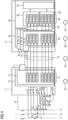
- Figure 4 shows an embodiment of a known assignment of measuring transformer channels to a data collection device and a protection device, ie a previous configuration assignment of the digital current and voltage transformer channels from the merging unit to the process bus client.
- a three-phase electrical power network with phases L1, L2, L3 has measuring transformers 70 as measuring devices, which are connected in an analog manner to a data collection device 71 or a merging unit.
- This has a first software component 72, which in turn is equipped with a measurement data acquisition 73.
- the measurement data acquisition 73 assigns a "logical node" LN (identified with reference number 75) to each analog input channel, i.e., for example, a current value I1 is assigned a representation LN TCTR1 ("logical node transformer current transformer 1") or a voltage value V2 is assigned a representation LN TVTR2 ("logical node transformer voltage transformer 1").
- the current and voltage transformers are shown as single-phase elements TCTR and TVTR respectively.
- the current and voltage transformer connections or the assignment to the physical measuring points are not taken into account.
- the complex configuration steps or multiple manual assignments, such as the device-internal assignment, allow errors.
- a flexible division of the input channels of the process bus client into only required currents and voltages is not possible.
- the lack of flexibility is particularly disadvantageous when the number of channels is increased.
- the configuration of the merging unit falls within the effective range 63 of the first configuration tool according to Figure 3 .
- the representations 75 are transmitted via a communication device for Ethernet 74.
- the assignment 76 is made via process bus to the correct receiver device 77 according to a configuration in the effective range 64 of the second configuration tool according to Figure 3 .
- the receiver device 77 is a protective device that can monitor several objects simultaneously or process input signals from several merging units in parallel. For this purpose, several copies or instances 78,79,80 of an input device for Ethernet and a process bus configuration PB_1A, PB_2A, PB_3A are operated in software.
- the process bus configuration PB_3A is shown as an example, which provides the representation 85 from the merging unit for further processing.
- the configuration of the process bus in the protective device falls within the effective range 66 of the fourth configuration tool according to Figure 3 .
- An assignment 84 of the measured values or representations 85 to the main application protection functions 83 takes place, in particular to instantiated measured value modules 88,89 for current and voltage.
- This configuration in the protection device falls within the effective range 65 of the third configuration tool according to Figure 3 If protective functions are triggered, the corresponding trigger signals are transmitted to a device 87 for Preparation of control commands for a line feeder. In this way, the protective device can be used to act on circuit breakers in the electrical power network.
- the transmitter side is therefore configured in relation to the data-receiving protection device.
- the implicit routing ensures flexible and simplified assignment.
- the name of the source of the SV stream of the merging unit is displayed in the properties window of the measuring point after connection in the system configuration tool.
- FIG. 6 A particularly simple way to parameterize the protective arrangement is provided according to Figure 6 This is provided by the fact that the physical current and voltage transformers can be interconnected in the engineering tool's single line editor. In addition to the interconnection to the merging units, a communication interconnection directly to the process bus client is required. This communication interconnection can be displayed in a different color in real software, for example.
- the Figure 6 shows a schematic graphical configuration using a "Single Line Diagram" representation in the engineering tool for a transformer and line protection according to the example network 101 from Figure 2
- the single line diagram describes the primary system and can be created automatically, for example, using information from a so-called SSD file of the local network station.
- the primary system can be drawn by a user using predefined components (e.g. transformer, measuring transducer).
- the user has already graphically created the connections shown, which were then automatically converted into configuration files according to the configuration tools described in the previous figures.
- the data communication connections 102 are current measurement values transmitted via process bus.
- the data communication connections 103 are voltage measurement values transmitted via process bus.
- Data communication connections 106,107 describe transformer switching positions that are transmitted to the merging units 104,105.
- the connections 109,120 transmit voltage measurement values from the transformers and the connections 108,121 transmit current measurement values from the transformers to the merging units 104,105.
- An import from the system configuration tool into the DIGSI tool to set up the process bus client is carried out by automatically transferring the parameters of the current transformers and voltage transformers of the merging units to the process bus client when importing the SCD file into DIGSI. This ensures the consistency of all settings, for example the parameters for the primary transformer (primary nominal current, transformation ratios).
- an instantiable measurement value module in the sense of the invention is a bundle - depending on the connection type - of three or four current or voltage channels to be transmitted.
Landscapes
- Emergency Protection Circuit Devices (AREA)
- Remote Monitoring And Control Of Power-Distribution Networks (AREA)
Description
- Die Erfindung betrifft ein Verfahren gemäß dem Oberbegriff des Anspruchs 1, eine Schutzanordnung gemäß Anspruch 7 sowie ein Computerprogrammprodukt gemäß Anspruch 13.
- In Energienetzen der Hoch- und Mittelspannungsebene werden elektrische Anlagen, wie z.B. Transformatoren oder Schaltanlagen, mittels Messeinrichtungen überwacht, die beispielsweise Spannungswerte und Stromwerte dreiphasig messen und bereitstellen. Eine gängige Bauform ist es, primäre Messwandler an der elektrischen Anlage einzusetzen, die analoge elektrische Größen wie Spannung und Stromstärke an Anschlussklemmen eines Schutzgeräts bereitstellen. Im Schutzgerät werden häufig sekundäre Messwandler für eine galvanische Trennung der Elektronik des Schutzgeräts eingesetzt.
- Bei der Überwachung, der Steuerung und dem Schutz von elektrischen Energienetzen sind eine Vielzahl von verschiedenen Strömen und Spannungen in unterschiedlichen Anlagentopologien zu erfassen. In multifunktionalen Schutzgeräten werden unterschiedlichste Schutz-, Steuerungs- und Messaufgaben in einem Gerät realisiert. Weiterhin können von einem multifunktionalen Gerät mehrere Schutzobjekte geschützt werden.
- Aus der Druckschrift
WO 2008/104140 A1 ist es bekannt, eingehende analoge elektrische Signale an einer Mehrzahl von Messeingängen eines Schutzgeräts zu erfassen und zur Auswertung für softwarebasierte Schutzfunktionen sowie Schalterfunktionen auf einem Prozessor bereit zu stellen, wobei Vorverarbeitungseinrichtungen zur Übersetzung der analogen Eingangssignale in digitale Messwerte dienen. - Aus der Druckschrift
WO 2009/030258 A1 ist es bekannt, eine Anschaltung bzw. Konfiguration konventioneller Strom- und Spannungswandler als sogenannte "instanziierbare Messwertmodule" an einem multifunktionalem Schutzgerät vorzunehmen. Bei den instanziierbaren Messwertmodulen handelt es sich um Softwarekomponenten, die bei der Projektierung bzw. Parametrierung eines Schutzgeräts eingestellt werden, um die analogen Eingangssignale der Anschlussklemmen des Schutzgeräts zu digitalisieren und den passenden Auswertungs- und Steuerungsfunktionen zuzuführen. Der Begriff instanziierbar stellt dabei darauf ab, dass die Messwertmodule als ein Grundtyp eines Messwertmoduls vordefiniert werden können, welcher danach mehrfach zur Parametrierung von z.B. mehreren zu überwachenden Objekten wiederverwendet werden kann (in Form von softwaremäßigen "Instanzen" des Grundtyps). Insbesondere werden instanziierbare Messmodule für Strom- und Spannungswandlereinheiten beschrieben, wobei die vier Grundtypen Strom 3-phasig, Strom 1-phasig, Spannung 3-phasig und Spannung 1-phasig zugrunde gelegt wurden. - Aus der Druckschrift
WO 2012/022374 A2 ist ein Verfahren zum Parametrieren einer Schutzanordnung bekannt. - Ferner ist aus der Produktbroschüre "SIPROTEC 5 - V7.9 und V8.0 Schutz, Automatisierung und Überwachung von digitalen Schaltanlagen", Siemens AG 2019, von den Seiten 22 bis 32 bekannt, ein Schutzgerät per Prozessbus über Glasfaserkabel mit sogenannten "Merging Units", d.h. Datensammelungseinrichtungen, zu verbinden. Die Merging Units sind dabei analog per Kupferkabel an Messstellen einer elektrischen Anlage, z.B. einer gasisolierten Schaltanlage für Hochspannung über 1 kV, angeschlossen. Aus der Broschüre "SIPROTEC goes Process Bus - Volldigitale Schaltanlagen mit SIPROTEC" ist es bekannt, konventionelle bisherige Schaltanlagen mit einer Merging Unit zu verbinden, um analoge Messwerte wie Strom- und Spannungswerte (sog. "samples measured values" (SMV)) zu erfassen und diese als digitale Datentelegramme per Prozessbus zum Schutzgerät zu übermitteln. Der Prozessbus wird dabei entsprechend der Norm IEC 61850-9-2 betrieben.
- Weiterhin ist aus der Ferner Produktbroschüre "SIPROTEC 5 Engineering Guide DIGSI 5 ab V6.0 Handbuch", Siemens AG 2015, Kennnummer C53000-G5000-C004-2, sowie aus "DIGSI 5 Software-Beschreibung V8.00 Hilfe", Siemens AG 2019, Kennnummer C53000-D5000-C001-G, eine Software zum Parametrieren von Schutzanordnungen bekannt.
- Die Anschaltung der Strom- und Spannungswandler an das multifunktionale Schutzgerät erfolgt in der Prozessbusanbindung nicht mehr über die Geräteeingangsklemmen und Wandlung der analogen Signale in dem multifunktionalen Schutzgerät, sondern über o.g. Merging Units als digitale Messwandler.
- Die digitalisierten Abtastwerte werden von den Merging Units zu dem Schutzgerät nach der Norm IEC 61850 9-2 übertragen und eine Auslösung von z.B. Leistungsschalters infolge einer Aktivierung einer Schutzfunktion im Schutzgerät erfolgt im Rahmen der Norm IEC 61850 GOOSE 8-1.
- Das Verfahren der Übertragung der Abtastwerte über den Prozessbus ist standardisiert und in der Norm IEC 61850-9-2 Ed.2 Part 9-2 "Specific communication service mapping (SCSM) - Sampled Values over ISO/IEC 8802-3" beschrieben. Das Engineering, die Sprache, die Dateien und die verwendeten Tools z.B. das herstellerübergreifende Systemkonfigurationswerkzeug (im Folgenden auch als "System Configurator" bezeichnet) sind im Standard IEC 61850-6 beschrieben.
- Ausgehend von bekannten Verfahren zum Parametrieren einer Schutzanordnung stellt sich an die Erfindung die Aufgabe, ein Verfahren anzugeben, mit dem eine Schutzanordnung vergleichsweise einfach, schnell und sicher in Betrieb zu nehmen ist.
- Die Erfindung löst diese Aufgabe durch ein Verfahren gemäß Anspruch 1.
- Ein elektrisches Energienetz ist beispielsweise ein Hochspannungsnetz mit über 52 kV Nennspannung, oder ein Mittelspannungsnetz mit 1 kV bis 52 kV Nennspannung. Solche Energienetze weisen Transformatoren an Leitungsabgängen auf, die z.B. im Hinblick auf Kurzschlüsse usw. überwacht werden müssen. Wird ein Fehler durch entsprechende Messungen entdeckt, so kann eine Schutzeinrichtung einen Schaltbefehl über eine Kommunikationsverbindung an einen Leistungsschalter übermitteln, der dann den Transformator und/oder die Leitung abschaltet.
- Parametrieren im Sinne der Erfindung ist eine Vorgehensweise, bei der die Software eines oder mehrere Geräte für den Betrieb eingestellt wird.
- Messeinrichtungen sind z.B. Spannungswandler und/oder Stromwandler, die entsprechend ihres Übersetzungsverhältnisses eine vergleichsweise kleine Ausgabespannung als analoges Ausgabesignal auf ihren Ausgabekanälen bzw. an ihren Ausgabeanschlüssen bereitstellen.
- In modernen Anlagen werden diese analogen Signale nicht direkt an ein Schutzgerät übergeben, sondern in sog. "Merging Units" als Datensammelungseinrichtungen digitalisiert und zusammengefasst. Hierdurch wird eine Anbindung an eine digitale Datenkommunikationsinfrastruktur wie z.B. einen Prozessbus möglich.
- Als erste Konfigurationseinrichtung kann beispielsweise die Software DIGSI der Siemens AG, die auf einem Rechner installiert ist, eingesetzt werden. Insbesondere kann ein sog. "Merging Unit Routing" im sog. "Merging Unit Engineering Tool" durchgeführt werden.
- Als zweite Konfigurationseinrichtung für die Datenkommunikation kann ebenfalls DIGSI eingesetzt werden.
- Auch als dritte Konfigurationseinrichtung kann DIGSI eingesetzt werden, um anhand eines Single-line Diagramms z.B. Strom- und Spannungswandler über einen Prozessbus-Client zu verschalten.
- Damit kann die Funktionalität der drei Konfigurationseinrichtungen z.B. im Wesentlichen durch Software z.B. auf einem Rechner eines Technikers bereitgestellt werden. Lediglich der durch die Norm geforderte herstellerunabhängige System Configurator muss als separate Software vorgesehen werden.
- Die Konfigurationseinrichtungen können lokal als Rechner mit Prozessor- und Datenspeichermitteln ausgebildet sein. Alternativ kann auch eine cloud-basierte Lösung vorsehen werden (sog. "Protection in the cloud"), bei der alle Schutzfunktionen als Softwareapplikationen bereitgestellt werden. Eine Cloud im Sinne der Erfindung ist ein Netzwerk aus Datenspeicher- und Prozessormitteln, die mittels eines Datenkommunikationsnetzwerks, wie z.B. des Internets, dezentral bereitgestellt werden.
- In einer bevorzugten Ausführungsform des erfindungsgemäßen Verfahrens wird die parametrierte Schutzanordnung für den Betrieb des elektrischen Energienetzes eingesetzt, um mindestens einen Transformator und mindestens einen Leitungseingang zu überwachen und zu schützen.
- Es wird für die Kommunikationsverbindungen Prozessbus verwendet. Dies ist ein Vorteil, weil Prozessbus weit verbreitet und erprobt ist sowie eine sichere digitale Datenübertragung ermöglicht.
- In einer weiteren bevorzugten Ausführungsform des erfindungsgemäßen Verfahrens weisen die Kommunikationsverbindungen zwei redundante Prozessbusringe auf. Dies ist ein Vorteil, weil auch bei einem Ausfall eines Prozessbusringes durch den anderen Prozessbusring eine Überwachung und ein Schutz sichergestellt werden kann.
- In einer weiteren bevorzugten Ausführungsform des erfindungsgemäßen Verfahrens erfolgt das Zuordnen der Ausgabekanäle von Messeinrichtungen zu Eingabekanälen der Datensammelungseinrichtung jeweils mittels Messwertmodulen, die Messwerte von dreiphasiger Spannung und/oder dreiphasigen Strom jeweils bündeln. Dies ist ein Vorteil, weil sich durch die Bündelung der Kanäle eine vereinfachte Parametrierung der Schutzanordnung ergibt. Beispielsweise muss nur ein Messwertmodul durchgehend durch die verschiedenen Konfigurationseinrichtungen behandelt werden anstatt 3 einzelne Messwertkanäle.
- In einer weiteren bevorzugten Ausführungsform des erfindungsgemäßen Verfahrens werden die Messwertmodule in der Schutzeinrichtung für Schutzfunktionen verwendet. Dies ist ein Vorteil, weil sich durch die Bündelung der Kanäle zu Messwertmodulen auch bei der Konfiguration der Schutzfunktionen im Schutzgerät eine vereinfachte und schnellere Vorgehensweise ergibt.
- In einer weiteren bevorzugten Ausführungsform des erfindungsgemäßen Verfahrens sind die Messwertmodule derart instanziierbar, dass mehrere elektrische Betriebsmittel über dieselbe Datensammelungseinrichtung und eine einziges Schutzeinrichtung überwacht und geschützt werden. Bei den instanziierbaren Messwertmodulen handelt es sich um Softwarekomponenten, die bei der Projektierung bzw. Parametrierung eines Schutzgeräts eingestellt werden, um die analogen Eingangssignale der Anschlussklemmen des Schutzgeräts zu digitalisieren und den passenden Auswertungs- und Steuerungsfunktionen zuzuführen. Der Begriff instanziierbar stellt dabei darauf ab, dass die Messwertmodule als ein Grundtyp eines Messwertmoduls vordefiniert werden können, welcher danach mehrfach zur Parametrierung von z.B. mehreren zu überwachenden Objekten wiederverwendet werden kann (in Form von softwaremäßigen "Instanzen" des Grundtyps). Insbesondere werden instanziierbare Messmodule für Strom- und Spannungswandlereinheiten beschrieben, wobei die vier Grundtypen Strom 3-phasig, Strom 1-phasig, Spannung 3-phasig und Spannung 1-phasig zugrunde gelegt wurden. Dies hat den Vorteil, dass eine durchgehende Behandlung der Messdaten von einer Merging Unit bis zu den Schutzfunktionen im Schutzgerät hin möglich wird, was die Parametrierung der Messstellenrangierung und der Schutzfunktionen wesentlich vereinfacht.
- Ferner stellt sich, ausgehend von bekannten Schutzanordnungen, an die Erfindung die Aufgabe, eine Schutzanordnung anzugeben, die vergleichsweise einfach, schnell und sicher in Betrieb zu nehmen ist.
- Die Erfindung löst diese Aufgabe durch ein Verfahren gemäß Anspruch 7. Bevorzugte Ausführungsformen ergeben sich aus den abhängigen Ansprüchen 8 bis 12. Dabei ergeben sich sinngemäß die gleichen Vorteile wie eingangs für das erfindungsgemäße Verfahren erläutert.
- Ferner stellt sich an die Erfindung die Aufgabe, ein Computerprogrammprodukt anzugeben, mit dem eine Schutzanordnung vergleichsweise einfach, schnell und sicher in Betrieb zu nehmen ist.
- Die Erfindung löst diese Aufgabe durch ein Computerprogrammprodukt gemäß Anspruch 13. Es ergeben sich sinngemäß die gleichen Vorteile wie eingangs für das erfindungsgemäße Verfahren erläutert.
- Zur besseren Erläuterung der Erfindung zeigen in schematischer Darstellung die
- Figur 1
- ein bekanntes Ausführungsbeispiel einer Zuordnung von Messwandlern eines elektrischen Energienetzes zu Funktionsgruppen eines Schutzgeräts, und
- Figur 2
- ein Ausführungsbeispiel für eine per Prozessbus verschaltete Schutzanordnung, und
- Figur 3
- einen bekannten Ablaufplan für eine Konfiguration einer Schutzanordnung, und
- Figur 4
- eine Ausführungsbeispiel einer bekannten Zuordnung von Messwandlerkanälen zu einer Datensammelungseinrichtung und einer Schutzeinrichtung, und
- Figur 5
- ein Ausführungsbeispiel einer erfindungsgemäßen Messstellenrangierung mit Prozessbus, und
- Figur 6
- ein Ausführungsbeispiel für eine erfindungsgemäße graphische Zuordnung von Messeinrichtungen und eine Parametrierung der Kommunikationsverbindungen anhand eines Single-line Diagramms.
- Die
Figur 1 zeigt ein bekanntes Ausführungsbeispiel einer Zuordnung von Messwandlern A,B,C eines elektrischen Energienetzes mit den drei Phasen L1,L2,L3 zu Funktionsgruppen 202 eines Schutzgeräts. Primäre Messwandler A,B,C sind mit jeweils einer Phase L1,L2,L3 des Energienetzes verbunden. Sie stellen eine Messspannung für jede Phase L1,L2,L3 an ein Schutzgerät (gestrichelter Kasten um die internen sekundären Messwandler für die Spannungen V1,V2,V3,V4) bereit. Primäre Messwandler A,B,C und das Schutzgerät bilden zusammen eine Schutzanordnung 200. - Das Schutzgerät weist Prozessor- und Datenspeichermittel auf, so dass eine Messstellenrangierung für die analogen Eingangssignale vorgenommen werden kann. Die Spannungen V1...V4 werden softwareseitig als dreiphasiges Messwertmodul 201 bereitgestellt und den Eingängen PhsA/AB, PhsB/BC, PhsC/CA, VN (Neutral) zugeordnet. Im Messwertmodul 201 wird als Art der Messung "VT connection" 4 festgelegt ("VT" für "voltage transformer"). Die Ortsnetzstation, der das Schutzgerät zugeordnet ist, wird mit "UD01" 5 bezeichnet. Das dreiphasige Messwertmodul stellt die Spannungen softwaremäßig verschiedenen Schutzfunktionen als Eingangsgrößen bereit (angedeutet durch das Bezugszeichen 6). Die Konfiguration des Messwertmoduls und der Schutzfunktionen erfolgt typischerweise durch einen Techniker mittels eines sog. "Engineering Tools".
-
Figur 2 zeigt ein Ausführungsbeispiel für eine per Prozessbus verschaltete Schutzanordnung. Mittig in der Abbildung ist ein elektrisches Beispielnetz gezeigt, bei dem an mehreren Messtellen Messwandler als Messeinrichtungen vorgesehen sind. Diese Messeinrichtungen sind per analoge Kabelverbindung mit Datensammelungseinrichtungen 21,22,23,24 verbunden, die auch als sog. "Merging Units" bezeichnet werden. Ferner sind sog. I_O_Module 25,26 für einen Leistungsschalter und einen Erdungsschalter vorgesehen, die jeweils binär die Schalterstellung (offen/geschlossen) erfassen. - Die Datensammelungseinrichtungen 21,22,23,24 sowie die I_O_Module 25,26 sind redundant, per digitaler Datenkommunikation, an zwei Prozessbusringe 19,20 angeschlossen. Beispielsweise handelt es sich bei den Prozessbusringen um Datenkabel, die ein Versenden von sog. GOOSE-Nachrichten für u.a. Leistungs- und Blindleistungswerte, Steuerbefehle, Regelungsbefehle und Schutzfunktionen ermöglichen. Hierfür weisen die Datensammelungseinrichtungen 21,22,23,24 sowie die Steuergeräte 25,26 jeweils Kommunikationseinrichtungen für Prozessbus auf.
- Es sind drei "Intelligent Electronic Devices " (IED01, IED02, IED03) 10,29,30 vorgesehen, die jeweils z.B. Schutzfunktionen bereitstellen können. Bei den IEDs kann es sich z.B. um Schutz- und Steuergeräte des eingangs erwähnten Typs Siemens SIPROTEC 5 handeln.
- Beispielsweise weist das Gerät 10 mehrere in Software ausgebildete Schutzfunktionsgruppen 11-17 auf, zu denen jeweils die in der Schutztechnik typischen Funktionsbezeichner, die sog. "American National Standards Institute" (ANSI) - Nummern, wie z.B. 87T oder 50BF (Schaltversagerschutz) angegeben sind. Es werden z.B. überwacht: Leistungsschalter 12,13, Automatische Spannungskontrolle 14, Erste Transformatorseite 15, Zweite Transformatorseite 16, und Zugangsleitung (Feeder) 17. Das Gerät 29 überwacht: Leistungsschalter 31,32, "Busbar Differential" 33. Das Gerät 30 weist die gleichen Überwachungsfunktionen, hier mit den Bezugszeichen 34-36 gekennzeichnet, wie das Gerät 29 auf.
- Die
Figur 3 zeigt einen bekannten Ablaufplan bzw. Workflow für eine Konfiguration einer Schutzanordnung, wie er für eine Installation mit Prozessbus nach dem Standard IEC61850-6 beispielsweise für das bekannte SIPROTEC Schutzgerät verwendet wird. Das bisherige Engineering der digitalen Strom- und Spannungswandlerkanäle von den Merging Units bis zum Prozessbus-Client ist mit vier verschiedenen Konfigurationstools verknüpft. In der schematischen Darstellung stehen die Bereiche 60,61,62 für unterschiedliche Aspekte der Parametrierung einer Schutzanordnung. Bereich 60 betrifft die Datensammelungseinrichtung bzw. Merging Unit 60, Bereich 61 die Systemkonfiguration und Bereich 62 den Prozessbus bzw. die Datenkommunikationsverbindungen. - Als erstes Konfigurationstool 42 kommt ein sog. "Merging Unit Engineering Tool" zum Einsatz, das z.B. als Softwarekomponente in der eingangs genannten Software DIGSI bereitgestellt werden kann. Dieses Tool stellt eine Konfigurationsdatei 41 für die Datensammelungseinrichtung 40 bereit, so dass diese mittels der Konfigurationsdatei parametriert und betrieben werden kann. Der Wirkbereich des ersten Konfigurationstools ist mit dem Bezugszeichen 63 angedeutet.
- Als zweites Konfigurationstool 47 kommt ein herstellerunabhängiger "System Configurator" zum Einsatz. Aus diesem Tool kann eine Konfigurationsdatei 44 "Station SCD file" übermittelt 46 werden, die die Merging Unit und den Client - also das Schutzgerät - zusammenführt. Die Konfigurationsdatei 44 wird an das erste Konfigurationstool 42 übermittelt 43, welches wiederum eine Konfigurationsdatei 48 "Merging Unit IID file" bereitstellt, die in den System Configurator 47 importiert wird. Der Wirkbereich des zweiten Konfigurationstools ist mit dem Bezugszeichen 64 angedeutet.
- Als weiterer Input für den System Configurator 47 dient eine Konfigurationsdatei 49 "Prozessbus client IID file", die ferner auch an ein drittes Konfigurationstool 52 "Prozessbus Client Engineering Tool" übermittelt wird 50, das ebenfalls mittels DIGSI bereitgestellt werden kann. Für das dritte Konfigurationstool 52 dient ebenfalls die Konfigurationsdatei 44 als Input, die übermittelt wird 45. Mittels der dritten Konfigurationseinrichtung 52 wird eine weitere Konfigurationsdatei 53 (z.B. ein "SIPROTEC 5 CFG file") erstellt, die zur Konfiguration des "Prozessbus Client Device" 54, z.B. eines Schutzgeräts, verwendet wird. Der Wirkbereich des dritten Konfigurationstools ist mit dem Bezugszeichen 65 angedeutet.
- Das vierte Konfigurationstool 55 "Prozessbus Client Configuration Tool" erhält Input 51 vom System Configurator 46, nämlich sog. "SCD import connected channels". Dies ermöglicht die Erstellung einer Konfigurationsdatei 56 "Prozessbus Configuration file", welche einem "Prozessbus Client Board" zur Verfügung gestellt wird. Der Wirkbereich des vierten Konfigurationstools ist mit dem Bezugszeichen 66 angedeutet.
-
Figur 4 zeigt ein Ausführungsbeispiel einer bekannten Zuordnung von Messwandlerkanälen zu einer Datensammelungseinrichtung und einer Schutzeinrichtung, d.h. eine bisherige Konfigurationszuordnung der digitalen Strom- und Spannungswandlerkanäle von der Merging Unit bis zum Prozessbus-Client. - Ein dreiphasiges elektrisches Energienetz mit den Phasen L1,L2,L3 weist Messwandler 70 als Messeinrichtungen auf, die analog an eine Datensammelungseinrichtung 71 bzw. eine Merging Unit angeschlossen sind. Diese weist eine erste Softwarekomponente 72 auf, die wiederum mit einer Messdatenerfassung 73 ausgestattet ist. Die Messdatenerfassung 73 ordnet jedem analogen Eingangskanal einen "logical node" LN zu (mit Bezugszeichen 75 gekennzeichnet), also z.B. einem Stromwert I1 eine Repräsentation LN TCTR1 ("logical node transformer current transformer 1") oder einem Spannungswert V2 eine Repräsentation LN TVTR2 ("logical node transformer voltage transformer 1"). Die Strom- und Spannungswandler sind als einphasige Elemente TCTR bzw. TVTR abgebildet. Die Strom- und Spannungswandleranschlüsse bzw. die Zuordnung zu den physikalischen Messstellen werden nicht berücksichtigt. Durch die komplexen Projektierungsschritte bzw. vielfachen manuellen Zuordnungen, wie z.B. der geräteinternen Zuordnung werden Fehler ermöglicht. Eine flexible Aufteilung der Eingangskanäle des Prozessbus-Clients in nur benötigte Ströme und Spannungen ist nicht möglich. Die fehlende Flexibilität ist insbesondere bei erhöhter Kanalanzahl nachteilig. Die Konfiguration der Merging Unit fällt in den Wirkbereich 63 des ersten Konfigurationstools gemäß
Figur 3 . - Die Repräsentationen 75 werden über eine Kommunikationseinrichtung für Ethernet 74 übermittelt. Dabei erfolgt die Zuordnung 76 über Prozessbus zum korrekten Empfängergerät 77 entsprechend einer Konfiguration im Wirkbereich 64 des zweiten Konfigurationstools gemäß
Figur 3 . - Das Empfängergerät 77 ist ein Schutzgerät, das mehrere Objekte gleichzeitig überwachen bzw. Eingangssignale mehrerer Merging Units parallel verarbeiten kann. Hierfür werden softwaremäßig mehrere Kopien bzw. Instanzen 78,79,80 einer Eingangseinrichtung für Ethernet und einer Prozessbuskonfiguration PB_1A, PB_2A, PB_3A betrieben. Beispielhaft ist die Prozessbuskonfiguration PB_3A dargestellt, die die Repräsentation 85 aus der Merging Unit zur weiteren Verarbeitung bereitstellt. Die Konfiguration des Prozessbusses im Schutzgerät fällt in den Wirkbereich 66 des vierten Konfigurationstools gemäß
Figur 3 . - Es findet eine Zuordnung 84 der Messwerte bzw. Repräsentationen 85 zur Hauptanwendung Schutzfunktionen 83 statt, insbesondere zu instanziierten Messwertmodulen 88,89 für Strom und Spannung. Diese Konfiguration im Schutzgerät fällt in den Wirkbereich 65 des dritten Konfigurationstools gemäß
Figur 3 . Werden Schutzfunktionen ausgelöst, so erfolgt eine Übergabe von entsprechenden Auslösesignalen an eine Einrichtung 87 zur Vorbereitung von Steuerbefehlen für einen Leitungsabgang (Feeder). Auf diese Weise kann mittels des Schutzgeräts auf Leistungsschalter im elektrischen Energienetz rückgewirkt werden. - Im Einzelnen umfassen die Konfigurationsschritte für das erste Konfigurationstool 42 (Merging Unit Engineering Tool) mit Wirkbereich 63:
- Vorbereiten der zu übertragenden Strom- und Spannungswandlerkanäle der Merging Unit in Übereinstimmung mit dem IEC61850 Objektmodell
- Parametrieren eines fest vordefinierten Übertragungsumfangs von 4 Strömen und 4 Spannungen gemäß IEC61850-9-2 LE (Lite Edition) TCTR1..4, TVTR1..4 .
- Die Konfigurationsschritte für das dritte Konfigurationstool 52 (Prozessbus-Client Engineering Tool) mit Wirkbereich 65 umfassen:
- Instanziierung des Prozessbus-Client Moduls
- zwei feste vordefinierte Konfigurationen von 12 Strömen und 12 Spannungen oder 24 Strömen sind im Prozessbus-Client Modul verfügbar
- Instanziierung der Messstellen im Prozessbus Client analog direkt angeschalteter Kanäle
- Die einzelnen Phasen eines dreiphasigen Messwertmodules werden separat auf die Kanäle des Prozessbus-Client Moduls verschaltet.
- Die Konfigurationsschritte für das zweite Konfigurationstool 47 (System Configurator) mit Wirkbereich 64 umfassen:
- Verknüpfung von IID Dateien der Merging Units und der Prozessbus-Clients in einer Stationskonfigurationsdatei (SCD)
- Verbinden der einzelnen einphasigen Stromwandlerinstanzen TCTR bzw. Spannungswandlerinstanzen TVTR der Merging Unit (Source) mit denen des Prozessbus Client (Destination) in der Ansicht "Sampled Measured Values (SMV)".
- Die "Sampled Measured Values (SMV)" stellen z.B. Ströme, Spannungen und Abtastraten der Merging Unit bereit.
- Der Empfänger LN ist der IEC61850 Name aus IED und LN Name des TCTR bzw. TVTR.
- Die Konfigurationsschritte für das vierte Konfigurationstool 55 (Prozessbus Client Configuration Tool) mit Wirkbereich 66 umfassen:
- Die Prozessbus Client Konfiguration erfolgt mit einem separaten Prozessbuskonfigurationstool.
- Um ein Signal einer Merging Unit einem Kanal der Prozessbusbaugruppe zuzuordnen gibt es in dem Tool
- Im Folgenden soll nun auf die erfindungsgemäßen Verbesserungen des bisherigen Verfahrens eingegangen werden.
- Es wird vorgeschlagen, im Merging Unit Engineering Tool eine neue separate Ansicht "Merging Unit Routing" bereitzustellen. Diese ermöglicht zwei Vereinfachungen:
- a. Eine Instanziierung eines Messmoduls Strom/Spannung 3-phasig/ 1-phasig aus der Funktionsbibliothek sowie Festlegen der Anschlussartart und Zuordnung zu den Geräteeingangskanälen in der Ansicht Messtellenrangierung.
- b. In der neuen Ansicht "Merging Unit Routing" werden die Strom- und Spannungsmessmodule als Einheit den zu versendenden Sampled Values (SV) Streams zugeordnet. Über die Anschlussart wird fest die Anzahl der zu versendenden Kanäle vorgegeben. Ferner ist ein Stream Typ, zum Beispiel IEC61850 9-2 LE, auswählbar.
- Dieser Ansatz erlaubt eine vereinfachte Parametrierung der anlogen Eingänge der Merging Units. Es wird folglich die Senderseite in Bezug auf das datenempfangende Schutzgerät konfiguriert.
- Alternativ ist die Konfiguration der Zuordnung von instanziierbaren Messstellen im Single Line Diagramm auf die IEC 61850 9-2 SV Streams möglich (siehe dazu weiter unten
Figur 6 sowie die Ausführungen zur Konfiguration des Prozessbus-Client). - Ferner wird gemäß
Figur 5 vorgeschlagen, im Prozessbus-Client Engineering Tool 92 Veränderungen vorzunehmen. Die Funktionalität wird gekennzeichnet durch vereinfachte Konfigurierbarkeit im Engineering Tool durch den Anwender: - Instanziierung eines Messmoduls Strom/Spannung 3-phasig/ 1-phasig aus der Funktionsbibliothek
- Festlegen der Anschlussartart und Zuordnung zu den Geräteeingangskanälen in der Ansicht Messtellenrangierung 90
- In der Ansicht "Messstellenrangierung" ist eine neue Spalte 91 "Prozessbus" verfügbar. Hier können die Strom- und Spannungsmessmodule als Einheit bzw. Bündel dem Prozessbus zugeordnet werden. Über die Anschlussart wird implizit die Anzahl der zu empfangenen Kanäle vorgegeben. Dieser Ansatz erlaubt eine vereinfachte Parametrierung des Schutzgeräts. Es wird folglich die Empfängerseite in Bezug auf das datenempfangende Schutzgerät konfiguriert.
- Durch die implizite Rangierung wird eine flexible und vereinfachte Zuordnung gewährleistet. Im Eigenschaftsfenster der Messstelle wird der Name der Quelle des SV Streams der Merging Unit nach Verbindung im Systemkonfigurationstool angezeigt.
- Eine besonders einfache Möglichkeit zur Parametrierung der Schutzanordnung wird gemäß
Figur 6 dadurch bereitgestellt, dass die physikalischen Strom- und Spannungswandler im Single Line Editor des Engineering Tools verschaltbar sind. Dazu ist zusätzlich zu der Verschaltung zu den Merging Units eine Kommunikationsverschaltung direkt auf den Prozessbus-Client notwendig. Diese Kommunikationsverschaltung kann in einer realen Software zum Beispiel anders farblich dargestellt werden. - Die
Figur 6 zeigt dabei schematisch eine graphische Konfiguration anhand einer "Single Line Diagramm" - Darstellung im Engineering Tool für einen Transformator- und Leitungsschutz entsprechend dem Beispielnetz 101 ausFigur 2 . Das Single line diagramm beschreibt die Primäranlage und kann beispielsweise anhand von Informationen aus einem sog. SSD file der Ortsnetzstation automatisiert erstellt werden. Alternativ kann die Primäranlage durch einen Benutzer mittels vordefinierter Komponenten (z.B. Transformator, Messwandler) gezeichnet werden. - Es sind zwei Datensammelungseinrichtungen 104,105 bzw. Merging Units sowie das Schutz- und Steuergerät 110 (entspricht IED01 in
Figur 2 ) vereinfacht dargestellt. Die sieben Funktionsgruppen 11-17 gemäßFigur 2 sind als Kästen 111-117 angedeutet. Der Benutzer kann nun durch einfaches Anklicken von Messtellen und ziehen mit der Maus (oder einem anderen Manipulationsgerät) graphisch eine Verbindung zu einer Funktion im IED/ Schutzgerät oder in der Merging Unit parametrieren. Dies ist eine enorme Vereinfachung des bisher sehr komplexen Konfigurationsverfahrens. - Beispielshaft hat der Benutzer bereits die eingezeichneten Verbindungen graphisch hergestellt, die dann automatisiert in Konfigurationsdateien entsprechend der in den vorhergehenden Figuren beschriebenen Konfigurationstools umgewandelt wurden.
- Bei den Datenkommunikationsverbindungen 102 handelt es sich um per Prozessbus übertragene Strommesswerte. Bei den Datenkommunikationsverbindungen 103 handelt es sich um per Prozessbus übertragene Spannungsmesswerte. Datenkommunikationsverbindungen 106,107 beschreiben Transformatorschaltstellungen, die den Merging Units 104,105 übermittelt werden. Die Verbindungen 109,120 übermitteln Spannungsmesswerte von den Transformatoren und die Verbindungen 108,121 übermitteln Stromesswerte von den Transformatoren an die Merging Units 104,105.
- Die grafische Zuordnung der Verschaltung im Single Line Diagramm System wird nach Standard IEC61850 in einem "Specification Description file (.ssd)" gespeichert. Anhand dieser Information im SSD File und der Informationen im sog. "ICD File" werden nach einem Algorithmus bzw. einer Applikationsvorlage die Strom- und Spannungswandlerkanäle der Merging Units auf die Prozessbus-Client TCTR/ TVTR automatisiert verschaltet.
- Ein Import aus dem Systemkonfigurationstool in das Tool DIGSI zur Einrichtung des Prozessbus-Client erfolgt, indem beim Import der SCD Datei nach DIGSI die Parameter der Stromwandler und Spannungswandler der Merging Units automatisiert in den Prozessbus-Client übernommen werden. Damit wird die Konsistenz aller Einstellungen, zum Beispiel der Parameter für den Primärwandler (Primärnennstrom , Übersetzungsverhältnisse) gesichert.
- Zusammenfassend lässt sich feststellen, dass im Vergleich zu Verfahren des Standes der Technik beim erfindungsgemäßen Verfahren die Anwendung der instanziierbaren Messwertmodule Strom 3-phasig / Spannung 3-phasig auf die Konfiguration einer digitalen Prozessbusanwendung nach IEC61850 9-2 die Konfiguration einer Schutzanordnung vereinfacht. Bisher gab es in der Engineering Tool Kette vom Engineering Tool der Merging Unit, zum Systemkonfigurationstool bis zum Engineering Tool des Prozessbus Client keine durchgängige Behandlung der instanziierbaren Messwertmodule. Ein instanziierbares Messwertmodul ist im Sinne der Erfindung ein Bündel - entsprechend der Anschlussart - drei- oder vier zu übertragender Strom- oder Spannungskanäle.
- Die Verschaltung wird erfindungsgemäß insbesondere durch folgende neue Elemente bzw. Ansichten vereinfacht:
- 1.) Neue Ansicht "Merging Unit Routing" im Merging Unit Engineering Tool.
- 2.) Neue Spalte Prozessbus in der Messstellenrangierung des Prozessbus-Clients.
- 3.) Grafische Verschaltung von Strom- und Spannungswandler über Prozessbuskommunikation im Single Line Editor.
- 4.) Automatisiertes Verbinden der Sampled Values Sender und Empfänger im Systemkonfigurationstool anhand der Single Line Konfiguration
- 5.) Konsistente Datenübernahme der Einstellwerte von den Sender Datenobjekten TCTR/TVTR in die Empfänger Datenobjekte
- Hieraus ergeben sich eine Reihe von Vorteilen:
- 1.) Durch die Übernahme des Konzepts der Instanziierbarkeit der Messmodule und der Konfiguration der Anschaltung mit einem Parameter auf die Prozessbuskonfiguration entfällt die Komplexität der Einzelverschaltungen der Strom- und Spannungswandlerkanäle.
- 2. Die Instanziierbarkeit der Messmodule in der Merging Unit erlaubt eine hohe Flexibilität hinsichtlich der Übertragung von mehreren Strom- und Spannungsmessstellen oder in unterschiedlichen Prozessbusringen.
- 3. Durch eine Beschränkung auf die genutzte Kanalanzahl im Prozessbus-Client ergibt sich eine optimale Skalierung hinsichtlich der verwendeten internen Ressourcen (Bandbreite).
- 4. Die automatisierte Verschaltung im Systemkonfigurationstool und die Anwendung von Applikationsvorlagen spart Aufwand bei der Projektierung und reduziert mögliche Fehlverdrahtungen.
- 5. Die Usability der Projektierung wird durch die grafische Zuordnung und Visualisierung im Single Line Editor verbessert.
Zielspalte.
Claims (13)
- Verfahren zum Parametrieren einer Schutzanordnung (200,201,202) für ein elektrisches Energienetz (L1,L2,L3), mit den Schritten:Zuordnen von Ausgabekanälen (I1,I2,I3,I4,V1,V2,V3,V4) von Messeinrichtungen (70) zu Eingabekanälen (75) einer Datensammelungseinrichtung (71) mittels einer ersten Konfigurationseinrichtung, undParametrieren von Kommunikationsverbindungen (76) zwischen der Datensammelungseinrichtung (71) und einer Schutzeinrichtung (77) mittels einer zweiten Konfigurationseinrichtung,dadurch gekennzeichnet, dassdie Zuordnung der Messeinrichtungen (70) und die Parametrierung der Kommunikationsverbindungen (76) mittels einer dritten Konfigurationseinrichtung anhand eines Single-line Diagramms (100) vorgegeben werden, unddass für die Kommunikationsverbindungen Prozessbus verwendet wird.
- Verfahren nach Anspruch 1, dadurch gekennzeichnet, dass die parametrierte Schutzanordnung (200,201,202) für den Betrieb des elektrischen Energienetzes (L1,L2,L3) eingesetzt wird, um mindestens einen Transformator und mindestens einen Leitungseingang zu überwachen und zu schützen.
- Verfahren nach Anspruch 2, dadurch gekennzeichnet, dass die Kommunikationsverbindungen zwei redundante Prozessbusringe (19,20) aufweisen.
- Verfahren nach einem der vorhergehenden Ansprüche, dadurch gekennzeichnet, dass das Zuordnen der Ausgabekanäle (I1,I2,I3,I4,V1,V2,V3,V4) von Messeinrichtungen (70) zu Eingabekanälen (75) der Datensammelungseinrichtung (71) jeweils mittels Messwertmodulen (88,89) erfolgt, die Messwerte von dreiphasiger Spannung und/oder dreiphasigem Strom jeweils bündeln.
- Verfahren nach Anspruch 4, dadurch gekennzeichnet, dass die Messwertmodule (88,89) in der Schutzeinrichtung (70) für Schutzfunktionen (87) verwendet werden.
- Verfahren nach Anspruch 4 oder 5, dadurch gekennzeichnet, dass die Messwertmodule (88,89) derart instanziierbar sind, dass mehrere elektrische Betriebsmittel über dieselbe Datensammelungseinrichtung (71) und eine einzige Schutzeinrichtung (77) überwacht und geschützt werden.
- Schutzanordnung (200,201,202) für ein elektrisches Energienetz (L1,L2,L3), aufweisendeine erste Konfigurationseinrichtung, die ausgebildet ist, Ausgabekanäle (I1,I2,I3,I4,V1,V2,V3,V4) von Messeinrichtungen (70) zu Eingabekanälen (75) einer Datensammelungseinrichtung (71) zuzuordnen, undeine zweite Konfigurationseinrichtung, die ausgebildet ist, Kommunikationsverbindungen (76) zwischen der Datensammelungseinrichtung (71) und einer Schutzeinrichtung (77) zu parametrieren,dadurch gekennzeichnet, dasseine dritte Konfigurationseinrichtung ausgebildet ist,die Zuordnung der Messeinrichtungen (70) und die Parametrierung der Kommunikationsverbindungen (76) anhand eines Single-line Diagramms (100) vorzugeben, unddass die zweite Konfigurationseinrichtung ausgebildet ist, für die Kommunikationsverbindungen Prozessbus zu verwenden.
- Schutzanordnung nach Anspruch 7, dadurch gekennzeichnet, dass die parametrierte Schutzanordnung (200,201,202) ausgebildet ist, im laufenden Betrieb des elektrischen Energienetzes (L1,L2,L3) Schutzfunktionen bereit zu stellen, um mindestens einen Transformator und mindestens einen Leitungsabgang zu überwachen und zu schützen.
- Schutzanordnung nach Anspruch 8, dadurch gekennzeichnet, dass die Kommunikationsverbindungen zwei redundante Prozessbusringe (19,20) aufweisen.
- Schutzanordnung nach einem der Ansprüche 7 bis 9, dadurch gekennzeichnet, dass die erste Konfigurationseinrichtung ausgebildet ist, das Zuordnen der Ausgabekanäle (I1,I2,I3,I4,V1,V2,V3,V4) von Messeinrichtungen (70) zu Eingabekanälen (75) der Datensammelungseinrichtung (71) jeweils mittels Messwertmodulen (88,89) durchzuführen, die Messwerte von dreiphasiger Spannung und/oder dreiphasigem Strom jeweils bündeln.
- Schutzanordnung nach Anspruch 10, dadurch gekennzeichnet, dass die Schutzeinrichtung (70) ausgebildet ist, die Messwertmodule (88,89) für Schutzfunktionen (87) zu verwenden.
- Schutzanordnung nach Anspruch 10 oder 11, dadurch gekennzeichnet, dass die für die Schutzanordnung verwendeten Messwertmodule (88,89) derart instanziierbar ausgebildet sind, dass mehrere elektrische Betriebsmittel über dieselbe Datensammelungseinrichtung (71) und eine einzige Schutzeinrichtung (77) überwacht und geschützt werden.
- Computerprogrammprodukt, das computerausführbare Programmmittel aufweist und bei Ausführung auf einer Rechnereinrichtung mit Prozessormitteln und Datenspeichermitteln ein Verfahren nach einem der Ansprüche 1 bis 6 durchführt.
Priority Applications (1)
| Application Number | Priority Date | Filing Date | Title |
|---|---|---|---|
| EP20182411.7A EP3930130B1 (de) | 2020-06-26 | 2020-06-26 | Verfahren zum parametrieren einer schutzanordnung, schutzanordnung und computerprogrammprodukt |
Applications Claiming Priority (1)
| Application Number | Priority Date | Filing Date | Title |
|---|---|---|---|
| EP20182411.7A EP3930130B1 (de) | 2020-06-26 | 2020-06-26 | Verfahren zum parametrieren einer schutzanordnung, schutzanordnung und computerprogrammprodukt |
Publications (2)
| Publication Number | Publication Date |
|---|---|
| EP3930130A1 EP3930130A1 (de) | 2021-12-29 |
| EP3930130B1 true EP3930130B1 (de) | 2025-02-12 |
Family
ID=71170373
Family Applications (1)
| Application Number | Title | Priority Date | Filing Date |
|---|---|---|---|
| EP20182411.7A Active EP3930130B1 (de) | 2020-06-26 | 2020-06-26 | Verfahren zum parametrieren einer schutzanordnung, schutzanordnung und computerprogrammprodukt |
Country Status (1)
| Country | Link |
|---|---|
| EP (1) | EP3930130B1 (de) |
Family Cites Families (4)
| Publication number | Priority date | Publication date | Assignee | Title |
|---|---|---|---|---|
| EP2127053B1 (de) | 2007-02-28 | 2018-01-31 | Siemens Aktiengesellschaft | Schutzgerät |
| WO2009030258A1 (de) | 2007-09-03 | 2009-03-12 | Siemens Aktiengesellschaft | Schutzgerät zum schutz einer elektrotechnischen anlage und verfahren zu dessen betrieb |
| EP2598954B1 (de) * | 2010-07-27 | 2020-01-22 | Siemens Aktiengesellschaft | Konfiguration der kommunikationsverbindungen von feldgeräten einer energieautomatisierungsanlage |
| WO2012022374A2 (de) * | 2010-08-17 | 2012-02-23 | Siemens Aktiengesellschaft | Verfahren zum konfigurieren eines energieautomatisierungsgerätes einer elektrischen energieautomatisierungsanlage und konfigurationsrechner zum durchführen des verfahrens |
-
2020
- 2020-06-26 EP EP20182411.7A patent/EP3930130B1/de active Active
Also Published As
| Publication number | Publication date |
|---|---|
| EP3930130A1 (de) | 2021-12-29 |
Similar Documents
| Publication | Publication Date | Title |
|---|---|---|
| EP1096348B1 (de) | Integration eines Feldleitgerätes in ein Anlagenleitsystem | |
| EP2517328B1 (de) | Erweitertes energieautomatisierungssystem | |
| EP0904549B1 (de) | Verfahren zur prüfung von differentialschutzrelais/-systemen | |
| EP1191662B1 (de) | Konfiguration eines Leitsystems einer elektrischen Schaltanlage | |
| EP0890111A1 (de) | Verfahren zum erzeugen von fehlerklassifizierungssignalen | |
| DE102010043661A1 (de) | Vorrichtung zum Testen und HIL-Simulator | |
| DE102004043103A1 (de) | Multifunktionelles Integriertes Automatisierungskabelsystem und Verfahren | |
| EP3086428B1 (de) | Verfahren und anordnung zur parametrierung von feldleitgeräten und/oder schutzgeräten einer schaltanordnung | |
| EP2355412A1 (de) | Verfahren und Vorrichtung zum Bewerten einer elektrischen Anlage eines elektrischen Energiesystems | |
| EP2598954B1 (de) | Konfiguration der kommunikationsverbindungen von feldgeräten einer energieautomatisierungsanlage | |
| DE19935422A1 (de) | Verfahren zur Erzeugung einer Leitungsstruktur mit wenigstens einem Kabelbündel | |
| EP2988183A1 (de) | Fernwirkanordnung, system und verfahren zum beobachten und/oder steuern einer anlage | |
| EP4064490A1 (de) | Differentialschutzgerät und schutzsystem zum überwachen von schutzobjekten eines energieversorgungsnetzes | |
| DE102004043186A1 (de) | Multifunktionelles integriertes Automatisierungskabelsystem und Verfahren | |
| EP0192120B1 (de) | Verfahren und Einrichtung zur Datenübertragung in der Fernwirktechnik | |
| EP2461459B1 (de) | Kontrollsystem | |
| WO2022122441A1 (de) | Schutzeinrichtung und verfahren zum überwachen eines elektrischen energieversorgungsnetzes | |
| EP1690390B1 (de) | Verfahren zur übertragung von daten über einen datenbus sowie system und gateway zur durchführung des verfahrens | |
| EP2883294B1 (de) | Verfahren zur rechnergestützten steuerung eines elektrischen energieverteilnetzes aus einer vielzahl von netzknoten | |
| EP2929610B1 (de) | Energieverteilnetz und verfahren zu dessen betrieb | |
| EP1851597B1 (de) | Automatisierungssystem | |
| EP3527996B1 (de) | Messanordnung und verfahren zum messen elektrischer signale | |
| EP3930130A1 (de) | Verfahren zum parametrieren einer schutzanordnung, schutzanordnung und computerprogrammprodukt | |
| DE3132730A1 (de) | Netzschutzeinrichtung | |
| EP1420522B1 (de) | Konfigurationssystem für Netzwerkgeräte und Verfahren zum Rekonfigurieren von Geräten |
Legal Events
| Date | Code | Title | Description |
|---|---|---|---|
| PUAI | Public reference made under article 153(3) epc to a published international application that has entered the european phase |
Free format text: ORIGINAL CODE: 0009012 |
|
| STAA | Information on the status of an ep patent application or granted ep patent |
Free format text: STATUS: THE APPLICATION HAS BEEN PUBLISHED |
|
| AK | Designated contracting states |
Kind code of ref document: A1 Designated state(s): AL AT BE BG CH CY CZ DE DK EE ES FI FR GB GR HR HU IE IS IT LI LT LU LV MC MK MT NL NO PL PT RO RS SE SI SK SM TR |
|
| B565 | Issuance of search results under rule 164(2) epc |
Effective date: 20201125 |
|
| STAA | Information on the status of an ep patent application or granted ep patent |
Free format text: STATUS: REQUEST FOR EXAMINATION WAS MADE |
|
| 17P | Request for examination filed |
Effective date: 20220518 |
|
| RBV | Designated contracting states (corrected) |
Designated state(s): AL AT BE BG CH CY CZ DE DK EE ES FI FR GB GR HR HU IE IS IT LI LT LU LV MC MK MT NL NO PL PT RO RS SE SI SK SM TR |
|
| GRAP | Despatch of communication of intention to grant a patent |
Free format text: ORIGINAL CODE: EPIDOSNIGR1 |
|
| STAA | Information on the status of an ep patent application or granted ep patent |
Free format text: STATUS: GRANT OF PATENT IS INTENDED |
|
| RIC1 | Information provided on ipc code assigned before grant |
Ipc: G05B 19/042 20060101ALN20240923BHEP Ipc: G01R 19/25 20060101ALN20240923BHEP Ipc: H02H 7/26 20060101ALI20240923BHEP Ipc: H02H 3/00 20060101AFI20240923BHEP |
|
| INTG | Intention to grant announced |
Effective date: 20241008 |
|
| GRAS | Grant fee paid |
Free format text: ORIGINAL CODE: EPIDOSNIGR3 |
|
| GRAA | (expected) grant |
Free format text: ORIGINAL CODE: 0009210 |
|
| STAA | Information on the status of an ep patent application or granted ep patent |
Free format text: STATUS: THE PATENT HAS BEEN GRANTED |
|
| AK | Designated contracting states |
Kind code of ref document: B1 Designated state(s): AL AT BE BG CH CY CZ DE DK EE ES FI FR GB GR HR HU IE IS IT LI LT LU LV MC MK MT NL NO PL PT RO RS SE SI SK SM TR |
|
| REG | Reference to a national code |
Ref country code: GB Ref legal event code: FG4D Free format text: NOT ENGLISH |
|
| REG | Reference to a national code |
Ref country code: CH Ref legal event code: EP |
|
| REG | Reference to a national code |
Ref country code: DE Ref legal event code: R096 Ref document number: 502020010365 Country of ref document: DE |
|
| REG | Reference to a national code |
Ref country code: IE Ref legal event code: FG4D Free format text: LANGUAGE OF EP DOCUMENT: GERMAN |
|
| REG | Reference to a national code |
Ref country code: NL Ref legal event code: MP Effective date: 20250212 |
|
| PG25 | Lapsed in a contracting state [announced via postgrant information from national office to epo] |
Ref country code: RS Free format text: LAPSE BECAUSE OF FAILURE TO SUBMIT A TRANSLATION OF THE DESCRIPTION OR TO PAY THE FEE WITHIN THE PRESCRIBED TIME-LIMIT Effective date: 20250512 |
|
| PG25 | Lapsed in a contracting state [announced via postgrant information from national office to epo] |
Ref country code: FI Free format text: LAPSE BECAUSE OF FAILURE TO SUBMIT A TRANSLATION OF THE DESCRIPTION OR TO PAY THE FEE WITHIN THE PRESCRIBED TIME-LIMIT Effective date: 20250212 |
|
| PG25 | Lapsed in a contracting state [announced via postgrant information from national office to epo] |
Ref country code: PL Free format text: LAPSE BECAUSE OF FAILURE TO SUBMIT A TRANSLATION OF THE DESCRIPTION OR TO PAY THE FEE WITHIN THE PRESCRIBED TIME-LIMIT Effective date: 20250212 |
|
| PG25 | Lapsed in a contracting state [announced via postgrant information from national office to epo] |
Ref country code: ES Free format text: LAPSE BECAUSE OF FAILURE TO SUBMIT A TRANSLATION OF THE DESCRIPTION OR TO PAY THE FEE WITHIN THE PRESCRIBED TIME-LIMIT Effective date: 20250212 |
|
| REG | Reference to a national code |
Ref country code: LT Ref legal event code: MG9D |
|
| PG25 | Lapsed in a contracting state [announced via postgrant information from national office to epo] |
Ref country code: IS Free format text: LAPSE BECAUSE OF FAILURE TO SUBMIT A TRANSLATION OF THE DESCRIPTION OR TO PAY THE FEE WITHIN THE PRESCRIBED TIME-LIMIT Effective date: 20250612 Ref country code: NO Free format text: LAPSE BECAUSE OF FAILURE TO SUBMIT A TRANSLATION OF THE DESCRIPTION OR TO PAY THE FEE WITHIN THE PRESCRIBED TIME-LIMIT Effective date: 20250512 |
|
| PG25 | Lapsed in a contracting state [announced via postgrant information from national office to epo] |
Ref country code: NL Free format text: LAPSE BECAUSE OF FAILURE TO SUBMIT A TRANSLATION OF THE DESCRIPTION OR TO PAY THE FEE WITHIN THE PRESCRIBED TIME-LIMIT Effective date: 20250212 |
|
| PG25 | Lapsed in a contracting state [announced via postgrant information from national office to epo] |
Ref country code: HR Free format text: LAPSE BECAUSE OF FAILURE TO SUBMIT A TRANSLATION OF THE DESCRIPTION OR TO PAY THE FEE WITHIN THE PRESCRIBED TIME-LIMIT Effective date: 20250212 |
|
| PG25 | Lapsed in a contracting state [announced via postgrant information from national office to epo] |
Ref country code: LV Free format text: LAPSE BECAUSE OF FAILURE TO SUBMIT A TRANSLATION OF THE DESCRIPTION OR TO PAY THE FEE WITHIN THE PRESCRIBED TIME-LIMIT Effective date: 20250212 Ref country code: PT Free format text: LAPSE BECAUSE OF FAILURE TO SUBMIT A TRANSLATION OF THE DESCRIPTION OR TO PAY THE FEE WITHIN THE PRESCRIBED TIME-LIMIT Effective date: 20250612 |
|
| PGFP | Annual fee paid to national office [announced via postgrant information from national office to epo] |
Ref country code: FR Payment date: 20250613 Year of fee payment: 6 |
|
| PG25 | Lapsed in a contracting state [announced via postgrant information from national office to epo] |
Ref country code: GR Free format text: LAPSE BECAUSE OF FAILURE TO SUBMIT A TRANSLATION OF THE DESCRIPTION OR TO PAY THE FEE WITHIN THE PRESCRIBED TIME-LIMIT Effective date: 20250513 Ref country code: BG Free format text: LAPSE BECAUSE OF FAILURE TO SUBMIT A TRANSLATION OF THE DESCRIPTION OR TO PAY THE FEE WITHIN THE PRESCRIBED TIME-LIMIT Effective date: 20250212 |
|
| PG25 | Lapsed in a contracting state [announced via postgrant information from national office to epo] |
Ref country code: SE Free format text: LAPSE BECAUSE OF FAILURE TO SUBMIT A TRANSLATION OF THE DESCRIPTION OR TO PAY THE FEE WITHIN THE PRESCRIBED TIME-LIMIT Effective date: 20250212 |
|
| PG25 | Lapsed in a contracting state [announced via postgrant information from national office to epo] |
Ref country code: SM Free format text: LAPSE BECAUSE OF FAILURE TO SUBMIT A TRANSLATION OF THE DESCRIPTION OR TO PAY THE FEE WITHIN THE PRESCRIBED TIME-LIMIT Effective date: 20250212 |
|
| PG25 | Lapsed in a contracting state [announced via postgrant information from national office to epo] |
Ref country code: DK Free format text: LAPSE BECAUSE OF FAILURE TO SUBMIT A TRANSLATION OF THE DESCRIPTION OR TO PAY THE FEE WITHIN THE PRESCRIBED TIME-LIMIT Effective date: 20250212 |
|
| PGFP | Annual fee paid to national office [announced via postgrant information from national office to epo] |
Ref country code: DE Payment date: 20250820 Year of fee payment: 6 |
|
| PGFP | Annual fee paid to national office [announced via postgrant information from national office to epo] |
Ref country code: IT Payment date: 20250625 Year of fee payment: 6 |
|
| PGFP | Annual fee paid to national office [announced via postgrant information from national office to epo] |
Ref country code: GB Payment date: 20250710 Year of fee payment: 6 |
|
| PG25 | Lapsed in a contracting state [announced via postgrant information from national office to epo] |
Ref country code: EE Free format text: LAPSE BECAUSE OF FAILURE TO SUBMIT A TRANSLATION OF THE DESCRIPTION OR TO PAY THE FEE WITHIN THE PRESCRIBED TIME-LIMIT Effective date: 20250212 Ref country code: CZ Free format text: LAPSE BECAUSE OF FAILURE TO SUBMIT A TRANSLATION OF THE DESCRIPTION OR TO PAY THE FEE WITHIN THE PRESCRIBED TIME-LIMIT Effective date: 20250212 |
|
| PG25 | Lapsed in a contracting state [announced via postgrant information from national office to epo] |
Ref country code: RO Free format text: LAPSE BECAUSE OF FAILURE TO SUBMIT A TRANSLATION OF THE DESCRIPTION OR TO PAY THE FEE WITHIN THE PRESCRIBED TIME-LIMIT Effective date: 20250212 |
|
| PG25 | Lapsed in a contracting state [announced via postgrant information from national office to epo] |
Ref country code: SK Free format text: LAPSE BECAUSE OF FAILURE TO SUBMIT A TRANSLATION OF THE DESCRIPTION OR TO PAY THE FEE WITHIN THE PRESCRIBED TIME-LIMIT Effective date: 20250212 |
|
| REG | Reference to a national code |
Ref country code: DE Ref legal event code: R097 Ref document number: 502020010365 Country of ref document: DE |
|
| PLBE | No opposition filed within time limit |
Free format text: ORIGINAL CODE: 0009261 |
|
| STAA | Information on the status of an ep patent application or granted ep patent |
Free format text: STATUS: NO OPPOSITION FILED WITHIN TIME LIMIT |
|
| REG | Reference to a national code |
Ref country code: CH Ref legal event code: L10 Free format text: ST27 STATUS EVENT CODE: U-0-0-L10-L00 (AS PROVIDED BY THE NATIONAL OFFICE) Effective date: 20251224 |
|
| 26N | No opposition filed |
Effective date: 20251113 |
|
| REG | Reference to a national code |
Ref country code: CH Ref legal event code: H13 Free format text: ST27 STATUS EVENT CODE: U-0-0-H10-H13 (AS PROVIDED BY THE NATIONAL OFFICE) Effective date: 20260127 |
|
| PG25 | Lapsed in a contracting state [announced via postgrant information from national office to epo] |
Ref country code: MC Free format text: LAPSE BECAUSE OF FAILURE TO SUBMIT A TRANSLATION OF THE DESCRIPTION OR TO PAY THE FEE WITHIN THE PRESCRIBED TIME-LIMIT Effective date: 20250212 |
|
| PG25 | Lapsed in a contracting state [announced via postgrant information from national office to epo] |
Ref country code: LU Free format text: LAPSE BECAUSE OF NON-PAYMENT OF DUE FEES Effective date: 20250626 |
|
| REG | Reference to a national code |
Ref country code: BE Ref legal event code: MM Effective date: 20250630 |
|
| PG25 | Lapsed in a contracting state [announced via postgrant information from national office to epo] |
Ref country code: IE Free format text: LAPSE BECAUSE OF NON-PAYMENT OF DUE FEES Effective date: 20250626 |
|
| PG25 | Lapsed in a contracting state [announced via postgrant information from national office to epo] |
Ref country code: BE Free format text: LAPSE BECAUSE OF NON-PAYMENT OF DUE FEES Effective date: 20250630 |
|
| PG25 | Lapsed in a contracting state [announced via postgrant information from national office to epo] |
Ref country code: CH Free format text: LAPSE BECAUSE OF NON-PAYMENT OF DUE FEES Effective date: 20250630 |