EP3930077A1 - Battery state detection device - Google Patents
Battery state detection device Download PDFInfo
- Publication number
- EP3930077A1 EP3930077A1 EP20786907.4A EP20786907A EP3930077A1 EP 3930077 A1 EP3930077 A1 EP 3930077A1 EP 20786907 A EP20786907 A EP 20786907A EP 3930077 A1 EP3930077 A1 EP 3930077A1
- Authority
- EP
- European Patent Office
- Prior art keywords
- case
- detection device
- state detection
- battery
- battery state
- Prior art date
- Legal status (The legal status is an assumption and is not a legal conclusion. Google has not performed a legal analysis and makes no representation as to the accuracy of the status listed.)
- Pending
Links
Images








Classifications
-
- H—ELECTRICITY
- H01—ELECTRIC ELEMENTS
- H01R—ELECTRICALLY-CONDUCTIVE CONNECTIONS; STRUCTURAL ASSOCIATIONS OF A PLURALITY OF MUTUALLY-INSULATED ELECTRICAL CONNECTING ELEMENTS; COUPLING DEVICES; CURRENT COLLECTORS
- H01R11/00—Individual connecting elements providing two or more spaced connecting locations for conductive members which are, or may be, thereby interconnected, e.g. end pieces for wires or cables supported by the wire or cable and having means for facilitating electrical connection to some other wire, terminal, or conductive member, blocks of binding posts
- H01R11/11—End pieces or tapping pieces for wires, supported by the wire and for facilitating electrical connection to some other wire, terminal or conductive member
- H01R11/28—End pieces consisting of a ferrule or sleeve
- H01R11/281—End pieces consisting of a ferrule or sleeve for connections to batteries
-
- G—PHYSICS
- G01—MEASURING; TESTING
- G01R—MEASURING ELECTRIC VARIABLES; MEASURING MAGNETIC VARIABLES
- G01R1/00—Details of instruments or arrangements of the types included in groups G01R5/00 - G01R13/00 and G01R31/00
- G01R1/02—General constructional details
- G01R1/04—Housings; Supporting members; Arrangements of terminals
-
- G—PHYSICS
- G01—MEASURING; TESTING
- G01R—MEASURING ELECTRIC VARIABLES; MEASURING MAGNETIC VARIABLES
- G01R31/00—Arrangements for testing electric properties; Arrangements for locating electric faults; Arrangements for electrical testing characterised by what is being tested not provided for elsewhere
- G01R31/36—Arrangements for testing, measuring or monitoring the electrical condition of accumulators or electric batteries, e.g. capacity or state of charge [SoC]
- G01R31/364—Battery terminal connectors with integrated measuring arrangements
-
- G—PHYSICS
- G01—MEASURING; TESTING
- G01R—MEASURING ELECTRIC VARIABLES; MEASURING MAGNETIC VARIABLES
- G01R31/00—Arrangements for testing electric properties; Arrangements for locating electric faults; Arrangements for electrical testing characterised by what is being tested not provided for elsewhere
- G01R31/36—Arrangements for testing, measuring or monitoring the electrical condition of accumulators or electric batteries, e.g. capacity or state of charge [SoC]
- G01R31/3644—Constructional arrangements
-
- G—PHYSICS
- G01—MEASURING; TESTING
- G01R—MEASURING ELECTRIC VARIABLES; MEASURING MAGNETIC VARIABLES
- G01R31/00—Arrangements for testing electric properties; Arrangements for locating electric faults; Arrangements for electrical testing characterised by what is being tested not provided for elsewhere
- G01R31/36—Arrangements for testing, measuring or monitoring the electrical condition of accumulators or electric batteries, e.g. capacity or state of charge [SoC]
- G01R31/382—Arrangements for monitoring battery or accumulator variables, e.g. SoC
-
- H—ELECTRICITY
- H01—ELECTRIC ELEMENTS
- H01M—PROCESSES OR MEANS, e.g. BATTERIES, FOR THE DIRECT CONVERSION OF CHEMICAL ENERGY INTO ELECTRICAL ENERGY
- H01M10/00—Secondary cells; Manufacture thereof
- H01M10/42—Methods or arrangements for servicing or maintenance of secondary cells or secondary half-cells
- H01M10/48—Accumulators combined with arrangements for measuring, testing or indicating the condition of cells, e.g. the level or density of the electrolyte
-
- H—ELECTRICITY
- H01—ELECTRIC ELEMENTS
- H01M—PROCESSES OR MEANS, e.g. BATTERIES, FOR THE DIRECT CONVERSION OF CHEMICAL ENERGY INTO ELECTRICAL ENERGY
- H01M50/00—Constructional details or processes of manufacture of the non-active parts of electrochemical cells other than fuel cells, e.g. hybrid cells
- H01M50/50—Current conducting connections for cells or batteries
- H01M50/569—Constructional details of current conducting connections for detecting conditions inside cells or batteries, e.g. details of voltage sensing terminals
-
- H—ELECTRICITY
- H01—ELECTRIC ELEMENTS
- H01M—PROCESSES OR MEANS, e.g. BATTERIES, FOR THE DIRECT CONVERSION OF CHEMICAL ENERGY INTO ELECTRICAL ENERGY
- H01M2220/00—Batteries for particular applications
- H01M2220/20—Batteries in motive systems, e.g. vehicle, ship, plane
-
- Y—GENERAL TAGGING OF NEW TECHNOLOGICAL DEVELOPMENTS; GENERAL TAGGING OF CROSS-SECTIONAL TECHNOLOGIES SPANNING OVER SEVERAL SECTIONS OF THE IPC; TECHNICAL SUBJECTS COVERED BY FORMER USPC CROSS-REFERENCE ART COLLECTIONS [XRACs] AND DIGESTS
- Y02—TECHNOLOGIES OR APPLICATIONS FOR MITIGATION OR ADAPTATION AGAINST CLIMATE CHANGE
- Y02E—REDUCTION OF GREENHOUSE GAS [GHG] EMISSIONS, RELATED TO ENERGY GENERATION, TRANSMISSION OR DISTRIBUTION
- Y02E60/00—Enabling technologies; Technologies with a potential or indirect contribution to GHG emissions mitigation
- Y02E60/10—Energy storage using batteries
Definitions
- the present invention relates to a battery state detection device.
- a battery state detection device that detects the state of a battery mounted on a vehicle, such as an automobile.
- the battery state detection device includes components, such as a shunt resistor and a circuit board, for sensing a current.
- components such as a shunt resistor and a circuit board, for sensing a current.
- battery state detection devices those having a case for accommodating a circuit board, for example, are known (for example, see Patent Literature 1).
- a battery mounted on a vehicle has a battery post projecting from the upper face of the battery, and the battery post has a battery post terminal fixed thereto.
- the battery post terminal has power supply harnesses connected thereto.
- a battery state detection device is connected between the battery post terminal and the harnesses. In such a case, the battery state detection device is fixed to the battery post terminal.
- Patent Literature 1 International Publication No. 2014/203465
- a load may be applied to a portion of the case in contact with the battery post terminal.
- the present invention has been made in view of the foregoing problem, and it is an object of the present invention to provide a battery state detection device in which the durability of a case can be improved.
- a battery state detection device is a battery state detection device including a battery post terminal, a case accommodating a circuit board including a current sensing circuit that senses a current by being electrically connected to the battery post terminal, and a harness connection part provided on the case, the harness connection part being capable of having a harness connected thereto, in which the battery post terminal includes a holding part held on one of faces of the case, and an insert part provided in a region from the holding part along a face adjacent to the one of the faces of the case, the battery post terminal contacts the case via at least two faces, the two faces including the one of the faces and the face adjacent to the one of the faces, and the case includes a fitting part, the fitting part being adapted to fit around the insert part by accommodating the insert part.
- the durability of a case can be improved.
- a direction parallel with a direction along the side face of each of a battery post terminal 10 of the battery state detection device 1 in Fig. 1 and a battery post terminal 10B of the battery state detection device 1B in Fig. 12 that is, the direction of the axis of each of battery posts (not illustrated) held by the battery post terminals 10 and 10B (hereinafter also referred to as an axis direction) will be assumed as the z-axis direction for convenience sake.
- the axis direction is also referred to as the up-down direction.
- One of directions perpendicular to the axis of each of the battery state detection devices 1 and 1B i.e., the x-axis direction
- the right-left direction is assumed as the right-left direction.
- the x-axis direction is also the horizontal direction of the battery state detection devices 1 and 1B.
- the other of the directions perpendicular to the axis of each of the battery state detection devices 1 and 1B i.e., the y-axis direction
- the front-rear direction is assumed as the front-rear direction.
- the -y-direction is also referred to as the front side
- the +y-direction is also referred to as the rear side.
- the direction of each of the battery state detection devices 1 and 1B seen from the -y-direction toward the +y-direction is assumed as the front direction.
- Figs. 1 to 3 are perspective views of a battery state detection device 1 according to a first embodiment.
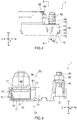
- Fig. 4 is a front view of the battery state detection device 1.
- Fig. 5 is an A-A cross-sectional view of the battery state detection device 1.
- the battery state detection device 1 includes a battery post terminal 10, a case 70, which accommodates a circuit board including a current sensing circuit that senses a current by being electrically connected to the battery post terminal 10, and a harness connection part 80 that is provided on the case 70 and to which a harness can be connected.
- the battery post terminal 10 includes a holding part 11 held on one of the faces (for example, a bottom portion 72) of the case 70, and an insert part 12 provided in a region from the holding part 11 along a face adjacent to one of the faces (for example, an upper face portion 71) of the case 70.
- the battery post terminal 10 contacts the case 70 via at least two faces including one of the faces and a face adjacent thereto of the case 70.
- the case 70 includes a fitting part 74 that fits around the insert part 12 by accommodating the insert part 12.
- the battery state detection device 1 will be specifically described.
- Figs. 6 and 7 are perspective views of the case 70 of the battery state detection device 1.
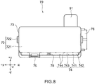
- Fig. 8 is a bottom view of the case 70 of the battery state detection device 1.
- the case 70 includes an upper face portion 71, a bottom portion 72, a side face portion 73, the fitting part 74, a locking part 75, a connector part 76, and a first rib 78.
- the case 70 has an internal space (i.e., a substrate accommodating part 77; see Fig. 5 ) surrounded by the upper face portion 71, the bottom portion 72, and the side face portion 73.
- the case 70 is open on the side of the bottom portion 72, and the substrate accommodating part 77 communicates with the outside through the opening.
- the case 70 is formed in the shape of a substantially rectangular parallelepiped box, for example.
- the case 70 is made of resin, for example.
- the substrate accommodating part 77 of the case 70 accommodates a circuit board 90 including a current sensing circuit that senses a current by being electrically connected to the battery post terminal 10.
- the circuit board 90 has a shunt resistor 91 having disposed therein a resistive element (for example, Manganin) with a known resistance value.
- the shunt resistor 91 is electrically connected to the circuit board 90, and is partially exposed to the outside of the case 70 through the side face portion 73 on the rear side in Fig. 1 of the case 70.
- the shunt resistor 91 is electrically connected to the battery post terminal 10 via a shunt resistor connection part 13 of the battery post terminal 10.
- the upper face portion 71 forms the upper face of the case 70 formed in the shape of a box.
- the upper face portion 71 has the connector part 76 formed thereon.
- the upper face portion 71 has the harness connection part 80 to which a harness (not illustrated) can be connected.
- the connector part 76 may be molded either integrally with or separately from the upper face portion 71.
- the bottom portion 72 is provided in the bottom face of the case 70 formed in the shape of a box, that is, provided facing the upper face portion 71 on the side below the upper face portion 71.
- the bottom portion 72 is formed in a rectangular or substantially rectangular shape as seen from below.
- the bottom portion 72 closes the opening (not illustrated) provided on the lower side of the case 70.
- the bottom portion 72 includes a bottom portion body 721 formed in a flat or substantially flat shape, for example, and a claw part 722 provided on the side face of the bottom portion body 721 on the short-side side.
- the claw part 722 is inserted into an insertion hole (not illustrated) provided in the side face portion 73 on the short-side side, thereby fixing the bottom portion 72 in the aforementioned opening of the case 70.
- the side face portion 73 forms the side face of the case 70 formed in the shape of a box.
- the side face portion 73 is provided continuously with the upper face portion 71 so as to surround the outer periphery of the upper face portion 71.
- the side face portion 73 has on its front side the fitting part 74 into which the insert part 12 of the battery post terminal 10 is insertable, for example.
- a terminal of the shunt resistor 91 is exposed to the outside through the side face portion 73 on the rear side.
- the side face portion 73 has on its short-side side an insertion hole (not illustrated) into which the aforementioned claw part 722 is adapted to be inserted, for example.
- the fitting part 74 is provided on the side face portion 73 of the case 70, specifically, on the side face portion 73 on the front side.
- the fitting part 74 includes an opening 741, an accommodating part 742, and the locking part 75.
- the opening 741 is open to the lower side of the case 70.
- the accommodating part 742 is adapted to have the insert part 12 of the battery post terminal 10 inserted therein as illustrated in Figs. 1 to 5 . Therefore, the accommodating part 742 is formed in the shape of a recessed groove with a predetermined depth so that the accommodating part 742 can accommodate the insert part 12.
- the locking part 75 is locked in a fixation hole 14 of the insert part 12 inserted in the accommodating part 742, thereby fixing the battery post terminal 10 and the case 70 together.
- the locking part 75 is provided at a position facing the fixation hole 14 of the insert part 12 in a state in which the insert part 12 is accommodated in the accommodating part 742.
- the locking part 75 is formed in the shape of a claw extending to the inner side of the case 70, that is, the inner side of the accommodating part 742 so as to be locked in the fixation hole 14 provided in the insert part 12.
- the first rib 78 extends from the substrate accommodating part 77 to the fitting part 74 on the inner side of the upper face portion 71.
- the first rib 78 is provided to reinforce the upper face portion 71 of the case 70.
- the harness connection part 80 is provided for connection of a harness (not illustrated) for electrical components.
- the shape and position of the harness connection part 80 are not particularly limited in the battery state detection device 1.
- Figs. 9 and 10 are perspective views of the battery post terminal 10 of the battery state detection device 1.
- the battery post terminal 10 has a sloped member 40 fastened thereto with a bolt 50 and a nut 60 as a fastening member in the up-down direction.
- the battery post terminal 10 is formed of a conductive metal material.
- the battery post terminal 10 includes the holding part 11 located on the front side in Fig. 9 , the insert part 12 located on the front side of the holding part 11, and the shunt resistor connection part 13 located on the rear side of the holding part 11.
- the battery post terminal 10 includes an electrode fitting part 21 located on the rear side of the shunt resistor connection part 13, and a fixation part 31 located on the rear side of the electrode fitting part 21.
- the holding part 11, the insert part 12, the shunt resistor connection part 13, the fixation hole 14, the electrode fitting part 21, and the fixation part 31 are integrally formed.
- the holding part 11 held on the bottom portion 72 of the case 70 of the battery state detection device 1 so as to cover the bottom portion 72 is formed in a shape corresponding to the shape of the bottom portion 72, for example, in a rectangular or substantially rectangular shape. More specifically, the holding part 11 has a shape corresponding to the shape of the bottom face of the case 70 so as to cover the bottom portion 72 and the outer periphery of the bottom face of the case 70. With such a shape, the holding part 11 holds the entire bottom face of the case 70.
- the holding part 11 can be formed in any shape in conformity with the shape of the bottom portion 72 of the case 70.
- the holding part 11 also serves as a structural member that supports the case 70.
- the insert part 12 is a standing wall-like member extending in the direction of the upper face portion 71 from an end portion on the front side of the holding part 11 along the side face portion 73 of the case 70 disposed above the holding part 11.
- the insert part 12 is integrally formed with the holding part 11, for example.
- the insert part 12 has a cutout part 15 at its end portion. The cutout part 15 is provided at a position facing the first rib 78 (see Fig. 8 ) provided in the accommodating part 742 of the fitting part 74 of the case 70.
- the shunt resistor connection part 13 is provided such that it extends upward from the position of the holding part 11.
- the shunt resistor connection part 13 has a flat face along the horizontal direction, and the face is electrically connected to the shunt resistor 91 that is exposed to the outside of the case 70 by extending outward through the side face portion 73 on the rear side in Fig. 1 of the case 70.
- the shunt resistor connection part 13 is provided at a position facing the side face portion 73 on the rear face side of the case 70, for example.
- the shunt resistor connection part 13 and the shunt resistor 91 are electrically connected, so that the battery and the harness (which are not illustrated) are electrically connected.
- the fixation hole 14 is a hole provided in the insert part 12.
- the fixation hole 14 is provided at a position facing the locking part 75 when the insert part 12 is inserted into the fitting part 74.
- the fixation hole 14 is adapted to have the locking part 75 locked therein and thus have the locking part 75 fixed therein.
- the case 70 is fixed to the battery post terminal 10.
- the electrode fitting part 21 fixes the battery post terminal 10 to the battery post (not illustrated).
- the electrode fitting part 21 is formed in a substantially frustum shape having an internal space in conformity with the shape of the battery post that is in a substantially frustum shape.
- the electrode fitting part 21 has formed in its center a circular fitting hole penetrating the space in the up-down direction.
- the inner peripheral surface of the electrode fitting part 21 is inclined so as to be in surface contact with the inclined outer peripheral surface of the battery post.
- the inner peripheral surface of the electrode fitting part 21 has a plurality of grooves with gaps therebetween in the circumferential direction, thereby increasing a fastening force for receiving the outer peripheral surface of the battery post.
- the electrode fitting part 21 is attached to the battery post such that the inner peripheral surface of the electrode fitting part 21 is covered from the upper side of the battery post.
- the electrode fitting part 21 is formed integrally and continuously with the holding part 11 at a portion on the rear side, the electrode fitting part 21 at a portion on the front side is branched (or split) to the right and left across its inner peripheral surface.
- the fixation part 31 is formed such that it extends to the front side from each of the distal end portions of the electrode fitting part 21 branched to the right and left.
- the fixation part 31 is formed such that it extends to the front side from the right and left sides of the electrode fitting part 21 and can accommodate a threaded portion of the bolt 50 therein.
- the fixation part 31 has the sloped member 40 attached thereto such that the fixation part 31 is covered with the sloped member 40 from above.
- the sloped member 40 has four leg portions extending downward from four corners of a substantially quadrangular upper face portion, and an insertion hole provided in the center of the upper face portion.
- the sides of the upper face portion are shorter in the front-rear direction than in the right-left direction.
- the insertion hole is adapted to have the threaded portion of the bolt 50 described below inserted therethrough.
- the right and left inner sides of each leg portion are sloped. Such slops are formed at the same inclination angle as the inclined plane of the fixation part 31, and thus, the inclined plane and the slopes are in surface contact with each other in a state in which the sloped member 40 is attached to the fixation part 31.
- the bolt 50 includes, as illustrated in Fig. 1 , the threaded portion extending in the up-down direction, and a head portion located on the lower side of the threaded portion.
- the threaded portion has formed thereon a screw thread in the range of a predetermined length from the distal end portion of the threaded portion facing upward.
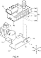
- Fig. 11 is an exploded perspective view of the battery state detection device 1.
- Fig. 12 is an exploded perspective view of the battery state detection device 1.
- the insert part 12 is accommodated in the accommodating part 742, so that the case 70 is fixed to the battery post terminal 10. At this time, the bottom portion 72 of the case 70 holds the holding part 11 of the battery post terminal 10.
- the insert part 12 is accommodated in the accommodating part 742 through the opening 741.
- the locking part 75 provided on the fitting part 74 is locked in the fixation hole 14 provided in the insert part 12.
- the position of the cutout part 15 provided at the distal end portion corresponds to the position of the first rib 78 provided on the inner side of the case 70. Therefore, the insert part 12 is reliably accommodated in the accommodating part 742.
- the battery state detection device 1 can, when an operator detaches the battery state detection device 1 from the battery by holding the case 70, receive a force of detaching the battery state detection device 1 with the holding part 11 made of metal.
- a load applied when the battery state detection device 1 is detached from the battery can be distributed to the portion of the bottom portion 72 held by the holding part 11, specifically, to the outer peripheral portion of the bottom portion 72 of the case 70.
- a load is less likely to be applied to the case 70 made of resin, and thus, the durability of the case 70 can be improved.
- the insert part 12 of the battery post terminal 10 is accommodated in the accommodating part 742 of the fitting part 74 of the case 70. Therefore, according to the battery state detection device 1, a load applied when the battery state detection device 1 is detached from the battery can also be distributed to portions other than the portion of the bottom portion 72 held by the holding part 11.
- the fixation hole 14 provided in the insert part 12 of the battery post terminal 10, and the locking part 75 provided in the case 70 are held. Therefore, according to the battery state detection device 1, even when a load is applied to the case 70 while the battery state detection device 1 is detached from the battery, the case 70 can be prevented from falling off the battery post terminal 10 and thus being damaged.
- the present invention is not limited thereto, and can be modified and changed in a variety of ways based on the technical idea of the present invention.
- the shape of the holding part 11 of the battery post terminal 10 is not limited to the aforementioned rectangular or substantially rectangular shape, and it is acceptable as long as the holding part 11 has a shape corresponding to the shape of the bottom portion 72 so that the holding part 11 is held at the outer peripheral portion of the bottom portion 72 of the case 70 and can distribute a force applied to the holding part 11 from the case 70.
- the holding part 11 need not be an entirely flat plate without irregularities, and may be partially provided with holes or irregularities, for example.
- the shape of the insert part 12 is not limited to the aforementioned shape as long as the insert part 12 can be inserted into the fitting part 74 of the case 70.
- the shape of the fitting part 74 of the case 70 is not limited to the aforementioned shape, and it is acceptable as long as the fitting part 74 has a shape corresponding to the shape of the insert part 12 so that the fitting part 74 can fit around the insert part 12.
- the positions and shapes of the fixation hole 14 and the cutout part 15 are not limited to the aforementioned shapes, either.
- an inner wall part 743 may have second ribs 744 at positions facing the insert part 12 in a state in which the insert part 12 is accommodated in the fitting part 74.
- the second ribs 744 are crush ribs, and the distance therebetween in the y-axis direction on the opposite sides of the inner wall part 743 is the same as or slightly smaller than the plate thickness of the insert part 12. Therefore, when the insert part 12 is accommodated in the accommodating part 742 of the fitting part 74, the second ribs 744 are scraped or squashed as the insert part 12 is press-fitted, so that the insert part 12 can be held more securely.
- the second ribs 744 are preferably triangular or semi-circular in shape, for example, as seen in a cross-sectional view, but the shapes of the second ribs 744 are not limited thereto.
- the battery post terminal 10 may include the electrode fitting part 21, the fixation part 31, the sloped member 40, the bolt 50, and the nut 60 with configurations different from those described above.
- case 70 may include the connector part 76 with a configuration different from that described above.
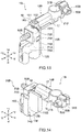
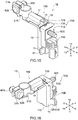
- Figs. 13 to 16 are perspective views of the battery state detection device 1B according to the second embodiment.
- Fig. 17 is a front view of the battery state detection device 1B.
- Fig. 18 is an A-A cross-sectional view of the battery state detection device 1B.
- the battery state detection device 1B includes a battery post terminal 10B, a case 70B, which accommodates a circuit board including a current sensing circuit that senses a current by being electrically connected to the battery post terminal 10B, and a harness connection part 80B that is provided on the case 70B and to which a harness can be connected.
- the battery post terminal 10B includes an electrode fitting part 21B that fixes the battery post terminal 10B to a battery post, an extension part 16 extending from the electrode fitting part 21B, a holding part 11B that is provided by bending the extension part 16 and is joined to a bottom portion 72B of the case 70B so as to cover the bottom portion 72B, reinforcing parts 112 and 162 that reinforce the extension part 16 and the holding part 11B, and an insert part 12B provided such that it extends from the holding part 11B along a side face portion 73B of the case 70B.
- the case 70B includes a fitting part 74B that fits around the insert part 12B by accommodating the insert part 12B.
- the battery state detection device 1B will be specifically described.
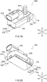
- Figs. 19 and 20 are perspective views of the case 70B of the battery state detection device 1B.
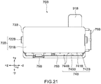
- Fig. 21 is a bottom view of the case 70B of the battery state detection device 1B.
- the case 70B includes an upper face portion 71B, the bottom portion 72B, the side face portion 73B, the fitting part 74B, a locking part 75B, a connector part 76B, and a first rib 78B.
- the case 70B has an internal space (i.e., a substrate accommodating part 77B; see Fig. 18 ) surrounded by the upper face portion 71B, the bottom portion 72B, and the side face portion 73B.
- the case 70B is open on the side of the bottom portion 72B, and the substrate accommodating part 77B communicates with the outside through the opening.
- the substrate accommodating part 77B is closed from the outside.
- the case 70B is formed in the shape of a substantially rectangular parallelepiped box, for example.
- the case 70B is made of resin, for example.
- the substrate accommodating part 77B of the case 70B accommodates a circuit board 90B including a current sensing circuit that senses a current by being electrically connected to the battery post terminal 10B.
- the circuit board 90B has a shunt resistor 91B having disposed therein a resistive element (for example, Manganin) with a known resistance value.
- the shunt resistor 91B is electrically connected to the circuit board 90B, and is partially exposed to the outside of the case 70B through the side face portion 73B on the rear side of the case 70B as illustrated in Figs. 15 and 16 .
- the shunt resistor 91B is electrically connected to the battery post terminal 10B via a shunt resistor connection part 13B of the battery post terminal 10B.
- the upper face portion 71B forms the upper face of the case 70B formed in the shape of a box.
- the upper face portion 71B has the connector part 76B formed thereon.
- the upper face portion 71B has the harness connection part 80B to which a harness (not illustrated) can be connected.
- the connector part 76B may be molded either integrally with or separately from the upper face portion 71B.
- the bottom portion 72B is provided in the bottom face of the case 70B formed in the shape of a box, that is, provided facing the upper face portion 71B on the side below the upper face portion 71B.
- the bottom portion 72B is formed in a rectangular or substantially rectangular shape as seen from below.
- the bottom portion 72B closes the opening (not illustrated) provided on the lower side of the case 70B.
- the bottom portion 72B includes a bottom portion body 721B formed in a flat or substantially flat shape, for example, and a claw part 722B provided on the side face of the bottom portion body 721B on the short-side side.
- the claw part 722B is inserted into an insertion hole (not illustrated) provided in the side face portion 73B on the short-side side, thereby fixing the bottom portion 72B in the aforementioned opening of the case 70B.
- the side face portion 73B forms the side face of the case 70B formed in the shape of a box.
- the side face portion 73B is provided continuously with the upper face portion 71B so as to surround the outer periphery of the upper face portion 71B.
- the side face portion 73B has on its front side the fitting part 74B into which the insert part 12B of the battery post terminal 10B is insertable, for example.
- a terminal of the shunt resistor 91B is exposed to the outside through the side face portion 73B on the rear side.
- the side face portion 73B has on its short-side side an insertion hole (not illustrated) into which the aforementioned claw part 722B is adapted to be inserted, for example.
- the fitting part 74B is provided on the side face portion 73B of the case 70B, specifically, on the side face portion 73B on the front side.
- the fitting part 74B includes an opening 741B, an accommodating part 742B, an inner wall part 743B, second ribs 744B, and the locking part 75B.
- the opening 741B is open to the lower side of the case 70B.
- the accommodating part 742B is adapted to have the insert part 12B of the battery post terminal 10B inserted therein as illustrated in Figs. 13 to 17 . Therefore, the accommodating part 742B is formed in the shape of a recessed groove with a predetermined depth so that the accommodating part 742B can accommodate the insert part 12B.
- the accommodating part 742B is provided with the inner wall part 743B to surround and accommodate the insert part 12B.
- the inner wall part 743B is provided with the plurality of second ribs 744B extending along the horizontal direction (i.e., the x-axis direction) with predetermined gaps therebetween, for accommodating the insert part 12B.
- the second ribs 744B are formed on the opposite sides of the inner wall part 743B in the accommodating part 742B.
- the second ribs 744B are provided to allow the plate-like insert part 12B, which has been inserted into the accommodating part 742B, to be press-fitted in the thickness direction (i.e., the y-axis direction). Therefore, in the accommodating part 742B, the distance between the opposite second ribs 744B in the y-axis direction is the same as or slightly smaller than the plate thickness of the insert part 12B.
- the second ribs 744B are not limited to the ones provided away from each other in the z-axis direction on the opposite sides of the inner wall part 743B as illustrated in Fig. 21 . That is, the second ribs 744B may be provided facing each other on the opposite sides of the inner wall part 743B.
- the locking part 75B is locked in a fixation hole 14B of the insert part 12B inserted in the accommodating part 742B, thereby fixing the battery post terminal 10B and the case 70B together.
- the locking part 75B is provided at a position facing the fixation hole 14B of the insert part 12B in a state in which the insert part 12B is accommodated in the accommodating part 742B.
- the locking part 75B is formed in the shape of a claw extending to the inner side of the case 70B, that is, the inner side of the accommodating part 742B so as to be locked in the fixation hole 14B provided in the insert part 12B.
- the first rib 78B extends from the substrate accommodating part 77B to the fitting part 74B on the inner side of the upper face portion 71B.
- the first rib 78B is provided to reinforce the upper face portion 71B of the case 70B.
- the harness connection part 80B is provided for connection of a harness (not illustrated) for electrical components.
- the shape and position of the harness connection part 80B are not particularly limited in the battery state detection device 1B.
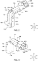
- Figs. 22 and 23 are perspective views of the battery post terminal 10B of the battery state detection device 1B.
- the battery post terminal 10B has a plate-like member 40B fastened thereto with a bolt 50B and a nut 60B as a fastening member in the front-rear direction.
- the battery post terminal 10B is formed of a conductive metal material.
- the battery post terminal 10B includes the electrode fitting part 21B provided on the right side in Fig.
- the extension part 16 extending to the left side from the electrode fitting part 21B, the holding part 11B that is formed by bending the extension part 16 at a bent part 163 and has its longitudinal direction lying along the up-down direction (i.e., the z-axis direction), the insert part 12B located on the front side of the holding part 11B, and the shunt resistor connection part 13B located on the rear side of the holding part 11B.
- the battery post terminal 10B includes a fixation part 31B located on the right side of the electrode fitting part 21B.
- the holding part 11B, the insert part 12B, the shunt resistor connection part 13B, the fixation hole 14B, the extension part 16, the electrode fitting part 21B, and the fixation part 31B are integrally formed.
- the extension part 16 and the holding part 11B of the battery post terminal 10B are formed along a planar portion of a housing of a battery (not illustrated) provided with the battery post.
- the extension part 16 is formed along a face, which is provided with the battery post, of the housing of the battery, for example, the upper face of the housing of the battery, together with the electrode fitting part 21B.
- the holding part 11B is formed along a face connected to the face, which is provided with the battery post, of the housing of the battery, via a bent portion, for example, the side face of the housing of the battery.
- the holding part 11B is provided by bending the extension part 16 at the bent part 163 in the downward direction (i.e., the z-axis direction).
- the holding part 11B is joined to the bottom portion 72B of the case 70B of the battery state detection device 1B so as to cover the bottom portion 72B.
- the holding part 11B is formed in a shape corresponding to the shape of the bottom portion 72B, for example, a rectangular or substantially rectangular shape. More specifically, the holding part 11B has a shape corresponding to the shape of the bottom face of the case 70B so as to cover the bottom portion 72B and the outer periphery of the bottom face of the case 70B. With such a shape, the holding part 11B is joined to the entire bottom face of the case 70B.
- the holding part 11B can be formed in any shape in conformity with the shape of the bottom portion 72B of the case 70B.
- the holding part 11B also serves as a structural member that supports the case 70B.
- the holding part 11B has the rib-like reinforcing part 112 formed thereon by bending a plate-like holding part body 111, which extends along the z-axis direction, along the longitudinal direction of the plate-like holding part body 111.
- the holding part 11B is provided with a standing wall part 19 extending from an end portion on the rear side.
- the insert part 12B is a standing wall-like member that is bent at and extends from an end portion on the front side of the holding part 11B toward the upper face portion 71B along the side face portion 73B of the case 70B disposed above the holding part 11B.
- the insert part 12B is formed integrally with the holding part 11B, for example.
- the insert part 12B has a cutout part 15B at its end portion.
- the cutout part 15B is provided at a position facing the first rib 78B (see Fig. 21 ) provided in the accommodating part 742B of the fitting part 74B of the case 70B.
- the shunt resistor connection part 13B is bent at and extends from an end portion of the standing wall part 19 to the rear side.
- the shunt resistor connection part 13B has a flat face along the horizontal direction and the up-down direction, and the face is electrically connected to the shunt resistor 91B that is exposed to the outside of the case 70B by extending outward through the side face portion 73B on the rear side in Figs. 15 and 16 of the case 70B.
- the shunt resistor connection part 13B is provided at a position facing the side face portion 73B on the rear face side of the case 70B, for example.
- the shunt resistor connection part 13B and the shunt resistor 91B are electrically connected, so that the battery and the harness (which are not illustrated) are electrically connected.
- the fixation hole 14B is a hole provided in the insert part 12B.
- the fixation hole 14B is provided at a position facing the locking part 75B when the insert part 12B is inserted into the fitting part 74B.
- the fixation hole 14B is adapted to have the locking part 75B locked therein and thus have the locking part 75B fixed therein.
- the case 70B is fixed to the battery post terminal 10B.
- the electrode fitting part 21B fixes the battery post terminal 10B to the battery post (not illustrated).
- the electrode fitting part 21B is formed in a substantially frustum shape having an internal space in conformity with the shape of the battery post that is in a substantially frustum shape.
- the electrode fitting part 21B has formed in its center a circular fitting hole penetrating the space in the up-down direction.
- the inner peripheral surface of the electrode fitting part 21B is inclined so as to be in surface contact with the inclined outer peripheral surface of the battery post.
- the inner peripheral surface of the electrode fitting part 21B has a plurality of grooves with gaps therebetween in the circumferential direction, thereby increasing a fastening force for receiving the outer peripheral surface of the battery post.
- the electrode fitting part 21B is attached to the battery post such that the inner peripheral surface of the electrode fitting part 21B is covered from the upper side of the battery post.
- the electrode fitting part 21B is formed integrally and continuously with the extension part 16 at a portion on the left side, the electrode fitting part 21B at a portion on the right side is branched (or split) to the front and rear across its inner peripheral surface.
- the fixation part 31B is formed such that it extends to the right side from each of the distal end portions of the electrode fitting part 21B branched to the front and rear.
- the fixation part 31B is formed such that it extends to the right side from the electrode fitting part 21B and can accommodate a threaded portion of the bolt 50B therein.
- the fixation part 31B has the plate-like member 40B attached thereto.
- the plate-like member 40B is formed in a substantially quadrangular shape, and has an insertion hole at its center.
- the insertion hole is adapted to have the threaded portion of the bolt 50B described below inserted therethrough.
- the plate-like member 40B is in surface contact with the fixation part 31B in a state in which the plate-like member 40B is attached to the fixation part 31B.
- the bolt 50B includes, as illustrated in Fig. 13 , the threaded portion extending in the front-rear direction, and a head portion located on the rear side of the threaded portion.
- the threaded portion has formed thereon a screw thread in the range of a predetermined length from the distal end portion of the threaded portion facing the front side.
- the extension part 16 is provided such that it extends to the left side in the horizontal direction (i.e., the x-axis direction) from the electrode fitting part 21B.
- the extension part 16 includes a planar part 161, the reinforcing part 162, and the bent part 163.
- the planar part 161 is a substantially flat plate-like member lying along the horizontal direction and formed integrally with the electrode fitting part 21B.
- the reinforcing part 162 is formed by bending the planar part 161 into a rib shape along the longitudinal direction (i.e., the x-axis direction).
- the bent part 163 is formed by bending an end portion on the left side of the planar part 161, which is opposite to an end portion on the right side in contact with the electrode fitting part 21B, in the downward direction (i.e., the -z-axis direction).
- the upper face of the planar part 161 of the extension part 16 is provided with a reinforcing member 17 formed by bending a plate-like member made of metal.
- the extension part 16 is provided with a standing wall part 18 extending from the insert part 12B.
- the extension part 16 is provided with a standing wall part 19 extending from the holding part 11B.
- Fig. 24 is an exploded perspective view of the battery state detection device 1B.
- Fig. 25 is an exploded perspective view of the battery state detection device 1B.
- the insert part 12B is accommodated in the accommodating part 742B, so that the case 70B is fixed to the battery post terminal 10B.
- the bottom portion 72B of the case 70B is joined to the holding part 11B of the battery post terminal 10B.
- the insert part 12B is accommodated in the accommodating part 742B through the opening 741B.
- the locking part 75B provided on the fitting part 74B is locked in the fixation hole 14B provided in the insert part 12B.
- the position of the cutout part 15B provided at a distal end portion corresponds to the position of the first rib 78B provided on the inner side of the case 70B. Therefore, the insert part 12B is reliably accommodated in the accommodating part 742B.
- the holding part 11B provided in the battery post terminal 10B made of metal is joined to the bottom portion 72B, which is the lower face portion, of the case 70B such that the holding part 11B covers the bottom portion 72B.
- the battery state detection device 1B can, when an operator detaches the battery state detection device 1B from the battery by holding the case 70B, receive a force of detaching the battery state detection device 1B with the holding part 11B made of metal.
- a load applied when the battery state detection device 1B is detached from the battery can be distributed to the joined portion of the holding part 11B and the bottom portion 72B, specifically, to the outer peripheral portion of the bottom portion 72B of the case 70B.
- a load is less likely to be applied to the case 70B made of resin, and thus, the durability of the case 70B can be improved.
- the insert part 12B of the battery post terminal 10B is accommodated in the accommodating part 742B of the fitting part 74B of the case 70B. Therefore, according to the battery state detection device 1B, a load applied when the battery state detection device 1B is detached from the battery can also be distributed to portions other than the joined portion of the holding part 11B and the bottom portion 72B.
- the fixation hole 14B provided in the insert part 12B of the battery post terminal 10B, and the locking part 75B provided in the case 70B are held. Therefore, according to the battery state detection device 1B, even when a load is applied to the case 70B while the battery state detection device 1B is detached from the battery, the case 70B can be prevented from falling off the battery post terminal 10B and thus being damaged.
- the present invention is not limited thereto, and can be modified and changed in a variety of ways based on the technical idea of the present invention.
- the shape of the holding part 11B of the battery post terminal 10B is not limited to the aforementioned rectangular or substantially rectangular shape, and it is acceptable as long as the holding part 11B has a shape corresponding to the shape of the bottom portion 72B so that the holding part 11B is joined to the outer peripheral portion of the bottom portion 72B of the case 70B and can distribute a force applied to the holding part 11B from the case 70B.
- the holding part 11B need not be an entirely flat plate without irregularities, and may be partially provided with holes or irregularities, for example.
- the shape of the insert part 12B is not limited to the aforementioned shape as long as the insert part 12B can be inserted into the fitting part 74B of the case 70B.
- the shape of the fitting part 74B of the case 70B is not limited to the aforementioned shape, and it is acceptable as long as the fitting part 74B has a shape corresponding to the shape of the insert part 12B so that the fitting part 74B can fit around the insert part 12B.
- the positions and shapes of the fixation hole 14B and the cutout part 15B are not limited to the aforementioned shapes, either.
- the inner wall part 743B may have the second ribs 744B at positions facing the insert part 12B in a state in which the insert part 12B is accommodated in the fitting part 74B.
- the second ribs 744B are crush ribs, and the distance therebetween in the y-axis direction on the opposite sides of the inner wall part 743B is the same as or slightly smaller than the plate thickness of the insert part 12B. Therefore, when the insert part 12B is accommodated in the accommodating part 742B of the fitting part 74B, the second ribs 744B as the crush ribs are scraped or squashed as the insert part 12B is press-fitted, so that the insert part 12B can be held more securely.
- the second ribs 744B are preferably triangular or semi-circular in shape, for example, as seen in a cross-sectional view, but the shapes of the second ribs 744B are not limited thereto.
- the battery post terminal 10B may include the electrode fitting part 21B, the fixation part 31B, the plate-like member 40B, the bolt 50B, and the nut 60B with configurations different from those described above.
- case 70B may include the connector part 76B with a configuration different from that described above.
Landscapes
- Physics & Mathematics (AREA)
- General Physics & Mathematics (AREA)
- Chemical & Material Sciences (AREA)
- Chemical Kinetics & Catalysis (AREA)
- Electrochemistry (AREA)
- General Chemical & Material Sciences (AREA)
- Engineering & Computer Science (AREA)
- Manufacturing & Machinery (AREA)
- Connection Of Batteries Or Terminals (AREA)
Abstract
Description
- The present invention relates to a battery state detection device.
- A battery state detection device is known that detects the state of a battery mounted on a vehicle, such as an automobile. The battery state detection device includes components, such as a shunt resistor and a circuit board, for sensing a current. Among battery state detection devices, those having a case for accommodating a circuit board, for example, are known (for example, see Patent Literature 1).
- Typically, a battery mounted on a vehicle has a battery post projecting from the upper face of the battery, and the battery post has a battery post terminal fixed thereto. The battery post terminal has power supply harnesses connected thereto. A battery state detection device is connected between the battery post terminal and the harnesses. In such a case, the battery state detection device is fixed to the battery post terminal.
- Patent Literature 1: International Publication No.
2014/203465 - By the way, regarding the conventional battery state detection device, there is a case where an operator holds the case of the battery state detection device when detaching the battery post terminal for replacing a battery.
- However, in the conventional battery state detection device, in such a case, a load may be applied to a portion of the case in contact with the battery post terminal.
- The present invention has been made in view of the foregoing problem, and it is an object of the present invention to provide a battery state detection device in which the durability of a case can be improved.
- A battery state detection device according to a representative embodiment of the present invention is a battery state detection device including a battery post terminal, a case accommodating a circuit board including a current sensing circuit that senses a current by being electrically connected to the battery post terminal, and a harness connection part provided on the case, the harness connection part being capable of having a harness connected thereto, in which the battery post terminal includes a holding part held on one of faces of the case, and an insert part provided in a region from the holding part along a face adjacent to the one of the faces of the case, the battery post terminal contacts the case via at least two faces, the two faces including the one of the faces and the face adjacent to the one of the faces, and the case includes a fitting part, the fitting part being adapted to fit around the insert part by accommodating the insert part.
- According to a battery state detection device according to the present invention, the durability of a case can be improved.
-
-
Fig. 1 A perspective view of a battery state detection device according to a first embodiment. -
Fig. 2 A perspective view of the battery state detection device according to the first embodiment. -
Fig. 3 A perspective view of the battery state detection device according to the first embodiment. -
Fig. 4 A front view of the battery state detection device according to the first embodiment. -
Fig. 5 An A-A cross-sectional view of the battery state detection device according to the first embodiment. -
Fig. 6 A perspective view of a case of the battery state detection device according to the first embodiment. -
Fig. 7 A perspective view of the case of the battery state detection device according to the first embodiment. -
Fig. 8 A bottom view of the case of the battery state detection device according to the first embodiment. -
Fig. 9 A perspective view of a battery post terminal of the battery state detection device according to the first embodiment. -
Fig. 10 A perspective view of the battery post terminal of the battery state detection device according to the first embodiment. -
Fig. 11 An exploded perspective view of the battery state detection device according to the first embodiment. -
Fig. 12 An exploded perspective view of the battery state detection device according to the first embodiment. -
Fig. 13 A perspective view of a battery state detection device according to a second embodiment. -
Fig. 14 A perspective view of the battery state detection device according to the second embodiment. -
Fig. 15 A perspective view of the battery state detection device according to the second embodiment. -
Fig. 16 A perspective view of the battery state detection device according to the second embodiment. -
Fig. 17 A front view of the battery state detection device according to the second embodiment. -
Fig. 18 An A-A cross-sectional view of the battery state detection device according to the second embodiment. -
Fig. 19 A perspective view of a case of the battery state detection device according to the second embodiment. -
Fig. 20 A perspective view of the case of the battery state detection device according to the second embodiment. -
Fig. 21 A bottom view of the case of the battery state detection device according to the second embodiment. -
Fig. 22 A perspective view of a battery post terminal of the battery state detection device according to the second embodiment. -
Fig. 23 A perspective view of the battery post terminal of the battery state detection device according to the second embodiment. -
Fig. 24 An exploded perspective view of the battery state detection device according to the second embodiment. -
Fig. 25 An exploded perspective view of the battery state detection device according to the second embodiment. - Hereinafter, battery
state detection devices - Hereinafter, a direction parallel with a direction along the side face of each of a
battery post terminal 10 of the batterystate detection device 1 inFig. 1 and abattery post terminal 10B of the batterystate detection device 1B inFig. 12 , that is, the direction of the axis of each of battery posts (not illustrated) held by thebattery post terminals state detection devices state detection devices state detection devices state detection devices state detection devices -
Figs. 1 to 3 are perspective views of a batterystate detection device 1 according to a first embodiment.Fig. 4 is a front view of the batterystate detection device 1.Fig. 5 is an A-A cross-sectional view of the batterystate detection device 1. - As illustrated in
Figs. 1 to 5 , the batterystate detection device 1 includes abattery post terminal 10, acase 70, which accommodates a circuit board including a current sensing circuit that senses a current by being electrically connected to thebattery post terminal 10, and aharness connection part 80 that is provided on thecase 70 and to which a harness can be connected. Thebattery post terminal 10 includes aholding part 11 held on one of the faces (for example, a bottom portion 72) of thecase 70, and aninsert part 12 provided in a region from theholding part 11 along a face adjacent to one of the faces (for example, an upper face portion 71) of thecase 70. Thebattery post terminal 10 contacts thecase 70 via at least two faces including one of the faces and a face adjacent thereto of thecase 70. Thecase 70 includes afitting part 74 that fits around theinsert part 12 by accommodating theinsert part 12. Hereinafter, the batterystate detection device 1 will be specifically described. - A specific configuration of the
case 70 will be described. -
Figs. 6 and 7 are perspective views of thecase 70 of the batterystate detection device 1.Fig. 8 is a bottom view of thecase 70 of the batterystate detection device 1. Thecase 70 includes anupper face portion 71, abottom portion 72, aside face portion 73, thefitting part 74, a lockingpart 75, aconnector part 76, and afirst rib 78. Thecase 70 has an internal space (i.e., asubstrate accommodating part 77; seeFig. 5 ) surrounded by theupper face portion 71, thebottom portion 72, and theside face portion 73. Thecase 70 is open on the side of thebottom portion 72, and thesubstrate accommodating part 77 communicates with the outside through the opening. When thebottom portion 72 is fixed to the portion of the opening of thecase 70 on the side of thebottom portion 72, thesubstrate accommodating part 77 is closed from the outside. Thecase 70 is formed in the shape of a substantially rectangular parallelepiped box, for example. Thecase 70 is made of resin, for example. - As illustrated in
Fig. 5 , thesubstrate accommodating part 77 of thecase 70 accommodates acircuit board 90 including a current sensing circuit that senses a current by being electrically connected to thebattery post terminal 10. Thecircuit board 90 has ashunt resistor 91 having disposed therein a resistive element (for example, Manganin) with a known resistance value. Theshunt resistor 91 is electrically connected to thecircuit board 90, and is partially exposed to the outside of thecase 70 through theside face portion 73 on the rear side inFig. 1 of thecase 70. Theshunt resistor 91 is electrically connected to thebattery post terminal 10 via a shuntresistor connection part 13 of thebattery post terminal 10. - As illustrated in
Figs. 6 to 8 , theupper face portion 71 forms the upper face of thecase 70 formed in the shape of a box. Theupper face portion 71 has theconnector part 76 formed thereon. In addition, theupper face portion 71 has theharness connection part 80 to which a harness (not illustrated) can be connected. It should be noted that theconnector part 76 may be molded either integrally with or separately from theupper face portion 71. - The
bottom portion 72 is provided in the bottom face of thecase 70 formed in the shape of a box, that is, provided facing theupper face portion 71 on the side below theupper face portion 71. Thebottom portion 72 is formed in a rectangular or substantially rectangular shape as seen from below. Thebottom portion 72 closes the opening (not illustrated) provided on the lower side of thecase 70. Thebottom portion 72 includes abottom portion body 721 formed in a flat or substantially flat shape, for example, and aclaw part 722 provided on the side face of thebottom portion body 721 on the short-side side. Theclaw part 722 is inserted into an insertion hole (not illustrated) provided in theside face portion 73 on the short-side side, thereby fixing thebottom portion 72 in the aforementioned opening of thecase 70. - The
side face portion 73 forms the side face of thecase 70 formed in the shape of a box. Theside face portion 73 is provided continuously with theupper face portion 71 so as to surround the outer periphery of theupper face portion 71. Theside face portion 73 has on its front side thefitting part 74 into which theinsert part 12 of thebattery post terminal 10 is insertable, for example. A terminal of theshunt resistor 91 is exposed to the outside through theside face portion 73 on the rear side. In addition, theside face portion 73 has on its short-side side an insertion hole (not illustrated) into which theaforementioned claw part 722 is adapted to be inserted, for example. - The
fitting part 74 is provided on theside face portion 73 of thecase 70, specifically, on theside face portion 73 on the front side. Thefitting part 74 includes anopening 741, anaccommodating part 742, and the lockingpart 75. - The
opening 741 is open to the lower side of thecase 70. Theaccommodating part 742 is adapted to have theinsert part 12 of thebattery post terminal 10 inserted therein as illustrated inFigs. 1 to 5 . Therefore, theaccommodating part 742 is formed in the shape of a recessed groove with a predetermined depth so that theaccommodating part 742 can accommodate theinsert part 12. - The locking
part 75 is locked in afixation hole 14 of theinsert part 12 inserted in theaccommodating part 742, thereby fixing thebattery post terminal 10 and thecase 70 together. The lockingpart 75 is provided at a position facing thefixation hole 14 of theinsert part 12 in a state in which theinsert part 12 is accommodated in theaccommodating part 742. Specifically, the lockingpart 75 is formed in the shape of a claw extending to the inner side of thecase 70, that is, the inner side of theaccommodating part 742 so as to be locked in thefixation hole 14 provided in theinsert part 12. - The
first rib 78 extends from thesubstrate accommodating part 77 to thefitting part 74 on the inner side of theupper face portion 71. Thefirst rib 78 is provided to reinforce theupper face portion 71 of thecase 70. - The
harness connection part 80 is provided for connection of a harness (not illustrated) for electrical components. The shape and position of theharness connection part 80 are not particularly limited in the batterystate detection device 1. - Next, a specific configuration of the
battery post terminal 10 will be described. -
Figs. 9 and 10 are perspective views of thebattery post terminal 10 of the batterystate detection device 1. Thebattery post terminal 10 has a slopedmember 40 fastened thereto with abolt 50 and anut 60 as a fastening member in the up-down direction. Thebattery post terminal 10 is formed of a conductive metal material. Thebattery post terminal 10 includes the holdingpart 11 located on the front side inFig. 9 , theinsert part 12 located on the front side of the holdingpart 11, and the shuntresistor connection part 13 located on the rear side of the holdingpart 11. In addition, thebattery post terminal 10 includes an electrodefitting part 21 located on the rear side of the shuntresistor connection part 13, and afixation part 31 located on the rear side of theelectrode fitting part 21. In thebattery post terminal 10, the holdingpart 11, theinsert part 12, the shuntresistor connection part 13, thefixation hole 14, theelectrode fitting part 21, and thefixation part 31 are integrally formed. - The holding
part 11 held on thebottom portion 72 of thecase 70 of the batterystate detection device 1 so as to cover thebottom portion 72 is formed in a shape corresponding to the shape of thebottom portion 72, for example, in a rectangular or substantially rectangular shape. More specifically, the holdingpart 11 has a shape corresponding to the shape of the bottom face of thecase 70 so as to cover thebottom portion 72 and the outer periphery of the bottom face of thecase 70. With such a shape, the holdingpart 11 holds the entire bottom face of thecase 70. The holdingpart 11 can be formed in any shape in conformity with the shape of thebottom portion 72 of thecase 70. The holdingpart 11 also serves as a structural member that supports thecase 70. - The
insert part 12 is a standing wall-like member extending in the direction of theupper face portion 71 from an end portion on the front side of the holdingpart 11 along theside face portion 73 of thecase 70 disposed above the holdingpart 11. Theinsert part 12 is integrally formed with the holdingpart 11, for example. Theinsert part 12 has acutout part 15 at its end portion. Thecutout part 15 is provided at a position facing the first rib 78 (seeFig. 8 ) provided in theaccommodating part 742 of thefitting part 74 of thecase 70. - The shunt
resistor connection part 13 is provided such that it extends upward from the position of the holdingpart 11. The shuntresistor connection part 13 has a flat face along the horizontal direction, and the face is electrically connected to theshunt resistor 91 that is exposed to the outside of thecase 70 by extending outward through theside face portion 73 on the rear side inFig. 1 of thecase 70. The shuntresistor connection part 13 is provided at a position facing theside face portion 73 on the rear face side of thecase 70, for example. In the batterystate detection device 1, the shuntresistor connection part 13 and theshunt resistor 91 are electrically connected, so that the battery and the harness (which are not illustrated) are electrically connected. - The
fixation hole 14 is a hole provided in theinsert part 12. Thefixation hole 14 is provided at a position facing the lockingpart 75 when theinsert part 12 is inserted into thefitting part 74. Thefixation hole 14 is adapted to have the lockingpart 75 locked therein and thus have the lockingpart 75 fixed therein. In the batterystate detection device 1, as thefixation hole 14 of thebattery post terminal 10 and the lockingpart 75 of thecase 70 engage each other, thecase 70 is fixed to thebattery post terminal 10. - The electrode
fitting part 21 fixes thebattery post terminal 10 to the battery post (not illustrated). The electrodefitting part 21 is formed in a substantially frustum shape having an internal space in conformity with the shape of the battery post that is in a substantially frustum shape. The electrodefitting part 21 has formed in its center a circular fitting hole penetrating the space in the up-down direction. The inner peripheral surface of theelectrode fitting part 21 is inclined so as to be in surface contact with the inclined outer peripheral surface of the battery post. In addition, the inner peripheral surface of theelectrode fitting part 21 has a plurality of grooves with gaps therebetween in the circumferential direction, thereby increasing a fastening force for receiving the outer peripheral surface of the battery post. The electrodefitting part 21 is attached to the battery post such that the inner peripheral surface of theelectrode fitting part 21 is covered from the upper side of the battery post. - Although the
electrode fitting part 21 is formed integrally and continuously with the holdingpart 11 at a portion on the rear side, theelectrode fitting part 21 at a portion on the front side is branched (or split) to the right and left across its inner peripheral surface. Thefixation part 31 is formed such that it extends to the front side from each of the distal end portions of theelectrode fitting part 21 branched to the right and left. - The
fixation part 31 is formed such that it extends to the front side from the right and left sides of theelectrode fitting part 21 and can accommodate a threaded portion of thebolt 50 therein. Thefixation part 31 has the slopedmember 40 attached thereto such that thefixation part 31 is covered with the slopedmember 40 from above. - The sloped
member 40 has four leg portions extending downward from four corners of a substantially quadrangular upper face portion, and an insertion hole provided in the center of the upper face portion. The sides of the upper face portion are shorter in the front-rear direction than in the right-left direction. The insertion hole is adapted to have the threaded portion of thebolt 50 described below inserted therethrough. The right and left inner sides of each leg portion are sloped. Such slops are formed at the same inclination angle as the inclined plane of thefixation part 31, and thus, the inclined plane and the slopes are in surface contact with each other in a state in which the slopedmember 40 is attached to thefixation part 31. - The
bolt 50 includes, as illustrated inFig. 1 , the threaded portion extending in the up-down direction, and a head portion located on the lower side of the threaded portion. The threaded portion has formed thereon a screw thread in the range of a predetermined length from the distal end portion of the threaded portion facing upward. - Next, the function of the battery
state detection device 1 in the first embodiment will be described. -
Fig. 11 is an exploded perspective view of the batterystate detection device 1.Fig. 12 is an exploded perspective view of the batterystate detection device 1. - As illustrated in
Figs. 11 and12 , in the batterystate detection device 1, when thecase 70 is attached to thebattery post terminal 10, theinsert part 12 is accommodated in theaccommodating part 742, so that thecase 70 is fixed to thebattery post terminal 10. At this time, thebottom portion 72 of thecase 70 holds the holdingpart 11 of thebattery post terminal 10. - More specifically, the
insert part 12 is accommodated in theaccommodating part 742 through theopening 741. When theinsert part 12 is accommodated in theaccommodating part 742, the lockingpart 75 provided on thefitting part 74 is locked in thefixation hole 14 provided in theinsert part 12. In theaccommodating part 742, the position of thecutout part 15 provided at the distal end portion corresponds to the position of thefirst rib 78 provided on the inner side of thecase 70. Therefore, theinsert part 12 is reliably accommodated in theaccommodating part 742. - With the aforementioned structure, in the battery
state detection device 1, thebottom portion 72, which is the lower face portion, of thecase 70 is held such that it is covered with the holdingpart 11 provided in thebattery post terminal 10 made of metal. According to such a configuration, the batterystate detection device 1 can, when an operator detaches the batterystate detection device 1 from the battery by holding thecase 70, receive a force of detaching the batterystate detection device 1 with the holdingpart 11 made of metal. Specifically, according to the aforementioned batterystate detection device 1, a load applied when the batterystate detection device 1 is detached from the battery can be distributed to the portion of thebottom portion 72 held by the holdingpart 11, specifically, to the outer peripheral portion of thebottom portion 72 of thecase 70. Thus, according to the aforementioned batterystate detection device 1, a load is less likely to be applied to thecase 70 made of resin, and thus, the durability of thecase 70 can be improved. - In addition, in the battery
state detection device 1, theinsert part 12 of thebattery post terminal 10 is accommodated in theaccommodating part 742 of thefitting part 74 of thecase 70. Therefore, according to the batterystate detection device 1, a load applied when the batterystate detection device 1 is detached from the battery can also be distributed to portions other than the portion of thebottom portion 72 held by the holdingpart 11. - Further, in the battery
state detection device 1, thefixation hole 14 provided in theinsert part 12 of thebattery post terminal 10, and the lockingpart 75 provided in thecase 70 are held. Therefore, according to the batterystate detection device 1, even when a load is applied to thecase 70 while the batterystate detection device 1 is detached from the battery, thecase 70 can be prevented from falling off thebattery post terminal 10 and thus being damaged. - Although the battery
state detection device 1 according to the first embodiment of the present invention has been described above, the present invention is not limited thereto, and can be modified and changed in a variety of ways based on the technical idea of the present invention. - The shape of the holding
part 11 of thebattery post terminal 10 is not limited to the aforementioned rectangular or substantially rectangular shape, and it is acceptable as long as the holdingpart 11 has a shape corresponding to the shape of thebottom portion 72 so that the holdingpart 11 is held at the outer peripheral portion of thebottom portion 72 of thecase 70 and can distribute a force applied to the holdingpart 11 from thecase 70. In addition, the holdingpart 11 need not be an entirely flat plate without irregularities, and may be partially provided with holes or irregularities, for example. The shape of theinsert part 12 is not limited to the aforementioned shape as long as theinsert part 12 can be inserted into thefitting part 74 of thecase 70. - The shape of the
fitting part 74 of thecase 70 is not limited to the aforementioned shape, and it is acceptable as long as thefitting part 74 has a shape corresponding to the shape of theinsert part 12 so that thefitting part 74 can fit around theinsert part 12. In addition, the positions and shapes of thefixation hole 14 and thecutout part 15 are not limited to the aforementioned shapes, either. - In the
fitting part 74 of thecase 70, aninner wall part 743 may havesecond ribs 744 at positions facing theinsert part 12 in a state in which theinsert part 12 is accommodated in thefitting part 74. Thesecond ribs 744 are crush ribs, and the distance therebetween in the y-axis direction on the opposite sides of theinner wall part 743 is the same as or slightly smaller than the plate thickness of theinsert part 12. Therefore, when theinsert part 12 is accommodated in theaccommodating part 742 of thefitting part 74, thesecond ribs 744 are scraped or squashed as theinsert part 12 is press-fitted, so that theinsert part 12 can be held more securely. Thesecond ribs 744 are preferably triangular or semi-circular in shape, for example, as seen in a cross-sectional view, but the shapes of thesecond ribs 744 are not limited thereto. - The
battery post terminal 10 may include theelectrode fitting part 21, thefixation part 31, the slopedmember 40, thebolt 50, and thenut 60 with configurations different from those described above. - In addition, the
case 70 may include theconnector part 76 with a configuration different from that described above. - Hereinafter, a battery
state detection device 1B according to a second embodiment of the present invention will be described with reference to the drawings. -
Figs. 13 to 16 are perspective views of the batterystate detection device 1B according to the second embodiment.Fig. 17 is a front view of the batterystate detection device 1B.Fig. 18 is an A-A cross-sectional view of the batterystate detection device 1B. - As illustrated in
Figs. 13 to 18 , the batterystate detection device 1B includes abattery post terminal 10B, acase 70B, which accommodates a circuit board including a current sensing circuit that senses a current by being electrically connected to thebattery post terminal 10B, and aharness connection part 80B that is provided on thecase 70B and to which a harness can be connected. Thebattery post terminal 10B includes an electrodefitting part 21B that fixes thebattery post terminal 10B to a battery post, anextension part 16 extending from the electrodefitting part 21B, a holdingpart 11B that is provided by bending theextension part 16 and is joined to abottom portion 72B of thecase 70B so as to cover thebottom portion 72B, reinforcingparts extension part 16 and the holdingpart 11B, and aninsert part 12B provided such that it extends from the holdingpart 11B along aside face portion 73B of thecase 70B. Thecase 70B includes afitting part 74B that fits around theinsert part 12B by accommodating theinsert part 12B. Hereinafter, the batterystate detection device 1B will be specifically described. - A specific configuration of the
case 70B will be described. -
Figs. 19 and 20 are perspective views of thecase 70B of the batterystate detection device 1B.Fig. 21 is a bottom view of thecase 70B of the batterystate detection device 1B. Thecase 70B includes anupper face portion 71B, thebottom portion 72B, theside face portion 73B, thefitting part 74B, a lockingpart 75B, aconnector part 76B, and afirst rib 78B. Thecase 70B has an internal space (i.e., a substrate accommodating part 77B; seeFig. 18 ) surrounded by theupper face portion 71B, thebottom portion 72B, and theside face portion 73B. Thecase 70B is open on the side of thebottom portion 72B, and the substrate accommodating part 77B communicates with the outside through the opening. When thebottom portion 72B is fixed to the portion of the opening of thecase 70B on the side of thebottom portion 72B, the substrate accommodating part 77B is closed from the outside. Thecase 70B is formed in the shape of a substantially rectangular parallelepiped box, for example. Thecase 70B is made of resin, for example. - As illustrated in
Fig. 17 , the substrate accommodating part 77B of thecase 70B accommodates acircuit board 90B including a current sensing circuit that senses a current by being electrically connected to thebattery post terminal 10B. Thecircuit board 90B has ashunt resistor 91B having disposed therein a resistive element (for example, Manganin) with a known resistance value. Theshunt resistor 91B is electrically connected to thecircuit board 90B, and is partially exposed to the outside of thecase 70B through theside face portion 73B on the rear side of thecase 70B as illustrated inFigs. 15 and 16 . Theshunt resistor 91B is electrically connected to thebattery post terminal 10B via a shuntresistor connection part 13B of thebattery post terminal 10B. - As illustrated in
Figs. 19 to 21 , theupper face portion 71B forms the upper face of thecase 70B formed in the shape of a box. Theupper face portion 71B has theconnector part 76B formed thereon. In addition, theupper face portion 71B has theharness connection part 80B to which a harness (not illustrated) can be connected. It should be noted that theconnector part 76B may be molded either integrally with or separately from theupper face portion 71B. - The
bottom portion 72B is provided in the bottom face of thecase 70B formed in the shape of a box, that is, provided facing theupper face portion 71B on the side below theupper face portion 71B. Thebottom portion 72B is formed in a rectangular or substantially rectangular shape as seen from below. Thebottom portion 72B closes the opening (not illustrated) provided on the lower side of thecase 70B. Thebottom portion 72B includes abottom portion body 721B formed in a flat or substantially flat shape, for example, and aclaw part 722B provided on the side face of thebottom portion body 721B on the short-side side. Theclaw part 722B is inserted into an insertion hole (not illustrated) provided in theside face portion 73B on the short-side side, thereby fixing thebottom portion 72B in the aforementioned opening of thecase 70B. - The
side face portion 73B forms the side face of thecase 70B formed in the shape of a box. Theside face portion 73B is provided continuously with theupper face portion 71B so as to surround the outer periphery of theupper face portion 71B. Theside face portion 73B has on its front side thefitting part 74B into which theinsert part 12B of thebattery post terminal 10B is insertable, for example. A terminal of theshunt resistor 91B is exposed to the outside through theside face portion 73B on the rear side. In addition, theside face portion 73B has on its short-side side an insertion hole (not illustrated) into which theaforementioned claw part 722B is adapted to be inserted, for example. - The
fitting part 74B is provided on theside face portion 73B of thecase 70B, specifically, on theside face portion 73B on the front side. Thefitting part 74B includes anopening 741B, anaccommodating part 742B, aninner wall part 743B,second ribs 744B, and the lockingpart 75B. - The
opening 741B is open to the lower side of thecase 70B. Theaccommodating part 742B is adapted to have theinsert part 12B of thebattery post terminal 10B inserted therein as illustrated inFigs. 13 to 17 . Therefore, theaccommodating part 742B is formed in the shape of a recessed groove with a predetermined depth so that theaccommodating part 742B can accommodate theinsert part 12B. Theaccommodating part 742B is provided with theinner wall part 743B to surround and accommodate theinsert part 12B. Theinner wall part 743B is provided with the plurality ofsecond ribs 744B extending along the horizontal direction (i.e., the x-axis direction) with predetermined gaps therebetween, for accommodating theinsert part 12B. Thesecond ribs 744B are formed on the opposite sides of theinner wall part 743B in theaccommodating part 742B. Thesecond ribs 744B are provided to allow the plate-like insert part 12B, which has been inserted into theaccommodating part 742B, to be press-fitted in the thickness direction (i.e., the y-axis direction). Therefore, in theaccommodating part 742B, the distance between the oppositesecond ribs 744B in the y-axis direction is the same as or slightly smaller than the plate thickness of theinsert part 12B. - It should be noted that the
second ribs 744B are not limited to the ones provided away from each other in the z-axis direction on the opposite sides of theinner wall part 743B as illustrated inFig. 21 . That is, thesecond ribs 744B may be provided facing each other on the opposite sides of theinner wall part 743B. - The locking
part 75B is locked in afixation hole 14B of theinsert part 12B inserted in theaccommodating part 742B, thereby fixing thebattery post terminal 10B and thecase 70B together. The lockingpart 75B is provided at a position facing thefixation hole 14B of theinsert part 12B in a state in which theinsert part 12B is accommodated in theaccommodating part 742B. Specifically, the lockingpart 75B is formed in the shape of a claw extending to the inner side of thecase 70B, that is, the inner side of theaccommodating part 742B so as to be locked in thefixation hole 14B provided in theinsert part 12B. - The
first rib 78B extends from the substrate accommodating part 77B to thefitting part 74B on the inner side of theupper face portion 71B. Thefirst rib 78B is provided to reinforce theupper face portion 71B of thecase 70B. - The
harness connection part 80B is provided for connection of a harness (not illustrated) for electrical components. The shape and position of theharness connection part 80B are not particularly limited in the batterystate detection device 1B. - Next, a specific configuration of the
battery post terminal 10B will be described. -
Figs. 22 and 23 are perspective views of thebattery post terminal 10B of the batterystate detection device 1B. Thebattery post terminal 10B has a plate-like member 40B fastened thereto with abolt 50B and anut 60B as a fastening member in the front-rear direction. Thebattery post terminal 10B is formed of a conductive metal material. Thebattery post terminal 10B includes the electrodefitting part 21B provided on the right side inFig. 22 , theextension part 16 extending to the left side from the electrodefitting part 21B, the holdingpart 11B that is formed by bending theextension part 16 at abent part 163 and has its longitudinal direction lying along the up-down direction (i.e., the z-axis direction), theinsert part 12B located on the front side of the holdingpart 11B, and the shuntresistor connection part 13B located on the rear side of the holdingpart 11B. In addition, thebattery post terminal 10B includes afixation part 31B located on the right side of the electrodefitting part 21B. In thebattery post terminal 10B, the holdingpart 11B, theinsert part 12B, the shuntresistor connection part 13B, thefixation hole 14B, theextension part 16, the electrodefitting part 21B, and thefixation part 31B are integrally formed. - Herein, the
extension part 16 and the holdingpart 11B of thebattery post terminal 10B are formed along a planar portion of a housing of a battery (not illustrated) provided with the battery post. Specifically, theextension part 16 is formed along a face, which is provided with the battery post, of the housing of the battery, for example, the upper face of the housing of the battery, together with the electrodefitting part 21B. In addition, the holdingpart 11B is formed along a face connected to the face, which is provided with the battery post, of the housing of the battery, via a bent portion, for example, the side face of the housing of the battery. - The holding
part 11B is provided by bending theextension part 16 at thebent part 163 in the downward direction (i.e., the z-axis direction). The holdingpart 11B is joined to thebottom portion 72B of thecase 70B of the batterystate detection device 1B so as to cover thebottom portion 72B. The holdingpart 11B is formed in a shape corresponding to the shape of thebottom portion 72B, for example, a rectangular or substantially rectangular shape. More specifically, the holdingpart 11B has a shape corresponding to the shape of the bottom face of thecase 70B so as to cover thebottom portion 72B and the outer periphery of the bottom face of thecase 70B. With such a shape, the holdingpart 11B is joined to the entire bottom face of thecase 70B. The holdingpart 11B can be formed in any shape in conformity with the shape of thebottom portion 72B of thecase 70B. The holdingpart 11B also serves as a structural member that supports thecase 70B. The holdingpart 11B has the rib-like reinforcingpart 112 formed thereon by bending a plate-likeholding part body 111, which extends along the z-axis direction, along the longitudinal direction of the plate-likeholding part body 111. The holdingpart 11B is provided with a standingwall part 19 extending from an end portion on the rear side. - The
insert part 12B is a standing wall-like member that is bent at and extends from an end portion on the front side of the holdingpart 11B toward theupper face portion 71B along theside face portion 73B of thecase 70B disposed above the holdingpart 11B. Theinsert part 12B is formed integrally with the holdingpart 11B, for example. Theinsert part 12B has acutout part 15B at its end portion. Thecutout part 15B is provided at a position facing thefirst rib 78B (seeFig. 21 ) provided in theaccommodating part 742B of thefitting part 74B of thecase 70B. - The shunt
resistor connection part 13B is bent at and extends from an end portion of the standingwall part 19 to the rear side. The shuntresistor connection part 13B has a flat face along the horizontal direction and the up-down direction, and the face is electrically connected to theshunt resistor 91B that is exposed to the outside of thecase 70B by extending outward through theside face portion 73B on the rear side inFigs. 15 and 16 of thecase 70B. The shuntresistor connection part 13B is provided at a position facing theside face portion 73B on the rear face side of thecase 70B, for example. In the batterystate detection device 1B, the shuntresistor connection part 13B and theshunt resistor 91B are electrically connected, so that the battery and the harness (which are not illustrated) are electrically connected. - The
fixation hole 14B is a hole provided in theinsert part 12B. Thefixation hole 14B is provided at a position facing the lockingpart 75B when theinsert part 12B is inserted into thefitting part 74B. Thefixation hole 14B is adapted to have the lockingpart 75B locked therein and thus have the lockingpart 75B fixed therein. In the batterystate detection device 1B, as thefixation hole 14B of thebattery post terminal 10B and the lockingpart 75B of thecase 70B are held, thecase 70B is fixed to thebattery post terminal 10B. - The electrode
fitting part 21B fixes thebattery post terminal 10B to the battery post (not illustrated). The electrodefitting part 21B is formed in a substantially frustum shape having an internal space in conformity with the shape of the battery post that is in a substantially frustum shape. The electrodefitting part 21B has formed in its center a circular fitting hole penetrating the space in the up-down direction. The inner peripheral surface of the electrodefitting part 21B is inclined so as to be in surface contact with the inclined outer peripheral surface of the battery post. In addition, the inner peripheral surface of the electrodefitting part 21B has a plurality of grooves with gaps therebetween in the circumferential direction, thereby increasing a fastening force for receiving the outer peripheral surface of the battery post. The electrodefitting part 21B is attached to the battery post such that the inner peripheral surface of the electrodefitting part 21B is covered from the upper side of the battery post. - Although the electrode
fitting part 21B is formed integrally and continuously with theextension part 16 at a portion on the left side, the electrodefitting part 21B at a portion on the right side is branched (or split) to the front and rear across its inner peripheral surface. Thefixation part 31B is formed such that it extends to the right side from each of the distal end portions of the electrodefitting part 21B branched to the front and rear. - The
fixation part 31B is formed such that it extends to the right side from the electrodefitting part 21B and can accommodate a threaded portion of thebolt 50B therein. Thefixation part 31B has the plate-like member 40B attached thereto. - The plate-
like member 40B is formed in a substantially quadrangular shape, and has an insertion hole at its center. The insertion hole is adapted to have the threaded portion of thebolt 50B described below inserted therethrough. The plate-like member 40B is in surface contact with thefixation part 31B in a state in which the plate-like member 40B is attached to thefixation part 31B. - The
bolt 50B includes, as illustrated inFig. 13 , the threaded portion extending in the front-rear direction, and a head portion located on the rear side of the threaded portion. The threaded portion has formed thereon a screw thread in the range of a predetermined length from the distal end portion of the threaded portion facing the front side. - The
extension part 16 is provided such that it extends to the left side in the horizontal direction (i.e., the x-axis direction) from the electrodefitting part 21B. Theextension part 16 includes aplanar part 161, the reinforcingpart 162, and thebent part 163. Theplanar part 161 is a substantially flat plate-like member lying along the horizontal direction and formed integrally with the electrodefitting part 21B. The reinforcingpart 162 is formed by bending theplanar part 161 into a rib shape along the longitudinal direction (i.e., the x-axis direction). Thebent part 163 is formed by bending an end portion on the left side of theplanar part 161, which is opposite to an end portion on the right side in contact with the electrodefitting part 21B, in the downward direction (i.e., the -z-axis direction). - The upper face of the
planar part 161 of theextension part 16 is provided with a reinforcingmember 17 formed by bending a plate-like member made of metal. In addition, theextension part 16 is provided with a standingwall part 18 extending from theinsert part 12B. Further, theextension part 16 is provided with a standingwall part 19 extending from the holdingpart 11B. - Next, the function of the battery
state detection device 1B in the second embodiment will be described. -
Fig. 24 is an exploded perspective view of the batterystate detection device 1B.Fig. 25 is an exploded perspective view of the batterystate detection device 1B. - As illustrated in
Figs. 24 and25 , in the batterystate detection device 1B, when thecase 70B is attached to thebattery post terminal 10B, theinsert part 12B is accommodated in theaccommodating part 742B, so that thecase 70B is fixed to thebattery post terminal 10B. At this time, thebottom portion 72B of thecase 70B is joined to the holdingpart 11B of thebattery post terminal 10B. - More specifically, the
insert part 12B is accommodated in theaccommodating part 742B through theopening 741B. When theinsert part 12B is accommodated in theaccommodating part 742B, the lockingpart 75B provided on thefitting part 74B is locked in thefixation hole 14B provided in theinsert part 12B. In theaccommodating part 742B, the position of thecutout part 15B provided at a distal end portion corresponds to the position of thefirst rib 78B provided on the inner side of thecase 70B. Therefore, theinsert part 12B is reliably accommodated in theaccommodating part 742B. - With the aforementioned structure, in the battery
state detection device 1B, the holdingpart 11B provided in thebattery post terminal 10B made of metal is joined to thebottom portion 72B, which is the lower face portion, of thecase 70B such that the holdingpart 11B covers thebottom portion 72B. According to such a configuration, the batterystate detection device 1B can, when an operator detaches the batterystate detection device 1B from the battery by holding thecase 70B, receive a force of detaching the batterystate detection device 1B with the holdingpart 11B made of metal. Specifically, according to the aforementioned batterystate detection device 1B, a load applied when the batterystate detection device 1B is detached from the battery can be distributed to the joined portion of the holdingpart 11B and thebottom portion 72B, specifically, to the outer peripheral portion of thebottom portion 72B of thecase 70B. Thus, according to the aforementioned batterystate detection device 1B, a load is less likely to be applied to thecase 70B made of resin, and thus, the durability of thecase 70B can be improved. - In addition, in the battery
state detection device 1B, theinsert part 12B of thebattery post terminal 10B is accommodated in theaccommodating part 742B of thefitting part 74B of thecase 70B. Therefore, according to the batterystate detection device 1B, a load applied when the batterystate detection device 1B is detached from the battery can also be distributed to portions other than the joined portion of the holdingpart 11B and thebottom portion 72B. - Further, in the battery
state detection device 1B, thefixation hole 14B provided in theinsert part 12B of thebattery post terminal 10B, and the lockingpart 75B provided in thecase 70B are held. Therefore, according to the batterystate detection device 1B, even when a load is applied to thecase 70B while the batterystate detection device 1B is detached from the battery, thecase 70B can be prevented from falling off thebattery post terminal 10B and thus being damaged. - Although the battery
state detection device 1B according to the second embodiment of the present invention has been described above, the present invention is not limited thereto, and can be modified and changed in a variety of ways based on the technical idea of the present invention. - The shape of the holding
part 11B of thebattery post terminal 10B is not limited to the aforementioned rectangular or substantially rectangular shape, and it is acceptable as long as the holdingpart 11B has a shape corresponding to the shape of thebottom portion 72B so that the holdingpart 11B is joined to the outer peripheral portion of thebottom portion 72B of thecase 70B and can distribute a force applied to the holdingpart 11B from thecase 70B. In addition, the holdingpart 11B need not be an entirely flat plate without irregularities, and may be partially provided with holes or irregularities, for example. The shape of theinsert part 12B is not limited to the aforementioned shape as long as theinsert part 12B can be inserted into thefitting part 74B of thecase 70B. - The shape of the
fitting part 74B of thecase 70B is not limited to the aforementioned shape, and it is acceptable as long as thefitting part 74B has a shape corresponding to the shape of theinsert part 12B so that thefitting part 74B can fit around theinsert part 12B. In addition, the positions and shapes of thefixation hole 14B and thecutout part 15B are not limited to the aforementioned shapes, either. - In the
fitting part 74B of thecase 70B, theinner wall part 743B may have thesecond ribs 744B at positions facing theinsert part 12B in a state in which theinsert part 12B is accommodated in thefitting part 74B. Thesecond ribs 744B are crush ribs, and the distance therebetween in the y-axis direction on the opposite sides of theinner wall part 743B is the same as or slightly smaller than the plate thickness of theinsert part 12B. Therefore, when theinsert part 12B is accommodated in theaccommodating part 742B of thefitting part 74B, thesecond ribs 744B as the crush ribs are scraped or squashed as theinsert part 12B is press-fitted, so that theinsert part 12B can be held more securely. Thesecond ribs 744B are preferably triangular or semi-circular in shape, for example, as seen in a cross-sectional view, but the shapes of thesecond ribs 744B are not limited thereto. - The
battery post terminal 10B may include the electrodefitting part 21B, thefixation part 31B, the plate-like member 40B, thebolt 50B, and thenut 60B with configurations different from those described above. - In addition, the
case 70B may include theconnector part 76B with a configuration different from that described above. -
- 1, 1B battery state detection device
- 10, 10B battery post terminal
- 11, 11B holding part
- 12, 12B insert part
- 13, 13B shunt resistor connection part
- 14, 14B fixation hole
- 15, 15B cutout part
- 16 extension part
- 17 reinforcing member
- 18 standing wall part
- 19 standing wall part
- 21, 21B electrode fitting part
- 31, 31B fixation part
- 40 sloped member
- 40B plate-like member
- 50, 50B bolt
- 60, 60B nut
- 70, 70B case
- 71, 71B upper face portion
- 72, 72B bottom portion
- 73, 73B side face portion
- 74, 74B fitting part
- 75, 75B locking part
- 76, 76B connector part
- 77, 77B substrate accommodating part
- 78, 78B first rib
- 80, 80B harness connection part
- 90, 90B circuit board
- 91, 91B shunt resistor
- 111 holding part body
- 112 reinforcing part
- 161 planar part
- 162 reinforcing part
- 163 bent part
- 721, 721B bottom portion body
- 722, 722B claw part
- 741, 741B opening
- 742, 742B accommodating part
- 743, 743B inner wall part
- 744, 744B second rib
Claims (14)
- A battery state detection device comprising:a battery post terminal;a case accommodating a circuit board, the circuit board including a current sensing circuit that senses a current by being electrically connected to the battery post terminal; anda harness connection part provided on the case, the harness connection part being capable of having a harness connected thereto,wherein:the battery post terminal includesa holding part held on one of faces of the case, andan insert part provided in a region from the holding part along a face adjacent to the one of the faces of the case,the battery post terminal contacts the case via at least two faces, the two faces including the one of the faces and the face adjacent to the one of the faces, andthe case includes a fitting part, the fitting part being adapted to fit around the insert part by accommodating the insert part.
- The battery state detection device according to claim 1, wherein the fitting part includes a locking part, the locking part being adapted to fix the insert part that has been inserted.
- The battery state detection device according to claim 2,
wherein:the locking part is formed in a shape of a claw extending to an inner side of the case, andthe insert part has a fixation hole provided at a position facing the locking part in a state in which the insert part is accommodated in the fitting part, the fixation hole being adapted to have the locking part locked and fixed therein. - The battery state detection device according to any one of claims 1 to 3,
wherein:a shunt resistor electrically connected to the circuit board is partially exposed to an outside of the case, andthe battery post terminal includes a shunt resistor connection part electrically connected to a part of the shunt resistor exposed from the case. - The battery state detection device according to any one of claims 1 to 4,
wherein:the case includes a first rib on an inner side of an upper face of the case, the first rib extending to the fitting part, andthe insert part has a cutout part at an end portion of the insert part, the cutout part being located at a position facing the first rib. - The battery state detection device according to any one of claims 1 to 5,
wherein:the case includes a second rib on the fitting part, andthe second rib is provided at a position facing the insert part in a state in which the insert part is accommodated in the fitting part. - The battery state detection device according to claim 1,
wherein:the battery post terminal includesan electrode fitting part adapted to fix the battery post terminal to a battery post,an extension part extending from the electrode fitting part, anda reinforcing part adapted to reinforce the extension part and the holding part, andthe holding part is provided by bending the extension part. - The battery state detection device according to claim 7, wherein the reinforcing part is formed through bending along a longitudinal direction of the extension part and the holding part.
- The battery state detection device according to claim 7 or 8, wherein the extension part is provided with a reinforcing member.
- The battery state detection device according to any one of claims 7 to 9, wherein the fitting part includes a locking part, the locking part being adapted to fix the insert part that has been inserted.
- The battery state detection device according to claim 10,
wherein:the locking part is formed in a shape of a claw extending to an inner side of the case, andthe insert part has a fixation hole provided at a position facing the locking part in a state in which the insert part is accommodated in the fitting part, the fixation hole being adapted to have the locking part locked and fixed therein. - The battery state detection device according to any one of claims 7 to 11,
wherein:the case includes a shunt resistor electrically connected to the circuit board,the shunt resistor is partially exposed to an outside of the case through a side face of the case on a side opposite to the fitting part, andthe battery post terminal includes a shunt resistor connection part provided on a side opposite to the insert part of the holding part, the shunt resistor connection part being electrically connected to a part of the shunt resistor exposed from the case. - The battery state detection device according to any one of claims 7 to 12, wherein the extension part and the holding part are formed along a housing of a battery provided with the battery post.
- The battery state detection device according to any one of claims 7 to 13,
wherein:the case includes a second rib on the fitting part, andthe second rib is provided at a position facing the insert part in a state in which the insert part is accommodated in the fitting part.
Applications Claiming Priority (3)
| Application Number | Priority Date | Filing Date | Title |
|---|---|---|---|
| JP2019073920A JP7112983B2 (en) | 2019-04-09 | 2019-04-09 | Battery status detection device |
| JP2019075240A JP7112984B2 (en) | 2019-04-11 | 2019-04-11 | Battery status detection device |
| PCT/JP2020/015604 WO2020209237A1 (en) | 2019-04-09 | 2020-04-07 | Battery state detection device |
Publications (2)
| Publication Number | Publication Date |
|---|---|
| EP3930077A1 true EP3930077A1 (en) | 2021-12-29 |
| EP3930077A4 EP3930077A4 (en) | 2024-10-02 |
Family
ID=72751274
Family Applications (1)
| Application Number | Title | Priority Date | Filing Date |
|---|---|---|---|
| EP20786907.4A Pending EP3930077A4 (en) | 2019-04-09 | 2020-04-07 | BATTERY STATE DETECTION DEVICE |
Country Status (4)
| Country | Link |
|---|---|
| US (1) | US11971453B2 (en) |
| EP (1) | EP3930077A4 (en) |
| CN (1) | CN113632292B (en) |
| WO (1) | WO2020209237A1 (en) |
Family Cites Families (13)
| Publication number | Priority date | Publication date | Assignee | Title |
|---|---|---|---|---|
| JP3451186B2 (en) * | 1998-02-17 | 2003-09-29 | 株式会社オートネットワーク技術研究所 | Circuit breaker |
| US6222439B1 (en) | 1998-02-17 | 2001-04-24 | Sumitomo Wiring Systems, Ltd. | Circuit breaking device |
| JP4151327B2 (en) * | 2002-07-09 | 2008-09-17 | 住友電装株式会社 | Battery fuse unit |
| DE10330568B4 (en) | 2002-07-09 | 2008-01-24 | Sumitomo Wiring Systems, Ltd., Yokkaichi | fuse box |
| JP2011164008A (en) * | 2010-02-12 | 2011-08-25 | Denso Corp | Current detector |
| JP2011181297A (en) * | 2010-03-01 | 2011-09-15 | Yazaki Corp | Battery terminal with current sensor |
| JP6127522B2 (en) * | 2013-01-09 | 2017-05-17 | スズキ株式会社 | Variable valve operating device for internal combustion engine |
| JP5755263B2 (en) * | 2013-01-25 | 2015-07-29 | 古河電気工業株式会社 | Battery status detection device |
| JP6089105B2 (en) * | 2013-06-11 | 2017-03-01 | 古河電気工業株式会社 | Battery sensor positioning tool, battery sensor assembly including the same, and battery sensor |
| JP6479472B2 (en) | 2013-06-20 | 2019-03-06 | 古河電気工業株式会社 | Battery state detection device and manufacturing method thereof |
| CN105264388B (en) * | 2013-06-20 | 2019-09-03 | 古河电气工业株式会社 | Battery status detection device |
| EP3300143B1 (en) * | 2015-07-01 | 2020-04-01 | The Furukawa Electric Co., Ltd. | Battery state sensing device and manufacturing method therefor |
| JP6757500B2 (en) * | 2017-04-10 | 2020-09-23 | トヨタ自動車株式会社 | Non-aqueous electrolyte secondary battery |
-
2020
- 2020-04-07 WO PCT/JP2020/015604 patent/WO2020209237A1/en not_active Ceased
- 2020-04-07 CN CN202080022231.6A patent/CN113632292B/en active Active
- 2020-04-07 EP EP20786907.4A patent/EP3930077A4/en active Pending
-
2021
- 2021-09-24 US US17/448,749 patent/US11971453B2/en active Active
Also Published As
| Publication number | Publication date |
|---|---|
| US20220011367A1 (en) | 2022-01-13 |
| CN113632292B (en) | 2024-07-16 |
| CN113632292A (en) | 2021-11-09 |
| US11971453B2 (en) | 2024-04-30 |
| EP3930077A4 (en) | 2024-10-02 |
| WO2020209237A1 (en) | 2020-10-15 |
Similar Documents
| Publication | Publication Date | Title |
|---|---|---|
| US9748066B2 (en) | Fuse unit attachment structure | |
| JP5668655B2 (en) | Conductive plate and joint connector | |
| US10581053B2 (en) | Connection module for a power storage group of plural power storage elements | |
| JP6686806B2 (en) | Terminal module | |
| US10218038B2 (en) | Battery sensor positioner, battery sensor assembly equipped with same, and battery sensor | |
| US10574043B2 (en) | Electrical connection box | |
| US20150140392A1 (en) | Bus bar module | |
| JP7067368B2 (en) | Electrical junction box | |
| EP3675298B1 (en) | Electrical connection box | |
| EP2159882B1 (en) | A battery terminal unit and method of mounting it | |
| US11971453B2 (en) | Battery state detection device | |
| JP2014017167A (en) | Fixing structure of fuse holder and fuse cover | |
| JP5755263B2 (en) | Battery status detection device | |
| CN110473753B (en) | Storage battery terminal with fuse holder | |
| JP7112984B2 (en) | Battery status detection device | |
| JP7112983B2 (en) | Battery status detection device | |
| CN111293650B (en) | Electric connection box | |
| US20230378682A1 (en) | Terminal unit | |
| JP2023048180A (en) | Resin component for battery terminal, and battery terminal unit | |
| JP5012297B2 (en) | Connector device | |
| US12470051B2 (en) | Junction box assembly with recessed key features | |
| JP7534160B2 (en) | Terminal cover | |
| JP2023170359A (en) | shield connector | |
| CN121769540A (en) | Terminal block | |
| US10874017B2 (en) | Board unit |
Legal Events
| Date | Code | Title | Description |
|---|---|---|---|
| STAA | Information on the status of an ep patent application or granted ep patent |
Free format text: STATUS: THE INTERNATIONAL PUBLICATION HAS BEEN MADE |
|
| PUAI | Public reference made under article 153(3) epc to a published international application that has entered the european phase |
Free format text: ORIGINAL CODE: 0009012 |
|
| STAA | Information on the status of an ep patent application or granted ep patent |
Free format text: STATUS: REQUEST FOR EXAMINATION WAS MADE |
|
| 17P | Request for examination filed |
Effective date: 20210923 |
|
| AK | Designated contracting states |
Kind code of ref document: A1 Designated state(s): AL AT BE BG CH CY CZ DE DK EE ES FI FR GB GR HR HU IE IS IT LI LT LU LV MC MK MT NL NO PL PT RO RS SE SI SK SM TR |
|
| DAV | Request for validation of the european patent (deleted) | ||
| DAX | Request for extension of the european patent (deleted) | ||
| A4 | Supplementary search report drawn up and despatched |
Effective date: 20240830 |
|
| RIC1 | Information provided on ipc code assigned before grant |
Ipc: H01R 11/28 20060101ALI20240826BHEP Ipc: H01M 50/569 20210101ALI20240826BHEP Ipc: G01R 31/36 20200101ALI20240826BHEP Ipc: G01R 31/364 20190101ALI20240826BHEP Ipc: G01R 1/04 20060101ALI20240826BHEP Ipc: H01M 10/48 20060101AFI20240826BHEP |